EP3272694A1 - Jib connection structure - Google Patents
Jib connection structure Download PDFInfo
- Publication number
- EP3272694A1 EP3272694A1 EP15886204.5A EP15886204A EP3272694A1 EP 3272694 A1 EP3272694 A1 EP 3272694A1 EP 15886204 A EP15886204 A EP 15886204A EP 3272694 A1 EP3272694 A1 EP 3272694A1
- Authority
- EP
- European Patent Office
- Prior art keywords
- jib
- base end
- boom
- insertion holes
- connection shaft
- Prior art date
- Legal status (The legal status is an assumption and is not a legal conclusion. Google has not performed a legal analysis and makes no representation as to the accuracy of the status listed.)
- Granted
Links
Images




Classifications
-
- B—PERFORMING OPERATIONS; TRANSPORTING
- B66—HOISTING; LIFTING; HAULING
- B66C—CRANES; LOAD-ENGAGING ELEMENTS OR DEVICES FOR CRANES, CAPSTANS, WINCHES, OR TACKLES
- B66C23/00—Cranes comprising essentially a beam, boom, or triangular structure acting as a cantilever and mounted for translatory of swinging movements in vertical or horizontal planes or a combination of such movements, e.g. jib-cranes, derricks, tower cranes
- B66C23/62—Constructional features or details
- B66C23/64—Jibs
- B66C23/70—Jibs constructed of sections adapted to be assembled to form jibs or various lengths
-
- B—PERFORMING OPERATIONS; TRANSPORTING
- B66—HOISTING; LIFTING; HAULING
- B66C—CRANES; LOAD-ENGAGING ELEMENTS OR DEVICES FOR CRANES, CAPSTANS, WINCHES, OR TACKLES
- B66C23/00—Cranes comprising essentially a beam, boom, or triangular structure acting as a cantilever and mounted for translatory of swinging movements in vertical or horizontal planes or a combination of such movements, e.g. jib-cranes, derricks, tower cranes
- B66C23/62—Constructional features or details
- B66C23/64—Jibs
- B66C23/70—Jibs constructed of sections adapted to be assembled to form jibs or various lengths
- B66C23/701—Jibs constructed of sections adapted to be assembled to form jibs or various lengths telescopic
- B66C23/702—Jibs constructed of sections adapted to be assembled to form jibs or various lengths telescopic with a jib extension boom
-
- B—PERFORMING OPERATIONS; TRANSPORTING
- B66—HOISTING; LIFTING; HAULING
- B66C—CRANES; LOAD-ENGAGING ELEMENTS OR DEVICES FOR CRANES, CAPSTANS, WINCHES, OR TACKLES
- B66C23/00—Cranes comprising essentially a beam, boom, or triangular structure acting as a cantilever and mounted for translatory of swinging movements in vertical or horizontal planes or a combination of such movements, e.g. jib-cranes, derricks, tower cranes
- B66C23/62—Constructional features or details
- B66C23/64—Jibs
- B66C23/66—Outer or upper end constructions
-
- B—PERFORMING OPERATIONS; TRANSPORTING
- B66—HOISTING; LIFTING; HAULING
- B66C—CRANES; LOAD-ENGAGING ELEMENTS OR DEVICES FOR CRANES, CAPSTANS, WINCHES, OR TACKLES
- B66C23/00—Cranes comprising essentially a beam, boom, or triangular structure acting as a cantilever and mounted for translatory of swinging movements in vertical or horizontal planes or a combination of such movements, e.g. jib-cranes, derricks, tower cranes
- B66C23/88—Safety gear
Definitions
- the present invention relates to jib connection structures, and more specifically, to a connection structure between a boom leading end and jib base end.
- Patent Literature 1 discloses a jib connection structure composed of a jib connection shaft projecting in both lateral directions of a boom leading end and jib base end engagement portions provided at a bifurcated jib base end.
- the jib base end engagement portions are U-shaped and can be engaged with the jib connection shaft.
- the jib base end engagement portions can be connected to the jib connection shaft by engaging the jib base end engagement portions with the jib connection shaft and inserting pins into through holes in leading ends of the jib base end engagement portions.
- a jib is firstly placed in a lower holding position of a boom and the jib base end engagement portions are connected to the jib connection shaft. At this time, the jib is placed at a slight angle with respect to the boom ("offset placement").
- One of the jib base end engagement portions is formed to be longer than the other to allow the pins to be inserted into the through holes in the jib base end engagement portions while the jib base end engagement portions remain in the offset placement.
- the boom is elevated up, so that the jib is suspended from the boom leading end.
- the jib is projected, by exerting tension on a tension rod.
- a jib stowage operation is done in a procedure reverse to the jib projection operation.
- the jib base end engagement portions on the right and left have longitudinal dimensions different from each other, and the pins on the right and left to be inserted into the jib base end engagement portions are also located at different positions. Accordingly, in a state where the jib is suspended from the boom leading end, only one of the pins is locked to the jib connection shaft, and the jib is suspended at this one point. Consequently, there is a problem that the jib swings sideways and is not stabilized, so that it is difficult to carry out the jib projection/stowage operation.
- a jib connection structure of a first aspect of the invention is a connection structure between a leading end of a boom and a base end of a jib, the connection structure including a jib connection shaft horizontally projecting in both lateral directions of the leading end of the boom; and jib base end engagement portions provided at respective ends of the bifurcated base end of the jib, in which: the jib base end engagement portions are U-shaped into which the jib connection shaft is allowed to be fitted, and include insertion holes for insertion of pins, the pins being intended for preventing slipping off of the jib connection shaft; the insertion holes in one of the jib base end engagement portions are placed laterally outwardly from a U-shaped bottom portion; and the insertion holes are located at a position at which the pins are allowed to be inserted into the insertion holes in a state where the jib connection shaft is fitted into the jib base end engagement portions and a leading end of the j
- a jib connection structure of a second aspect of the present invention is a connection structure between a leading end of a boom and a base end of a jib, the connection structure including a jib connection shaft horizontally projecting in both lateral directions of the leading end of the boom; and jib base end engagement portions provided at respective ends of the bifurcated base end of the jib, in which: the jib base end engagement portions are U-shaped into which the jib connection shaft is allowed to be fitted, and include insertion holes for insertion of pins, the pins being intended for preventing slipping off of the jib connection shaft; the insertion holes in one of the jib base end engagement portions are placed laterally outwardly from a U-shaped bottom portion; a line that connects the right and left insertion holes is inclined with respect to a plane perpendicular to a central axis of the jib; and a center of gravity of the jib lies between two planes perpendic
- the jib in the state where the jib is suspended from the boom leading end, the right and left pins are locked to the jib connection shaft, and the jib is suspended at two points. Therefore, the jib is restrained from swinging sideways, and a jib projection/stowage operation is easily carried out.
- a jib connection structure according to one embodiment of the invention is applied, for example, to mobile crane C as illustrated in FIG. 1 .
- the jib connection structure according to the embodiment is not limited to mobile crane C as illustrated in FIG. 1 and can be applied to different cranes.
- Reference numeral 11 in FIG. 1 indicates a traveling chassis provided with wheels for traveling.
- Slewing base 12 is mounted on chassis 11 in such a manner as to be able to slew 360 degrees in the horizontal plane by a slewing motor.
- Slewing base 12 is provided with operator's cab 13.
- Boom 14 is attached to slewing base 12 such that boom 14 can be freely elevated and lowered.
- a base end of boom 14 is pivotally supported by a pin on slewing base 12.
- a boom elevating cylinder is attached between boom 14 and slewing base 12.
- Boom 14 is elevated when the boom elevating cylinder is extended, and lowered when the boom elevating cylinder is retracted.
- Boom 14 is a telescopically designed multi-section boom and is extended or retracted by a telescopic cylinder.
- a wire rope provided with a hook (not illustrated) is suspended from leading end 14a of boom 14, and is guided along boom 14 to slewing base 12 and wound around a winch.
- the winch is driven to rotate forward and reverse by a hoist motor, to wind up and pay out the wire rope, thereby allowing the hook to be moved up and down.
- Combination of slewing of slewing base 12; elevating, lowering, extending, and retracting of boom 14; and moving up and down of the hook allows loading and unloading in a three-dimensional space.
- mobile crane C is provided with jib 15.
- Jib 15 as a whole is an elongated bar member, base end 15a of which is bifurcated.
- Jib 15 is employed for achieving a lifting height and/or operating radius still greater than a lifting height and/or operating radius of the boom length of fully extended boom 14.
- jib 15 is stowed along a side of boom 14 (see FIG. 1 ).
- base end 15a of jib 15 is connected to leading end 14a of boom 14, and jib 15 is projected forward from boom 14 (see FIG. 10 ).
- the jib connection structure of the embodiment is a structure for connecting leading end 14a of boom 14 (hereinafter referred to as "boom leading end 14a”) to base end 15a of jib 15 (hereinafter referred to as “jib base end 15a”) in mobile crane C as described above.
- FIGS. 2 and 3 are side and bottom views illustrating a state where jib 15 is placed in a lower holding position in which jib 15 is placed along the bottom of boom 14.
- boom leading end 14a is connected to/disconnected from jib base end 15a in the state where jib 15 is placed in the lower holding position.
- jib 15 in the state where jib 15 is placed in the lower holding position, jib 15 is in an offset placement in which jib base end 15a is located at boom leading end 14a, and a leading end of jib 15 is located laterally from boom 14.
- the leading end of jib 15 is located on the opposite side of operator's cab 13 with respect to boom 14.
- the side on which the leading end of jib 15 is located is referred to as the left side
- the opposite side thereto the side of operator's cab 13
- the right side the right side.
- an embodiment in which the right and left sides are reversed is possible.
- boom leading end 14a is provided with jib connection shafts 21, 22 horizontally projecting in both lateral directions of boom leading end 14a.
- Right and left jib connection shafts 21, 22 are coaxially placed.
- respective ends of bifurcated jib base end 15a are provided with jib base end engagement portions 31, 32.
- right jib base end engagement portion 31 is formed to have a U-shape composed of a pair of arms 31a and bottom portion 31b connecting base parts of the arms.
- the U-shape of jib base end engagement portion 31 has an inner diameter slightly greater than an outer diameter of right jib connection shaft 21.
- jib connection shaft 21 can be fitted between the pair of arms 31a.
- bottom portion 31b is a member in which the inner surface of bottom portion 31b, in a state where jib 15 is projected, makes contact with jib connection shaft 21 so as to transmit force acting on jib 15 to jib connection shaft 21.
- Insertion holes 31h are formed in leading ends of the pair of arms 31a.
- Jib connection shaft 21 is prevented from slipping off by fitting jib connection shaft 21 into jib base end engagement portion 31 and inserting pin 33 into insertion holes 31h.
- Jib base end engagement portion 31 can thus be connected to jib connection shaft 21.
- left jib base end engagement portion 32 is formed to have a U-shape composed of a pair of arms 32a and bottom portion 32b connecting base parts of the arms.
- the U-shape of jib base end engagement portion 32 has an inner diameter slightly greater than an outer diameter of left jib connection shaft 22.
- Jib connection shaft 22 can thus be fitted between the pair of arms 32a.
- bottom portion 32b is a member in which the inner surface of bottom portion 32b, in the state where jib 15 is projected, makes contact with jib connection shaft 22 so as to transmit force acting on jib 15 to jib connection shaft 22.
- arms 32a are each provided with extension plates 32c, with extension plates 32c projecting outwardly. These extension plates 32c are provided with insertion holes 32h.
- Jib connection shaft 22 is prevented from slipping off by fitting jib connection shaft 22 into jib base end engagement portion 32 and inserting pin 34 into insertion holes 32h. Jib base end engagement portion 32 can thus be connected to jib connection shaft 22.
- left jib base end engagement portion 32 is provided with extension plates 32c, and extension plates 32c are provided with insertion holes 32h. Insertion holes 32h are thus placed laterally outwardly from bottom portion 32b on which a load is applied in the state where jib 15 is projected.
- long dashed double-dotted line O represents the central axis of jib 15, and point G represents a center of gravity of jib 15.
- Long dashed short dashed line L represents a line that connects right and left insertion holes 31h, 32h. Central axis O and line L are parallel to the plane of the paper.
- P1 represents a plane perpendicular to central axis O of jib 15.
- Plane P1 is perpendicular to the plane of the paper, and thus illustrated by a line in FIG. 7 .
- Line L connecting right and left insertion holes 31h, 32h is inclined with respect to plane P1.
- the leading end of jib 15 is placed laterally from boom 14.
- pins 33, 34 can be inserted into insertion holes 31h, 32h without interfering with jib connection shafts 21, 22.
- P2 represents a plane perpendicular to line L, including right insertion holes 31h.
- P3 represents a plane perpendicular to line L, including left insertion holes 32h.
- Planes P2, P3 are perpendicular to the plane of the paper, and thus illustrated by lines in FIG. 7 .
- Center of gravity G of jib 15 lies between these two planes P2, P3. Accordingly, right and left pins 33, 34 are locked to jib connection shafts 21, 22 in a state where jib 15 is suspended from boom leading end 14a as will be described below. That is, jib 15 is suspended at two points. Meanwhile, in the state where jib 15 is suspended from boom leading end 14a, planes P2, P3 are provided as vertical planes.
- left insertion holes 32h are located at point H.
- P4 represents a plane perpendicular to line L, including point H.
- center of gravity G of jib 15 lies outside two planes P2, P4. Therefore, when jib 15 is suspended from boom leading end 14a, the moment acts about point H to rotate jib 15. As a result, only left pin 34 is locked to jib connection shat 22. That is, jib 15 is suspended at one point.
- the position of point H corresponds, for example, to the position of the leading end of arm 32a of jib base end engagement portion 32. This is the reason for the state where a jib in a conventional jib connection structure is suspended at one point.
- jib 15 is long, so that the offset placement causes center of gravity G to be deviated widely laterally and lie outside right and left pins 33, 34.
- increasing the diameter of component members of jib 15 to increase its stiffness causes center of gravity G to move to the side of the leading end of jib 15.
- Placing a hydraulic cylinder for tilting and/or extending or retracting jib 15 on the leading end of jib 15 in an attempt at labor-saving also causes center of gravity G to move to the side of the leading end of jib 15.
- the offset placement causes center of gravity G to lie outside right and left pins 33, 34.
- insertion holes 32h on one side are placed outwardly laterally, so that center of gravity G lies inside right and left pins 33, 34 even when the offset placement is employed. Accordingly, when jib 15 is suspended from boom leading end 14a, jib 15 is suspended at two points.
- jib 15 is in the offset placement in which jib base end 15a is located at boom leading end 14a, and the leading end of jib 15 is located laterally from boom 14.
- line L connecting right and left insertion holes 31h, 32h is inclined with respect to plane P1 perpendicular to central axis O of jib 15. Therefore, pins 33, 34 can be inserted into insertion holes 31h, 32h without interfering with jib connection shafts 21,22.
- center of gravity G of the jib lies between two planes perpendicular to line L connecting right and left insertion holes 31h, 32h, the two planes including respective insertion holes 31h, 32h.
- center of gravity G of jib 15 comes to lie between two vertical planes P2, P3 including respective pins 33, 34.
- jib 15 is restrained from swinging sideways, and the jib projection operation is easily carried out.
- FIG. 10 illustrates a state where tilt cylinder 15c is fully extended, in which jib 15 is in substantially straight alignment with boom 14.
- bottom portions 31b, 32b of jib base end engagement portions 31, 32 contact with jib connection shafts 21, 22. Accordingly, force acting on jib 15 is transmitted from bottom portions 31b, 32b of jib base end engagement portions 31, 32 to jib connection shafts 21, 22. No significant force acts on pins 33, 34.
- a jib stowage operation is carried out in a procedure reverse to the jib projection operation. Also in the jib stowage operation, jib 15 is suspended from boom leading end 14a in the middle of the jib stowage operation (see FIGS. 8 and 9 ). Also in this case, right and left pins 33, 34 are locked to jib connection shafts 21, 22 and jib 15 is suspended at two points. As a result, jib 15 is restrained from swinging sideways, and the jib stowage operation is easily carried out.
- jib base end 15a in a stowed position protrudes from the bottom of boom 14, to obstruct the view of the operator during vehicle travel.
- jib 15 Increasing the distance between right and left insertion holes 31h, 32h as in the embodiment provides a higher degree of freedom in designing jib 15.
- the jib can be longer, and the diameter of the component members can also be increased in order to increase the stiffness.
- a hydraulic cylinder for tilting and/or extending or retracting jib 15 can be placed on the leading end of jib 15.
Landscapes
- Engineering & Computer Science (AREA)
- Mechanical Engineering (AREA)
- Jib Cranes (AREA)
- Seats For Vehicles (AREA)
Abstract
Description
- The present invention relates to jib connection structures, and more specifically, to a connection structure between a boom leading end and jib base end.
- Patent Literature (hereinafter, referred to as "PTL") 1 discloses a jib connection structure composed of a jib connection shaft projecting in both lateral directions of a boom leading end and jib base end engagement portions provided at a bifurcated jib base end. The jib base end engagement portions are U-shaped and can be engaged with the jib connection shaft. The jib base end engagement portions can be connected to the jib connection shaft by engaging the jib base end engagement portions with the jib connection shaft and inserting pins into through holes in leading ends of the jib base end engagement portions.
- For a jib projection operation, a jib is firstly placed in a lower holding position of a boom and the jib base end engagement portions are connected to the jib connection shaft. At this time, the jib is placed at a slight angle with respect to the boom ("offset placement"). One of the jib base end engagement portions is formed to be longer than the other to allow the pins to be inserted into the through holes in the jib base end engagement portions while the jib base end engagement portions remain in the offset placement. Subsequently, the boom is elevated up, so that the jib is suspended from the boom leading end. Lastly, the jib is projected, by exerting tension on a tension rod. A jib stowage operation is done in a procedure reverse to the jib projection operation.
- The jib base end engagement portions on the right and left have longitudinal dimensions different from each other, and the pins on the right and left to be inserted into the jib base end engagement portions are also located at different positions. Accordingly, in a state where the jib is suspended from the boom leading end, only one of the pins is locked to the jib connection shaft, and the jib is suspended at this one point. Consequently, there is a problem that the jib swings sideways and is not stabilized, so that it is difficult to carry out the jib projection/stowage operation.
- PTL 1: Japanese Patent Application Laid-Open No.
2006-264956 - It is therefore an object of the present invention to provide a jib connection structure capable of restraining a jib from swinging sideways in a state where the jib is suspended from a boom leading end.
- A jib connection structure of a first aspect of the invention is a connection structure between a leading end of a boom and a base end of a jib, the connection structure including a jib connection shaft horizontally projecting in both lateral directions of the leading end of the boom; and jib base end engagement portions provided at respective ends of the bifurcated base end of the jib, in which: the jib base end engagement portions are U-shaped into which the jib connection shaft is allowed to be fitted, and include insertion holes for insertion of pins, the pins being intended for preventing slipping off of the jib connection shaft; the insertion holes in one of the jib base end engagement portions are placed laterally outwardly from a U-shaped bottom portion; and the insertion holes are located at a position at which the pins are allowed to be inserted into the insertion holes in a state where the jib connection shaft is fitted into the jib base end engagement portions and a leading end of the jib is placed laterally from the boom, and at which the inserted right and left pins are locked to the jib connection shaft in a state where the jib is suspended from the leading end of the boom.
- A jib connection structure of a second aspect of the present invention is a connection structure between a leading end of a boom and a base end of a jib, the connection structure including a jib connection shaft horizontally projecting in both lateral directions of the leading end of the boom; and jib base end engagement portions provided at respective ends of the bifurcated base end of the jib, in which: the jib base end engagement portions are U-shaped into which the jib connection shaft is allowed to be fitted, and include insertion holes for insertion of pins, the pins being intended for preventing slipping off of the jib connection shaft; the insertion holes in one of the jib base end engagement portions are placed laterally outwardly from a U-shaped bottom portion; a line that connects the right and left insertion holes is inclined with respect to a plane perpendicular to a central axis of the jib; and a center of gravity of the jib lies between two planes perpendicular to the line connecting the right and left insertion holes, the two planes including the respective insertion holes.
- According to the first and/or the second aspect(s) of the invention, in the state where the jib is suspended from the boom leading end, the right and left pins are locked to the jib connection shaft, and the jib is suspended at two points. Therefore, the jib is restrained from swinging sideways, and a jib projection/stowage operation is easily carried out.
-
-
FIG. 1 is a side view illustrating a mobile crane C in whichjib 15 is in a stowed condition; -
FIG. 2 is a side view ofjib 15 andboom 14, in whichjib 15 is placed in a lower holding position ofboom 14; -
FIG. 3 is a bottom view ofjib 15 andboom 14, in whichjib 15 is placed in the lower holding position ofboom 14; -
FIG. 4 is an enlarged view of region IV inFIG. 3 ; -
FIG. 5 is an enlarged view as seen in the direction of arrow V inFIG. 4 ; -
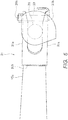
FIG. 6 is an enlarged view as seen in the direction of arrow VI inFIG. 4 ; -
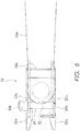
FIG. 7 illustrates the positional relationship between right andleft insertion holes -
FIG. 8 is a side view illustrating a state wherejib 15 is suspended fromboom leading end 14a; -
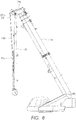
FIG. 9 is a front view illustrating the state wherejib 15 is suspended fromboom leading end 14a; and -
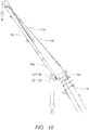
FIG. 10 is a side view illustrating a state wherejib 15 is projected. - In the following, an embodiment of the present invention will be described with reference to the drawings.
- A jib connection structure according to one embodiment of the invention is applied, for example, to mobile crane C as illustrated in
FIG. 1 . The jib connection structure according to the embodiment, however, is not limited to mobile crane C as illustrated inFIG. 1 and can be applied to different cranes. - To begin with, the basic structure of mobile crane C will be described.
- Reference numeral 11 in
FIG. 1 indicates a traveling chassis provided with wheels for traveling. Slewingbase 12 is mounted on chassis 11 in such a manner as to be able to slew 360 degrees in the horizontal plane by a slewing motor.Slewing base 12 is provided with operator'scab 13. -
Boom 14 is attached to slewingbase 12 such thatboom 14 can be freely elevated and lowered. A base end ofboom 14 is pivotally supported by a pin on slewingbase 12. A boom elevating cylinder is attached betweenboom 14 andslewing base 12.Boom 14 is elevated when the boom elevating cylinder is extended, and lowered when the boom elevating cylinder is retracted. Boom 14 is a telescopically designed multi-section boom and is extended or retracted by a telescopic cylinder. - A wire rope provided with a hook (not illustrated) is suspended from leading
end 14a ofboom 14, and is guided alongboom 14 to slewingbase 12 and wound around a winch. The winch is driven to rotate forward and reverse by a hoist motor, to wind up and pay out the wire rope, thereby allowing the hook to be moved up and down. - Combination of slewing of
slewing base 12; elevating, lowering, extending, and retracting ofboom 14; and moving up and down of the hook allows loading and unloading in a three-dimensional space. - Further, mobile crane C is provided with
jib 15. Jib 15 as a whole is an elongated bar member,base end 15a of which is bifurcated. Jib 15 is employed for achieving a lifting height and/or operating radius still greater than a lifting height and/or operating radius of the boom length of fully extendedboom 14. Whenjib 15 is not used,jib 15 is stowed along a side of boom 14 (seeFIG. 1 ). Whenjib 15 is used,base end 15a ofjib 15 is connected to leadingend 14a ofboom 14, andjib 15 is projected forward from boom 14 (seeFIG. 10 ). - In the following, the jib connection structure of the embodiment will be described.
- The jib connection structure of the embodiment is a structure for connecting leading
end 14a of boom 14 (hereinafter referred to as "boom leading end 14a") tobase end 15a of jib 15 (hereinafter referred to as "jib base end 15a") in mobile crane C as described above. -
FIGS. 2 and3 are side and bottom views illustrating a state wherejib 15 is placed in a lower holding position in whichjib 15 is placed along the bottom ofboom 14. As will be described below, in a jib projection/stowage operation,boom leading end 14a is connected to/disconnected fromjib base end 15a in the state wherejib 15 is placed in the lower holding position. - As illustrated in
FIG. 3 , in the state wherejib 15 is placed in the lower holding position,jib 15 is in an offset placement in whichjib base end 15a is located atboom leading end 14a, and a leading end ofjib 15 is located laterally fromboom 14. In this respect, the leading end ofjib 15 is located on the opposite side of operator'scab 13 with respect toboom 14. Hereinafter, in the offset placement, the side on which the leading end ofjib 15 is located is referred to as the left side, and the opposite side thereto (the side of operator's cab 13) is referred to as the right side. However, an embodiment in which the right and left sides are reversed is possible. - As illustrated in
FIG. 4 ,boom leading end 14a is provided withjib connection shafts boom leading end 14a. Right and leftjib connection shafts base end 15a are provided with jib baseend engagement portions - As illustrated in
FIG. 5 , right jib baseend engagement portion 31 is formed to have a U-shape composed of a pair ofarms 31a andbottom portion 31b connecting base parts of the arms. The U-shape of jib baseend engagement portion 31 has an inner diameter slightly greater than an outer diameter of rightjib connection shaft 21. As a result,jib connection shaft 21 can be fitted between the pair ofarms 31a. In the meantime,bottom portion 31b is a member in which the inner surface ofbottom portion 31b, in a state wherejib 15 is projected, makes contact withjib connection shaft 21 so as to transmit force acting onjib 15 tojib connection shaft 21. -
Insertion holes 31h are formed in leading ends of the pair ofarms 31a.Jib connection shaft 21 is prevented from slipping off by fittingjib connection shaft 21 into jib baseend engagement portion 31 and insertingpin 33 intoinsertion holes 31h. Jib baseend engagement portion 31 can thus be connected tojib connection shaft 21. - As illustrated in
FIG. 6 , left jib baseend engagement portion 32 is formed to have a U-shape composed of a pair ofarms 32a andbottom portion 32b connecting base parts of the arms. The U-shape of jib baseend engagement portion 32 has an inner diameter slightly greater than an outer diameter of leftjib connection shaft 22.Jib connection shaft 22 can thus be fitted between the pair ofarms 32a. In the meantime,bottom portion 32b is a member in which the inner surface ofbottom portion 32b, in the state wherejib 15 is projected, makes contact withjib connection shaft 22 so as to transmit force acting onjib 15 tojib connection shaft 22. - Sides of
arms 32a are each provided withextension plates 32c, withextension plates 32c projecting outwardly. Theseextension plates 32c are provided withinsertion holes 32h.Jib connection shaft 22 is prevented from slipping off by fittingjib connection shaft 22 into jib baseend engagement portion 32 and insertingpin 34 intoinsertion holes 32h. Jib baseend engagement portion 32 can thus be connected tojib connection shaft 22. - As illustrated in
FIG. 4 , left jib baseend engagement portion 32 is provided withextension plates 32c, andextension plates 32c are provided withinsertion holes 32h.Insertion holes 32h are thus placed laterally outwardly frombottom portion 32b on which a load is applied in the state wherejib 15 is projected. - The positional relationship between right and left
insertion holes pins 33, 34) will be described with reference toFIG. 7 . - In
FIG. 7 , long dashed double-dotted line O represents the central axis ofjib 15, and point G represents a center of gravity ofjib 15. Long dashed short dashed line L represents a line that connects right and leftinsertion holes - P1 represents a plane perpendicular to central axis O of
jib 15. Plane P1 is perpendicular to the plane of the paper, and thus illustrated by a line inFIG. 7 . Line L connecting right and leftinsertion holes insertion holes jib connection shafts jib 15 is placed laterally fromboom 14. Accordingly, in a state wherejib connection shafts end engagement portions jib 15 is placed laterally from boom 14 (seeFIG. 3 ), pins 33, 34 can be inserted intoinsertion holes jib connection shafts - P2 represents a plane perpendicular to line L, including
right insertion holes 31h. P3 represents a plane perpendicular to line L, includingleft insertion holes 32h. Planes P2, P3 are perpendicular to the plane of the paper, and thus illustrated by lines inFIG. 7 . Center of gravity G ofjib 15 lies between these two planes P2, P3. Accordingly, right and leftpins jib connection shafts jib 15 is suspended fromboom leading end 14a as will be described below. That is,jib 15 is suspended at two points. Meanwhile, in the state wherejib 15 is suspended fromboom leading end 14a, planes P2, P3 are provided as vertical planes. - Suppose that left
insertion holes 32h are located at point H. P4 represents a plane perpendicular to line L, including point H. In this case, center of gravity G ofjib 15 lies outside two planes P2, P4. Therefore, whenjib 15 is suspended fromboom leading end 14a, the moment acts about point H to rotatejib 15. As a result, only leftpin 34 is locked to jib connection shat 22. That is,jib 15 is suspended at one point. The position of point H corresponds, for example, to the position of the leading end ofarm 32a of jib baseend engagement portion 32. This is the reason for the state where a jib in a conventional jib connection structure is suspended at one point. - In particular, in the case of large cranes,
jib 15 is long, so that the offset placement causes center of gravity G to be deviated widely laterally and lie outside right and leftpins jib 15 to increase its stiffness causes center of gravity G to move to the side of the leading end ofjib 15. Placing a hydraulic cylinder for tilting and/or extending or retractingjib 15 on the leading end ofjib 15 in an attempt at labor-saving also causes center of gravity G to move to the side of the leading end ofjib 15. Also in a case where center of gravity G lies on the side of the leading end ofjib 15 in this way, the offset placement causes center of gravity G to lie outside right and leftpins - In contrast, in the embodiment,
insertion holes 32h on one side are placed outwardly laterally, so that center of gravity G lies inside right and leftpins jib 15 is suspended fromboom leading end 14a,jib 15 is suspended at two points. - In the following, a jib projection operation will be described.
- (1) As illustrated in
FIG. 1 , in a state wherejib 15 is in a stowed position,jib 15 is stowed along a side ofboom 14. - (2) Firstly,
boom 14 is slightly extended. Subsequently,jib 15 is moved to the lower holding position in which jib 15 is placed along the bottom ofboom 14.Jib 15 is supported by firstjib supporting member 16 and secondjib supporting member 17. Firstjib supporting member 16 is provided withhydraulic cylinder 16a.Jib 15 can be turned to the lower holding position by extendinghydraulic cylinder 16a.Boom 14 is then fully retracted. Accordingly, the state as illustrated inFIGS. 2 and3 is achieved. In this operation,jib connection shafts end engagement portions FIG. 4 . - (3) Pins 33, 34 are then inserted into
insertion holes end engagement portions jib connection shafts Tension rod 15b provided onjib 15 is also connected. - At this stage,
jib 15 is in the offset placement in which jibbase end 15a is located atboom leading end 14a, and the leading end ofjib 15 is located laterally fromboom 14. As described above, line L connecting right and leftinsertion holes jib 15. Therefore, pins 33, 34 can be inserted intoinsertion holes jib connection shafts - (4)
Boom 14 is then elevated. Subsequently, whenboom 14 is slightly extended, firstjib supporting member 16 and secondjib supporting member 17 are disconnected. Then, as illustrated inFIGS. 8 and9 ,jib 15 rotates aboutjib connection shafts boom leading end 14a. - As described above, center of gravity G of the jib lies between two planes perpendicular to line L connecting right and left
insertion holes respective insertion holes jib 15 is suspended fromboom leading end 14a, center of gravity G ofjib 15 comes to lie between two vertical planes P2, P3 includingrespective pins pins jib connection shafts jib 15 is suspended at two points. As a result,jib 15 is restrained from swinging sideways, and the jib projection operation is easily carried out. - (5)
Tilt cylinder 15c is mounted onjib 15. A rod oftilt cylinder 15c is connected totension rod 15b. - When
tilt cylinder 15c is extended, tension can be generated ontension rod 15b, andjib 15 can be projected forward fromjib connection shafts FIG. 10 illustrates a state wheretilt cylinder 15c is fully extended, in which jib 15 is in substantially straight alignment withboom 14. - When
jib 15 is projected,bottom portions end engagement portions jib connection shafts jib 15 is transmitted frombottom portions end engagement portions jib connection shafts pins - A jib stowage operation is carried out in a procedure reverse to the jib projection operation. Also in the jib stowage operation,
jib 15 is suspended fromboom leading end 14a in the middle of the jib stowage operation (seeFIGS. 8 and9 ). Also in this case, right and leftpins jib connection shafts jib 15 is suspended at two points. As a result,jib 15 is restrained from swinging sideways, and the jib stowage operation is easily carried out. - In the meantime, the distance between right and left
insertion holes left insertion holes 32h laterally outwardly fromboom 14. This makes it possible for center of gravity G ofjib 15 to lie inside right and leftpins jib 15 to be supported at two points even in the state wherejib 15 is suspended fromboom leading end 14a. - In order to achieve similar effects, it may also be considered to widen the bifurcated shape of jib
base end 15a. In this case, however, the distance betweenbottom portions end engagement portions jib connection shafts 21, 22 (portions connected to jibbase end 15a) and contact points ofjib connection shafts bottom portions end engagement portions jib connection shafts - Further, in the case where
jib base end 15a is widened,jib base end 15a in a stowed position protrudes from the bottom ofboom 14, to obstruct the view of the operator during vehicle travel. - In contrast, in the embodiment, said problems do not arise since the distance between right and left
insertion holes base end 15a. In the meantime, pins 33, 34 only support the weight ofjib 15 whilejib 15 is suspended fromboom leading end 14a in the jib projection/stowage operation. For this reason, without an excessive load being caused, even if the width between right and leftpins jib connection shafts - Increasing the distance between right and left
insertion holes jib 15. For example, the jib can be longer, and the diameter of the component members can also be increased in order to increase the stiffness. Further, a hydraulic cylinder for tilting and/or extending or retractingjib 15 can be placed on the leading end ofjib 15. -
- 14 Boom
- 14a Boom leading end
- 15 Jib
- 15a Jib base end
- 21, 22 Jib connection shaft
- 31, 32 Jib base end engagement portion
- 32c Extension plate
- 31h, 32h Insertion hole
- 33, 34 Pin
Claims (2)
- A jib connection structure being a connection structure between a leading end of a boom and a base end of a jib, the jib connection structure comprising:a jib connection shaft horizontally projecting in both lateral directions of the leading end of the boom; andjib base end engagement portions provided at respective ends of the bifurcated base end of the jib, whereinthe jib base end engagement portions are U-shaped into which the jib connection shaft is allowed to be fitted, and include insertion holes for insertion of pins, the pins being intended for preventing slipping off of the jib connection shaft;the insertion holes in one of the jib base end engagement portions are placed laterally outwardly from a U-shaped bottom portion; andthe insertion holes are located at a position at which the pins are allowed to be inserted into the insertion holes in a state where the jib connection shaft is fitted into the jib base end engagement portions and a leading end of the jib is placed laterally from the boom, and at which the inserted right and left pins are locked to the jib connection shaft in a state where the jib is suspended from the leading end of the boom.
- A jib connection structure being a connection structure between a leading end of a boom and a base end of a jib, the jib connection structure comprising:a jib connection shaft horizontally projecting in both lateral directions of the leading end of the boom; andjib base end engagement portions provided at respective ends of the bifurcated base end of the jib, whereinthe jib base end engagement portions are U-shaped into which the jib connection shaft is allowed to be fitted, and include insertion holes for insertion of pins, the pins being intended for preventing slipping off of the jib connection shaft;the insertion holes in one of the jib base end engagement portions is placed laterally outwardly from a U-shaped bottom portion;a line that connects the right and left insertion holes is inclined with respect to a plane perpendicular to a central axis of the jib; anda center of gravity of the jib lies between two planes perpendicular to the line connecting the right and left insertion holes, the two planes including the respective insertion holes.
Applications Claiming Priority (2)
| Application Number | Priority Date | Filing Date | Title |
|---|---|---|---|
| JP2015057900A JP6531448B2 (en) | 2015-03-20 | 2015-03-20 | Jib connection structure |
| PCT/JP2015/005380 WO2016151647A1 (en) | 2015-03-20 | 2015-10-27 | Jib connection structure |
Publications (3)
| Publication Number | Publication Date |
|---|---|
| EP3272694A1 true EP3272694A1 (en) | 2018-01-24 |
| EP3272694A4 EP3272694A4 (en) | 2018-11-21 |
| EP3272694B1 EP3272694B1 (en) | 2020-02-26 |
Family
ID=56977571
Family Applications (1)
| Application Number | Title | Priority Date | Filing Date |
|---|---|---|---|
| EP15886204.5A Active EP3272694B1 (en) | 2015-03-20 | 2015-10-27 | Jib connection structure |
Country Status (6)
| Country | Link |
|---|---|
| US (1) | US10287144B2 (en) |
| EP (1) | EP3272694B1 (en) |
| JP (1) | JP6531448B2 (en) |
| KR (1) | KR101929177B1 (en) |
| CN (1) | CN107428517B (en) |
| WO (1) | WO2016151647A1 (en) |
Families Citing this family (4)
| Publication number | Priority date | Publication date | Assignee | Title |
|---|---|---|---|---|
| JP6520270B2 (en) * | 2015-03-20 | 2019-05-29 | 株式会社タダノ | Jib connection structure |
| JP6686570B2 (en) * | 2016-03-15 | 2020-04-22 | 株式会社タダノ | Jib connection structure |
| US10710847B2 (en) * | 2016-06-17 | 2020-07-14 | Maeda Seisakusho Co., Ltd. | Mobile crane |
| JP7375379B2 (en) * | 2019-08-29 | 2023-11-08 | コベルコ建機株式会社 | Auxiliary sheave device |
Family Cites Families (23)
| Publication number | Priority date | Publication date | Assignee | Title |
|---|---|---|---|---|
| US4155464A (en) * | 1976-12-15 | 1979-05-22 | Caterpillar Tractor Co. | Offset jib for cranes |
| US4658972A (en) * | 1982-01-26 | 1987-04-21 | Kabushiki Kaisha Kobe Seiko Sho | Method for stretching and folding extension jib in wheeled type crane |
| JPH0328069Y2 (en) * | 1987-04-28 | 1991-06-17 | ||
| JPH02127693A (en) | 1988-11-08 | 1990-05-16 | Casio Comput Co Ltd | sound source device |
| JPH078548Y2 (en) * | 1989-03-27 | 1995-03-01 | 株式会社タダノ | Jib storage device for vehicle-mounted crane |
| US4953724A (en) * | 1989-06-29 | 1990-09-04 | Kabushiki Kaisha Kobe Seiko Sho | Jib stretching and folding device |
| CA2015519C (en) * | 1989-08-10 | 1994-09-27 | Yukio Koizumi | Jib stretching and folding device for crane |
| FR2661665B1 (en) * | 1990-05-03 | 1992-09-04 | Ppm Sa | HANDLING BOOM COMPRISING A MAIN BOOM AND A COMPLEMENTARY BOOM. |
| US5193698A (en) * | 1990-09-13 | 1993-03-16 | Kabushiki Kaisha Kobe Seiko Sho | Jib stretching and folding device for use in a crane |
| US5111945A (en) * | 1991-09-13 | 1992-05-12 | Kidde Industries, Inc. | Boom extension alignment device |
| JP2883860B2 (en) * | 1996-04-05 | 1999-04-19 | 株式会社小松製作所 | Crane jib overhang and storage device and its overhang and storage method |
| JPH1111878A (en) | 1997-06-24 | 1999-01-19 | Tadano Ltd | Jib accommodating device for on-vehicle crane |
| JP2003226486A (en) * | 2002-02-01 | 2003-08-12 | Tadano Ltd | Jib storing device of truck crane |
| JP4683971B2 (en) * | 2005-03-25 | 2011-05-18 | 株式会社タダノ | Jib connection structure of mobile crane |
| JP2009149438A (en) * | 2007-11-29 | 2009-07-09 | Manitowoc Crane Companies Ltd | Connection system for crane boom segment |
| JP5422367B2 (en) * | 2009-12-22 | 2014-02-19 | 株式会社加藤製作所 | Crane jib overhanging device |
| JP2012166920A (en) * | 2011-02-15 | 2012-09-06 | Tadano Ltd | Boom telescopic device |
| US8813981B2 (en) * | 2011-03-21 | 2014-08-26 | Oshkosh Corporation | Anti-two block system for a crane assembly |
| EP2746214B1 (en) * | 2012-12-20 | 2016-04-27 | Manitowoc Crane Companies, LLC | Column connector system |
| JP6004537B2 (en) * | 2013-03-18 | 2016-10-12 | コベルコ建機株式会社 | jib |
| US10053340B2 (en) * | 2014-01-20 | 2018-08-21 | Manitowoc Crane Companies, Llc | System and method for connecting a crane suspension assembly to a support column |
| CN203754305U (en) * | 2014-01-27 | 2014-08-06 | 合肥鱼竿神吊机械设备有限公司 | Telescopic boom lever of small crane |
| DE102015120350B3 (en) * | 2015-11-24 | 2017-05-24 | Terex Global Gmbh | Mobile crane for bending a main boom extension relative to a main boom of a mobile crane |
-
2015
- 2015-03-20 JP JP2015057900A patent/JP6531448B2/en active Active
- 2015-10-27 WO PCT/JP2015/005380 patent/WO2016151647A1/en not_active Ceased
- 2015-10-27 KR KR1020177008229A patent/KR101929177B1/en active Active
- 2015-10-27 CN CN201580062581.4A patent/CN107428517B/en active Active
- 2015-10-27 US US15/521,076 patent/US10287144B2/en active Active
- 2015-10-27 EP EP15886204.5A patent/EP3272694B1/en active Active
Also Published As
| Publication number | Publication date |
|---|---|
| KR20170082150A (en) | 2017-07-13 |
| EP3272694A4 (en) | 2018-11-21 |
| EP3272694B1 (en) | 2020-02-26 |
| JP2016175753A (en) | 2016-10-06 |
| WO2016151647A1 (en) | 2016-09-29 |
| CN107428517A (en) | 2017-12-01 |
| KR101929177B1 (en) | 2018-12-13 |
| JP6531448B2 (en) | 2019-06-19 |
| CN107428517B (en) | 2019-02-19 |
| US10287144B2 (en) | 2019-05-14 |
| US20180037446A1 (en) | 2018-02-08 |
Similar Documents
| Publication | Publication Date | Title |
|---|---|---|
| US9738497B2 (en) | Jib attachment/detachment mechanism | |
| EP3272694B1 (en) | Jib connection structure | |
| EP3272695B1 (en) | Jib connection structure | |
| US10654694B2 (en) | Cylinder retention device | |
| US10640341B2 (en) | Method for raising raisable and lowerable member, and crane | |
| US10308486B2 (en) | Overhanging storage mechanism for jib | |
| CN108328490B (en) | Crane boom, crane comprising same and super-lift support arm installation method | |
| US10287143B2 (en) | Overhanging storage mechanism for jib | |
| US10519010B2 (en) | Crane | |
| EP4261175A1 (en) | Upper spreader guide device | |
| CN109689560B (en) | crane | |
| JP6686570B2 (en) | Jib connection structure | |
| JP6443017B2 (en) | Jib attachment / detachment mechanism | |
| JP2012051692A (en) | Mobile crane | |
| EP3992138A1 (en) | Crane | |
| US20220250879A1 (en) | Work vehicle | |
| JP2017095221A (en) | Adaptor |
Legal Events
| Date | Code | Title | Description |
|---|---|---|---|
| STAA | Information on the status of an ep patent application or granted ep patent |
Free format text: STATUS: THE INTERNATIONAL PUBLICATION HAS BEEN MADE |
|
| PUAI | Public reference made under article 153(3) epc to a published international application that has entered the european phase |
Free format text: ORIGINAL CODE: 0009012 |
|
| STAA | Information on the status of an ep patent application or granted ep patent |
Free format text: STATUS: REQUEST FOR EXAMINATION WAS MADE |
|
| 17P | Request for examination filed |
Effective date: 20171018 |
|
| AK | Designated contracting states |
Kind code of ref document: A1 Designated state(s): AL AT BE BG CH CY CZ DE DK EE ES FI FR GB GR HR HU IE IS IT LI LT LU LV MC MK MT NL NO PL PT RO RS SE SI SK SM TR |
|
| AX | Request for extension of the european patent |
Extension state: BA ME |
|
| DAV | Request for validation of the european patent (deleted) | ||
| DAX | Request for extension of the european patent (deleted) | ||
| A4 | Supplementary search report drawn up and despatched |
Effective date: 20181023 |
|
| RIC1 | Information provided on ipc code assigned before grant |
Ipc: B66C 23/70 20060101AFI20181017BHEP Ipc: B66C 23/66 20060101ALI20181017BHEP |
|
| RIC1 | Information provided on ipc code assigned before grant |
Ipc: B66C 23/66 20060101ALI20190712BHEP Ipc: B66C 23/70 20060101AFI20190712BHEP |
|
| GRAP | Despatch of communication of intention to grant a patent |
Free format text: ORIGINAL CODE: EPIDOSNIGR1 |
|
| STAA | Information on the status of an ep patent application or granted ep patent |
Free format text: STATUS: GRANT OF PATENT IS INTENDED |
|
| INTG | Intention to grant announced |
Effective date: 20190916 |
|
| GRAS | Grant fee paid |
Free format text: ORIGINAL CODE: EPIDOSNIGR3 |
|
| GRAA | (expected) grant |
Free format text: ORIGINAL CODE: 0009210 |
|
| STAA | Information on the status of an ep patent application or granted ep patent |
Free format text: STATUS: THE PATENT HAS BEEN GRANTED |
|
| AK | Designated contracting states |
Kind code of ref document: B1 Designated state(s): AL AT BE BG CH CY CZ DE DK EE ES FI FR GB GR HR HU IE IS IT LI LT LU LV MC MK MT NL NO PL PT RO RS SE SI SK SM TR |
|
| REG | Reference to a national code |
Ref country code: GB Ref legal event code: FG4D |
|
| REG | Reference to a national code |
Ref country code: CH Ref legal event code: EP |
|
| REG | Reference to a national code |
Ref country code: AT Ref legal event code: REF Ref document number: 1237408 Country of ref document: AT Kind code of ref document: T Effective date: 20200315 |
|
| REG | Reference to a national code |
Ref country code: IE Ref legal event code: FG4D |
|
| REG | Reference to a national code |
Ref country code: DE Ref legal event code: R096 Ref document number: 602015047959 Country of ref document: DE |
|
| PG25 | Lapsed in a contracting state [announced via postgrant information from national office to epo] |
Ref country code: FI Free format text: LAPSE BECAUSE OF FAILURE TO SUBMIT A TRANSLATION OF THE DESCRIPTION OR TO PAY THE FEE WITHIN THE PRESCRIBED TIME-LIMIT Effective date: 20200226 Ref country code: RS Free format text: LAPSE BECAUSE OF FAILURE TO SUBMIT A TRANSLATION OF THE DESCRIPTION OR TO PAY THE FEE WITHIN THE PRESCRIBED TIME-LIMIT Effective date: 20200226 Ref country code: NO Free format text: LAPSE BECAUSE OF FAILURE TO SUBMIT A TRANSLATION OF THE DESCRIPTION OR TO PAY THE FEE WITHIN THE PRESCRIBED TIME-LIMIT Effective date: 20200526 |
|
| REG | Reference to a national code |
Ref country code: NL Ref legal event code: MP Effective date: 20200226 |
|
| REG | Reference to a national code |
Ref country code: LT Ref legal event code: MG4D |
|
| PG25 | Lapsed in a contracting state [announced via postgrant information from national office to epo] |
Ref country code: BG Free format text: LAPSE BECAUSE OF FAILURE TO SUBMIT A TRANSLATION OF THE DESCRIPTION OR TO PAY THE FEE WITHIN THE PRESCRIBED TIME-LIMIT Effective date: 20200526 Ref country code: HR Free format text: LAPSE BECAUSE OF FAILURE TO SUBMIT A TRANSLATION OF THE DESCRIPTION OR TO PAY THE FEE WITHIN THE PRESCRIBED TIME-LIMIT Effective date: 20200226 Ref country code: IS Free format text: LAPSE BECAUSE OF FAILURE TO SUBMIT A TRANSLATION OF THE DESCRIPTION OR TO PAY THE FEE WITHIN THE PRESCRIBED TIME-LIMIT Effective date: 20200626 Ref country code: GR Free format text: LAPSE BECAUSE OF FAILURE TO SUBMIT A TRANSLATION OF THE DESCRIPTION OR TO PAY THE FEE WITHIN THE PRESCRIBED TIME-LIMIT Effective date: 20200527 Ref country code: SE Free format text: LAPSE BECAUSE OF FAILURE TO SUBMIT A TRANSLATION OF THE DESCRIPTION OR TO PAY THE FEE WITHIN THE PRESCRIBED TIME-LIMIT Effective date: 20200226 Ref country code: LV Free format text: LAPSE BECAUSE OF FAILURE TO SUBMIT A TRANSLATION OF THE DESCRIPTION OR TO PAY THE FEE WITHIN THE PRESCRIBED TIME-LIMIT Effective date: 20200226 |
|
| PG25 | Lapsed in a contracting state [announced via postgrant information from national office to epo] |
Ref country code: NL Free format text: LAPSE BECAUSE OF FAILURE TO SUBMIT A TRANSLATION OF THE DESCRIPTION OR TO PAY THE FEE WITHIN THE PRESCRIBED TIME-LIMIT Effective date: 20200226 |
|
| PG25 | Lapsed in a contracting state [announced via postgrant information from national office to epo] |
Ref country code: ES Free format text: LAPSE BECAUSE OF FAILURE TO SUBMIT A TRANSLATION OF THE DESCRIPTION OR TO PAY THE FEE WITHIN THE PRESCRIBED TIME-LIMIT Effective date: 20200226 Ref country code: EE Free format text: LAPSE BECAUSE OF FAILURE TO SUBMIT A TRANSLATION OF THE DESCRIPTION OR TO PAY THE FEE WITHIN THE PRESCRIBED TIME-LIMIT Effective date: 20200226 Ref country code: SM Free format text: LAPSE BECAUSE OF FAILURE TO SUBMIT A TRANSLATION OF THE DESCRIPTION OR TO PAY THE FEE WITHIN THE PRESCRIBED TIME-LIMIT Effective date: 20200226 Ref country code: DK Free format text: LAPSE BECAUSE OF FAILURE TO SUBMIT A TRANSLATION OF THE DESCRIPTION OR TO PAY THE FEE WITHIN THE PRESCRIBED TIME-LIMIT Effective date: 20200226 Ref country code: RO Free format text: LAPSE BECAUSE OF FAILURE TO SUBMIT A TRANSLATION OF THE DESCRIPTION OR TO PAY THE FEE WITHIN THE PRESCRIBED TIME-LIMIT Effective date: 20200226 Ref country code: SK Free format text: LAPSE BECAUSE OF FAILURE TO SUBMIT A TRANSLATION OF THE DESCRIPTION OR TO PAY THE FEE WITHIN THE PRESCRIBED TIME-LIMIT Effective date: 20200226 Ref country code: CZ Free format text: LAPSE BECAUSE OF FAILURE TO SUBMIT A TRANSLATION OF THE DESCRIPTION OR TO PAY THE FEE WITHIN THE PRESCRIBED TIME-LIMIT Effective date: 20200226 Ref country code: LT Free format text: LAPSE BECAUSE OF FAILURE TO SUBMIT A TRANSLATION OF THE DESCRIPTION OR TO PAY THE FEE WITHIN THE PRESCRIBED TIME-LIMIT Effective date: 20200226 Ref country code: PT Free format text: LAPSE BECAUSE OF FAILURE TO SUBMIT A TRANSLATION OF THE DESCRIPTION OR TO PAY THE FEE WITHIN THE PRESCRIBED TIME-LIMIT Effective date: 20200719 |
|
| REG | Reference to a national code |
Ref country code: AT Ref legal event code: MK05 Ref document number: 1237408 Country of ref document: AT Kind code of ref document: T Effective date: 20200226 |
|
| REG | Reference to a national code |
Ref country code: DE Ref legal event code: R097 Ref document number: 602015047959 Country of ref document: DE |
|
| PLBE | No opposition filed within time limit |
Free format text: ORIGINAL CODE: 0009261 |
|
| STAA | Information on the status of an ep patent application or granted ep patent |
Free format text: STATUS: NO OPPOSITION FILED WITHIN TIME LIMIT |
|
| PG25 | Lapsed in a contracting state [announced via postgrant information from national office to epo] |
Ref country code: IT Free format text: LAPSE BECAUSE OF FAILURE TO SUBMIT A TRANSLATION OF THE DESCRIPTION OR TO PAY THE FEE WITHIN THE PRESCRIBED TIME-LIMIT Effective date: 20200226 Ref country code: AT Free format text: LAPSE BECAUSE OF FAILURE TO SUBMIT A TRANSLATION OF THE DESCRIPTION OR TO PAY THE FEE WITHIN THE PRESCRIBED TIME-LIMIT Effective date: 20200226 |
|
| 26N | No opposition filed |
Effective date: 20201127 |
|
| PG25 | Lapsed in a contracting state [announced via postgrant information from national office to epo] |
Ref country code: PL Free format text: LAPSE BECAUSE OF FAILURE TO SUBMIT A TRANSLATION OF THE DESCRIPTION OR TO PAY THE FEE WITHIN THE PRESCRIBED TIME-LIMIT Effective date: 20200226 Ref country code: SI Free format text: LAPSE BECAUSE OF FAILURE TO SUBMIT A TRANSLATION OF THE DESCRIPTION OR TO PAY THE FEE WITHIN THE PRESCRIBED TIME-LIMIT Effective date: 20200226 |
|
| REG | Reference to a national code |
Ref country code: CH Ref legal event code: PL |
|
| GBPC | Gb: european patent ceased through non-payment of renewal fee |
Effective date: 20201027 |
|
| PG25 | Lapsed in a contracting state [announced via postgrant information from national office to epo] |
Ref country code: MC Free format text: LAPSE BECAUSE OF FAILURE TO SUBMIT A TRANSLATION OF THE DESCRIPTION OR TO PAY THE FEE WITHIN THE PRESCRIBED TIME-LIMIT Effective date: 20200226 Ref country code: LU Free format text: LAPSE BECAUSE OF NON-PAYMENT OF DUE FEES Effective date: 20201027 |
|
| REG | Reference to a national code |
Ref country code: BE Ref legal event code: MM Effective date: 20201031 |
|
| PG25 | Lapsed in a contracting state [announced via postgrant information from national office to epo] |
Ref country code: FR Free format text: LAPSE BECAUSE OF NON-PAYMENT OF DUE FEES Effective date: 20201031 |
|
| PG25 | Lapsed in a contracting state [announced via postgrant information from national office to epo] |
Ref country code: LI Free format text: LAPSE BECAUSE OF NON-PAYMENT OF DUE FEES Effective date: 20201031 Ref country code: GB Free format text: LAPSE BECAUSE OF NON-PAYMENT OF DUE FEES Effective date: 20201027 Ref country code: BE Free format text: LAPSE BECAUSE OF NON-PAYMENT OF DUE FEES Effective date: 20201031 Ref country code: CH Free format text: LAPSE BECAUSE OF NON-PAYMENT OF DUE FEES Effective date: 20201031 |
|
| PG25 | Lapsed in a contracting state [announced via postgrant information from national office to epo] |
Ref country code: IE Free format text: LAPSE BECAUSE OF NON-PAYMENT OF DUE FEES Effective date: 20201027 |
|
| PG25 | Lapsed in a contracting state [announced via postgrant information from national office to epo] |
Ref country code: TR Free format text: LAPSE BECAUSE OF FAILURE TO SUBMIT A TRANSLATION OF THE DESCRIPTION OR TO PAY THE FEE WITHIN THE PRESCRIBED TIME-LIMIT Effective date: 20200226 Ref country code: MT Free format text: LAPSE BECAUSE OF FAILURE TO SUBMIT A TRANSLATION OF THE DESCRIPTION OR TO PAY THE FEE WITHIN THE PRESCRIBED TIME-LIMIT Effective date: 20200226 Ref country code: CY Free format text: LAPSE BECAUSE OF FAILURE TO SUBMIT A TRANSLATION OF THE DESCRIPTION OR TO PAY THE FEE WITHIN THE PRESCRIBED TIME-LIMIT Effective date: 20200226 |
|
| PG25 | Lapsed in a contracting state [announced via postgrant information from national office to epo] |
Ref country code: MK Free format text: LAPSE BECAUSE OF FAILURE TO SUBMIT A TRANSLATION OF THE DESCRIPTION OR TO PAY THE FEE WITHIN THE PRESCRIBED TIME-LIMIT Effective date: 20200226 Ref country code: AL Free format text: LAPSE BECAUSE OF FAILURE TO SUBMIT A TRANSLATION OF THE DESCRIPTION OR TO PAY THE FEE WITHIN THE PRESCRIBED TIME-LIMIT Effective date: 20200226 |
|
| PGFP | Annual fee paid to national office [announced via postgrant information from national office to epo] |
Ref country code: DE Payment date: 20251020 Year of fee payment: 11 |