EP3272650A1 - Horizontal stabilizer trim actuator systems and methods - Google Patents
Horizontal stabilizer trim actuator systems and methods Download PDFInfo
- Publication number
- EP3272650A1 EP3272650A1 EP17180456.0A EP17180456A EP3272650A1 EP 3272650 A1 EP3272650 A1 EP 3272650A1 EP 17180456 A EP17180456 A EP 17180456A EP 3272650 A1 EP3272650 A1 EP 3272650A1
- Authority
- EP
- European Patent Office
- Prior art keywords
- hydraulic
- directional
- sov
- path
- hydraulic fluid
- Prior art date
- Legal status (The legal status is an assumption and is not a legal conclusion. Google has not performed a legal analysis and makes no representation as to the accuracy of the status listed.)
- Granted
Links
Images




Classifications
-
- B—PERFORMING OPERATIONS; TRANSPORTING
- B64—AIRCRAFT; AVIATION; COSMONAUTICS
- B64C—AEROPLANES; HELICOPTERS
- B64C13/00—Control systems or transmitting systems for actuating flying-control surfaces, lift-increasing flaps, air brakes, or spoilers
- B64C13/24—Transmitting means
- B64C13/38—Transmitting means with power amplification
- B64C13/40—Transmitting means with power amplification using fluid pressure
-
- B—PERFORMING OPERATIONS; TRANSPORTING
- B64—AIRCRAFT; AVIATION; COSMONAUTICS
- B64C—AEROPLANES; HELICOPTERS
- B64C5/00—Stabilising surfaces
- B64C5/02—Tailplanes
-
- B—PERFORMING OPERATIONS; TRANSPORTING
- B64—AIRCRAFT; AVIATION; COSMONAUTICS
- B64C—AEROPLANES; HELICOPTERS
- B64C5/00—Stabilising surfaces
- B64C5/10—Stabilising surfaces adjustable
-
- F—MECHANICAL ENGINEERING; LIGHTING; HEATING; WEAPONS; BLASTING
- F15—FLUID-PRESSURE ACTUATORS; HYDRAULICS OR PNEUMATICS IN GENERAL
- F15B—SYSTEMS ACTING BY MEANS OF FLUIDS IN GENERAL; FLUID-PRESSURE ACTUATORS, e.g. SERVOMOTORS; DETAILS OF FLUID-PRESSURE SYSTEMS, NOT OTHERWISE PROVIDED FOR
- F15B11/00—Servomotor systems without provision for follow-up action; Circuits therefor
- F15B11/08—Servomotor systems without provision for follow-up action; Circuits therefor with only one servomotor
-
- F—MECHANICAL ENGINEERING; LIGHTING; HEATING; WEAPONS; BLASTING
- F15—FLUID-PRESSURE ACTUATORS; HYDRAULICS OR PNEUMATICS IN GENERAL
- F15B—SYSTEMS ACTING BY MEANS OF FLUIDS IN GENERAL; FLUID-PRESSURE ACTUATORS, e.g. SERVOMOTORS; DETAILS OF FLUID-PRESSURE SYSTEMS, NOT OTHERWISE PROVIDED FOR
- F15B13/00—Details of servomotor systems ; Valves for servomotor systems
- F15B13/02—Fluid distribution or supply devices characterised by their adaptation to the control of servomotors
- F15B13/04—Fluid distribution or supply devices characterised by their adaptation to the control of servomotors for use with a single servomotor
- F15B13/0401—Valve members; Fluid interconnections therefor
- F15B13/0402—Valve members; Fluid interconnections therefor for linearly sliding valves, e.g. spool valves
-
- F—MECHANICAL ENGINEERING; LIGHTING; HEATING; WEAPONS; BLASTING
- F15—FLUID-PRESSURE ACTUATORS; HYDRAULICS OR PNEUMATICS IN GENERAL
- F15B—SYSTEMS ACTING BY MEANS OF FLUIDS IN GENERAL; FLUID-PRESSURE ACTUATORS, e.g. SERVOMOTORS; DETAILS OF FLUID-PRESSURE SYSTEMS, NOT OTHERWISE PROVIDED FOR
- F15B13/00—Details of servomotor systems ; Valves for servomotor systems
- F15B13/02—Fluid distribution or supply devices characterised by their adaptation to the control of servomotors
- F15B13/04—Fluid distribution or supply devices characterised by their adaptation to the control of servomotors for use with a single servomotor
- F15B13/042—Fluid distribution or supply devices characterised by their adaptation to the control of servomotors for use with a single servomotor operated by fluid pressure
-
- F—MECHANICAL ENGINEERING; LIGHTING; HEATING; WEAPONS; BLASTING
- F15—FLUID-PRESSURE ACTUATORS; HYDRAULICS OR PNEUMATICS IN GENERAL
- F15B—SYSTEMS ACTING BY MEANS OF FLUIDS IN GENERAL; FLUID-PRESSURE ACTUATORS, e.g. SERVOMOTORS; DETAILS OF FLUID-PRESSURE SYSTEMS, NOT OTHERWISE PROVIDED FOR
- F15B2211/00—Circuits for servomotor systems
- F15B2211/30—Directional control
- F15B2211/305—Directional control characterised by the type of valves
- F15B2211/3056—Assemblies of multiple valves
- F15B2211/30565—Assemblies of multiple valves having multiple valves for a single output member, e.g. for creating higher valve function by use of multiple valves like two 2/2-valves replacing a 5/3-valve
-
- F—MECHANICAL ENGINEERING; LIGHTING; HEATING; WEAPONS; BLASTING
- F15—FLUID-PRESSURE ACTUATORS; HYDRAULICS OR PNEUMATICS IN GENERAL
- F15B—SYSTEMS ACTING BY MEANS OF FLUIDS IN GENERAL; FLUID-PRESSURE ACTUATORS, e.g. SERVOMOTORS; DETAILS OF FLUID-PRESSURE SYSTEMS, NOT OTHERWISE PROVIDED FOR
- F15B2211/00—Circuits for servomotor systems
- F15B2211/30—Directional control
- F15B2211/31—Directional control characterised by the positions of the valve element
- F15B2211/3105—Neutral or centre positions
- F15B2211/3111—Neutral or centre positions the pump port being closed in the centre position, e.g. so-called closed centre
-
- F—MECHANICAL ENGINEERING; LIGHTING; HEATING; WEAPONS; BLASTING
- F15—FLUID-PRESSURE ACTUATORS; HYDRAULICS OR PNEUMATICS IN GENERAL
- F15B—SYSTEMS ACTING BY MEANS OF FLUIDS IN GENERAL; FLUID-PRESSURE ACTUATORS, e.g. SERVOMOTORS; DETAILS OF FLUID-PRESSURE SYSTEMS, NOT OTHERWISE PROVIDED FOR
- F15B2211/00—Circuits for servomotor systems
- F15B2211/30—Directional control
- F15B2211/32—Directional control characterised by the type of actuation
- F15B2211/327—Directional control characterised by the type of actuation electrically or electronically
-
- F—MECHANICAL ENGINEERING; LIGHTING; HEATING; WEAPONS; BLASTING
- F15—FLUID-PRESSURE ACTUATORS; HYDRAULICS OR PNEUMATICS IN GENERAL
- F15B—SYSTEMS ACTING BY MEANS OF FLUIDS IN GENERAL; FLUID-PRESSURE ACTUATORS, e.g. SERVOMOTORS; DETAILS OF FLUID-PRESSURE SYSTEMS, NOT OTHERWISE PROVIDED FOR
- F15B2211/00—Circuits for servomotor systems
- F15B2211/30—Directional control
- F15B2211/32—Directional control characterised by the type of actuation
- F15B2211/329—Directional control characterised by the type of actuation actuated by fluid pressure
-
- F—MECHANICAL ENGINEERING; LIGHTING; HEATING; WEAPONS; BLASTING
- F15—FLUID-PRESSURE ACTUATORS; HYDRAULICS OR PNEUMATICS IN GENERAL
- F15B—SYSTEMS ACTING BY MEANS OF FLUIDS IN GENERAL; FLUID-PRESSURE ACTUATORS, e.g. SERVOMOTORS; DETAILS OF FLUID-PRESSURE SYSTEMS, NOT OTHERWISE PROVIDED FOR
- F15B2211/00—Circuits for servomotor systems
- F15B2211/40—Flow control
- F15B2211/41—Flow control characterised by the positions of the valve element
- F15B2211/411—Flow control characterised by the positions of the valve element the positions being discrete
-
- F—MECHANICAL ENGINEERING; LIGHTING; HEATING; WEAPONS; BLASTING
- F15—FLUID-PRESSURE ACTUATORS; HYDRAULICS OR PNEUMATICS IN GENERAL
- F15B—SYSTEMS ACTING BY MEANS OF FLUIDS IN GENERAL; FLUID-PRESSURE ACTUATORS, e.g. SERVOMOTORS; DETAILS OF FLUID-PRESSURE SYSTEMS, NOT OTHERWISE PROVIDED FOR
- F15B2211/00—Circuits for servomotor systems
- F15B2211/40—Flow control
- F15B2211/415—Flow control characterised by the connections of the flow control means in the circuit
- F15B2211/41509—Flow control characterised by the connections of the flow control means in the circuit being connected to a pressure source and a directional control valve
-
- F—MECHANICAL ENGINEERING; LIGHTING; HEATING; WEAPONS; BLASTING
- F15—FLUID-PRESSURE ACTUATORS; HYDRAULICS OR PNEUMATICS IN GENERAL
- F15B—SYSTEMS ACTING BY MEANS OF FLUIDS IN GENERAL; FLUID-PRESSURE ACTUATORS, e.g. SERVOMOTORS; DETAILS OF FLUID-PRESSURE SYSTEMS, NOT OTHERWISE PROVIDED FOR
- F15B2211/00—Circuits for servomotor systems
- F15B2211/40—Flow control
- F15B2211/42—Flow control characterised by the type of actuation
- F15B2211/428—Flow control characterised by the type of actuation actuated by fluid pressure
-
- F—MECHANICAL ENGINEERING; LIGHTING; HEATING; WEAPONS; BLASTING
- F15—FLUID-PRESSURE ACTUATORS; HYDRAULICS OR PNEUMATICS IN GENERAL
- F15B—SYSTEMS ACTING BY MEANS OF FLUIDS IN GENERAL; FLUID-PRESSURE ACTUATORS, e.g. SERVOMOTORS; DETAILS OF FLUID-PRESSURE SYSTEMS, NOT OTHERWISE PROVIDED FOR
- F15B2211/00—Circuits for servomotor systems
- F15B2211/60—Circuit components or control therefor
- F15B2211/63—Electronic controllers
- F15B2211/6303—Electronic controllers using input signals
- F15B2211/634—Electronic controllers using input signals representing a state of a valve
-
- F—MECHANICAL ENGINEERING; LIGHTING; HEATING; WEAPONS; BLASTING
- F15—FLUID-PRESSURE ACTUATORS; HYDRAULICS OR PNEUMATICS IN GENERAL
- F15B—SYSTEMS ACTING BY MEANS OF FLUIDS IN GENERAL; FLUID-PRESSURE ACTUATORS, e.g. SERVOMOTORS; DETAILS OF FLUID-PRESSURE SYSTEMS, NOT OTHERWISE PROVIDED FOR
- F15B2211/00—Circuits for servomotor systems
- F15B2211/70—Output members, e.g. hydraulic motors or cylinders or control therefor
- F15B2211/705—Output members, e.g. hydraulic motors or cylinders or control therefor characterised by the type of output members or actuators
- F15B2211/7058—Rotary output members
-
- F—MECHANICAL ENGINEERING; LIGHTING; HEATING; WEAPONS; BLASTING
- F15—FLUID-PRESSURE ACTUATORS; HYDRAULICS OR PNEUMATICS IN GENERAL
- F15B—SYSTEMS ACTING BY MEANS OF FLUIDS IN GENERAL; FLUID-PRESSURE ACTUATORS, e.g. SERVOMOTORS; DETAILS OF FLUID-PRESSURE SYSTEMS, NOT OTHERWISE PROVIDED FOR
- F15B2211/00—Circuits for servomotor systems
- F15B2211/70—Output members, e.g. hydraulic motors or cylinders or control therefor
- F15B2211/715—Output members, e.g. hydraulic motors or cylinders or control therefor having braking means
-
- F—MECHANICAL ENGINEERING; LIGHTING; HEATING; WEAPONS; BLASTING
- F15—FLUID-PRESSURE ACTUATORS; HYDRAULICS OR PNEUMATICS IN GENERAL
- F15B—SYSTEMS ACTING BY MEANS OF FLUIDS IN GENERAL; FLUID-PRESSURE ACTUATORS, e.g. SERVOMOTORS; DETAILS OF FLUID-PRESSURE SYSTEMS, NOT OTHERWISE PROVIDED FOR
- F15B2211/00—Circuits for servomotor systems
- F15B2211/70—Output members, e.g. hydraulic motors or cylinders or control therefor
- F15B2211/765—Control of position or angle of the output member
-
- Y—GENERAL TAGGING OF NEW TECHNOLOGICAL DEVELOPMENTS; GENERAL TAGGING OF CROSS-SECTIONAL TECHNOLOGIES SPANNING OVER SEVERAL SECTIONS OF THE IPC; TECHNICAL SUBJECTS COVERED BY FORMER USPC CROSS-REFERENCE ART COLLECTIONS [XRACs] AND DIGESTS
- Y02—TECHNOLOGIES OR APPLICATIONS FOR MITIGATION OR ADAPTATION AGAINST CLIMATE CHANGE
- Y02T—CLIMATE CHANGE MITIGATION TECHNOLOGIES RELATED TO TRANSPORTATION
- Y02T50/00—Aeronautics or air transport
- Y02T50/40—Weight reduction
Definitions
- the disclosure relates generally to aircraft control surface systems and more specifically to Horizontal Stabilizer Trim Actuator (HSTA) systems used to control horizontal control surfaces.
- HSTA Horizontal Stabilizer Trim Actuator
- Aircraft often include one or more control surfaces such as, for example, one or more horizontal stabilizers.
- the horizontal stabilizer may be located, for example, at the rear of the aircraft and may include elevator control surfaces that are attached that may be used to change the pitch of the aircraft.
- a Horizontal Stabilizer Trim Actuator (HSTA) may be used to move the horizontal control surface.
- the HSTA may be, for example, a hydraulic system that may actuate the horizontal control surface responsive to commands issued by a controller or pilot of the aircraft.
- the horizontal control surface may be moved to alleviate load on the elevator control surfaces.
- un-commanded or unintended movement of the horizontal stabilizer may not be desirable.
- a HSTA designed to prevent such un-commanded or unintended movement is desirable.
- a system may be disclosed and may include a hydraulic inlet configured to receive pressurized hydraulic fluid, a first hydraulic path fluidically connected to the hydraulic inlet, a second hydraulic path, a hydraulic shutoff apparatus fluidically connected to the first hydraulic path and the second hydraulic path and configured to be switched between a plurality of hydraulic positions wherein at least one of the hydraulic positions allows for the pressurized hydraulic fluid to flow from the first hydraulic path through the hydraulic shutoff apparatus to the second hydraulic path, a directional and rate control apparatus, a third hydraulic path fluidically connected to the directional and rate control apparatus, and a hydraulic motor fluidically connected to the directional and rate control apparatus via the third hydraulic path.
- the directional and rate control apparatus may be configured to be switched between a plurality of directional control positions where at least one of the directional control positions allows for the pressurized hydraulic fluid to flow from the second hydraulic path through the directional and rate control apparatus to the hydraulic motor.
- the hydraulic motor may be configured to turn an output shaft to actuate a control surface of a vehicle responsive to receiving the pressurized hydraulic fluid from the directional and rate control apparatus and configured to be locked responsive to not receiving the pressurized hydraulic fluid from the directional and rate control apparatus.
- a method may be disclosed and may include receiving pressurized hydraulic fluid, flowing the pressurized hydraulic fluid into a hydraulic shutoff apparatus, switching, responsive to the flow of the pressurized hydraulic fluid into the hydraulic shutoff apparatus, the hydraulic shutoff apparatus to a first hydraulic position, flowing the pressurized hydraulic fluid into a directional and rate control apparatus, switching, responsive to the flow of the pressurized hydraulic fluid into the directional and rate control apparatus, a directional control valve of the directional and rate control apparatus to a first directional control position, monitoring the position of the directional control valve, actuating, responsive to the flow of the pressurized hydraulic fluid into the hydraulic motor, the hydraulic motor, turning an output shaft of the hydraulic motor, and actuating a control surface.
- Aircraft may include control surfaces such as, for example, horizontal control surfaces located at an aft portion of the aircraft.
- the horizontal control surface may include one or more elevator control surfaces coupled to the horizontal control surface.
- the one or more elevator control surfaces may be used to, for example, change a pitch of the aircraft.
- a Horizontal Stabilizer Trim Actuator may be used to move the control surface (e.g., the horizontal control surface).
- the HSTA may, for example, change an angle of attack of the control surface or change a position of the control surface.
- the control surface may be moved to, for example, alleviate load on the one or more elevator control surface.
- un-commanded or unintended movement of the control surface may be undesirable.
- a HSTA design minimizing the chance of such un-commanded or unintended movement may be desirable.
- Fig. 1 illustrates an example aircraft in accordance with the disclosure.
- the aircraft 100 of Fig. 1 may include a fuselage 170, wings 172, horizontal stabilizers 174, aircraft engines 176, and a vertical stabilizer 178.
- the wings 172s may include the movable wing components 182A-G.
- the movable wing components 182A-G may be flaps, ailerons, flaperons, slats, and other movable components coupled to the wings 172.
- the horizontal stabilizers 174 may include the movable stabilizer components 184A-C.
- the movable stabilizer components 184A-C may be elevator or other movable components coupled to the horizontal stabilizers 174.
- the aircraft 100 may include a controller 108 and a flight deck 110.
- the various components of the aircraft 100 may be linked with communications 112 to communicate commands and conditions detected.
- the aircraft 100 described in Fig. 1 is exemplary and it is appreciated that in other embodiments, the aircraft 100 may include less or additional components (e.g., no horizontal stabilizer or additional stabilizers). Additionally, concepts described herein may be extended to other aircraft such as helicopters, Unmanned Aerial Vehicles, etc.
- the flight deck 110 of the aircraft 100 may include controls that may be manipulated by the pilot(s) of the aircraft 100 to provide instructions for the operation of the aircraft.
- the flight deck 110 may include a control or controls for determining the throttle position or wing and/or horizontal stabilizer configuration of the aircraft (e.g., movement of the wings 172, horizontal stabilizers 174, movable wing components 182A-G, and/or movable stabilizer components 184A-C).
- the flight deck 110 may also include controls for determining a configuration of the horizontal stabilizer or other aerodynamic device of the aircraft 100 as well as the configuration of the vertical stabilizer.
- the flight deck 110, the wings 172, the horizontal stabilizers 174, the movable wing components 182A-G, the movable stabilizer components 184A-C, as well as other components, may be communicatively coupled through one or more communication channels 112.
- the communication channel 112 may, for example, be a digital communication channel such as a wired communication circuit or a wireless communications system or an analog communication channel.
- the communication channel 112 may link the various components to the controller 108.
- the controller 108 may include, for example, a single-core or multi-core processor or microprocessor, a microcontroller, a logic device, a signal processing device, memory for storing executable instructions (e.g., software, firmware, or other instructions), and/or any elements to perform any of the various operations described herein.
- the controller 108 and/or its associated operations may be implemented as a single device or multiple devices (e.g., communicatively linked through analog, wired, or wireless connections such as the communication channel 112) to collectively constitute the controller 108.
- the controller 108 may include one or more memory components or devices to store data and information.
- the memory may include volatile and non-volatile memory. Examples of such memories include RAM (Random Access Memory), ROM (Read-Only Memory), EEPROM (Electrically-Erasable Read-Only Memory), flash memory, or other types of memory.
- the controller 108 may be adapted to execute instructions stored within the memory to perform various methods and processes described herein, including implementation and execution of control algorithms responsive to sensor and/or operator (e.g., flight crew) inputs.
- Fig. 2 illustrates an example horizontal stabilizer trim actuator (HSTA) in accordance with an example of the disclosure.
- the HSTA 200 shown in Fig. 2 includes a hydraulic shutoff apparatus 204 and a directional and rate control apparatus 214. Both the hydraulic shutoff apparatus 204 and the directional and rate control apparatus 214 may include one or more components.
- the HSTA 200 may additionally include an inlet 202A and a filter 202B, a hydraulic motor 238, an output shaft 240, a hydraulic brake 242, a brake controller 244, a return check valve 246, anti-cavitation valves 248, and a return port 252.
- the inlet 202A and the filter 202B are fluidically connected to the hydraulic shutoff apparatus 204 via the first hydraulic path 210.
- a fluid may flow from one component to the other. There may be additional components between the two components that, in certain situations, may shut off the flow of the fluid between the two components. As long as the fluid may flow between the two components in a certain configuration, they are considered to be "fluidically connected."
- hydraulic fluid which may be pressurized, may flow from the inlet 202A, through the filter 202B, and through the first hydraulic path 210 to the hydraulic shutoff apparatus 204.
- the hydraulic shutoff apparatus 204 may include the shutoff SOV 208 and the shutoff spool 206.
- the shutoff SOV 208 may be a normally closed 3-port 2-position solenoid operated valve.
- the solenoid operated valve may be operated by, for example, the controller 108 (e.g., through an algorithm of the controller 108), from a pilot command, or through another operating technique.
- the shutoff SOV 208 may control pilot pressure to the shutoff spool 206.
- the shutoff spool 206 may be a normally closed 3-port 2-position pilot operated valve (e.g., operated by pilot pressure from, for example, the shutoff SOV 208).
- pilot pressure from the pressurized hydraulic fluid flowing from the first hydraulic path 210 may energize the shutoff spool 206 (e.g., change the position of the shutoff spool 206 to an open position) such that the shutoff spool 206 allows pressurized hydraulic fluid to flow from the first hydraulic path 210 through the shutoff spool 206 to the directional and rate control apparatus 214.
- the hydraulic fluid in the second hydraulic path 212 may be routed back to the return port 252.
- the pressurized hydraulic fluid may then flow from the hydraulic shutoff apparatus 204 to the directional and rate control apparatus 214.
- the directional and rate control apparatus 214 may include a rate control SOV 216, a rate control spool 218, a control trim up SOV 220, a control trim down SOV 222, a directional control valve 224, and a Linear Variable Differential Transformer (LVDT) 226.
- Other examples of the directional and rate control apparatus 214 may include additional, fewer, and/or different components.
- the rate control SOV 216 may be a normally closed 3-port 2-position solenoid operated valve.
- the rate control SOV 216 may control pilot pressure to the rate control spool 218.
- the rate control spool 218 may be a normally open 4-port 2-position pilot operated valve operated via pilot pressure from the rate control SOV 216.
- pressurized hydraulic fluid may flow into second hydraulic path 212. From the second hydraulic path 212, the pressurized hydraulic fluid may flow to the rate control SOV 216.
- pilot pressure from the rate control SOV 216 may accordingly energize the rate control spool 218.
- Pressurized hydraulic fluid from the second hydraulic path 212 may flow through the rate control spool 218.
- the rate control spool 218 In a normal configuration (e.g., when the rate control spool 218 is not energized), the rate control spool 218 may be in a low flow resistance configuration (e.g., a high flow rate configuration).
- the rate control spool 218 When the rate control spool 218 is energized, the rate control spool 218 may be in a high flow resistance configuration (e.g., a low flow rate configuration) and provide additional resistance to the flow of pressurized hydraulic fluid through the rate control spool 218.
- operation of the rate control SOV 216 may control the resistance of the rate control spool 218 to flow of the hydraulic fluid.
- the rate control spool 218 may include two paths for pressurized hydraulic fluid to flow through.
- Pressurized hydraulic fluid from the rate control spool 218 may flow to the directional control valve 224.
- the directional control valve 224 may be a 4-port 3-position control valve that is spring-centered and pressure-centered.
- the directional control valve 224 may be pressure-centered via pilot pressure from the control trim up SOV 220 and the control trim down SOV 222. Pilot pressure from the control trim up SOV 220 may reach the directional control valve 224 via a fourth hydraulic path 232 and pilot pressure from the control trim down SOV 222 may reach the directional control valve 224 via a fifth hydraulic path 234.
- the rate control spool 218 includes two paths for pressurized hydraulic fluid to flow through
- the directional control valve 224 may also receive the pressurized hydraulic fluid via two paths.
- the control trim up SOV 220 and the control trim down SOV 222 may both be normally open 3-port 2-position solenoid operated valves.
- the control trim up SOV 220 and/or the control trim down SOV 222 may control pilot pressure from the respective control trim up/down SOV to the directional control valve 224. Energizing the control trim up SOV 220 and/or the control trim down SOV 222 may change the configuration of the respective SOV to a closed position. In the closed position, pilot pressure may not be present to the direction control valve 224. Additionally, pilot pressure restrictions 228 and 230 may additionally be coupled to the fourth hydraulic path 232 and the fifth hydraulic path 234.
- the pilot pressure restrictions 228 and 230 may control the flow and/or the pressure of hydraulic fluid through the fourth hydraulic path 232 and the fifth hydraulic path 234 as an alternative technique of controlling the configuration of the directional control valve 224.
- the configuration of the directional control valve 224 may be controlled by restricting none, one, or both of the flow of pressurized hydraulic fluid through the fourth hydraulic path 232 and/or the fifth hydraulic path 234.
- the pilot pressure restrictions 228 and 230 may be controlled by the controller 108, by the pilot, fixed through mechanical means, or through another technique.
- the current directional control valve 224 may include 3 positions.
- the directional control valve 224 may be in a first configuration that prevents flow through both of the paths that the pressurized hydraulic fluid flows through to the third hydraulic path 236.
- the first configuration may be a centered position of the directional control valve 224.
- the directional control valve 224 may be in a second configuration that allows flow of the pressurized hydraulic fluid linearly through the directional control valve 224 or may be in a third configuration that crosses the flow of the hydraulic fluid through the directional control valve 224.
- the directional control valve 224 may include first and second inlets and first and second outlets. In the first configuration, no or minimal flow may be allowed through the directional control valve 224. In the second configuration, hydraulic fluid entering the first inlet may flow through to the first outlet and hydraulic fluid entering the second inlet may flow through to the second outlet. In the third configuration, hydraulic fluid entering the first inlet may flow through to the second outlet and hydraulic fluid entering the second inlet may flow through to the first outlet.
- the position of the directional control valve 224 may be monitored by the Linear Variable Displacement Transformer (LVDT) 226.
- the LVDT 226 may determine and output data directed to the position of the directional control valve 224 to the controller 108.
- the controller 108 may then confirm, from the LVDT 226 output, that the position of the directional control valve 224 is consistent with that commanded (e.g., via commands given to the solenoids of the control trim up SOV 220 and/or the control trim down SOV 222).
- Certain other examples may not include the LVDT 226.
- the position of the directional control valve 226 may be determined from the commands issued by the controller 108.
- Pressurized hydraulic fluid exiting the directional control valve 224 may flow into a third hydraulic path 236.
- the third hydraulic path 236 may, for example, be fluidically connected to the hydraulic motor 238.
- the hydraulic motor 238 may be powered by the pressurized hydraulic fluid flowing from the directional control valve 224 into, for example, motor control ports of the hydraulic motor 238.
- the hydraulic motor 238 may be a fixed displacement bi-directional motor that turns the output shaft 240. As such, when the directional control valve 224 is in the first configuration, no or minimal pressurized hydraulic fluid may reach the hydraulic motor 238 and the hydraulic motor 238 may be locked (e.g., may not be turning).
- the hydraulic motor 238 may turn in a first direction and when the directional control valve 224 is in the third configuration, the hydraulic motor 238 may turn in a second direction.
- the output shaft 240 may, in certain examples, be connected to a HSTA gearbox.
- the HSTA gearbox may control the displacement and/or rate of change of the horizontal stabilizers 174.
- the gearbox may be controlled by the controller 108, may be pilot controlled, may be controller through mechanical means, may be a fixed gear ratio, or may be controlled through another technique.
- a speed-summing differential may be included to combine the rotation of the multiple hydraulic motors 238 and/or the multiple output shafts 240.
- the anti-cavitation valves 248 may allow hydraulic fluid to enter the motor control ports if pressure within the third hydraulic path 236 drops below a return pressure (e.g., a pressure of the return line 250).
- the hydraulic brake 242 may be a power-off brake (e.g., when pressurized hydraulic fluid is not flowing into a port of the hydraulic brake 242, the brake may be set and may restrict rotation of the output shaft 240).
- the brake controller 244 may be a hydraulic brake solenoid operated valve (SOV) though other examples may include other types of brake controllers, such as electronic controllers or other types of valves.
- the brake controller 244 may control pressure to the hydraulic brake 242.
- the brake controller 244 may be a normally closed 3-port 2-position solenoid operated valve. When the brake controller 244 is energized, pressurized hydraulic fluid may flow to the hydraulic brake 242 and release the hydraulic brake 242.
- the pressurized hydraulic fluid may release the hydraulic brake 242 by overcoming a spring force holding the hydraulic brake 242 in a position restricting rotation of the output shaft 240.
- the hydraulic brake 242 may no longer or may minimally restrict movement of the output shaft 240.
- the brake controller 244 and the hydraulic brake 242 may be replaced by an electric power-off brake.
- the electric power-off brake may restrict movement of the output shaft 240 when engaged (e.g., when an instruction is provided to the electric power-off brake from the controller 108).
- a pressure switch and/or pressure transducer may be included between the brake controller 244 and the hydraulic brake 242.
- a LVDT may be coupled to the hydraulic brake 242 (e.g., the brake piston of the hydraulic brake 242). Such an LVDT may provide information as to whether the hydraulic brake 242 is engaged.
- a return check valve 246 may be on the return line 250.
- the return check valve 246 may prevent system and return pressure transients from reaching the hydraulic brake 242 (e.g., may prevent momentary pressures from disengaging the hydraulic brake 242).
- the return line 250 may include a hydraulic accumulator alternative or in addition to the return check valve 246.
- the hydraulic accumulator may prevent cavitation of the hydraulic fluid within the hydraulic motor.
- Various hydraulic paths of the HSTA 200 may be fluidically connected to the return port 252.
- the return port 252 may be connected to a source of pressurized hydraulic fluid.
- the return port 252 may be fluidically connected to the same source of pressurized hydraulic fluid that provides fluid to the inlet 202.
- the return port 252 may receive excess hydraulic fluid pressure of the HSTA 200.
- the HSTA 200 may provide for three independent techniques for shutdown when an un-commanded or unintended movement event is detected.
- the shutoff SOV 208 may be de-energized (e.g., by the controller 108, the pilot, or another input). De-energizing the shutoff SOV 208 may block inlet pressure from the inlet 202 from reaching the rest of the HSTA 200 and may connect the second hydraulic path 212 to the return port 252.
- the control trim up SOV 220 and the control trim down SOV 222 may also be de-energized. De-energizing the control trim up SOV 220 and the control trim down SOV 222 may cause the directional control valve 224 to transition to the first configuration and lock the hydraulic motor 238 in place.
- the brake controller 244 may be de-energized and cause the hydraulic brake 242 to engage to restrain movement of the output shaft 240. Restraining the movement of the output shaft 240 may prevent movement of any movable control surfaces (e.g., movable wing components 182A-G, movable stabilizer components 184A-C, and/or horizontal stabilizers 174) coupled to the HSTA 200.
- any movable control surfaces e.g., movable wing components 182A-G, movable stabilizer components 184A-C, and/or horizontal stabilizers 174 coupled to the HSTA 200.
- Figs. 3A-B illustrate an alternative directional and rate control valve configuration of a horizontal stabilizer trim actuator in accordance with an example of the disclosure.
- Fig. 3A illustrates a directional and rate control component configuration 300A that includes the rate control spool 218, the control trim up SOV 220, the control trim down SOV 222, the directional control valve 224, the LVDT 226, the fourth hydraulic path 232, the fifth hydraulic path 234, and the pilot pressure restrictions 228 and 230.
- the configuration shown in Fig. 3A may be similar to that described in Fig. 2 .
- Fig. 3B may illustrate an alternative directional and rate control component configuration 300B.
- the alternative directional and rate control component configuration 300B may include a rate control spool 318, a control trim up SOV 320, a control trim down SOV 322, a directional control valve 324, a LVDT 326, fourth hydraulic path 332, fifth hydraulic path 334, and pilot pressure restrictions 328 and 330.
- the alternative directional and rate control component configuration 300B may be similar to the directional and rate control component configuration 300A. However, in the alternative directional and rate control component configuration 300B, pressurized hydraulic fluid from the second hydraulic path (not shown in Fig. 3B , but shown in Fig. 2 ) may flow to the directional control valve 324. The rate control spool 318 may receive pressurized hydraulic fluid from the directional control valve 324. Pressurized hydraulic fluid may then flow from the rate control spool 318 to the third hydraulic path 236 (not shown in Fig. 3B , but shown in Fig. 2 ).
- Figs. 4A-B illustrate an alternative trim up solenoid operated valve and trim down solenoid operated valve configuration of a horizontal stabilizer trim actuator in accordance with an example of the disclosure.
- Fig. 4A illustrates a control trim up and trim down configuration 400A that includes the control trim up SOV 220 and the control trim down SOV 222.
- the configuration shown in Fig. 4A may be similar to that described in Fig. 2 .
- Fig. 4B illustrates an alternative control trim up and trim down configuration 400B.
- the alternative control trim up and trim down configuration 400B includes a control trim up SOV 420 and a control trim down SOV 422.
- the control trim up SOV 420 and the control trim down SOV 422 may be normally closed SOVs. As such, when the control trim up SOV 420 and the control trim down SOV 422 are un-commanded, the fourth hydraulic path 232 and the fifth hydraulic path 234 are fluidically connected to the return line 250.
- the directional control valve (not shown in Fig. 4B , but shown in Fig. 2 ) may be spring-centered to its first configuration.
- pilot pressure may be ported to the directional control valve 224. Such pressure may change the position of the direction control valve 224 to a flow-through position.
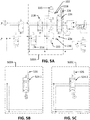
- Figs. 5A-C illustrate alternative directional and rate control configurations of a horizontal stabilizer trim actuator in accordance with an example of the disclosure.
- Fig. 5A illustrates a directional and rate control configuration 500A that includes the rate control SOV 216, the rate control spool 218, the control trim up SOV 220, the control trim down SOV 222, the directional control valve 224, the LVDT 226, the fourth hydraulic path 232, the fifth hydraulic path 234, and the pilot pressure restrictions 228 and 230.
- the configuration shown in Fig. 5A may be similar to that described in Fig. 2 .
- Fig. 5B may illustrate an alternative directional and rate control configuration 500B.
- the alternative directional and rate control configuration 500B may include an electro-hydraulic servo valve 524-1 and a LVDT 526.
- the electro-hydraulic servo valve 524-1 may be a 4-port 3-position electronically controlled valve.
- the electro-hydraulic servo valve 524-1 may be controlled by an external source such as the controller 108, input from the pilot, or from another technique.
- the LVDT 526 may monitor the position of the electro-hydraulic servo valve 524-1.
- Fig. 5C may illustrate another alternative directional and rate control configuration 500C.
- the directional and rate control configuration 500C may include a direct drive valve 524-2 and the LVDT 526.
- the direct drive valve 524-2 may be a 4-port 3-position linear or rotary direct drive valve.
- the LVDT 526 may monitor the position of the direct drive valve 524-2.
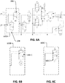
- Figs. 6A-E illustrate alternative shutoff valve configurations of a horizontal stabilizer trim actuator in accordance with an example of the disclosure.
- Fig. 6A illustrates a shutoff valve configuration 600A that includes the shutoff SOV 208 and the shutoff spool 206.
- the configuration shown in Fig. 6A may be similar to that described in Fig. 2 .
- Figs. 6B-E may illustrate alternative shutoff valve configurations 600B-E.
- the shutoff valve configuration 600B may include a motor operated 3-port 2-position shutoff valve 606-1.
- the shutoff valve configuration 600C may include a solenoid operated 3-port 2-position shutoff valve 606-2.
- the shutoff valve configuration 600D may replace the 3-port 2-position shutoff spool 206 of configuration 600A with a pilot operated 2-port 2-position shutoff valve.
- the shutoff valve configuration 600E may include a motor operated 2-port 2-position shutoff valve.
- Fig. 7 illustrates a flowchart detailing operation of a horizontal stabilizer trim actuator in accordance with an example of the disclosure.
- pressurized hydraulic fluid may flow through the inlet 202a and the filter 202b.
- instructions from the controller 108 and/or the pilot may be provided to the shutoff apparatus.
- the controller 108 and/or the pilot may, for example, provide instructions to energize the solenoid of the shutoff SOV 208.
- the instructions may be received and, if the solenoid of the shutoff SOV 208 is to be energized, the shutoff apparatus is opened and the process may proceed to block 710. If the solenoid of the shutoff SOV 208 is de-energized, the shutoff apparatus is not opened, and the process may proceed to block 708 and connect pressurized hydraulic fluid to the return port 252 and, thus, de-pressurize the hydraulic fluid.
- pressurized hydraulic fluid may flow to the directional and rate control apparatus.
- the flow rate through the rate control spool 218 may be controlled.
- the controller 108 and/or the pilot may control the flow rate through the rate control spool 218 by, for example, energizing or de-energizing the rate control SOV 216 to control the restriction of the rate control spool 218 to the flow of pressurized hydraulic fluid.
- the control trim up SOV 220 and/or the control trim down SOV 222 may receive instructions from the controller 108 and/or the pilot.
- the instructions may operate the solenoid of the control trim up SOV 220 and/or the control trim down SOV 222 and/or may operate one or both of the pilot pressure restrictions 228 and/or 230. If, from block 714, the pilot pressure from the control trim up SOV 220 and the control trim down SOV 222 are in equal block 716, the process may switch the directional control valve 224 to a blocked position (e.g., the first configuration described in Fig. 2 ) in block 718.
- a blocked position e.g., the first configuration described in Fig. 2
- the process may proceed to block 720 and switch the directional control valve 224 to a flow-through position (e.g., a position where pressurized hydraulic fluid may flow through the directional control valve 224 such as the second or third configuration described in Fig. 2 ).
- a flow-through position e.g., a position where pressurized hydraulic fluid may flow through the directional control valve 224 such as the second or third configuration described in Fig. 2 ).
- the flow of pressurized hydraulic fluid through the directional control valve 224 may power the hydraulic motor 238 in block 722. Additionally, in block 724, instructions may be received to release the hydraulic brake 242. If instructions are received for releasing the hydraulic brake 242, the hydraulic brake SOV 244 may be opened and may release the hydraulic brake 242 in block 726. The output shaft 240 may then be turned in block 728.
- the system comprises:
- the brake controller is a hydraulic brake solenoid operated valve (SOV) comprising a three port two position SOV.
- SOV hydraulic brake solenoid operated valve
- the hydraulic shutoff apparatus comprises:
- directional and rate control apparatus comprises a directional control valve and a rate apparatus comprising:
- the rate control spool is fluidically connected to the second hydraulic path and configured to allow flow of the pressurized hydraulic fluid from the second hydraulic path through the rate control spool to the directional control valve and the directional control valve is fluidically connected to the hydraulic motor.
- the directional control valve is fluidically connected to the second hydraulic path, the at least one of the directional control positions is configured to allow flow of the pressurized hydraulic fluid from the second hydraulic path through the directional control valve to the rate control spool, and the rate control spool is fluidically connected to the hydraulic motor.
- the system comprises:
- the directional control valve is a four port valve and is configured to be switched between at least three positions comprising a first position configured to prevent flow of the pressurized hydraulic fluid through the directional control valve, a second position configured to allow for the pressurized hydraulic fluid to flow through the directional control valve to the hydraulic motor in a first manner, and a third position configured to allow for the pressurized hydraulic fluid to flow through the directional control valve to the hydraulic motor in a second manner.
- the directional control valve is configured to:
- the system comprises:
- control trim up SOV is configured to be normally in the open position and the control trim down SOV is configured to be normally in the open position.
- control trim up SOV is configured to be normally in the closed position and the control trim down SOV is configured to be normally in the closed position.
- the directional and rate control apparatus is configured to be switched between the plurality of positions by an electro-hydraulic servo valve and/or a direct drive valve and the directional and rate control apparatus is fluidically connected to the second hydraulic path.
- the hydraulic shutoff apparatus comprises:
- the hydraulic shutoff apparatus comprises one of:
- the system comprises an inlet filter disposed between the hydraulic inlet and the first hydraulic path.
- the system comprises a return port fluidically connected to the directional and rate control apparatus.
- the directional and rate control apparatus further comprises a linear variable differential transformer configured to monitor the position of the directional control valve
- the system comprises:
- switching the hydraulic shutoff apparatus to a first hydraulic position comprises:
- switching the directional control valve of the directional and rate control apparatus to a first directional control position comprises:
- switching the directional control valve further comprises restricting flow of the pressurized hydraulic fluid through a trim up SOV or a trim down SOV.
- the method comprises:
- the directional control valve is switched between the plurality of positions by an electro-hydraulic servo valve and/or a direct drive valve and the directional control valve is fluidically connected to the second hydraulic path.
- the method comprises:
Landscapes
- Engineering & Computer Science (AREA)
- Physics & Mathematics (AREA)
- Fluid Mechanics (AREA)
- Aviation & Aerospace Engineering (AREA)
- Mechanical Engineering (AREA)
- General Engineering & Computer Science (AREA)
- Automation & Control Theory (AREA)
- Fluid-Pressure Circuits (AREA)
- Vehicle Body Suspensions (AREA)
Abstract
Description
- The disclosure relates generally to aircraft control surface systems and more specifically to Horizontal Stabilizer Trim Actuator (HSTA) systems used to control horizontal control surfaces.
- Aircraft often include one or more control surfaces such as, for example, one or more horizontal stabilizers. The horizontal stabilizer may be located, for example, at the rear of the aircraft and may include elevator control surfaces that are attached that may be used to change the pitch of the aircraft. A Horizontal Stabilizer Trim Actuator (HSTA) may be used to move the horizontal control surface. The HSTA may be, for example, a hydraulic system that may actuate the horizontal control surface responsive to commands issued by a controller or pilot of the aircraft.
- In certain examples, the horizontal control surface may be moved to alleviate load on the elevator control surfaces. In such examples, un-commanded or unintended movement of the horizontal stabilizer may not be desirable. As such, a HSTA designed to prevent such un-commanded or unintended movement is desirable.
- Systems and methods are disclosed herein for a hydraulic stabilizer trim actuator. In certain examples, a system may be disclosed and may include a hydraulic inlet configured to receive pressurized hydraulic fluid, a first hydraulic path fluidically connected to the hydraulic inlet, a second hydraulic path, a hydraulic shutoff apparatus fluidically connected to the first hydraulic path and the second hydraulic path and configured to be switched between a plurality of hydraulic positions wherein at least one of the hydraulic positions allows for the pressurized hydraulic fluid to flow from the first hydraulic path through the hydraulic shutoff apparatus to the second hydraulic path, a directional and rate control apparatus, a third hydraulic path fluidically connected to the directional and rate control apparatus, and a hydraulic motor fluidically connected to the directional and rate control apparatus via the third hydraulic path.
- The directional and rate control apparatus may be configured to be switched between a plurality of directional control positions where at least one of the directional control positions allows for the pressurized hydraulic fluid to flow from the second hydraulic path through the directional and rate control apparatus to the hydraulic motor. The hydraulic motor may be configured to turn an output shaft to actuate a control surface of a vehicle responsive to receiving the pressurized hydraulic fluid from the directional and rate control apparatus and configured to be locked responsive to not receiving the pressurized hydraulic fluid from the directional and rate control apparatus.
- In certain other examples, a method may be disclosed and may include receiving pressurized hydraulic fluid, flowing the pressurized hydraulic fluid into a hydraulic shutoff apparatus, switching, responsive to the flow of the pressurized hydraulic fluid into the hydraulic shutoff apparatus, the hydraulic shutoff apparatus to a first hydraulic position, flowing the pressurized hydraulic fluid into a directional and rate control apparatus, switching, responsive to the flow of the pressurized hydraulic fluid into the directional and rate control apparatus, a directional control valve of the directional and rate control apparatus to a first directional control position, monitoring the position of the directional control valve, actuating, responsive to the flow of the pressurized hydraulic fluid into the hydraulic motor, the hydraulic motor, turning an output shaft of the hydraulic motor, and actuating a control surface.
- The scope of the invention is defined by the claims, which are incorporated into this section by reference. A more complete understanding of the disclosure will be afforded to those skilled in the art, as well as a realization of additional advantages thereof, by a consideration of the following detailed description of one or more implementations. Reference will be made to the appended sheets of drawings that will first be described briefly.
-
-
Fig. 1 illustrates an example aircraft in accordance with an example of the disclosure. -
Fig. 2 illustrates an example horizontal stabilizer trim actuator in accordance with an example of the disclosure. -
Figs. 3A-B illustrate an alternative directional and rate control valve configuration of a horizontal stabilizer trim actuator in accordance with an example of the disclosure. -
Figs. 4A-B illustrate an alternative trim up solenoid operated valve and trim down solenoid operated valve configuration of a horizontal stabilizer trim actuator in accordance with an example of the disclosure. -
Figs. 5A-C illustrate alternative directional and rate control configurations of a horizontal stabilizer trim actuator in accordance with an example of the disclosure. -
Figs. 6A-E illustrate alternative shutoff valve configurations of a horizontal stabilizer trim actuator in accordance with an example of the disclosure. -
Fig. 7 illustrates a flowchart detailing operation of a horizontal stabilizer trim actuator in accordance with an example of the disclosure. - Examples of the disclosure and their advantages are best understood by referring to the detailed description that follows. It should be appreciated that like reference numerals are used to identify like elements illustrated in one or more of the figures.
- Aircraft may include control surfaces such as, for example, horizontal control surfaces located at an aft portion of the aircraft. The horizontal control surface may include one or more elevator control surfaces coupled to the horizontal control surface. The one or more elevator control surfaces may be used to, for example, change a pitch of the aircraft.
- A Horizontal Stabilizer Trim Actuator (HSTA) may be used to move the control surface (e.g., the horizontal control surface). The HSTA may, for example, change an angle of attack of the control surface or change a position of the control surface. The control surface may be moved to, for example, alleviate load on the one or more elevator control surface. In certain examples, un-commanded or unintended movement of the control surface may be undesirable. As such, a HSTA design minimizing the chance of such un-commanded or unintended movement may be desirable. Additionally, it may be desirable to keep the design of the HSTA as simple as possible to improve reliability, decrease cost, and minimize weight.
-
Fig. 1 illustrates an example aircraft in accordance with the disclosure. Theaircraft 100 ofFig. 1 may include afuselage 170,wings 172,horizontal stabilizers 174,aircraft engines 176, and avertical stabilizer 178. The wings 172s may include themovable wing components 182A-G. Themovable wing components 182A-G may be flaps, ailerons, flaperons, slats, and other movable components coupled to thewings 172. Thehorizontal stabilizers 174 may include themovable stabilizer components 184A-C. Themovable stabilizer components 184A-C may be elevator or other movable components coupled to thehorizontal stabilizers 174. - Additionally, the
aircraft 100 may include acontroller 108 and aflight deck 110. The various components of theaircraft 100 may be linked withcommunications 112 to communicate commands and conditions detected. Theaircraft 100 described inFig. 1 is exemplary and it is appreciated that in other embodiments, theaircraft 100 may include less or additional components (e.g., no horizontal stabilizer or additional stabilizers). Additionally, concepts described herein may be extended to other aircraft such as helicopters, Unmanned Aerial Vehicles, etc. - The
flight deck 110 of theaircraft 100 may include controls that may be manipulated by the pilot(s) of theaircraft 100 to provide instructions for the operation of the aircraft. For example, theflight deck 110 may include a control or controls for determining the throttle position or wing and/or horizontal stabilizer configuration of the aircraft (e.g., movement of thewings 172,horizontal stabilizers 174,movable wing components 182A-G, and/ormovable stabilizer components 184A-C). Theflight deck 110 may also include controls for determining a configuration of the horizontal stabilizer or other aerodynamic device of theaircraft 100 as well as the configuration of the vertical stabilizer. - The
flight deck 110, thewings 172, thehorizontal stabilizers 174, themovable wing components 182A-G, themovable stabilizer components 184A-C, as well as other components, may be communicatively coupled through one ormore communication channels 112. Thecommunication channel 112 may, for example, be a digital communication channel such as a wired communication circuit or a wireless communications system or an analog communication channel. Thecommunication channel 112 may link the various components to thecontroller 108. - The
controller 108 may include, for example, a single-core or multi-core processor or microprocessor, a microcontroller, a logic device, a signal processing device, memory for storing executable instructions (e.g., software, firmware, or other instructions), and/or any elements to perform any of the various operations described herein. In various examples, thecontroller 108 and/or its associated operations may be implemented as a single device or multiple devices (e.g., communicatively linked through analog, wired, or wireless connections such as the communication channel 112) to collectively constitute thecontroller 108. - The
controller 108 may include one or more memory components or devices to store data and information. The memory may include volatile and non-volatile memory. Examples of such memories include RAM (Random Access Memory), ROM (Read-Only Memory), EEPROM (Electrically-Erasable Read-Only Memory), flash memory, or other types of memory. In certain examples, thecontroller 108 may be adapted to execute instructions stored within the memory to perform various methods and processes described herein, including implementation and execution of control algorithms responsive to sensor and/or operator (e.g., flight crew) inputs. -
Fig. 2 illustrates an example horizontal stabilizer trim actuator (HSTA) in accordance with an example of the disclosure. TheHSTA 200 shown inFig. 2 includes ahydraulic shutoff apparatus 204 and a directional andrate control apparatus 214. Both thehydraulic shutoff apparatus 204 and the directional andrate control apparatus 214 may include one or more components. - The
HSTA 200 may additionally include aninlet 202A and afilter 202B, ahydraulic motor 238, anoutput shaft 240, ahydraulic brake 242, abrake controller 244, areturn check valve 246,anti-cavitation valves 248, and areturn port 252. - The
inlet 202A and thefilter 202B are fluidically connected to thehydraulic shutoff apparatus 204 via the firsthydraulic path 210. (For the purposes of this disclosure, when two components are "fluidically connected" a fluid may flow from one component to the other. There may be additional components between the two components that, in certain situations, may shut off the flow of the fluid between the two components. As long as the fluid may flow between the two components in a certain configuration, they are considered to be "fluidically connected.") As such, hydraulic fluid, which may be pressurized, may flow from theinlet 202A, through thefilter 202B, and through the firsthydraulic path 210 to thehydraulic shutoff apparatus 204. - In the example shown in
Fig. 2 , thehydraulic shutoff apparatus 204 may include theshutoff SOV 208 and theshutoff spool 206. Theshutoff SOV 208 may be a normally closed 3-port 2-position solenoid operated valve. In certain examples, the solenoid operated valve may be operated by, for example, the controller 108 (e.g., through an algorithm of the controller 108), from a pilot command, or through another operating technique. Theshutoff SOV 208 may control pilot pressure to theshutoff spool 206. Theshutoff spool 206 may be a normally closed 3-port 2-position pilot operated valve (e.g., operated by pilot pressure from, for example, the shutoff SOV 208). When theshutoff SOV 208 is energized (e.g., the solenoid is operated so that it is in the open position as opposed to the normally closed position) pilot pressure from the pressurized hydraulic fluid flowing from the firsthydraulic path 210 may energize the shutoff spool 206 (e.g., change the position of theshutoff spool 206 to an open position) such that theshutoff spool 206 allows pressurized hydraulic fluid to flow from the firsthydraulic path 210 through theshutoff spool 206 to the directional andrate control apparatus 214. Alternatively, when theshutoff SOV 208 is de-energized, the hydraulic fluid in the secondhydraulic path 212 may be routed back to thereturn port 252. - The pressurized hydraulic fluid may then flow from the
hydraulic shutoff apparatus 204 to the directional andrate control apparatus 214. In certain examples, the directional andrate control apparatus 214 may include arate control SOV 216, arate control spool 218, a control trim upSOV 220, a control trim downSOV 222, adirectional control valve 224, and a Linear Variable Differential Transformer (LVDT) 226. Other examples of the directional andrate control apparatus 214 may include additional, fewer, and/or different components. - The
rate control SOV 216 may be a normally closed 3-port 2-position solenoid operated valve. Therate control SOV 216 may control pilot pressure to therate control spool 218. Therate control spool 218 may be a normally open 4-port 2-position pilot operated valve operated via pilot pressure from therate control SOV 216. When theshutoff spool 206 is energized, pressurized hydraulic fluid may flow into secondhydraulic path 212. From the secondhydraulic path 212, the pressurized hydraulic fluid may flow to therate control SOV 216. When therate control spool 216 is energized (e.g., switched from the closed position to an open position), pilot pressure from therate control SOV 216 may accordingly energize therate control spool 218. - Pressurized hydraulic fluid from the second
hydraulic path 212 may flow through therate control spool 218. In a normal configuration (e.g., when therate control spool 218 is not energized), therate control spool 218 may be in a low flow resistance configuration (e.g., a high flow rate configuration). When therate control spool 218 is energized, therate control spool 218 may be in a high flow resistance configuration (e.g., a low flow rate configuration) and provide additional resistance to the flow of pressurized hydraulic fluid through therate control spool 218. As such, operation of therate control SOV 216 may control the resistance of therate control spool 218 to flow of the hydraulic fluid. In certain examples, therate control spool 218 may include two paths for pressurized hydraulic fluid to flow through. - Pressurized hydraulic fluid from the
rate control spool 218 may flow to thedirectional control valve 224. Thedirectional control valve 224 may be a 4-port 3-position control valve that is spring-centered and pressure-centered. Thedirectional control valve 224 may be pressure-centered via pilot pressure from the control trim upSOV 220 and the control trim downSOV 222. Pilot pressure from the control trim upSOV 220 may reach thedirectional control valve 224 via a fourthhydraulic path 232 and pilot pressure from the control trim downSOV 222 may reach thedirectional control valve 224 via a fifthhydraulic path 234. In examples where therate control spool 218 includes two paths for pressurized hydraulic fluid to flow through, thedirectional control valve 224 may also receive the pressurized hydraulic fluid via two paths. - The control trim up
SOV 220 and the control trim downSOV 222 may both be normally open 3-port 2-position solenoid operated valves. The control trim upSOV 220 and/or the control trim downSOV 222 may control pilot pressure from the respective control trim up/down SOV to thedirectional control valve 224. Energizing the control trim upSOV 220 and/or the control trim downSOV 222 may change the configuration of the respective SOV to a closed position. In the closed position, pilot pressure may not be present to thedirection control valve 224. Additionally,pilot pressure restrictions hydraulic path 232 and the fifthhydraulic path 234. Thepilot pressure restrictions hydraulic path 232 and the fifthhydraulic path 234 as an alternative technique of controlling the configuration of thedirectional control valve 224. For example, the configuration of thedirectional control valve 224 may be controlled by restricting none, one, or both of the flow of pressurized hydraulic fluid through the fourthhydraulic path 232 and/or the fifthhydraulic path 234. Thepilot pressure restrictions controller 108, by the pilot, fixed through mechanical means, or through another technique. - Referring back to the
directional control valve 224, the currentdirectional control valve 224 may include 3 positions. When pilot pressure from both or neither of the control trim up 220 and the control trim down 222 are present, thedirectional control valve 224 may be in a first configuration that prevents flow through both of the paths that the pressurized hydraulic fluid flows through to the thirdhydraulic path 236. In certain examples, the first configuration may be a centered position of thedirectional control valve 224. When pilot pressure from only one of the control trim upSOV 220 and the control trim downSOV 222 is present, thedirectional control valve 224 may be in a second configuration that allows flow of the pressurized hydraulic fluid linearly through thedirectional control valve 224 or may be in a third configuration that crosses the flow of the hydraulic fluid through thedirectional control valve 224. - For example, the
directional control valve 224 may include first and second inlets and first and second outlets. In the first configuration, no or minimal flow may be allowed through thedirectional control valve 224. In the second configuration, hydraulic fluid entering the first inlet may flow through to the first outlet and hydraulic fluid entering the second inlet may flow through to the second outlet. In the third configuration, hydraulic fluid entering the first inlet may flow through to the second outlet and hydraulic fluid entering the second inlet may flow through to the first outlet. - In certain examples, the position of the
directional control valve 224 may be monitored by the Linear Variable Displacement Transformer (LVDT) 226. TheLVDT 226 may determine and output data directed to the position of thedirectional control valve 224 to thecontroller 108. Thecontroller 108 may then confirm, from theLVDT 226 output, that the position of thedirectional control valve 224 is consistent with that commanded (e.g., via commands given to the solenoids of the control trim upSOV 220 and/or the control trim down SOV 222). Certain other examples may not include theLVDT 226. In such examples, the position of thedirectional control valve 226 may be determined from the commands issued by thecontroller 108. - Pressurized hydraulic fluid exiting the
directional control valve 224 may flow into a thirdhydraulic path 236. The thirdhydraulic path 236 may, for example, be fluidically connected to thehydraulic motor 238. Thehydraulic motor 238 may be powered by the pressurized hydraulic fluid flowing from thedirectional control valve 224 into, for example, motor control ports of thehydraulic motor 238. In certain examples, thehydraulic motor 238 may be a fixed displacement bi-directional motor that turns theoutput shaft 240. As such, when thedirectional control valve 224 is in the first configuration, no or minimal pressurized hydraulic fluid may reach thehydraulic motor 238 and thehydraulic motor 238 may be locked (e.g., may not be turning). When thedirectional control valve 224 is in the second configuration, thehydraulic motor 238 may turn in a first direction and when thedirectional control valve 224 is in the third configuration, thehydraulic motor 238 may turn in a second direction. - The
output shaft 240 may, in certain examples, be connected to a HSTA gearbox. The HSTA gearbox may control the displacement and/or rate of change of thehorizontal stabilizers 174. The gearbox may be controlled by thecontroller 108, may be pilot controlled, may be controller through mechanical means, may be a fixed gear ratio, or may be controlled through another technique. In certain examples, there may be multiplehydraulic motors 238 and/ormultiple output shafts 240. In such examples, a speed-summing differential may be included to combine the rotation of the multiplehydraulic motors 238 and/or themultiple output shafts 240. - In certain examples, the
anti-cavitation valves 248 may allow hydraulic fluid to enter the motor control ports if pressure within the thirdhydraulic path 236 drops below a return pressure (e.g., a pressure of the return line 250). - The
hydraulic brake 242 may be a power-off brake (e.g., when pressurized hydraulic fluid is not flowing into a port of thehydraulic brake 242, the brake may be set and may restrict rotation of the output shaft 240). In certain examples, thebrake controller 244 may be a hydraulic brake solenoid operated valve (SOV) though other examples may include other types of brake controllers, such as electronic controllers or other types of valves. Thebrake controller 244 may control pressure to thehydraulic brake 242. Thebrake controller 244 may be a normally closed 3-port 2-position solenoid operated valve. When thebrake controller 244 is energized, pressurized hydraulic fluid may flow to thehydraulic brake 242 and release thehydraulic brake 242. In certain examples, the pressurized hydraulic fluid may release thehydraulic brake 242 by overcoming a spring force holding thehydraulic brake 242 in a position restricting rotation of theoutput shaft 240. When thehydraulic brake 242 is released, thehydraulic brake 242 may no longer or may minimally restrict movement of theoutput shaft 240. In certain examples, thebrake controller 244 and thehydraulic brake 242 may be replaced by an electric power-off brake. In such examples, the electric power-off brake may restrict movement of theoutput shaft 240 when engaged (e.g., when an instruction is provided to the electric power-off brake from the controller 108). - In certain examples, a pressure switch and/or pressure transducer may be included between the
brake controller 244 and thehydraulic brake 242. Additionally or alternatively, a LVDT may be coupled to the hydraulic brake 242 (e.g., the brake piston of the hydraulic brake 242). Such an LVDT may provide information as to whether thehydraulic brake 242 is engaged. - Additionally, a
return check valve 246 may be on thereturn line 250. Thereturn check valve 246 may prevent system and return pressure transients from reaching the hydraulic brake 242 (e.g., may prevent momentary pressures from disengaging the hydraulic brake 242). In certain other examples, thereturn line 250 may include a hydraulic accumulator alternative or in addition to thereturn check valve 246. The hydraulic accumulator may prevent cavitation of the hydraulic fluid within the hydraulic motor. - Various hydraulic paths of the
HSTA 200 may be fluidically connected to thereturn port 252. Thereturn port 252 may be connected to a source of pressurized hydraulic fluid. In certain examples, thereturn port 252 may be fluidically connected to the same source of pressurized hydraulic fluid that provides fluid to the inlet 202. Thereturn port 252 may receive excess hydraulic fluid pressure of theHSTA 200. - The
HSTA 200 may provide for three independent techniques for shutdown when an un-commanded or unintended movement event is detected. For example, theshutoff SOV 208 may be de-energized (e.g., by thecontroller 108, the pilot, or another input). De-energizing theshutoff SOV 208 may block inlet pressure from the inlet 202 from reaching the rest of theHSTA 200 and may connect the secondhydraulic path 212 to thereturn port 252. Additionally, the control trim upSOV 220 and the control trim downSOV 222 may also be de-energized. De-energizing the control trim upSOV 220 and the control trim downSOV 222 may cause thedirectional control valve 224 to transition to the first configuration and lock thehydraulic motor 238 in place. Also, thebrake controller 244 may be de-energized and cause thehydraulic brake 242 to engage to restrain movement of theoutput shaft 240. Restraining the movement of theoutput shaft 240 may prevent movement of any movable control surfaces (e.g.,movable wing components 182A-G,movable stabilizer components 184A-C, and/or horizontal stabilizers 174) coupled to theHSTA 200. -
Figs. 3A-B illustrate an alternative directional and rate control valve configuration of a horizontal stabilizer trim actuator in accordance with an example of the disclosure.Fig. 3A illustrates a directional and ratecontrol component configuration 300A that includes therate control spool 218, the control trim upSOV 220, the control trim downSOV 222, thedirectional control valve 224, theLVDT 226, the fourthhydraulic path 232, the fifthhydraulic path 234, and thepilot pressure restrictions Fig. 3A may be similar to that described inFig. 2 . -
Fig. 3B may illustrate an alternative directional and ratecontrol component configuration 300B. The alternative directional and ratecontrol component configuration 300B, may include arate control spool 318, a control trim upSOV 320, a control trim downSOV 322, a directional control valve 324, aLVDT 326, fourthhydraulic path 332, fifthhydraulic path 334, andpilot pressure restrictions - The alternative directional and rate
control component configuration 300B may be similar to the directional and ratecontrol component configuration 300A. However, in the alternative directional and ratecontrol component configuration 300B, pressurized hydraulic fluid from the second hydraulic path (not shown inFig. 3B , but shown inFig. 2 ) may flow to the directional control valve 324. Therate control spool 318 may receive pressurized hydraulic fluid from the directional control valve 324. Pressurized hydraulic fluid may then flow from therate control spool 318 to the third hydraulic path 236 (not shown inFig. 3B , but shown inFig. 2 ). -
Figs. 4A-B illustrate an alternative trim up solenoid operated valve and trim down solenoid operated valve configuration of a horizontal stabilizer trim actuator in accordance with an example of the disclosure.Fig. 4A illustrates a control trim up and trim downconfiguration 400A that includes the control trim upSOV 220 and the control trim downSOV 222. The configuration shown inFig. 4A may be similar to that described inFig. 2 . -
Fig. 4B illustrates an alternative control trim up and trim downconfiguration 400B. The alternative control trim up and trim downconfiguration 400B includes a control trim upSOV 420 and a control trim downSOV 422. The control trim upSOV 420 and the control trim downSOV 422 may be normally closed SOVs. As such, when the control trim upSOV 420 and the control trim downSOV 422 are un-commanded, the fourthhydraulic path 232 and the fifthhydraulic path 234 are fluidically connected to thereturn line 250. The directional control valve (not shown inFig. 4B , but shown inFig. 2 ) may be spring-centered to its first configuration. When one of the control trim upSOV 420 or the control trim downSOV 422 is energized, pilot pressure may be ported to thedirectional control valve 224. Such pressure may change the position of thedirection control valve 224 to a flow-through position. -
Figs. 5A-C illustrate alternative directional and rate control configurations of a horizontal stabilizer trim actuator in accordance with an example of the disclosure.Fig. 5A illustrates a directional andrate control configuration 500A that includes therate control SOV 216, therate control spool 218, the control trim upSOV 220, the control trim downSOV 222, thedirectional control valve 224, theLVDT 226, the fourthhydraulic path 232, the fifthhydraulic path 234, and thepilot pressure restrictions Fig. 5A may be similar to that described inFig. 2 . -
Fig. 5B may illustrate an alternative directional andrate control configuration 500B. The alternative directional andrate control configuration 500B may include an electro-hydraulic servo valve 524-1 and aLVDT 526. The electro-hydraulic servo valve 524-1 may be a 4-port 3-position electronically controlled valve. The electro-hydraulic servo valve 524-1 may be controlled by an external source such as thecontroller 108, input from the pilot, or from another technique. TheLVDT 526 may monitor the position of the electro-hydraulic servo valve 524-1. -
Fig. 5C may illustrate another alternative directional andrate control configuration 500C. The directional andrate control configuration 500C may include a direct drive valve 524-2 and theLVDT 526. The direct drive valve 524-2 may be a 4-port 3-position linear or rotary direct drive valve. TheLVDT 526 may monitor the position of the direct drive valve 524-2. -
Figs. 6A-E illustrate alternative shutoff valve configurations of a horizontal stabilizer trim actuator in accordance with an example of the disclosure.Fig. 6A illustrates ashutoff valve configuration 600A that includes theshutoff SOV 208 and theshutoff spool 206. The configuration shown inFig. 6A may be similar to that described inFig. 2 . -
Figs. 6B-E may illustrate alternativeshutoff valve configurations 600B-E. Theshutoff valve configuration 600B may include a motor operated 3-port 2-position shutoff valve 606-1. Theshutoff valve configuration 600C may include a solenoid operated 3-port 2-position shutoff valve 606-2. Theshutoff valve configuration 600D may replace the 3-port 2-position shutoff spool 206 ofconfiguration 600A with a pilot operated 2-port 2-position shutoff valve. Theshutoff valve configuration 600E may include a motor operated 2-port 2-position shutoff valve. -
Fig. 7 illustrates a flowchart detailing operation of a horizontal stabilizer trim actuator in accordance with an example of the disclosure. Inblock 702, pressurized hydraulic fluid may flow through the inlet 202a and the filter 202b. Inblock 704, instructions from thecontroller 108 and/or the pilot may be provided to the shutoff apparatus. Thecontroller 108 and/or the pilot may, for example, provide instructions to energize the solenoid of theshutoff SOV 208. Inblock 706, the instructions may be received and, if the solenoid of theshutoff SOV 208 is to be energized, the shutoff apparatus is opened and the process may proceed to block 710. If the solenoid of theshutoff SOV 208 is de-energized, the shutoff apparatus is not opened, and the process may proceed to block 708 and connect pressurized hydraulic fluid to thereturn port 252 and, thus, de-pressurize the hydraulic fluid. - In
block 710, pressurized hydraulic fluid may flow to the directional and rate control apparatus. Inblock 712, the flow rate through therate control spool 218 may be controlled. Thecontroller 108 and/or the pilot may control the flow rate through therate control spool 218 by, for example, energizing or de-energizing therate control SOV 216 to control the restriction of therate control spool 218 to the flow of pressurized hydraulic fluid. - In
block 714, the control trim upSOV 220 and/or the control trim downSOV 222 may receive instructions from thecontroller 108 and/or the pilot. The instructions may operate the solenoid of the control trim upSOV 220 and/or the control trim downSOV 222 and/or may operate one or both of thepilot pressure restrictions 228 and/or 230. If, fromblock 714, the pilot pressure from the control trim upSOV 220 and the control trim downSOV 222 are inequal block 716, the process may switch thedirectional control valve 224 to a blocked position (e.g., the first configuration described inFig. 2 ) inblock 718. Otherwise, the process may proceed to block 720 and switch thedirectional control valve 224 to a flow-through position (e.g., a position where pressurized hydraulic fluid may flow through thedirectional control valve 224 such as the second or third configuration described inFig. 2 ). - The flow of pressurized hydraulic fluid through the
directional control valve 224 may power thehydraulic motor 238 inblock 722. Additionally, inblock 724, instructions may be received to release thehydraulic brake 242. If instructions are received for releasing thehydraulic brake 242, thehydraulic brake SOV 244 may be opened and may release thehydraulic brake 242 inblock 726. Theoutput shaft 240 may then be turned inblock 728. - According to a first aspect of the disclosure, there is provided:
- A system comprising:
- a hydraulic inlet configured to receive pressurized hydraulic fluid;
- a first hydraulic path fluidically connected to the hydraulic inlet;
- a second hydraulic path;
- a hydraulic shutoff apparatus fluidically connected to the first hydraulic path and the second hydraulic path and configured to be switched between a plurality of hydraulic positions wherein at least one of the hydraulic positions allows for the pressurized hydraulic fluid to flow from the first hydraulic path through the hydraulic shutoff apparatus to the second hydraulic path;
- a directional and rate control apparatus;
- a third hydraulic path fluidically connected to the directional and rate control apparatus; and
- a hydraulic motor fluidically connected to the directional and rate control apparatus via the third hydraulic path, wherein:
- the directional and rate control apparatus is configured to be switched between a plurality of directional control positions wherein at least one of the directional control positions allows for the pressurized hydraulic fluid to flow from the second hydraulic path through the directional and rate control apparatus to the hydraulic motor, and
- the hydraulic motor is configured to turn an output shaft to actuate a control surface of a vehicle responsive to receiving the pressurized hydraulic fluid from the directional and rate control apparatus and configured to be locked responsive to not receiving the pressurized hydraulic fluid from the directional and rate control apparatus.
- Optionally, the system comprises:
- a brake controller fluidically connected to the hydraulic shutoff apparatus via the second hydraulic path, wherein the brake controller is configured to allow flow of the pressurized hydraulic fluid in an open position and configured to prevent flow of the pressurized hydraulic fluid in a closed position; and
- a hydraulic brake configured to restrict movement of the hydraulic motor and/or the output shaft responsive to not receiving the pressurized hydraulic fluid from the brake controller.
- Optionally, the brake controller is a hydraulic brake solenoid operated valve (SOV) comprising a three port two position SOV.
- Optionally, the hydraulic shutoff apparatus comprises:
- a shutoff SOV fluidically connected to the first hydraulic path, wherein the shutoff SOV is a three port two position SOV configured to allow flow of the pressurized hydraulic fluid in an open position and configured to prevent flow of the pressurized hydraulic fluid in a closed position; and
- a shutoff spool fluidically connected to the first hydraulic path, wherein the shutoff spool is a three port two position pilot operated valve configured to, responsive to the shutoff SOV allowing flow of the pressurized hydraulic fluid, allow flow of the pressurized hydraulic fluid from the first hydraulic path to the directional and rate control apparatus.
- Optionally, directional and rate control apparatus comprises a directional control valve and a rate apparatus comprising:
- a rate control SOV fluidically connected to the second hydraulic path, wherein the rate control SOV is a three port two position SOV configured to allow flow of the pressurized hydraulic fluid to a rate control spool in an open position and configured to prevent flow of the pressurized hydraulic fluid in a closed position; and
- the rate control spool, wherein the rate control spool is a four port two position pilot operated valve configured to, responsive to the rate control SOV allowing flow of the pressurized hydraulic fluid, further restrict flow of hydraulic fluid through the rate control spool.
- Optionally, the rate control spool is fluidically connected to the second hydraulic path and configured to allow flow of the pressurized hydraulic fluid from the second hydraulic path through the rate control spool to the directional control valve and the directional control valve is fluidically connected to the hydraulic motor.
- Optionally, the directional control valve is fluidically connected to the second hydraulic path, the at least one of the directional control positions is configured to allow flow of the pressurized hydraulic fluid from the second hydraulic path through the directional control valve to the rate control spool, and the rate control spool is fluidically connected to the hydraulic motor.
- Optionally, the system comprises:
- a fourth hydraulic path;
- a fifth hydraulic path, wherein the directional and rate control apparatus comprises a directional control valve and a pressure centered apparatus fluidically connected to the fourth hydraulic path and the fifth hydraulic path and configured to switch between the plurality of directional control positions responsive to the flow of the pressurized hydraulic fluid from the fourth hydraulic path and the fifth hydraulic path;
- a control trim up SOV fluidically connected to the second hydraulic path and the fourth hydraulic path, wherein the control trim up SOV is a three port two position SOV configured to allow flow of the pressurized hydraulic fluid to the fourth hydraulic path in an open position and configured to prevent flow of the pressurized hydraulic fluid in a closed position; and
- a control trim down SOV fluidically connected to the second hydraulic path and the fifth hydraulic path, wherein the control trim down SOV is a three port two position SOV configured to allow flow of the pressurized hydraulic fluid to the fifth hydraulic path in an open position and configured to prevent flow of the pressurized hydraulic fluid in a closed position.
- Optionally, the directional control valve is a four port valve and is configured to be switched between at least three positions comprising a first position configured to prevent flow of the pressurized hydraulic fluid through the directional control valve, a second position configured to allow for the pressurized hydraulic fluid to flow through the directional control valve to the hydraulic motor in a first manner, and a third position configured to allow for the pressurized hydraulic fluid to flow through the directional control valve to the hydraulic motor in a second manner.
- Optionally, the directional control valve is configured to:
- be in the first position responsive to substantially equal hydraulic pressure within the fourth hydraulic path and the fifth hydraulic path;
- be in the second position responsive to hydraulic pressure that is substantially greater within the fourth hydraulic path than within the fifth hydraulic path; and
- be in the third position responsive to hydraulic pressure that is substantially greater within the fifth hydraulic path than within the fourth hydraulic path.
- Optionally, the system comprises:
- a first pilot operated restriction coupled to the fourth hydraulic path and configured to restrict flow of the pressurized hydraulic fluid through the fourth hydraulic path; and
- a second pilot operated restriction coupled to the fifth hydraulic path and configured to restrict flow of the pressurized hydraulic fluid through the fifth hydraulic path.
- Optionally, the control trim up SOV is configured to be normally in the open position and the control trim down SOV is configured to be normally in the open position.
- Optionally, the control trim up SOV is configured to be normally in the closed position and the control trim down SOV is configured to be normally in the closed position.
- Optionally, the directional and rate control apparatus is configured to be switched between the plurality of positions by an electro-hydraulic servo valve and/or a direct drive valve and the directional and rate control apparatus is fluidically connected to the second hydraulic path.
- Optionally, the hydraulic shutoff apparatus comprises:
- a shutoff SOV fluidically connected to the first hydraulic path, wherein the shutoff SOV is a three port two position SOV configured to allow flow of the pressurized hydraulic fluid in an open position and configured to prevent flow of the pressurized hydraulic fluid in a closed position; and
- a shutoff spool fluidically connected to the first hydraulic path, wherein the shutoff spool is a two port two position pilot operated valve configured to, responsive to the shutoff SOV allowing flow of the pressurized hydraulic fluid, allow flow of the pressurized hydraulic fluid from the first hydraulic path to the directional and rate control apparatus.
- Optionally, the hydraulic shutoff apparatus comprises one of:
- a shutoff valve fluidically connected to the first hydraulic path, wherein the shutoff valve is a three port two position motor operated valve configured to allow flow of the pressurized hydraulic fluid in an open position and configured to prevent flow of the pressurized hydraulic fluid in a closed position;
- a shutoff valve fluidically connected to the first hydraulic path, wherein the shutoff valve is a two port two position motor operated valve configured to allow flow of the pressurized hydraulic fluid in an open position and configured to prevent flow of the pressurized hydraulic fluid in a closed position; or
- a shutoff valve fluidically connected to the first hydraulic path, wherein the shutoff valve is a two port two position solenoid operated valve configured to allow flow of the pressurized hydraulic fluid in an open position and configured to prevent flow of the pressurized hydraulic fluid in a closed position.
- Optionally, the system comprises an inlet filter disposed between the hydraulic inlet and the first hydraulic path.
- Optionally, the system comprises a return port fluidically connected to the directional and rate control apparatus.
- Optionally, the directional and rate control apparatus further comprises a linear variable differential transformer configured to monitor the position of the directional control valve
- Optionally, the system comprises:
- an electric brake configured to restrict movement of the hydraulic motor and/or the output shaft responsive receiving an engagement instruction.
- According to a second aspect of the disclosure, there is provided:
- An aircraft comprising the apparatus of the first aspect with or without any optional feature thereof, wherein the vehicle is the aircraft and the aircraft comprises:
- a fuselage; and
- the control surface coupled to the fuselage.
- According to a third aspect of the disclosure, there is provided:
- A method comprising:
- receiving pressurized hydraulic fluid;
- flowing the pressurized hydraulic fluid into a hydraulic shutoff apparatus;
- switching, responsive to the flow of the pressurized hydraulic fluid into the hydraulic shutoff apparatus, the hydraulic shutoff apparatus to a first hydraulic position;
- flowing the pressurized hydraulic fluid into a directional and rate control apparatus;
- switching, responsive to the flow of the pressurized hydraulic fluid into the directional and rate control apparatus, a directional control valve of the directional and rate control apparatus to a first directional control position;
- monitoring the position of the directional control valve;
- actuating, responsive to the flow of the pressurized hydraulic fluid into the hydraulic motor, the hydraulic motor;
- turning an output shaft of the hydraulic motor; and actuating a control surface.
- Optionally, switching the hydraulic shutoff apparatus to a first hydraulic position comprises:
- switching a shutoff solenoid operated valve (SOV) to an open position to allow flow of the pressurized hydraulic fluid to a shutoff spool; and
- switching the shutoff spool, responsive to the flow of the pressurized hydraulic fluid to the shutoff spool, to flow the pressurized hydraulic fluid into the directional and rate control apparatus and a brake controller.
- Optionally, switching the directional control valve of the directional and rate control apparatus to a first directional control position comprises:
- flowing pressurized hydraulic fluid through at least one of a fourth hydraulic path via a control trim up SOV and/or a fifth hydraulic path via a control trim down SOV such that hydraulic pressure through the fourth hydraulic path and the fifth hydraulic path are substantially different; and
- switching the directional control valve to a flow-through configuration responsive to the substantially different hydraulic pressure in the fourth hydraulic path and the fifth hydraulic path to flow the pressurized hydraulic fluid to the hydraulic motor.
- Optionally, switching the directional control valve further comprises restricting flow of the pressurized hydraulic fluid through a trim up SOV or a trim down SOV.
- Optionally, the method comprises:
- switching a rate control SOV to an open position to allow flow of the pressurized hydraulic fluid to a rate control spool; and
- restricting flow of hydraulic fluid through the rate control spool responsive to the rate control SOV allowing flow of the pressurized hydraulic fluid to the rate control spool.
- Optionally, the directional control valve is switched between the plurality of positions by an electro-hydraulic servo valve and/or a direct drive valve and the directional control valve is fluidically connected to the second hydraulic path.
- Optionally, the method comprises:
- switching a brake controller to an open position to allow flow of the pressurized hydraulic fluid to a hydraulic brake; and
- releasing the hydraulic brake configured responsive to the flow of the pressurized hydraulic fluid from the brake controller to the hydraulic brake.
- Examples described above illustrate but do not limit the invention. It should also be understood that numerous modifications and variations are possible in accordance with the principles of the present invention. Accordingly, the scope of the invention is defined only by the following claims.
Claims (15)
- A system comprising:a hydraulic inlet (202A) configured to receive pressurized hydraulic fluid;a first hydraulic path (210) fluidically connected to the hydraulic inlet;a second hydraulic path (212);a hydraulic shutoff apparatus (204) fluidically connected to the first hydraulic path (210) and the second hydraulic path (212) and configured to be switched between a plurality of hydraulic positions wherein at least one of the hydraulic positions allows for the pressurized hydraulic fluid to flow from the first hydraulic path (210) through the hydraulic shutoff apparatus (204) to the second hydraulic path (212);a directional and rate control apparatus (214);a third hydraulic path (236) fluidically connected to the directional and rate control apparatus (214); anda hydraulic motor (238) fluidically connected to the directional and rate control apparatus (214) via the third hydraulic path (236), wherein:the directional and rate control apparatus (214) is configured to be switched between a plurality of directional control positions wherein at least one of the directional control positions allows for the pressurized hydraulic fluid to flow from the second hydraulic path (212) through the directional and rate control apparatus (214) to the hydraulic motor (238), andthe hydraulic motor (238) is configured to turn an output shaft (240) to actuate a control surface of a vehicle responsive to receiving the pressurized hydraulic fluid from the directional and rate control apparatus (214) and configured to be locked responsive to not receiving the pressurized hydraulic fluid from the directional and rate control apparatus (214).
- The system of claim 1, further comprising:a brake controller (244) fluidically connected to the hydraulic shutoff apparatus (204) via the second hydraulic path (212), wherein the brake controller (244) is configured to allow flow of the pressurized hydraulic fluid in an open position and configured to prevent flow of the pressurized hydraulic fluid in a closed position; anda hydraulic brake (242) configured to restrict movement of the hydraulic motor (238) and/or the output shaft (240) responsive to not receiving the pressurized hydraulic fluid from the brake controller (244).
- The system of claims 1 or 2, wherein the hydraulic shutoff apparatus (204) comprises:a shutoff SOV (208) fluidically connected to the first hydraulic path (210), wherein the shutoff SOV (208) is a three port two position SOV configured to allow flow of the pressurized hydraulic fluid in an open position and configured to prevent flow of the pressurized hydraulic fluid in a closed position; anda shutoff spool (206) fluidically connected to the first hydraulic path (210), wherein the shutoff spool (206) is a three port two position pilot operated valve configured to, responsive to the shutoff SOV (208) allowing flow of the pressurized hydraulic fluid, allow flow of the pressurized hydraulic fluid from the first hydraulic path (210) to the directional and rate control apparatus (214).
- The system of any one of claims 1 to 3, wherein directional and rate control apparatus (214) comprises a directional control valve and a rate apparatus comprising:a rate control SOV (216) fluidically connected to the second hydraulic path (212), wherein the rate control SOV (216) is a three port two position SOV configured to allow flow of the pressurized hydraulic fluid to a rate control spool (218) in an open position and configured to prevent flow of the pressurized hydraulic fluid in a closed position; andthe rate control spool (218), wherein the rate control spool (218) is a four port two position pilot operated valve configured to, responsive to the rate control SOV (216) allowing flow of the pressurized hydraulic fluid, further restrict flow of hydraulic fluid through the rate control spool (218).
- The system of any one of claims 1 to 4, wherein the rate control spool (218) is fluidically connected to the second hydraulic path (212) and configured to allow flow of the pressurized hydraulic fluid from the second hydraulic path (212) through the rate control spool(218) to the directional control valve (224) and the directional control valve (224) is fluidically connected to the hydraulic motor (238).
- The system of any one of claims 1 to 5, wherein the directional control valve (224) is fluidically connected to the second hydraulic path (212), the at least one of the directional control positions is configured to allow flow of the pressurized hydraulic fluid from the second hydraulic path (212) through the directional control valve (224) to the rate control spool (218), and the rate control spool (218) is fluidically connected to the hydraulic motor (238).
- The system of any one of claims 1 to 6, further comprising:a fourth hydraulic path (232);a fifth hydraulic path (234), wherein the directional and rate control apparatus (214) comprises a directional control valve (224) and a pressure centered apparatus fluidically connected to the fourth hydraulic path (232) and the fifth hydraulic path (234) and configured to switch between the plurality of directional control positions responsive to the flow of the pressurized hydraulic fluid from the fourth hydraulic path (232)and the fifth hydraulic path (234);a control trim up SOV (220) fluidically connected to the second hydraulic path (212) and the fourth hydraulic path (232), wherein the control trim up SOV (220) is a three port two position SOV configured to allow flow of the pressurized hydraulic fluid to the fourth hydraulic path (232) in an open position and configured to prevent flow of the pressurized hydraulic fluid in a closed position; anda control trim down SOV (222) fluidically connected to the second hydraulic path (212) and the fifth hydraulic path (234), wherein the control trim down SOV (222) is a three port two position SOV configured to allow flow of the pressurized hydraulic fluid to the fifth hydraulic path (234) in an open position and configured to prevent flow of the pressurized hydraulic fluid in a closed position.
- The system of claim 7, wherein the directional control valve (224) is a four port valve and is configured to be switched between at least three positions comprising a first position configured to prevent flow of the pressurized hydraulic fluid through the directional control valve (224), a second position configured to allow for the pressurized hydraulic fluid to flow through the directional control valve (224) to the hydraulic motor (238) in a first manner, and a third position configured to allow for the pressurized hydraulic fluid to flow through the directional control valve (224) to the hydraulic motor (238) in a second manner.
- The system of claim 8, wherein the directional control valve (224) is configured to:be in the first position responsive to substantially equal hydraulic pressure within the fourth hydraulic path (232) and the fifth hydraulic path (234);be in the second position responsive to hydraulic pressure that is substantially greater within the fourth hydraulic path (232) than within the fifth hydraulic path (234); andbe in the third position responsive to hydraulic pressure that is substantially greater within the fifth hydraulic path (234) than within the fourth hydraulic path (232).
- The system of any one of claims 7 to 9, further comprising:a first pilot operated restriction coupled to the fourth hydraulic path (232) and configured to restrict flow of the pressurized hydraulic fluid through the fourth hydraulic path (232); anda second pilot operated restriction coupled to the fifth hydraulic path (234) and configured to restrict flow of the pressurized hydraulic fluid through the fifth hydraulic path (234).
- The system of any one of claims 7 to 10, wherein the control trim up SOV (220) is configured to be normally in the open position and the control trim down SOV (222) is configured to be normally in the open position; or, wherein the control trim up SOV (220) is configured to be normally in the closed position and the control trim down SOV (222) is configured to be normally in the closed position.
- The system of any one of claims 1 to 11, wherein the directional and rate control apparatus (214) is configured to be switched between the plurality of positions by an electro-hydraulic servo valve (524-1) and/or a direct drive valve (524-2) and the directional and rate control apparatus (214) is fluidically connected to the second hydraulic path (212).
- The system of claims 1 to 12, wherein the hydraulic shutoff apparatus (204) comprises:a shutoff SOV (208) fluidically connected to the first hydraulic path (210), wherein the shutoff SOV (208) is a three port two position SOV configured to allow flow of the pressurized hydraulic fluid in an open position and configured to prevent flow of the pressurized hydraulic fluid in a closed position; anda shutoff spool (206) fluidically connected to the first hydraulic path (210), wherein the shutoff spool (206) is a two port two position pilot operated valve configured to, responsive to the shutoff SOV (208) allowing flow of the pressurized hydraulic fluid, allow flow of the pressurized hydraulic fluid from the first hydraulic path (210) to the directional and rate control apparatus (214).
- The system of any one of claims 1 to 13, wherein the directional and rate control apparatus (214) further comprises a linear variable differential transformer (226) configured to monitor the position of the directional control valve (224).
- An aircraft (100) comprising the apparatus of any one of claims 1-14, wherein the vehicle is the aircraft and the aircraft comprises:a fuselage (170); andthe control surface coupled to the fuselage.
Applications Claiming Priority (1)
| Application Number | Priority Date | Filing Date | Title |
|---|---|---|---|
| US15/214,366 US10450056B2 (en) | 2016-07-19 | 2016-07-19 | Horizontal stabilizer trim actuator systems and methods |
Publications (2)
| Publication Number | Publication Date |
|---|---|
| EP3272650A1 true EP3272650A1 (en) | 2018-01-24 |
| EP3272650B1 EP3272650B1 (en) | 2019-05-29 |
Family
ID=59315438
Family Applications (1)
| Application Number | Title | Priority Date | Filing Date |
|---|---|---|---|
| EP17180456.0A Active EP3272650B1 (en) | 2016-07-19 | 2017-07-10 | Horizontal stabilizer trim actuator systems and methods |
Country Status (4)
| Country | Link |
|---|---|
| US (2) | US10450056B2 (en) |
| EP (1) | EP3272650B1 (en) |
| CN (1) | CN107628233B (en) |
| CA (1) | CA2966465C (en) |
Cited By (1)
| Publication number | Priority date | Publication date | Assignee | Title |
|---|---|---|---|---|
| EP3549859A1 (en) * | 2018-04-06 | 2019-10-09 | Goodrich Actuation Systems Limited | Hydraulic power drive unit |
Families Citing this family (5)
| Publication number | Priority date | Publication date | Assignee | Title |
|---|---|---|---|---|
| US10829210B2 (en) | 2018-06-27 | 2020-11-10 | The Boeing Company | Braking system for a dual landing gear aircraft |
| EP3623643A1 (en) * | 2018-09-14 | 2020-03-18 | Ratier-Figeac SAS | Actuator |
| WO2022192698A1 (en) | 2021-03-12 | 2022-09-15 | Essex Industries, Inc., | Rocker switch |
| US11688568B2 (en) | 2021-03-15 | 2023-06-27 | Essex Industries, Inc. | Five-position switch |
| US20250044816A1 (en) * | 2023-07-31 | 2025-02-06 | Hamilton Sundstrand Corporation | Valve systems |
Citations (5)
| Publication number | Priority date | Publication date | Assignee | Title |
|---|---|---|---|---|
| GB2119967A (en) * | 1982-05-10 | 1983-11-23 | Sundstrand Corp | Drive units |
| US4555978A (en) * | 1984-02-14 | 1985-12-03 | Sundstrand Corporation | Multiple displacement motor driven power drive unit |
| US4840031A (en) * | 1987-05-05 | 1989-06-20 | Fluid Regulators Corp. | Control system for fluid pressure operated actuator |
| EP1182134A2 (en) * | 2000-08-24 | 2002-02-27 | Hr Textron Inc. | Hydraulic control system for a trim surface |
| US20120090311A1 (en) * | 2009-07-09 | 2012-04-19 | Aircelle | Actuating system for a movable aircraft engine nacelle element, such as a thrust reverser cover |
Family Cites Families (11)
| Publication number | Priority date | Publication date | Assignee | Title |
|---|---|---|---|---|
| US4449442A (en) * | 1982-01-05 | 1984-05-22 | Sundstrand Corporation | Hydraulic valve control and feedback utilizing a harmonic drive differential |
| US4887214A (en) * | 1987-10-27 | 1989-12-12 | The Boeing Company | Flight control system employing two dual controllers operating a dual actuator |
| US6298661B1 (en) * | 1999-11-17 | 2001-10-09 | Eaton Corporation | Energy efficient hydraulic motor control system |
| DE102005042511A1 (en) * | 2005-09-07 | 2007-04-05 | Airbus Deutschland Gmbh | Trim actuator actuating system for airplane, has autonomous hydraulic power supply system to supply hydraulic power to hydraulic linear actuator during malfunction operation in which another power supply system is in breakdown state |
| DE102008023628B4 (en) | 2008-05-15 | 2015-10-08 | Airbus Operations Gmbh | Actuation system for a hydraulically actuated vertical fin and test method for checking the integrity of a positioning system |
| US10065728B2 (en) | 2011-06-30 | 2018-09-04 | Parker-Hannifin Corporation | Horizontal stabilizer trim actuator failure detection system and method using position sensors |
| EP2690007B1 (en) * | 2012-07-26 | 2016-08-31 | Airbus Operations GmbH | Method for generating hydraulic power in an aircraft, use of a hybrid power control unit and drive system |
| EP2964495A1 (en) * | 2013-03-06 | 2016-01-13 | Bombardier Inc. | Electric braking system with power conservation and method of operating the same |
| US9193440B2 (en) * | 2013-09-24 | 2015-11-24 | The Boeing Company | Variable camber flap system and method |
| US9280858B2 (en) * | 2014-02-25 | 2016-03-08 | Goodrich Corporation | Systems and methods for built in test equipment for a brake control system |
| EP3418587B1 (en) * | 2017-06-22 | 2020-10-07 | Claverham Limited | Hydraulic valve |
-
2016
- 2016-07-19 US US15/214,366 patent/US10450056B2/en active Active
-
2017
- 2017-05-04 CA CA2966465A patent/CA2966465C/en active Active
- 2017-07-10 EP EP17180456.0A patent/EP3272650B1/en active Active
- 2017-07-17 CN CN201710581066.8A patent/CN107628233B/en active Active
-
2019
- 2019-08-02 US US16/530,719 patent/US11235861B2/en active Active
Patent Citations (5)
| Publication number | Priority date | Publication date | Assignee | Title |
|---|---|---|---|---|
| GB2119967A (en) * | 1982-05-10 | 1983-11-23 | Sundstrand Corp | Drive units |
| US4555978A (en) * | 1984-02-14 | 1985-12-03 | Sundstrand Corporation | Multiple displacement motor driven power drive unit |
| US4840031A (en) * | 1987-05-05 | 1989-06-20 | Fluid Regulators Corp. | Control system for fluid pressure operated actuator |
| EP1182134A2 (en) * | 2000-08-24 | 2002-02-27 | Hr Textron Inc. | Hydraulic control system for a trim surface |
| US20120090311A1 (en) * | 2009-07-09 | 2012-04-19 | Aircelle | Actuating system for a movable aircraft engine nacelle element, such as a thrust reverser cover |
Cited By (2)
| Publication number | Priority date | Publication date | Assignee | Title |
|---|---|---|---|---|
| EP3549859A1 (en) * | 2018-04-06 | 2019-10-09 | Goodrich Actuation Systems Limited | Hydraulic power drive unit |
| US11230362B2 (en) | 2018-04-06 | 2022-01-25 | Goodrich Actuation Systems Limited | Hydraulic power drive unit |
Also Published As
| Publication number | Publication date |
|---|---|
| US11235861B2 (en) | 2022-02-01 |
| US10450056B2 (en) | 2019-10-22 |
| CN107628233B (en) | 2023-05-30 |
| US20200140063A1 (en) | 2020-05-07 |
| CA2966465C (en) | 2023-02-28 |
| CA2966465A1 (en) | 2018-01-19 |
| CN107628233A (en) | 2018-01-26 |
| US20180022440A1 (en) | 2018-01-25 |
| EP3272650B1 (en) | 2019-05-29 |
Similar Documents
| Publication | Publication Date | Title |
|---|---|---|
| US11235861B2 (en) | Horizontal stabilizer trim actuator systems and methods | |
| EP1182134B1 (en) | Hydraulic control system for a trim surface | |
| EP3549857B1 (en) | Flap actuator system | |
| EP3543115B1 (en) | Distributed trailing edge wing flap systems | |
| EP3620374B1 (en) | Distributed trailing edge wing flap systems | |
| EP3909847B1 (en) | Distributed trailing edge wing flap systems | |
| US5105729A (en) | Controlled valve with automatic opening and aircraft with a valve of this type | |
| EP3505775A1 (en) | Hydraulic no-back device | |
| KR102595259B1 (en) | Stability and command augmentation system for aircraft, and methods for stabilizing and controlling aircraft | |
| EP3401552B1 (en) | Fail-fixed hydraulic actuator | |
| US10486792B2 (en) | Actuator hardover monitor | |
| US20170261011A1 (en) | Valve assembly | |
| US20220266982A1 (en) | Blade pitch control | |
| EP3505440A1 (en) | Horizontal stabilizer trim actuator assembly | |
| EP4467819B1 (en) | Hydraulic arrangement | |
| EP3477122A1 (en) | Valve system | |
| EP2478424B1 (en) | Flow regulation in aircraft systems |
Legal Events
| Date | Code | Title | Description |
|---|---|---|---|
| PUAI | Public reference made under article 153(3) epc to a published international application that has entered the european phase |
Free format text: ORIGINAL CODE: 0009012 |
|
| STAA | Information on the status of an ep patent application or granted ep patent |
Free format text: STATUS: REQUEST FOR EXAMINATION WAS MADE |
|
| 17P | Request for examination filed |
Effective date: 20170710 |
|
| AK | Designated contracting states |
Kind code of ref document: A1 Designated state(s): AL AT BE BG CH CY CZ DE DK EE ES FI FR GB GR HR HU IE IS IT LI LT LU LV MC MK MT NL NO PL PT RO RS SE SI SK SM TR |
|
| AX | Request for extension of the european patent |
Extension state: BA ME |
|
| REG | Reference to a national code |
Ref country code: DE Ref legal event code: R079 Ref document number: 602017004191 Country of ref document: DE Free format text: PREVIOUS MAIN CLASS: B64C0013400000 Ipc: F15B0011080000 |
|
| RIC1 | Information provided on ipc code assigned before grant |
Ipc: F15B 11/08 20060101AFI20181005BHEP |
|
| GRAP | Despatch of communication of intention to grant a patent |
Free format text: ORIGINAL CODE: EPIDOSNIGR1 |
|
| STAA | Information on the status of an ep patent application or granted ep patent |
Free format text: STATUS: GRANT OF PATENT IS INTENDED |
|
| INTG | Intention to grant announced |
Effective date: 20181120 |
|
| GRAS | Grant fee paid |
Free format text: ORIGINAL CODE: EPIDOSNIGR3 |
|
| GRAJ | Information related to disapproval of communication of intention to grant by the applicant or resumption of examination proceedings by the epo deleted |
Free format text: ORIGINAL CODE: EPIDOSDIGR1 |
|
| GRAL | Information related to payment of fee for publishing/printing deleted |
Free format text: ORIGINAL CODE: EPIDOSDIGR3 |
|
| STAA | Information on the status of an ep patent application or granted ep patent |
Free format text: STATUS: REQUEST FOR EXAMINATION WAS MADE |
|
| GRAR | Information related to intention to grant a patent recorded |
Free format text: ORIGINAL CODE: EPIDOSNIGR71 |
|
| STAA | Information on the status of an ep patent application or granted ep patent |
Free format text: STATUS: GRANT OF PATENT IS INTENDED |
|
| INTC | Intention to grant announced (deleted) | ||
| GRAA | (expected) grant |
Free format text: ORIGINAL CODE: 0009210 |
|
| STAA | Information on the status of an ep patent application or granted ep patent |
Free format text: STATUS: THE PATENT HAS BEEN GRANTED |
|
| INTG | Intention to grant announced |
Effective date: 20190417 |
|
| AK | Designated contracting states |
Kind code of ref document: B1 Designated state(s): AL AT BE BG CH CY CZ DE DK EE ES FI FR GB GR HR HU IE IS IT LI LT LU LV MC MK MT NL NO PL PT RO RS SE SI SK SM TR |
|
| REG | Reference to a national code |
Ref country code: GB Ref legal event code: FG4D |
|
| REG | Reference to a national code |
Ref country code: CH Ref legal event code: EP |
|
| REG | Reference to a national code |
Ref country code: AT Ref legal event code: REF Ref document number: 1138434 Country of ref document: AT Kind code of ref document: T Effective date: 20190615 |
|
| REG | Reference to a national code |
Ref country code: DE Ref legal event code: R096 Ref document number: 602017004191 Country of ref document: DE |
|
| REG | Reference to a national code |
Ref country code: IE Ref legal event code: FG4D |
|
| REG | Reference to a national code |
Ref country code: NL Ref legal event code: MP Effective date: 20190529 |
|
| REG | Reference to a national code |
Ref country code: LT Ref legal event code: MG4D |
|
| PG25 | Lapsed in a contracting state [announced via postgrant information from national office to epo] |
Ref country code: ES Free format text: LAPSE BECAUSE OF FAILURE TO SUBMIT A TRANSLATION OF THE DESCRIPTION OR TO PAY THE FEE WITHIN THE PRESCRIBED TIME-LIMIT Effective date: 20190529 Ref country code: AL Free format text: LAPSE BECAUSE OF FAILURE TO SUBMIT A TRANSLATION OF THE DESCRIPTION OR TO PAY THE FEE WITHIN THE PRESCRIBED TIME-LIMIT Effective date: 20190529 Ref country code: NO Free format text: LAPSE BECAUSE OF FAILURE TO SUBMIT A TRANSLATION OF THE DESCRIPTION OR TO PAY THE FEE WITHIN THE PRESCRIBED TIME-LIMIT Effective date: 20190829 Ref country code: LT Free format text: LAPSE BECAUSE OF FAILURE TO SUBMIT A TRANSLATION OF THE DESCRIPTION OR TO PAY THE FEE WITHIN THE PRESCRIBED TIME-LIMIT Effective date: 20190529 Ref country code: FI Free format text: LAPSE BECAUSE OF FAILURE TO SUBMIT A TRANSLATION OF THE DESCRIPTION OR TO PAY THE FEE WITHIN THE PRESCRIBED TIME-LIMIT Effective date: 20190529 Ref country code: SE Free format text: LAPSE BECAUSE OF FAILURE TO SUBMIT A TRANSLATION OF THE DESCRIPTION OR TO PAY THE FEE WITHIN THE PRESCRIBED TIME-LIMIT Effective date: 20190529 Ref country code: PT Free format text: LAPSE BECAUSE OF FAILURE TO SUBMIT A TRANSLATION OF THE DESCRIPTION OR TO PAY THE FEE WITHIN THE PRESCRIBED TIME-LIMIT Effective date: 20190930 Ref country code: HR Free format text: LAPSE BECAUSE OF FAILURE TO SUBMIT A TRANSLATION OF THE DESCRIPTION OR TO PAY THE FEE WITHIN THE PRESCRIBED TIME-LIMIT Effective date: 20190529 |
|
| PG25 | Lapsed in a contracting state [announced via postgrant information from national office to epo] |
Ref country code: RS Free format text: LAPSE BECAUSE OF FAILURE TO SUBMIT A TRANSLATION OF THE DESCRIPTION OR TO PAY THE FEE WITHIN THE PRESCRIBED TIME-LIMIT Effective date: 20190529 Ref country code: LV Free format text: LAPSE BECAUSE OF FAILURE TO SUBMIT A TRANSLATION OF THE DESCRIPTION OR TO PAY THE FEE WITHIN THE PRESCRIBED TIME-LIMIT Effective date: 20190529 Ref country code: GR Free format text: LAPSE BECAUSE OF FAILURE TO SUBMIT A TRANSLATION OF THE DESCRIPTION OR TO PAY THE FEE WITHIN THE PRESCRIBED TIME-LIMIT Effective date: 20190830 Ref country code: BG Free format text: LAPSE BECAUSE OF FAILURE TO SUBMIT A TRANSLATION OF THE DESCRIPTION OR TO PAY THE FEE WITHIN THE PRESCRIBED TIME-LIMIT Effective date: 20190829 |
|
| REG | Reference to a national code |
Ref country code: AT Ref legal event code: MK05 Ref document number: 1138434 Country of ref document: AT Kind code of ref document: T Effective date: 20190529 |
|
| PG25 | Lapsed in a contracting state [announced via postgrant information from national office to epo] |
Ref country code: DK Free format text: LAPSE BECAUSE OF FAILURE TO SUBMIT A TRANSLATION OF THE DESCRIPTION OR TO PAY THE FEE WITHIN THE PRESCRIBED TIME-LIMIT Effective date: 20190529 Ref country code: CZ Free format text: LAPSE BECAUSE OF FAILURE TO SUBMIT A TRANSLATION OF THE DESCRIPTION OR TO PAY THE FEE WITHIN THE PRESCRIBED TIME-LIMIT Effective date: 20190529 Ref country code: NL Free format text: LAPSE BECAUSE OF FAILURE TO SUBMIT A TRANSLATION OF THE DESCRIPTION OR TO PAY THE FEE WITHIN THE PRESCRIBED TIME-LIMIT Effective date: 20190529 Ref country code: EE Free format text: LAPSE BECAUSE OF FAILURE TO SUBMIT A TRANSLATION OF THE DESCRIPTION OR TO PAY THE FEE WITHIN THE PRESCRIBED TIME-LIMIT Effective date: 20190529 Ref country code: AT Free format text: LAPSE BECAUSE OF FAILURE TO SUBMIT A TRANSLATION OF THE DESCRIPTION OR TO PAY THE FEE WITHIN THE PRESCRIBED TIME-LIMIT Effective date: 20190529 Ref country code: RO Free format text: LAPSE BECAUSE OF FAILURE TO SUBMIT A TRANSLATION OF THE DESCRIPTION OR TO PAY THE FEE WITHIN THE PRESCRIBED TIME-LIMIT Effective date: 20190529 Ref country code: SK Free format text: LAPSE BECAUSE OF FAILURE TO SUBMIT A TRANSLATION OF THE DESCRIPTION OR TO PAY THE FEE WITHIN THE PRESCRIBED TIME-LIMIT Effective date: 20190529 |
|
| PG25 | Lapsed in a contracting state [announced via postgrant information from national office to epo] |
Ref country code: MC Free format text: LAPSE BECAUSE OF FAILURE TO SUBMIT A TRANSLATION OF THE DESCRIPTION OR TO PAY THE FEE WITHIN THE PRESCRIBED TIME-LIMIT Effective date: 20190529 Ref country code: SM Free format text: LAPSE BECAUSE OF FAILURE TO SUBMIT A TRANSLATION OF THE DESCRIPTION OR TO PAY THE FEE WITHIN THE PRESCRIBED TIME-LIMIT Effective date: 20190529 Ref country code: IT Free format text: LAPSE BECAUSE OF FAILURE TO SUBMIT A TRANSLATION OF THE DESCRIPTION OR TO PAY THE FEE WITHIN THE PRESCRIBED TIME-LIMIT Effective date: 20190529 |
|
| REG | Reference to a national code |
Ref country code: DE Ref legal event code: R097 Ref document number: 602017004191 Country of ref document: DE |
|
| PG25 | Lapsed in a contracting state [announced via postgrant information from national office to epo] |
Ref country code: TR Free format text: LAPSE BECAUSE OF FAILURE TO SUBMIT A TRANSLATION OF THE DESCRIPTION OR TO PAY THE FEE WITHIN THE PRESCRIBED TIME-LIMIT Effective date: 20190529 |
|
| PLBE | No opposition filed within time limit |
Free format text: ORIGINAL CODE: 0009261 |
|
| STAA | Information on the status of an ep patent application or granted ep patent |
Free format text: STATUS: NO OPPOSITION FILED WITHIN TIME LIMIT |
|
| REG | Reference to a national code |
Ref country code: BE Ref legal event code: MM Effective date: 20190731 |
|
| PG25 | Lapsed in a contracting state [announced via postgrant information from national office to epo] |
Ref country code: PL Free format text: LAPSE BECAUSE OF FAILURE TO SUBMIT A TRANSLATION OF THE DESCRIPTION OR TO PAY THE FEE WITHIN THE PRESCRIBED TIME-LIMIT Effective date: 20190529 |
|
| 26N | No opposition filed |
Effective date: 20200303 |
|
| PG25 | Lapsed in a contracting state [announced via postgrant information from national office to epo] |
Ref country code: SI Free format text: LAPSE BECAUSE OF FAILURE TO SUBMIT A TRANSLATION OF THE DESCRIPTION OR TO PAY THE FEE WITHIN THE PRESCRIBED TIME-LIMIT Effective date: 20190529 Ref country code: BE Free format text: LAPSE BECAUSE OF NON-PAYMENT OF DUE FEES Effective date: 20190731 Ref country code: LU Free format text: LAPSE BECAUSE OF NON-PAYMENT OF DUE FEES Effective date: 20190710 |
|
| PG25 | Lapsed in a contracting state [announced via postgrant information from national office to epo] |
Ref country code: IE Free format text: LAPSE BECAUSE OF NON-PAYMENT OF DUE FEES Effective date: 20190710 |
|
| REG | Reference to a national code |
Ref country code: CH Ref legal event code: PL |
|
| PG25 | Lapsed in a contracting state [announced via postgrant information from national office to epo] |
Ref country code: CH Free format text: LAPSE BECAUSE OF NON-PAYMENT OF DUE FEES Effective date: 20200731 Ref country code: LI Free format text: LAPSE BECAUSE OF NON-PAYMENT OF DUE FEES Effective date: 20200731 |
|
| PG25 | Lapsed in a contracting state [announced via postgrant information from national office to epo] |
Ref country code: CY Free format text: LAPSE BECAUSE OF FAILURE TO SUBMIT A TRANSLATION OF THE DESCRIPTION OR TO PAY THE FEE WITHIN THE PRESCRIBED TIME-LIMIT Effective date: 20190529 |
|
| PG25 | Lapsed in a contracting state [announced via postgrant information from national office to epo] |
Ref country code: IS Free format text: LAPSE BECAUSE OF FAILURE TO SUBMIT A TRANSLATION OF THE DESCRIPTION OR TO PAY THE FEE WITHIN THE PRESCRIBED TIME-LIMIT Effective date: 20190929 |
|
| PG25 | Lapsed in a contracting state [announced via postgrant information from national office to epo] |
Ref country code: MT Free format text: LAPSE BECAUSE OF FAILURE TO SUBMIT A TRANSLATION OF THE DESCRIPTION OR TO PAY THE FEE WITHIN THE PRESCRIBED TIME-LIMIT Effective date: 20190529 Ref country code: HU Free format text: LAPSE BECAUSE OF FAILURE TO SUBMIT A TRANSLATION OF THE DESCRIPTION OR TO PAY THE FEE WITHIN THE PRESCRIBED TIME-LIMIT; INVALID AB INITIO Effective date: 20170710 |
|
| PG25 | Lapsed in a contracting state [announced via postgrant information from national office to epo] |
Ref country code: MK Free format text: LAPSE BECAUSE OF FAILURE TO SUBMIT A TRANSLATION OF THE DESCRIPTION OR TO PAY THE FEE WITHIN THE PRESCRIBED TIME-LIMIT Effective date: 20190529 |
|
| P01 | Opt-out of the competence of the unified patent court (upc) registered |
Effective date: 20230516 |
|
| PGFP | Annual fee paid to national office [announced via postgrant information from national office to epo] |
Ref country code: DE Payment date: 20250729 Year of fee payment: 9 |
|
| PGFP | Annual fee paid to national office [announced via postgrant information from national office to epo] |
Ref country code: GB Payment date: 20250728 Year of fee payment: 9 |
|
| PGFP | Annual fee paid to national office [announced via postgrant information from national office to epo] |
Ref country code: FR Payment date: 20250725 Year of fee payment: 9 |