EP3272603A1 - Control apparatus and control method for hybrid vehicle - Google Patents
Control apparatus and control method for hybrid vehicle Download PDFInfo
- Publication number
- EP3272603A1 EP3272603A1 EP15885502.3A EP15885502A EP3272603A1 EP 3272603 A1 EP3272603 A1 EP 3272603A1 EP 15885502 A EP15885502 A EP 15885502A EP 3272603 A1 EP3272603 A1 EP 3272603A1
- Authority
- EP
- European Patent Office
- Prior art keywords
- driving force
- output
- engine
- air conditioner
- motor
- Prior art date
- Legal status (The legal status is an assumption and is not a legal conclusion. Google has not performed a legal analysis and makes no representation as to the accuracy of the status listed.)
- Granted
Links
Images



Classifications
-
- B—PERFORMING OPERATIONS; TRANSPORTING
- B60—VEHICLES IN GENERAL
- B60K—ARRANGEMENT OR MOUNTING OF PROPULSION UNITS OR OF TRANSMISSIONS IN VEHICLES; ARRANGEMENT OR MOUNTING OF PLURAL DIVERSE PRIME-MOVERS IN VEHICLES; AUXILIARY DRIVES FOR VEHICLES; INSTRUMENTATION OR DASHBOARDS FOR VEHICLES; ARRANGEMENTS IN CONNECTION WITH COOLING, AIR INTAKE, GAS EXHAUST OR FUEL SUPPLY OF PROPULSION UNITS IN VEHICLES
- B60K6/00—Arrangement or mounting of plural diverse prime-movers for mutual or common propulsion, e.g. hybrid propulsion systems comprising electric motors and internal combustion engines
- B60K6/20—Arrangement or mounting of plural diverse prime-movers for mutual or common propulsion, e.g. hybrid propulsion systems comprising electric motors and internal combustion engines the prime-movers consisting of electric motors and internal combustion engines, e.g. HEVs
- B60K6/22—Arrangement or mounting of plural diverse prime-movers for mutual or common propulsion, e.g. hybrid propulsion systems comprising electric motors and internal combustion engines the prime-movers consisting of electric motors and internal combustion engines, e.g. HEVs characterised by apparatus, components or means specially adapted for HEVs
- B60K6/26—Arrangement or mounting of plural diverse prime-movers for mutual or common propulsion, e.g. hybrid propulsion systems comprising electric motors and internal combustion engines the prime-movers consisting of electric motors and internal combustion engines, e.g. HEVs characterised by apparatus, components or means specially adapted for HEVs characterised by the motors or the generators
-
- B—PERFORMING OPERATIONS; TRANSPORTING
- B60—VEHICLES IN GENERAL
- B60K—ARRANGEMENT OR MOUNTING OF PROPULSION UNITS OR OF TRANSMISSIONS IN VEHICLES; ARRANGEMENT OR MOUNTING OF PLURAL DIVERSE PRIME-MOVERS IN VEHICLES; AUXILIARY DRIVES FOR VEHICLES; INSTRUMENTATION OR DASHBOARDS FOR VEHICLES; ARRANGEMENTS IN CONNECTION WITH COOLING, AIR INTAKE, GAS EXHAUST OR FUEL SUPPLY OF PROPULSION UNITS IN VEHICLES
- B60K6/00—Arrangement or mounting of plural diverse prime-movers for mutual or common propulsion, e.g. hybrid propulsion systems comprising electric motors and internal combustion engines
- B60K6/20—Arrangement or mounting of plural diverse prime-movers for mutual or common propulsion, e.g. hybrid propulsion systems comprising electric motors and internal combustion engines the prime-movers consisting of electric motors and internal combustion engines, e.g. HEVs
- B60K6/42—Arrangement or mounting of plural diverse prime-movers for mutual or common propulsion, e.g. hybrid propulsion systems comprising electric motors and internal combustion engines the prime-movers consisting of electric motors and internal combustion engines, e.g. HEVs characterised by the architecture of the hybrid electric vehicle
- B60K6/48—Parallel type
-
- B—PERFORMING OPERATIONS; TRANSPORTING
- B60—VEHICLES IN GENERAL
- B60K—ARRANGEMENT OR MOUNTING OF PROPULSION UNITS OR OF TRANSMISSIONS IN VEHICLES; ARRANGEMENT OR MOUNTING OF PLURAL DIVERSE PRIME-MOVERS IN VEHICLES; AUXILIARY DRIVES FOR VEHICLES; INSTRUMENTATION OR DASHBOARDS FOR VEHICLES; ARRANGEMENTS IN CONNECTION WITH COOLING, AIR INTAKE, GAS EXHAUST OR FUEL SUPPLY OF PROPULSION UNITS IN VEHICLES
- B60K6/00—Arrangement or mounting of plural diverse prime-movers for mutual or common propulsion, e.g. hybrid propulsion systems comprising electric motors and internal combustion engines
- B60K6/20—Arrangement or mounting of plural diverse prime-movers for mutual or common propulsion, e.g. hybrid propulsion systems comprising electric motors and internal combustion engines the prime-movers consisting of electric motors and internal combustion engines, e.g. HEVs
- B60K6/50—Architecture of the driveline characterised by arrangement or kind of transmission units
- B60K6/54—Transmission for changing ratio
- B60K6/543—Transmission for changing ratio the transmission being a continuously variable transmission
-
- B—PERFORMING OPERATIONS; TRANSPORTING
- B60—VEHICLES IN GENERAL
- B60K—ARRANGEMENT OR MOUNTING OF PROPULSION UNITS OR OF TRANSMISSIONS IN VEHICLES; ARRANGEMENT OR MOUNTING OF PLURAL DIVERSE PRIME-MOVERS IN VEHICLES; AUXILIARY DRIVES FOR VEHICLES; INSTRUMENTATION OR DASHBOARDS FOR VEHICLES; ARRANGEMENTS IN CONNECTION WITH COOLING, AIR INTAKE, GAS EXHAUST OR FUEL SUPPLY OF PROPULSION UNITS IN VEHICLES
- B60K6/00—Arrangement or mounting of plural diverse prime-movers for mutual or common propulsion, e.g. hybrid propulsion systems comprising electric motors and internal combustion engines
- B60K6/20—Arrangement or mounting of plural diverse prime-movers for mutual or common propulsion, e.g. hybrid propulsion systems comprising electric motors and internal combustion engines the prime-movers consisting of electric motors and internal combustion engines, e.g. HEVs
- B60K6/50—Architecture of the driveline characterised by arrangement or kind of transmission units
- B60K6/54—Transmission for changing ratio
- B60K6/547—Transmission for changing ratio the transmission being a stepped gearing
-
- B—PERFORMING OPERATIONS; TRANSPORTING
- B60—VEHICLES IN GENERAL
- B60W—CONJOINT CONTROL OF VEHICLE SUB-UNITS OF DIFFERENT TYPE OR DIFFERENT FUNCTION; CONTROL SYSTEMS SPECIALLY ADAPTED FOR HYBRID VEHICLES; ROAD VEHICLE DRIVE CONTROL SYSTEMS FOR PURPOSES NOT RELATED TO THE CONTROL OF A PARTICULAR SUB-UNIT
- B60W10/00—Conjoint control of vehicle sub-units of different type or different function
- B60W10/04—Conjoint control of vehicle sub-units of different type or different function including control of propulsion units
- B60W10/06—Conjoint control of vehicle sub-units of different type or different function including control of propulsion units including control of combustion engines
-
- B—PERFORMING OPERATIONS; TRANSPORTING
- B60—VEHICLES IN GENERAL
- B60W—CONJOINT CONTROL OF VEHICLE SUB-UNITS OF DIFFERENT TYPE OR DIFFERENT FUNCTION; CONTROL SYSTEMS SPECIALLY ADAPTED FOR HYBRID VEHICLES; ROAD VEHICLE DRIVE CONTROL SYSTEMS FOR PURPOSES NOT RELATED TO THE CONTROL OF A PARTICULAR SUB-UNIT
- B60W10/00—Conjoint control of vehicle sub-units of different type or different function
- B60W10/04—Conjoint control of vehicle sub-units of different type or different function including control of propulsion units
- B60W10/08—Conjoint control of vehicle sub-units of different type or different function including control of propulsion units including control of electric propulsion units, e.g. motors or generators
-
- B—PERFORMING OPERATIONS; TRANSPORTING
- B60—VEHICLES IN GENERAL
- B60W—CONJOINT CONTROL OF VEHICLE SUB-UNITS OF DIFFERENT TYPE OR DIFFERENT FUNCTION; CONTROL SYSTEMS SPECIALLY ADAPTED FOR HYBRID VEHICLES; ROAD VEHICLE DRIVE CONTROL SYSTEMS FOR PURPOSES NOT RELATED TO THE CONTROL OF A PARTICULAR SUB-UNIT
- B60W10/00—Conjoint control of vehicle sub-units of different type or different function
- B60W10/24—Conjoint control of vehicle sub-units of different type or different function including control of energy storage means
- B60W10/26—Conjoint control of vehicle sub-units of different type or different function including control of energy storage means for electrical energy, e.g. batteries or capacitors
-
- B—PERFORMING OPERATIONS; TRANSPORTING
- B60—VEHICLES IN GENERAL
- B60W—CONJOINT CONTROL OF VEHICLE SUB-UNITS OF DIFFERENT TYPE OR DIFFERENT FUNCTION; CONTROL SYSTEMS SPECIALLY ADAPTED FOR HYBRID VEHICLES; ROAD VEHICLE DRIVE CONTROL SYSTEMS FOR PURPOSES NOT RELATED TO THE CONTROL OF A PARTICULAR SUB-UNIT
- B60W10/00—Conjoint control of vehicle sub-units of different type or different function
- B60W10/30—Conjoint control of vehicle sub-units of different type or different function including control of auxiliary equipment, e.g. air-conditioning compressors or oil pumps
-
- B—PERFORMING OPERATIONS; TRANSPORTING
- B60—VEHICLES IN GENERAL
- B60W—CONJOINT CONTROL OF VEHICLE SUB-UNITS OF DIFFERENT TYPE OR DIFFERENT FUNCTION; CONTROL SYSTEMS SPECIALLY ADAPTED FOR HYBRID VEHICLES; ROAD VEHICLE DRIVE CONTROL SYSTEMS FOR PURPOSES NOT RELATED TO THE CONTROL OF A PARTICULAR SUB-UNIT
- B60W20/00—Control systems specially adapted for hybrid vehicles
- B60W20/10—Controlling the power contribution of each of the prime movers to meet required power demand
-
- B—PERFORMING OPERATIONS; TRANSPORTING
- B60—VEHICLES IN GENERAL
- B60W—CONJOINT CONTROL OF VEHICLE SUB-UNITS OF DIFFERENT TYPE OR DIFFERENT FUNCTION; CONTROL SYSTEMS SPECIALLY ADAPTED FOR HYBRID VEHICLES; ROAD VEHICLE DRIVE CONTROL SYSTEMS FOR PURPOSES NOT RELATED TO THE CONTROL OF A PARTICULAR SUB-UNIT
- B60W20/00—Control systems specially adapted for hybrid vehicles
- B60W20/10—Controlling the power contribution of each of the prime movers to meet required power demand
- B60W20/13—Controlling the power contribution of each of the prime movers to meet required power demand in order to stay within battery power input or output limits; in order to prevent overcharging or battery depletion
-
- B—PERFORMING OPERATIONS; TRANSPORTING
- B60—VEHICLES IN GENERAL
- B60W—CONJOINT CONTROL OF VEHICLE SUB-UNITS OF DIFFERENT TYPE OR DIFFERENT FUNCTION; CONTROL SYSTEMS SPECIALLY ADAPTED FOR HYBRID VEHICLES; ROAD VEHICLE DRIVE CONTROL SYSTEMS FOR PURPOSES NOT RELATED TO THE CONTROL OF A PARTICULAR SUB-UNIT
- B60W30/00—Purposes of road vehicle drive control systems not related to the control of a particular sub-unit, e.g. of systems using conjoint control of vehicle sub-units
- B60W30/18—Propelling the vehicle
- B60W30/18009—Propelling the vehicle related to particular drive situations
- B60W30/18063—Creeping
-
- B—PERFORMING OPERATIONS; TRANSPORTING
- B60—VEHICLES IN GENERAL
- B60W—CONJOINT CONTROL OF VEHICLE SUB-UNITS OF DIFFERENT TYPE OR DIFFERENT FUNCTION; CONTROL SYSTEMS SPECIALLY ADAPTED FOR HYBRID VEHICLES; ROAD VEHICLE DRIVE CONTROL SYSTEMS FOR PURPOSES NOT RELATED TO THE CONTROL OF A PARTICULAR SUB-UNIT
- B60W2510/00—Input parameters relating to a particular sub-units
- B60W2510/24—Energy storage means
- B60W2510/242—Energy storage means for electrical energy
- B60W2510/244—Charge state
-
- B—PERFORMING OPERATIONS; TRANSPORTING
- B60—VEHICLES IN GENERAL
- B60W—CONJOINT CONTROL OF VEHICLE SUB-UNITS OF DIFFERENT TYPE OR DIFFERENT FUNCTION; CONTROL SYSTEMS SPECIALLY ADAPTED FOR HYBRID VEHICLES; ROAD VEHICLE DRIVE CONTROL SYSTEMS FOR PURPOSES NOT RELATED TO THE CONTROL OF A PARTICULAR SUB-UNIT
- B60W2510/00—Input parameters relating to a particular sub-units
- B60W2510/30—Auxiliary equipments
- B60W2510/305—Power absorbed by auxiliaries
-
- B—PERFORMING OPERATIONS; TRANSPORTING
- B60—VEHICLES IN GENERAL
- B60W—CONJOINT CONTROL OF VEHICLE SUB-UNITS OF DIFFERENT TYPE OR DIFFERENT FUNCTION; CONTROL SYSTEMS SPECIALLY ADAPTED FOR HYBRID VEHICLES; ROAD VEHICLE DRIVE CONTROL SYSTEMS FOR PURPOSES NOT RELATED TO THE CONTROL OF A PARTICULAR SUB-UNIT
- B60W2520/00—Input parameters relating to overall vehicle dynamics
- B60W2520/10—Longitudinal speed
-
- B—PERFORMING OPERATIONS; TRANSPORTING
- B60—VEHICLES IN GENERAL
- B60W—CONJOINT CONTROL OF VEHICLE SUB-UNITS OF DIFFERENT TYPE OR DIFFERENT FUNCTION; CONTROL SYSTEMS SPECIALLY ADAPTED FOR HYBRID VEHICLES; ROAD VEHICLE DRIVE CONTROL SYSTEMS FOR PURPOSES NOT RELATED TO THE CONTROL OF A PARTICULAR SUB-UNIT
- B60W2540/00—Input parameters relating to occupants
- B60W2540/10—Accelerator pedal position
-
- B—PERFORMING OPERATIONS; TRANSPORTING
- B60—VEHICLES IN GENERAL
- B60W—CONJOINT CONTROL OF VEHICLE SUB-UNITS OF DIFFERENT TYPE OR DIFFERENT FUNCTION; CONTROL SYSTEMS SPECIALLY ADAPTED FOR HYBRID VEHICLES; ROAD VEHICLE DRIVE CONTROL SYSTEMS FOR PURPOSES NOT RELATED TO THE CONTROL OF A PARTICULAR SUB-UNIT
- B60W2710/00—Output or target parameters relating to a particular sub-units
- B60W2710/06—Combustion engines, Gas turbines
- B60W2710/0677—Engine power
-
- B—PERFORMING OPERATIONS; TRANSPORTING
- B60—VEHICLES IN GENERAL
- B60W—CONJOINT CONTROL OF VEHICLE SUB-UNITS OF DIFFERENT TYPE OR DIFFERENT FUNCTION; CONTROL SYSTEMS SPECIALLY ADAPTED FOR HYBRID VEHICLES; ROAD VEHICLE DRIVE CONTROL SYSTEMS FOR PURPOSES NOT RELATED TO THE CONTROL OF A PARTICULAR SUB-UNIT
- B60W2710/00—Output or target parameters relating to a particular sub-units
- B60W2710/08—Electric propulsion units
- B60W2710/086—Power
-
- F—MECHANICAL ENGINEERING; LIGHTING; HEATING; WEAPONS; BLASTING
- F02—COMBUSTION ENGINES; HOT-GAS OR COMBUSTION-PRODUCT ENGINE PLANTS
- F02D—CONTROLLING COMBUSTION ENGINES
- F02D29/00—Controlling engines, such controlling being peculiar to the devices driven thereby, the devices being other than parts or accessories essential to engine operation, e.g. controlling of engines by signals external thereto
- F02D29/04—Controlling engines, such controlling being peculiar to the devices driven thereby, the devices being other than parts or accessories essential to engine operation, e.g. controlling of engines by signals external thereto peculiar to engines driving pumps
-
- F—MECHANICAL ENGINEERING; LIGHTING; HEATING; WEAPONS; BLASTING
- F02—COMBUSTION ENGINES; HOT-GAS OR COMBUSTION-PRODUCT ENGINE PLANTS
- F02D—CONTROLLING COMBUSTION ENGINES
- F02D29/00—Controlling engines, such controlling being peculiar to the devices driven thereby, the devices being other than parts or accessories essential to engine operation, e.g. controlling of engines by signals external thereto
- F02D29/06—Controlling engines, such controlling being peculiar to the devices driven thereby, the devices being other than parts or accessories essential to engine operation, e.g. controlling of engines by signals external thereto peculiar to engines driving electric generators
-
- Y—GENERAL TAGGING OF NEW TECHNOLOGICAL DEVELOPMENTS; GENERAL TAGGING OF CROSS-SECTIONAL TECHNOLOGIES SPANNING OVER SEVERAL SECTIONS OF THE IPC; TECHNICAL SUBJECTS COVERED BY FORMER USPC CROSS-REFERENCE ART COLLECTIONS [XRACs] AND DIGESTS
- Y02—TECHNOLOGIES OR APPLICATIONS FOR MITIGATION OR ADAPTATION AGAINST CLIMATE CHANGE
- Y02T—CLIMATE CHANGE MITIGATION TECHNOLOGIES RELATED TO TRANSPORTATION
- Y02T10/00—Road transport of goods or passengers
- Y02T10/60—Other road transportation technologies with climate change mitigation effect
- Y02T10/62—Hybrid vehicles
Definitions
- the present invention relates to a control device for a hybrid vehicle and its control method.
- a control device controls load of a power source based on a target output torque determined by calculating a target output of the power source based on the target driving force, calculating a target output rotation speed based on the target output, and calculating a target output torque of the power source for achieving the target driving force based on the target driving force.
- the control device calculates a target output (P 2 ) by adding an output torque (P aux ) for maintaining idling operation of the power source to a target output torque (P) and controls a load to the power source so that the output torque of the drive source to become the target output (P 2 ).
- a problem to be solved by the invention is to provide a control device which can suppress fluctuation in the engine speed due to operation of an air conditioner.
- a request output is calculated by adding a target driving force of the drive source to a system output requested to a drive source by a system request and an operation point for an engine is calculated for optimally driving an engine in response to the request output for controlling the engine to drive at the operation point.
- a driving force which corresponds to electric power consumption consumed by the air conditioner is subtracted from the target driving force and the request output is calculated by adding an engine output required to generate the power consumption by a motor to the system output.
- the driving force which corresponds to the electric power consumption consumed by the air conditioner is subtracted from the target driving force and the engine output which corresponds to the subtracted driving force is added to the output requested to the system, and thus an operation point of the engine does not greatly vary depending on the operation of the air conditioner.
- fluctuation of an engine speed due to operation of the air conditioner can be suppressed.
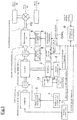
- FIG. 1 is a block diagram illustrating the entire configuration of a hybrid vehicle including a control device for a hybrid vehicle of the embodiment.
- the hybrid vehicle 100 includes an engine E, a motor M, a first clutch CL1, a second clutch CL2, and a transmission T/M.
- the hybrid vehicle 100 includes a propeller shaft PS, a final gear (differential) DF, a left front wheel FL (drive wheel), and a right front wheel FR (drive wheel).
- the engine E and motor M are the drive sources of the hybrid vehicle.
- the hybrid type of the hybrid vehicle 100 is not limited to a parallel type and it may be a series type.
- the engine E is, for example, a gasoline engine or diesel engine, etc.
- the engine E controls an valve opening of a throttle valve based on a control command from an engine controller 1 described below.
- an engine position detector S1 that detects engine speed is arranged for an output shaft of the engine E.
- the motor M is such as a synchronous motor generator made by embedding a permanent magnet to a rotor and winding a stator coil to a stator. Also, the motor M operates by electric power from the a battery 3a.
- An inverter 3 drives by a control command from a motor controller 2 described later, converts the electric power from the battery 3a, and outputs three-phase AC power to the motor M.
- the rotor (output shaft) of the motor is connected to the input shaft of the transmission T/M via the second clutch CL2. Accordingly, the motor M operates as an electric motor for rotationally driving the drive wheels FL and FR upon receipt of electric power supply from the inverter 3. More, when the rotor is rotating by an external force during braking, the motor M functions as a power generator (generator) to generate an electromotive force to both ends of the stator coil and charges the battery 3a (regeneration). To the output shaft of the motor M, a motor position detector S2 is arranged for detecting a motor rotation speed.
- the electric air conditioner 3b operates by electric power from the battery 3a.
- a compressor of the electric air conditioner 3b is not connected to the engine with a belt like in a gasoline vehicle that only has an engine as the drive source but uses the battery 3b as its power source. Further, as to the electric air conditioner 3b, not only the compressor but also other components included in the electric air conditioner 3b consume the electric power of the battery 3a to operate the electric air conditioner 3b. For this reason, when the electric air conditioner 3b is operated, the battery power consumption greatly changes
- the first clutch CL1 includes such as a hydraulic single-disk clutch interposed between the engine E and motor M.
- the first clutch CL1 performs fastening-releasing operation including slip-fastening (slipping) and slip-releasing by the control oil pressure generated by a first clutch oil pressure unit 5 based on a control command from a first clutch controller 4 described later.
- the second clutch CL2 includes such as a hydraulic multi-disk clutch interposed between the motor M and the transmission T/M.
- the second clutch CL2 performs fastening-releasing operation including slip-fastening and slip-releasing by the control oil pressure generated by the second clutch oil pressure unit 7 based on the control command from a second clutch controller 6 described later.
- the torque capacity of the first clutch CL1 and the torque capacity of the second clutch CL2 may change continuously according to the supplied oil pressure.
- the fist clutch oil pressure unit 5 and the second clutch oil pressure unit 7 generate control oil pressure by an oil pressure circuit including the control valve not shown in the drawings. Then, by variably controlling the control oil pressure, the torque capacity of the first clutch CL1 and the torque capacity of the second clutch CL2 can be continuously changed.
- the transmission T/M is a transmission that automatically switches the transmission gear ratio of stepped control, for example, "five forward stages and one backward stage” and “six forward stages and one backward stage”, etc., and continuously variable transmission (CVT) gear ratio according to the driving state such as the speed of the vehicle, an accelerator opening, etc.
- An output shaft of the transmission T/M is connected to right and left front wheels (drive wheels), or FL and FR, via a propeller shaft PS and final gear DF.
- the transmission T/M performs an gear shift operation by the control oil pressure generated by a transmission oil pressure unit 9 based on the control command from a transmission controller 8.
- An input shaft of the transmission T/M includes a T/M input rotation detector S3 for detecting the input rotation speed.
- An output shaft of the transmission T/M includes a T/M output rotation detector S4 for detecting output rotation speed.
- the control device includes an engine controller 1, a motor controller 2, an inverter 3, a battery 3a, a first clutch controller 4, a first clutch oil pressure unit 5, a second clutch controller 6, a second clutch oil pressure unit 7, a transmission controller 8, a transmission oil pressure unit 9, and an integrated controller 10 as shown in FIG. 1 . Additionally, the engine controller 1, the motor controller 2, the first clutch controller 4, the transmission controller 8, and the integrated controller 10 are connected with CAN communication line L to enable exchange of information.
- engine speed information is input from an engine speed sensor not shown in the drawings.
- the engine controller 1 In response to a target engine torque command from the integrated controller 10, the engine controller 1 outputs a command for controlling an engine operation point, for example, to a throttle valve actuator not shown in the drawings. Further, the engine speed information is supplied to the integrated controller 10 through the CAN communication line L.
- the motor controller 2 To the motor controller 2, information is input from the motor position detector S2 that detects rotor rotation position of the motor M. In the response to a target motor rotation speed command from the integrated controller 10, the motor controller 2 outputs a command for controlling the motor rotation speed of the motor M to the inverter 3.
- the first clutch controller 4 inputs sensor information from a clutch oil pressure sensor and clutch stroke sensor, etc., not shown in the drawings. Then, the first clutch controller 4 outputs, in response to the first clutch oil pressure command from the integrated controller 10, a command to control fastening, slipping (slip-fastening), and releasing of the first clutch CL1, to the first clutch oil pressure unit 5.
- the second controller 6 outputs, in response to the second clutch control command from the integrated controller 10, a command to control fastening, slipping (slip-fastening), and releasing of the second clutch CL2 to the second clutch oil pressure unit 7.
- the transmission controller 8 To the transmission controller 8, sensor information from an accelerator opening sensor (not shown in the drawings) that detects opening of the accelerator operated by a driver and vehicle speed sensor is input. Then, the transmission controller 8, in response to a shift command from the integrated controller 10, outputs a command to control the transmission oil pressure to the transmission oil pressure unit 9.
- the transmission oil pressure unit 9 includes an actuator, an oil pressure circuit, and a control valve, which are not shown in the drawings. More, the transmission oil pressure unit 9 generates a predetermined control oil pressure on a basis of a control command from the transmission controller 8and the transmission oil pressure unit 9 performs a gear shift operation (up shifting and down shifting) of the transmission T/M in accordance with the control oil pressure.
- the integrated controller 10 manages energy consumed by the entire vehicle 100, and in order to drive the vehicle at its maximum efficiency, controls the motor M and engine E, etc.
- various sensor signals from an engine position detector S1, a motor position detector S2, a T/M input rotation detector S3, and a T/M input rotation detector S4, etc., and various types of information obtained via the CAN communication line are input.
- the integrated controller 10 performs operation control of the engine E by a control command sent to the engine controller 1, and performs operation control (motor output torque and motor output speed) of the motor M by a control command sent to the motor controller 2. Also, the integrated controller 10 performs fastening, slipping, and releasing controls for the first clutch CL1 by an oil pressure control command sent to the first clutch controller 4, and fastening, slipping, releasing controls for the second clutch CL2 by an oil pressure control command sent to the second clutch controller 6. The integrated controller 10 controls the transmission oil pressure unit 9 by sending a transmission control command to the transmission controller 8.
- FIG. 2 is a block diagram illustrating the configuration of the integrated controller 10.
- the integrated controller 10 is configured from a CPU, ROM, etc., and includes the following structures as a function block of various types of functions executed by the CPU, etc.
- the integrated controller 10 includes a target driving force calculation unit 11, a charge-discharge output calculation unit 12, an air conditioner managing unit 13, an engine output calculation unit 14, a correction determination unit 15, a driving force correction unit 16, a request output calculation unit 17, and an operation point command sending unit 18. Additionally, the configuration of the integrated controller 10 is not limited to the configuration shown in FIG. 2 and includes other configuration for the vehicle control.
- the target driving force calculation unit 11 calculates a target driving force (P t0 ) based on an accelerator opening (APO) and vehicle speed (V).
- the target driving force is a target value of the driving force transmitted to the drive wheels PR and PL from the drive source.
- the target driving force is the target value for traveling with the driving force requested by a driver such as by an operation of an accelerator or the like which are operated by the driver.
- a map indicating correlation between an accelerator opening, vehicle speed, and a target driving force is recorded in advance. Then, the target driving force calculation unit 11 calculates a target driving force (P t0 ) by referencing the map to an input of an accelerator opening (APO) and vehicle speed (V).
- the charge-discharge output calculation unit 12 calculates a charge-discharge output based on an SOC of the battery 3a.
- the charge-discharge output is an output of the engine E or an input and output of the motor M required when charging or discharging the battery by a system request.
- the charge-discharge output is an output (system output) requested to a drive source by a system request.
- the SOC is a value indicating a charge state of the battery 3a and is input to the charge-discharge output calculation unit 12 from a battery controller not shown in the drawings. In order to avoid battery 3a to become a overdischarge state or overcharge state, an appropriate SOC range is set in advance.
- the charge-discharge output calculation unit 12 calculates an output of the motor M so as to discharge the battery 3a.
- the charge-discharge output calculation unit 12 calculates an output of the engine E (driving force of the engine) so as to charge the battery 3a. Then, the charge-discharge output calculation unit 12 calculates a charge-discharge output (P s ) from the power of the engine E or motor M so that the SOC of the battery 3a is within the appropriate range.
- the air conditioner managing unit 13 manages an operating state of the electric air conditioner 3b and electric power consumption consumed by the electric air conditioner 3b.
- the operating state of the electric air conditioner 3b indicates an ON/OFF state of the electric air conditioner 3b and set temperature of the air conditioner, etc.
- the air conditioner managing unit 13 outputs an ON/OFF switching signal of the electric air conditioner 3b to the correction determination unit 15.
- the air conditioner managing unit 13 calculates power consumption (P w ) consumed by the electric air conditioner 3b from outside air temperature and set temperature of the electric air conditioner 3b, etc., and outputs information of the power consumption (P w ) to the driving force correction unit 16 and engine output calculation unit 14. More, since the electric air conditioner 3b uses the battery 3a as its power source, power consumption consumed by the electric air conditioner 3b corresponds to the electric power consumption consumed by the battery 3a.
- the engine output calculation unit 14 calculates an engine output (P E ) required to generate power consumption (P W ) consumed by the electric air conditioner 3b at the motor M.
- the engine output (P E ) corresponds to the amount of power generated by the motor M when the motor M is operated as a power generator by driving the engine E and is equal to the output torque of the engine E.
- the correction determination unit 15 determines whether or not to correct a target driving force (P t0 ) based on the present vehicle speed and accelerator opening of the vehicle. Also, the correction determination unit 15 determines whether or not to correct the target driving force (P t0 ) based on the operation mode of the hybrid vehicle. The correction determination unit 15 determines whether or not to perform the correction when the electric air conditioner 3b is in a ON state. The determination result by the correction determination unit 15 is output to the driving force correction unit 16.
- the driving force correction unit 16 corrects the target driving force (P t0 ) in accordance with the determination result determined by the correction determination unit 15 and outputs the corrected target driving force (P t1 ) to the request output calculation unit 17.
- the driving force correction unit 16 calculates a correction amount of the target driving force (P t0 ).
- the correction amount is a value obtained by converting the electric power (output from the battery 3a) required to operate the electric air conditioner 3b to the driving force of the drive source. In other words, the correction amount is the driving force that corresponds to the power consumption consumed by the electric air conditioner 3b. Further, the driving force correction unit 16 corrects the target driving force (P t0 ) by subtracting the correction amount from the target driving force (P t0 ).
- the driving force correction unit 16 When the correction determination unit 15 determines not to correct the target driving force (P t0 ), the driving force correction unit 16 outputs the target driving force (P t0 ) as the target driving force (P t1 ) to the request output calculation unit 17 without correction.
- the request output calculation unit 17 calculates a request output (P d ) by adding the target driving force (P t1 ), charge-discharge output (P s ), and auxiliary output (P a ).
- the auxiliary output corresponds to the driving force requested by the drive source in order to operate auxiliaries. For example, when starting travel of a vehicle, an auxiliary output is the power required for vehicle travel.
- the request output calculation unit 17 calculates the auxiliary output in accordance with kinds of the auxiliaries to be operated. To the auxiliaries, for example, an oil pump is included.
- the request output is an output requested to a drive source in order to satisfy a drive request based on the accelerator operation by the driver and system request.
- the request output calculation unit 17 calculates the request output (P d ) by adding the engine output (P E ) to the output obtained by adding the target driving force (P t1 ), charge-discharge output (P s ), and auxiliary output (P a ).
- the request output calculation unit 17 outputs the request output (P d ) to the operation point command sending unit 18.
- the operation point command sending unit 18 calculates each of an operation point of the engine E and an operation point of the motor M in order to output request output (P d ) from the drive source.
- the operation point of the engine E is indicated with an engine torque and engine speed and is an operation point for outputting the request output to the engine from the engine E in a good fuel-efficiency state.
- the operation point command sending unit 18 calculates a torque command of the engine E from the present rotation speed of the engine E and operation point of the engine E, and outputs the command to the engine controller 1.
- the operation point command sending unit 18 calculates a rotation speed command of the motor M based on the present rotation speed of the motor M so as to drive the motor M at the operation point and outputs the command to the motor controller 2. Also, the operation point command sending unit 18 outputs such as a shift command so that the request output (P d ) is output from the drive source.
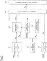
- FIG. 3 is a flowchart illustrating a control flow of the integrated controller 10.
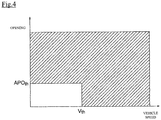
- FIG. 4 is a graph illustrating a correction range in which correction is performed concerning the speed of a vehicle and accelerator opening.
- FIG. 5 is a graph illustrating a correction range in which a correction is performed concerning ON/OFF of an air conditioner and a traveling mode of the vehicle. Additionally, the integrated controller 10 repeats the following control flow in a predetermined cycle.
- step S1 the target driving force calculation unit 11 calculates a target driving force (P t0 ) to the drive wheel.
- the charge-discharge output calculation unit 12 calculates a charge-discharge output (P s ) by a system request.
- step S3 the air conditioner managing unit 13 determines whether or not the electric air conditioner 3b is in operation. When the electric air conditioner 3b is in operation, in step S4, the engine output calculation unit 14 calculates an engine output (P E ) based on the power consumption consumed by the electric air conditioner 3b.
- step S5 the correction determination unit 15 determines whether or not the drive state of the vehicle is within a correction range.
- the driving state of the vehicle is indicated by vehicle speed and accelerator opening of the vehicle.
- the correction range is the range in which the target driving force (P t0 ) is corrected by the driving force correction unit 16.
- a threshold value for indicating a correction range is set in advance.
- the threshold value is set by a threshold value for the vehicle speed of the vehicle (V th ) and a threshold value (APO th ) of the accelerator opening.
- the correction range is the range in which the vehicle speed of the vehicle is the vehicle speed threshold value (V th ) or more or in which the accelerator opening is the opening threshold value (APO th ) or more.
- the range in which the vehicle speed of the vehicle is less than the vehicle speed threshold value (V th ) and also in which the accelerator opening is less than the opening threshold value (APO th ) is excluded from the correction range.
- the no correction range is a range in which a creeping state of the vehicle is shown in vehicle speed and accelerator opening. In other words, when the driving state is in a creeping state, correction of the target driving force (P t0 ) is not performed.
- the correction range is shown with oblique lines.
- the correction determination unit 15 determines that the driving state is within a correction range when the present vehicle speed is the vehicle speed threshold value (V th ) or more, or when the present accelerator opening is the opening threshold value (APO th ) or more. On the other hand, the correction determination unit 15 determines that the driving state is out of the correction range when the present vehicle speed is less than the vehicle speed threshold value (V th ) and when the present accelerator opening is less than the opening threshold value (APO th ).
- the correction range is similarly set for the cases in which the drive mode of the vehicle is an HEV mode and in which the drive mode of the vehicle is the EV mode. Accordingly, when the electric air conditioner 3b is in a ON state and when the driving state is within a correction range, a target driving force (P t ) is corrected when the drive mode is the HEV mode, and the target driving force (P t ) is also corrected when the drive mode is in the EV mode.
- the correction range is not set. Accordingly, when the electric air conditioner 3b is in the OFF state, the target driving force (P t ) is not corrected.
- the driving force correction unit 16 calculates a driving force of the drive source which corresponds to the power consumption consumed by the electric air conditioner 3b in step S6.
- the driving force correction unit 16 corrects the target driving force (P t0 ) by performing subtraction processing.
- the driving force correction unit 16 subtracts the calculated driving force from the target driving force (P t0 ) as the subtraction processing.
- step S8 the request output calculation unit 17 calculates the auxiliary output (P a ) and by adding the corrected target driving force (P t1 ), charge-discharge output (P s ), engine output (P E ) and auxiliary output (P a ), calculates a request output (P d ).
- the request output calculation unit 17 calculates the request output (P d ) by adding the engine output (P E ) to the charge-discharge output (P s ), and further adding the target driving force (P t1 ) after correction and auxiliary output (P a ).
- the request output calculation unit 17 calculates an auxiliary output (P a ) in step S9 and by adding the target driving force (P t0 ), charge-discharge output (P s ), engine output (P E ), and auxiliary output (P a ), calculates the request output (P d ). In this way, the request output calculation unit 17 calculates the request output (P d ) by adding the engine output (P E ) to the charge-discharge output (P s ) and further adding the target driving force (P t1 ) to which the subtraction processing is not performed and the auxiliary output (P a ).
- the request output calculation unit 17 calculates the auxiliary output (P a ) in step S10 and by adding the target driving force (P t0 ), charge-discharge output (P s ), and auxiliary output (P a ), calculates a request output (P d ).
- step S11 the request output calculation unit 17 calculates an operation point which corresponds to the calculated request output.
- step S12 the operation point command sending unit 18 calculates such of a torque command value for engine E so as to operate engine E and/or motor M at the operation point and outputs the result to the engine controller 1, etc.
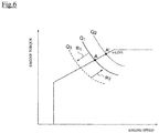
- FIG. 6 is a graph illustrating an equal output line of an ⁇ -line and request outputs.
- the horizontal axis of FIG. 6 shows the rotation speed and the vertical axis shows the torque of the engine E.
- the request output becomes a value to which a target driving force (P t1 ) and charge input and output (P s ) are added.
- the target driving force (P t1 ) is not corrected by the driving force correction unit 16, and is the value same as the target driving force (P t0 ).
- the output requested to the engine E is represented with an equal output line of graph Q 1 .
- An operation point of the engine E with respect to the request output of the engine E is represented by an intersection point (point A) with the ⁇ -line. Further, ⁇ -line is the line that connects the operation points at which the output efficiency of the engine E is high.
- the electric air conditioner 3b is switched from an OFF state to an ON state in a state in which the engine E is driving at the operation point A.
- the electric air conditioner 3b needs to drive the engine E and generate power in the motor M for the power amount consumed by the battery 3a.
- the target driving force (P 0 ) is raised in order to make up the power generated by the motor without changing the input and output of the drive source requested to the system, the request output is raised and the request output of the engine E becomes the output on the graph Q 2 that is higher than the output on the graph Q 1 .
- the operation point A of the engine E becomes the operation point A' (an intersection point of the equal output line Q 2 and the ⁇ -line).
- the electric air conditioner 3b becomes an ON state
- the request output to the engine E becomes high and by switching of the electric air conditioner 3b from OFF to ON, the rotation speed of the engine E increases.
- the electric air conditioner 3b when the electric air conditioner 3b is to be switched from an ON state to an OFF state in a state where the amount of power generated by the motor that corresponds to power consumption consumed by the electric air conditioner 3b is added to the target driving force, the amount of power generated by the motor M that corresponds to the power consumption consumed by the electric air conditioner 3b becomes unnecessary. Accordingly, the driving force that corresponds to the amount of generated power is no longer added to the target driving force and thus the target driving force lowers and the request output to the engine E also decreases. For this reason, the rotation speed of the engine E lowers due to switching of the electric air conditioner 3b from ON to OFF. That is, when the control that is different from the one in the present embodiment is performed, a rotation fluctuation is generated to the engine by the operation of the air conditioner.
- the output requested to the engine E when the electric air conditioner 3b is in an OFF state is represented by the equal output line of graph Q 1 and the operation point of the engine E is represented by the point A on the graph Q 1 .
- the electric air conditioner 3b is switched from an OFF state to an ON state.
- a driving force that corresponds to the power consumption consumed by the electric air conditioner 3b is subtracted from the target driving force.
- the request output to the engine E lowers from the graph Q 1 to graph Q 3 (corresponds to an arrow R 1 in FIG. 6 ).
- an engine output (P E ) required to generate power consumption consumed by the electric air conditioner 3b in the motor M is added to the output requested by the system.
- the request output to the engine E becomes high for the amount of the driving force which is subtracted by the subtraction processing to the target driving force, and the request output to the engine E increases from the graph Q 3 to the graph Q 1 (corresponds to an arrow R 2 in FIG. 6 ).
- request output to the engine E does not change even when the electric air conditioner 3b is changed from the OFF state to the ON state, and the operation point for the engine E becomes the point A. Accordingly, rotation speed of the engine E does not change greatly and is kept stable.
- FIG. 7 describes a time chart when the electric air conditioner 3b switches from the OFF state to the ON state and then the electric air conditioner 3b switches from the ON state to the OFF state.
- FIG. 7 is a graph for describing a time chart, and (a) is a graph showing switching between ON and OFF of the electric air conditioner 3b, (b) is a graph showing characteristics of the power generation amount of the motor M, and (c) is a graph showing characteristics of the driving force transmitted to the drive wheels FR and FL.
- the electric air conditioner 3b switches from an OFF state to an ON state.
- the power generation amount of the motor M becomes high.
- the power generation amount of the motor M is rapidly raised (raised so as to create a pulse)
- a decrease amount in the driving force transmitted to the driving wheels FR and FL increases and there is a risk that an occupant of the vehicle feels uncomfortable.
- the power generation amount by the motor M is raised gradually.
- the driving force correction unit 16 gradually increases the subtraction amount along with elapse of time when subtracting the driving force of the drive source that corresponds to the power consumption (power generation amount of the motor M) consumed by the electric air conditioner 3b from the target driving force.
- the driving force correction unit 16 performs subtraction processing in a manner so as to make the subtraction amount equal to the power consumption consumed by the electric air conditioner 3b (the power generation amount (P x ) of the motor M) at the time t 2 .
- the engine output calculation unit 14, by corresponding to the change rate limitation of the driving force by the driving force correction unit 16, limits the change rate of the engine output (P E ).
- the engine output calculation unit 14 gradually increases the engine output (P E ) along with elapse of time.
- the engine output calculation unit 14 calculates the engine output (P E ) so that the engine output (P E ) is equal to the power consumption (the power generation amount of the motor M) consumed by the electric air conditioner 3b at the time t 2 .
- the power generation amount of the motor M between the time t 1 to time t 2 gradually increases in a predetermined inclination.
- the subtraction amount from the target driving force (P t1 ) and engine output (P E ) also increase gradually in a predetermined inclination.
- the driving force of the drive wheels gradually decreases as shown in graph (c) in FIG. 7 , and the driving force becomes smaller than P y (see graph (c) in FIG. 7 ).
- the driving force can be controlled in a way to avoid the occupant from feeling uncomfortable (shock).
- the power generation amount by the motor M becomes smaller than the power consumption (power consumption amount) consumed by the electric air conditioner 3b, a shortage in the power generation amount of the motor M (corresponds to the range shown as S 1 in graph (b)) can be covered by discharge of the battery 3a.
- electric air conditioner 3b is switched from an ON state to an OFF state.
- power generation by the motor M to supply the power for the amount consumed by the electric air conditioner 3b becomes unnecessary.
- the power generation amount by the motor M is rapidly made small, the amount of increase in the driving force transmitted to the drive wheels FR and FL becomes large and may lead to discomfort to the occupant of the vehicle. For this reason, when making power generation by the motor M for supplying the power consumption consumed by the electric air conditioner 3b to zero , power generation amount of the motor M is gradually reduced.
- the driving force correction unit 16 reduces the driving force of the drive source that corresponds to the power consumption (the power generation amount by the motor M) consumed by the electric air conditioner 3b and gradually increases the increase amount along with elapse of time when increasing the target driving force.
- the driving force correction unit 16 calculates the target driving force (P t1 ) as the target driving force (P t0 ) so that the amount of increase at the point of time t 4 corresponds to the subtraction amount in the subtraction processing. Also, the engine output calculation unit 14, in correspondence with the change rate of the driving force in the driving force correction unit 16, limits the change rate of the engine output (P E ). Specifically, the engine output calculation unit 14 gradually reduces the engine output (P E ), which corresponds to the power consumption consumed by the electric air conditioner 3b, along with the elapse of time. Then, the engine output calculation unit 14 calculates the engine output (P E ) so that the engine output (P E ) becomes zero at the time t 4 .
- the power generation amount of the motor M from the time t 3 to time t 4 gradually decreases in a predetermined inclination.
- the increase amount of the target driving force (P t1 ) gradually increases in a predetermined inclination and engine output (P E ) gradually decreases in a predetermined inclination.
- the driving force of the drive wheels gradually increases as shown in graph (c) in FIG. 7 , and becomes P y . In this way, when switching the electric air conditioner 3b from ON to OFF, to avoid the occupant from feeling uncomfortable (shock), the driving force can be controlled.
- the driving force that corresponds to the power consumption consumed by the electric air conditioner 3b is subtracted from the target driving force (P t0 ) and also an engine output (P E ) required to generate the power consumption consumed by the electric air conditioner 3b by the motor M is added to the output requested by the system and calculates the request output to the drive source.
- P E engine output
- fluctuation in engine speed due to operation of the electric air conditioner 3b can be suppressed.
- the operation point of the engine can be maintained above the ⁇ -line.
- the request output is calculated by subtracting the driving force that corresponds to the power consumption consumed by the electric air conditioner 3b from the target driving force (P t0 ) and by adding the output that corresponds to the power consumption consumed by the electric air conditioner to the output requested by the system.
- P t0 target driving force
- the request output is calculated by subtracting the driving force that corresponds to the power consumption consumed by the electric air conditioner 3b from the target driving force (P t0 ) and by adding the output that corresponds to the power consumption consumed by the electric air conditioner to the output requested by the system.
- addition processing to the output requested from the system is performed to discharge electric power for the amount of power consumption consumed by the electric air conditioner 3b by the battery 3a. For this reason, the output that corresponds to the power consumption(the output added to the request output from the system) consumed by the electric air conditioner 3b is equal to the engine output (P E ) of the HEV mode.
- the above target driving force calculation unit 11 corresponds to "target driving force calculation unit” according to the present invention and the air conditioner managing unit 13 corresponds to the “air conditioner managing unit” according to the present invention.
- the charge-discharge output calculation unit 12, air conditioner managing unit 13, engine output calculation unit 14, correction determination unit 15, driving force correction unit 16, request output calculation unit 17, and operation point command sending unit 18 correspond to "control unit” according to the present invention.
Landscapes
- Engineering & Computer Science (AREA)
- Chemical & Material Sciences (AREA)
- Combustion & Propulsion (AREA)
- Transportation (AREA)
- Mechanical Engineering (AREA)
- Automation & Control Theory (AREA)
- Electric Propulsion And Braking For Vehicles (AREA)
- Hybrid Electric Vehicles (AREA)
- Control Of Vehicle Engines Or Engines For Specific Uses (AREA)
Abstract
Description
- The present invention relates to a control device for a hybrid vehicle and its control method.
- As a conventional control device of a vehicle, a control device controls load of a power source based on a target output torque determined by calculating a target output of the power source based on the target driving force, calculating a target output rotation speed based on the target output, and calculating a target output torque of the power source for achieving the target driving force based on the target driving force. The control device calculates a target output (P2) by adding an output torque (Paux) for maintaining idling operation of the power source to a target output torque (P) and controls a load to the power source so that the output torque of the drive source to become the target output (P2).
- [Patent Document 1]
JP 2001-253270 A - However, in the control device, when operating the air conditioner, the torque required for operating an air conditioner is added to the output torque of the power source, an equal output line of the target output is raised and thus the engine speed also becomes high. For this reason, there is a problem that engine rotation is fluctuated by an operation of the air conditioner.
- A problem to be solved by the invention is to provide a control device which can suppress fluctuation in the engine speed due to operation of an air conditioner.
- In the present invention, a request output is calculated by adding a target driving force of the drive source to a system output requested to a drive source by a system request and an operation point for an engine is calculated for optimally driving an engine in response to the request output for controlling the engine to drive at the operation point. Also, in the present invention, in order to solve the above problem, when an air conditioner is in an ON state, a driving force which corresponds to electric power consumption consumed by the air conditioner is subtracted from the target driving force and the request output is calculated by adding an engine output required to generate the power consumption by a motor to the system output.
- According to the present invention, when the air conditioner becomes an On state, the driving force which corresponds to the electric power consumption consumed by the air conditioner is subtracted from the target driving force and the engine output which corresponds to the subtracted driving force is added to the output requested to the system, and thus an operation point of the engine does not greatly vary depending on the operation of the air conditioner. As a result, fluctuation of an engine speed due to operation of the air conditioner can be suppressed.
-
- [
FIG. 1] FIG. 1 is a block diagram illustrating an entire configuration of a hybrid vehicle according to an embodiment of the present invention. - [
FIG. 2] FIG. 2 is a block diagram illustrating a configuration of an integrated controller inFIG. 1 . - [
FIG. 3] FIG. 3 is a flowchart illustrating a control flow of the integrated controller ofFIG. 2 . - [
FIG. 4] FIG. 4 is a graph illustrating a range to which a correction is performed concerning the speed and accelerator opening of a vehicle. - [
FIG. 5] FIG. 5 is a graph illustrating a range to which a correction is performed concerning ON/OFF of an air conditioner and a traveling mode of the vehicle. - [
FIG. 6] FIG. 6 is a graph illustrating an equal output line of an α-line and request outputs. - [
FIG. 7] FIG. 7 is graphs to describe a time chart in relation to ON/OFF of the electric air conditioner, the amount of power generation, and driving force. Graph (a) is a graph illustrating characteristics of ON/OFF of the electric air conditioner, (b) is a graph illustrating characteristics of power generation amount, and (c) is a graph illustrating driving force characteristics. - In the following, embodiments of the present invention are explained with reference to the drawings.
-
FIG. 1 is a block diagram illustrating the entire configuration of a hybrid vehicle including a control device for a hybrid vehicle of the embodiment. As shown inFIG. 1 , the hybrid vehicle 100 includes an engine E, a motor M, a first clutch CL1, a second clutch CL2, and a transmission T/M. The hybrid vehicle 100 includes a propeller shaft PS, a final gear (differential) DF, a left front wheel FL (drive wheel), and a right front wheel FR (drive wheel). The engine E and motor M are the drive sources of the hybrid vehicle. Further, the hybrid type of the hybrid vehicle 100 is not limited to a parallel type and it may be a series type. - The engine E is, for example, a gasoline engine or diesel engine, etc. The engine E controls an valve opening of a throttle valve based on a control command from an
engine controller 1 described below. Note that, for an output shaft of the engine E, an engine position detector S1 that detects engine speed is arranged. - The motor M is such as a synchronous motor generator made by embedding a permanent magnet to a rotor and winding a stator coil to a stator. Also, the motor M operates by electric power from the a
battery 3a. Aninverter 3 drives by a control command from amotor controller 2 described later, converts the electric power from thebattery 3a, and outputs three-phase AC power to the motor M. - The rotor (output shaft) of the motor is connected to the input shaft of the transmission T/M via the second clutch CL2. Accordingly, the motor M operates as an electric motor for rotationally driving the drive wheels FL and FR upon receipt of electric power supply from the
inverter 3. More, when the rotor is rotating by an external force during braking, the motor M functions as a power generator (generator) to generate an electromotive force to both ends of the stator coil and charges thebattery 3a (regeneration). To the output shaft of the motor M, a motor position detector S2 is arranged for detecting a motor rotation speed. - The
electric air conditioner 3b operates by electric power from thebattery 3a. A compressor of theelectric air conditioner 3b is not connected to the engine with a belt like in a gasoline vehicle that only has an engine as the drive source but uses thebattery 3b as its power source. Further, as to theelectric air conditioner 3b, not only the compressor but also other components included in theelectric air conditioner 3b consume the electric power of thebattery 3a to operate theelectric air conditioner 3b. For this reason, when theelectric air conditioner 3b is operated, the battery power consumption greatly changes - The first clutch CL1 includes such as a hydraulic single-disk clutch interposed between the engine E and motor M. The first clutch CL1 performs fastening-releasing operation including slip-fastening (slipping) and slip-releasing by the control oil pressure generated by a first clutch
oil pressure unit 5 based on a control command from afirst clutch controller 4 described later. - The second clutch CL2 includes such as a hydraulic multi-disk clutch interposed between the motor M and the transmission T/M. The second clutch CL2 performs fastening-releasing operation including slip-fastening and slip-releasing by the control oil pressure generated by the second clutch
oil pressure unit 7 based on the control command from asecond clutch controller 6 described later. - The torque capacity of the first clutch CL1 and the torque capacity of the second clutch CL2 may change continuously according to the supplied oil pressure. Also, the fist clutch
oil pressure unit 5 and the second clutchoil pressure unit 7 generate control oil pressure by an oil pressure circuit including the control valve not shown in the drawings. Then, by variably controlling the control oil pressure, the torque capacity of the first clutch CL1 and the torque capacity of the second clutch CL2 can be continuously changed. - The transmission T/M is a transmission that automatically switches the transmission gear ratio of stepped control, for example, "five forward stages and one backward stage" and "six forward stages and one backward stage", etc., and continuously variable transmission (CVT) gear ratio according to the driving state such as the speed of the vehicle, an accelerator opening, etc. An output shaft of the transmission T/M is connected to right and left front wheels (drive wheels), or FL and FR, via a propeller shaft PS and final gear DF. The transmission T/M performs an gear shift operation by the control oil pressure generated by a transmission
oil pressure unit 9 based on the control command from atransmission controller 8. An input shaft of the transmission T/M includes a T/M input rotation detector S3 for detecting the input rotation speed. An output shaft of the transmission T/M includes a T/M output rotation detector S4 for detecting output rotation speed. - Next, a control device of the hybrid vehicle 100 is explained. The control device includes an
engine controller 1, amotor controller 2, aninverter 3, abattery 3a, afirst clutch controller 4, a first clutchoil pressure unit 5, asecond clutch controller 6, a second clutchoil pressure unit 7, atransmission controller 8, a transmissionoil pressure unit 9, and an integratedcontroller 10 as shown inFIG. 1 . Additionally, theengine controller 1, themotor controller 2, thefirst clutch controller 4, thetransmission controller 8, and theintegrated controller 10 are connected with CAN communication line L to enable exchange of information. - To the
engine controller 1, engine speed information is input from an engine speed sensor not shown in the drawings. In response to a target engine torque command from theintegrated controller 10, theengine controller 1 outputs a command for controlling an engine operation point, for example, to a throttle valve actuator not shown in the drawings. Further, the engine speed information is supplied to the integratedcontroller 10 through the CAN communication line L. - To the
motor controller 2, information is input from the motor position detector S2 that detects rotor rotation position of the motor M. In the response to a target motor rotation speed command from theintegrated controller 10, themotor controller 2 outputs a command for controlling the motor rotation speed of the motor M to theinverter 3. - The
first clutch controller 4 inputs sensor information from a clutch oil pressure sensor and clutch stroke sensor, etc., not shown in the drawings. Then, thefirst clutch controller 4 outputs, in response to the first clutch oil pressure command from theintegrated controller 10, a command to control fastening, slipping (slip-fastening), and releasing of the first clutch CL1, to the first clutchoil pressure unit 5. - To the second
clutch controller 6, sensor information from a clutch oil pressure sensor and clutch stroke sensor, etc., not shown in the drawings is input. Thesecond controller 6 outputs, in response to the second clutch control command from the integratedcontroller 10, a command to control fastening, slipping (slip-fastening), and releasing of the second clutch CL2 to the second clutchoil pressure unit 7. - To the
transmission controller 8, sensor information from an accelerator opening sensor (not shown in the drawings) that detects opening of the accelerator operated by a driver and vehicle speed sensor is input. Then, thetransmission controller 8, in response to a shift command from the integratedcontroller 10, outputs a command to control the transmission oil pressure to the transmissionoil pressure unit 9. - The transmission
oil pressure unit 9 includes an actuator, an oil pressure circuit, and a control valve, which are not shown in the drawings. More, the transmissionoil pressure unit 9 generates a predetermined control oil pressure on a basis of a control command from the transmission controller 8and the transmissionoil pressure unit 9 performs a gear shift operation (up shifting and down shifting) of the transmission T/M in accordance with the control oil pressure. - The
integrated controller 10 manages energy consumed by the entire vehicle 100, and in order to drive the vehicle at its maximum efficiency, controls the motor M and engine E, etc. To theintegrated controller 10, various sensor signals from an engine position detector S1, a motor position detector S2, a T/M input rotation detector S3, and a T/M input rotation detector S4, etc., and various types of information obtained via the CAN communication line are input. - Then, the
integrated controller 10 performs operation control of the engine E by a control command sent to theengine controller 1, and performs operation control (motor output torque and motor output speed) of the motor M by a control command sent to themotor controller 2. Also, theintegrated controller 10 performs fastening, slipping, and releasing controls for the first clutch CL1 by an oil pressure control command sent to the firstclutch controller 4, and fastening, slipping, releasing controls for the second clutch CL2 by an oil pressure control command sent to the secondclutch controller 6. Theintegrated controller 10 controls the transmissionoil pressure unit 9 by sending a transmission control command to thetransmission controller 8. - Next, the configuration of the
integrated controller 10 is explained.FIG. 2 is a block diagram illustrating the configuration of theintegrated controller 10. Theintegrated controller 10 is configured from a CPU, ROM, etc., and includes the following structures as a function block of various types of functions executed by the CPU, etc. Theintegrated controller 10 includes a target drivingforce calculation unit 11, a charge-dischargeoutput calculation unit 12, an airconditioner managing unit 13, an engineoutput calculation unit 14, acorrection determination unit 15, a drivingforce correction unit 16, a requestoutput calculation unit 17, and an operation pointcommand sending unit 18. Additionally, the configuration of theintegrated controller 10 is not limited to the configuration shown inFIG. 2 and includes other configuration for the vehicle control. - The target driving
force calculation unit 11 calculates a target driving force (Pt0) based on an accelerator opening (APO) and vehicle speed (V). The target driving force is a target value of the driving force transmitted to the drive wheels PR and PL from the drive source. In other words, the target driving force is the target value for traveling with the driving force requested by a driver such as by an operation of an accelerator or the like which are operated by the driver. To the target drivingforce calculation unit 11, a map indicating correlation between an accelerator opening, vehicle speed, and a target driving force is recorded in advance. Then, the target drivingforce calculation unit 11 calculates a target driving force (Pt0) by referencing the map to an input of an accelerator opening (APO) and vehicle speed (V). - The charge-discharge
output calculation unit 12 calculates a charge-discharge output based on an SOC of thebattery 3a. The charge-discharge output is an output of the engine E or an input and output of the motor M required when charging or discharging the battery by a system request. In other words, the charge-discharge output is an output (system output) requested to a drive source by a system request. The SOC is a value indicating a charge state of thebattery 3a and is input to the charge-dischargeoutput calculation unit 12 from a battery controller not shown in the drawings. In order to avoidbattery 3a to become a overdischarge state or overcharge state, an appropriate SOC range is set in advance. When a present SOC of thebattery 3a is higher than the appropriate range of SOC, the charge-dischargeoutput calculation unit 12 calculates an output of the motor M so as to discharge thebattery 3a. On the other hand, when the present SOC of thebattery 3a is lower than the appropriate range of SOC, the charge-dischargeoutput calculation unit 12 calculates an output of the engine E (driving force of the engine) so as to charge thebattery 3a. Then, the charge-dischargeoutput calculation unit 12 calculates a charge-discharge output (Ps) from the power of the engine E or motor M so that the SOC of thebattery 3a is within the appropriate range. - The air
conditioner managing unit 13 manages an operating state of theelectric air conditioner 3b and electric power consumption consumed by theelectric air conditioner 3b. The operating state of theelectric air conditioner 3b indicates an ON/OFF state of theelectric air conditioner 3b and set temperature of the air conditioner, etc. When ON/OFF state of theelectric air conditioner 3b is switched by an occupant, the airconditioner managing unit 13 outputs an ON/OFF switching signal of theelectric air conditioner 3b to thecorrection determination unit 15. Also, the airconditioner managing unit 13 calculates power consumption (Pw) consumed by theelectric air conditioner 3b from outside air temperature and set temperature of theelectric air conditioner 3b, etc., and outputs information of the power consumption (Pw) to the drivingforce correction unit 16 and engineoutput calculation unit 14. More, since theelectric air conditioner 3b uses thebattery 3a as its power source, power consumption consumed by theelectric air conditioner 3b corresponds to the electric power consumption consumed by thebattery 3a. - The engine
output calculation unit 14 calculates an engine output (PE) required to generate power consumption (PW) consumed by theelectric air conditioner 3b at the motor M. The engine output (PE) corresponds to the amount of power generated by the motor M when the motor M is operated as a power generator by driving the engine E and is equal to the output torque of the engine E. - The
correction determination unit 15 determines whether or not to correct a target driving force (Pt0) based on the present vehicle speed and accelerator opening of the vehicle. Also, thecorrection determination unit 15 determines whether or not to correct the target driving force (Pt0) based on the operation mode of the hybrid vehicle. Thecorrection determination unit 15 determines whether or not to perform the correction when theelectric air conditioner 3b is in a ON state. The determination result by thecorrection determination unit 15 is output to the drivingforce correction unit 16. - The driving
force correction unit 16 corrects the target driving force (Pt0) in accordance with the determination result determined by thecorrection determination unit 15 and outputs the corrected target driving force (Pt1) to the requestoutput calculation unit 17. When thecorrection determination unit 15 determines to correct the target driving force (Pt0), the drivingforce correction unit 16 calculates a correction amount of the target driving force (Pt0). The correction amount is a value obtained by converting the electric power (output from thebattery 3a) required to operate theelectric air conditioner 3b to the driving force of the drive source. In other words, the correction amount is the driving force that corresponds to the power consumption consumed by theelectric air conditioner 3b. Further, the drivingforce correction unit 16 corrects the target driving force (Pt0) by subtracting the correction amount from the target driving force (Pt0). - When the
correction determination unit 15 determines not to correct the target driving force (Pt0), the drivingforce correction unit 16 outputs the target driving force (Pt0) as the target driving force (Pt1) to the requestoutput calculation unit 17 without correction. - The request
output calculation unit 17 calculates a request output (Pd) by adding the target driving force (Pt1), charge-discharge output (Ps), and auxiliary output (Pa). The auxiliary output corresponds to the driving force requested by the drive source in order to operate auxiliaries. For example, when starting travel of a vehicle, an auxiliary output is the power required for vehicle travel. The requestoutput calculation unit 17 calculates the auxiliary output in accordance with kinds of the auxiliaries to be operated. To the auxiliaries, for example, an oil pump is included. The request output is an output requested to a drive source in order to satisfy a drive request based on the accelerator operation by the driver and system request. When theelectric air conditioner 3b is in a ON state, because an engine output (PE) is input from the engineoutput calculation unit 14, the requestoutput calculation unit 17 calculates the request output (Pd) by adding the engine output (PE) to the output obtained by adding the target driving force (Pt1), charge-discharge output (Ps), and auxiliary output (Pa). The requestoutput calculation unit 17 outputs the request output (Pd) to the operation pointcommand sending unit 18. - The operation point
command sending unit 18 calculates each of an operation point of the engine E and an operation point of the motor M in order to output request output (Pd) from the drive source. The operation point of the engine E is indicated with an engine torque and engine speed and is an operation point for outputting the request output to the engine from the engine E in a good fuel-efficiency state. Then, the operation pointcommand sending unit 18 calculates a torque command of the engine E from the present rotation speed of the engine E and operation point of the engine E, and outputs the command to theengine controller 1. The operation pointcommand sending unit 18 calculates a rotation speed command of the motor M based on the present rotation speed of the motor M so as to drive the motor M at the operation point and outputs the command to themotor controller 2. Also, the operation pointcommand sending unit 18 outputs such as a shift command so that the request output (Pd) is output from the drive source. - In the following, with reference to
FIG. 3 to FIG. 5 , control flow of theintegrated controller 10 is explained.FIG. 3 is a flowchart illustrating a control flow of theintegrated controller 10.FIG. 4 is a graph illustrating a correction range in which correction is performed concerning the speed of a vehicle and accelerator opening.FIG. 5 is a graph illustrating a correction range in which a correction is performed concerning ON/OFF of an air conditioner and a traveling mode of the vehicle. Additionally, theintegrated controller 10 repeats the following control flow in a predetermined cycle. - In step S1, the target driving
force calculation unit 11 calculates a target driving force (Pt0) to the drive wheel. In step S2, the charge-dischargeoutput calculation unit 12 calculates a charge-discharge output (Ps) by a system request. In step S3, the airconditioner managing unit 13 determines whether or not theelectric air conditioner 3b is in operation. When theelectric air conditioner 3b is in operation, in step S4, the engineoutput calculation unit 14 calculates an engine output (PE) based on the power consumption consumed by theelectric air conditioner 3b. - In step S5, the
correction determination unit 15 determines whether or not the drive state of the vehicle is within a correction range. The driving state of the vehicle is indicated by vehicle speed and accelerator opening of the vehicle. The correction range is the range in which the target driving force (Pt0) is corrected by the drivingforce correction unit 16. To thecorrection determination unit 15, a threshold value for indicating a correction range is set in advance. The threshold value is set by a threshold value for the vehicle speed of the vehicle (Vth) and a threshold value (APOth) of the accelerator opening. Then, the correction range is the range in which the vehicle speed of the vehicle is the vehicle speed threshold value (Vth) or more or in which the accelerator opening is the opening threshold value (APOth) or more. The range in which the vehicle speed of the vehicle is less than the vehicle speed threshold value (Vth) and also in which the accelerator opening is less than the opening threshold value (APOth) is excluded from the correction range. The no correction range is a range in which a creeping state of the vehicle is shown in vehicle speed and accelerator opening. In other words, when the driving state is in a creeping state, correction of the target driving force (Pt0) is not performed. InFIG. 4 , the correction range is shown with oblique lines. - The
correction determination unit 15 determines that the driving state is within a correction range when the present vehicle speed is the vehicle speed threshold value (Vth) or more, or when the present accelerator opening is the opening threshold value (APOth) or more. On the other hand, thecorrection determination unit 15 determines that the driving state is out of the correction range when the present vehicle speed is less than the vehicle speed threshold value (Vth) and when the present accelerator opening is less than the opening threshold value (APOth). - Now, the relationship of the correction range between the operating state of the
electric air conditioner 3b and drive mode is described with reference toFIG. 5 . As shown inFIG. 5 , the correction range is similarly set for the cases in which the drive mode of the vehicle is an HEV mode and in which the drive mode of the vehicle is the EV mode. Accordingly, when theelectric air conditioner 3b is in a ON state and when the driving state is within a correction range, a target driving force (Pt) is corrected when the drive mode is the HEV mode, and the target driving force (Pt) is also corrected when the drive mode is in the EV mode. In this way, for example, when a drive range is within a correction range and when the drive mode is switched from the HEV mode to EV mode, or when the drive mode is switched from the EV mode to the HEV mode, a state of correcting the target driving force (Pt) will be maintained. Further, when the drive range is out of the correction range and when the drive mode is switched from the HEV mode to the EV mode, or when the drive mode is switched form the EV mode to the HEV mode, a state in which the correction is not performed for the target driving force (Pt) is maintained. - On the other hand, when the
electric air conditioner 3b is in the OFF state, the correction range is not set. Accordingly, when theelectric air conditioner 3b is in the OFF state, the target driving force (Pt) is not corrected. - When the driving state is determined to be within the correction range by the determination in step S5, the driving
force correction unit 16 calculates a driving force of the drive source which corresponds to the power consumption consumed by theelectric air conditioner 3b in step S6. In step S7, the drivingforce correction unit 16 corrects the target driving force (Pt0) by performing subtraction processing. The drivingforce correction unit 16 subtracts the calculated driving force from the target driving force (Pt0) as the subtraction processing. In step S8, the requestoutput calculation unit 17 calculates the auxiliary output (Pa) and by adding the corrected target driving force (Pt1), charge-discharge output (Ps), engine output (PE) and auxiliary output (Pa), calculates a request output (Pd). In other words, the requestoutput calculation unit 17 calculates the request output (Pd) by adding the engine output (PE) to the charge-discharge output (Ps), and further adding the target driving force (Pt1) after correction and auxiliary output (Pa). - From the determination in step S5, when the driving state is determined to be outside the correction range, the request
output calculation unit 17 calculates an auxiliary output (Pa) in step S9 and by adding the target driving force (Pt0), charge-discharge output (Ps), engine output (PE), and auxiliary output (Pa), calculates the request output (Pd). In this way, the requestoutput calculation unit 17 calculates the request output (Pd) by adding the engine output (PE) to the charge-discharge output (Ps) and further adding the target driving force (Pt1) to which the subtraction processing is not performed and the auxiliary output (Pa). - From the determination in step S3, when the air conditioner is determined to be stopped, the request
output calculation unit 17 calculates the auxiliary output (Pa) in step S10 and by adding the target driving force (Pt0), charge-discharge output (Ps), and auxiliary output (Pa), calculates a request output (Pd). - In step S11, the request
output calculation unit 17 calculates an operation point which corresponds to the calculated request output. In step S12, the operation pointcommand sending unit 18 calculates such of a torque command value for engine E so as to operate engine E and/or motor M at the operation point and outputs the result to theengine controller 1, etc. - Next, a relationship between the request output calculated by the
integrated controller 10 and the engine operation point is described usingFIG. 6. FIG. 6 is a graph illustrating an equal output line of an α-line and request outputs. The horizontal axis ofFIG. 6 shows the rotation speed and the vertical axis shows the torque of the engine E. - When the
electric air conditioner 3b is in an OFF state, the request output becomes a value to which a target driving force (Pt1) and charge input and output (Ps) are added. The target driving force (Pt1) is not corrected by the drivingforce correction unit 16, and is the value same as the target driving force (Pt0). Then, from the request output at the point, the output requested to the engine E is represented with an equal output line of graph Q1. An operation point of the engine E with respect to the request output of the engine E is represented by an intersection point (point A) with the α-line. Further, α-line is the line that connects the operation points at which the output efficiency of the engine E is high. - Assume that the
electric air conditioner 3b is switched from an OFF state to an ON state in a state in which the engine E is driving at the operation point A. In order to consume electric power of thebattery 3a, theelectric air conditioner 3b needs to drive the engine E and generate power in the motor M for the power amount consumed by thebattery 3a. Different from the control according to the present embodiment, when the target driving force (P0) is raised in order to make up the power generated by the motor without changing the input and output of the drive source requested to the system, the request output is raised and the request output of the engine E becomes the output on the graph Q2 that is higher than the output on the graph Q1. More, the operation point A of the engine E becomes the operation point A' (an intersection point of the equal output line Q2 and the α-line). In other words, when theelectric air conditioner 3b becomes an ON state,the request output to the engine E becomes high and by switching of theelectric air conditioner 3b from OFF to ON, the rotation speed of the engine E increases. - Further, when the
electric air conditioner 3b is to be switched from an ON state to an OFF state in a state where the amount of power generated by the motor that corresponds to power consumption consumed by theelectric air conditioner 3b is added to the target driving force, the amount of power generated by the motor M that corresponds to the power consumption consumed by theelectric air conditioner 3b becomes unnecessary. Accordingly, the driving force that corresponds to the amount of generated power is no longer added to the target driving force and thus the target driving force lowers and the request output to the engine E also decreases. For this reason, the rotation speed of the engine E lowers due to switching of theelectric air conditioner 3b from ON to OFF. That is, when the control that is different from the one in the present embodiment is performed, a rotation fluctuation is generated to the engine by the operation of the air conditioner. - Next, an operation point of the engine E in the control of the present embodiment is described. As above, the output requested to the engine E when the
electric air conditioner 3b is in an OFF state is represented by the equal output line of graph Q1 and the operation point of the engine E is represented by the point A on the graph Q1. Then, suppose that theelectric air conditioner 3b is switched from an OFF state to an ON state. In the present embodiment, a driving force that corresponds to the power consumption consumed by theelectric air conditioner 3b is subtracted from the target driving force. By this subtraction processing to the target driving force, the request output to the engine E lowers from the graph Q1 to graph Q3 (corresponds to an arrow R1 inFIG. 6 ). Then, in the present embodiment, an engine output (PE) required to generate power consumption consumed by theelectric air conditioner 3b in the motor M is added to the output requested by the system. As a result, the request output to the engine E becomes high for the amount of the driving force which is subtracted by the subtraction processing to the target driving force, and the request output to the engine E increases from the graph Q3 to the graph Q1 (corresponds to an arrow R2 inFIG. 6 ). In other words, in the present embodiment, request output to the engine E does not change even when theelectric air conditioner 3b is changed from the OFF state to the ON state, and the operation point for the engine E becomes the point A. Accordingly, rotation speed of the engine E does not change greatly and is kept stable. - Additionally, when the
electric air conditioner 3b switches from the ON state to the OFF state, correction by the subtraction processing to the target driving force becomes unnecessary and thus the target driving force is raised. However, since the engine output (PE) becomes zero, the request output to the engine E does not change even when theelectric air conditioner 3b is switched from ON to OFF and the operation point for the engine E keeps the point A. Accordingly, rotation speed of the engine E is not changed greatly but kept stable. In other words, in the present embodiment, fluctuation in the engine rotation due to operation of the air conditioner (rotation fluctuation) can be suppressed. -
FIG. 7 describes a time chart when theelectric air conditioner 3b switches from the OFF state to the ON state and then theelectric air conditioner 3b switches from the ON state to the OFF state.FIG. 7 is a graph for describing a time chart, and (a) is a graph showing switching between ON and OFF of theelectric air conditioner 3b, (b) is a graph showing characteristics of the power generation amount of the motor M, and (c) is a graph showing characteristics of the driving force transmitted to the drive wheels FR and FL. - At time t1, the
electric air conditioner 3b switches from an OFF state to an ON state. Along with this switching of theelectric air conditioner 3b from OFF to ON, in order to generate power for the amount consumed by theelectric air conditioner 3b in the motor M, the power generation amount of the motor M becomes high. At this point, when the power generation amount of the motor M is rapidly raised (raised so as to create a pulse), a decrease amount in the driving force transmitted to the driving wheels FR and FL increases and there is a risk that an occupant of the vehicle feels uncomfortable. For this reason, when generating the power that corresponds to the power consumption consumed by theelectric air conditioner 3b in the motor M, the power generation amount by the motor M is raised gradually. - In the present embodiment, for a certain period of time starting from the switching of the
electric air conditioner 3b from the OFF state to the ON state (corresponds to the time period between time t1 and time t2 inFIG. 7 ), in order to gradually raise the power generation amount of the motor M, limitation is applied to the change rate of the driving force when performing subtraction processing of the target driving force. Specifically, the drivingforce correction unit 16 gradually increases the subtraction amount along with elapse of time when subtracting the driving force of the drive source that corresponds to the power consumption (power generation amount of the motor M) consumed by theelectric air conditioner 3b from the target driving force. Then, the drivingforce correction unit 16 performs subtraction processing in a manner so as to make the subtraction amount equal to the power consumption consumed by theelectric air conditioner 3b (the power generation amount (Px) of the motor M) at the time t2. Also, the engineoutput calculation unit 14, by corresponding to the change rate limitation of the driving force by the drivingforce correction unit 16, limits the change rate of the engine output (PE). Specifically, to the power consumption consumed by theelectric air conditioner 3b, the engineoutput calculation unit 14 gradually increases the engine output (PE) along with elapse of time. Then, the engineoutput calculation unit 14 calculates the engine output (PE) so that the engine output (PE) is equal to the power consumption (the power generation amount of the motor M) consumed by theelectric air conditioner 3b at the time t2. - In this way, as shown in graph (b) in
FIG. 7 , the power generation amount of the motor M between the time t1 to time t2 gradually increases in a predetermined inclination. Along with the change in power generation amount, the subtraction amount from the target driving force (Pt1) and engine output (PE) also increase gradually in a predetermined inclination. Further, as the subtraction amount of the target driving force (Pt0) increases in a predetermined inclination, the driving force of the drive wheels gradually decreases as shown in graph (c) inFIG. 7 , and the driving force becomes smaller than Py (see graph (c) inFIG. 7 ). In this way, when switching theelectric air conditioner 3b from OFF to ON, the driving force can be controlled in a way to avoid the occupant from feeling uncomfortable (shock). Between the time t1 and time t2, although the power generation amount by the motor M becomes smaller than the power consumption (power consumption amount) consumed by theelectric air conditioner 3b, a shortage in the power generation amount of the motor M (corresponds to the range shown as S1 in graph (b)) can be covered by discharge of thebattery 3a. - Next, at time t3,
electric air conditioner 3b is switched from an ON state to an OFF state. Along with this switching of theelectric air conditioner 3b from ON to OFF, power generation by the motor M to supply the power for the amount consumed by theelectric air conditioner 3b becomes unnecessary. At this point, when the power generation amount by the motor M is rapidly made small, the amount of increase in the driving force transmitted to the drive wheels FR and FL becomes large and may lead to discomfort to the occupant of the vehicle. For this reason, when making power generation by the motor M for supplying the power consumption consumed by theelectric air conditioner 3b to zero , power generation amount of the motor M is gradually reduced. - In the present embodiment, in order to gradually reduce power generation amount of the motor M, for a certain period of time from the point of time at which the
electric air conditioner 3b is switched from the ON state to the OFF state (corresponds to the time period between time t3 to time t4 inFIG. 7 ), a limitation is performed to the change rate for the driving force when releasing the subtraction processing to the target driving force. Specifically, the drivingforce correction unit 16 reduces the driving force of the drive source that corresponds to the power consumption (the power generation amount by the motor M) consumed by theelectric air conditioner 3b and gradually increases the increase amount along with elapse of time when increasing the target driving force. Then, the drivingforce correction unit 16 calculates the target driving force (Pt1) as the target driving force (Pt0) so that the amount of increase at the point of time t4 corresponds to the subtraction amount in the subtraction processing. Also, the engineoutput calculation unit 14, in correspondence with the change rate of the driving force in the drivingforce correction unit 16, limits the change rate of the engine output (PE). Specifically, the engineoutput calculation unit 14 gradually reduces the engine output (PE), which corresponds to the power consumption consumed by theelectric air conditioner 3b, along with the elapse of time. Then, the engineoutput calculation unit 14 calculates the engine output (PE) so that the engine output (PE) becomes zero at the time t4. - As shown in graph (b) of
FIG. 7 , the power generation amount of the motor M from the time t3 to time t4 gradually decreases in a predetermined inclination. Along with the change in power generation amount, the increase amount of the target driving force (Pt1) gradually increases in a predetermined inclination and engine output (PE) gradually decreases in a predetermined inclination. Further, as the target driving force (Pt1) increases in a predetermined inclination, the driving force of the drive wheels gradually increases as shown in graph (c) inFIG. 7 , and becomes Py. In this way, when switching theelectric air conditioner 3b from ON to OFF, to avoid the occupant from feeling uncomfortable (shock), the driving force can be controlled. Between the time t3 and time t4, although the power generation amount by the motor M becomes larger than the power consumption(power consumption amount) consumed by theelectric air conditioner 3b, an excess in the power generation amount of the motor M (corresponds to the range shown as S2 in graph (b)) can be covered by charge of thebattery 3a. - As can be seen from the above, in the present embodiment, when the
electric air conditioner 3b is in a ON state, the driving force that corresponds to the power consumption consumed by theelectric air conditioner 3b is subtracted from the target driving force (Pt0) and also an engine output (PE) required to generate the power consumption consumed by theelectric air conditioner 3b by the motor M is added to the output requested by the system and calculates the request output to the drive source. In this way, fluctuation in engine speed due to operation of theelectric air conditioner 3b can be suppressed. Also, even when theelectric air conditioner 3b starts its operation, while suppressing fluctuation in the engine speed, the operation point of the engine can be maintained above the α-line. - Also, in the present embodiment, when the
electric air conditioner 3b is in a ON state, when the vehicle speed of the vehicle is equal to or below the predetermined vehicle speed (Vth), and when an accelerator opening is the predetermined value (APOth) or below, request output is calculated without subtracting the driving force that corresponds to the power consumption consumed by theelectric air conditioner 3b from the target driving force (Pt0) and without adding the engine output (PE) to the output requested from the system. In this way creep driving force transmitted to the drive wheels FR and FL can be secured and also control can be performed so as not to lose hill-climbing ability. - Furthermore, in the present embodiment, when the drive mode of the vehicle is the EV mode and when the
electric air conditioner 3b is in a ON state, the request output is calculated by subtracting the driving force that corresponds to the power consumption consumed by theelectric air conditioner 3b from the target driving force (Pt0) and by adding the output that corresponds to the power consumption consumed by the electric air conditioner to the output requested by the system. In this way, when the drive mode switches between the EV mode and HEV mode, generation of torque difference can be suppressed. In the EV mode, because the engine is not driven, power consumption consumed by theelectric air conditioner 3b is covered by discharge of thebattery 3a. Also, addition processing to the output requested from the system is performed to discharge electric power for the amount of power consumption consumed by theelectric air conditioner 3b by thebattery 3a. For this reason, the output that corresponds to the power consumption(the output added to the request output from the system) consumed by theelectric air conditioner 3b is equal to the engine output (PE) of the HEV mode. - The above target driving
force calculation unit 11 corresponds to "target driving force calculation unit" according to the present invention and the airconditioner managing unit 13 corresponds to the "air conditioner managing unit" according to the present invention. Also, the charge-dischargeoutput calculation unit 12, airconditioner managing unit 13, engineoutput calculation unit 14,correction determination unit 15, drivingforce correction unit 16, requestoutput calculation unit 17, and operation pointcommand sending unit 18 correspond to "control unit" according to the present invention. -
- 1...Engine controller
- 2...Motor controller
- 3... Inverter
- 3 a... Battery
- 3b...Electric air conditioner
- 10... Integrated controller
- 11...Target driving force calculation unit
- 12... Charge-discharge output calculation unit
- 13 ... Air conditioner managing unit
- 14...Engine output calculation unit
- 15... Correction determination unit
- 16...Driving force correction unit
- 17...Request output calculation unit
- 18... Operation point command sending unit
- 100...Hybrid vehicle
Claims (5)
- A control device for a hybrid vehicle comprising an engine, a motor which drives by power of a battery, and an air conditioner which operates by power of the battery, comprising:a target driving force calculation unit configured to calculate a target value of driving force transmitted to a drive wheel from a driving source as target driving force;an air conditioner managing unit for managing ON/OFF state of an air conditioner; anda control unit configured to calculate a request output by adding the target driving force to a system output requested to the drive source by a system request, calculate an operation point of the engine for optimally driving the engine in response to the request output, control the engine to drive at the operation point, and control the motor based on the request output;wherein the control unit calculates the request output by subtracting a driving force which corresponds to power consumption consumed by the air conditioner from the target driving force and by adding an engine output required to generate the power consumption by the motor to the system output, when the air conditioner is in a ON state,.
- The control device according to claim 1, wherein
the control unit calculates the request output without subtracting the driving force which corresponds to the power consumption from the target driving force and adding the engine output to the system output, when the air conditioner is in a ON state, vehicle speed of the hybrid vehicle is equal to or below a predetermined vehicle speed, and an accelerator opening is equal to or below a predetermined value. - The control device according to claim 1 or 2, wherein
the control unit calculates the request output by subtracting a driving force which corresponds to the power consumption from the target driving force and by adding an output which corresponds to the power consumption to the system output when the hybrid vehicle drives in an EV mode in which only a motor is used as the drive source. - The control device according to any one of claims 1 to 3, wherein
the control unit limits a change rate of the driving force when subtracting the driving force which corresponds to the power consumption from the target driving force. - A method for controlling a hybrid vehicle comprising an engine, a motor which drives by electric power of the battery, and an air conditioner which operates by electric power of the battery, comprising:calculating a target value for a driving force transmitted to a drive wheel from a drive source as a target driving force,managing a ON/OFF state of the air conditioner,calculating a request output by adding the target driving force to a system output requested to the drive force by a system request,calculating an operation point of the engine for optimally driving the engine to the request output,controlling the engine to drive at the operation point,controlling the motor based on the request output, andcalculating the request output by subtracting a driving force which corresponds to power consumption consumed by the air conditioner from the target driving force and by adding an engine output required to generate the power consumption by the motor to the system output, when the air conditioner is in the ON state.
Applications Claiming Priority (1)
| Application Number | Priority Date | Filing Date | Title |
|---|---|---|---|
| PCT/JP2015/058356 WO2016147406A1 (en) | 2015-03-19 | 2015-03-19 | Control apparatus and control method for hybrid vehicle |
Publications (3)
| Publication Number | Publication Date |
|---|---|
| EP3272603A1 true EP3272603A1 (en) | 2018-01-24 |
| EP3272603A4 EP3272603A4 (en) | 2018-04-11 |
| EP3272603B1 EP3272603B1 (en) | 2019-04-24 |
Family
ID=56918534
Family Applications (1)
| Application Number | Title | Priority Date | Filing Date |
|---|---|---|---|
| EP15885502.3A Active EP3272603B1 (en) | 2015-03-19 | 2015-03-19 | Control device and control method for hybrid vehicle |
Country Status (8)
| Country | Link |
|---|---|
| US (1) | US10399426B2 (en) |
| EP (1) | EP3272603B1 (en) |
| JP (1) | JP6460224B2 (en) |
| CN (1) | CN107428330B (en) |
| MX (1) | MX365481B (en) |
| MY (1) | MY184546A (en) |
| RU (1) | RU2678620C1 (en) |
| WO (1) | WO2016147406A1 (en) |
Cited By (1)
| Publication number | Priority date | Publication date | Assignee | Title |
|---|---|---|---|---|
| EP4067141A4 (en) * | 2020-03-10 | 2023-01-11 | Great Wall Motor Company Limited | ENERGY COORDINATION CONTROL METHOD AND SYSTEM AND SYSTEM AND VEHICLE |
Families Citing this family (4)
| Publication number | Priority date | Publication date | Assignee | Title |
|---|---|---|---|---|
| JP6830053B2 (en) * | 2017-12-05 | 2021-02-17 | 株式会社豊田中央研究所 | Series hybrid car |
| JP7251421B2 (en) * | 2019-09-18 | 2023-04-04 | トヨタ自動車株式会社 | hybrid car |
| CN113459763B (en) * | 2021-06-28 | 2022-03-25 | 东风汽车集团股份有限公司 | Hybrid vehicle and control method and control device for starting air conditioner in parking state of hybrid vehicle |
| US20260103180A1 (en) * | 2024-10-16 | 2026-04-16 | Ford Global Technologies, Llc | Methods and system to prepare vehicle for performance mode |
Family Cites Families (13)
| Publication number | Priority date | Publication date | Assignee | Title |
|---|---|---|---|---|
| JP3451951B2 (en) * | 1998-07-24 | 2003-09-29 | 日産自動車株式会社 | Air conditioning control device for parallel hybrid vehicle |
| JP3539335B2 (en) * | 2000-03-10 | 2004-07-07 | トヨタ自動車株式会社 | Control device for vehicle with continuously variable transmission |
| JP4066995B2 (en) * | 2004-11-25 | 2008-03-26 | トヨタ自動車株式会社 | Automobile and control method thereof |
| JP2011213165A (en) * | 2010-03-31 | 2011-10-27 | Honda Motor Co Ltd | Control device for driving device for vehicle |
| CN102939214B (en) * | 2010-06-15 | 2015-08-19 | 本田技研工业株式会社 | Drive device for hybrid vehicle |
| JP2013043478A (en) * | 2011-08-22 | 2013-03-04 | Honda Motor Co Ltd | Hybrid vehicle |
| JP5759835B2 (en) * | 2011-08-30 | 2015-08-05 | 本田技研工業株式会社 | Control device and control method for hybrid vehicle |
| JP2013086529A (en) * | 2011-10-13 | 2013-05-13 | Daimler Ag | Power control device of hybrid vehicle |
| JP5794104B2 (en) * | 2011-10-27 | 2015-10-14 | ソニー株式会社 | Battery pack, power storage system, electronic device, electric vehicle and power system |
| US20150046007A1 (en) * | 2012-04-11 | 2015-02-12 | Honda Motor Co., Ltd. | Electric power generation control system for hybrid automobile |
| JP6136474B2 (en) * | 2013-04-02 | 2017-05-31 | 株式会社デンソー | Control device for hybrid vehicle |
| JP2015010668A (en) * | 2013-06-28 | 2015-01-19 | ダイハツ工業株式会社 | Power transmission mechanism |
| GB2517685B (en) * | 2013-08-21 | 2017-10-25 | Jaguar Land Rover Ltd | Vehicle controller and method |
-
2015
- 2015-03-19 RU RU2017134355A patent/RU2678620C1/en active
- 2015-03-19 US US15/559,537 patent/US10399426B2/en active Active
- 2015-03-19 WO PCT/JP2015/058356 patent/WO2016147406A1/en not_active Ceased
- 2015-03-19 JP JP2017505996A patent/JP6460224B2/en active Active
- 2015-03-19 MX MX2017011837A patent/MX365481B/en active IP Right Grant
- 2015-03-19 MY MYPI2017703405A patent/MY184546A/en unknown
- 2015-03-19 CN CN201580078058.0A patent/CN107428330B/en active Active
- 2015-03-19 EP EP15885502.3A patent/EP3272603B1/en active Active
Cited By (2)
| Publication number | Priority date | Publication date | Assignee | Title |
|---|---|---|---|---|
| EP4067141A4 (en) * | 2020-03-10 | 2023-01-11 | Great Wall Motor Company Limited | ENERGY COORDINATION CONTROL METHOD AND SYSTEM AND SYSTEM AND VEHICLE |
| US12208787B2 (en) | 2020-03-10 | 2025-01-28 | Great Wall Motor Company Limited | Energy coordination control method and system and vehicle |
Also Published As
| Publication number | Publication date |
|---|---|
| EP3272603A4 (en) | 2018-04-11 |
| JPWO2016147406A1 (en) | 2017-12-21 |
| US10399426B2 (en) | 2019-09-03 |
| WO2016147406A1 (en) | 2016-09-22 |
| RU2678620C1 (en) | 2019-01-30 |
| CN107428330A (en) | 2017-12-01 |
| CN107428330B (en) | 2019-10-11 |
| MY184546A (en) | 2021-04-01 |
| EP3272603B1 (en) | 2019-04-24 |
| JP6460224B2 (en) | 2019-01-30 |
| MX2017011837A (en) | 2017-12-07 |
| MX365481B (en) | 2019-06-05 |
| US20180093556A1 (en) | 2018-04-05 |
Similar Documents
| Publication | Publication Date | Title |
|---|---|---|
| CN104709278B (en) | Controller for hybrid vehicle | |
| KR101241210B1 (en) | Oil pump controlling systen of hybrid vehicle and method thereof | |
| JP5314906B2 (en) | Work vehicle control method and work vehicle | |
| RU2670503C2 (en) | Device for controlling hybrid vehicles | |
| KR101293014B1 (en) | Hydraulic pressure control apparatus for vehicle | |
| US9739222B2 (en) | System and method for controlling torque intervention of hybrid electric vehicle during shift | |
| JP2008150014A (en) | Power generation control method during idling charging of hybrid electric vehicle | |
| EP3272603B1 (en) | Control device and control method for hybrid vehicle | |
| US11167746B2 (en) | Control apparatus and control method for vehicle | |
| US11458950B2 (en) | Drive force control system for hybrid vehicle | |
| EP3036120B1 (en) | Hybrid electric vehicle controller and method | |
| KR101745259B1 (en) | Control method of power train for hybrid vehicle and control system for the same | |
| JP2011073533A (en) | Control device for vehicle | |
| JP6041047B2 (en) | Control device for hybrid vehicle | |
| JP2018103930A (en) | Hybrid vehicle controller | |
| CN117597248B (en) | Hybrid vehicles | |
| JP4534934B2 (en) | Power generation control device for hybrid vehicle | |
| JP2007112195A (en) | Motor power supply control device for hybrid vehicle | |
| JP2016120740A (en) | Control unit of hybrid vehicle | |
| JP2016193624A (en) | Control device for vehicle | |
| JP2013091469A (en) | Hybrid vehicle control device | |
| JP2018103929A (en) | Hybrid vehicle controller | |
| JP2025071891A (en) | Vehicle Control Systems | |
| JP2025069823A (en) | Vehicle control device | |
| KR20160050332A (en) | System for controlling a regenerative braking and method thereof |
Legal Events
| Date | Code | Title | Description |
|---|---|---|---|
| STAA | Information on the status of an ep patent application or granted ep patent |
Free format text: STATUS: THE INTERNATIONAL PUBLICATION HAS BEEN MADE |
|
| PUAI | Public reference made under article 153(3) epc to a published international application that has entered the european phase |
Free format text: ORIGINAL CODE: 0009012 |
|
| STAA | Information on the status of an ep patent application or granted ep patent |
Free format text: STATUS: REQUEST FOR EXAMINATION WAS MADE |
|
| 17P | Request for examination filed |
Effective date: 20171013 |
|
| AK | Designated contracting states |
Kind code of ref document: A1 Designated state(s): AL AT BE BG CH CY CZ DE DK EE ES FI FR GB GR HR HU IE IS IT LI LT LU LV MC MK MT NL NO PL PT RO RS SE SI SK SM TR |
|
| AX | Request for extension of the european patent |
Extension state: BA ME |
|
| A4 | Supplementary search report drawn up and despatched |
Effective date: 20180308 |
|
| RIC1 | Information provided on ipc code assigned before grant |
Ipc: B60W 20/00 20160101ALI20180303BHEP Ipc: B60K 6/48 20071001ALI20180303BHEP Ipc: B60W 10/26 20060101ALI20180303BHEP Ipc: B60W 30/18 20120101ALI20180303BHEP Ipc: B60W 10/06 20060101AFI20180303BHEP Ipc: B60W 10/30 20060101ALI20180303BHEP Ipc: B60W 10/08 20060101ALI20180303BHEP Ipc: B60W 20/10 20160101ALI20180303BHEP Ipc: B60K 6/22 20071001ALI20180303BHEP |
|
| DAV | Request for validation of the european patent (deleted) | ||
| DAX | Request for extension of the european patent (deleted) | ||
| RIC1 | Information provided on ipc code assigned before grant |
Ipc: B60W 30/18 20120101ALI20181204BHEP Ipc: B60K 6/22 20071001ALI20181204BHEP Ipc: B60K 6/48 20071001ALI20181204BHEP Ipc: B60W 20/00 20160101ALI20181204BHEP Ipc: B60W 20/10 20160101ALI20181204BHEP Ipc: B60W 10/26 20060101ALI20181204BHEP Ipc: B60W 10/06 20060101AFI20181204BHEP Ipc: B60W 10/30 20060101ALI20181204BHEP Ipc: B60W 10/08 20060101ALI20181204BHEP |
|
| GRAP | Despatch of communication of intention to grant a patent |
Free format text: ORIGINAL CODE: EPIDOSNIGR1 |
|
| STAA | Information on the status of an ep patent application or granted ep patent |
Free format text: STATUS: GRANT OF PATENT IS INTENDED |
|
| INTG | Intention to grant announced |
Effective date: 20190116 |
|
| RIC1 | Information provided on ipc code assigned before grant |
Ipc: B60W 10/08 20060101ALI20181204BHEP Ipc: B60W 10/26 20060101ALI20181204BHEP Ipc: B60W 30/18 20120101ALI20181204BHEP Ipc: B60K 6/22 20071001ALI20181204BHEP Ipc: B60W 20/00 20160101ALI20181204BHEP Ipc: B60W 10/30 20060101ALI20181204BHEP Ipc: B60W 10/06 20060101AFI20181204BHEP Ipc: B60W 20/10 20160101ALI20181204BHEP Ipc: B60K 6/48 20071001ALI20181204BHEP |
|
| GRAS | Grant fee paid |
Free format text: ORIGINAL CODE: EPIDOSNIGR3 |
|
| GRAA | (expected) grant |
Free format text: ORIGINAL CODE: 0009210 |
|
| STAA | Information on the status of an ep patent application or granted ep patent |
Free format text: STATUS: THE PATENT HAS BEEN GRANTED |
|
| AK | Designated contracting states |
Kind code of ref document: B1 Designated state(s): AL AT BE BG CH CY CZ DE DK EE ES FI FR GB GR HR HU IE IS IT LI LT LU LV MC MK MT NL NO PL PT RO RS SE SI SK SM TR |
|
| REG | Reference to a national code |
Ref country code: GB Ref legal event code: FG4D |
|
| REG | Reference to a national code |
Ref country code: CH Ref legal event code: EP |
|
| REG | Reference to a national code |
Ref country code: AT Ref legal event code: REF Ref document number: 1123776 Country of ref document: AT Kind code of ref document: T Effective date: 20190515 Ref country code: IE Ref legal event code: FG4D |
|
| REG | Reference to a national code |
Ref country code: DE Ref legal event code: R096 Ref document number: 602015029117 Country of ref document: DE |
|
| REG | Reference to a national code |
Ref country code: NL Ref legal event code: MP Effective date: 20190424 |
|
| REG | Reference to a national code |
Ref country code: LT Ref legal event code: MG4D |
|
| PG25 | Lapsed in a contracting state [announced via postgrant information from national office to epo] |
Ref country code: NL Free format text: LAPSE BECAUSE OF FAILURE TO SUBMIT A TRANSLATION OF THE DESCRIPTION OR TO PAY THE FEE WITHIN THE PRESCRIBED TIME-LIMIT Effective date: 20190424 |
|
| PG25 | Lapsed in a contracting state [announced via postgrant information from national office to epo] |
Ref country code: PT Free format text: LAPSE BECAUSE OF FAILURE TO SUBMIT A TRANSLATION OF THE DESCRIPTION OR TO PAY THE FEE WITHIN THE PRESCRIBED TIME-LIMIT Effective date: 20190824 Ref country code: AL Free format text: LAPSE BECAUSE OF FAILURE TO SUBMIT A TRANSLATION OF THE DESCRIPTION OR TO PAY THE FEE WITHIN THE PRESCRIBED TIME-LIMIT Effective date: 20190424 Ref country code: SE Free format text: LAPSE BECAUSE OF FAILURE TO SUBMIT A TRANSLATION OF THE DESCRIPTION OR TO PAY THE FEE WITHIN THE PRESCRIBED TIME-LIMIT Effective date: 20190424 Ref country code: HR Free format text: LAPSE BECAUSE OF FAILURE TO SUBMIT A TRANSLATION OF THE DESCRIPTION OR TO PAY THE FEE WITHIN THE PRESCRIBED TIME-LIMIT Effective date: 20190424 Ref country code: LT Free format text: LAPSE BECAUSE OF FAILURE TO SUBMIT A TRANSLATION OF THE DESCRIPTION OR TO PAY THE FEE WITHIN THE PRESCRIBED TIME-LIMIT Effective date: 20190424 Ref country code: ES Free format text: LAPSE BECAUSE OF FAILURE TO SUBMIT A TRANSLATION OF THE DESCRIPTION OR TO PAY THE FEE WITHIN THE PRESCRIBED TIME-LIMIT Effective date: 20190424 Ref country code: FI Free format text: LAPSE BECAUSE OF FAILURE TO SUBMIT A TRANSLATION OF THE DESCRIPTION OR TO PAY THE FEE WITHIN THE PRESCRIBED TIME-LIMIT Effective date: 20190424 Ref country code: NO Free format text: LAPSE BECAUSE OF FAILURE TO SUBMIT A TRANSLATION OF THE DESCRIPTION OR TO PAY THE FEE WITHIN THE PRESCRIBED TIME-LIMIT Effective date: 20190724 |
|
| PG25 | Lapsed in a contracting state [announced via postgrant information from national office to epo] |
Ref country code: PL Free format text: LAPSE BECAUSE OF FAILURE TO SUBMIT A TRANSLATION OF THE DESCRIPTION OR TO PAY THE FEE WITHIN THE PRESCRIBED TIME-LIMIT Effective date: 20190424 Ref country code: RS Free format text: LAPSE BECAUSE OF FAILURE TO SUBMIT A TRANSLATION OF THE DESCRIPTION OR TO PAY THE FEE WITHIN THE PRESCRIBED TIME-LIMIT Effective date: 20190424 Ref country code: BG Free format text: LAPSE BECAUSE OF FAILURE TO SUBMIT A TRANSLATION OF THE DESCRIPTION OR TO PAY THE FEE WITHIN THE PRESCRIBED TIME-LIMIT Effective date: 20190724 Ref country code: GR Free format text: LAPSE BECAUSE OF FAILURE TO SUBMIT A TRANSLATION OF THE DESCRIPTION OR TO PAY THE FEE WITHIN THE PRESCRIBED TIME-LIMIT Effective date: 20190725 Ref country code: LV Free format text: LAPSE BECAUSE OF FAILURE TO SUBMIT A TRANSLATION OF THE DESCRIPTION OR TO PAY THE FEE WITHIN THE PRESCRIBED TIME-LIMIT Effective date: 20190424 |
|
| REG | Reference to a national code |
Ref country code: AT Ref legal event code: MK05 Ref document number: 1123776 Country of ref document: AT Kind code of ref document: T Effective date: 20190424 |
|
| PG25 | Lapsed in a contracting state [announced via postgrant information from national office to epo] |
Ref country code: IS Free format text: LAPSE BECAUSE OF FAILURE TO SUBMIT A TRANSLATION OF THE DESCRIPTION OR TO PAY THE FEE WITHIN THE PRESCRIBED TIME-LIMIT Effective date: 20190824 |
|
| REG | Reference to a national code |
Ref country code: DE Ref legal event code: R097 Ref document number: 602015029117 Country of ref document: DE |
|
| PG25 | Lapsed in a contracting state [announced via postgrant information from national office to epo] |
Ref country code: DK Free format text: LAPSE BECAUSE OF FAILURE TO SUBMIT A TRANSLATION OF THE DESCRIPTION OR TO PAY THE FEE WITHIN THE PRESCRIBED TIME-LIMIT Effective date: 20190424 Ref country code: RO Free format text: LAPSE BECAUSE OF FAILURE TO SUBMIT A TRANSLATION OF THE DESCRIPTION OR TO PAY THE FEE WITHIN THE PRESCRIBED TIME-LIMIT Effective date: 20190424 Ref country code: SK Free format text: LAPSE BECAUSE OF FAILURE TO SUBMIT A TRANSLATION OF THE DESCRIPTION OR TO PAY THE FEE WITHIN THE PRESCRIBED TIME-LIMIT Effective date: 20190424 Ref country code: CZ Free format text: LAPSE BECAUSE OF FAILURE TO SUBMIT A TRANSLATION OF THE DESCRIPTION OR TO PAY THE FEE WITHIN THE PRESCRIBED TIME-LIMIT Effective date: 20190424 Ref country code: AT Free format text: LAPSE BECAUSE OF FAILURE TO SUBMIT A TRANSLATION OF THE DESCRIPTION OR TO PAY THE FEE WITHIN THE PRESCRIBED TIME-LIMIT Effective date: 20190424 Ref country code: EE Free format text: LAPSE BECAUSE OF FAILURE TO SUBMIT A TRANSLATION OF THE DESCRIPTION OR TO PAY THE FEE WITHIN THE PRESCRIBED TIME-LIMIT Effective date: 20190424 |
|
| PG25 | Lapsed in a contracting state [announced via postgrant information from national office to epo] |
Ref country code: IT Free format text: LAPSE BECAUSE OF FAILURE TO SUBMIT A TRANSLATION OF THE DESCRIPTION OR TO PAY THE FEE WITHIN THE PRESCRIBED TIME-LIMIT Effective date: 20190424 Ref country code: SM Free format text: LAPSE BECAUSE OF FAILURE TO SUBMIT A TRANSLATION OF THE DESCRIPTION OR TO PAY THE FEE WITHIN THE PRESCRIBED TIME-LIMIT Effective date: 20190424 |
|
| PLBE | No opposition filed within time limit |
Free format text: ORIGINAL CODE: 0009261 |
|
| STAA | Information on the status of an ep patent application or granted ep patent |
Free format text: STATUS: NO OPPOSITION FILED WITHIN TIME LIMIT |
|
| PG25 | Lapsed in a contracting state [announced via postgrant information from national office to epo] |
Ref country code: TR Free format text: LAPSE BECAUSE OF FAILURE TO SUBMIT A TRANSLATION OF THE DESCRIPTION OR TO PAY THE FEE WITHIN THE PRESCRIBED TIME-LIMIT Effective date: 20190424 |
|
| 26N | No opposition filed |
Effective date: 20200127 |
|
| PG25 | Lapsed in a contracting state [announced via postgrant information from national office to epo] |
Ref country code: SI Free format text: LAPSE BECAUSE OF FAILURE TO SUBMIT A TRANSLATION OF THE DESCRIPTION OR TO PAY THE FEE WITHIN THE PRESCRIBED TIME-LIMIT Effective date: 20190424 |
|
| PG25 | Lapsed in a contracting state [announced via postgrant information from national office to epo] |
Ref country code: MC Free format text: LAPSE BECAUSE OF FAILURE TO SUBMIT A TRANSLATION OF THE DESCRIPTION OR TO PAY THE FEE WITHIN THE PRESCRIBED TIME-LIMIT Effective date: 20190424 |
|
| REG | Reference to a national code |
Ref country code: CH Ref legal event code: PL |
|
| REG | Reference to a national code |
Ref country code: BE Ref legal event code: MM Effective date: 20200331 |
|
| PG25 | Lapsed in a contracting state [announced via postgrant information from national office to epo] |
Ref country code: LU Free format text: LAPSE BECAUSE OF NON-PAYMENT OF DUE FEES Effective date: 20200319 |
|
| PG25 | Lapsed in a contracting state [announced via postgrant information from national office to epo] |
Ref country code: LI Free format text: LAPSE BECAUSE OF NON-PAYMENT OF DUE FEES Effective date: 20200331 Ref country code: IE Free format text: LAPSE BECAUSE OF NON-PAYMENT OF DUE FEES Effective date: 20200319 Ref country code: CH Free format text: LAPSE BECAUSE OF NON-PAYMENT OF DUE FEES Effective date: 20200331 |
|
| PG25 | Lapsed in a contracting state [announced via postgrant information from national office to epo] |
Ref country code: BE Free format text: LAPSE BECAUSE OF NON-PAYMENT OF DUE FEES Effective date: 20200331 |
|
| PG25 | Lapsed in a contracting state [announced via postgrant information from national office to epo] |
Ref country code: MT Free format text: LAPSE BECAUSE OF FAILURE TO SUBMIT A TRANSLATION OF THE DESCRIPTION OR TO PAY THE FEE WITHIN THE PRESCRIBED TIME-LIMIT Effective date: 20190424 Ref country code: CY Free format text: LAPSE BECAUSE OF FAILURE TO SUBMIT A TRANSLATION OF THE DESCRIPTION OR TO PAY THE FEE WITHIN THE PRESCRIBED TIME-LIMIT Effective date: 20190424 |
|
| PG25 | Lapsed in a contracting state [announced via postgrant information from national office to epo] |
Ref country code: MK Free format text: LAPSE BECAUSE OF FAILURE TO SUBMIT A TRANSLATION OF THE DESCRIPTION OR TO PAY THE FEE WITHIN THE PRESCRIBED TIME-LIMIT Effective date: 20190424 |
|
| PGFP | Annual fee paid to national office [announced via postgrant information from national office to epo] |
Ref country code: GB Payment date: 20260220 Year of fee payment: 12 |
|
| PGFP | Annual fee paid to national office [announced via postgrant information from national office to epo] |
Ref country code: DE Payment date: 20260219 Year of fee payment: 12 |
|
| PGFP | Annual fee paid to national office [announced via postgrant information from national office to epo] |
Ref country code: FR Payment date: 20260220 Year of fee payment: 12 |