EP3272509A1 - Vulkanisationsform und fahrzeugluftreifen - Google Patents
Vulkanisationsform und fahrzeugluftreifen Download PDFInfo
- Publication number
- EP3272509A1 EP3272509A1 EP17171643.4A EP17171643A EP3272509A1 EP 3272509 A1 EP3272509 A1 EP 3272509A1 EP 17171643 A EP17171643 A EP 17171643A EP 3272509 A1 EP3272509 A1 EP 3272509A1
- Authority
- EP
- European Patent Office
- Prior art keywords
- vulcanization mold
- mold according
- tread
- vent hole
- incisions
- Prior art date
- Legal status (The legal status is an assumption and is not a legal conclusion. Google has not performed a legal analysis and makes no representation as to the accuracy of the status listed.)
- Granted
Links
Images
Classifications
-
- B—PERFORMING OPERATIONS; TRANSPORTING
- B29—WORKING OF PLASTICS; WORKING OF SUBSTANCES IN A PLASTIC STATE IN GENERAL
- B29D—PRODUCING PARTICULAR ARTICLES FROM PLASTICS OR FROM SUBSTANCES IN A PLASTIC STATE
- B29D30/00—Producing pneumatic or solid tyres or parts thereof
- B29D30/06—Pneumatic tyres or parts thereof (e.g. produced by casting, moulding, compression moulding, injection moulding, centrifugal casting)
- B29D30/0601—Vulcanising tyres; Vulcanising presses for tyres
- B29D30/0606—Vulcanising moulds not integral with vulcanising presses
-
- B—PERFORMING OPERATIONS; TRANSPORTING
- B29—WORKING OF PLASTICS; WORKING OF SUBSTANCES IN A PLASTIC STATE IN GENERAL
- B29C—SHAPING OR JOINING OF PLASTICS; SHAPING OF MATERIAL IN A PLASTIC STATE, NOT OTHERWISE PROVIDED FOR; AFTER-TREATMENT OF THE SHAPED PRODUCTS, e.g. REPAIRING
- B29C33/00—Moulds or cores; Details thereof or accessories therefor
- B29C33/10—Moulds or cores; Details thereof or accessories therefor with incorporated venting means
-
- B—PERFORMING OPERATIONS; TRANSPORTING
- B60—VEHICLES IN GENERAL
- B60C—VEHICLE TYRES; TYRE INFLATION; TYRE CHANGING; CONNECTING VALVES TO INFLATABLE ELASTIC BODIES IN GENERAL; DEVICES OR ARRANGEMENTS RELATED TO TYRES
- B60C11/00—Tyre tread bands; Tread patterns; Anti-skid inserts
- B60C11/03—Tread patterns
- B60C11/12—Tread patterns characterised by the use of narrow slits or incisions, e.g. sipes
-
- B—PERFORMING OPERATIONS; TRANSPORTING
- B29—WORKING OF PLASTICS; WORKING OF SUBSTANCES IN A PLASTIC STATE IN GENERAL
- B29D—PRODUCING PARTICULAR ARTICLES FROM PLASTICS OR FROM SUBSTANCES IN A PLASTIC STATE
- B29D30/00—Producing pneumatic or solid tyres or parts thereof
- B29D30/06—Pneumatic tyres or parts thereof (e.g. produced by casting, moulding, compression moulding, injection moulding, centrifugal casting)
- B29D30/0601—Vulcanising tyres; Vulcanising presses for tyres
- B29D30/0606—Vulcanising moulds not integral with vulcanising presses
- B29D2030/0607—Constructional features of the moulds
- B29D2030/0613—Means, e.g. sipes or blade-like elements, for forming narrow recesses in the tyres, e.g. cuts or incisions for winter tyres
-
- B—PERFORMING OPERATIONS; TRANSPORTING
- B29—WORKING OF PLASTICS; WORKING OF SUBSTANCES IN A PLASTIC STATE IN GENERAL
- B29D—PRODUCING PARTICULAR ARTICLES FROM PLASTICS OR FROM SUBSTANCES IN A PLASTIC STATE
- B29D30/00—Producing pneumatic or solid tyres or parts thereof
- B29D30/06—Pneumatic tyres or parts thereof (e.g. produced by casting, moulding, compression moulding, injection moulding, centrifugal casting)
- B29D30/0601—Vulcanising tyres; Vulcanising presses for tyres
- B29D30/0606—Vulcanising moulds not integral with vulcanising presses
- B29D2030/0607—Constructional features of the moulds
- B29D2030/0617—Venting devices, e.g. vent plugs or inserts
-
- B—PERFORMING OPERATIONS; TRANSPORTING
- B60—VEHICLES IN GENERAL
- B60C—VEHICLE TYRES; TYRE INFLATION; TYRE CHANGING; CONNECTING VALVES TO INFLATABLE ELASTIC BODIES IN GENERAL; DEVICES OR ARRANGEMENTS RELATED TO TYRES
- B60C11/00—Tyre tread bands; Tread patterns; Anti-skid inserts
- B60C11/03—Tread patterns
- B60C11/12—Tread patterns characterised by the use of narrow slits or incisions, e.g. sipes
- B60C11/1204—Tread patterns characterised by the use of narrow slits or incisions, e.g. sipes with special shape of the sipe
- B60C2011/1209—Tread patterns characterised by the use of narrow slits or incisions, e.g. sipes with special shape of the sipe straight at the tread surface
-
- B—PERFORMING OPERATIONS; TRANSPORTING
- B60—VEHICLES IN GENERAL
- B60C—VEHICLE TYRES; TYRE INFLATION; TYRE CHANGING; CONNECTING VALVES TO INFLATABLE ELASTIC BODIES IN GENERAL; DEVICES OR ARRANGEMENTS RELATED TO TYRES
- B60C11/00—Tyre tread bands; Tread patterns; Anti-skid inserts
- B60C11/03—Tread patterns
- B60C11/12—Tread patterns characterised by the use of narrow slits or incisions, e.g. sipes
- B60C11/1204—Tread patterns characterised by the use of narrow slits or incisions, e.g. sipes with special shape of the sipe
- B60C2011/1213—Tread patterns characterised by the use of narrow slits or incisions, e.g. sipes with special shape of the sipe sinusoidal or zigzag at the tread surface
Definitions
- the invention relates to a vulcanization mold for a pneumatic vehicle tire with moldings, which form the profiled tread of the tire and have in the tread incisions forming lamellae, wherein at least one side and in the immediate vicinity of at least one lamella at least one extending into the molding in, circular in cross-section vent hole is trained.
- the invention further relates to a pneumatic vehicle tire which has been vulcanized in a vulcanization mold according to the invention.
- vent holes With a diameter of 3 mm to 5 mm, which allow a discharge of the trapped air.
- the vent holes form in the vulcanization small elevations on the surface of the tread. If venting units with valves are used in the venting holes, which seal the venting holes when the green tire is molded, the formation of pronounced elevations on the tread is largely prevented.
- a vulcanization mold of the type mentioned is for example from the DE 10 2009 027 127 A1 known.
- vent holes are formed on both sides and immediately at running between the profile webs louvered plates vent holes.
- On each side of the laminations are two each Vent holes provided. In each vent hole a vent pin is inserted, so that the cross-section of the vent holes is narrowed by the vent pin.
- the small elevations formed in the tread through ventilation bores are disadvantageous, above all, for tires which are driven under wintry driving conditions, ie on ice or snow, because they reduce the net contact surface of the tread, via which friction, in particular on ice, is transmitted.
- the invention is therefore an object of the invention to design a vulcanization mold of the type mentioned above, that a secure mold vent is ensured, the grip properties on snow and / or ice in a new tire by reducing the area of the surveys, which originate from the vent holes , are improved.
- vent hole has a diameter of 0.05 mm to 0.15 mm.
- vent holes are formed on at least one side of the lamella plate.
- At least one ventilation hole with a very small cross-section is formed in the molding, which ensures the ventilation of the vulcanization mold in the delicate area of the lamination sheet.
- the vent holes according to the invention leave on the tread very small and low elevations, so that the net contact surface of the tread and thus the winter driving properties are hardly affected in new tires.
- tiny vent holes it is advantageous if they are positioned as close to the lamella plates. It is therefore advantageous if the distance determined as the minimum distance between the center of the respective vent hole and the lamella plate is 0.07 mm to 1.0 mm.
- vent holes according to the invention can be provided in a larger number and, especially in this case, preferably have a diameter of up to 0.08 mm.
- each venting bore opens into a venting duct, in particular likewise designed as a bore, which has a substantially larger cross-sectional area than the venting bore and preferably has a diameter of 3.0 mm to 5 over at least the major part of its extent. 0 mm.
- the venting effect of the tiny venting holes is supported according to a further embodiment variant of the invention if the laminating sheet in the immediate vicinity of the mold segment inside has at least one through-bore with a diameter of 0.3 mm to 1.0 mm. It is advantageous if the normal distance of the center of each through hole from the inside of the molded part is at most 1.5 mm and when the lamella plate is provided with a through hole in each of the tiny vent holes.
- Vulcanization molds according to the invention usually have a multiplicity of incisions in the tread-forming lamination plates.
- at least one, preferably a plurality of vent hole (s) is provided on each side of these lamella plates.
- This version is chosen especially for non-directional treads. Is a Vulkanisationsform provided with a plurality of incisions forming lamellar plates for forming direction-bearing treads, it is advantageous if at least one vent hole is provided only on one side of lamellar plates, in these lamellar plates, however, on the same side.
- the tiny elevations formed in the tread near the incoming or outgoing cutting edges, depending on the design, can now positively influence certain winter driving properties.
- the invention further relates to a pneumatic vehicle tire which has a profiled tread with cuts and has been vulcanized in a vulcanization mold according to the invention.
- a pneumatic vehicle tire has at least one incision edge of its incisions at least one substantially circular elevation with a diameter of 0.05 mm to 0.15 mm and a height of 0.1 mm to 0.2 mm.
- These tiny bumps have a positive effect on winter driving characteristics in new tires, such as braking characteristics, snow traction and ice traction.
- these tiny bumps can be designed specifically to incoming or outgoing cutting edges, so that the mentioned properties, even after the position of the incisions on the tread, can be influenced in a particularly effective manner.
- Vulcanization molds for passenger car pneumatic tires typically have side wall shells forming the sidewalls of the tire and seven to thirteen molding portions forming the tread portion of the tire.
- the ready-built green tire is introduced into the vulcanization mold and molded into it in a known manner. In molding, the air trapped between the vulcanization mold and the green tire is exhausted through vents in the mold and then the green tire is vulcanized.
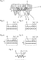
- Fig. 1 shows a portion of a tread forming molding with two profile webs 1, which are formed on the inside of the molding and form grooves in the tread during vulcanization.
- a slat plate 2 On the molded part inside a slat plate 2 is anchored between the two profile webs 1, which forms an incision in the tread during vulcanization.
- vent holes 3 are provided, which in the immediate vicinity of the lamellae 2 of the tread inside forming part inside running straight into the molding and open inside the molding in leading to the molding outside, preferably also designed as bores venting channels 4.
- the lamination sheet 2 are preferably at least three, in the in Fig. 1 variant shown five, provided in cross-section circular vent holes 3, each having a diameter d 1 of 0.05 mm to 0.15 mm, in particular of up to 0.08 mm.
- d 1 of 0.05 mm to 0.15 mm
- At the molding inside the vent holes 3 from the hole center to the fin plate 2 each have a normal distance or a distance determined as the minimum distance of 0.5 mm to 1.0 mm.
- the vent holes 3 are arranged along the molded part inside in a row and evenly distributed between the two profile webs 1, so that adjacent vent holes 3 on the molding inside preferably have substantially equal distances.
- the vent channels 4 have at least over the majority of their extension to a constant diameter d 2 of 3.0 mm to 5.0 mm, wherein in the in Fig. 1 shown embodiment in the area radially inside the lamella 2 two adjacent ventilation ducts 4 are provided.
- the two adjacent vent holes 3 extend substantially parallel to each other and at an acute angle into the molding into it and each lead together into one of the two further venting channels 4.
- vent holes 3 on the profile positive of the tread in the immediate vicinity of the cutting edges of the slits formed by the lamellae low, for example, about 0.1 mm to 0.2 mm high elevations 6 ( Fig. 2 to Fig. 6 ).
- five through-holes 5 are also formed in the lamination plate 2 directly at the inner side of the molding, which have a normal distance a 1 of at most 1.0 mm, determined in each case from the center of the through-hole 5, for the inner part of the molding.
- the through holes 5 are preferably located at the vent holes 3 and have a diameter d 3 of 0.3 mm to 1.0 mm.
- the through bores 5 contribute to more effective air removal.
- Fig. 2 to Fig. 6 show plan views of very simplified profile blocks shown, which belong to a tread that has been vulcanized in a vulcanization mold with vent holes 3 in lamella plates.
- 4 and FIG. 5 are variant embodiments of tread blocks in running direction bound LaustMail, so that the direction of unwinding of the tire is characterized by an arrow R when driving forward.
- the profile blocks in the Fig. 2 to 5 have two, each formed by a lamellae incisions 7 with a constant width of 0.3 mm to 0.8 mm, which in the illustrated simplified embodiments traverse the respective profile block and run straight and parallel to each other.
- the in Fig. 6 shown profile block has, for example, only a single, in plan view wavy incision 7 '.
- the incisions 7, 7 'extend in the variants shown in the transverse direction of the tread but they can also extend at an acute angle to the tread transverse direction and zigzag in plan view, staircase-shaped and the like designed.
- profile blocks shown are of vent holes, which are provided on both sides of the incisions 7 forming lamella plates in the molding, along each incision edge 7a, 7b five elevations 6 have been formed, which in Fig. 2 in pairs, separated by the respective incision 7, opposite each other.
- the elevations 6 running along the one incision edge 7a are offset in the transverse direction of the tread 6 relative to the elevations 6 running along the other incision edge 7b.
- each incision 7 due to the directionality of the tread each on entering the ground contact surface first forward, incoming incision edge 7a and an expiring incision edge 7b on.
- vent holes 3 which are formed only on one side of the incisions 7 forming lamella plates in the molding are in Fig. 4 along the outgoing cutting edge 7b, in Fig. 5
- five elevations 6 have been formed along the incoming incision edge 7a.
- trained surveys 6 an improvement of Snow traction and braking properties on ice
- Profile block shown with a wave-shaped incision 7 ' is formed in the region of the valleys of the waveform of the incision edges 7'a, 7'b provided at corresponding positions ventilation holes in the forming lamella each a survey 6.
- a certain equalization of the pressure takes place at the incision edges 7'a, 7'b, since the elevations 6 in the valleys of the waveform compensate for the lower contact pressure in the region of the valleys.
Landscapes
- Engineering & Computer Science (AREA)
- Mechanical Engineering (AREA)
- Moulds For Moulding Plastics Or The Like (AREA)
- Tires In General (AREA)
Abstract
Description
- Die Erfindung betrifft eine Vulkanisationsform für einen Fahrzeugluftreifen mit Formteilen, die den profilierten Laufstreifen des Reifens ausformen und im Laufstreifen Einschnitte bildende Lamellenbleche aufweisen, wobei an zumindest einer Seite und in unmittelbarer Nähe zumindest eines Lamellenbleches zumindest eine in den Formteil hinein verlaufende, im Querschnitt kreisförmige Entlüftungsbohrung ausgebildet ist.
- Die Erfindung betrifft ferner einen Fahrzeugluftreifen, welche in einer Vulkanisationsform gemäß der Erfindung vulkanisiert worden ist.
- Beim Einformen eines Reifenrohlings in eine Vulkanisationsform wird in der Vulkanisationsform vorhandene Luft zwischen dieser und dem Reifenrohling eingeschlossen und muss daher abgeführt werden. Zu diesem Zweck ist es üblich, in der Vulkanisationsform eine Vielzahl von Entlüftungsbohrungen mit einem Durchmesser von 3 mm bis 5 mm vorzusehen, welche ein Abführen der eingeschlossenen Luft gestatten. Die Entlüftungsbohrungen bilden bei der Vulkanisation kleine Erhebungen an der Oberfläche des Laufstreifens aus. Werden in den Entlüftungsbohrungen Entlüftungseinheiten mit Ventilen eingesetzt, die bei eingeformtem Reifenrohling die Entlüftungsbohrungen verschließen, wird das Ausbilden von ausgeprägten Erhebungen am Laufstreifen weitgehend verhindert.
- Eine Vulkanisationsform der eingangs genannten Art ist beispielsweise aus der
DE 10 2009 027 127 A1 bekannt. Am Fußpunkt von Rillen ausformenden Profilstegen sind beidseitig und unmittelbar bei zwischen den Profilstegen verlaufenden Lamellenblechen Entlüftungsbohrungen ausgebildet. An jeder Seite der Lamellenbleche sind jeweils zwei Entlüftungsbohrungen vorgesehen. In jeder Entlüftungsbohrung ist ein Entlüftungsstift eingebracht, sodass der Querschnitt der Entlüftungsbohrungen durch den Entlüftungsstift verengt ist. - Die im Laufstreifen durch Entlüftungsbohrungen gebildeten kleinen Erhebungen sind vor allem bei Reifen, die unter winterlichen Fahrbedingungen, also auf Eis oder Schnee, gefahren werden, nachteilig, da sie die Nettokontaktfläche des Laufstreifens reduzieren, über welche Reibung, insbesondere auf Eis, übertragen wird.
- Der Erfindung liegt daher die Aufgabe zugrunde, eine Vulkanisationsform der eingangs genannten Art derart zu gestalten, dass eine sichere Formentlüftung gewährleistet ist, wobei die Griffeigenschaften auf Schnee und/oder Eis bei neuem Reifen durch eine Reduktion der Fläche der Erhebungen, die von den Entlüftungsbohrungen stammen, verbessert sind.
- Die gestellte Aufgabe wird erfindungsgemäß dadurch gelöst, dass die Entlüftungsbohrung einen Durchmesser von 0,05 mm bis 0,15 mm aufweist.
- Vorzugsweise sind an zumindest einer Seite des Lamellenbleches mindestens zwei, insbesondere mindestens drei, Entlüftungsbohrungen ausgebildet.
- Gemäß der Erfindung ist daher in unmittelbarer Nähe sowie an zumindest einer Seite von Lamellenblechen zumindest eine Entlüftungsbohrung mit sehr kleinem Querschnitt im Formteil ausgebildet, welche die Entlüftung der Vulkanisationsform im heiklen Bereich des Lamellenbleches sicherstellt. Dadurch lässt sich gegenüber einer herkömmlichen Ausführung von Entlüftungsbohrungen die Gesamtfläche von durch Entlüftungsbohrungen ausgebildeten Erhebungen im Laufstreifen deutlich reduzieren. Die Entlüftungsbohrungen gemäß der Erfindung hinterlassen am Laufstreifen ausgesprochen kleine und niedrige Erhebungen, sodass die Nettokontaktfläche des Laufstreifens und damit die Winterfahreigenschaften bei neuem Reifen kaum beeinträchtigt werden.
- Für die Effektivität der gemäß der Erfindung vorgesehenen winzigen Entlüftungsbohrungen ist es von Vorteil, wenn diese möglichst nahe bei den Lamellenblechen positioniert sind. Es ist daher von Vorteil, wenn der als minimaler Abstand ermittelte Abstand zwischen dem Mittelpunkt der jeweiligen Entlüftungsbohrung und dem Lamellenblech 0,07 mm bis 1,0 mm beträgt.
- Die Entlüftungsbohrungen gemäß der Erfindung können in einer größeren Anzahl vorgesehen werden und weisen vor allem in diesem Fall vorzugsweise einen Durchmesser von bis zu 0,08 mm auf.
- Für eine gute Entlüftungswirkung ist es ferner günstig, wenn jede Entlüftungsbohrung in einen insbesondere ebenfalls als Bohrung ausgeführten Entlüftungskanal mündet, welcher eine wesentlich größere Querschnittsfläche als die Entlüftungsbohrung aufweist sowie vorzugsweise und über zumindest den Großteil seiner Erstreckung einen Durchmesser von 3,0 mm bis 5,0 mm aufweist.
- Bei einer bevorzugten Ausführungsform der Erfindung ist vorgesehen, dass jeweils eine größere Anzahl von Entlüftungsbohrungen an einer Seite des Lamellenbleches vorgesehen ist, wobei diese vorteilhafterweise im Wesentlichen gleich große Abstände zueinander aufweisen.
- Die Entlüftungswirkung der winzigen Entlüftungsbohrungen wird gemäß einer weiteren Ausführungsvariante der Erfindung dann unterstützt, wenn das Lamellenblech in unmittelbarer Nähe der Formsegmentinnenseite zumindest eine Durchgangsbohrung mit einem Durchmesser von 0,3 mm bis 1,0 mm aufweist. Dabei ist es vorteilhaft, wenn der Normalabstand des Mittelpunktes jeder Durchgangsbohrung von der Innenseite des Formteiles höchstens 1,5 mm beträgt und wenn das Lamellenblech bei jeder der winzigen Entlüftungsbohrungen mit einer Durchgangsbohrung versehen ist.
- Erfindungsgemäß ausgeführte Vulkanisationsformen weisen üblicherweise eine Vielzahl von Einschnitten im Laufstreifen ausformenden Lamellenblechen auf. Bei einer möglichen Ausführungsform ist dabei an jeder Seite dieser Lamellenbleche mindestens eine, vorzugsweise sind mehrere Entlüftungsbohrung(en) vorgesehen. Diese Ausführung wird vor allem bei nicht laufrichtungsgebundenen Laufstreifen gewählt. Ist eine Vulkanisationsform mit einer Vielzahl von Einschnitten ausformenden Lamellenblechen zum Ausformen von laufrichtungsgebundenen Laufstreifen vorgesehen, ist es vorteilhaft, wenn nur an einer Seite von Lamellenblechen, bei diesen Lamellenblechen jedoch an der gleichen Seite, jeweils mindestens eine Entlüftungsbohrung vorgesehen ist. Die im Laufstreifen dadurch gebildeten winzigen Erhebungen in der Nähe der ein- oder auslaufenden Einschnittkanten, je nach Ausführung, können nun bestimmte Winterfahreigenschaften positiv beeinflussen.
- Bei Vulkanisationsformen mit wellenförmig ausgestalteten Lamellenblechen, die in Draufsicht wellenförmig verlaufende Einschnitte im Laufstreifen ausformen, ist es vorteilhaft, Entlüftungsbohrungen im Bereich der Täler der Wellenform der Lamellenbleche auszubilden. Die derart im Laufstreifen des neuen Reifens vorhandenen winzigen Erhebungen bewirken bei einer Verformung der Profilpositive durch Traktions- oder Bremskräfte eine gewisse Vergleichmäßigung des Druckes im Bereich der Einschnittkante.
- Die Erfindung betrifft ferner einen Fahrzeugluftreifen, welcher einen profilierten Laufstreifen mit Einschnitten aufweist und in einer erfindungsgemäß ausgeführten Vulkanisationsform vulkanisiert worden ist. Ein derartiger Fahrzeugluftreifen weist bei zumindest einer Einschnittkante seiner Einschnitte zumindest eine im Wesentlichen kreisförmige Erhebung mit einem Durchmesser von 0,05 mm bis 0,15 mm und einer Höhe von 0,1 mm bis 0,2 mm auf. Diese winzigen Erhebungen haben bei neuem Reifen positive Auswirkungen auf die Winterfahreigenschaften, beispielsweise die Bremseigenschaften, ferner auf Schneetraktion und Eistraktion. Bei einem laufrichtungsgebunden gestalteten Laufstreifen können diese winzigen Erhebungen gezielt an einlaufenden oder auslaufenden Einschnittkanten ausgebildet sein, sodass die erwähnten Eigenschaften, ja nach der Position der Einschnitte am Laufstreifen, auf besonders wirksame Weise beeinflusst werden können.
- Weitere Merkmale, Vorteile und Einzelheiten der Erfindung werden nun anhand der Zeichnung, die schematisch Ausführungsbeispiele der Erfindung zeigt, näher beschrieben. Dabei zeigen
-
Fig. 1 einen vereinfachten Querschnitt durch einen Teilbereich eines Formteiles einer Vulkanisationsform für einen Fahrzeugluftreifen mit einer Ausführungsvariante der Erfindung und -
Fig. 2 bis Fig. 6 Draufsichten auf Profilblöcke eines Laufstreifens eines Fahrzeugluftreifens, welche in Vulkanisationsformen gemäß der Erfindung vulkanisiert worden sind. - Vulkanisationsformen für Fahrzeugluftreifen für PKW weisen üblicherweise Seitenwandschalen, welche die Seitenwände des Reifens ausformen, und sieben bis dreizehn den Laufstreifenbereich des Reifens formende Formteile auf. Zur Vulkanisation wird der fertig aufgebaute Reifenrohling in die Vulkanisationsform eingebracht und in diese in bekannter Weise eingeformt. Beim Einformen wird die zwischen der Vulkanisationsform und dem Reifenrohling eingeschlossene Luft durch Entlüftungseinrichtungen in der Vulkanisationsform abgeführt und der Reifenrohling anschließend vulkanisiert.
-
Fig. 1 zeigt einen Teilbereich eines den Laufstreifen formenden Formteiles mit zwei Profilstegen 1, welche an der Innenseite des Formteiles ausgebildet sind und bei der Vulkanisation Rillen im Laufstreifen formen. An der Formteilinnenseite ist zwischen den beiden Profilstegen 1 ein Lamellenblech 2 verankert, welches bei der Vulkanisation einen Einschnitt im Laufstreifen formt. - Zur Entlüftung der Vulkanisationsform im Bereich der Lamellenbleche 2 sind Entlüftungsbohrungen 3 vorgesehen, welche in unmittelbarer Nähe der Lamellenbleche 2 von der den Laufstreifen ausformenden Formteilinnenseite gerade in den Formteil hineinverlaufen und innerhalb des Formteiles in zur Formteilaußenseite führende, vorzugsweise ebenfalls als Bohrungen ausgeführte Entlüftungskanäle 4 einmünden. Entlang zumindest einer Seite des Lamellenbleches 2 sind vorzugsweise mindestens drei, bei der in
Fig. 1 gezeigten Variante fünf, im Querschnitt kreisförmige Entlüftungsbohrungen 3 vorgesehen, welche jeweils einen Durchmesser d1 von 0,05 mm bis 0,15 mm, insbesondere von bis zu 0,08 mm, aufweisen. An der Formteilinnenseite weisen die Entlüftungsbohrungen 3 vom Bohrungsmittelpunkt zum Lamellenblech 2 jeweils einen Normalabstand bzw. einen als Minimalabstand ermittelten Abstand von 0,5 mm bis 1,0 mm auf. Die Entlüftungsbohrungen 3 sind entlang der Formteilinnenseite in einer Reihe sowie gleichmäßig verteilt zwischen den beiden Profilstegen 1 angeordnet, sodass benachbarte Entlüftungsbohrungen 3 an der Formteilinnenseite vorzugsweise im Wesentlichen gleich große Abstände aufweisen. - Die Entlüftungskanäle 4 weisen zumindest über den Großteil ihrer Erstreckung einen konstanten Durchmesser d2 von 3,0 mm bis 5,0 mm auf, wobei bei der in
Fig. 1 gezeigten Ausführungsvariante im Bereich radial innerhalb des Lamellenbleches 2 drei nebeneinander verlaufende Entlüftungskanäle 4 vorgesehen sind. - Von den fünf in
Fig. 1 vorgesehenen Entlüftungsbohrungen 3 verläuft die mittlere Entlüftungsbohrung 3 im Wesentlichen senkrecht in den Formteil hinein und mündet in den mittleren Entlüftungskanal 4. Von den weiteren vier Entlüftungsbohrung 3 verlaufen die beiden jeweils nebeneinander liegenden Entlüftungsbohrungen 3 im Wesentlichen parallel zueinander sowie unter einem spitzen Winkel in den Formteil hinein und münden jeweils gemeinsam in einen der beiden weiteren Entlüftungskanäle 4. - Am fertigen Reifen hinterlassen die Entlüftungsbohrungen 3 auf den Profilpositiven des Laufstreifens in unmittelbarer Nähe der Einschnittkanten der von den Lamellenblechen gebildeten Einschnitte niedrige, beispielsweise etwa 0,1 mm bis 0,2 mm hohe Erhebungen 6 (
Fig. 2 bis Fig. 6 ). - Bei der in
Fig. 1 gezeigten Ausführung sind ferner im Lamellenblech 2 unmittelbar bei der Formteilinnenseite fünf Durchgangsbohrungen 5 ausgebildet, welche zur Formteilinnenseite einen jeweils vom Mittelpunkt der Durchgangsbohrung 5 ermittelten Normalabstand a1 von höchstens 1,0 mm aufweisen. Die Durchgangsbohrungen 5 befinden sich vorzugsweise bei den Entlüftungsbohrungen 3 und weisen einen Durchmesser d3 von 0,3 mm bis 1,0 mm auf. Insbesondere bei nur an einer Seite der Lamellenbleche 2 ausgebildeten Entlüftungsbohrungen 3 tragen die Durchgangsbohrungen 5 zu einer effektiveren Luftabfuhr bei. -
Fig. 2 bis Fig. 6 zeigen Draufsichten auf sehr vereinfacht dargestellte Profilblöcke, welche zu einem Laufstreifen gehören, der in einer Vulkanisationsform mit Entlüftungsbohrungen 3 bei Lamellenblechen vulkanisiert worden ist.Fig. 4 und Fig. 5 sind Ausführungsvarianten von Profilblöcken in laufrichtungsgebunden ausgeführten Laustreifen, sodass die Abrollrichtung des Reifens bei Vorwärtsfahrt durch einen Pfeil R gekennzeichnet ist. Die Profilblöcke in denFig. 2 bis 5 weisen zwei, jeweils von einem Lamellenblech gebildete Einschnitte 7 mit einer konstanten Breite von 0,3 mm bis 0,8 mm auf, die bei den dargestellten vereinfachten Ausführungen den jeweiligen Profilblock durchqueren sowie gerade und parallel zueinander verlaufen. Der inFig. 6 gezeigte Profilblock weist beispielhaft nur einen einzigen, in Draufsicht wellenförmigen Einschnitt 7' auf. Die Einschnitte 7, 7' erstrecken sich bei den gezeigten Varianten in Querrichtung des Laufstreifens, sie können sich jedoch auch unter spitzen Winkel zur Laufstreifenquerrichtung verlaufen und in Draufsicht zickzackförmig, treppenförmig und dergleichen gestaltet sein. - Bei den in
Fig. 2 und Fig. 3 gezeigten Profilblöcken sind von Entlüftungsbohrungen, die beidseitig der die Einschnitte 7 ausformenden Lamellenbleche im Formteil vorgesehen sind, entlang jeder Einschnittkante 7a, 7b jeweils fünf Erhebungen 6 ausgebildet worden, welche inFig. 2 einander paarweise, durch den jeweiligen Einschnitt 7 getrennt, gegenüberliegen. Bei der inFig. 3 gezeigten Variante sind die entlang der einen Einschnittkante 7a verlaufenden Erhebungen 6 gegenüber den entlang der anderen Einschnittkante 7b verlaufenden Erhebungen 6 in Laufstreifenquerrichtung versetzt. - Bei den in
Fig. 4 und Fig. 5 gezeigten Profilblöcken weist jeder Einschnitt 7 infolge der Laufrichtungsgebundenheit des Laufstreifens jeweils eine bei Vorwärtsfahrt zuerst in die Bodenaufstandsfläche eintretende, einlaufende Einschnittkante 7a sowie eine auslaufende Einschnittkante 7b auf. Von Entlüftungsbohrungen 3, die nur an einer Seite der die Einschnitte 7 ausformenden Lamellenbleche im Formteil ausgebildet sind, sind inFig. 4 entlang der auslaufenden Einschnittkante 7b, inFig. 5 entlang der einlaufenden Einschnittkante 7a beispielhaft jeweils fünf Erhebungen 6 ausgebildet worden. Bei neuem Reifen bewirken gemäßFig. 4 ausgebildete Erhebungen 6 eine Verbesserung der Schneetraktion und der Bremseigenschaften auf Eis, gemäßFig. 5 ausgebildete Erhebungen 6 eine Verbesserung der Eistraktion und der Bremseigenschaften auf Schnee. - Bei dem in
Fig. 6 gezeigte Profilblock mit einem wellenförmigen Einschnitt 7' ist im Bereich der Täler der Wellenform der Einschnittkanten 7'a, 7'b durch an entsprechenden Positionen vorgesehene Entlüftungsbohrungen beim formenden Lamellenblech jeweils eine Erhebung 6 ausgebildet. Bei einer Verformung des Profilblockes durch Traktions- oder Bremskräfte findet eine gewisse Vergleichmäßigung des Druckes bei den Einschnittkanten 7'a, 7'b statt, da die Erhebungen 6 bei den Tälern der Wellenform den geringeren Anpressdruck im Bereich der Täler ausgleichen. -
- 1
- Profilsteg
- 2
- Lamellenblech
- 3
- Entlüftungsbohrung
- 4
- Entlüftungskanal
- 5
- Durchgangsbohrung
- 6
- Erhebung
- 7, 7'
- Einschnitt
- 7a, 7'a'
- auslaufende Einschnittkante
- 7b, 7'b
- einlaufende Einschnittkante
- a1
- Abstand
- d1, d2, d3
- Durchmesser
- R
- Abrollrichtung
Claims (14)
- Vulkanisationsform für einen Fahrzeugluftreifen mit Formteilen, die den profilierten Laufstreifen des Reifens ausformen und im Laufstreifen Einschnitte (7, 7') bildende Lamellenbleche (2) aufweisen, wobei an zumindest einer Seite und in unmittelbarer Nähe zumindest eines Lamellenbleches (2) zumindest eine in den Formteil hinein verlaufende, im Querschnitt kreisförmige Entlüftungsbohrung (3) ausgebildet ist,
dadurch gekennzeichnet,
dass die Entlüftungsbohrung (3) einen Durchmesser (d1) von 0,05 mm bis 0,15 mm aufweist. - Vulkanisationsform nach Anspruch 1, dadurch gekennzeichnet, dass der als minimaler Abstand ermittelte Abstand zwischen dem Mittelpunkt der Entlüftungsbohrung (3) und dem Lamellenblech (2) 0,07 mm bis 1,0 mm beträgt.
- Vulkanisationsform nach Anspruch 1 oder 2, dadurch gekennzeichnet, dass der Durchmesser (d1) der Entlüftungsbohrung (3) bis zu 0,08 mm beträgt.
- Vulkanisationsform nach einem der Ansprüche 1 bis 3, dadurch gekennzeichnet,
dass an zumindest einer Seite des Lamellenbleches (2) mindestens zwei, insbesondere mindestens drei, Entlüftungsbohrungen (3) ausgebildet sind. - Vulkanisationsform nach einem der Ansprüche 1 bis 4, dadurch gekennzeichnet,
dass jede Entlüftungsbohrung (3) in einen insbesondere ebenfalls als Bohrung ausgeführten Entlüftungskanal (4, 4') mündet, welcher eine wesentlich größere Querschnittsfläche als die Entlüftungsbohrung sowie vorzugsweise und zumindest über den Großteil seiner Erstreckung einen Durchmesser (d2) von 3,0 mm bis 5,0 mm aufweist. - Vulkanisationsform nach einem der Ansprüche 1 bis 5, dadurch gekennzeichnet,
dass die an einer Seite des Lamellenbleches (2) vorgesehen Entlüftungsbohrungen (3) im Wesentlichen gleich große Abstände (a2) zueinander aufweisen. - Vulkanisationsform nach einem der Ansprüche 1 bis 6, dadurch gekennzeichnet,
dass das Lamellenblech (2) in unmittelbarer Nähe der Formsegmentinnenseite zumindest eine Durchgangsbohrung (5) mit einem Durchmesser (d3) von 0,3 mm bis 1,0 mm aufweist. - Vulkanisationsform nach Anspruch 7, dadurch gekennzeichnet, dass der Normalabstand (a1) des Mittelpunktes der Durchgangsbohrung (5) von der Innenseite des Formteiles höchstens 1,5 mm beträgt.
- Vulkanisationsform nach Anspruch 7 oder 8, dadurch gekennzeichnet, dass das Lamellenblech (2) bei jeder Entlüftungsbohrung (3) eine Durchgangsbohrung (5) aufweist.
- Vulkanisationsform nach einem der Ansprüche 1 bis 9, mit einer Vielzahl von Einschnitte im Laustreifen ausformenden Lamellenblechen, dadurch gekennzeichnet, dass an jeder Seite der Lamellenbleche mindestens eine Entlüftungsbohrung (3) vorgesehen ist.
- Vulkanisationsform nach einem der Ansprüche 1 bis 9, welche einen Fahrzeugluftreifen mit einem laufrichtungsgebundenen Laufstreifen formt und mit einer Vielzahl von Einschnitte ausformenden Lamellenblechen versehen ist, dadurch gekennzeichnet, dass Lamellenbleche vorgesehen sind, bei welchen nur an ihrer einen Seite, und zwar an der gleichen Seite, jeweils mindestens eine Entlüftungsbohrung (3) vorgesehen ist.
- Vulkanisationsform nach Anspruch 10 oder 11, mit wellenförmig ausgestalteten Lamellenblechen, dadurch gekennzeichnet, dass die Entlüftungsbohrungen (3) im Bereich der Täler der Wellenform ausgebildet sind.
- Fahrzeugluftreifen, welcher einen profilierten Laufstreifen mit Einschnitten (7, 7') aufweist und in einer Vulkanisationsform gemäß einem der Ansprüche 1 bis 12 vulkanisiert worden ist, dadurch gekennzeichnet, dass bei zumindest einer Einschnittkante (7a, 7'a, 7b, 7'b) der Einschnitte (7, 7') zumindest eine im Wesentlichen kreisförmige Erhebung (6) mit einem Durchmesser von 0,05 mm bis 0,15 mm und einer Höhe von 0,1 mm bis 0,2 mm ausgebildet ist.
- Fahrzeugluftreifen nach Ansprüche 13, mit einem laufrichtungsgebunden gestalteten Laufstreifen, dadurch gekennzeichnet, dass Einschnitte (7) vorhanden sind, bei welchen entweder nur entlang der einlaufenden oder nur entlang der auslaufenden Einschnittkante (7a, 7b) zumindest eine Erhebung (6) ausgebildet ist.
Applications Claiming Priority (1)
| Application Number | Priority Date | Filing Date | Title |
|---|---|---|---|
| DE102016213332.2A DE102016213332A1 (de) | 2016-07-21 | 2016-07-21 | Vulkanisationsform und Fahrzeugluftreifen |
Publications (2)
| Publication Number | Publication Date |
|---|---|
| EP3272509A1 true EP3272509A1 (de) | 2018-01-24 |
| EP3272509B1 EP3272509B1 (de) | 2021-02-24 |
Family
ID=58715088
Family Applications (1)
| Application Number | Title | Priority Date | Filing Date |
|---|---|---|---|
| EP17171643.4A Active EP3272509B1 (de) | 2016-07-21 | 2017-05-18 | Vulkanisationsform und fahrzeugluftreifen |
Country Status (2)
| Country | Link |
|---|---|
| EP (1) | EP3272509B1 (de) |
| DE (1) | DE102016213332A1 (de) |
Families Citing this family (1)
| Publication number | Priority date | Publication date | Assignee | Title |
|---|---|---|---|---|
| DE102018205607A1 (de) | 2018-04-13 | 2019-10-17 | Continental Reifen Deutschland Gmbh | Vulkanisationsform |
Citations (8)
| Publication number | Priority date | Publication date | Assignee | Title |
|---|---|---|---|---|
| DE102009027127B3 (de) | 2009-06-23 | 2010-12-30 | BSH Bosch und Siemens Hausgeräte GmbH | Automatische gesteuerte Waschmaschine mit einer Waschmitteleinspüleinrichtung |
| DE102009017127A1 (de) * | 2009-04-15 | 2011-01-27 | Continental Reifen Deutschland Gmbh | Element einer Vulkanisierform, eine Vulkanisierform sowie ein Verfahren zur Herstellung eines Elementes einer Vulkanisierform |
| DE102010016906A1 (de) * | 2010-05-11 | 2011-11-17 | Continental Reifen Deutschland Gmbh | Fahrzeugluftreifen mit einem Laufstreifen |
| DE102011055662A1 (de) * | 2011-11-24 | 2013-05-29 | Continental Reifen Deutschland Gmbh | Vulkanisierform für Fahrzeugreifen |
| EP2689920A1 (de) * | 2012-07-26 | 2014-01-29 | Continental Reifen Deutschland GmbH | Verfahren und Vorrichtung zur Unterstützung des Entformens eines vulkanisierten Fahrzeugluftreifens |
| DE102013225298A1 (de) * | 2013-12-09 | 2015-06-11 | Continental Reifen Deutschland Gmbh | Vulkanisationsform und Fahrzeugluftreifen |
| DE102014216868A1 (de) * | 2014-08-25 | 2016-02-25 | Continental Reifen Deutschland Gmbh | Vulkanisationswerkzeug |
| WO2016109037A1 (en) * | 2014-12-31 | 2016-07-07 | Bridgestone Americas Tire Operations, Llc | Sipe blade venting structure |
-
2016
- 2016-07-21 DE DE102016213332.2A patent/DE102016213332A1/de not_active Withdrawn
-
2017
- 2017-05-18 EP EP17171643.4A patent/EP3272509B1/de active Active
Patent Citations (8)
| Publication number | Priority date | Publication date | Assignee | Title |
|---|---|---|---|---|
| DE102009017127A1 (de) * | 2009-04-15 | 2011-01-27 | Continental Reifen Deutschland Gmbh | Element einer Vulkanisierform, eine Vulkanisierform sowie ein Verfahren zur Herstellung eines Elementes einer Vulkanisierform |
| DE102009027127B3 (de) | 2009-06-23 | 2010-12-30 | BSH Bosch und Siemens Hausgeräte GmbH | Automatische gesteuerte Waschmaschine mit einer Waschmitteleinspüleinrichtung |
| DE102010016906A1 (de) * | 2010-05-11 | 2011-11-17 | Continental Reifen Deutschland Gmbh | Fahrzeugluftreifen mit einem Laufstreifen |
| DE102011055662A1 (de) * | 2011-11-24 | 2013-05-29 | Continental Reifen Deutschland Gmbh | Vulkanisierform für Fahrzeugreifen |
| EP2689920A1 (de) * | 2012-07-26 | 2014-01-29 | Continental Reifen Deutschland GmbH | Verfahren und Vorrichtung zur Unterstützung des Entformens eines vulkanisierten Fahrzeugluftreifens |
| DE102013225298A1 (de) * | 2013-12-09 | 2015-06-11 | Continental Reifen Deutschland Gmbh | Vulkanisationsform und Fahrzeugluftreifen |
| DE102014216868A1 (de) * | 2014-08-25 | 2016-02-25 | Continental Reifen Deutschland Gmbh | Vulkanisationswerkzeug |
| WO2016109037A1 (en) * | 2014-12-31 | 2016-07-07 | Bridgestone Americas Tire Operations, Llc | Sipe blade venting structure |
Also Published As
| Publication number | Publication date |
|---|---|
| DE102016213332A1 (de) | 2018-01-25 |
| EP3272509B1 (de) | 2021-02-24 |
Similar Documents
| Publication | Publication Date | Title |
|---|---|---|
| EP3079875B1 (de) | Vulkanisationsform | |
| EP3152067B1 (de) | Fahrzeugluftreifen | |
| EP2070731B1 (de) | Fahrzeugluftreifen | |
| EP2965925B1 (de) | Fahrzeugluftreifen | |
| DE102010000272A1 (de) | Fahrzeugluftreifen | |
| WO2019001789A1 (de) | Fahrzeugluftreifen | |
| WO2016128087A1 (de) | Selektives-laser-melting (slm) hergestellte lamelle | |
| DE102016202655A1 (de) | Fahrzeugluftreifen | |
| WO2019001790A1 (de) | Fahrzeugluftreifen | |
| DE102019211027A1 (de) | Fahrzeugluftreifen | |
| EP3019346A1 (de) | Laufstreifenprofil eines fahrzeugluftreifens | |
| DE102010016906A1 (de) | Fahrzeugluftreifen mit einem Laufstreifen | |
| EP3321077B1 (de) | Vulkanisationsform und fahrzeugluftreifen | |
| EP3554855B1 (de) | Fahrzeugluftreifen | |
| EP3659825B1 (de) | Fahrzeugluftreifen | |
| DE102014214841A1 (de) | Vulkanisationsform zum Vulkanisieren eines Fahrzeugluftreifens und Fahrzeugluftreifen | |
| EP3321078A1 (de) | Vulkanisationsform und fahrzeugluftreifen | |
| EP3130481A1 (de) | Fahrzeugluftreifen | |
| EP3272509B1 (de) | Vulkanisationsform und fahrzeugluftreifen | |
| EP2217456B1 (de) | Fahrzeugluftreifen | |
| EP3890995B1 (de) | Fahrzeugluftreifen | |
| WO2018103920A1 (de) | Fahrzeugluftreifen | |
| WO2022253375A1 (de) | Fahrzeugluftreifen | |
| EP1667852B1 (de) | Fahrzeugluftreifen | |
| EP3715148B1 (de) | Fahrzeugluftreifen |
Legal Events
| Date | Code | Title | Description |
|---|---|---|---|
| PUAI | Public reference made under article 153(3) epc to a published international application that has entered the european phase |
Free format text: ORIGINAL CODE: 0009012 |
|
| STAA | Information on the status of an ep patent application or granted ep patent |
Free format text: STATUS: THE APPLICATION HAS BEEN PUBLISHED |
|
| AK | Designated contracting states |
Kind code of ref document: A1 Designated state(s): AL AT BE BG CH CY CZ DE DK EE ES FI FR GB GR HR HU IE IS IT LI LT LU LV MC MK MT NL NO PL PT RO RS SE SI SK SM TR |
|
| AX | Request for extension of the european patent |
Extension state: BA ME |
|
| STAA | Information on the status of an ep patent application or granted ep patent |
Free format text: STATUS: REQUEST FOR EXAMINATION WAS MADE |
|
| 17P | Request for examination filed |
Effective date: 20180724 |
|
| RBV | Designated contracting states (corrected) |
Designated state(s): AL AT BE BG CH CY CZ DE DK EE ES FI FR GB GR HR HU IE IS IT LI LT LU LV MC MK MT NL NO PL PT RO RS SE SI SK SM TR |
|
| GRAP | Despatch of communication of intention to grant a patent |
Free format text: ORIGINAL CODE: EPIDOSNIGR1 |
|
| STAA | Information on the status of an ep patent application or granted ep patent |
Free format text: STATUS: GRANT OF PATENT IS INTENDED |
|
| INTG | Intention to grant announced |
Effective date: 20201105 |
|
| RAP1 | Party data changed (applicant data changed or rights of an application transferred) |
Owner name: CONTINENTAL REIFEN DEUTSCHLAND GMBH |
|
| GRAS | Grant fee paid |
Free format text: ORIGINAL CODE: EPIDOSNIGR3 |
|
| GRAA | (expected) grant |
Free format text: ORIGINAL CODE: 0009210 |
|
| STAA | Information on the status of an ep patent application or granted ep patent |
Free format text: STATUS: THE PATENT HAS BEEN GRANTED |
|
| AK | Designated contracting states |
Kind code of ref document: B1 Designated state(s): AL AT BE BG CH CY CZ DE DK EE ES FI FR GB GR HR HU IE IS IT LI LT LU LV MC MK MT NL NO PL PT RO RS SE SI SK SM TR |
|
| REG | Reference to a national code |
Ref country code: CH Ref legal event code: EP |
|
| REG | Reference to a national code |
Ref country code: DE Ref legal event code: R096 Ref document number: 502017009434 Country of ref document: DE |
|
| REG | Reference to a national code |
Ref country code: AT Ref legal event code: REF Ref document number: 1363922 Country of ref document: AT Kind code of ref document: T Effective date: 20210315 |
|
| REG | Reference to a national code |
Ref country code: IE Ref legal event code: FG4D Free format text: LANGUAGE OF EP DOCUMENT: GERMAN |
|
| REG | Reference to a national code |
Ref country code: FI Ref legal event code: FGE |
|
| REG | Reference to a national code |
Ref country code: SE Ref legal event code: TRGR |
|
| REG | Reference to a national code |
Ref country code: LT Ref legal event code: MG9D |
|
| REG | Reference to a national code |
Ref country code: NL Ref legal event code: MP Effective date: 20210224 |
|
| PG25 | Lapsed in a contracting state [announced via postgrant information from national office to epo] |
Ref country code: GR Free format text: LAPSE BECAUSE OF FAILURE TO SUBMIT A TRANSLATION OF THE DESCRIPTION OR TO PAY THE FEE WITHIN THE PRESCRIBED TIME-LIMIT Effective date: 20210525 Ref country code: HR Free format text: LAPSE BECAUSE OF FAILURE TO SUBMIT A TRANSLATION OF THE DESCRIPTION OR TO PAY THE FEE WITHIN THE PRESCRIBED TIME-LIMIT Effective date: 20210224 Ref country code: NO Free format text: LAPSE BECAUSE OF FAILURE TO SUBMIT A TRANSLATION OF THE DESCRIPTION OR TO PAY THE FEE WITHIN THE PRESCRIBED TIME-LIMIT Effective date: 20210524 Ref country code: PT Free format text: LAPSE BECAUSE OF FAILURE TO SUBMIT A TRANSLATION OF THE DESCRIPTION OR TO PAY THE FEE WITHIN THE PRESCRIBED TIME-LIMIT Effective date: 20210624 Ref country code: BG Free format text: LAPSE BECAUSE OF FAILURE TO SUBMIT A TRANSLATION OF THE DESCRIPTION OR TO PAY THE FEE WITHIN THE PRESCRIBED TIME-LIMIT Effective date: 20210524 Ref country code: LT Free format text: LAPSE BECAUSE OF FAILURE TO SUBMIT A TRANSLATION OF THE DESCRIPTION OR TO PAY THE FEE WITHIN THE PRESCRIBED TIME-LIMIT Effective date: 20210224 |
|
| PG25 | Lapsed in a contracting state [announced via postgrant information from national office to epo] |
Ref country code: PL Free format text: LAPSE BECAUSE OF FAILURE TO SUBMIT A TRANSLATION OF THE DESCRIPTION OR TO PAY THE FEE WITHIN THE PRESCRIBED TIME-LIMIT Effective date: 20210224 Ref country code: RS Free format text: LAPSE BECAUSE OF FAILURE TO SUBMIT A TRANSLATION OF THE DESCRIPTION OR TO PAY THE FEE WITHIN THE PRESCRIBED TIME-LIMIT Effective date: 20210224 Ref country code: NL Free format text: LAPSE BECAUSE OF FAILURE TO SUBMIT A TRANSLATION OF THE DESCRIPTION OR TO PAY THE FEE WITHIN THE PRESCRIBED TIME-LIMIT Effective date: 20210224 Ref country code: LV Free format text: LAPSE BECAUSE OF FAILURE TO SUBMIT A TRANSLATION OF THE DESCRIPTION OR TO PAY THE FEE WITHIN THE PRESCRIBED TIME-LIMIT Effective date: 20210224 |
|
| PG25 | Lapsed in a contracting state [announced via postgrant information from national office to epo] |
Ref country code: IS Free format text: LAPSE BECAUSE OF FAILURE TO SUBMIT A TRANSLATION OF THE DESCRIPTION OR TO PAY THE FEE WITHIN THE PRESCRIBED TIME-LIMIT Effective date: 20210624 |
|
| PG25 | Lapsed in a contracting state [announced via postgrant information from national office to epo] |
Ref country code: SM Free format text: LAPSE BECAUSE OF FAILURE TO SUBMIT A TRANSLATION OF THE DESCRIPTION OR TO PAY THE FEE WITHIN THE PRESCRIBED TIME-LIMIT Effective date: 20210224 Ref country code: EE Free format text: LAPSE BECAUSE OF FAILURE TO SUBMIT A TRANSLATION OF THE DESCRIPTION OR TO PAY THE FEE WITHIN THE PRESCRIBED TIME-LIMIT Effective date: 20210224 Ref country code: CZ Free format text: LAPSE BECAUSE OF FAILURE TO SUBMIT A TRANSLATION OF THE DESCRIPTION OR TO PAY THE FEE WITHIN THE PRESCRIBED TIME-LIMIT Effective date: 20210224 |
|
| REG | Reference to a national code |
Ref country code: DE Ref legal event code: R097 Ref document number: 502017009434 Country of ref document: DE |
|
| PG25 | Lapsed in a contracting state [announced via postgrant information from national office to epo] |
Ref country code: SK Free format text: LAPSE BECAUSE OF FAILURE TO SUBMIT A TRANSLATION OF THE DESCRIPTION OR TO PAY THE FEE WITHIN THE PRESCRIBED TIME-LIMIT Effective date: 20210224 Ref country code: RO Free format text: LAPSE BECAUSE OF FAILURE TO SUBMIT A TRANSLATION OF THE DESCRIPTION OR TO PAY THE FEE WITHIN THE PRESCRIBED TIME-LIMIT Effective date: 20210224 Ref country code: DK Free format text: LAPSE BECAUSE OF FAILURE TO SUBMIT A TRANSLATION OF THE DESCRIPTION OR TO PAY THE FEE WITHIN THE PRESCRIBED TIME-LIMIT Effective date: 20210224 |
|
| REG | Reference to a national code |
Ref country code: CH Ref legal event code: PL |
|
| PLBE | No opposition filed within time limit |
Free format text: ORIGINAL CODE: 0009261 |
|
| STAA | Information on the status of an ep patent application or granted ep patent |
Free format text: STATUS: NO OPPOSITION FILED WITHIN TIME LIMIT |
|
| GBPC | Gb: european patent ceased through non-payment of renewal fee |
Effective date: 20210524 |
|
| PG25 | Lapsed in a contracting state [announced via postgrant information from national office to epo] |
Ref country code: ES Free format text: LAPSE BECAUSE OF FAILURE TO SUBMIT A TRANSLATION OF THE DESCRIPTION OR TO PAY THE FEE WITHIN THE PRESCRIBED TIME-LIMIT Effective date: 20210224 Ref country code: AL Free format text: LAPSE BECAUSE OF FAILURE TO SUBMIT A TRANSLATION OF THE DESCRIPTION OR TO PAY THE FEE WITHIN THE PRESCRIBED TIME-LIMIT Effective date: 20210224 Ref country code: CH Free format text: LAPSE BECAUSE OF NON-PAYMENT OF DUE FEES Effective date: 20210531 Ref country code: LI Free format text: LAPSE BECAUSE OF NON-PAYMENT OF DUE FEES Effective date: 20210531 Ref country code: LU Free format text: LAPSE BECAUSE OF NON-PAYMENT OF DUE FEES Effective date: 20210518 Ref country code: MC Free format text: LAPSE BECAUSE OF FAILURE TO SUBMIT A TRANSLATION OF THE DESCRIPTION OR TO PAY THE FEE WITHIN THE PRESCRIBED TIME-LIMIT Effective date: 20210224 |
|
| 26N | No opposition filed |
Effective date: 20211125 |
|
| REG | Reference to a national code |
Ref country code: BE Ref legal event code: MM Effective date: 20210531 |
|
| PG25 | Lapsed in a contracting state [announced via postgrant information from national office to epo] |
Ref country code: SI Free format text: LAPSE BECAUSE OF FAILURE TO SUBMIT A TRANSLATION OF THE DESCRIPTION OR TO PAY THE FEE WITHIN THE PRESCRIBED TIME-LIMIT Effective date: 20210224 |
|
| PG25 | Lapsed in a contracting state [announced via postgrant information from national office to epo] |
Ref country code: IT Free format text: LAPSE BECAUSE OF FAILURE TO SUBMIT A TRANSLATION OF THE DESCRIPTION OR TO PAY THE FEE WITHIN THE PRESCRIBED TIME-LIMIT Effective date: 20210224 Ref country code: IE Free format text: LAPSE BECAUSE OF NON-PAYMENT OF DUE FEES Effective date: 20210518 Ref country code: GB Free format text: LAPSE BECAUSE OF NON-PAYMENT OF DUE FEES Effective date: 20210524 |
|
| PG25 | Lapsed in a contracting state [announced via postgrant information from national office to epo] |
Ref country code: IS Free format text: LAPSE BECAUSE OF FAILURE TO SUBMIT A TRANSLATION OF THE DESCRIPTION OR TO PAY THE FEE WITHIN THE PRESCRIBED TIME-LIMIT Effective date: 20210624 Ref country code: FR Free format text: LAPSE BECAUSE OF NON-PAYMENT OF DUE FEES Effective date: 20210531 |
|
| PG25 | Lapsed in a contracting state [announced via postgrant information from national office to epo] |
Ref country code: BE Free format text: LAPSE BECAUSE OF NON-PAYMENT OF DUE FEES Effective date: 20210531 |
|
| PG25 | Lapsed in a contracting state [announced via postgrant information from national office to epo] |
Ref country code: HU Free format text: LAPSE BECAUSE OF FAILURE TO SUBMIT A TRANSLATION OF THE DESCRIPTION OR TO PAY THE FEE WITHIN THE PRESCRIBED TIME-LIMIT; INVALID AB INITIO Effective date: 20170518 |
|
| PG25 | Lapsed in a contracting state [announced via postgrant information from national office to epo] |
Ref country code: CY Free format text: LAPSE BECAUSE OF FAILURE TO SUBMIT A TRANSLATION OF THE DESCRIPTION OR TO PAY THE FEE WITHIN THE PRESCRIBED TIME-LIMIT Effective date: 20210224 |
|
| REG | Reference to a national code |
Ref country code: AT Ref legal event code: MM01 Ref document number: 1363922 Country of ref document: AT Kind code of ref document: T Effective date: 20220518 |
|
| PG25 | Lapsed in a contracting state [announced via postgrant information from national office to epo] |
Ref country code: AT Free format text: LAPSE BECAUSE OF NON-PAYMENT OF DUE FEES Effective date: 20220518 |
|
| REG | Reference to a national code |
Ref country code: DE Ref legal event code: R081 Ref document number: 502017009434 Country of ref document: DE Owner name: CONTINENTAL REIFEN DEUTSCHLAND GMBH, DE Free format text: FORMER OWNER: CONTINENTAL REIFEN DEUTSCHLAND GMBH, 30165 HANNOVER, DE |
|
| PG25 | Lapsed in a contracting state [announced via postgrant information from national office to epo] |
Ref country code: MK Free format text: LAPSE BECAUSE OF FAILURE TO SUBMIT A TRANSLATION OF THE DESCRIPTION OR TO PAY THE FEE WITHIN THE PRESCRIBED TIME-LIMIT Effective date: 20210224 |
|
| PG25 | Lapsed in a contracting state [announced via postgrant information from national office to epo] |
Ref country code: TR Free format text: LAPSE BECAUSE OF FAILURE TO SUBMIT A TRANSLATION OF THE DESCRIPTION OR TO PAY THE FEE WITHIN THE PRESCRIBED TIME-LIMIT Effective date: 20210224 |
|
| PGFP | Annual fee paid to national office [announced via postgrant information from national office to epo] |
Ref country code: FI Payment date: 20240527 Year of fee payment: 8 |
|
| PGFP | Annual fee paid to national office [announced via postgrant information from national office to epo] |
Ref country code: SE Payment date: 20240521 Year of fee payment: 8 |
|
| PG25 | Lapsed in a contracting state [announced via postgrant information from national office to epo] |
Ref country code: MT Free format text: LAPSE BECAUSE OF FAILURE TO SUBMIT A TRANSLATION OF THE DESCRIPTION OR TO PAY THE FEE WITHIN THE PRESCRIBED TIME-LIMIT Effective date: 20210224 |
|
| PGFP | Annual fee paid to national office [announced via postgrant information from national office to epo] |
Ref country code: DE Payment date: 20250531 Year of fee payment: 9 |
|
| PG25 | Lapsed in a contracting state [announced via postgrant information from national office to epo] |
Ref country code: FI Free format text: LAPSE BECAUSE OF NON-PAYMENT OF DUE FEES Effective date: 20250518 |
|
| PG25 | Lapsed in a contracting state [announced via postgrant information from national office to epo] |
Ref country code: SE Free format text: LAPSE BECAUSE OF NON-PAYMENT OF DUE FEES Effective date: 20250519 |
|
| REG | Reference to a national code |
Ref country code: SE Ref legal event code: EUG |