EP3272464A1 - Push-on support member for fastening tools - Google Patents
Push-on support member for fastening tools Download PDFInfo
- Publication number
- EP3272464A1 EP3272464A1 EP17177702.2A EP17177702A EP3272464A1 EP 3272464 A1 EP3272464 A1 EP 3272464A1 EP 17177702 A EP17177702 A EP 17177702A EP 3272464 A1 EP3272464 A1 EP 3272464A1
- Authority
- EP
- European Patent Office
- Prior art keywords
- fastening tool
- support foot
- tracks
- support
- support member
- Prior art date
- Legal status (The legal status is an assumption and is not a legal conclusion. Google has not performed a legal analysis and makes no representation as to the accuracy of the status listed.)
- Granted
Links
Images







Classifications
-
- B—PERFORMING OPERATIONS; TRANSPORTING
- B25—HAND TOOLS; PORTABLE POWER-DRIVEN TOOLS; MANIPULATORS
- B25C—HAND-HELD NAILING OR STAPLING TOOLS; MANUALLY OPERATED PORTABLE STAPLING TOOLS
- B25C7/00—Accessories for nailing or stapling tools, e.g. supports
-
- B—PERFORMING OPERATIONS; TRANSPORTING
- B25—HAND TOOLS; PORTABLE POWER-DRIVEN TOOLS; MANIPULATORS
- B25C—HAND-HELD NAILING OR STAPLING TOOLS; MANUALLY OPERATED PORTABLE STAPLING TOOLS
- B25C1/00—Hand-held nailing tools; Nail feeding devices
- B25C1/06—Hand-held nailing tools; Nail feeding devices operated by electric power
Definitions
- This specification relates to fastening tools, and more particularly to fastening tools having support elements to orient the fastening tools to a work surface.
- the operator need only move the support foot toward the fastening tool until an upper surface of the support foot engages a lower surface of the fastening tool. Then the operator moves the support foot along the lower surface of the fastening tool until the leading edges of the support foot proximate open ends of the channels engage the tracks. The operator then slides the support foot along the tracks until the leading edges are deflected away from respective male detents on the tracks. The operator continues to push the support foot along the tracks until the male detents become nested in the female detents. The support foot is thus releasably but securely retained at the location of the male detents, having never required the use of any tools during the entire process. (It should be noted that in this respect, if desired, the tracks can be constructed of a plastic material so that they deflect away from the leading edge of the support foot, rather than vice-versa.)
- the operator need only push the support foot in the reverse direction along the tracks so that the respective detents separate, and until the support foot channels clear the tracks. Then, again without using any tools, the operator simply moves the support foot away from the fastening tool lower surface.
- the support foot and fastening tool provide a fail-safe method for preventing the support foot from being attached to the fastening tool backwards, namely at an orientation other than the desired orientation of the support foot relative to the fastening tool.
- the channels or slots provided in the upper surface of the support foot define respective open and closed ends. If an operator moves the support foot oriented backwards so that it engages the lower surface of the fastening tool, and then attempts to engage the tracks with the support member, the closed end of the support member blocks any further movement along the lower surface of the fastening tool.
- the only way the support member can be attached to the tracks disposed on the fastening tool is by orienting the support member correctly relative to the fastening tool.
- the underside of the fastening tool or of the magazine, as the case may be is provided with a plurality of detents on each track, corresponding to a plurality of locations along the track at which it is desired to retain the support member.
- yet another feature of the support member and fastening tool allows an operator, without using any tools, to compensate for changes in height of the contact trip occasioned by using an adjustable contact trip mechanism. If, for example, the contact trip were to be adjusted to be higher, then the contact trip drive axis would become skewed from the desired angle relative to a work surface. In the case of a concrete nailer, it is highly desirable to maintain that angle as close to 90° as possible.
- a method of removably attaching a support foot to a lower surface of a fastening tool comprising: moving the support foot toward the fastening tool so that the support foot engages the lower surface; and deflecting a portion of the support foot over a portion of the lower surface.
- the support foot may be a single unitary member.
- the support foot Prior to the deflecting step, the support foot may be moved along the lower surface of the fastening tool until the support foot reaches a desired position relative to the fastening tool.
- the additional step may be included of moving the support foot along the lower surface of the fastening tool so that the support foot and the portion of the lower surface of the fastening tool cooperate to attach and retain the support foot in the desired position.
- the support foot and the portion of the lower surface of the fastening tool may each define a detent, and the respective detents may cooperate to retain the support foot in the desired position.
- a portion of the support foot may deflects to permit the support foot to ride over the detent formed on the portion of the lower surface of the fastening tool.
- the additional step may be included of limiting the distance that the support foot can be moved along the lower surface of the fastening tool.
- the support foot may be prevented from being attached to the fastening tool at an incorrect orientation.
- the lower surface of the fastening tool may defines two opposing tracks and wherein the support foot may defines two opposing channels operatively associated with respective opposing tracks.
- the support foot may be moved in a first direction along the lower surface of the fastening tool such that the channels engage with respective tracks.
- the tracks may define at least one male detent and the channels may define at least one female detent that cooperates with the at least one male detent to releasably retain the support foot on the tracks at a desired location.
- a plurality of male detents may be formed at locations along each track, so that the support foot may be retained at a plurality of locations on the tracks corresponding to the locations of the plurality of male detents.
- the support foot may be moved in a second direction, opposite to the first direction, along the tracks so that the at least one female detent is disengaged from the at least one male detent, whereby it is moved along the lower surface of the fastening tool until the channels clear the tracks and then moved away from the fastening tool.
- a method of removably attaching a support foot to a lower surface of a fastening tool comprising: moving the support foot toward the fastening tool so that the support foot engages the lower surface; and deflecting a portion of the lower surface over a portion of the support foot.
- a method of maintaining a desired angle of the drive axis of a fastening tool relative to a work surface comprising: engaging a one-piece support member with a lower surface of the fastening tool, the support member also being engageable with the work surface; moving the one-piece support member along the lower surface of the fastening tool until the desired angle is reached when the support member engages the work surface; wherein no tools are required to effect the engaging and moving steps; and wherein the one-piece support member is free of movable parts, other than the one-piece support member itself, in the engaging and moving steps.
- the support member may be retained on the lower surface of the fastening tool without tools when the desired angle of the drive axis is reached.
- the method may further comprise the steps of: providing cooperating detents on the support member and on the fastening tool so that the support member is retained on the lower surface of the fastening tool when the desired angle of the drive axis is reached.
- a fastening tool comprising: a housing having an underside; a fastener drive system disposed in the housing, the fastener drive system including a drive track disposed along a drive axis; a magazine containing fasteners, the magazine connected to the housing and configured to present fasteners to the drive track to be driven by the drive system into a work surface; a support member removably attached to one of the underside and the magazine and being movable to a desired position on one of the underside and the magazine to maintain a desired angle of the drive axis relative to the work surface, wherein one of the support member, the housing underside, and the magazine is deformable to retain the support member in the desired position.
- One of the underside and the magazine defining two tracks may be arranged in parallel, wherein the support member defines slots arranged in parallel and engageable with respective tracks, and wherein the support member may be slidable along the tracks.
- the tracks and slots may define respective cooperating detents such that the support member may be retained at a desired position on the tracks.
- Each track may define a plurality of male detents, wherein each slot defines a plurality of female detents cooperating with respective male detents, and wherein the support member may be retained at a plurality of desired positions on the tracks corresponding to the respective positions of the plurality of male detents.
- the fastening tool may further comprise a stop formed at one end of each track to limit the distance that the support member may be moved along the tracks.
- Each slot may define an open front end and a closed rear end such that the support member is blocked from moving along the tracks by the closed rear end when the support member engages the fastening tool with the closed rear end closer to the tracks than the open front end.
- a fastening tool 10 includes a housing 12, a motor 14 (shown in phantom) disposed in the housing, a battery pack 16 for providing power to the motor, and a drive system including a drive bar (not shown) configured for driving a fastener and being operatively associated with the motor, such as, for example, by use of a flywheel.
- the drive system further includes a drive track 18 and a contact trip 20, disposed along a drive axis 22, which is oriented at a desired angle A relative to a work surface 24.
- a fastener magazine 40 is attached to an underside 26 of the housing 12, and a support member or foot 60 is removably attached to the magazine.
- the fastening tool 10 is depicted as having a magazine 40 to which the support foot 60 is attached, it is important to note that the support foot may also be directly attached to the underside 26 of the fastening tool, in the event the fastening tool does not have a magazine, or in the event that the fastening tool magazine is disposed in a location on the housing 12 other than at the underside.
- Such an embodiment of the fastening tool 200 is shown in FIG. 12 .
- a "lower surface" 28 of the fastening tool 10 is defined generally to include not only the underside 26 of housing 12, but also to include the magazine 40, so that it can be seen that the support foot 60 is readily usable with either type of fastening tool (see bracketed region 28 in FIG. 1 ).
- one purpose of the support foot 60 is to maintain a desired orientation of the fastening tool drive axis 22 at an angle A with a work surface 24.
- the magazine 40 and support foot 60 may be used with any type of fastening tool, including without limitation staplers and other nailers.
- fastening tools may use other types of drive systems, including without limitation hydraulic, pneumatic, combustion/gas, and explosive/powder-actuated systems. Therefore, regardless of the type of fastening tool, the magazine 40 and support foot 60 will be operative to maintain the desired orientation at an angle A.
- FIG. 1 shows the support foot 60 disposed on the track 44 so that the support foot engages the stop 48.
- various elements of the support foot and the magazine 40 cooperate to releasably retain the support foot in the position shown in FIG. 1 . This cooperation maintains the orientation of the fastening tool drive axis 22 at the angle A relative to work surface 24.
- FIGS. 5A-5G detail the features of the support foot 60, which defines an upper surface 62 and a work surface-engaging portion 64 disposed at the bottom of the support foot.
- the upper surface 62 in turn defines two opposed parallel slots or channels 66, each having an open front end 68 and a closed rear end 70 ( FIG. 5G ).
- the upper surface 62 further defines two opposed female detents 72 and a leading edge 74.
- the support foot 60 is manufactured from glass-filled nylon so that the support foot has a slight amount of resiliency.
- FIGS. 6A through 8C A method of releasably attaching the support foot 62 to the lower surface 28 of the fastening tool 10 is illustrated in FIGS. 6A through 8C .
- the support foot 60 oriented at a desired orientation 71 relative to the fastening tool 10, is moved toward the magazine 40, as shown in FIGS. 6A and 6B , so that the upper surface 62 of the support foot engages the lower surface 28 of the fastening tool.
- the support foot 60 is moved along the lower surface 28 until respective channels or slots 66 in the support foot engage corresponding tracks 44 on the lower surface.
- the fastening tool operator continues to move the support foot 60 in the direction shown by the arrow in FIG.
- the fastening tool operator continues to slide the support foot 60 along the track 44 until respective male detents 46 become nested in their corresponding female detents 72. Stops 48 may also engage respective leading edges 74 of the support foot 60 to prevent the support foot from traveling past the position shown in FIG. 8B .
- the magazine 40 is manufactured from glass-filled polypropylene. Consequently the process depicted so far shows the support foot 60 deflecting away from detents 46 formed on the magazine 40.
- the magazine can be manufactured so that a portion of the magazine, namely, the male detents 46, deflect inwardly away from the leading edges 74 of the support foot, instead.
- the magazine detents may be formed of a suitable plastic such as DELRIN ® plastic, or nylon without glass fill.
- the support foot 60 is prevented from being attached to the lower surface 28 backwards.
- FIGS. 9A-9D when the support foot 60 is positioned against magazine 40 at an incorrect orientation 71', was illustrated in FIGS. 9A-9D , such that the closed rear end 70 of the support foot is placed closer to the tracks 44 than the open front end 68 of the support foot, the closed front end is blocked by the tracks (see FIGS. 9B and 9D ).
- FIGS. 10A-10C illustrate a method for compensating for the use of a height-adjustment system to change the height of the contact trip 20 relative to the work surface 24.
- FIG. 10A shows the angle A1 of the drive axis 22 when the height of the contact trip is set at H1, and when the location of the work surface-engaging portion 64 of the support foot 60 is at L1. If the contact trip height is increased to H2, as shown in FIG. 10B , the drive axis 22' becomes skewed to form a different angle A2 relative to the work surface 24. Also, a portion of the work surface-engaging portion 64 is lifted slightly off the work surface 24.
- the fastening tool operator merely moves the support foot 60 by hand along the tracks 44 in a first direction shown by the arrow in FIG. 10C , until the respective male and female detents 46, 72 are disengaged. The operator then continues to move the support foot 60 along the lower surface 28 until the support foot reaches a location L2 where the work surface-engaging portion 64 of the support foot engages the work surface 24, such that the drive axis 22 is oriented once again at angle A1.
- the lower surface 28 of the fastening tool 10 may be modified as shown in FIGS. 11A and 11B .
- the magazine 40' now defines first and second male detents 46', 46" which cooperate with the female detents 72 of the support foot 60, in the same manner as is shown in FIG. 8B when a single set of male detents 46 are used, so that the support foot can be retained at two different locations relative to the fastening tool 10.
- the operator merely moves the support foot 60 as shown by the arrow in FIG.
- the support foot 60 may also be mounted directly to a lower surface 228 of another embodiment of the fastening tool 200, as shown in FIG. 12 .
- fastening tool 200 includes a housing 220 which defines an underside 226, upon which are formed tracks 244, detents 246, and stops 248, which are configured similarly to their respective counterparts 44, 46 and 48 previously described.
- the support foot 60 thus similarly maintains a drive axis 222 oriented at a desired angle A relative to the work surface 24.
Landscapes
- Engineering & Computer Science (AREA)
- Mechanical Engineering (AREA)
- Portable Nailing Machines And Staplers (AREA)
Abstract
Description
- This specification relates to fastening tools, and more particularly to fastening tools having support elements to orient the fastening tools to a work surface.
- Fastening tools, such as concrete nailers, staplers and other nailers, are often equipped with various support elements to orient the fastening tools relative to a work surface. Typically the support elements are mounted on the bottom of the fastening tool magazine or on the bottom of the fastening tool housing. Some support elements are made adjustable on the fastening tool so that the fastener drive axis can be oriented at one of several different angles relative to the work surface. Others are permanently attached to a fixed location on the fastening tool, thereby yielding much less flexibility.
- One major difficulty with conventional adjustable types of support elements is that they require such tools as screwdrivers and wrenches, first to remove the support element, then to move the support element from one location on the fastening tool to another, and then finally to reattach the support element to the fastening tool. That means every time it's necessary to readjust the angle of the fastening tool drive axis relative to a work surface, the operator must first reach for the necessary screwdriver or wrench, then use that tool to release the support element from, then reattach the support element to, the fastening tool. As may be imagined, the above sequence costs a considerable amount of time.
- Another drawback to conventional removable support elements is that such elements involve multi-part, often elaborate, subassemblies, including, for example, swiveling mechanisms. Swiveling mechanisms necessarily make support elements more expensive and more likely to malfunction, than if it were possible to manufacture the support elements as one-piece units.
- Thus, it has become apparent that what is now required is a fastening tool equipped with a removable one-piece support member or foot which requires no tools either to connect the support member to the fastening tool, or to secure the support member in place.
- According to aspects of the present invention there are provided a method according to claim 1 and a fastening tool according to claim 9.
- Accordingly, one embodiment of a fastening tool of the present disclosure includes a one-piece adjustable support member or foot which can be removably attached either directly to the underside of the fastening tool, or to a fastener magazine disposed on the underside of the fastening tool, without using any tools. The support foot defines internal channels or slots which, in turn, define female detents. The channels cooperate with mating tracks or rails disposed on either the underside of the fastening tool or on the bottom of a fastener magazine, as the case may be. The tracks define male detents which cooperate with the female detents to releasably but securely retain the support foot on the fastening tool. A stop is formed at the end of the track to prevent the support foot from traveling past a desired location on the fastening tool.
- To removably attach the support foot to a fastening tool, the operator need only move the support foot toward the fastening tool until an upper surface of the support foot engages a lower surface of the fastening tool. Then the operator moves the support foot along the lower surface of the fastening tool until the leading edges of the support foot proximate open ends of the channels engage the tracks. The operator then slides the support foot along the tracks until the leading edges are deflected away from respective male detents on the tracks. The operator continues to push the support foot along the tracks until the male detents become nested in the female detents. The support foot is thus releasably but securely retained at the location of the male detents, having never required the use of any tools during the entire process. (It should be noted that in this respect, if desired, the tracks can be constructed of a plastic material so that they deflect away from the leading edge of the support foot, rather than vice-versa.)
- To remove the support foot, the operator need only push the support foot in the reverse direction along the tracks so that the respective detents separate, and until the support foot channels clear the tracks. Then, again without using any tools, the operator simply moves the support foot away from the fastening tool lower surface.
- The support foot and fastening tool provide a fail-safe method for preventing the support foot from being attached to the fastening tool backwards, namely at an orientation other than the desired orientation of the support foot relative to the fastening tool. The channels or slots provided in the upper surface of the support foot define respective open and closed ends. If an operator moves the support foot oriented backwards so that it engages the lower surface of the fastening tool, and then attempts to engage the tracks with the support member, the closed end of the support member blocks any further movement along the lower surface of the fastening tool. Thus, the only way the support member can be attached to the tracks disposed on the fastening tool is by orienting the support member correctly relative to the fastening tool.
- In another embodiment of a fastening tool of the present disclosure, the underside of the fastening tool or of the magazine, as the case may be, is provided with a plurality of detents on each track, corresponding to a plurality of locations along the track at which it is desired to retain the support member.
- In this connection, yet another feature of the support member and fastening tool allows an operator, without using any tools, to compensate for changes in height of the contact trip occasioned by using an adjustable contact trip mechanism. If, for example, the contact trip were to be adjusted to be higher, then the contact trip drive axis would become skewed from the desired angle relative to a work surface. In the case of a concrete nailer, it is highly desirable to maintain that angle as close to 90° as possible. Accordingly, when using a mechanism to adjust the height of the contact trip (as, for example, when using differently- sized nails), the support member can simply be moved by hand from one position on the tracks determined by the location of one set of male detents, to another position determined, for example, by another set of male detents, until the support foot contacts the work surface at a location where the drive axis is once again perpendicular to the work surface.
- The teachings herein accordingly provide a fastening tool and support foot addressing the need for an inexpensive, one-piece support member that can be quickly and easily attached to, and securely retained on, a fastening tool or magazine, and then quickly and easily removed, without using any tools.
- According to an aspect of the present disclosure there is provided a method of removably attaching a support foot to a lower surface of a fastening tool, comprising: moving the support foot toward the fastening tool so that the support foot engages the lower surface; and deflecting a portion of the support foot over a portion of the lower surface.
- The support foot may be a single unitary member.
- The support foot may be retained on the lower surface of the fastening tool without using any tools.
- Only the support foot and the lower surface are needed to retain the support foot on the fastening tool.
- Other than the support foot, there are no moving parts required to retain the support foot on the fastening tool.
- Prior to the deflecting step, the support foot may be moved along the lower surface of the fastening tool until the support foot reaches a desired position relative to the fastening tool.
- The additional step may be included of moving the support foot along the lower surface of the fastening tool so that the support foot and the portion of the lower surface of the fastening tool cooperate to attach and retain the support foot in the desired position.
- The support foot and the portion of the lower surface of the fastening tool may each define a detent, and the respective detents may cooperate to retain the support foot in the desired position.
- A portion of the support foot may deflects to permit the support foot to ride over the detent formed on the portion of the lower surface of the fastening tool.
- The additional step may be included of limiting the distance that the support foot can be moved along the lower surface of the fastening tool.
- The support foot may be prevented from being attached to the fastening tool at an incorrect orientation.
- The lower surface of the fastening tool may defines two opposing tracks and wherein the support foot may defines two opposing channels operatively associated with respective opposing tracks.
- The support foot may be moved in a first direction along the lower surface of the fastening tool such that the channels engage with respective tracks.
- The tracks may define at least one male detent and the channels may define at least one female detent that cooperates with the at least one male detent to releasably retain the support foot on the tracks at a desired location.
- A plurality of male detents may be formed at locations along each track, so that the support foot may be retained at a plurality of locations on the tracks corresponding to the locations of the plurality of male detents.
- The support foot may be moved in a second direction, opposite to the first direction, along the tracks so that the at least one female detent is disengaged from the at least one male detent, whereby it is moved along the lower surface of the fastening tool until the channels clear the tracks and then moved away from the fastening tool.
- According to another aspect of the present disclosure there is provided a method of removably attaching a support foot to a lower surface of a fastening tool, comprising: moving the support foot toward the fastening tool so that the support foot engages the lower surface; and deflecting a portion of the lower surface over a portion of the support foot.
- According to a further aspect of the present disclosure there is provided a method of maintaining a desired angle of the drive axis of a fastening tool relative to a work surface, comprising: engaging a one-piece support member with a lower surface of the fastening tool, the support member also being engageable with the work surface; moving the one-piece support member along the lower surface of the fastening tool until the desired angle is reached when the support member engages the work surface; wherein no tools are required to effect the engaging and moving steps; and wherein the one-piece support member is free of movable parts, other than the one-piece support member itself, in the engaging and moving steps.
- The support member may be retained on the lower surface of the fastening tool without tools when the desired angle of the drive axis is reached.
- The method may further comprise the steps of: providing cooperating detents on the support member and on the fastening tool so that the support member is retained on the lower surface of the fastening tool when the desired angle of the drive axis is reached.
- According to another aspect of the present disclosure there is provided a fastening tool, comprising: a housing having an underside; a fastener drive system disposed in the housing, the fastener drive system including a drive track disposed along a drive axis; a magazine containing fasteners, the magazine connected to the housing and configured to present fasteners to the drive track to be driven by the drive system into a work surface; a support member removably attached to one of the underside and the magazine and being movable to a desired position on one of the underside and the magazine to maintain a desired angle of the drive axis relative to the work surface, wherein one of the support member, the housing underside, and the magazine is deformable to retain the support member in the desired position.
- No tools are required to retain the support member in the desired position.
- One of the underside and the magazine defining two tracks may be arranged in parallel, wherein the support member defines slots arranged in parallel and engageable with respective tracks, and wherein the support member may be slidable along the tracks.
- The tracks and slots may define respective cooperating detents such that the support member may be retained at a desired position on the tracks.
- Each track may define a plurality of male detents, wherein each slot defines a plurality of female detents cooperating with respective male detents, and wherein the support member may be retained at a plurality of desired positions on the tracks corresponding to the respective positions of the plurality of male detents.
- The fastening tool may further comprise a stop formed at one end of each track to limit the distance that the support member may be moved along the tracks.
- Each slot may define an open front end and a closed rear end such that the support member is blocked from moving along the tracks by the closed rear end when the support member engages the fastening tool with the closed rear end closer to the tracks than the open front end.
- The fastening tool may further comprise a motor disposed in the housing to drive the fastener drive system.
- Embodiments of the invention will now be described by way of non-limiting example with reference to the accompanying drawings, wherein:
-
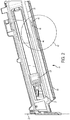
FIG. 1 is a perspective view of an embodiment of a fastening tool and support foot. -
FIG. 2 is an enlarged elevational detail view of a magazine of the fastening tool ofFIG. 1 . -
FIG. 3 is a detail of the circled region ofFIG. 2 . -
FIG. 4 is an enlarged partial elevational sectional view taken along line 4-4 ofFIG. 1 . -
FIG. 5A is a perspective detail view of an embodiment of a support foot. -
FIGS. 5B and 5D are side elevational views of the support foot ofFIG. 5A . -
FIG. 5C is a top plan view of the support foot ofFIG. 5A . -
FIGS. 5E and 5F are elevational views taken from the rear and the front, respectively, of the support foot ofFIG. 5A . -
FIG. 5G is an elevational sectional view taken alongline 5G-5G ofFIG. 5C . -
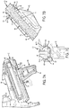
FIG. 6A is a partial exploded perspective view of the fastening tool and support foot ofFIG. 1 , showing an upper surface of the support foot being moved toward a lower surface of the fastening tool. -
FIG. 6B is an elevational sectional detail view taken alongline 6B-6B ofFIG. 6A . -
FIG. 7A is a view similar to that ofFIG. 6A , showing the support foot being moved along tracks of the fastening tool so that leading edges of the support foot begin to deflect away from male detents formed on the tracks. -
FIG. 7B is a horizontal sectional detail view taken alongline 7B-7B ofFIG. 7A . -
FIG. 7C is a view similar to that ofFIG. 6B , taken alongline 7C-7C ofFIG. 7A . -
FIG. 8A is a view similar to that ofFIG. 7A and showing the support foot having been moved on the tracks to a position where respective detents cooperate to retain the support foot in place. -
FIGS. 8B and 8C are views similar to those ofFIGS. 7B and 7C , respectively, but showing the support foot positioned as shown inFIG. 8A . -
FIG. 9A is a partial perspective detail view of a support foot positioned on the lower surface of the fastening tool ofFIG. 1 , but oriented at an incorrect orientation relative to the fastening tool. -
FIG. 9B is a horizontal sectional detail view taken alongline 9B-9B ofFIG. 9A . -
FIG. 9C is a view similar to that ofFIG. 9A , but showing the support foot being blocked from traveling along the tracks. -
FIG. 9D is a horizontal sectional detail view taken alongline 9D-9D ofFIG. 9C . -
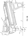
FIG. 10A is a partial elevational detail view of the fastening tool and support foot ofFIG. 1 , where the contact trip has a height H1. -
FIG. 10B is a view similar to that ofFIG. 10A , but where the contact trip height has been increased to H2. -
FIG. 10C is a view similar to that ofFIG. 10B , showing that the support foot has been positioned on the fastening tool ofFIG. 1 to compensate for the change in height of the contact trip. -
FIG. 11A is an enlarged elevational detail view of the lower surface of a second embodiment of a fastening tool. -
FIG. 11B is a horizontal sectional view taken along theline 11 B-11 B ofFIG. 11A , but showing the support foot attached to the fastening tool. -
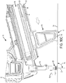
FIG. 12 shows another embodiment of a fastening tool and support foot, in which the support foot is mounted directly upon a lower surface of the fastening tool housing. - Referring now to the drawings and particularly to
FIG. 1 , afastening tool 10 includes ahousing 12, a motor 14 (shown in phantom) disposed in the housing, abattery pack 16 for providing power to the motor, and a drive system including a drive bar (not shown) configured for driving a fastener and being operatively associated with the motor, such as, for example, by use of a flywheel. The drive system further includes adrive track 18 and acontact trip 20, disposed along adrive axis 22, which is oriented at a desired angle A relative to awork surface 24. - Continuing to refer to
FIG. 1 , afastener magazine 40 is attached to anunderside 26 of thehousing 12, and a support member orfoot 60 is removably attached to the magazine. Although thefastening tool 10 is depicted as having amagazine 40 to which thesupport foot 60 is attached, it is important to note that the support foot may also be directly attached to theunderside 26 of the fastening tool, in the event the fastening tool does not have a magazine, or in the event that the fastening tool magazine is disposed in a location on thehousing 12 other than at the underside. Such an embodiment of thefastening tool 200 is shown inFIG. 12 . Consequently, for the purposes of this description, a "lower surface" 28 of thefastening tool 10 is defined generally to include not only theunderside 26 ofhousing 12, but also to include themagazine 40, so that it can be seen that thesupport foot 60 is readily usable with either type of fastening tool (see bracketedregion 28 inFIG. 1 ). - As is also shown in
FIG. 1 , one purpose of thesupport foot 60 is to maintain a desired orientation of the fasteningtool drive axis 22 at an angle A with awork surface 24. Accordingly, it should also be noted that, although some embodiments are described in connection with an electric-powered concrete nailer, themagazine 40 andsupport foot 60 may be used with any type of fastening tool, including without limitation staplers and other nailers. Furthermore, such fastening tools may use other types of drive systems, including without limitation hydraulic, pneumatic, combustion/gas, and explosive/powder-actuated systems. Therefore, regardless of the type of fastening tool, themagazine 40 andsupport foot 60 will be operative to maintain the desired orientation at an angle A. - Now referring to
FIGS. 1- 3 , themagazine 40 is configured to holdnails 27 oriented in parallel with thedrive axis 22, and defines anengagement portion 42 of thelower surface 28 that cooperates with thesupport foot 60 to retain the support foot on thefastening tool 10. Theengagement portion 42 includes atrack 44 disposed on each side of themagazine 40, each track defining amale detent 46 and astop 48. As shown inFIG. 4 ,magazine 40 is also equipped with a retainingguard 50. -
FIG. 1 shows thesupport foot 60 disposed on thetrack 44 so that the support foot engages thestop 48. At this location of thesupport foot 60 on thelower surface 28, various elements of the support foot and themagazine 40 cooperate to releasably retain the support foot in the position shown inFIG. 1 . This cooperation maintains the orientation of the fasteningtool drive axis 22 at the angle A relative to worksurface 24. -
FIGS. 5A-5G detail the features of thesupport foot 60, which defines anupper surface 62 and a work surface-engagingportion 64 disposed at the bottom of the support foot. Theupper surface 62 in turn defines two opposed parallel slots orchannels 66, each having an openfront end 68 and a closed rear end 70 (FIG. 5G ). Theupper surface 62 further defines two opposedfemale detents 72 and aleading edge 74. In some embodiments of thesupport foot 60, the support foot is manufactured from glass-filled nylon so that the support foot has a slight amount of resiliency. - A method of releasably attaching the
support foot 62 to thelower surface 28 of thefastening tool 10 is illustrated inFIGS. 6A through 8C . Thesupport foot 60, oriented at a desiredorientation 71 relative to thefastening tool 10, is moved toward themagazine 40, as shown inFIGS. 6A and 6B , so that theupper surface 62 of the support foot engages thelower surface 28 of the fastening tool. Then, as shown particularly inFIG. 7A , thesupport foot 60 is moved along thelower surface 28 until respective channels orslots 66 in the support foot engage correspondingtracks 44 on the lower surface. The fastening tool operator continues to move thesupport foot 60 in the direction shown by the arrow inFIG. 7A untilmale detents 46 cause theleading edges 74 of the support foot to deflect slightly away from themale detents 46, as shown by the arrows inFIG. 7B , and by the phantom line positions of the support foot inFIG. 7C . - As shown in
FIGS. 8A through 8C , the fastening tool operator continues to slide thesupport foot 60 along thetrack 44 until respectivemale detents 46 become nested in their correspondingfemale detents 72.Stops 48 may also engage respectiveleading edges 74 of thesupport foot 60 to prevent the support foot from traveling past the position shown inFIG. 8B . It should be noted that, in some embodiments, themagazine 40 is manufactured from glass-filled polypropylene. Consequently the process depicted so far shows thesupport foot 60 deflecting away fromdetents 46 formed on themagazine 40. However, if desired, the magazine can be manufactured so that a portion of the magazine, namely, themale detents 46, deflect inwardly away from the leadingedges 74 of the support foot, instead. In this case, for example, the magazine detents may be formed of a suitable plastic such as DELRIN ® plastic, or nylon without glass fill. - The
support foot 60 is prevented from being attached to thelower surface 28 backwards. In this event, when thesupport foot 60 is positioned againstmagazine 40 at an incorrect orientation 71', was illustrated inFIGS. 9A-9D , such that the closedrear end 70 of the support foot is placed closer to thetracks 44 than the openfront end 68 of the support foot, the closed front end is blocked by the tracks (seeFIGS. 9B and 9D ). This prevents thesupport foot 60 from being moved along thetracks 44, and thus prevents the support foot from being attached to thelower surface 26 of thefastening tool 10 at the incorrect orientation 71' (namely, backwards). -
FIGS. 10A-10C illustrate a method for compensating for the use of a height-adjustment system to change the height of thecontact trip 20 relative to thework surface 24.FIG. 10A shows the angle A1 of thedrive axis 22 when the height of the contact trip is set at H1, and when the location of the work surface-engagingportion 64 of thesupport foot 60 is at L1. If the contact trip height is increased to H2, as shown inFIG. 10B , the drive axis 22' becomes skewed to form a different angle A2 relative to thework surface 24. Also, a portion of the work surface-engagingportion 64 is lifted slightly off thework surface 24. To compensate for the increase in contact trip height, and to bring the angle of the drive axis 22' relative to thework surface 24 back to angle A1, the fastening tool operator merely moves thesupport foot 60 by hand along thetracks 44 in a first direction shown by the arrow inFIG. 10C , until the respective male andfemale detents support foot 60 along thelower surface 28 until the support foot reaches a location L2 where the work surface-engagingportion 64 of the support foot engages thework surface 24, such that thedrive axis 22 is oriented once again at angle A1. - If it is desired to retain the
support foot 60 at the position shown, for example, inFIG. 10C , thelower surface 28 of thefastening tool 10 may be modified as shown inFIGS. 11A and 11B . Here the magazine 40' now defines first and secondmale detents 46', 46" which cooperate with thefemale detents 72 of thesupport foot 60, in the same manner as is shown inFIG. 8B when a single set ofmale detents 46 are used, so that the support foot can be retained at two different locations relative to thefastening tool 10. Using no tools, the operator merely moves thesupport foot 60 as shown by the arrow inFIG. 11A so that the support foot engages the lower surface 28 (in this case, of magazine 40'), then moves the support foot along the lower surface until the support foot engages thetrack 44, as was previously described. The operator then slides thesupport foot 60 along thetrack 44 until the support foot is retained in place either by male detents 46' or bymale detents 46". To remove thesupport foot 60, the operator simply reverses the process. The operator, using hand pressure only, simply slidessupport foot 60 in the opposite direction along thetracks 44 until the support foot is disengaged from themale detents 46', 46". Then, the operator continues to move thesupport foot 60 until the support foot clears thetracks 44. At that point, all the operator has to do is move thesupport foot 60 away from thelower surface 28 of thefastening tool 10. Of course, if desired, more than twodetents 46 may be used. - The
support foot 60 may also be mounted directly to alower surface 228 of another embodiment of thefastening tool 200, as shown inFIG. 12 . Here,fastening tool 200 includes ahousing 220 which defines anunderside 226, upon which are formed tracks 244, detents 246, and stops 248, which are configured similarly to theirrespective counterparts support foot 60 thus similarly maintains adrive axis 222 oriented at a desired angle A relative to thework surface 24. - It can now be seen that various embodiments of the fastening tool, magazine and support foot address the need for an inexpensive system for easily but securely attaching a support foot to a fastening tool, so that the support foot can be removably retained at a desired location on the fastening tool, all without the use of any tools whatsoever.
- It will be appreciated that whilst various aspects and embodiments of the present invention have heretofore been described, the scope of the present invention is not limited to the embodiments set out herein and instead extends to encompass all arrangements, and modifications and alterations thereto, which fall within the spirit and scope of the appended claims.
Claims (15)
- A method of removably attaching a support foot to a lower surface of a fastening tool, comprising:moving the support foot toward the fastening tool so that the support foot engages the lower surface; anddeflecting a portion of the support foot over a portion of the lower surface or deflecting a portion of the lower surface over a portion of the support foot.
- The method claimed in Claim 1, further comprising:prior to the deflecting step, moving the support foot along the lower surface of the fastening tool until the support foot reaches a desired position relative to the fastening tool.
- The method claimed in Claim 2, wherein:the support foot is moved along the lower surface of the fastening tool so that the support foot and a portion of the lower surface of the fastening tool cooperate to attach and retain the support foot in the desired position.
- The method claimed in Claim 4, wherein the support foot and the portion of the lower surface of the fastening tool each define a detent, and
wherein the respective detents are caused to cooperate to retain the support foot in the desired position. - The method claimed in Claim 4, wherein a portion of the support foot deflects to permit the support foot to ride over the detent formed on the portion of the lower surface of the fastening tool.
- The method claimed in any of Claims 1 to 5, wherein the lower surface of the fastening tool defines two opposing tracks, and
wherein the support foot defines two opposing channels operatively associated with respective opposing tracks and further comprising the steps of:moving the support foot in a first direction along the lower surface of the fastening tool; andengaging the channels with respective tracks. - The method claimed in Claim 6, wherein the tracks define at least one male detent, and
wherein the channels define at least one female detent that cooperates with the at least one male detent to releasably retain the support foot on the tracks at a desired location. - The method claimed in Claim 7, further comprising:moving the support foot in a second direction, opposite to the first direction, along the tracks so that the at least one female detent is disengaged from the at least one male detent;continuing to move the support foot along the lower surface of the fastening tool until the channels clear the tracks; andmoving the support foot away from the fastening tool.
- A fastening tool, comprising:a housing having an underside;a fastener drive system disposed in the housing, the fastener drive system including a drive track disposed along a drive axis;a magazine containing fasteners, the magazine connected to the housing and configured to present fasteners to the drive track to be driven by the drive system into a work surface;a support member removably attached to one of the underside and the magazine and being movable to a desired position on one of the underside and the magazine to maintain a desired angle of the drive axis relative to the work surface,wherein one of the support member, the housing underside, and the magazine is deformable to retain the support member in the desired position.
- The fastening tool claimed in Claim 21, wherein no tools are required to retain the support member in the desired position.
- The fastening tool claimed in Claim 9 or 10, wherein one of the underside and the magazine defining two tracks arranged in parallel,
wherein the support member defines slots arranged in parallel and engageable with respective tracks, and
wherein the support member is slidable along the tracks. - The fastening tool claimed in Claim 11, wherein the tracks and slots define respective cooperating detents such that the support member may be retained at a desired position on the tracks.
- The fastening tool claimed in Claim 11 or 12, wherein each track defines a plurality of male detents,
wherein each slot defines a plurality of female detents cooperating with respective male detents, and
wherein the support member may be retained at a plurality of desired positions on the tracks corresponding to the respective positions of the plurality of male detents. - The fastening tool claimed in any of Claims 11 to 13, further comprising:a stop formed at one end of each track to limit the distance that the support member may be moved along the tracks.
- The fastening tool as claimed in any of Claims 11 to 14, wherein each slot defines an open front end and a closed rear end such that the support member is blocked from moving along the tracks by the closed rear end when the support member engages the fastening tool with the closed rear end closer to the tracks than the open front end.
Applications Claiming Priority (1)
| Application Number | Priority Date | Filing Date | Title |
|---|---|---|---|
| US15/195,095 US11325235B2 (en) | 2016-06-28 | 2016-06-28 | Push-on support member for fastening tools |
Publications (2)
| Publication Number | Publication Date |
|---|---|
| EP3272464A1 true EP3272464A1 (en) | 2018-01-24 |
| EP3272464B1 EP3272464B1 (en) | 2019-04-17 |
Family
ID=59215615
Family Applications (1)
| Application Number | Title | Priority Date | Filing Date |
|---|---|---|---|
| EP17177702.2A Active EP3272464B1 (en) | 2016-06-28 | 2017-06-23 | Push-on support member for fastening tools |
Country Status (3)
| Country | Link |
|---|---|
| US (2) | US11325235B2 (en) |
| EP (1) | EP3272464B1 (en) |
| ES (1) | ES2726934T3 (en) |
Families Citing this family (8)
| Publication number | Priority date | Publication date | Assignee | Title |
|---|---|---|---|---|
| US11325235B2 (en) * | 2016-06-28 | 2022-05-10 | Black & Decker, Inc. | Push-on support member for fastening tools |
| US10828761B2 (en) * | 2016-08-15 | 2020-11-10 | Illinois Tool Works Inc. | Powered fastener driving tool |
| CA3153933A1 (en) * | 2019-09-10 | 2021-03-18 | Pneutools, Inc. | Directional clinching tool and nails |
| US12514656B2 (en) * | 2021-05-27 | 2026-01-06 | Covidien Lp | Surgical robotic systems |
| US12576494B2 (en) * | 2021-09-15 | 2026-03-17 | Robert Bosch Gmbh | Protective support structure for nailer |
| US20240139893A1 (en) * | 2022-10-28 | 2024-05-02 | House of Design LLC | Auto feed fastener tool |
| US20240261876A1 (en) * | 2023-02-08 | 2024-08-08 | Phillips Screw Company | Depth setter tool |
| JP2025075967A (en) * | 2023-11-01 | 2025-05-15 | 株式会社マキタ | Driving tools |
Citations (4)
| Publication number | Priority date | Publication date | Assignee | Title |
|---|---|---|---|---|
| US5261588A (en) * | 1992-05-22 | 1993-11-16 | Joseph Lin | Improvement for a nailing gun |
| US20090152323A1 (en) * | 2007-12-17 | 2009-06-18 | Sandy LIN | Position scale on nail gun |
| EP2687334A2 (en) * | 2012-07-19 | 2014-01-22 | HILTI Aktiengesellschaft | Nailing device |
| US20160129573A1 (en) * | 2014-11-10 | 2016-05-12 | Powernail Company | Adjustable fastener-driving tool support system |
Family Cites Families (321)
| Publication number | Priority date | Publication date | Assignee | Title |
|---|---|---|---|---|
| US1526025A (en) | 1920-03-23 | 1925-02-10 | Clement F Street | Locomotive starting device |
| US1988827A (en) * | 1932-10-07 | 1935-01-22 | Scovill Manufacturing Co | Electrically heated tool |
| GB602455A (en) | 1943-10-01 | 1948-05-27 | Philco Radio & Television Corp | Method and means for translating mechanical energy |
| US2594605A (en) * | 1946-12-23 | 1952-04-29 | Rop Loc Products Co | Adjustable supporting bar |
| US2822698A (en) | 1953-05-14 | 1958-02-11 | Arthur R Gross | Control mechanism |
| US2745689A (en) * | 1955-02-23 | 1956-05-15 | Tinnerman Products Inc | Knob connection or the like |
| US2979725A (en) | 1957-09-10 | 1961-04-18 | Fastener Corp | Fastener driving apparatus |
| US3141360A (en) * | 1963-02-18 | 1964-07-21 | Wolf Samuel | Guided electric drill |
| US3172124A (en) | 1963-04-01 | 1965-03-09 | Spotnails | Pneumatically operated fastener driving machines |
| US3225443A (en) * | 1964-07-23 | 1965-12-28 | Ingersoll Rand Canada | Support means for vibratory hand-held power tools |
| CH488473A (en) * | 1967-12-21 | 1970-04-15 | Mattel Inc | Game |
| US3570739A (en) | 1968-07-07 | 1971-03-16 | Dieter Volkmann | Pneumatically operated fastener device |
| US3563438A (en) | 1968-12-05 | 1971-02-16 | Fastener Corp | Fastener driving tool |
| US3603281A (en) * | 1969-12-15 | 1971-09-07 | Spectrol Electronics Corp | Dial mechanism for electronic components |
| US3659768A (en) | 1970-06-12 | 1972-05-02 | Olin Corp | Fastener driving tool |
| US3658229A (en) | 1970-07-30 | 1972-04-25 | Omark Industries Inc | Stud driving tool |
| DE2101499C3 (en) | 1971-01-14 | 1979-07-12 | Impex-Essen Vertrieb Von Werkzeugen Gmbh, 8800 Ansbach | Feed device in the case of bolt setters for a magazine strip carrying cartridges |
| US3768846A (en) * | 1971-06-03 | 1973-10-30 | R Hensley | Interlocking joint |
| US3774293A (en) | 1971-09-13 | 1973-11-27 | Signode Corp | Fastener driving tool |
| US3767114A (en) * | 1971-11-23 | 1973-10-23 | Rivarossi Spa | Device for retaining rails of miniature trains |
| US3765588A (en) | 1972-02-07 | 1973-10-16 | E Frederickson | Nail feeding apparatus |
| US3827822A (en) * | 1972-06-29 | 1974-08-06 | D Converse | Guided tool |
| US3820705A (en) | 1972-08-07 | 1974-06-28 | W Beals | Nailing machine |
| US3854648A (en) * | 1972-10-04 | 1974-12-17 | G Inzoli | Air operated fastener driving tool, especially for tacks |
| US3890058A (en) * | 1973-11-01 | 1975-06-17 | Rhodes Investment Company | Drill guiding apparatus |
| US3893610A (en) | 1974-03-13 | 1975-07-08 | Arthur J Smith | Pneumatic device for driving headed objects |
| US3979040A (en) | 1975-09-22 | 1976-09-07 | Adam Denin | Nail driver |
| US4033499A (en) | 1975-10-20 | 1977-07-05 | Butler David J | Fastener applicators |
| US4049181A (en) | 1975-12-04 | 1977-09-20 | Shigemasa Kametaki | Automatic nailing machine |
| DE2718070A1 (en) | 1977-04-22 | 1978-10-26 | Signode Corp | ADDITIONAL EQUIPMENT FOR PNEUMATIC DRIVING DEVICES |
| US4129240A (en) | 1977-07-05 | 1978-12-12 | Duo-Fast Corporation | Electric nailer |
| JPS5499276A (en) | 1978-01-21 | 1979-08-04 | Matsushita Electric Works Ltd | Nailing machine |
| US4197974A (en) | 1978-06-12 | 1980-04-15 | Speedfast Corporation | Nailer |
| US4375867A (en) * | 1978-07-05 | 1983-03-08 | Duo-Fast Corporation | Electric fastener driving tool |
| US4230249A (en) * | 1978-07-05 | 1980-10-28 | Duo-Fast Corporation | Hand-held fastener driving tool |
| DE2838194C3 (en) | 1978-09-01 | 1982-02-11 | Karl M. Reich Maschinenfabrik GmbH, 7440 Nürtingen | Device for feeding and separating fastening means |
| US4313552A (en) | 1978-09-01 | 1982-02-02 | Firma Karl M. Reich Maschinenfabrik Gmbh | Apparatus for driving fasteners |
| DE2928827C2 (en) * | 1979-07-17 | 1981-07-30 | Milos 7000 Stuttgart Kaderabek | Soldering tips for electric soldering irons and soldering devices with an insulating jacket to dampen heat radiation, with a preferred embodiment of the electric soldering iron |
| US4270587A (en) * | 1979-08-02 | 1981-06-02 | Ludy Andrew W | Nail holder for hammers |
| US4314782A (en) * | 1979-08-06 | 1982-02-09 | Black & Decker Inc. | Tool guide |
| US4304349B1 (en) | 1979-10-09 | 1996-02-27 | Duo Fast Cord | Fastener driving tool |
| US4316513A (en) | 1980-02-04 | 1982-02-23 | Dwight Harris | Nail driving impact hammer |
| DE3018382C2 (en) | 1980-05-14 | 1986-11-13 | Walter 6730 Neustadt Medinger | Device for automatically feeding screws to the screw pin of a screwdriver, in particular a drywall screwdriver |
| US4404894A (en) | 1980-08-27 | 1983-09-20 | Hilti Aktiengesellschaft | Valve trigger assembly for pneumatic nailer |
| US4403725A (en) | 1981-03-06 | 1983-09-13 | Lawrence Noel A | Nail holding and directing device |
| US4389012A (en) | 1981-04-22 | 1983-06-21 | Duo-Fast Corporation | Fastener tool loading assembly |
| US4468159A (en) * | 1981-12-07 | 1984-08-28 | Oster Stanley M | Drill press and stand |
| US4424929A (en) | 1982-03-16 | 1984-01-10 | Power-Wire Fastener Systems, Inc. | Clip magazine feed for fastener driving tools |
| US4487355A (en) | 1982-05-07 | 1984-12-11 | Ginnow Oscar H | Nailing machine |
| US4485952A (en) | 1982-06-03 | 1984-12-04 | Power-Line Fastener Systems, Inc. | Shiftable magazine clip feed for fastener driving tools |
| DK133284A (en) | 1983-03-11 | 1984-09-12 | Signode Corp | HUMBLE DRIVER AND HUMBLE STORAGE UNIT |
| US4519535A (en) | 1983-03-29 | 1985-05-28 | Sencorp | Flywheel for an electro-mechanical fastener driving tool |
| US4566621A (en) | 1984-07-03 | 1986-01-28 | Sencorp | Means for associating a driver, constituting a part of a replaceable fastener containing magazine, with the driver operating mechanism of a fastener driving tool |
| US4597517A (en) | 1985-06-21 | 1986-07-01 | Signode Corporation | Magazine interlock for a fastener driving device |
| US4667747A (en) | 1985-08-19 | 1987-05-26 | Falls Jack L | Nail starter |
| DE3572324D1 (en) * | 1985-12-14 | 1989-09-21 | Behrens Ag Friedrich Joh | Magazine for a power-driven tool for driving pins or nails or the like |
| DE8704666U1 (en) | 1986-08-02 | 1987-05-21 | Demba Metallwarenfabrik GmbH, 2072 Bargteheide | Electrically operated tacker |
| US4765786A (en) * | 1987-05-28 | 1988-08-23 | Krogh Kris K | Drill guide |
| US4810137A (en) * | 1987-06-22 | 1989-03-07 | Yang Tai Her | Double-use electrical drill |
| US4854393A (en) * | 1987-12-03 | 1989-08-08 | Palet Timothy J | Combination air hammer, water stream blaster and liquid mist dust suppressor |
| US4834342A (en) | 1988-05-20 | 1989-05-30 | Edwin Padgett | Nail driver |
| US4863089A (en) | 1988-11-16 | 1989-09-05 | Senco Products, Inc. | Flagless nail driving tool |
| US4912848A (en) * | 1989-01-09 | 1990-04-03 | Textron, Inc. | Power tool handle |
| US5006022A (en) * | 1989-05-02 | 1991-04-09 | Bernard Miller | Axially movable tool and guide |
| US5025968A (en) | 1989-06-19 | 1991-06-25 | Duo-Fast Corporation | Furniture tool |
| DE4011778C2 (en) | 1989-09-08 | 1995-06-01 | Hitachi Koki Kk | Pneumatic impact tool for fasteners |
| US4967623A (en) | 1990-01-25 | 1990-11-06 | Jackson Linda K | Nail support apparatus |
| US5134812A (en) * | 1990-04-04 | 1992-08-04 | Ingalls Shipbuilding, Inc. | Mechanical connector for structural members |
| DE9016493U1 (en) | 1990-12-05 | 1991-03-14 | Paslode GmbH, 6236 Eschborn | Nail driver |
| SE468837B (en) * | 1991-07-12 | 1993-03-29 | Anders Svensson | HAALLARE |
| NZ245193A (en) * | 1991-11-20 | 1995-11-27 | Stratco Australia Pty Ltd | U-shaped bracket base fitted in end of a tubular member and bracket arms clamped to opposite grooved sides of adjoining frame member |
| US5147162A (en) * | 1992-02-20 | 1992-09-15 | Rosario Capotosto | Self-guidable drill housing |
| US5292013A (en) * | 1992-10-23 | 1994-03-08 | E-Systems, Inc. | Support ferrules |
| JP3239579B2 (en) | 1993-02-05 | 2001-12-17 | 日立工機株式会社 | Nailing machine |
| JPH06246649A (en) | 1993-02-25 | 1994-09-06 | Ryobi Ltd | Reaction absorbing device for driving machine |
| US5368213A (en) | 1993-04-29 | 1994-11-29 | Senco Products, Inc. | Magazine for a pneumatic fastener driving tool |
| AU667162B2 (en) | 1993-05-13 | 1996-03-07 | Stanley-Bostitch, Inc. | Fastener driving device particularly suited for use as a roofing nailer |
| US5575051A (en) | 1993-06-10 | 1996-11-19 | Marson/Creative Fastener Group | High impact power tool having shock absorbing means |
| US5405071A (en) * | 1993-08-24 | 1995-04-11 | Baugus; Michael | Nail gun head elevating tool |
| US5484094A (en) | 1994-06-16 | 1996-01-16 | Illinois Tool Works Inc. | Workpiece-contacting probe for fastener-driving tool for fastening lath to substrate |
| US5478002A (en) | 1994-06-17 | 1995-12-26 | Sigma Tool & Machine, Partnership Of Sigma Tool & Machine Ltd. | Magnetic tee-nut holder |
| US5445479A (en) * | 1994-08-17 | 1995-08-29 | Hillinger; George | Ergonomically designed, electrically energized hand drill having a housing, longitudinally aligned with a hand, wrist and forearm support |
| JP3301232B2 (en) | 1994-10-14 | 2002-07-15 | 日立工機株式会社 | Driver blade for driving machine |
| SE9500810D0 (en) * | 1995-03-07 | 1995-03-07 | Perstorp Flooring Ab | Floor tile |
| US5649661A (en) | 1995-03-28 | 1997-07-22 | Max Co., Ltd. | Equipment for nailing machine |
| US5628445A (en) * | 1995-06-05 | 1997-05-13 | Senco Products, Inc. | Shingle gauge for use with nail driving tool |
| US5588577A (en) | 1995-06-14 | 1996-12-31 | Testo Industry Corp. | Magazine assembly for pneumatic staple guns |
| CA2226777C (en) * | 1995-07-13 | 2007-04-10 | Atlas Copco Berema Aktiebolag | Handle means for percussive hand held machines |
| US5779145A (en) * | 1995-11-06 | 1998-07-14 | Zelle; David A. | Device for securing railroad tracks for train sets |
| US5829660A (en) * | 1995-12-07 | 1998-11-03 | Stanley-Bostitch, Inc. | Automatic-type fastener driving device |
| US5695108A (en) | 1996-03-05 | 1997-12-09 | De Poan Pneumatic Corporation | Magazine system of a stapler |
| US5711471A (en) | 1996-03-19 | 1998-01-27 | Stanley-Bostitch, Inc. | Magnetic biased driving element for a fastener driving tool |
| US5813588A (en) | 1996-10-09 | 1998-09-29 | Lin; George | Magazine assembly for fastener driving tools |
| US5831817A (en) * | 1997-06-16 | 1998-11-03 | Mitac International Corporation | Computer apparatus having a movable liquid crystal display |
| US5816468A (en) | 1997-06-24 | 1998-10-06 | Testo Industries Corp. | No-idle-striking structure for nailing machines |
| US5931364A (en) | 1997-06-25 | 1999-08-03 | Acme Staple Company, Inc. | Fastening tool for securing an object to a substrate |
| US5921562A (en) | 1998-01-27 | 1999-07-13 | Robison; Troy | Magnetic chuck assembly |
| US6145723A (en) | 1998-01-27 | 2000-11-14 | Illinois Tool Works Inc. | Workpiece-contacting probe for fastener-driving tool for fastening dimpled membranes to foundation walls via fasteners and polymeric plugs |
| JP2000015590A (en) | 1998-07-01 | 2000-01-18 | Makita Corp | Nailing machine |
| US6053389A (en) | 1998-08-05 | 2000-04-25 | Sup Drogon Enterprise Co., Ltd. | Nailing gun magazine specially designed for big nail set |
| JP3558884B2 (en) | 1998-08-10 | 2004-08-25 | 株式会社マキタ | Nailing machine |
| US6036072A (en) | 1998-10-27 | 2000-03-14 | De Poan Pneumatic Corporation | Nailer magazine |
| US6536536B1 (en) * | 1999-04-29 | 2003-03-25 | Stephen F. Gass | Power tools |
| JP2000354981A (en) | 1999-06-10 | 2000-12-26 | Max Co Ltd | Blank driving prevention device for fastening machine |
| US6131787A (en) | 1999-07-27 | 2000-10-17 | Illinois Tool Works Inc. | Two-piece nailer magazine and method therefor |
| US6189759B1 (en) | 1999-08-06 | 2001-02-20 | Stanley Fastening Systems, Lp | Fastener driving device with enhanced magazine latch assembly |
| US6371348B1 (en) | 1999-08-06 | 2002-04-16 | Stanley Fastening Systems, Lp | Fastener driving device with enhanced sequential actuation |
| US6056181A (en) | 1999-08-24 | 2000-05-02 | Besco Pneumatic Corp. | Fastening machine |
| DE29917830U1 (en) | 1999-10-09 | 2000-02-24 | Erwin Müller GmbH & Co, 49808 Lingen | Tacker, especially hand tacker |
| US6149046A (en) | 1999-11-01 | 2000-11-21 | Basso Industry Corp. | Safety device for preventing ejecting mechanism from hitting pushing member in a magazine of a power stapler |
| CA2339296C (en) * | 2000-03-03 | 2006-05-09 | John Dickhaut | Accessory device for nail and staple guns |
| US6308879B1 (en) | 2000-04-14 | 2001-10-30 | Besco Pneumatic Corp. | Device for positioning nails in a tube of a nailer |
| JP3780822B2 (en) | 2000-05-23 | 2006-05-31 | 日立工機株式会社 | Nailer |
| USRE42987E1 (en) | 2000-05-23 | 2011-12-06 | Hitachi Koki Co., Ltd. | Nail gun with safety portion mechanism for preventing misfires |
| US6454151B1 (en) | 2000-07-17 | 2002-09-24 | Lin Wang-Kuan | Power stapler |
| US6431428B1 (en) | 2000-10-16 | 2002-08-13 | Jui-Chin Chen | Pneumatic nail gun |
| EP1657027B1 (en) | 2000-11-16 | 2008-02-13 | Max Co., Ltd. | Connected nail supplying mechanism for nailing machine |
| US6796475B2 (en) | 2000-12-22 | 2004-09-28 | Senco Products, Inc. | Speed controller for flywheel operated hand tool |
| US20020185514A1 (en) | 2000-12-22 | 2002-12-12 | Shane Adams | Control module for flywheel operated hand tool |
| JP3832247B2 (en) | 2001-01-19 | 2006-10-11 | 日立工機株式会社 | Nail driving device |
| US6609646B2 (en) | 2001-02-08 | 2003-08-26 | Black & Decker Inc. | Magazine assembly for fastening tool |
| US6679413B2 (en) | 2001-02-08 | 2004-01-20 | Black & Decker Inc. | Magazine assembly for fastening tool |
| DE10106050B4 (en) * | 2001-02-09 | 2017-02-16 | Hilti Aktiengesellschaft | Hand tool with an additional handle |
| US6408770B1 (en) * | 2001-03-15 | 2002-06-25 | Food Machinery Equipment Corporation | Adjustable pallet protector assembly for a single pallet or an array of pallets |
| US6913180B2 (en) | 2001-07-16 | 2005-07-05 | George A. Schuster | Nail gun |
| US6557743B2 (en) | 2001-07-16 | 2003-05-06 | George A. Schuster | Multi chamber nail gun |
| US6364192B1 (en) | 2001-07-19 | 2002-04-02 | Wang-Kuan Lin | Device for preventing action rod of nailer from descending |
| US7692667B2 (en) * | 2001-08-17 | 2010-04-06 | Palm, Inc. | Handheld computer having moveable segments that are interactive with an integrated display |
| US6918527B2 (en) | 2001-08-23 | 2005-07-19 | Max Co., Ltd. | Staple cartridge of electric stapler |
| US7410084B1 (en) | 2001-08-31 | 2008-08-12 | Reed Daniel J | Multiple-impact adapter for a hammer tool |
| US20030146262A1 (en) | 2002-02-07 | 2003-08-07 | Senco Products, Inc. | Fastener positioning apparatus for a fastener driving tool |
| US9038305B2 (en) | 2013-06-20 | 2015-05-26 | Torrey Pines Logic, Inc. | Quick-detach accessory base mount for an accessory rail |
| US6796389B2 (en) * | 2002-03-28 | 2004-09-28 | Snap-On Incorporated | Power hand tool and removable grip therefor |
| US6679414B2 (en) | 2002-06-13 | 2004-01-20 | Illinois Tool Works Inc. | Interchangeable magazine for a tool |
| JP3861756B2 (en) | 2002-06-17 | 2006-12-20 | マックス株式会社 | Nail tilt prevention mechanism in nailing machine |
| US6598775B1 (en) | 2002-08-30 | 2003-07-29 | Tung-Hsien Chen | Hammer head assembly for power hammer |
| US6789718B2 (en) | 2002-09-17 | 2004-09-14 | Stanley Fastening Systems, L.P. | Nail placement device |
| US20060102685A1 (en) | 2002-09-18 | 2006-05-18 | Alan Phillips | Top load/side load adjustable angle magazine |
| US7025242B1 (en) * | 2002-09-18 | 2006-04-11 | Black & Decker Inc. | Adjustable angle magazine |
| JP4111085B2 (en) | 2002-11-01 | 2008-07-02 | 日立工機株式会社 | Nailer |
| US6585142B1 (en) | 2002-12-02 | 2003-07-01 | Tung-Hsien Chen | Hammer head assembly used in an air nailing gun for driving U-nails |
| TW567966U (en) | 2002-12-26 | 2003-12-21 | Wen-Jou Jang | Nailing gun structure |
| JP4181488B2 (en) | 2003-02-07 | 2008-11-12 | 株式会社マキタ | Driving machine |
| ITBO20030105A1 (en) | 2003-02-28 | 2004-09-01 | Fasco Spa | PNEUMATIC GUN FOR FIXING ELEMENTS. |
| US6805272B1 (en) | 2003-08-06 | 2004-10-19 | Yang Sen-Mu | Pneumatic nail driver |
| USD551931S1 (en) | 2003-11-19 | 2007-10-02 | Black & Decker Inc. | Pneumatic fastener |
| USD498127S1 (en) | 2003-11-19 | 2004-11-09 | Porter-Cable Corporation | Pneumatic fastener |
| US20050166713A1 (en) | 2004-01-29 | 2005-08-04 | Lloyd Rickey G. | Nail holders and methods |
| US6908021B1 (en) | 2004-02-04 | 2005-06-21 | Nailermate Enterprise Corp. | Safety catch mechanism of nail guns |
| WO2005087449A1 (en) * | 2004-03-15 | 2005-09-22 | Maxtech Manufacturing Inc. | Rotary tool with improved connecting means for attachments thereto |
| US7789169B2 (en) | 2004-04-02 | 2010-09-07 | Black & Decker Inc. | Driver configuration for a power tool |
| US8123099B2 (en) | 2004-04-02 | 2012-02-28 | Black & Decker Inc. | Cam and clutch configuration for a power tool |
| US7137541B2 (en) | 2004-04-02 | 2006-11-21 | Black & Decker Inc. | Fastening tool with mode selector switch |
| US8231039B2 (en) | 2004-04-02 | 2012-07-31 | Black & Decker Inc. | Structural backbone/motor mount for a power tool |
| US7686199B2 (en) | 2004-04-02 | 2010-03-30 | Black & Decker Inc. | Lower bumper configuration for a power tool |
| US7975893B2 (en) | 2004-04-02 | 2011-07-12 | Black & Decker Inc. | Return cord assembly for a power tool |
| US20050217416A1 (en) | 2004-04-02 | 2005-10-06 | Alan Berry | Overmolded article and method for forming same |
| US8408327B2 (en) | 2004-04-02 | 2013-04-02 | Black & Decker Inc. | Method for operating a power driver |
| US8302833B2 (en) | 2004-04-02 | 2012-11-06 | Black & Decker Inc. | Power take off for cordless nailer |
| US7165305B2 (en) | 2004-04-02 | 2007-01-23 | Black & Decker Inc. | Activation arm assembly method |
| US7204403B2 (en) | 2004-04-02 | 2007-04-17 | Black & Decker Inc. | Activation arm configuration for a power tool |
| ATE394200T1 (en) | 2004-04-02 | 2008-05-15 | Black & Decker Inc | FASTENING TOOL WITH MODE SELECTION SWITCH |
| US7503401B2 (en) | 2004-04-02 | 2009-03-17 | Black & Decker Inc. | Solenoid positioning methodology |
| US7331403B2 (en) | 2004-04-02 | 2008-02-19 | Black & Decker Inc. | Lock-out for activation arm mechanism in a power tool |
| US7322506B2 (en) | 2004-04-02 | 2008-01-29 | Black & Decker Inc. | Electric driving tool with driver propelled by flywheel inertia |
| US7285877B2 (en) | 2004-04-02 | 2007-10-23 | Black & Decker Inc. | Electronic fastening tool |
| US7138595B2 (en) | 2004-04-02 | 2006-11-21 | Black & Decker Inc. | Trigger configuration for a power tool |
| US7726536B2 (en) | 2004-04-02 | 2010-06-01 | Black & Decker Inc. | Upper bumper configuration for a power tool |
| US8011549B2 (en) | 2004-04-02 | 2011-09-06 | Black & Decker Inc. | Flywheel configuration for a power tool |
| US7044351B2 (en) | 2004-05-03 | 2006-05-16 | Fasco S.P.A. | Modular magazine of fixing element for pneumatic gun |
| JP4446794B2 (en) * | 2004-05-10 | 2010-04-07 | ダイキョーニシカワ株式会社 | Member connection structure |
| US6948647B1 (en) * | 2004-05-25 | 2005-09-27 | Black & Decker Inc. | Anti-slip shingle grip for fastening tool |
| FR2871081B1 (en) | 2004-06-02 | 2006-08-11 | Prospection Et D Inv S Techniq | APPARATUS FOR FASTENING FIXING ELEMENTS WITH MEANS FOR CLAMPING AND PLACING A DISMANTLING POWER STORE AND FEEDING STORE FOR THE FIXING DEVICE |
| US7134586B2 (en) | 2004-06-30 | 2006-11-14 | Stanley Fastening Systems, L.P. | Fastener driving device |
| US7100475B1 (en) | 2004-07-22 | 2006-09-05 | Rufolo Jr Joseph | Nail holder |
| JP4569252B2 (en) | 2004-10-08 | 2010-10-27 | マックス株式会社 | Power driven nailer |
| US7055728B2 (en) | 2004-10-28 | 2006-06-06 | Basso Industry Corp. | Positioning structure for nailer |
| US6971567B1 (en) | 2004-10-29 | 2005-12-06 | Black & Decker Inc. | Electronic control of a cordless fastening tool |
| US6966477B1 (en) | 2004-11-15 | 2005-11-22 | Basso Industry Corp | Safety device for preventing a nailer from dry firing |
| US7086573B1 (en) | 2005-01-28 | 2006-08-08 | De Poan Pneumatic | Brake device for de-actuating a nail driver without nails therein |
| US7140524B2 (en) | 2005-02-14 | 2006-11-28 | Basso Industry Corp. | Nailing machine with a safety mechanism |
| CA112358S (en) | 2005-03-02 | 2006-08-11 | Max Co Ltd | Pneumatic nailing machine |
| US7328826B2 (en) | 2005-03-28 | 2008-02-12 | Illinois Tool Works Inc. | Power nailer with driver blade blocking mechanism magazine |
| JP4930670B2 (en) | 2005-04-01 | 2012-05-16 | マックス株式会社 | Motor holding mechanism of gas combustion type driving tool |
| CA2542324C (en) | 2005-04-08 | 2012-07-10 | Eazypower Corporation | A magnetic device for holding and driving bits and fasteners |
| US20060231582A1 (en) | 2005-04-14 | 2006-10-19 | Eastway Fair Company Limited | Stapler |
| CA2544149A1 (en) * | 2005-04-19 | 2006-10-19 | Toni P. Bannister | Variable height interlocking moulding strip for flooring |
| US7930960B2 (en) * | 2005-05-06 | 2011-04-26 | Allen Ip, Incorporated | Universal machinery fence system |
| US8505798B2 (en) | 2005-05-12 | 2013-08-13 | Stanley Fastening Systems, L.P. | Fastener driving device |
| JP5034177B2 (en) | 2005-05-25 | 2012-09-26 | マックス株式会社 | Driving tool safety device |
| US7225960B2 (en) | 2005-06-07 | 2007-06-05 | Hsiu-Chiang Chen | Locking device for magazine of staplers |
| JP4930672B2 (en) | 2005-08-09 | 2012-05-16 | マックス株式会社 | Fastener feed mechanism for gas-fired driving tools |
| US7775403B2 (en) * | 2005-08-31 | 2010-08-17 | Robert Bosch Gmbh | Power hand tool having a retractable front stand |
| US7547167B2 (en) * | 2005-09-16 | 2009-06-16 | Robert Bosch Gmbh | Storage drawer for hand-held power tool |
| EP1777040B1 (en) | 2005-10-19 | 2013-01-16 | Makita Corporation | Power tool |
| US20070090148A1 (en) | 2005-10-20 | 2007-04-26 | Jeil Tacker Co., Ltd. | Coil nailer for construction finish material |
| US7303103B2 (en) | 2005-12-02 | 2007-12-04 | Nailermate Enterprise Corp. | Structure of arresting mechanism for nail guns |
| JP2007160411A (en) | 2005-12-09 | 2007-06-28 | Makita Corp | Idle blow preventing device of driving machine |
| US7931026B2 (en) * | 2006-01-20 | 2011-04-26 | Ric Investments, Llc | Adjustable conduit coupling assembly |
| US7571844B2 (en) | 2006-01-26 | 2009-08-11 | Sigma Tool & Machine, A Partnership Between Sigma Tool & Machine Ltd. And Sigma Fasteners, Ltd. | Pneumatic hand tool for inserting t-nuts |
| US20070261868A1 (en) | 2006-05-12 | 2007-11-15 | Gross James R | Magnetic torque-limiting device and method |
| US7552852B2 (en) | 2006-05-15 | 2009-06-30 | Michael Lee Haskins | Nail holding and driving device |
| USD556003S1 (en) | 2006-05-26 | 2007-11-27 | Black & Decker Inc. | Nailer |
| USD562664S1 (en) | 2006-05-26 | 2008-02-26 | Black & Decker Inc. | Nailer |
| US7284685B1 (en) | 2006-07-27 | 2007-10-23 | Black & Decker Inc. | Pusher bearing and pusher block for magazine feeder |
| JP2008068356A (en) | 2006-09-14 | 2008-03-27 | Hitachi Koki Co Ltd | Electric driving machine |
| JP4692933B2 (en) | 2006-09-14 | 2011-06-01 | 日立工機株式会社 | Electric driving machine |
| JP4692932B2 (en) | 2006-09-14 | 2011-06-01 | 日立工機株式会社 | Electric driving machine |
| JP4556188B2 (en) | 2006-09-14 | 2010-10-06 | 日立工機株式会社 | Electric driving machine |
| JP4861106B2 (en) | 2006-09-21 | 2012-01-25 | 株式会社マキタ | Electric driving machine |
| EP2066472A4 (en) * | 2006-10-06 | 2011-02-02 | Black & Decker Inc | Joist drill |
| US7451735B2 (en) * | 2006-10-13 | 2008-11-18 | Ford Global Technologies, Llc | Flexibly-jointed, fluid-tight cover for internal combustion engine |
| DE102006048719A1 (en) * | 2006-10-16 | 2008-04-17 | Robert Bosch Gmbh | System with a hand tool |
| US7753243B2 (en) | 2006-10-25 | 2010-07-13 | Black & Decker Inc. | Lock-out mechanism for a power tool |
| ITTO20060816A1 (en) | 2006-11-16 | 2008-05-17 | Cane Srl | STRIPE FOR SYRINGE AND SYRINGE THAT ENCOURAGES THE STOVE |
| TW200824856A (en) | 2006-12-08 | 2008-06-16 | Basso Ind Corp | Nail gun with safety device |
| JP4789788B2 (en) | 2006-12-11 | 2011-10-12 | 株式会社マキタ | Driving tool |
| TW200833478A (en) | 2007-02-15 | 2008-08-16 | Basso Ind Corp | Percussion control device of nail gun |
| JP4939985B2 (en) | 2007-03-16 | 2012-05-30 | 株式会社マキタ | Driving tool |
| US7646157B2 (en) | 2007-03-16 | 2010-01-12 | Black & Decker Inc. | Driving tool and method for controlling same |
| US7413103B1 (en) | 2007-03-22 | 2008-08-19 | Apach Industrial Co., Ltd. | Dry firing prevention device for nail gun |
| JP5395333B2 (en) | 2007-05-11 | 2014-01-22 | 日立工機株式会社 | Driving machine |
| US7565992B2 (en) * | 2007-05-23 | 2009-07-28 | Illinois Tool Works Inc. | Collapsible protective tip for fastener driver workpiece contact element |
| CN201061875Y (en) | 2007-05-29 | 2008-05-21 | 车王电子股份有限公司 | Staple cartridge shared by U-shaped staple and T-shaped staple |
| US7484647B2 (en) | 2007-06-04 | 2009-02-03 | Testo Industry Corp. | Nail gun with a safety assembly |
| US7556184B2 (en) | 2007-06-11 | 2009-07-07 | Black & Decker Inc. | Profile lifter for a nailer |
| JP5073380B2 (en) | 2007-06-28 | 2012-11-14 | 株式会社マキタ | Electric driving tool |
| TW200906571A (en) | 2007-08-03 | 2009-02-16 | De Poan Pneumatic Corp | Rocking type kinetic energy clutching device of electric nailing gun device |
| TW200909148A (en) | 2007-08-21 | 2009-03-01 | Rexon Ind Corp Ltd | Nail cartridge angle adjusting device of the nail gun |
| TW200909147A (en) | 2007-08-21 | 2009-03-01 | Rexon Ind Corp Ltd | Spiking guide unit of nail gun |
| US7690546B2 (en) | 2007-08-31 | 2010-04-06 | Illinois Tool Works Inc. | Pneumatic tool actuation device |
| JP5182549B2 (en) | 2007-09-28 | 2013-04-17 | 日立工機株式会社 | Driving machine |
| US7575140B2 (en) * | 2007-09-28 | 2009-08-18 | De Poan Pneumatic Corp. | Abutment adjusting device for nail gun |
| US8011547B2 (en) | 2007-10-05 | 2011-09-06 | Senco Brands, Inc. | Fastener driving tool using a gas spring |
| US8763874B2 (en) | 2007-10-05 | 2014-07-01 | Senco Brands, Inc. | Gas spring fastener driving tool with improved lifter and latch mechanisms |
| US20090108046A1 (en) | 2007-10-24 | 2009-04-30 | Chi-Sheng Huang | Trigger Switch Mechanism for Nail Gun |
| US20090120281A1 (en) | 2007-11-09 | 2009-05-14 | Testo Industry Corp. | Magnetic-tipped piston |
| US8104658B2 (en) | 2007-11-20 | 2012-01-31 | De Poan Pneumatic Corp. | Block device for nail gun |
| US7575141B1 (en) | 2008-02-04 | 2009-08-18 | De Poan Pneumatic Corp. | Actuator for electrical nail gun |
| DE102008000835A1 (en) | 2008-03-26 | 2009-10-01 | Hilti Aktiengesellschaft | setting tool |
| DE102008000831A1 (en) | 2008-03-26 | 2009-10-01 | Hilti Aktiengesellschaft | setting tool |
| US8534527B2 (en) | 2008-04-03 | 2013-09-17 | Black & Decker Inc. | Cordless framing nailer |
| US8827132B2 (en) * | 2008-04-23 | 2014-09-09 | Illinois Tool Works Inc. | Fastener driving tool and workpiece positioning attachments |
| EP2123406B1 (en) * | 2008-05-19 | 2011-12-21 | AEG Electric Tools GmbH | Vibration dampened holder for additional hand grip |
| CN101585182B (en) | 2008-05-23 | 2011-08-31 | 台州市大江实业有限公司 | Nailing gun firing safety device and nailing gun installed with same |
| US7934565B2 (en) | 2008-08-14 | 2011-05-03 | Robert Bosch Gmbh | Cordless nailer with safety sensor |
| US8136606B2 (en) | 2008-08-14 | 2012-03-20 | Robert Bosch Gmbh | Cordless nail gun |
| US7905377B2 (en) | 2008-08-14 | 2011-03-15 | Robert Bosch Gmbh | Flywheel driven nailer with safety mechanism |
| US7934566B2 (en) | 2008-08-14 | 2011-05-03 | Robert Bosch Gmbh | Cordless nailer drive mechanism sensor |
| CA2736521A1 (en) | 2008-09-09 | 2010-03-18 | Sonette Myburgh, Trustee For The Herman Myburgh Preservation Trust | Nail driving tool mechanism |
| US7874469B2 (en) | 2008-09-18 | 2011-01-25 | Basso Industry Corp. | Nailing depth adjustable device for a nail gun |
| US8381830B2 (en) | 2009-05-05 | 2013-02-26 | Black & Decker Inc. | Power tool with integrated bit retention device |
| US8042717B2 (en) | 2009-04-13 | 2011-10-25 | Stanley Fastening Systems, Lp | Fastener driving device with contact trip having an electrical actuator |
| US20100301091A1 (en) | 2009-06-01 | 2010-12-02 | Chia-Sheng Liang | Linkage Mechanism between Trigger Valve and Control Valve in Pneumatic Nail Guns |
| US8387846B2 (en) * | 2009-06-08 | 2013-03-05 | Illinois Tool Works Inc | Fastening tool with blind guide work contact tip |
| US7870987B1 (en) * | 2009-06-30 | 2011-01-18 | Robert Bosch Gmbh | Fastener driving tool with protection inserts |
| JP2011088269A (en) | 2009-09-25 | 2011-05-06 | Makita Corp | Driving tool |
| TW201117930A (en) | 2009-11-19 | 2011-06-01 | De Poan Pneumatic Corp | Driving device for resetting a nail hitting bar the a pneumatic nail gun |
| US8998684B2 (en) * | 2009-12-03 | 2015-04-07 | Cembre S.P.A. | Apparatus for the tooling of a workpiece |
| US8631986B2 (en) | 2009-12-04 | 2014-01-21 | Robert Bosch Gmbh | Fastener driver with an operating switch |
| EP2539095A1 (en) * | 2010-02-25 | 2013-01-02 | Demain Technology Pty Ltd. | Modular power tool |
| US8061437B2 (en) | 2010-03-04 | 2011-11-22 | De Poan Pneumatic Corp. | Nail gun with rapidly attachable and detachable magazine assembly |
| US20110278342A1 (en) | 2010-05-17 | 2011-11-17 | De Poan Pneumatic Corp. | Nail gun with improved attachable and detachable magazine assembly |
| DE102010030410B4 (en) | 2010-06-23 | 2012-05-10 | Hilti Aktiengesellschaft | Screwdrivers and control methods |
| US20110315840A1 (en) | 2010-06-28 | 2011-12-29 | Dan Connolly | Universal cam lock mount |
| CN102398249B (en) | 2010-09-09 | 2014-07-30 | 南京德朔实业有限公司 | Power tool with automatic nail feeding apparatus |
| US8833626B2 (en) | 2010-09-29 | 2014-09-16 | Stanley Fastening Systems, L.P. | Fastening tool |
| US8292143B2 (en) | 2010-10-12 | 2012-10-23 | Stanley Fastening Systems, L.P. | Dry fire lockout with bypass for fastener driving device |
| US8931178B2 (en) * | 2011-02-24 | 2015-01-13 | Albert Beam | Clipper deflector for deflecting air and cuttings away from operator |
| US8469634B2 (en) | 2011-07-29 | 2013-06-25 | Pgs Geophysical As | Method and system of depth triggers for marine geophysical survey cable retriever systems |
| US8991675B2 (en) | 2011-12-19 | 2015-03-31 | De Poan Pneumatic Corp. | Dynamic clutch apparatus for electrical nail gun |
| US9630305B1 (en) * | 2012-02-13 | 2017-04-25 | W. C. Litzinger | Pneumatic nailer outrigger stabalizing foot |
| US9649756B1 (en) * | 2012-02-13 | 2017-05-16 | William C. Litzinger | Pneumatic nailer outrigger stabalizing foot |
| US9908226B1 (en) * | 2013-02-13 | 2018-03-06 | W. C. Litzinger | Birds beak elastomer fastener magazine feeder |
| US9120028B2 (en) * | 2012-02-17 | 2015-09-01 | Roy Wilson | Device for adapting toy roadway track and bricks |
| US9346156B1 (en) | 2012-02-21 | 2016-05-24 | Senco Brands, Inc. | Skewed fastener track for improved alignment and fastener drivability |
| US8925233B2 (en) | 2012-02-21 | 2015-01-06 | Alan T. Thordsen | Ambidextrous tool-actuated covered magazine release |
| US9010493B2 (en) | 2012-03-13 | 2015-04-21 | Caterpillar Inc. | Lubrication arrangement |
| US9469021B2 (en) | 2012-05-31 | 2016-10-18 | Black & Decker Inc. | Fastening tool nail channel |
| US9486904B2 (en) | 2012-05-31 | 2016-11-08 | Black & Decker Inc. | Fastening tool nosepiece insert |
| US9498871B2 (en) | 2012-05-31 | 2016-11-22 | Black & Decker Inc. | Power tool raving spring curl trip actuator |
| US9643305B2 (en) | 2012-05-31 | 2017-05-09 | Black & Decker Inc. | Magazine assembly for fastening tool |
| US11229995B2 (en) | 2012-05-31 | 2022-01-25 | Black Decker Inc. | Fastening tool nail stop |
| US9649755B2 (en) | 2012-05-31 | 2017-05-16 | Black & Decker Inc. | Power tool having angled dry fire lockout |
| US9827658B2 (en) | 2012-05-31 | 2017-11-28 | Black & Decker Inc. | Power tool having latched pusher assembly |
| US20130320063A1 (en) | 2012-05-31 | 2013-12-05 | Black & Decker, Inc. | Fastening tool nail feed funnel |
| US9577493B2 (en) | 2012-09-20 | 2017-02-21 | Black & Decker Inc. | Motor and electronics cooling system for a high power cordless nailer |
| US9346158B2 (en) | 2012-09-20 | 2016-05-24 | Black & Decker Inc. | Magnetic profile lifter |
| US9399281B2 (en) | 2012-09-20 | 2016-07-26 | Black & Decker Inc. | Stall release lever for fastening tool |
| US9744657B2 (en) | 2012-10-04 | 2017-08-29 | Black & Decker Inc. | Activation system having multi-angled arm and stall release mechanism |
| CN203125467U (en) * | 2013-01-17 | 2013-08-14 | 郭景煌 | A new nail shooter |
| US9511416B2 (en) * | 2013-01-18 | 2016-12-06 | Gage Bilt, Inc. | Feed devices for swagable lockbolt collars |
| US9459075B1 (en) * | 2013-04-30 | 2016-10-04 | Rapid Entry Technologies, LLC | Elevated sight |
| EP2992290B1 (en) | 2013-05-03 | 2018-06-20 | Sturm, Ruger & Company, Inc. | Universal magazine latch mechanism for firearm |
| TWM463638U (en) | 2013-06-05 | 2013-10-21 | Basso Ind Corp | Nail cartridge preventing dislocation of nail row |
| US12502756B2 (en) | 2013-10-09 | 2025-12-23 | Black & Decker Inc. | High inertia driver system |
| US10434634B2 (en) | 2013-10-09 | 2019-10-08 | Black & Decker, Inc. | Nailer driver blade stop |
| US9527196B2 (en) | 2013-11-06 | 2016-12-27 | Illinois Tool Works Inc. | Fastener driving tool with an automatic nose chamber guide member |
| CN203566643U (en) * | 2013-11-21 | 2014-04-30 | 浙江荣鹏气动工具有限公司 | Quick-release three-in-one pneumatic toenail gun |
| US20150306754A1 (en) | 2014-04-24 | 2015-10-29 | Illinois Tool Works Inc. | Disc positioning attachment for a fastener driving tool |
| TWI607839B (en) | 2014-06-05 | 2017-12-11 | Basso Ind Corp | Portable power tool and impact block resetting device |
| US9643200B2 (en) * | 2014-12-19 | 2017-05-09 | Richard A. Belanger | Squeeze container liquid extrusion tool |
| CA2988510C (en) * | 2015-06-08 | 2023-09-26 | Paul E. Fiala | Guide for a fastener hand tool |
| CN109070321B (en) | 2016-04-12 | 2022-04-08 | 株式会社牧田 | Break in tool |
| US11325235B2 (en) * | 2016-06-28 | 2022-05-10 | Black & Decker, Inc. | Push-on support member for fastening tools |
| US11267114B2 (en) * | 2016-06-29 | 2022-03-08 | Black & Decker, Inc. | Single-motion magazine retention for fastening tools |
| US11279013B2 (en) | 2016-06-30 | 2022-03-22 | Black & Decker, Inc. | Driver rebound plate for a fastening tool |
| US10987790B2 (en) | 2016-06-30 | 2021-04-27 | Black & Decker Inc. | Cordless concrete nailer with improved power take-off mechanism |
| EP3269512B1 (en) | 2016-07-12 | 2018-12-05 | Makita Corporation | Driving tool |
| CA2981019A1 (en) * | 2016-10-10 | 2018-04-10 | Power Tech Staple and Nail, Inc. | Accessory attachment for driven fastener hand tool |
| US10870195B2 (en) * | 2016-12-06 | 2020-12-22 | Black & Decker Inc. | Power tool with storage system |
| US10926385B2 (en) * | 2017-02-24 | 2021-02-23 | Black & Decker, Inc. | Contact trip having magnetic filter |
| KR102274121B1 (en) | 2017-04-03 | 2021-07-06 | 현대자동차주식회사 | Motor-driven steering column device for vehicle |
| US10888987B2 (en) * | 2017-05-04 | 2021-01-12 | Skitter & Squirt Adventures, Llc | Power tool ski system and method |
| EP3403787B1 (en) | 2017-05-19 | 2019-07-31 | Joh. Friedrich Behrens AG | Driving tool for driving fastening means into workpieces |
| DK3572189T3 (en) * | 2018-01-19 | 2021-09-20 | Max Co Ltd | Recovery tool |
| WO2019168849A1 (en) * | 2018-02-27 | 2019-09-06 | Milwaukee Electric Tool Corporation | Length adjustable level |
| US20190275625A1 (en) * | 2018-03-10 | 2019-09-12 | Chad Weissenfels | Gauge |
| CN108465842B (en) * | 2018-03-11 | 2019-07-09 | 福州清河源环保科技有限公司 | A kind of anti-bias electric hand drill facilitating control drilling depth |
| US10723005B2 (en) | 2018-03-28 | 2020-07-28 | Black & Decker Inc. | Electric fastener driving tool assembly including a driver home position sensor |
| DE102018207066A1 (en) * | 2018-05-07 | 2019-11-07 | Robert Bosch Gmbh | drilling |
-
2016
- 2016-06-28 US US15/195,095 patent/US11325235B2/en active Active
-
2017
- 2017-06-23 ES ES17177702T patent/ES2726934T3/en active Active
- 2017-06-23 EP EP17177702.2A patent/EP3272464B1/en active Active
-
2022
- 2022-04-12 US US17/718,732 patent/US20220234186A1/en active Pending
Patent Citations (4)
| Publication number | Priority date | Publication date | Assignee | Title |
|---|---|---|---|---|
| US5261588A (en) * | 1992-05-22 | 1993-11-16 | Joseph Lin | Improvement for a nailing gun |
| US20090152323A1 (en) * | 2007-12-17 | 2009-06-18 | Sandy LIN | Position scale on nail gun |
| EP2687334A2 (en) * | 2012-07-19 | 2014-01-22 | HILTI Aktiengesellschaft | Nailing device |
| US20160129573A1 (en) * | 2014-11-10 | 2016-05-12 | Powernail Company | Adjustable fastener-driving tool support system |
Also Published As
| Publication number | Publication date |
|---|---|
| ES2726934T3 (en) | 2019-10-10 |
| US20220234186A1 (en) | 2022-07-28 |
| EP3272464B1 (en) | 2019-04-17 |
| US20170368672A1 (en) | 2017-12-28 |
| US11325235B2 (en) | 2022-05-10 |
Similar Documents
| Publication | Publication Date | Title |
|---|---|---|
| EP3272464B1 (en) | Push-on support member for fastening tools | |
| EP3437803B1 (en) | Dry-fire lockout mechanism for a powered fastener driver | |
| US10498115B2 (en) | Irrigation control box with offset hinge assembly | |
| US8752744B2 (en) | Portable tools | |
| US20130221056A1 (en) | Nail gun | |
| EP3263282B1 (en) | Fastening tool and method of removably retaining a magazine thereon | |
| US12304046B2 (en) | Nailing device | |
| CN103764438A (en) | Seat Sliders for Vehicles | |
| EP1604784A1 (en) | Clincher for stapler | |
| US20090224130A1 (en) | Longitudinal guide for motor vehicle seats which are adjustable in a longitudinal direction and also removable | |
| GB2515191A (en) | Staple cartridge, stapler, and interface | |
| US7721817B2 (en) | Fastener driving device with adjustable shoe | |
| CN110050169B (en) | Magazine connector | |
| CA3102822C (en) | Working end for a nail driving tool | |
| EP3646990A1 (en) | Work accessory for stapler | |
| EP2505314B1 (en) | Driving tool | |
| US11777171B2 (en) | Buckling structure for a battery of a handheld power tool | |
| US7083074B2 (en) | Fastening structure for cover and top seat of magazine of stapling gun nose | |
| JP6848625B2 (en) | Stapler | |
| JP6926607B2 (en) | Stapler | |
| GB2555118B (en) | Parts of a gap controlling clip, a gap controlling clip and a method | |
| JPH0537471U (en) | Nail supply guide device for nailer | |
| WO2009029042A1 (en) | Feed member for a staple magazine of a stapler in order to prevent jamming |
Legal Events
| Date | Code | Title | Description |
|---|---|---|---|
| PUAI | Public reference made under article 153(3) epc to a published international application that has entered the european phase |
Free format text: ORIGINAL CODE: 0009012 |
|
| STAA | Information on the status of an ep patent application or granted ep patent |
Free format text: STATUS: THE APPLICATION HAS BEEN PUBLISHED |
|
| AK | Designated contracting states |
Kind code of ref document: A1 Designated state(s): AL AT BE BG CH CY CZ DE DK EE ES FI FR GB GR HR HU IE IS IT LI LT LU LV MC MK MT NL NO PL PT RO RS SE SI SK SM TR |
|
| AX | Request for extension of the european patent |
Extension state: BA ME |
|
| STAA | Information on the status of an ep patent application or granted ep patent |
Free format text: STATUS: REQUEST FOR EXAMINATION WAS MADE |
|
| 17P | Request for examination filed |
Effective date: 20180709 |
|
| RBV | Designated contracting states (corrected) |
Designated state(s): AL AT BE BG CH CY CZ DE DK EE ES FI FR GB GR HR HU IE IS IT LI LT LU LV MC MK MT NL NO PL PT RO RS SE SI SK SM TR |
|
| GRAP | Despatch of communication of intention to grant a patent |
Free format text: ORIGINAL CODE: EPIDOSNIGR1 |
|
| STAA | Information on the status of an ep patent application or granted ep patent |
Free format text: STATUS: GRANT OF PATENT IS INTENDED |
|
| RIC1 | Information provided on ipc code assigned before grant |
Ipc: B25C 7/00 20060101AFI20181102BHEP |
|
| INTG | Intention to grant announced |
Effective date: 20181206 |
|
| RIN1 | Information on inventor provided before grant (corrected) |
Inventor name: JASKOT, ERIN Inventor name: MEYER, JEFFREY Inventor name: GARBER, STUART |
|
| GRAS | Grant fee paid |
Free format text: ORIGINAL CODE: EPIDOSNIGR3 |
|
| GRAA | (expected) grant |
Free format text: ORIGINAL CODE: 0009210 |
|
| STAA | Information on the status of an ep patent application or granted ep patent |
Free format text: STATUS: THE PATENT HAS BEEN GRANTED |
|
| AK | Designated contracting states |
Kind code of ref document: B1 Designated state(s): AL AT BE BG CH CY CZ DE DK EE ES FI FR GB GR HR HU IE IS IT LI LT LU LV MC MK MT NL NO PL PT RO RS SE SI SK SM TR |
|
| REG | Reference to a national code |
Ref country code: GB Ref legal event code: FG4D |
|
| REG | Reference to a national code |
Ref country code: CH Ref legal event code: EP |
|
| REG | Reference to a national code |
Ref country code: DE Ref legal event code: R096 Ref document number: 602017003311 Country of ref document: DE |
|
| REG | Reference to a national code |
Ref country code: AT Ref legal event code: REF Ref document number: 1121036 Country of ref document: AT Kind code of ref document: T Effective date: 20190515 Ref country code: IE Ref legal event code: FG4D |
|
| REG | Reference to a national code |
Ref country code: SE Ref legal event code: TRGR |
|
| REG | Reference to a national code |
Ref country code: NL Ref legal event code: MP Effective date: 20190417 |
|
| PGFP | Annual fee paid to national office [announced via postgrant information from national office to epo] |
Ref country code: FR Payment date: 20190510 Year of fee payment: 3 Ref country code: SE Payment date: 20190611 Year of fee payment: 3 |
|
| REG | Reference to a national code |
Ref country code: LT Ref legal event code: MG4D |
|
| PG25 | Lapsed in a contracting state [announced via postgrant information from national office to epo] |
Ref country code: NL Free format text: LAPSE BECAUSE OF FAILURE TO SUBMIT A TRANSLATION OF THE DESCRIPTION OR TO PAY THE FEE WITHIN THE PRESCRIBED TIME-LIMIT Effective date: 20190417 |
|
| REG | Reference to a national code |
Ref country code: ES Ref legal event code: FG2A Ref document number: 2726934 Country of ref document: ES Kind code of ref document: T3 Effective date: 20191010 |
|
| PG25 | Lapsed in a contracting state [announced via postgrant information from national office to epo] |
Ref country code: HR Free format text: LAPSE BECAUSE OF FAILURE TO SUBMIT A TRANSLATION OF THE DESCRIPTION OR TO PAY THE FEE WITHIN THE PRESCRIBED TIME-LIMIT Effective date: 20190417 Ref country code: LT Free format text: LAPSE BECAUSE OF FAILURE TO SUBMIT A TRANSLATION OF THE DESCRIPTION OR TO PAY THE FEE WITHIN THE PRESCRIBED TIME-LIMIT Effective date: 20190417 Ref country code: FI Free format text: LAPSE BECAUSE OF FAILURE TO SUBMIT A TRANSLATION OF THE DESCRIPTION OR TO PAY THE FEE WITHIN THE PRESCRIBED TIME-LIMIT Effective date: 20190417 Ref country code: NO Free format text: LAPSE BECAUSE OF FAILURE TO SUBMIT A TRANSLATION OF THE DESCRIPTION OR TO PAY THE FEE WITHIN THE PRESCRIBED TIME-LIMIT Effective date: 20190717 Ref country code: AL Free format text: LAPSE BECAUSE OF FAILURE TO SUBMIT A TRANSLATION OF THE DESCRIPTION OR TO PAY THE FEE WITHIN THE PRESCRIBED TIME-LIMIT Effective date: 20190417 Ref country code: PT Free format text: LAPSE BECAUSE OF FAILURE TO SUBMIT A TRANSLATION OF THE DESCRIPTION OR TO PAY THE FEE WITHIN THE PRESCRIBED TIME-LIMIT Effective date: 20190817 |
|
| PGFP | Annual fee paid to national office [announced via postgrant information from national office to epo] |
Ref country code: ES Payment date: 20190701 Year of fee payment: 3 |
|
| PG25 | Lapsed in a contracting state [announced via postgrant information from national office to epo] |
Ref country code: BG Free format text: LAPSE BECAUSE OF FAILURE TO SUBMIT A TRANSLATION OF THE DESCRIPTION OR TO PAY THE FEE WITHIN THE PRESCRIBED TIME-LIMIT Effective date: 20190717 Ref country code: GR Free format text: LAPSE BECAUSE OF FAILURE TO SUBMIT A TRANSLATION OF THE DESCRIPTION OR TO PAY THE FEE WITHIN THE PRESCRIBED TIME-LIMIT Effective date: 20190718 Ref country code: RS Free format text: LAPSE BECAUSE OF FAILURE TO SUBMIT A TRANSLATION OF THE DESCRIPTION OR TO PAY THE FEE WITHIN THE PRESCRIBED TIME-LIMIT Effective date: 20190417 Ref country code: LV Free format text: LAPSE BECAUSE OF FAILURE TO SUBMIT A TRANSLATION OF THE DESCRIPTION OR TO PAY THE FEE WITHIN THE PRESCRIBED TIME-LIMIT Effective date: 20190417 Ref country code: PL Free format text: LAPSE BECAUSE OF FAILURE TO SUBMIT A TRANSLATION OF THE DESCRIPTION OR TO PAY THE FEE WITHIN THE PRESCRIBED TIME-LIMIT Effective date: 20190417 |
|
| REG | Reference to a national code |
Ref country code: AT Ref legal event code: MK05 Ref document number: 1121036 Country of ref document: AT Kind code of ref document: T Effective date: 20190417 |
|
| PG25 | Lapsed in a contracting state [announced via postgrant information from national office to epo] |
Ref country code: IS Free format text: LAPSE BECAUSE OF FAILURE TO SUBMIT A TRANSLATION OF THE DESCRIPTION OR TO PAY THE FEE WITHIN THE PRESCRIBED TIME-LIMIT Effective date: 20190817 |
|
| REG | Reference to a national code |
Ref country code: DE Ref legal event code: R097 Ref document number: 602017003311 Country of ref document: DE |
|
| PG25 | Lapsed in a contracting state [announced via postgrant information from national office to epo] |
Ref country code: EE Free format text: LAPSE BECAUSE OF FAILURE TO SUBMIT A TRANSLATION OF THE DESCRIPTION OR TO PAY THE FEE WITHIN THE PRESCRIBED TIME-LIMIT Effective date: 20190417 Ref country code: SK Free format text: LAPSE BECAUSE OF FAILURE TO SUBMIT A TRANSLATION OF THE DESCRIPTION OR TO PAY THE FEE WITHIN THE PRESCRIBED TIME-LIMIT Effective date: 20190417 Ref country code: AT Free format text: LAPSE BECAUSE OF FAILURE TO SUBMIT A TRANSLATION OF THE DESCRIPTION OR TO PAY THE FEE WITHIN THE PRESCRIBED TIME-LIMIT Effective date: 20190417 Ref country code: DK Free format text: LAPSE BECAUSE OF FAILURE TO SUBMIT A TRANSLATION OF THE DESCRIPTION OR TO PAY THE FEE WITHIN THE PRESCRIBED TIME-LIMIT Effective date: 20190417 Ref country code: MC Free format text: LAPSE BECAUSE OF FAILURE TO SUBMIT A TRANSLATION OF THE DESCRIPTION OR TO PAY THE FEE WITHIN THE PRESCRIBED TIME-LIMIT Effective date: 20190417 Ref country code: RO Free format text: LAPSE BECAUSE OF FAILURE TO SUBMIT A TRANSLATION OF THE DESCRIPTION OR TO PAY THE FEE WITHIN THE PRESCRIBED TIME-LIMIT Effective date: 20190417 Ref country code: CZ Free format text: LAPSE BECAUSE OF FAILURE TO SUBMIT A TRANSLATION OF THE DESCRIPTION OR TO PAY THE FEE WITHIN THE PRESCRIBED TIME-LIMIT Effective date: 20190417 |
|
| PLBE | No opposition filed within time limit |
Free format text: ORIGINAL CODE: 0009261 |
|
| STAA | Information on the status of an ep patent application or granted ep patent |
Free format text: STATUS: NO OPPOSITION FILED WITHIN TIME LIMIT |
|
| PG25 | Lapsed in a contracting state [announced via postgrant information from national office to epo] |
Ref country code: SM Free format text: LAPSE BECAUSE OF FAILURE TO SUBMIT A TRANSLATION OF THE DESCRIPTION OR TO PAY THE FEE WITHIN THE PRESCRIBED TIME-LIMIT Effective date: 20190417 Ref country code: IT Free format text: LAPSE BECAUSE OF FAILURE TO SUBMIT A TRANSLATION OF THE DESCRIPTION OR TO PAY THE FEE WITHIN THE PRESCRIBED TIME-LIMIT Effective date: 20190417 |
|
| 26N | No opposition filed |
Effective date: 20200120 |
|
| REG | Reference to a national code |
Ref country code: BE Ref legal event code: MM Effective date: 20190630 |
|
| PG25 | Lapsed in a contracting state [announced via postgrant information from national office to epo] |
Ref country code: TR Free format text: LAPSE BECAUSE OF FAILURE TO SUBMIT A TRANSLATION OF THE DESCRIPTION OR TO PAY THE FEE WITHIN THE PRESCRIBED TIME-LIMIT Effective date: 20190417 |
|
| PG25 | Lapsed in a contracting state [announced via postgrant information from national office to epo] |
Ref country code: IE Free format text: LAPSE BECAUSE OF NON-PAYMENT OF DUE FEES Effective date: 20190623 |
|
| PG25 | Lapsed in a contracting state [announced via postgrant information from national office to epo] |
Ref country code: BE Free format text: LAPSE BECAUSE OF NON-PAYMENT OF DUE FEES Effective date: 20190630 Ref country code: LU Free format text: LAPSE BECAUSE OF NON-PAYMENT OF DUE FEES Effective date: 20190623 Ref country code: SI Free format text: LAPSE BECAUSE OF FAILURE TO SUBMIT A TRANSLATION OF THE DESCRIPTION OR TO PAY THE FEE WITHIN THE PRESCRIBED TIME-LIMIT Effective date: 20190417 |
|
| REG | Reference to a national code |
Ref country code: CH Ref legal event code: PL |
|
| PG25 | Lapsed in a contracting state [announced via postgrant information from national office to epo] |
Ref country code: LI Free format text: LAPSE BECAUSE OF NON-PAYMENT OF DUE FEES Effective date: 20200630 Ref country code: CH Free format text: LAPSE BECAUSE OF NON-PAYMENT OF DUE FEES Effective date: 20200630 Ref country code: FR Free format text: LAPSE BECAUSE OF NON-PAYMENT OF DUE FEES Effective date: 20200630 |
|
| PG25 | Lapsed in a contracting state [announced via postgrant information from national office to epo] |
Ref country code: SE Free format text: LAPSE BECAUSE OF NON-PAYMENT OF DUE FEES Effective date: 20200624 Ref country code: CY Free format text: LAPSE BECAUSE OF FAILURE TO SUBMIT A TRANSLATION OF THE DESCRIPTION OR TO PAY THE FEE WITHIN THE PRESCRIBED TIME-LIMIT Effective date: 20190417 |
|
| PG25 | Lapsed in a contracting state [announced via postgrant information from national office to epo] |
Ref country code: MT Free format text: LAPSE BECAUSE OF FAILURE TO SUBMIT A TRANSLATION OF THE DESCRIPTION OR TO PAY THE FEE WITHIN THE PRESCRIBED TIME-LIMIT Effective date: 20190417 Ref country code: HU Free format text: LAPSE BECAUSE OF FAILURE TO SUBMIT A TRANSLATION OF THE DESCRIPTION OR TO PAY THE FEE WITHIN THE PRESCRIBED TIME-LIMIT; INVALID AB INITIO Effective date: 20170623 |
|
| REG | Reference to a national code |
Ref country code: SE Ref legal event code: EUG |
|
| REG | Reference to a national code |
Ref country code: ES Ref legal event code: FD2A Effective date: 20211026 |
|
| PG25 | Lapsed in a contracting state [announced via postgrant information from national office to epo] |
Ref country code: ES Free format text: LAPSE BECAUSE OF NON-PAYMENT OF DUE FEES Effective date: 20200624 |
|
| PG25 | Lapsed in a contracting state [announced via postgrant information from national office to epo] |
Ref country code: MK Free format text: LAPSE BECAUSE OF FAILURE TO SUBMIT A TRANSLATION OF THE DESCRIPTION OR TO PAY THE FEE WITHIN THE PRESCRIBED TIME-LIMIT Effective date: 20190417 |
|
| PGFP | Annual fee paid to national office [announced via postgrant information from national office to epo] |
Ref country code: DE Payment date: 20250618 Year of fee payment: 9 |
|
| PGFP | Annual fee paid to national office [announced via postgrant information from national office to epo] |
Ref country code: GB Payment date: 20250620 Year of fee payment: 9 |