EP3272365A1 - A sterilization system for an aseptic containers production machine - Google Patents
A sterilization system for an aseptic containers production machine Download PDFInfo
- Publication number
- EP3272365A1 EP3272365A1 EP17180548.4A EP17180548A EP3272365A1 EP 3272365 A1 EP3272365 A1 EP 3272365A1 EP 17180548 A EP17180548 A EP 17180548A EP 3272365 A1 EP3272365 A1 EP 3272365A1
- Authority
- EP
- European Patent Office
- Prior art keywords
- airflow
- section
- filtering group
- sterilization
- group
- Prior art date
- Legal status (The legal status is an assumption and is not a legal conclusion. Google has not performed a legal analysis and makes no representation as to the accuracy of the status listed.)
- Granted
Links
Images
Classifications
-
- A—HUMAN NECESSITIES
- A61—MEDICAL OR VETERINARY SCIENCE; HYGIENE
- A61L—METHODS OR APPARATUS FOR STERILISING MATERIALS OR OBJECTS IN GENERAL; DISINFECTION, STERILISATION OR DEODORISATION OF AIR; CHEMICAL ASPECTS OF BANDAGES, DRESSINGS, ABSORBENT PADS OR SURGICAL ARTICLES; MATERIALS FOR BANDAGES, DRESSINGS, ABSORBENT PADS OR SURGICAL ARTICLES
- A61L9/00—Disinfection, sterilisation or deodorisation of air
- A61L9/16—Disinfection, sterilisation or deodorisation of air using physical phenomena
-
- A—HUMAN NECESSITIES
- A61—MEDICAL OR VETERINARY SCIENCE; HYGIENE
- A61L—METHODS OR APPARATUS FOR STERILISING MATERIALS OR OBJECTS IN GENERAL; DISINFECTION, STERILISATION OR DEODORISATION OF AIR; CHEMICAL ASPECTS OF BANDAGES, DRESSINGS, ABSORBENT PADS OR SURGICAL ARTICLES; MATERIALS FOR BANDAGES, DRESSINGS, ABSORBENT PADS OR SURGICAL ARTICLES
- A61L2/00—Disinfection or sterilisation of materials or objects, in general; Accessories therefor
- A61L2/16—Disinfection or sterilisation of materials or objects, in general; Accessories therefor using chemical substances
- A61L2/22—Phase substances, e.g. smokes or aerosols
-
- A—HUMAN NECESSITIES
- A61—MEDICAL OR VETERINARY SCIENCE; HYGIENE
- A61L—METHODS OR APPARATUS FOR STERILISING MATERIALS OR OBJECTS IN GENERAL; DISINFECTION, STERILISATION OR DEODORISATION OF AIR; CHEMICAL ASPECTS OF BANDAGES, DRESSINGS, ABSORBENT PADS OR SURGICAL ARTICLES; MATERIALS FOR BANDAGES, DRESSINGS, ABSORBENT PADS OR SURGICAL ARTICLES
- A61L9/00—Disinfection, sterilisation or deodorisation of air
- A61L9/14—Disinfection, sterilisation or deodorisation of air using sprayed or atomised substances including air-liquid contact processes
-
- A—HUMAN NECESSITIES
- A61—MEDICAL OR VETERINARY SCIENCE; HYGIENE
- A61L—METHODS OR APPARATUS FOR STERILISING MATERIALS OR OBJECTS IN GENERAL; DISINFECTION, STERILISATION OR DEODORISATION OF AIR; CHEMICAL ASPECTS OF BANDAGES, DRESSINGS, ABSORBENT PADS OR SURGICAL ARTICLES; MATERIALS FOR BANDAGES, DRESSINGS, ABSORBENT PADS OR SURGICAL ARTICLES
- A61L2209/00—Aspects relating to disinfection, sterilisation or deodorisation of air
- A61L2209/10—Apparatus features
- A61L2209/14—Filtering means
-
- A—HUMAN NECESSITIES
- A61—MEDICAL OR VETERINARY SCIENCE; HYGIENE
- A61L—METHODS OR APPARATUS FOR STERILISING MATERIALS OR OBJECTS IN GENERAL; DISINFECTION, STERILISATION OR DEODORISATION OF AIR; CHEMICAL ASPECTS OF BANDAGES, DRESSINGS, ABSORBENT PADS OR SURGICAL ARTICLES; MATERIALS FOR BANDAGES, DRESSINGS, ABSORBENT PADS OR SURGICAL ARTICLES
- A61L2209/00—Aspects relating to disinfection, sterilisation or deodorisation of air
- A61L2209/20—Method-related aspects
- A61L2209/21—Use of chemical compounds for treating air or the like
- A61L2209/211—Use of hydrogen peroxide, liquid and vaporous
Definitions
- the present invention falls within the technical field of the machines for producing aseptic containers.
- the invention relates to a sterilization system for an aseptic containers production machine.
- the aseptic containers for example used for pourable food products such as fruit juices, sauces of various kinds, etc.
- a continuous band of packaging material formed by a plurality of layers of different materials coupled one to another (generally paper, aluminium and heat-seal plastic material, for example polyethylene), that is processed in a dedicated automatic machine.
- a machine intended for making such containers comprises a feeding station, wherein a band of packaging material is fed, and in particular is unwound from a reel.
- the machine comprises, downstream with respect to the feeding station, a sterilization station at which the band is contacted with a sterilization substance (generally hydrogen peroxide), for example by supplying the latter on the band.
- a sterilization substance generally hydrogen peroxide
- the machine comprises a sterilization system comprising in turn a chamber containing a first group of filters and a second group of filters, which are disposed in cascade, at which airflow is passed.
- the system further comprises supplying means that supply the sterilization substance on the second group of filters.
- the packaging material band is then closed to form a continuous tube, which is filled with the product to be contained.
- the supply is made in a localized part of the second group of filters: in this way, a uniform distribution of the sterilization substance in the airflow is not obtained. This can lead to poor efficiency of the sterilization system itself. Furthermore, such a supply of the sterilization substance on the second group of filters can involve damaging the latter.
- the sterilization system avoids damaging the filters and ensures a uniform distribution of the sterilization substance in the airflow.
- the system 1 comprises: an airflow inlet section 2 for the entrance of an airflow; a first filtering group 3 disposed downstream with respect to the airflow inlet section 2 and communicating with the latter for receiving the airflow; and a second filtering group 4 disposed downstream with respect to the first filtering group 3 for receiving the airflow exiting from the first filtering group 3.
- the system 1 further comprises: a connection zone 5 connecting the first filtering group 3 to the second filtering group 4; supplying means 6 for supplying a sterilization substance; and an airflow exiting section 7 disposed downstream with respect to the second filtering group 4 and communicating with the latter for allowing the exit of the airflow containing the sterilization substance.
- connection zone 5 defines an airflow passage conduit comprising: a first section 51 communicating with the first filtering group 3; a second section 52 communicating with the second filtering group 4; and a third section 53 interposed between the first section 51 and the second section 52; in detail, the third section 53 is smaller than the first section 51 and the second section 52.
- the airflow passage conduit defined by the connection zone 5 has a constriction along the relative development (indeed, at the mentioned third section 53).
- the supplying means 6 e.g. supplying nozzles/injectors
- the supplying means 6 are designed for supplying the sterilization substance at the third section 53 of the connection zone 5 (i.e. in the part interested by the mentioned constriction), optimizing the sterilization substance distribution in the airflow.
- the sterilization system 1 allows a uniform distribution of the sterilization substance in the airflow.
- the connection zone 5 defines an airflow passage conduit along which the airflow exiting from the first air-filtering group 3 is intended to pass, i.e. it defines a path for the airflow itself.
- the sterilization substance is supplied. Consequently, advantageously, the supply of the sterilization substance is necessarily taking place in the airflow uniformly, the latter inevitably passing at the third section 53.
- connection zone 5 i.e. the relative first section 51, second section 52 and third section 53
- shape of the airflow passage conduit formed by the connection zone 5 is fluid-dynamically designed to optimize the uniform diffusion of the sterilization substance in the airflow.
- the sterilization system 1 further comprises a first channel group 8 at the connection zone 5, to distribute the airflow containing the sterilization substance toward the second filtering group 4.
- the first channel group 8 optimizes the distribution of the sterilization substance, the latter being uniformly distributed in the airflow, toward the second filtering group 4.
- the first channel group 8 has the collector function.
- the system 1 can further comprise a second channel group 9 disposed between the airflow inlet section 2 and the first filtering group 3, to distribute the airflow toward the first filtering group 3 (see figure 1 attached).
- a second channel group 9 optimizes the distribution of the airflow inside the first filtering group 3.
- the first filtering group 3 and the second filtering group 4 are mutually aligned.
- the first filtering group 3 and the second filtering group 4 are placed side by side one to other.
- the first filtering group 3 and the second filtering group 4 can be positioned in a different way.
- the airflow passage conduit defined by the connection zone 5 substantially has a "C profile" development.
- the system 1 can comprise: a fan (not shown) for feeding the airflow and disposed upstream with respect to the airflow inlet section 2; and a heater 10 interposed between the fan and the airflow inlet section 2, for heating the airflow fed by the fan so that the latter reaches the conditions suitable for sterilizing the packaging material band and for ensuring its drying.
- the first filtering group 3 and/or the second filtering group 4 comprise a plurality of HEPA filters and/or ULPA filters (with high efficiency).
- the sterilization substance supplied by the supplying means 5 is hydrogen peroxide.
- the invention further relates to a machine (not shown) for producing aseptic containers, for example for pourable food products such as fruit juices, sauces of various kinds, etc.
- the machine comprises: a feeding station, which feeds a packaging material band, and a sterilization station disposed downstream with respect to the feeding station, in which the packaging material band is sterilized, the sterilization station comprising a sterilization system 1 according to any one of the embodiments described above.
- the machine further comprises: at least a welding station disposed downstream with respect to the sterilization station, in which the packaging material band is closed to form a continuous tube of packaging material; and a filling station, in which the tube of packaging material is filled with a product.
Landscapes
- Health & Medical Sciences (AREA)
- Epidemiology (AREA)
- Life Sciences & Earth Sciences (AREA)
- Animal Behavior & Ethology (AREA)
- General Health & Medical Sciences (AREA)
- Public Health (AREA)
- Veterinary Medicine (AREA)
- Chemical & Material Sciences (AREA)
- Chemical Kinetics & Catalysis (AREA)
- General Chemical & Material Sciences (AREA)
- Apparatus For Disinfection Or Sterilisation (AREA)
Abstract
a second filtering group (4), disposed downstream with respect to the first filtering group (3) for receiving the airflow exiting from the first filtering group (3).
Description
- The present invention falls within the technical field of the machines for producing aseptic containers. In particular, the invention relates to a sterilization system for an aseptic containers production machine.
- The aseptic containers (for example used for pourable food products such as fruit juices, sauces of various kinds, etc.) are obtained starting from a continuous band of packaging material formed by a plurality of layers of different materials coupled one to another (generally paper, aluminium and heat-seal plastic material, for example polyethylene), that is processed in a dedicated automatic machine.
- A machine intended for making such containers comprises a feeding station, wherein a band of packaging material is fed, and in particular is unwound from a reel.
- The machine comprises, downstream with respect to the feeding station, a sterilization station at which the band is contacted with a sterilization substance (generally hydrogen peroxide), for example by supplying the latter on the band.
- For this purpose, the machine comprises a sterilization system comprising in turn a chamber containing a first group of filters and a second group of filters, which are disposed in cascade, at which airflow is passed. The system further comprises supplying means that supply the sterilization substance on the second group of filters. Thus, the airflow containing the sterilization substance, exiting from the second group of filters, is contacted with the packaging material band.
- The packaging material band is then closed to form a continuous tube, which is filled with the product to be contained.
- Finally, individual filled and sealed wrappers that will be handled in dedicated stations conferring their final shape (generally a parallelepiped shape) are obtained from the continuous tube.
- However, the sterilization system described above shows some drawbacks.
- In fact, the supply is made in a localized part of the second group of filters: in this way, a uniform distribution of the sterilization substance in the airflow is not obtained. This can lead to poor efficiency of the sterilization system itself. Furthermore, such a supply of the sterilization substance on the second group of filters can involve damaging the latter.
- It is an object of the present invention to overcome the above mentioned drawbacks. Such an object is achieved by providing a sterilization system in accordance with the attached claims.
- Advantageously, the sterilization system provided by the invention avoids damaging the filters and ensures a uniform distribution of the sterilization substance in the airflow.
- Further advantages of the invention will be made apparent in the following description, with the aid of attached
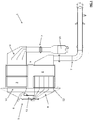
figure 1 , depicting in a schematic and exemplary manner a section of a sterilization system according to the invention. With reference to attachedfigure 1 , with thenumeral reference 1 has been depicted a sterilization system for a machine for the production of aseptic containers according to the present invention. - The
system 1 comprises: anairflow inlet section 2 for the entrance of an airflow; afirst filtering group 3 disposed downstream with respect to theairflow inlet section 2 and communicating with the latter for receiving the airflow; and asecond filtering group 4 disposed downstream with respect to thefirst filtering group 3 for receiving the airflow exiting from thefirst filtering group 3. - The
system 1 further comprises: a connection zone 5 connecting thefirst filtering group 3 to thesecond filtering group 4; supplyingmeans 6 for supplying a sterilization substance; and an airflow exiting section 7 disposed downstream with respect to thesecond filtering group 4 and communicating with the latter for allowing the exit of the airflow containing the sterilization substance. - In particular, the connection zone 5 defines an airflow passage conduit comprising: a
first section 51 communicating with thefirst filtering group 3; asecond section 52 communicating with thesecond filtering group 4; and athird section 53 interposed between thefirst section 51 and thesecond section 52; in detail, thethird section 53 is smaller than thefirst section 51 and thesecond section 52. In other words, the airflow passage conduit defined by the connection zone 5 has a constriction along the relative development (indeed, at the mentioned third section 53). - Furthermore, the supplying means 6 (e.g. supplying nozzles/injectors) are designed for supplying the sterilization substance at the
third section 53 of the connection zone 5 (i.e. in the part interested by the mentioned constriction), optimizing the sterilization substance distribution in the airflow. - Advantageously, the
sterilization system 1 according to the invention allows a uniform distribution of the sterilization substance in the airflow. In fact, the connection zone 5 defines an airflow passage conduit along which the airflow exiting from the first air-filtering group 3 is intended to pass, i.e. it defines a path for the airflow itself. - Along such a path, and in particular at the
third section 53 of the connection zone 5, constricted with respect to thefirst section 51 and thesecond section 52 among which is interposed, the sterilization substance is supplied. Consequently, advantageously, the supply of the sterilization substance is necessarily taking place in the airflow uniformly, the latter inevitably passing at thethird section 53. - In other words, the shape of the airflow passage conduit formed by the connection zone 5 (i.e. the relative
first section 51,second section 52 and third section 53) is fluid-dynamically designed to optimize the uniform diffusion of the sterilization substance in the airflow. - According to a shown preferred embodiment, the
sterilization system 1 according to the invention further comprises afirst channel group 8 at the connection zone 5, to distribute the airflow containing the sterilization substance toward thesecond filtering group 4. - Advantageously, the
first channel group 8 optimizes the distribution of the sterilization substance, the latter being uniformly distributed in the airflow, toward thesecond filtering group 4. Thus, thefirst channel group 8 has the collector function. - The
system 1 can further comprise asecond channel group 9 disposed between theairflow inlet section 2 and thefirst filtering group 3, to distribute the airflow toward the first filtering group 3 (seefigure 1 attached). Such asecond channel group 9 optimizes the distribution of the airflow inside thefirst filtering group 3. - Preferably, the
first filtering group 3 and thesecond filtering group 4 are mutually aligned. - For example, with reference to the figure, the
first filtering group 3 and thesecond filtering group 4 are placed side by side one to other. Alternatively, thefirst filtering group 3 and thesecond filtering group 4 can be positioned in a different way. - In accordance with the depicted embodiment, the airflow passage conduit defined by the connection zone 5 substantially has a "C profile" development. Such a configuration ensures a particularly compact overall footprint to the
whole system 1. Furthermore, thesystem 1 can comprise: a fan (not shown) for feeding the airflow and disposed upstream with respect to theairflow inlet section 2; and aheater 10 interposed between the fan and theairflow inlet section 2, for heating the airflow fed by the fan so that the latter reaches the conditions suitable for sterilizing the packaging material band and for ensuring its drying. - Preferably, the
first filtering group 3 and/or thesecond filtering group 4 comprise a plurality of HEPA filters and/or ULPA filters (with high efficiency). - For example, the sterilization substance supplied by the supplying means 5 is hydrogen peroxide.
- The invention further relates to a machine (not shown) for producing aseptic containers, for example for pourable food products such as fruit juices, sauces of various kinds, etc.
- The machine comprises: a feeding station, which feeds a packaging material band, and a sterilization station disposed downstream with respect to the feeding station, in which the packaging material band is sterilized, the sterilization station comprising a
sterilization system 1 according to any one of the embodiments described above. The machine further comprises: at least a welding station disposed downstream with respect to the sterilization station, in which the packaging material band is closed to form a continuous tube of packaging material; and a filling station, in which the tube of packaging material is filled with a product.
Claims (9)
- A sterilization system (1) for an aseptic containers production machine, comprising:an airflow inlet section (2) for the entrance of an airflow;a first filtering group (3), disposed downstream with respect to the airflow inlet section (2) for receiving the airflow;a second filtering group (4), disposed downstream with respect to the first filtering group (3) for receiving the airflow exiting from the first filtering group (3);a connection zone (5), connecting the first filtering group (3) to the second filtering group (4);supplying means (6) for supplying a sterilization substance; andan airflow exiting section (7), disposed downstream with respect to the second filtering group (4) for allowing the exit of the airflow containing the sterilization substance;characterized in that :the connection zone (5) defines an airflow passage conduit comprising: a first section (51) communicating with the first filtering group (3); a second section (52) communicating with the second filtering group (4); and a third section (53) interposed between the first section (51) and the second section (52), and smaller than the first section (51) and the second section (52);and in that the supplying means (6) are designed for supplying the sterilization substance at the third section (53) of the connection zone (5), optimizing the sterilization substance distribution in the airflow.
- The sterilization system (1) according to claim 1, further comprising a first channel group (8) at the connection zone (5), to distribute the airflow containing the sterilization substance toward the second filtering group (4).
- The sterilization system (1) according to anyone of the preceding claims, further comprising a second channel group (9) disposed between the airflow inlet section (2) and the first filtering group (3), to distribute the airflow toward the first filtering group (3).
- The sterilization system (1) according to anyone of the preceding claims, in which the first filtering group (3) and the second filtering group (4) are mutually aligned.
- The sterilization system (1) according to the preceding claim, in which the airflow passage conduit defined by the connection zone substantially has a "C profile" development.
- The sterilization system (1) according to anyone of the preceding claims, further comprising: a fan, disposed upstream with respect to the airflow inlet section (2), for supplying the airflow; a heater (10) interposed between the fan and the airflow inlet section (2), for heating the airflow supplied by the fan.
- The sterilization system (1) according to anyone of the preceding claims, in which the first filtering group (3) and/or the second filtering group (4) comprises a plurality of HEPA filters and/or ULPA filters.
- The sterilization system (1) according to anyone of the preceding claims, in which the sterilization substance supplied by the supplying means (5) is hydrogen peroxide.
- A machine for producing aseptic containers comprising: a feeding station, which feeds a packaging material band; a sterilization station, disposed downstream with respect to the feeding station, in which the packaging material band is sterilized; said sterilization station comprising a sterilization system (1) according to anyone of the preceding claims; at least one welding station, disposed downstream with respect to the sterilization station, in which the packaging material band is closed to form a continuous tube of packaging material; and a filling station in which the tube of packaging material is filled with a product.
Applications Claiming Priority (1)
| Application Number | Priority Date | Filing Date | Title |
|---|---|---|---|
| IT102016000072033A IT201600072033A1 (en) | 2016-07-11 | 2016-07-11 | Sterilization system for a machine for the production of aseptic containers |
Publications (2)
| Publication Number | Publication Date |
|---|---|
| EP3272365A1 true EP3272365A1 (en) | 2018-01-24 |
| EP3272365B1 EP3272365B1 (en) | 2026-08-05 |
Family
ID=57610076
Family Applications (1)
| Application Number | Title | Priority Date | Filing Date |
|---|---|---|---|
| EP17180548.4A Active EP3272365B1 (en) | 2016-07-11 | 2017-07-10 | A sterilization system for an aseptic containers production machine |
Country Status (2)
| Country | Link |
|---|---|
| EP (1) | EP3272365B1 (en) |
| IT (1) | IT201600072033A1 (en) |
Citations (5)
| Publication number | Priority date | Publication date | Assignee | Title |
|---|---|---|---|---|
| EP0815919A2 (en) * | 1996-07-04 | 1998-01-07 | Shikoku Kakoki Co., Ltd. | Filter unit |
| WO2004016988A1 (en) * | 2002-08-16 | 2004-02-26 | Kim Lui So | Self-cleaning exhaust system and method |
| DE102007017750A1 (en) * | 2007-04-12 | 2008-10-16 | Katfil Gmbh | Method for filtering and moistening air comprises filtering out large particles, forming mist of hydrogen peroxide disinfectant solution and mixing it with air, decomposing peroxide, forming free radicals and decomposing unreacted peroxide |
| DE102007062475A1 (en) * | 2007-12-20 | 2009-06-25 | Adolf Kolbinger | Gas i.e. polluted air, purification device, for use in exhaust air system, has odor adsorber material introducing unit that introduces odor adsorber material in gas flow, and separation unit that separates solid and liquid from gas flow |
| EP3034151A1 (en) * | 2014-12-19 | 2016-06-22 | Sidel Participations, S.A.S. | An air filter unit |
-
2016
- 2016-07-11 IT IT102016000072033A patent/IT201600072033A1/en unknown
-
2017
- 2017-07-10 EP EP17180548.4A patent/EP3272365B1/en active Active
Patent Citations (5)
| Publication number | Priority date | Publication date | Assignee | Title |
|---|---|---|---|---|
| EP0815919A2 (en) * | 1996-07-04 | 1998-01-07 | Shikoku Kakoki Co., Ltd. | Filter unit |
| WO2004016988A1 (en) * | 2002-08-16 | 2004-02-26 | Kim Lui So | Self-cleaning exhaust system and method |
| DE102007017750A1 (en) * | 2007-04-12 | 2008-10-16 | Katfil Gmbh | Method for filtering and moistening air comprises filtering out large particles, forming mist of hydrogen peroxide disinfectant solution and mixing it with air, decomposing peroxide, forming free radicals and decomposing unreacted peroxide |
| DE102007062475A1 (en) * | 2007-12-20 | 2009-06-25 | Adolf Kolbinger | Gas i.e. polluted air, purification device, for use in exhaust air system, has odor adsorber material introducing unit that introduces odor adsorber material in gas flow, and separation unit that separates solid and liquid from gas flow |
| EP3034151A1 (en) * | 2014-12-19 | 2016-06-22 | Sidel Participations, S.A.S. | An air filter unit |
Also Published As
| Publication number | Publication date |
|---|---|
| IT201600072033A1 (en) | 2018-01-11 |
| EP3272365B1 (en) | 2026-08-05 |
Similar Documents
| Publication | Publication Date | Title |
|---|---|---|
| CN103842258B (en) | Packaging machine and method for producing hermetically sealed packages of food products from a web of packaging material | |
| EP2733076A1 (en) | Device and method for sealing and heat-shrinking a multi-pack wrapped in a sheet of heat-shrinkable material | |
| US10040586B2 (en) | Package grouping unit with package linear speed reduction | |
| KR101954374B1 (en) | Method for packaging products and packaging system for carrying out said method | |
| WO2018041908A3 (en) | Filling machine and method for the sterile filling of a food product that contains a main component and an additional component | |
| KR20180041143A (en) | A device, preferably a device for producing food for manufacturing beverages by infusion in each liquid | |
| CN100450871C (en) | Pipe filling machine and method for sealing pipe ends in the machine | |
| EP3110696A1 (en) | Device and method for producing portion packets of a smokeless tobacco product or non-tobacco snuff product | |
| KR20130019787A (en) | Paper cup automatic packing apparatus | |
| US20170029150A1 (en) | Thermo-forming packaging machine | |
| US20200391893A1 (en) | Machine for packaging soft products | |
| KR20170094841A (en) | Straw manufacturing system | |
| EP3915889B1 (en) | Packaging machine and method of packaging products | |
| EP3427757A2 (en) | A sterilization apparatus for sterilizing a web of packaging material and a sterilization method | |
| JP2024505771A (en) | Packaging machines and sterile chambers for packaging machines | |
| CN111757835B (en) | Device and method for sterilizing a web of packaging material | |
| US20160318638A1 (en) | Apparatus and Method of Using an Apparatus for Controlling a Film | |
| EP3363473B1 (en) | A sterilization system for a machine manufacturing containers for pourable foodstuffs | |
| CN114502470B (en) | Packaging machine for manufacturing filter bags with brewing products | |
| CN103635404B (en) | For transmitting the transport unit of the sealed packaging of pourable food and remove the method for the sealed packaging fallen down from transport unit | |
| IT201600072033A1 (en) | Sterilization system for a machine for the production of aseptic containers | |
| US7658272B2 (en) | Apparatus for removing objects advanced on a conveyor | |
| GB2626254A (en) | Foodstuff packaging system and method therefor | |
| EP3590883A1 (en) | Hot fluid supply conduit configured for drying of articles and sterilization unit comprising said conduit | |
| CN120024560A (en) | Plastic packaging material steam sterilization, molding and aseptic filling and sealing system and method |
Legal Events
| Date | Code | Title | Description |
|---|---|---|---|
| PUAI | Public reference made under article 153(3) epc to a published international application that has entered the european phase |
Free format text: ORIGINAL CODE: 0009012 |
|
| STAA | Information on the status of an ep patent application or granted ep patent |
Free format text: STATUS: THE APPLICATION HAS BEEN PUBLISHED |
|
| AK | Designated contracting states |
Kind code of ref document: A1 Designated state(s): AL AT BE BG CH CY CZ DE DK EE ES FI FR GB GR HR HU IE IS IT LI LT LU LV MC MK MT NL NO PL PT RO RS SE SI SK SM TR |
|
| AX | Request for extension of the european patent |
Extension state: BA ME |
|
| STAA | Information on the status of an ep patent application or granted ep patent |
Free format text: STATUS: REQUEST FOR EXAMINATION WAS MADE |
|
| 17P | Request for examination filed |
Effective date: 20180622 |
|
| RBV | Designated contracting states (corrected) |
Designated state(s): AL AT BE BG CH CY CZ DE DK EE ES FI FR GB GR HR HU IE IS IT LI LT LU LV MC MK MT NL NO PL PT RO RS SE SI SK SM TR |
|
| STAA | Information on the status of an ep patent application or granted ep patent |
Free format text: STATUS: EXAMINATION IS IN PROGRESS |
|
| 17Q | First examination report despatched |
Effective date: 20211222 |
|
| RAP1 | Party data changed (applicant data changed or rights of an application transferred) |
Owner name: IPI S.R.L. |
|
| GRAP | Despatch of communication of intention to grant a patent |
Free format text: ORIGINAL CODE: EPIDOSNIGR1 |
|
| STAA | Information on the status of an ep patent application or granted ep patent |
Free format text: STATUS: GRANT OF PATENT IS INTENDED |
|
| INTG | Intention to grant announced |
Effective date: 20260223 |
|
| GRAS | Grant fee paid |
Free format text: ORIGINAL CODE: EPIDOSNIGR3 |
|
| GRAA | (expected) grant |
Free format text: ORIGINAL CODE: 0009210 |
|
| STAA | Information on the status of an ep patent application or granted ep patent |
Free format text: STATUS: THE PATENT HAS BEEN GRANTED |
|
| AK | Designated contracting states |
Kind code of ref document: B1 Designated state(s): AL AT BE BG CH CY CZ DE DK EE ES FI FR GB GR HR HU IE IS IT LI LT LU LV MC MK MT NL NO PL PT RO RS SE SI SK SM TR |
|
| REG | Reference to a national code |
Ref country code: CH Ref legal event code: F10 Free format text: ST27 STATUS EVENT CODE: U-0-0-F10-F00 (AS PROVIDED BY THE NATIONAL OFFICE) Effective date: 20260805 Ref country code: GB Ref legal event code: FG4D |