EP3272318B1 - Stentabgabesystem mit pistolenförmigem handgriff - Google Patents
Stentabgabesystem mit pistolenförmigem handgriff Download PDFInfo
- Publication number
- EP3272318B1 EP3272318B1 EP17181299.3A EP17181299A EP3272318B1 EP 3272318 B1 EP3272318 B1 EP 3272318B1 EP 17181299 A EP17181299 A EP 17181299A EP 3272318 B1 EP3272318 B1 EP 3272318B1
- Authority
- EP
- European Patent Office
- Prior art keywords
- delivery device
- rack
- stent
- stent delivery
- actuator
- Prior art date
- Legal status (The legal status is an assumption and is not a legal conclusion. Google has not performed a legal analysis and makes no representation as to the accuracy of the status listed.)
- Active
Links
Images


Classifications
-
- A—HUMAN NECESSITIES
- A61—MEDICAL OR VETERINARY SCIENCE; HYGIENE
- A61F—FILTERS IMPLANTABLE INTO BLOOD VESSELS; PROSTHESES; DEVICES PROVIDING PATENCY TO, OR PREVENTING COLLAPSING OF, TUBULAR STRUCTURES OF THE BODY, e.g. STENTS; ORTHOPAEDIC, NURSING OR CONTRACEPTIVE DEVICES; FOMENTATION; TREATMENT OR PROTECTION OF EYES OR EARS; BANDAGES, DRESSINGS OR ABSORBENT PADS; FIRST-AID KITS
- A61F2/00—Filters implantable into blood vessels; Prostheses, i.e. artificial substitutes or replacements for parts of the body; Appliances for connecting them with the body; Devices providing patency to, or preventing collapsing of, tubular structures of the body, e.g. stents
- A61F2/95—Instruments specially adapted for placement or removal of stents or stent-grafts
- A61F2/962—Instruments specially adapted for placement or removal of stents or stent-grafts having an outer sleeve
- A61F2/966—Instruments specially adapted for placement or removal of stents or stent-grafts having an outer sleeve with relative longitudinal movement between outer sleeve and prosthesis, e.g. using a push rod
-
- A—HUMAN NECESSITIES
- A61—MEDICAL OR VETERINARY SCIENCE; HYGIENE
- A61F—FILTERS IMPLANTABLE INTO BLOOD VESSELS; PROSTHESES; DEVICES PROVIDING PATENCY TO, OR PREVENTING COLLAPSING OF, TUBULAR STRUCTURES OF THE BODY, e.g. STENTS; ORTHOPAEDIC, NURSING OR CONTRACEPTIVE DEVICES; FOMENTATION; TREATMENT OR PROTECTION OF EYES OR EARS; BANDAGES, DRESSINGS OR ABSORBENT PADS; FIRST-AID KITS
- A61F2/00—Filters implantable into blood vessels; Prostheses, i.e. artificial substitutes or replacements for parts of the body; Appliances for connecting them with the body; Devices providing patency to, or preventing collapsing of, tubular structures of the body, e.g. stents
- A61F2/82—Devices providing patency to, or preventing collapsing of, tubular structures of the body, e.g. stents
- A61F2/844—Devices providing patency to, or preventing collapsing of, tubular structures of the body, e.g. stents folded prior to deployment
-
- A—HUMAN NECESSITIES
- A61—MEDICAL OR VETERINARY SCIENCE; HYGIENE
- A61F—FILTERS IMPLANTABLE INTO BLOOD VESSELS; PROSTHESES; DEVICES PROVIDING PATENCY TO, OR PREVENTING COLLAPSING OF, TUBULAR STRUCTURES OF THE BODY, e.g. STENTS; ORTHOPAEDIC, NURSING OR CONTRACEPTIVE DEVICES; FOMENTATION; TREATMENT OR PROTECTION OF EYES OR EARS; BANDAGES, DRESSINGS OR ABSORBENT PADS; FIRST-AID KITS
- A61F2/00—Filters implantable into blood vessels; Prostheses, i.e. artificial substitutes or replacements for parts of the body; Appliances for connecting them with the body; Devices providing patency to, or preventing collapsing of, tubular structures of the body, e.g. stents
- A61F2/95—Instruments specially adapted for placement or removal of stents or stent-grafts
- A61F2/9517—Instruments specially adapted for placement or removal of stents or stent-grafts handle assemblies therefor
-
- A—HUMAN NECESSITIES
- A61—MEDICAL OR VETERINARY SCIENCE; HYGIENE
- A61F—FILTERS IMPLANTABLE INTO BLOOD VESSELS; PROSTHESES; DEVICES PROVIDING PATENCY TO, OR PREVENTING COLLAPSING OF, TUBULAR STRUCTURES OF THE BODY, e.g. STENTS; ORTHOPAEDIC, NURSING OR CONTRACEPTIVE DEVICES; FOMENTATION; TREATMENT OR PROTECTION OF EYES OR EARS; BANDAGES, DRESSINGS OR ABSORBENT PADS; FIRST-AID KITS
- A61F2/00—Filters implantable into blood vessels; Prostheses, i.e. artificial substitutes or replacements for parts of the body; Appliances for connecting them with the body; Devices providing patency to, or preventing collapsing of, tubular structures of the body, e.g. stents
- A61F2/95—Instruments specially adapted for placement or removal of stents or stent-grafts
- A61F2002/9505—Instruments specially adapted for placement or removal of stents or stent-grafts having retaining means other than an outer sleeve, e.g. male-female connector between stent and instrument
- A61F2002/9511—Instruments specially adapted for placement or removal of stents or stent-grafts having retaining means other than an outer sleeve, e.g. male-female connector between stent and instrument the retaining means being filaments or wires
-
- A—HUMAN NECESSITIES
- A61—MEDICAL OR VETERINARY SCIENCE; HYGIENE
- A61F—FILTERS IMPLANTABLE INTO BLOOD VESSELS; PROSTHESES; DEVICES PROVIDING PATENCY TO, OR PREVENTING COLLAPSING OF, TUBULAR STRUCTURES OF THE BODY, e.g. STENTS; ORTHOPAEDIC, NURSING OR CONTRACEPTIVE DEVICES; FOMENTATION; TREATMENT OR PROTECTION OF EYES OR EARS; BANDAGES, DRESSINGS OR ABSORBENT PADS; FIRST-AID KITS
- A61F2/00—Filters implantable into blood vessels; Prostheses, i.e. artificial substitutes or replacements for parts of the body; Appliances for connecting them with the body; Devices providing patency to, or preventing collapsing of, tubular structures of the body, e.g. stents
- A61F2/95—Instruments specially adapted for placement or removal of stents or stent-grafts
- A61F2/962—Instruments specially adapted for placement or removal of stents or stent-grafts having an outer sleeve
- A61F2/966—Instruments specially adapted for placement or removal of stents or stent-grafts having an outer sleeve with relative longitudinal movement between outer sleeve and prosthesis, e.g. using a push rod
- A61F2002/9665—Instruments specially adapted for placement or removal of stents or stent-grafts having an outer sleeve with relative longitudinal movement between outer sleeve and prosthesis, e.g. using a push rod with additional retaining means
Definitions
- the present disclosure relates generally to vascular intervention device delivery systems, and more particularly to a pistol shaped stent delivery device that utilizes a roller clutch in its mechanical linkage.
- Self expanding stents and similar vascular intervention devices are often delivered and deployed using so called pin and pull systems.
- the stent is compressed between a retractable outer sheath and an inner catheter.
- To deploy the stent the user has to pull the outer sheath to uncover the stent using one hand while resisting the force with the other hand on the inner catheter to maintain the position of the stent during deployment.
- the user can have difficultly maintaining the inner catheter at a fixed position while simultaneously moving the outer sheath. In very difficult stent deployments, which require a large amount of force by the user, this simultaneous push and pull may lead to inaccurate stent positioning, shortening or lengthening of the stent, or possibly even damage to the stent or target vessel.
- the delivery device comprises an introducer sheath that is capable of distally advancing relative to the endoprosthesis from a proximal end thereof.
- the device is also capable of resheathing over the prosthesis in a proximal direction.
- the device comprises a drive pulley that can engage a particular gear set to axially move the introducer sheath and proximally release the prosthesis.
- the drive pulley can also engage another gear set to resheath the introducer sheath and recapture the prosthesis.
- the present disclosure is directed toward one or more of the problems set forth above.
- An aspect of the invention provides a stent delivery device as set out in claim 1.
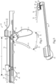
- a stent delivery device 10 includes a pistol shaped handle 11 with a barrel portion 12 extending atop a grip portion 13.
- a trigger actuator 14 is pivotably mounted to the pistol shaped handle 11 and defines an angle 15 with respect to the grip portion 13.
- a carrier 20 is slidably mounted to the barrel portion 12 of the pistol shaped handle 11.
- Carrier 20 may be connected to a retractable sheath 52 of a catheter assembly 50.
- the angle 15 is reduced responsive to pivoting the trigger actuator 14 in an actuation direction 16 toward the grip portion 13.
- the pistol shaped handle 11 may include a return spring 45 that biases trigger actuator 14 in the reset direction 17.
- Return spring 45 is shown in Figs. 2-4 as an elastic band stretched between pins attached to the handle 11 and trigger actuator 14, respectively.
- the roller clutch 40 is oriented in the mechanical linkage 30 to rotate responsive to the trigger actuator 14 pivoting in the reset direction 17, but the roller clutch 40 is held against rotation responsive to the trigger actuator 14 pivoting in the actuation direction 16.
- the roller clutch 40 is shown as attached to, and moving with, carrier 20, those skilled in the art will appreciate that the roller clutch 40 could be operably positioned elsewhere in the mechanical linkage 30 without departing from this disclosure.
- the mechanical linkage 30 may be an analog mechanical linkage such that the roller clutch 40 is not a ratchet.
- the carrier would only be able to move in increments associated with an integer number of teeth spacings 35 ( Fig. 2 ).
- roller clutch 40 may include a cam 41 positioned in a gear housing 42 ( Fig. 2 ).
- the carrier 20 is slidable and stoppable at any point in a continuum of distances 21 along the barrel portion 12. The carrier moves in proportion to a reduction of the angle 15 when the trigger actuator 14 is pivoted in the actuation direction 16.
- the mechanical linkage 30 may include a rack 32 with teeth 33 meshed with a pinion 34.
- the continuum of distances 21 includes movement distances that are less than a teeth spacing 35 of the rack 32.
- the teeth of gear housing 42 of roller clutch 40 are meshed with the teeth 33 of the rack 32.
- the mechanical linkage 30 may include a planetary gear assembly 36 in which the pinion 34 is attached to rotate with a sun gear 37 by way of a radial connection 39.
- the rack 32 moves fore and aft along barrel portion 12 of pistol shaped handle 11 responsive to pivoting the trigger actuator 14 in the reset direction 17 and the actuation direction 16, respectively.
- the trigger actuator 14 may rotate about an axis that is co-axial with sun gear 37.
- the trigger actuator 14 is attached to planetary gears 38 and 43 that are meshed with each other.
- planetary gear 38 is meshed with sun gear 37
- planetary gear 43 is meshed with the teeth of a partial ring gear 44 that is stationary and affixed to pistol shaped handle 11.
- the catheter assembly 50 which may be a portion stent delivery device 10, includes a catheter 51 attached in a fixed position to pistol shaped handle 11.
- a retractable sheath 52 is connected to move with the carrier 20 relative to the catheter 51.
- the retractable sheath 52 is movable from a first position 53 ( Fig. 11 ) covering a stent 55 that is supported on catheter 51 toward a second position 54 ( Fig. 14 ) uncovering, and out of contact with, the stent 55.
- the stent delivery device 10 may be equipped with a secondary actuator 60 in the event that the catheter assembly 50 includes one or more control wires to perform various functions during the deployment of stent 55.
- secondary actuator 60 is mounted to slide along the underside of barrel portion 12 between a first position 61 ( Fig. 14 ) and a second position 62 ( Fig. 15 ) to move a control wire (e.g., control wire 56).
- the secondary actuator 60 may include a secondary handle 63 that moves along a line parallel to barrel portion 12 from the first position 61 to the second position 62.
- the secondary actuator 60 may also include a clutched gear 64 that is remote from, but attached to move with, the secondary handle 63.
- Clutched gear 64 may be identical to the roller clutch 40 discussed earlier with regard to mechanical linkage 30, or may take the form of a ratchet without departing from the intended scope of the present disclosure.
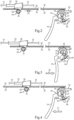
- Fig. 5 shows the secondary actuator 60 separated from pistol shaped handle 11, and the series of illustrations of Figs. 6-10 show the action of the secondary actuator 60 with several rack sliders 65, 73 and 75.
- a first control wire 56 may have one end 57 coupled to stent 55, such as for holding the one end of the stent 55 in close proximity to catheter 51.
- a second end 58 of control wire 56 may be attached to move with a rack slider 65 of secondary actuator 60.
- control wire 56 moves to release the one end of stent 55 as shown in Figs. 14 and 15 .
- Each of the rack sliders 65, 73 and 75 include teeth meshed with the teeth of clutched gear 64, which like roller gear 40 discussed earlier, only rotates in one direction.
- the teeth 66 of rack slider 65 and the teeth 67 of rack slider 73 may be configured to create a gear tooth interference stop 80 that prevents clutched gear 64 from rotating past rack slider 65 or the further most rack slider.
- the gear tooth interference stop 80 is created when any pair of rack sliders 65, 73 and 75 are abutting each other as shown in Fig. 6 , for instance.
- a secondary rack slider 73 is used in conjunction with a second control wire 70.
- one end 71 of the second control wire 70 may be coupled to stent 55, such as for holding the opposite end of the stent 55 in close proximity to catheter 51 during the deployment procedure.
- An opposite end 72 of the control wire 70 is connected to move with rack slider 73 under the action of secondary actuator 60 as illustrated in Figs. 9-10 and 16-17.
- the trigger actuator 14, the mechanical linkage 30 and the carrier 20 are responsible for taking human input and transferring it to a linear force needed to un-sheath a stent for deployment.
- the planetary gear assembly 36 is sometimes known as a reversing planetary gear set which takes the rotation of the trigger actuator 14 and converts it to linear motion by way of the gears 34, 37, 38, 40, 43, 44 and rack 32 of the mechanical linkage 30.
- the gear rack 32 is coupled with the carrier 20 via a roller clutch 40 as described previously.
- the trigger actuator 14 is moved in the actuation direction 16 by the user and is moved back to its original position via a reset direction 17 by a return spring 45.
- Each pull of the trigger actuator 14 retracts the carrier 20 and hence the retractable sheath 52 a limited distance that is governed, by among other things, the angular displacement of the sun gear 37, the angular displacement of the planetary gears 38 and 43, the number of teeth on the sun gear 37 and the number of teeth on the ring gear 44.
- the angular displacement of the sun gear 37 the angular displacement of the planetary gears 38 and 43
- the number of teeth on the sun gear 37 and the number of teeth on the ring gear 44.
- Those skilled in the art will appreciate that with appropriate design, one can engineer the relationship between how far the carrier 20 moves with each full pivoting action of trigger actuator 14. For instance, in the illustrated embodiment, one full pivoting of the trigger actuator 40 may yield about 40 millimeters of displacement for the gear rack 32 and carrier 20. Thus, for 120 millimeter stent graft, the total number of trigger pulls may be three or more.
- the roller clutch 40 on the carrier 20 allows for cyclical motion of the rack 32.
- the roller clutch 40 locks and pulls the carrier 20 with the rack 32.
- the trigger actuator 14 is pushed back toward its original position in the reset direction 17 by the return spring 45, the rack 32 moves forward to its original position because the roller clutch allows the gear housing 42 to spin in place, leaving its longitudinal position unchanged.
- the present disclosure finds general applicability to delivery systems for self expanding stents.
- the present disclosure finds specific applicability to converting a conventional two handed pin and pull stent deployment system into a single hand operation using a pistol grip.
- the present disclosure also finds specific applicability to stent delivery devices with the ability to move and stop the retractable sheath anywhere in a continuum of movement distances with precise control, while maintaining the built up tension in the system.
- the stent delivery system 10 includes a mechanical linkage 30 that includes a planetary gear assembly, the proportionality of how far carrier 20 moves responsive to each movement of trigger actuator 14 can be engineered to provide a mechanical advantage.
- the trigger actuator 14 may have to be moved between one and multiple times in the actuation direction 16 to completely uncover a stent 55 depending upon a specific application.
- the stent delivery device 10 may be equipped with a feature that prevents secondary actuator 60 from moving away from its first position 61 until after the carrier 20 has been moved sufficiently far to completely uncover stent 55.
- One major clinical advantage of the presently disclosed stent delivery device over currently available pin and pull systems is the stability, hand positioning and visual reference available in a pistol-grip style delivery system.
- sheath 52 retraction can be performed with one hand while maintaining system stability.
- Another major advantage may be the ability of the practitioner to maintain hand position during tracking, placement and deployment, thus increasing the accuracy of placement and system usability.
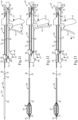
- FIG. 14 shows stent delivery device 10 in a pre-deployment configuration with carrier 20 positioned toward the remote end of barrel portion 12 of pistol shape handle 11 and with retractable sheath 50 in its first position 53 covering a stent 55, which is not visible in Fig. 11 .
- the secondary actuator 60 is shown in its first position, with control wires 56 and 70 not yet in play.
- a first control wire 56 is used for releasing the remote end of stent 55 and a second control wire 70 is used for releasing the near end of stent 55 using the secondary actuator 60.
- the secondary actuator 60 is moved along barrel portion 12 from the first position 61 to the second position 62 to pull control wire 56 in the direction away from stent 55 to release the remote end of the stent 55 as shown in Fig. 15 .
- the secondary actuator 60 is moved back to the first position to pick up the second rack slider 73 to operate second control wire 70.
- Fig. 16 This aspect is shown in Fig. 16 .
- the secondary actuator 60 again is moved from its first position 61 to its second position 62 shown in Fig. 17 to move the second rack slider 73 to pull control wire 70 to release the proximal end of stent 55 as shown in Fig. 17 .
- the stent 55 is completely deployed and the stent delivery device 10 may be moved away from stent 55 as shown in Fig. 18 .
- the operation of stent delivery device 10 may include pivoting the trigger actuator 14 of the pistol shaped handle 11 toward the grip portion 13 in the actuation direction 16 one or more times to fully retract the sheath 50 to uncover stent 55.
- an analog mechanical linkage 30 facilitated by roller clutch 40 interconnects the trigger actuator 14 to the carrier 20 by using the roller clutch 40.
- the carrier 20 may be slid along barrel portion 12 responsive to movement of the analog linkage mechanical linkage 30 and stop the carrier 20 anywhere within the continuum of distances 21 ( Fig. 1 ) responsive to stopping the trigger actuator 14.
- the trigger actuator may be pivoted in the reset direction 17, which is a direction opposite to actuation direction 16.
- the roller clutch 40 is held against rotation when the trigger actuator 14 is pivoted in the actuation direction 16 so as to move with rack 32, but the roller clutch rotates when the trigger actuator 14 is pivoted in the reset direction 17.
Landscapes
- Health & Medical Sciences (AREA)
- Engineering & Computer Science (AREA)
- Biomedical Technology (AREA)
- Cardiology (AREA)
- Oral & Maxillofacial Surgery (AREA)
- Transplantation (AREA)
- Heart & Thoracic Surgery (AREA)
- Vascular Medicine (AREA)
- Life Sciences & Earth Sciences (AREA)
- Animal Behavior & Ethology (AREA)
- General Health & Medical Sciences (AREA)
- Public Health (AREA)
- Veterinary Medicine (AREA)
- Media Introduction/Drainage Providing Device (AREA)
- Surgical Instruments (AREA)
Claims (13)
- Stentabgabevorrichtung (10), umfassend:einen pistolenförmigen Handgriff (11) mit einem Zylinderabschnitt (12), der sich oben auf einem Greifabschnitt (13) erstreckt,eine Auslösebetätigungseinrichtung (14), die schwenkbar an dem pistolenförmigen Handgriff befestigt ist und einen Winkel (15) mit Bezug auf den Greifabschnitt definiert,einen Träger (20), der verschiebbar an dem Zylinderabschnitt des pistolenförmigen Handgriffs befestigt ist,eine mechanische Verbindung (30), die eine Rollenkupplung (40) aufweist, die die Auslösebetätigungseinrichtung mit dem Träger verbindet,wobei der Winkel in Reaktion auf das Schwenken der Auslösebetätigungseinrichtung in eine Betätigungsrichtung in Richtung des Greifabschnitts verringert wird, und der Winkel in Reaktion auf das Schwenken des Auslöseelements in eine Zurücksetzrichtung vergrößert wird,wobei die Rollenkupplung in der mechanischen Verbindung ausgerichtet ist, um in Reaktion darauf zu drehen, dass der Auslöser in die Zurücksetzrichtung schwenkt, aber die Rollenkupplung in Reaktion darauf, dass der Auslöser in die Betätigungsrichtung schwenkt, gegen die Drehung hält.
- Stentabgabevorrichtung nach Anspruch 1, wobei die mechanische Verbindung (30) eine analoge mechanische Verbindung ist, und
der Träger (20) ein Kontinuum von Entfernungen entlang des Zylinderabschnitts proportional zu einer Verringerung des Winkels verschiebbar ist, wenn die Auslösebetätigungseinrichtung (14) in die Betätigungsrichtung geschwenkt wird. - Stentabgabevorrichtung (10) nach einem der Ansprüche 1-2, wobei die mechanische Verbindung (30) eine Zahnstange mit Zähnen aufweist, die mit einem Ritzel im Eingriff sind, und
das Kontinuum von Entfernungen eine Entfernung aufweist, die geringer ist als ein Abstand zwischen den Zähnen der Zahnstange. - Stentabgabevorrichtung (10) nach einem der Ansprüche 1-3, wobei die mechanische Verbindung (30) eine Planetenradanordnung aufweist, in der das Ritzel angebracht ist, um mit einem Sonnenrad zu drehen, und die Auslösebetätigungseinrichtung (14) an einem Planetenrad angebracht ist, dass mit dem Sonnenrad im Eingriff ist.
- Stentabgabevorrichtung (10) nach einem der Ansprüche 1-4, wobei die Rollenkupplung (40) einen Nocken aufweist, der in einem Getriebegehäuse positioniert ist, das mit einer Zahnstange im Eingriff ist, und der Träger (20) an dem Nocken angebracht ist.
- Stentabgabevorrichtung (10) nach einem vorhergehenden Anspruch, wobei die mechanische Verbindung (30) eine Zahnstange aufweist, die sich in Reaktion auf das Schwenken der Auslösebetätigungseinrichtung (14) in die Zurücksetzrichtung bzw. die Betätigungsrichtung entlang des Zylinderabschnitts vor und zurück bewegt.
- Stentabgabevorrichtung (10) nach einem vorhergehenden Anspruch mit einer Katheteranordnung (50), die einen Katheter (51) aufweist, der an dem pistolenförmigen Handgriff (11) angebracht ist, und einer zurückziehbaren Hülle (52), die verbunden ist, um sich bezogen auf den Katheter mit dem Träger zu bewegen, und
wobei die zurückziehbare Hülle aus einer ersten Position, in der sie einen an dem Katheter gelagerten Stent abdeckt, in eine zweite Position, in der sie den Stent freilegt und nicht mehr damit in Kontakt ist, beweglich ist. - Stentabgabevorrichtung (10) nach Anspruch 7, wobei die Katheteranordnung einen Steuerdraht aufweist,eine zweite Betätigungseinrichtung (60), die an dem pistolenförmigen Handgriff (11) montiert ist und mit Bezug darauf aus einer ersten Position in eine zweite Position beweglich ist,wobei ein Ende des Steuerdrahts mit dem Stent gekoppelt ist und ein gegenüberliegendes Ende verbunden ist, um sich mit der zweiten Betätigungseinrichtung (60) zu bewegen.
- Stentabgabevorrichtung (10) nach Anspruch 8, wobei die zweite Betätigungseinrichtung einen zweiten Handgriff (63) aufweist, der sich entlang einer Linie parallel zu dem Zylinderabschnitt aus der ersten Position in die zweite Position bewegt,die zweite Betätigungseinrichtung ebenfalls ein Kupplungszahnrad (64) aufweist, das angebracht ist, um sich mit dem zweiten Handgriff zu bewegen, unddie zweite Betätigungseinrichtung einen Zahnstangenschieber aufweist, der mit dem gegenüberliegenden Ende des Steuerdrahts verbunden ist und Zähne aufweist, die mit den Zähnen des Kupplungszahnrades im Eingriff sind.
- Stentabgabevorrichtung (10) nach einem der Ansprüche 8-9, wobei der Steuerdraht ein erster Steuerdraht ist und der Zahnstangenschieber (65) ein erster Zahnstangenschieber ist,
ein zweiter Steuerdraht, von dem ein Ende mit dem Stent gekoppelt und ein gegenüberliegendes Ende verbunden ist, um sich mit einem zweiten Zahnstangenschieber zu bewegen, der eine Position hat, die an den ersten Zahnstangenschieber grenzt. - Stentabgabevorrichtung (10) nach Anspruch 10, wobei der erste und der zweite Zahnstangenschieber geformt sind, um einen Verzahnungseingriffsstopp (80) bezogen auf das Kupplungszahnrad zu erzeugen, wenn sie aneinandergrenzen.
- Stentabgabevorrichtung (10) nach einem vorhergehenden Anspruch, aufweisend eine zweite Betätigungseinrichtung, die an den pistolenförmigen Handgriff (11) montiert und mit Bezug darauf aus einer ersten Position in eine zweite Position beweglich ist,die zweite Betätigungseinrichtung ein Kupplungszahnrad (64) aufweist, das angebracht ist, um sich mit einem zweiten Handgriff zu bewegen, unddie zweite Betätigungseinrichtung eine Vielzahl von Zahnstangenschiebern aufweist, die verschiebbar an dem pistolenförmigen Handgriff montiert sind, undeiner der Zahnstangenschieber (65) Zähne hat, die mit den Zähnen des Kupplungszahnrades im Eingriff sind.
- Stentabgabevorrichtung nach Anspruch 12, wobei die Vielzahl von Zahnstangenschiebern (65) einen ersten Zahnstangenschieber und einen zweiten Zahnstangenschieber aufweist, die geformt sind, um einen Verzahnungseingriffsstopp bezogen auf das Kupplungszahnrad (64) zu erzeugen, wenn sie aneinander grenzen.
Applications Claiming Priority (1)
| Application Number | Priority Date | Filing Date | Title |
|---|---|---|---|
| US201662363557P | 2016-07-18 | 2016-07-18 |
Publications (2)
| Publication Number | Publication Date |
|---|---|
| EP3272318A1 EP3272318A1 (de) | 2018-01-24 |
| EP3272318B1 true EP3272318B1 (de) | 2023-12-20 |
Family
ID=59350735
Family Applications (1)
| Application Number | Title | Priority Date | Filing Date |
|---|---|---|---|
| EP17181299.3A Active EP3272318B1 (de) | 2016-07-18 | 2017-07-13 | Stentabgabesystem mit pistolenförmigem handgriff |
Country Status (2)
| Country | Link |
|---|---|
| US (1) | US10307276B2 (de) |
| EP (1) | EP3272318B1 (de) |
Families Citing this family (19)
| Publication number | Priority date | Publication date | Assignee | Title |
|---|---|---|---|---|
| US7763063B2 (en) | 2003-09-03 | 2010-07-27 | Bolton Medical, Inc. | Self-aligning stent graft delivery system, kit, and method |
| US9364314B2 (en) | 2008-06-30 | 2016-06-14 | Bolton Medical, Inc. | Abdominal aortic aneurysms: systems and methods of use |
| US9439751B2 (en) | 2013-03-15 | 2016-09-13 | Bolton Medical, Inc. | Hemostasis valve and delivery systems |
| EP3215072B1 (de) * | 2014-11-04 | 2021-03-10 | Abbott Cardiovascular Systems Inc. | System zur freisetzung eines implantats |
| US10307276B2 (en) * | 2016-07-18 | 2019-06-04 | Cook Medical Technologies Llc | Pistol stent delivery device and method of operating same |
| US11141299B2 (en) | 2016-10-31 | 2021-10-12 | Cook Medical Technologies Llc | Suture esophageal stent introducer |
| US10500080B2 (en) * | 2016-10-31 | 2019-12-10 | Cook Medical Technologies Llc | Suture esophageal stent introducer |
| US11141298B2 (en) | 2016-10-31 | 2021-10-12 | Cook Medical Technologies Llc | Suture esophageal stent introducer |
| US10765545B2 (en) | 2016-10-31 | 2020-09-08 | Cook Medical Technologies Llc | Suture esophageal stent introducer |
| US10849775B2 (en) | 2016-10-31 | 2020-12-01 | Cook Medical Technologies Llc | Suture esophageal stent introducer parallel handle |
| US11413175B2 (en) | 2016-10-31 | 2022-08-16 | Cook Medical Technologies Llc | Tube and suture stent introducer system |
| US10702408B2 (en) | 2016-10-31 | 2020-07-07 | Cook Medical Technologies Llc | Suture esophageal stent introducer |
| US11246727B2 (en) | 2016-10-31 | 2022-02-15 | Cook Medical Technologies Llc | Suture esophageal stent introducer |
| EP3595596B1 (de) * | 2017-03-15 | 2023-09-06 | Merit Medical Systems, Inc. | Transluminale freisetzungsvorrichtungen sowie zugehörige kits |
| EP3697352A1 (de) * | 2018-02-15 | 2020-08-26 | Boston Scientific Scimed, Inc. | Vorrichtungen und verfahren zur kontrollierten freisetzung eines stents |
| WO2021262264A1 (en) * | 2020-06-24 | 2021-12-30 | Bolton Medical, Inc. | Anti-backspin component for vascular prosthesis delivery device |
| CN111839808B (zh) * | 2020-09-03 | 2024-08-16 | 感测(无锡)智能装备有限公司 | 一种血栓枪 |
| WO2023212361A1 (en) | 2022-04-29 | 2023-11-02 | inQB8 Medical Technologies, LLC | Systems, devices, and methods for controllably and selectively occluding, restricting, and diverting flow within a patient's vasculature |
| WO2025059537A1 (en) * | 2023-09-14 | 2025-03-20 | inQB8 Medical Technologies, LLC | Systems, devices, and methods for implanting and/or retrieving devices for controllable enhancement of diuresis |
Family Cites Families (18)
| Publication number | Priority date | Publication date | Assignee | Title |
|---|---|---|---|---|
| US5968052A (en) | 1996-11-27 | 1999-10-19 | Scimed Life Systems Inc. | Pull back stent delivery system with pistol grip retraction handle |
| US6004328A (en) | 1997-06-19 | 1999-12-21 | Solar; Ronald J. | Radially expandable intraluminal stent and delivery catheter therefore and method of using the same |
| US6527779B1 (en) | 2000-07-10 | 2003-03-04 | Endotex Interventional Systems, Inc. | Stent delivery device |
| US7052511B2 (en) | 2002-04-04 | 2006-05-30 | Scimed Life Systems, Inc. | Delivery system and method for deployment of foreshortening endoluminal devices |
| ITTO20030037A1 (it) * | 2003-01-24 | 2004-07-25 | Sorin Biomedica Cardio S P A Ora S Orin Biomedica | Dispositivo d'azionamento per cateteri. |
| US7326236B2 (en) * | 2003-12-23 | 2008-02-05 | Xtent, Inc. | Devices and methods for controlling and indicating the length of an interventional element |
| EP1981432B1 (de) | 2005-06-30 | 2012-10-03 | Abbott Laboratories | Abgabesystem für ein medizinprodukt |
| IL170698A (en) | 2005-09-06 | 2011-11-30 | Allium Ltd | System for delivering a medical device to a body location |
| GB0618516D0 (en) | 2006-09-20 | 2006-11-01 | Angiomed Ag | Hand-held actuator device |
| GB0713497D0 (en) | 2007-07-11 | 2007-08-22 | Angiomed Ag | Device for catheter sheath retraction |
| US20120172963A1 (en) | 2007-07-16 | 2012-07-05 | Michael Ryan | Delivery device |
| WO2011081997A1 (en) | 2009-12-30 | 2011-07-07 | Wilson-Cook Medical Inc. | Proximal release delivery device |
| CN102892389B (zh) * | 2010-05-14 | 2015-06-03 | 美敦力瓦斯科尔勒公司 | 用于假体递送系统的导管手柄 |
| US9662235B2 (en) * | 2012-04-04 | 2017-05-30 | Boston Scientific Scimed, Inc. | Handle for delivering medical device |
| US9539130B2 (en) | 2012-10-29 | 2017-01-10 | Cook Medical Technologies Llc | Low profile stepped delivery system |
| US20150094794A1 (en) | 2013-10-01 | 2015-04-02 | Cook Medical Technologies Llc | Wire collection device with increasing collection diameter |
| EP3215072B1 (de) | 2014-11-04 | 2021-03-10 | Abbott Cardiovascular Systems Inc. | System zur freisetzung eines implantats |
| US10307276B2 (en) * | 2016-07-18 | 2019-06-04 | Cook Medical Technologies Llc | Pistol stent delivery device and method of operating same |
-
2017
- 2017-04-10 US US15/483,428 patent/US10307276B2/en active Active
- 2017-07-13 EP EP17181299.3A patent/EP3272318B1/de active Active
Also Published As
| Publication number | Publication date |
|---|---|
| US20180014954A1 (en) | 2018-01-18 |
| US10307276B2 (en) | 2019-06-04 |
| EP3272318A1 (de) | 2018-01-24 |
Similar Documents
| Publication | Publication Date | Title |
|---|---|---|
| EP3272318B1 (de) | Stentabgabesystem mit pistolenförmigem handgriff | |
| US9149379B2 (en) | Delivery device | |
| US20120172963A1 (en) | Delivery device | |
| US8414636B2 (en) | Introducer with ratchet handle drive | |
| EP2833846B1 (de) | Griff zur freisetzung einer medizinischen vorrichtung | |
| US10390949B2 (en) | Staged deployment devices and methods for transcatheter heart valve delivery systems | |
| US8986363B2 (en) | Proximal release delivery system | |
| US10820995B2 (en) | Inversion delivery device and method for a prosthesis | |
| US8075607B2 (en) | Control handle | |
| EP3028680B1 (de) | Griffanordnung einer ausgabevorrichtung zum sequentiellen einsetzen einer prothese | |
| US9308108B2 (en) | Controlled release and recapture stent-deployment device | |
| WO2013154749A1 (en) | Vascular prosthetic delivery device and method of use | |
| EP2598086A1 (de) | Protheseneinsetzungssystem mit gesteuerter freisetzung und retraktion | |
| CA2478474A1 (en) | Delivery system and method for deployment of foreshortening endoluminal devices | |
| EP2777646B1 (de) | Stent-Einführungsvorrichtung mit gesteuerter Freisetzung und Rückgewinnung |
Legal Events
| Date | Code | Title | Description |
|---|---|---|---|
| PUAI | Public reference made under article 153(3) epc to a published international application that has entered the european phase |
Free format text: ORIGINAL CODE: 0009012 |
|
| STAA | Information on the status of an ep patent application or granted ep patent |
Free format text: STATUS: THE APPLICATION HAS BEEN PUBLISHED |
|
| AK | Designated contracting states |
Kind code of ref document: A1 Designated state(s): AL AT BE BG CH CY CZ DE DK EE ES FI FR GB GR HR HU IE IS IT LI LT LU LV MC MK MT NL NO PL PT RO RS SE SI SK SM TR |
|
| AX | Request for extension of the european patent |
Extension state: BA ME |
|
| STAA | Information on the status of an ep patent application or granted ep patent |
Free format text: STATUS: REQUEST FOR EXAMINATION WAS MADE |
|
| 17P | Request for examination filed |
Effective date: 20180724 |
|
| RBV | Designated contracting states (corrected) |
Designated state(s): AL AT BE BG CH CY CZ DE DK EE ES FI FR GB GR HR HU IE IS IT LI LT LU LV MC MK MT NL NO PL PT RO RS SE SI SK SM TR |
|
| STAA | Information on the status of an ep patent application or granted ep patent |
Free format text: STATUS: EXAMINATION IS IN PROGRESS |
|
| 17Q | First examination report despatched |
Effective date: 20200311 |
|
| GRAP | Despatch of communication of intention to grant a patent |
Free format text: ORIGINAL CODE: EPIDOSNIGR1 |
|
| STAA | Information on the status of an ep patent application or granted ep patent |
Free format text: STATUS: GRANT OF PATENT IS INTENDED |
|
| RIC1 | Information provided on ipc code assigned before grant |
Ipc: A61F 2/95 20130101ALI20230629BHEP Ipc: A61F 2/966 20130101AFI20230629BHEP |
|
| INTG | Intention to grant announced |
Effective date: 20230712 |
|
| GRAS | Grant fee paid |
Free format text: ORIGINAL CODE: EPIDOSNIGR3 |
|
| GRAA | (expected) grant |
Free format text: ORIGINAL CODE: 0009210 |
|
| STAA | Information on the status of an ep patent application or granted ep patent |
Free format text: STATUS: THE PATENT HAS BEEN GRANTED |
|
| P01 | Opt-out of the competence of the unified patent court (upc) registered |
Effective date: 20231108 |
|
| AK | Designated contracting states |
Kind code of ref document: B1 Designated state(s): AL AT BE BG CH CY CZ DE DK EE ES FI FR GB GR HR HU IE IS IT LI LT LU LV MC MK MT NL NO PL PT RO RS SE SI SK SM TR |
|
| REG | Reference to a national code |
Ref country code: GB Ref legal event code: FG4D |
|
| REG | Reference to a national code |
Ref country code: CH Ref legal event code: EP |
|
| REG | Reference to a national code |
Ref country code: DE Ref legal event code: R096 Ref document number: 602017077644 Country of ref document: DE |
|
| REG | Reference to a national code |
Ref country code: IE Ref legal event code: FG4D |
|
| PG25 | Lapsed in a contracting state [announced via postgrant information from national office to epo] |
Ref country code: GR Free format text: LAPSE BECAUSE OF FAILURE TO SUBMIT A TRANSLATION OF THE DESCRIPTION OR TO PAY THE FEE WITHIN THE PRESCRIBED TIME-LIMIT Effective date: 20240321 |
|
| REG | Reference to a national code |
Ref country code: LT Ref legal event code: MG9D |
|
| PG25 | Lapsed in a contracting state [announced via postgrant information from national office to epo] |
Ref country code: LT Free format text: LAPSE BECAUSE OF FAILURE TO SUBMIT A TRANSLATION OF THE DESCRIPTION OR TO PAY THE FEE WITHIN THE PRESCRIBED TIME-LIMIT Effective date: 20231220 |
|
| REG | Reference to a national code |
Ref country code: NL Ref legal event code: MP Effective date: 20231220 |
|
| PG25 | Lapsed in a contracting state [announced via postgrant information from national office to epo] |
Ref country code: ES Free format text: LAPSE BECAUSE OF FAILURE TO SUBMIT A TRANSLATION OF THE DESCRIPTION OR TO PAY THE FEE WITHIN THE PRESCRIBED TIME-LIMIT Effective date: 20231220 |
|
| PG25 | Lapsed in a contracting state [announced via postgrant information from national office to epo] |
Ref country code: LT Free format text: LAPSE BECAUSE OF FAILURE TO SUBMIT A TRANSLATION OF THE DESCRIPTION OR TO PAY THE FEE WITHIN THE PRESCRIBED TIME-LIMIT Effective date: 20231220 Ref country code: GR Free format text: LAPSE BECAUSE OF FAILURE TO SUBMIT A TRANSLATION OF THE DESCRIPTION OR TO PAY THE FEE WITHIN THE PRESCRIBED TIME-LIMIT Effective date: 20240321 Ref country code: FI Free format text: LAPSE BECAUSE OF FAILURE TO SUBMIT A TRANSLATION OF THE DESCRIPTION OR TO PAY THE FEE WITHIN THE PRESCRIBED TIME-LIMIT Effective date: 20231220 Ref country code: ES Free format text: LAPSE BECAUSE OF FAILURE TO SUBMIT A TRANSLATION OF THE DESCRIPTION OR TO PAY THE FEE WITHIN THE PRESCRIBED TIME-LIMIT Effective date: 20231220 Ref country code: BG Free format text: LAPSE BECAUSE OF FAILURE TO SUBMIT A TRANSLATION OF THE DESCRIPTION OR TO PAY THE FEE WITHIN THE PRESCRIBED TIME-LIMIT Effective date: 20240320 |
|
| REG | Reference to a national code |
Ref country code: AT Ref legal event code: MK05 Ref document number: 1641854 Country of ref document: AT Kind code of ref document: T Effective date: 20231220 |
|
| PG25 | Lapsed in a contracting state [announced via postgrant information from national office to epo] |
Ref country code: NL Free format text: LAPSE BECAUSE OF FAILURE TO SUBMIT A TRANSLATION OF THE DESCRIPTION OR TO PAY THE FEE WITHIN THE PRESCRIBED TIME-LIMIT Effective date: 20231220 |
|
| PG25 | Lapsed in a contracting state [announced via postgrant information from national office to epo] |
Ref country code: SE Free format text: LAPSE BECAUSE OF FAILURE TO SUBMIT A TRANSLATION OF THE DESCRIPTION OR TO PAY THE FEE WITHIN THE PRESCRIBED TIME-LIMIT Effective date: 20231220 Ref country code: RS Free format text: LAPSE BECAUSE OF FAILURE TO SUBMIT A TRANSLATION OF THE DESCRIPTION OR TO PAY THE FEE WITHIN THE PRESCRIBED TIME-LIMIT Effective date: 20231220 Ref country code: NO Free format text: LAPSE BECAUSE OF FAILURE TO SUBMIT A TRANSLATION OF THE DESCRIPTION OR TO PAY THE FEE WITHIN THE PRESCRIBED TIME-LIMIT Effective date: 20240320 Ref country code: NL Free format text: LAPSE BECAUSE OF FAILURE TO SUBMIT A TRANSLATION OF THE DESCRIPTION OR TO PAY THE FEE WITHIN THE PRESCRIBED TIME-LIMIT Effective date: 20231220 Ref country code: LV Free format text: LAPSE BECAUSE OF FAILURE TO SUBMIT A TRANSLATION OF THE DESCRIPTION OR TO PAY THE FEE WITHIN THE PRESCRIBED TIME-LIMIT Effective date: 20231220 Ref country code: HR Free format text: LAPSE BECAUSE OF FAILURE TO SUBMIT A TRANSLATION OF THE DESCRIPTION OR TO PAY THE FEE WITHIN THE PRESCRIBED TIME-LIMIT Effective date: 20231220 |
|
| PG25 | Lapsed in a contracting state [announced via postgrant information from national office to epo] |
Ref country code: IS Free format text: LAPSE BECAUSE OF FAILURE TO SUBMIT A TRANSLATION OF THE DESCRIPTION OR TO PAY THE FEE WITHIN THE PRESCRIBED TIME-LIMIT Effective date: 20240420 |
|
| PG25 | Lapsed in a contracting state [announced via postgrant information from national office to epo] |
Ref country code: AT Free format text: LAPSE BECAUSE OF FAILURE TO SUBMIT A TRANSLATION OF THE DESCRIPTION OR TO PAY THE FEE WITHIN THE PRESCRIBED TIME-LIMIT Effective date: 20231220 Ref country code: CZ Free format text: LAPSE BECAUSE OF FAILURE TO SUBMIT A TRANSLATION OF THE DESCRIPTION OR TO PAY THE FEE WITHIN THE PRESCRIBED TIME-LIMIT Effective date: 20231220 |
|
| PG25 | Lapsed in a contracting state [announced via postgrant information from national office to epo] |
Ref country code: SK Free format text: LAPSE BECAUSE OF FAILURE TO SUBMIT A TRANSLATION OF THE DESCRIPTION OR TO PAY THE FEE WITHIN THE PRESCRIBED TIME-LIMIT Effective date: 20231220 |
|
| PG25 | Lapsed in a contracting state [announced via postgrant information from national office to epo] |
Ref country code: SM Free format text: LAPSE BECAUSE OF FAILURE TO SUBMIT A TRANSLATION OF THE DESCRIPTION OR TO PAY THE FEE WITHIN THE PRESCRIBED TIME-LIMIT Effective date: 20231220 Ref country code: SK Free format text: LAPSE BECAUSE OF FAILURE TO SUBMIT A TRANSLATION OF THE DESCRIPTION OR TO PAY THE FEE WITHIN THE PRESCRIBED TIME-LIMIT Effective date: 20231220 Ref country code: RO Free format text: LAPSE BECAUSE OF FAILURE TO SUBMIT A TRANSLATION OF THE DESCRIPTION OR TO PAY THE FEE WITHIN THE PRESCRIBED TIME-LIMIT Effective date: 20231220 Ref country code: IT Free format text: LAPSE BECAUSE OF FAILURE TO SUBMIT A TRANSLATION OF THE DESCRIPTION OR TO PAY THE FEE WITHIN THE PRESCRIBED TIME-LIMIT Effective date: 20231220 Ref country code: IS Free format text: LAPSE BECAUSE OF FAILURE TO SUBMIT A TRANSLATION OF THE DESCRIPTION OR TO PAY THE FEE WITHIN THE PRESCRIBED TIME-LIMIT Effective date: 20240420 Ref country code: EE Free format text: LAPSE BECAUSE OF FAILURE TO SUBMIT A TRANSLATION OF THE DESCRIPTION OR TO PAY THE FEE WITHIN THE PRESCRIBED TIME-LIMIT Effective date: 20231220 Ref country code: CZ Free format text: LAPSE BECAUSE OF FAILURE TO SUBMIT A TRANSLATION OF THE DESCRIPTION OR TO PAY THE FEE WITHIN THE PRESCRIBED TIME-LIMIT Effective date: 20231220 Ref country code: AT Free format text: LAPSE BECAUSE OF FAILURE TO SUBMIT A TRANSLATION OF THE DESCRIPTION OR TO PAY THE FEE WITHIN THE PRESCRIBED TIME-LIMIT Effective date: 20231220 |
|
| PG25 | Lapsed in a contracting state [announced via postgrant information from national office to epo] |
Ref country code: PT Free format text: LAPSE BECAUSE OF FAILURE TO SUBMIT A TRANSLATION OF THE DESCRIPTION OR TO PAY THE FEE WITHIN THE PRESCRIBED TIME-LIMIT Effective date: 20240422 Ref country code: PL Free format text: LAPSE BECAUSE OF FAILURE TO SUBMIT A TRANSLATION OF THE DESCRIPTION OR TO PAY THE FEE WITHIN THE PRESCRIBED TIME-LIMIT Effective date: 20231220 |
|
| REG | Reference to a national code |
Ref country code: DE Ref legal event code: R097 Ref document number: 602017077644 Country of ref document: DE |
|
| PG25 | Lapsed in a contracting state [announced via postgrant information from national office to epo] |
Ref country code: DK Free format text: LAPSE BECAUSE OF FAILURE TO SUBMIT A TRANSLATION OF THE DESCRIPTION OR TO PAY THE FEE WITHIN THE PRESCRIBED TIME-LIMIT Effective date: 20231220 |
|
| PLBE | No opposition filed within time limit |
Free format text: ORIGINAL CODE: 0009261 |
|
| STAA | Information on the status of an ep patent application or granted ep patent |
Free format text: STATUS: NO OPPOSITION FILED WITHIN TIME LIMIT |
|
| PG25 | Lapsed in a contracting state [announced via postgrant information from national office to epo] |
Ref country code: SI Free format text: LAPSE BECAUSE OF FAILURE TO SUBMIT A TRANSLATION OF THE DESCRIPTION OR TO PAY THE FEE WITHIN THE PRESCRIBED TIME-LIMIT Effective date: 20231220 |
|
| PG25 | Lapsed in a contracting state [announced via postgrant information from national office to epo] |
Ref country code: SI Free format text: LAPSE BECAUSE OF FAILURE TO SUBMIT A TRANSLATION OF THE DESCRIPTION OR TO PAY THE FEE WITHIN THE PRESCRIBED TIME-LIMIT Effective date: 20231220 Ref country code: DK Free format text: LAPSE BECAUSE OF FAILURE TO SUBMIT A TRANSLATION OF THE DESCRIPTION OR TO PAY THE FEE WITHIN THE PRESCRIBED TIME-LIMIT Effective date: 20231220 |
|
| 26N | No opposition filed |
Effective date: 20240923 |
|
| PG25 | Lapsed in a contracting state [announced via postgrant information from national office to epo] |
Ref country code: MC Free format text: LAPSE BECAUSE OF FAILURE TO SUBMIT A TRANSLATION OF THE DESCRIPTION OR TO PAY THE FEE WITHIN THE PRESCRIBED TIME-LIMIT Effective date: 20231220 |
|
| REG | Reference to a national code |
Ref country code: CH Ref legal event code: PL |
|
| PG25 | Lapsed in a contracting state [announced via postgrant information from national office to epo] |
Ref country code: LU Free format text: LAPSE BECAUSE OF NON-PAYMENT OF DUE FEES Effective date: 20240713 |
|
| PG25 | Lapsed in a contracting state [announced via postgrant information from national office to epo] |
Ref country code: LU Free format text: LAPSE BECAUSE OF NON-PAYMENT OF DUE FEES Effective date: 20240713 |
|
| PG25 | Lapsed in a contracting state [announced via postgrant information from national office to epo] |
Ref country code: CH Free format text: LAPSE BECAUSE OF NON-PAYMENT OF DUE FEES Effective date: 20240731 Ref country code: BE Free format text: LAPSE BECAUSE OF NON-PAYMENT OF DUE FEES Effective date: 20240731 |
|
| PG25 | Lapsed in a contracting state [announced via postgrant information from national office to epo] |
Ref country code: FR Free format text: LAPSE BECAUSE OF NON-PAYMENT OF DUE FEES Effective date: 20240731 |
|
| REG | Reference to a national code |
Ref country code: BE Ref legal event code: MM Effective date: 20240731 |
|
| PGFP | Annual fee paid to national office [announced via postgrant information from national office to epo] |
Ref country code: DE Payment date: 20250728 Year of fee payment: 9 |
|
| PGFP | Annual fee paid to national office [announced via postgrant information from national office to epo] |
Ref country code: GB Payment date: 20250722 Year of fee payment: 9 |
|
| PGFP | Annual fee paid to national office [announced via postgrant information from national office to epo] |
Ref country code: IE Payment date: 20250718 Year of fee payment: 9 |
|
| PG25 | Lapsed in a contracting state [announced via postgrant information from national office to epo] |
Ref country code: CY Free format text: LAPSE BECAUSE OF FAILURE TO SUBMIT A TRANSLATION OF THE DESCRIPTION OR TO PAY THE FEE WITHIN THE PRESCRIBED TIME-LIMIT; INVALID AB INITIO Effective date: 20170713 |
|
| PG25 | Lapsed in a contracting state [announced via postgrant information from national office to epo] |
Ref country code: HU Free format text: LAPSE BECAUSE OF FAILURE TO SUBMIT A TRANSLATION OF THE DESCRIPTION OR TO PAY THE FEE WITHIN THE PRESCRIBED TIME-LIMIT; INVALID AB INITIO Effective date: 20170713 |