EP3272271B1 - Adaptive laryngoscope and adaptive spatula for a laryngoscope - Google Patents
Adaptive laryngoscope and adaptive spatula for a laryngoscope Download PDFInfo
- Publication number
- EP3272271B1 EP3272271B1 EP17182098.8A EP17182098A EP3272271B1 EP 3272271 B1 EP3272271 B1 EP 3272271B1 EP 17182098 A EP17182098 A EP 17182098A EP 3272271 B1 EP3272271 B1 EP 3272271B1
- Authority
- EP
- European Patent Office
- Prior art keywords
- chain
- adaptive
- chain links
- spacer
- links
- Prior art date
- Legal status (The legal status is an assumption and is not a legal conclusion. Google has not performed a legal analysis and makes no representation as to the accuracy of the status listed.)
- Active
Links
- 230000003044 adaptive effect Effects 0.000 title claims description 157
- 125000006850 spacer group Chemical group 0.000 claims description 155
- 238000002627 tracheal intubation Methods 0.000 claims description 12
- 230000007423 decrease Effects 0.000 claims description 7
- 239000002184 metal Substances 0.000 claims description 6
- 239000000470 constituent Substances 0.000 claims 3
- 210000002105 tongue Anatomy 0.000 description 8
- 238000005096 rolling process Methods 0.000 description 7
- 238000003780 insertion Methods 0.000 description 6
- 230000037431 insertion Effects 0.000 description 6
- 238000009434 installation Methods 0.000 description 6
- 239000000463 material Substances 0.000 description 5
- 230000003247 decreasing effect Effects 0.000 description 4
- 238000001356 surgical procedure Methods 0.000 description 4
- 210000000867 larynx Anatomy 0.000 description 3
- 210000003484 anatomy Anatomy 0.000 description 2
- 230000008878 coupling Effects 0.000 description 2
- 238000010168 coupling process Methods 0.000 description 2
- 238000005859 coupling reaction Methods 0.000 description 2
- 239000003814 drug Substances 0.000 description 2
- 230000012447 hatching Effects 0.000 description 2
- 230000001954 sterilising effect Effects 0.000 description 2
- 238000004659 sterilization and disinfection Methods 0.000 description 2
- 206010002091 Anaesthesia Diseases 0.000 description 1
- 230000006978 adaptation Effects 0.000 description 1
- 230000037005 anaesthesia Effects 0.000 description 1
- 238000005520 cutting process Methods 0.000 description 1
- 230000001419 dependent effect Effects 0.000 description 1
- 238000011161 development Methods 0.000 description 1
- 230000018109 developmental process Effects 0.000 description 1
- 239000013013 elastic material Substances 0.000 description 1
- 229940124645 emergency medicine Drugs 0.000 description 1
- 230000007613 environmental effect Effects 0.000 description 1
- 239000012530 fluid Substances 0.000 description 1
- 239000011888 foil Substances 0.000 description 1
- 238000002576 laryngoscopy Methods 0.000 description 1
- 238000004519 manufacturing process Methods 0.000 description 1
- 238000007493 shaping process Methods 0.000 description 1
- 239000007787 solid Substances 0.000 description 1
- 238000003860 storage Methods 0.000 description 1
- 210000003437 trachea Anatomy 0.000 description 1
- 210000001260 vocal cord Anatomy 0.000 description 1
Images


Classifications
-
- A—HUMAN NECESSITIES
- A61—MEDICAL OR VETERINARY SCIENCE; HYGIENE
- A61B—DIAGNOSIS; SURGERY; IDENTIFICATION
- A61B1/00—Instruments for performing medical examinations of the interior of cavities or tubes of the body by visual or photographical inspection, e.g. endoscopes; Illuminating arrangements therefor
- A61B1/267—Instruments for performing medical examinations of the interior of cavities or tubes of the body by visual or photographical inspection, e.g. endoscopes; Illuminating arrangements therefor for the respiratory tract, e.g. laryngoscopes, bronchoscopes
-
- A—HUMAN NECESSITIES
- A61—MEDICAL OR VETERINARY SCIENCE; HYGIENE
- A61B—DIAGNOSIS; SURGERY; IDENTIFICATION
- A61B1/00—Instruments for performing medical examinations of the interior of cavities or tubes of the body by visual or photographical inspection, e.g. endoscopes; Illuminating arrangements therefor
- A61B1/005—Flexible endoscopes
- A61B1/0051—Flexible endoscopes with controlled bending of insertion part
- A61B1/0055—Constructional details of insertion parts, e.g. vertebral elements
Definitions
- the present invention relates to an adaptive laryngoscope, in particular an adaptive intubation laryngoscope or an adaptive laryngoscope for laryngoscopy, laryngeal surgery or other tasks within ear, nose and throat medicine or otino-rhino-laryngology.
- the present invention is also related to an adaptive blade for such a laryngoscope or for an intubation device.
- a laryngoscope is used to push the tongue forward or rostral.
- a laryngoscope generally comprises a more or less curved spatula, at the proximal end of which a handle is arranged at an approximately right angle.
- the spatula is usually interchangeable to allow adaptation to the patient's anatomy.
- An intubation set contains a large number of spatulas of different lengths and curvatures. Different designs are also available for different applications and / or different preferences of medical personnel, for example according to Macintosh, Miller, Dörges and McCoy, the latter with a movable distal end.
- a laryngoscope with a deformable distal end is also in WO 97/30626 (later also published as US 6,174,281 B1 ) described.
- the spatula 4 of the laryngoscope has a plurality of slits 40 in a central section 14.
- the slots 40 divide the central section 14 into segments 42 which are connected to one another only by narrow webs which act as solid-state joints.
- EP 1 040 999 A2 describes a component for absorbing forces, in which struts 11, 11a connect opposite regions of an outer skin 12, 12a with one another.
- EP 2 241 403 A1 describes a manipulator tool with two flexible cheeks 8, 10. The cheeks 8, 10 are directly connected to each other at the distal end 6 of the manipulator tool 1 and, moreover, by a plurality of hinge elements 20.
- the medical gripping tool 1 comprises several branches 1, each with two opposite cheeks, between which connecting elements run.
- An object of the present invention is to provide an improved adaptive spatula for a laryngoscope and an improved adaptive laryngoscope.
- An adaptive spatula for a laryngoscope comprises a proximal end, a distal end, a first chain, arranged between the proximal end and the distal end of the adaptive spatula, of a plurality of chain links, which are each articulated in pairs, one between the proximal end and the distal end of the adaptive spatula arranged second chain of a plurality of chain links, which are each articulated in pairs, and a spacer, wherein a first end of the spacer is articulated to one of the chain links of the first chain, with a second end of the spacer articulated one of the chain links of the second chain is connected, wherein one or more or all of the articulated connections between the chain links of the first chain, the chain links of the second chain and the spacer component comprise a form-fitting joint.
- the adaptive spatula is provided and designed in particular to form a laryngoscope that can be used for intubation or for microlarynx surgery or for other tasks within otino-rhino-laryngology.
- the proximal end of the adaptive spatula can be mechanically connected to a handle component permanently - in particular for the entire intended lifespan of the laryngoscope - and not non-destructively.
- a proximal end of the adaptive spatula can be designed partially or entirely in one piece with the handle component, for example as a cast part made from plastic, metal or another sufficiently elastic material.
- a coupling device for example in the form of a bayonet or bayonet connection, a screw connection, a latching connection
- a coupling device can be provided at the proximal end of the adaptive spatula for a one-time or repeatable and non-destructively releasable coupling with a handle component.
- the distal end of the adaptive spatula is particularly designed and designed for insertion into the throat and for approaching the larynx of a patient.
- the first chain and the second chain each connect, in particular directly or indirectly, the proximal end and the distal end of the adaptive spatula.
- the first chain and the second chain are in particular arranged approximately parallel, their distance decreasing from proximal to distal.
- the first chain is in particular provided and designed to lie against the tongue of a patient when the adaptive spatula is used as intended.
- the chain links of the first chain are in particular each wide and formed with a flat or smooth or largely smooth surface which is intended to rest on the tongue.
- the first chain comprises two, three, four, five, six or more chain links.
- the chain links of the first chain can be identical or similar to one another.
- the width of the chain links of the first chain decreases from proximal to distal.
- Each individual chain link of the first chain is particularly rigid in itself, i. H. with the forces and moments occurring when the adaptive spatula is to be used, it cannot be deformed, or cannot be deformed significantly.
- one or more chain links of the first chain can be flexible d. H. be designed to be elastically and / or plastically deformable in the case of the forces and moments occurring when the adaptive spatula is to be used.
- the second chain is provided, designed and arranged so that the intended use of the adaptive spatula does not lie against the patient's tongue.
- the number of chain links in the second chain corresponds in particular to the number of chain links in the first chain.
- Each individual chain link of the second chain is in particular stiff in itself, ie it cannot be deformed, or cannot be deformed significantly, with the forces and moments that occur during the intended use of the adaptive spatula.
- a chain link or a plurality of chain links of the second chain can be flexible, ie elastically and / or plastically deformable in the case of the forces and moments that occur when the adaptive spatula is to be used.
- the adaptive spatula can have one or more spacer components.
- the number of spacer components is as large as the number of articulated connections between adjacent chain links of the second chain and / or as large as the number of articulated connections between adjacent chain links of the first chain. If the adaptive spatula has a plurality of spacer components, these in particular have different lengths, the length of the spacer components decreasing from proximal to distal.
- the spacer or spacers can each be rigid, i.e. H. with the forces and moments occurring in the intended application not or not significantly deformable.
- the spacer or one or more of the spacers may be flexible, i.e. H. with the forces and moments occurring during the intended use of the adaptive spatula, be elastically and / or plastically deformable. Flexibility of one or more spacer components can limit the force that can be transmitted or exerted with the adaptive spatula.
- the first end of the spacer component or the first end of one of a plurality of spacer components is in particular directly or indirectly articulatedly connected to one end of a chain link of the first chain or to two adjacent ends of adjacent chain links of the first chain.
- the second end of the spacer component or the second end of one of a plurality of spacer components is in particular directly or indirectly articulatedly connected to one end of a chain link of the second chain or to two adjacent ends of two adjacent chain links of the second chain.
- the adaptive spatula can comprise two second chains, which are arranged essentially in parallel, but whose distance decreases, in particular, from proximal to distal.
- two spacer components are arranged in parallel or essentially in parallel, each connecting one or two chain links from each of the two second chains to opposite edges of the first chain.
- the two second chains and the spacer components as well as the first chain are in particular arranged mirror-symmetrically to a plane of symmetry. Orthogonal in a section plane to this plane of symmetry, the adaptive spatula has a substantially U-shaped cross section.
- the adaptive spatula can be designed asymmetrically with a second chain or with several second chains, so that it is not mirror-symmetrical to any plane.
- Positive joints are joints that are not based on the elasticity of a component or an area of a component (for example, a foil joint), but on the positive guidance of two components to one another.
- Positive joints include, in particular, rolling or sliding bearings, each with two corresponding bearing surfaces, which slide directly against one another or between which rolling elements are arranged.
- the use of one or more positive joints between chain links of the first chain and / or between chain links of the second chain and / or between the first end of a spacer component and one or more chain links of the first chain and / or between the second end of the spacer component and one or Several chain links of the second chain can allow low-play and low-friction articulated connection of components of the adaptive spatula.
- the spatula can thus be adaptive in a very precisely defined manner, that is to say adapt to the surface and the deformability of the anatomy of a patient. In contrast to a conventional adaptive spatula, which has only solid-state joints or integral joints, no compromises are required with regard to the material.
- the chain links and the spacer component or the spacer components can be formed from any materials, in particular also from very rigid materials with a high modulus of elasticity, from brittle materials and from materials with a low elastic limit.
- At least some of the articulated connections are formed by uniaxial swivel joints.
- a single-axis swivel joint is a joint that has only one degree of freedom and in which one of the two components connected to one another by the swivel joint is only pivotable about a predetermined pivot axis relative to the other component. This pivotability about the predetermined pivot axis is particularly limited to a predetermined angular range.
- all articulated connections of the adaptive spatula are formed by single-axis swivel joints.
- the predetermined pivot axes of all joints are in particular parallel to one another or intersect at one point.
- the pivot axes are in particular orthogonal to this plane of symmetry.
- an articulated connection between two adjacent chain links of the first chain comprises a form-fitting joint and an articulated connection between two adjacent chain links of the second chain comprises a form-fitting joint.
- a plurality of articulated connections between each two adjacent chain links of the first chain each comprise a positive link and a plurality of articulated connections between each two adjacent chain links of the second chain each comprise a positive link.
- a plurality of articulated connections between spacer components and chain links of the second chain each comprise a form-fitting joint.
- the form-fitting joint comprises, in particular, a shaft inserted into a bore in a predetermined chain link, the shaft being at least either non-positively in the by means of an interference fit Bore is held in the predetermined chain link or is connected to the predetermined chain link by a weld.
- a first chain link engages in a recess in a second chain link
- the form-fitting joint comprising a shaft inserted into a bore in the second chain link, the shaft passing through the recess in the second chain link and engages within the recess by the first chain link, wherein the shaft is at least either held non-positively in the bore in the second chain link by an interference fit or is connected to the second chain link by a weld seam.
- the predetermined chain link or the first chain link and the second chain link are in particular part of the first chain of the adaptive spatula.
- a joint on the second chain of the adaptive spatula can also be designed in this way.
- the shaft has, in particular, the shape of a pin which can be slightly conical at one end in order to simplify insertion into the bore when the adaptive spatula is being assembled.
- the bore is in particular a blind bore in the predetermined chain link or in the second chain link.
- the interference fit includes a portion or area of the bore in which the inner diameter of the bore prior to shaft insertion, i. H. in the mechanically stress-free state, is smaller than the outer diameter of the shaft in the corresponding area before insertion into the bore, d. H. in a mechanically stress-free state.
- the shaft is pressed into the bore, causing mechanical stresses in the shaft and in the vicinity of the bore.
- the resulting restoring forces hold the shaft non-positively or frictionally in the bore.
- the interference fit is in particular not close to an outer surface arranged the second chain link. Instead, the interference fit is in particular in an area of the bore that is spaced from the outer surface of the second chain link.
- the recess in the second chain link is arranged in particular between the open end and the closed end of the blind bore and the interference fit between the recess and the closed end of the blind bore.
- the interference fit can prevent dirt in the form of a fluid or a solid from entering the region of the blind bore between the recess and its closed end.
- a weld seam or another materially joined joint can additionally connect the shaft to the second chain link.
- a weld is provided in particular at the open end of the bore on an outer surface of the second chain link.
- the weld seam surrounds the end of the shaft in a circular manner.
- chain links of the first chain are in particular essentially plate-shaped with a rectangular or trapezoidal outline.
- all chain links of the first chain are each essentially plate-shaped with a rectangular or trapezoidal outline.
- a trapezoidal plan of plate-shaped chain links enables, for example, a width of the adaptive spatula that decreases from proximal to distal.
- At least either one chain link of the first chain or one chain link of the second chain or the spacer component have metal.
- all chain links of the first chain and / or all chain links of the second chain and / or all spacer components have metal.
- the use of metal can allow the individual chain links and spacer components to be very rigid, and thus a very defined deformability of the adaptive spatula, that is to say exclusively or almost exclusively by the articulated connections. This can allow more defined or better dosed and controlled application of force by medical personnel to the patient.
- An adaptive spatula as described here, in particular further comprises a multiple joint device, in which an articulated connection between two chain links of the first chain and an articulated connection between a chain link of the first chain and the spacer component is integrated.
- the multiple joint device is designed in particular with the described interference fit between a shaft and a bore into which the shaft is inserted.
- the articulated connection between two chain links of the first chain and the articulated connection between a chain link of the first chain and the spacer component are integrated into the multiple joint device within a small installation space.
- the volume of the installation space of the multiple joint device is in particular not greater or not significantly greater than the sum of the volumes of two individual simple joint devices.
- the multiple joint device comprises in particular two individual joints, namely a joint between two chain links of the first chain and a joint between a chain link of the first chain and the spacer component or a joint between the spacer component and a first chain link of the first chain and a joint between the spacer component and one second chain link of the first chain.
- a multiple joint device can be advantageous in terms of manufacturing costs, the required installation space, the adaptive function and the mechanical robustness.
- the multiple joint device comprises in particular a shaft or an axle journal with a first bearing surface and a second bearing surface, the first bearing surface and the second bearing surface being part of articulated connections of the spacer component with two chain links of the first chain, or wherein the first bearing surface is part of the articulated connection between two chain links of the first chain and the second bearing surface part of the articulated connection between one Chain link of the first chain and the spacer is.
- the multiple joint device in particular further comprises a third bearing surface corresponding to the first bearing surface, the first bearing surface and the third bearing surface sliding against one another or a plurality of rolling elements being arranged between the first bearing surface and the third bearing surface.
- the multiple joint device further comprises a fourth bearing surface corresponding to the second bearing surface, the second bearing surface and the fourth bearing surface sliding against one another or a plurality of rolling elements being arranged between the second bearing surface and the fourth bearing surface.
- the first bearing surface and the second bearing surface on the shaft or the axle journal of the multiple joint device can be aligned or merge into one another or can be formed by different partial regions of a circular cylindrical surface region of the shaft or the axle journal.
- the first bearing surface and the second bearing surface can be separated from one another, for example by a step, wherein the first bearing surface and the second bearing surface can have different radii of curvature.
- the shaft or the journal can be rigidly connected to a first of the chain links of the first chain.
- a third bearing surface corresponding to the first bearing surface is provided on a second chain link of the first chain and a fourth bearing surface corresponding to the second bearing surface is provided on the spacer component.
- the shaft or the journal can be rigidly connected to the spacer component.
- the third bearing surface corresponding to the first bearing surface is arranged on a first chain link of the first chain and the fourth bearing surface corresponding to the second bearing surface is arranged on a second chain link of the first chain.
- An adaptive spatula as described here, in particular further comprises a multiple joint device, in which an articulated connection between two chain links of the second chain and an articulated connection between a chain link of the second chain and the spacer component is integrated.
- the articulated connection between two chain links of the second chain and the articulated connection between a chain link of the second chain and the spacer component are integrated into the multiple joint device within a small installation space.
- the volume of the installation space of the multiple joint device is in particular not greater or not significantly greater than the sum of the volumes of two individual simple joint devices.
- the multiple joint device comprises in particular two individual joints, namely a joint between two chain links of the second chain and a joint between a chain link of the second chain and the spacer component or a joint between the spacer component and a first chain link of the second chain and a joint between the spacer component and one second chain link of the second chain.
- the multiple joint device comprises in particular a shaft or an axle journal or a pin with a first bearing surface and a second bearing surface, the first bearing surface and the second bearing surface being components of articulated connections of the spacer component with two chain links of the second Are chain, or wherein the first bearing surface is part of the articulated connection between two chain links of the second chain and the second bearing surface is part of the articulated connection between a chain link of the second chain and the spacer.
- the multiple joint device in particular further comprises a third bearing surface corresponding to the first bearing surface, the first bearing surface and the third bearing surface sliding against one another or a plurality of rolling elements being arranged between the first bearing surface and the third bearing surface.
- the multiple joint device in particular further comprises a fourth bearing surface corresponding to the second bearing surface, the slide the second bearing surface and the fourth bearing surface together or a plurality of rolling elements are arranged between the second bearing surface and the fourth bearing surface.
- the first bearing surface and the second bearing surface on the shaft or the axle journal of the multiple joint device can be aligned or merge into one another or can be formed by different partial areas of a circular cylindrical surface area of the shaft or the axle journal.
- the first bearing surface and the second bearing surface can be separated from one another, for example by a step, wherein the first bearing surface and the second bearing surface can have different radii of curvature.
- the shaft or the journal can be rigidly connected to a first of the chain links of the second chain.
- a third bearing surface corresponding to the first bearing surface is provided on a second chain link of the second chain and a fourth bearing surface corresponding to the second bearing surface is provided on the spacer component.
- the shaft or the journal can be rigidly connected to the spacer component.
- the third bearing surface corresponding to the first bearing surface is arranged on a first chain link of the second chain and the fourth bearing surface corresponding to the second bearing surface is arranged on a second chain link of the second chain.
- bearing surfaces on two different chain links and a bearing surface on the spacer component are arranged coaxially.
- the bearing surfaces on two different chain links and the bearing surface on the spacer component are in particular at least partially arranged one inside the other so that one bearing surface encloses the other two bearing surfaces.
- a first of the three bearing surfaces can enclose a second of the three bearing surfaces and can be enclosed by a third of the three bearing surfaces.
- a sleeve is provided, on the inner surface and on the outer surface of which a bearing surface is provided, with a shaft or a journal on another Chain link is guided in the sleeve and the sleeve is in turn guided in a bore on the spacer component.
- An adaptive spatula as described here, in particular further comprises corresponding stop surfaces on two chain links which are articulated to one another, the corresponding stop surfaces being arranged such that mechanical contact of the corresponding stop surfaces causes a pivoting movement of the chain links on which the corresponding stop surfaces are arranged, limited relative to each other.
- the corresponding stop surfaces are in particular integrated into an articulated connection between the two chain links or arranged in the immediate vicinity of the articulated connection between the chain links.
- the corresponding stop surfaces are provided in particular on two chain links of the first chain which are connected to one another in an articulated manner.
- An adaptive spatula as described here, in particular furthermore comprises corresponding stop surfaces on a predetermined chain link and on the spacer component, the corresponding stop surfaces being arranged such that mechanical contact of the corresponding stop surfaces limits a pivoting movement of the predetermined chain link relative to the spacer component.
- the predetermined chain link is either a chain link of the first chain or a chain link of the second chain.
- the predetermined chain link is in particular a chain link which is directly articulated to the spacer component.
- Corresponding stop surfaces that limit a pivoting movement can simplify or make the use of the adaptive spatula safer, in particular during insertion into the throat of a patient. Furthermore, a limitation of swivel movements by corresponding stop surfaces can prevent mechanical overloading of the adaptive spatula, as might otherwise occur in an extreme configuration of the adaptive spatula.
- An adaptive spatula as described here, in particular further comprises an elastic jacket component to protect the adaptive spatula from dirt and other environmental influences.
- An adaptive spatula as described here, in particular furthermore comprises a channel into which at least either an endoscope or a light source or another medical instrument can be inserted or arranged.
- the channel can consist of a plurality or a plurality of segments, each of which can be annular or tubular and / or can have a U-shaped cross section.
- each segment of the channel is arranged on a chain link or integrated into a chain link.
- spacer components of the adaptive spatula form a boundary of the channel that resembles a railing.
- An adaptive spatula as described here, in particular further comprises a handle component for holding and guiding the adaptive spatula.
- An adaptive spatula as described here, can be provided and designed for repeated use and repeated sterilization (in particular steam sterilization in an autoclave) or for single use and subsequent disposal.
- An adaptive laryngoscope or an adaptive intubation device comprises an adaptive spatula, as described here, and a handle component that is mechanically connectable or connected to the proximal end of the adaptive spatula.
- the adaptive laryngoscope is in particular an intubation laryngoscope and / or intended for use in microlarynx surgery or for other applications in otino-rhino-laryngology.
- FIG. 1 shows a schematic axonometric representation of an adaptive intubation laryngoscope 10 with a handle component 11 for manually holding and guiding the intubation laryngoscope 10.
- the adaptive intubation laryngoscope 10 comprises an adaptive spatula 20 with a proximal end 21 and a distal end 29.
- the adaptive spatula 20 has one distal end 29 towards decreasing cross-section.
- the proximal end 21 of the adaptive spatula 20 is mechanically connected to the handle component 11 such that the region of the adaptive spatula 20 adjoining the proximal end with the handle component 11 forms an angle of approximately 90 degrees (in the range between approximately 80 degrees and 120 degrees ) includes.
- the adaptive spatula comprises a proximal end piece 22, which forms the proximal end 21 of the adaptive spatula 20. Furthermore, the adaptive spatula comprises a distal end piece 28, which forms the distal end 29 of the adaptive spatula 20. Furthermore, the adaptive spatula 20 comprises a first chain 23 and two second chains 25, which extend from the proximal end piece 22 to the distal end piece 28 of the adaptive spatula 20.
- the first chain 23 comprises a plurality of chain links 30, 40.
- the chain links 30, 40 of the first chain 23 have slightly different dimensions in the example shown, but are largely similar for the rest. Accordingly, only two chain links 30, 40 of the first chain 23 are provided with reference numerals, for example.
- the chain links 30, 40 of the first chain 23 are connected to one another by positive joints, so that the distal end 32 of a chain link 30 is connected in an articulated manner to the proximal end 41 of the chain link 40 which adjoins the distal link.
- the extremely proximal chain link of the first chain 23 is also connected to the proximal end piece 22 of the adaptive spatula 20 by a positive joint.
- the extremely distal chain link of the first chain 23 is also connected to the distal end piece 28 of the adaptive spatula 20 by a positive joint.
- the chain links 30, 40 of the first chain 23 are each approximately or essentially plate-shaped. In the example shown, each chain link 30, 40 has a substantially trapezoidal outline. Each chain link 30, 40 has one of width decreasing proximally to distally. The width of each chain link 30 at its distal edge or end 32 corresponds to the width of the distally adjacent chain link 40 at its proximal end 41. The width of the first chain 23 thus decreases from proximal to distal.
- the widths of the proximal and distal end pieces 22, 28 of the adaptive spatula 20 are matched to the widths of the first chains 23 at their proximal and distal ends.
- the distal end piece 28 has a smaller width than the proximal end piece 22 of the adaptive spatula 20.
- Each of the two second chains 25 has a plurality of chain links 50, 60 which are articulated in pairs.
- the chain links 50, 60 of the second chains 25 are similar to one another or largely similar to one another. All chain links 50, 60 of a second chain 25 or all chain links 50, 60 of both second chains 25 can be identical to one another.
- Corresponding or opposing chain links 50, 60 of the second chains 25 are in particular identical or mirror-symmetrical to one another. Accordingly, in Fig. 1 only two of the chain links of the second chains 25 are provided with reference numerals by way of example.
- the chain links 50, 60 of the second chain 25 are connected to one another in pairs by form-fitting joints, so that the distal end 52 of a chain link 50 is connected in an articulated manner to the proximal end 61 of the chain link 60 which adjoins the distal link.
- the proximal ends of the extremely proximal chain links of the second chains 25 are each connected to the proximal end piece 22 of the adaptive spatula 20 by an interlocking joint.
- the distal ends of the extremely distal chain links of the second chains 25 are each connected to the distal end piece 28 of the adaptive spatula 20 by a positive joint.
- the adaptive spatula 20 further includes a plurality of spacer components 70.
- Each spacer component 70 has a first end 71 and a second end 72.
- the spacer components 70 largely resemble one another and differ from one another in particular by their lengths. Therefore, only one spacer component 70 is provided with reference numerals as an example.
- each spacer component 70 is connected to two adjacent chain links 30, 40 of the first chain 23 by a positive joint.
- the second end 72 of each spacer component 70 is connected to two adjacent chain links 50, 60 by one of the two second chains 25 by means of a positive joint.
- the first ends 71 of the spacer components 70 are each arranged close to the outer edges of the first chain 23.
- two spacer components 70 are arranged mirror-symmetrically to one another and parallel or essentially parallel to one another. Therefore, on each pair of parallel spacers 70, the width of the arrangement of the two second chains 25 substantially corresponds to the width of the first chain 23 on the same pair of spacers 70.
- Each spacer component 70 defines the distance of the distal end 32 of a first chain link 30 of the first chain 23 and the proximal end 41 of a second chain link 40 of the first chain 23 on the one hand from the distal end 52 of a first chain link 50 of the second chain 25 and the proximal end 61 of a second chain link 60 of the second chain 25 on the other hand. Since the lengths of the spacer components 70 decrease from proximal to distal, the distances between the first chain 23 and the second chains 25 also decrease from proximal to distal.
- the chain links 30, 40 of the first chain 23, the chain links 50, 60 of the second chain 25 and the spacer components 70 together have a shape with a substantially rectangular U-shaped cross section, the spacer components 70 and the second chains 25 not having closed side walls, but just form fences similar structures.
- a spatial area within the U-shaped cross section forms a channel 27 through which a light source, a camera, an endoscope or another medical instrument partially or completely passed through or in which a light source, a camera, an endoscope or another medical instrument can be arranged.
- FIG 2 shows a schematic representation of an adaptive spatula 20, which in some features, properties and functions of the adaptive spatula 20 is based on the Figure 1 laryngoscope shown is similar.
- the in Figure 2 The spatula 20 shown is provided and designed in particular for detachable or permanent mechanical connection to a handle component in order to form a laryngoscope.
- Figure 3 shows a further schematic illustration of the adaptive spatula 20 Figure 2 .
- the drawing level of the Figure 3 corresponds to the drawing level of Figure 2 .
- the adaptive spatula 20 is shown in a configuration or situation that differs from that in FIG Figure 2 shown situation differs.
- the configuration shown is created, for example, by shaping the adaptive spatula 20 onto the curved surface of a patient's tongue.
- Chain links 30, 40, 50, 60 give way in one direction in a central region of the chains 23, 25 (in Figure 3 : down), while the distal end piece 28 of the adaptive spatula 20 in the opposite direction (in Figure 3 : up) is pivoted.
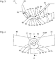
- Figure 4 shows a schematic representation of a part of an adaptive spatula, as it is based on the Figures 1 to 3 is described.
- the drawing level of the Figure 4 is parallel to the drawing levels of the Figures 2 and 3rd .
- Figure 4 the articulated connection between the distal end 32 of a first chain link 30, the proximal end 41 of a second chain link 40 and a first end 71 of a spacer component 70 is shown.
- the second chain link 40 partially covers the first chain link 30 and the spacer 70.
- Contours of the first chain link 30 and the spacer component 70, insofar as they are covered and therefore actually not visible, are indicated by dashed lines.
- others are in the view of Figure 4 structures that are actually not visible are indicated by dashed lines.
- the articulated connection of the chain links 30, 40 and the spacer component 70 takes place by means of a shaft 80 with a circular cylindrical cross section.
- the shaft 80 has an axis of symmetry 88 which forms the pivot axis of the articulated connection.
- the end of the shaft 80 facing the viewer is inserted into a corresponding bore in the second chain link 40 and joined to it in a friction and / or integral manner.
- Ring-shaped regions of the surface of the shaft 80 form bearing surfaces 83, 87.
- a bearing surface 78 which corresponds to the bearing surface 87 on the shaft 80, in particular opposite it.
- a stop surface 37 is provided on the first chain link 30.
- a first stop surface 73 corresponding to the stop surface 37 on the first chain link 30 is provided on the spacer component 70.
- a mechanical contact between the corresponding stop surfaces 37, 73 on the first chain link 30 and on the spacer component 70 limits a pivoting movement of the spacer component 70 relative to the first chain link 30.
- a stop surface 47 is provided on the second chain link 40.
- a second stop surface 74 corresponding to the stop surface 47 on the second chain link 40 is provided on the spacer component 70.
- a mechanical contact between the stop surfaces 47, 74 on the second chain link 40 and on the spacer component 70 limits a pivoting movement of the second chain link 40 relative to the spacer component 70.
- Figure 5 shows a schematic representation of a section along the in Figure 4 indicated section plane AA by the in Figure 4 shown articulated connection of the chain links 30, 40 and the spacer 70.
- the section plane AA of the Figure 5 is orthogonal to the plane of the drawing Figure 4 and includes the pivot axis and axis of symmetry 88 of the first shaft 80.
- the section plane AA of the Figure 5 intersects the distal end 32 of the first chain link 30, the proximal end 41 of the second chain link 40 and two spacer components 70.
- the chain links 30, 40 are mirror-symmetrical to a plane of symmetry that is orthogonal to the section plane AA Figure 5 and to the axis of symmetry 88 of the shaft 80.
- the spacer components 70 are arranged mirror-symmetrically to the same plane of symmetry. Therefore, reference numerals are only on one (in Figure 5 shown on the left).
- the proximal end 41 of the second chain link 40 has two recesses 44.
- the distal end 32 of the first chain link 30 is formed by two tongue-shaped or lamellar extensions which engage in the recesses 44 on the proximal end 41 of the second chain link 40.
- One end of a spacer component 70 also engages in each recess 44 in the proximal end 41 of the second chain link 40.
- the shaft 80 has little play and, in particular, is frictionally inserted into a corresponding bore in the proximal end 41 of the second chain link 40.
- the recesses 44 in the proximal end 41 of the second chain link 40 are arranged such that the shaft 80 penetrates both recesses 44. Portions of the outer surface of the shaft 80, which form the bearing surfaces 83, 87, are open in the recesses 44.
- the tongues or lamellae forming the distal end 32 of the first chain link 30 each have a bore through which the shaft 80 extends, and the inner surfaces of which form bearing surfaces 38 corresponding to the bearing surfaces 83 on the shaft 80.
- the ends 71 of the spacer components 70 each have a bore through which the shaft 80 extends, and the inner surfaces of which form bearing surfaces 78 corresponding to the bearing surfaces 87 on the shaft 80.
- the shaft 80 is rigidly connected to the proximal end 41 of the second chain link 40 and in this respect forms part of the second chain link 40.
- the bearing surfaces 38 on the distal end 32 of the first chain link 30 and the corresponding bearing surfaces 83 on the shaft 80 form a form-fitting joint between the first chain link 30 and the second chain link 40.
- the bearing surfaces 78 on the spacer components 70 and the corresponding bearing surfaces 87 on the shaft 80 form positive joints between the second chain link 40 and the spacer components 70.
- the areas of the shaft 80 within the recesses 44 in the proximal end 41 of the second chain link 40, the bearing surfaces 83, 87 located thereon and the corresponding bearing surfaces 38, 78 at the distal end 32 of the first chain link 30 and at the end 71 of the spacer component 70 form a multiple joint device.
- This multiple joint device combines positive joints between the two chain links 30, 40 and the spacer component 70 in a small installation space.
- Figure 6 shows a schematic representation of a section through an alternative embodiment of an articulated connection between chain links 30, 40 and a spacer component 70 of an adaptive spatula, as is shown in FIG Figures 1 to 3 is shown.
- the type of display, in particular the section plane, corresponds to that of Figure 5 .
- the embodiment shown is similar in some features, properties and functions to that shown in FIG Figures 4 and 5 illustrated design. In the following, features, properties and functions are described in particular, in which the in Figure 6 Shown embodiment differs from that based on the Figures 4 and 5 illustrated configuration differs.
- the shaft 80 is not rigidly connected to the second chain link 40. Rather, the shaft 80 and the corresponding bore in the proximal end 41 of the second chain link 40 are configured in such a way that the shaft 80 is not held in a frictionally engaged manner, but rather forms bearing surfaces 48. On the shaft 80 are corresponding to the bearing surfaces 48 at the proximal end 41 of the second chain link 40 Bearing surfaces 84 formed. In Figure 6 If a bearing clearance between the corresponding bearing surfaces 48, 84 indicates that the shaft 80 is rotatable relative to the second chain link 40. The shaft 80 can thus rotate both relative to the spacer component 70 and the distal end 32 of the first chain link 30 and also relative to the proximal end 41 of the second chain link 40.
- the ends of the shaft 80 each have an enlarged diameter in the example shown.
- Figure 7 shows a schematic representation of a section through a further embodiment of an articulated connection between chain links 30, 40 and spacer components 70, which in some features, properties and functions is based on the Figures 4 to 6 similar articulated connections shown.
- the shaft 80 is frictionally or non-positively and / or cohesively connected to the spacer components 70.
- the shaft 80 is a component of the spacer components 70 and rigidly connects the spacer components to one another. This is due to the hatching of the cut surfaces in Figure 7 indicated.
- the rigid connection of the spacer components 70 can increase the rigidity of the entire adaptive spatula.
- the articulated connection shown represents the bearing surface 38 at the distal end 32 of the first chain link 30 and the corresponding bearing surfaces 83 on the shaft 80 form positive joints between the first chain link 30 and the spacer components 70.
- the bearing surfaces 83, 84 on the shaft 80 and the corresponding bearing surfaces 38, 48 on the chain links 30, 40 together form multiple joint devices, which simultaneously forms articulated connections between the chain links 30, 40.
- Figure 8 shows a schematic representation of an alternative embodiment of an articulated connection between chain links 30, 40 and a spacer component 70 of an adaptive spatula, as is shown in FIG Figures 1 to 3 is shown.
- the type of representation in Figure 8 corresponds to that of Figure 4 .
- the design shown is similar in some features, properties and functions to that based on Figures 4 to 7 illustrated configurations. In the following, features, properties and functions are described in particular, in which the in Figure 8 Shown design differs from the based on the Figures 4 to 7 illustrated configurations differs.
- FIG 8 Shown embodiment differs from that based on the Figures 4 and 5 Design shown in particular in that a stop surface 34 is provided on the distal end 32 of the first chain link 30 and a corresponding stop surface 43 on the proximal end 41 of the second chain link 40.
- a mechanical contact between the corresponding stop surfaces 34, 43 on the first chain link 30 and on the second chain link limits a pivoting movement of the chain links 30, 40 relative to one another.
- no stop surface is provided on the spacer component 70.
- the mechanical contact limits movement of the spacer 70 relative to one or both chain links 30, 40.
- the multiple joint device can simultaneously use the Figure 4 Stop surfaces 47, 74 shown for the immediate limitation of a relative movement of the spacer component 70 and chain links 30, 40 and the based on the Figure 8 Stop surfaces 34, 43 shown for immediate limitation of a relative movement of the chain links 30, 40 may be provided.
- Figure 9 shows a schematic representation of a section along the in Figure 8 indicated cutting plane BB through the in Figure 8 shown articulated connection of the chain links 30, 40 and the spacer 70.
- the sectional plane BB Figure 9 is orthogonal to the plane of the drawing Figure 8 and includes the pivot axis 88.
- FIG. 8 it can be seen that the configuration shown therein differs from that shown in FIG Figures 4 and 5 illustrated embodiment further differs in that instead of a continuous shaft, which extends over the entire width of the second chain link 40, two short shafts 81 are provided.
- Each of the short shafts 81 has the shape of a pin with a conical area 82.
- the pivot axis 88 is also the axis of symmetry of the shafts 81.
- the second chain link 40 has two blind bores 49 arranged in mirror symmetry and facing away from one another.
- Each of the short shafts 81 is inserted into one of the two blind holes 49 such that the conical region 82 of the shaft 81 faces the closed end of the blind hole 49.
- the conical regions 82 of the shafts 81 simplify the insertion of the shafts 81 into the blind bores 49 when the adaptive spatula is installed.
- each recess 44 is arranged between the open end and the closed end of the associated blind bore 49 and between the ends of the associated shaft 81.
- Each shaft 81 is non-positively or frictionally held in the associated blind bore 49 by an interference fit.
- the interference fit comprises a section or region of the blind bore 49 in which the inner diameter of the blind bore 49 before the shaft 81 is inserted (ie in the state in which there is no mechanical stress) is smaller than the outer diameter of the shaft 81 in the corresponding region before it is inserted into the blind hole 49 (ie in a mechanically stress-free state).
- This interference fit is in each case located in a region between the recess 44 and the closed end of the blind bore 49.
- each shaft 81 is integrally connected to the proximal end 41 of the second chain link 40 by a circular weld seam 89.
- the circular weld seams 89 are provided at the open ends of the blind bores 49.
- the ends of the shafts 81 on the weld seams 89, the surrounding surface areas of the second chain link 40 and the weld seams 89 are in particular ground and / or polished flat or flat.
- Each shaft 81 can alternatively and differently from the illustration on the basis of the Figures 8 and 9 only be joined to the second chain link 40 either by an interference fit or by a weld seam 89.
- Each shaft 81 can also deviate from the representation based on the Figures 8 and 9 alternatively or in addition to the weld seam 89 and / or the interference fit by means of screw threads or in another way mechanically connected to the second chain link 40 or to the first chain link 30 in a form-fitting, material-locking or force-fitting or frictional manner.
- Deviating from the representation in the Figures 8 and 9 can in a configuration with the in Figure 8 shown stop surfaces 34, 43 to limit the relative movement of the chain links 30, 40 instead of two short shafts 81, a continuous shaft can be provided, as shown in FIG Figures 4 to 7 is described.
- Deviating from the representation in the Figures 8 and 9 can in a configuration with the in Figure 8 shown two short shafts 81 instead of the stop surfaces 34, 43 (to limit the relative movement of the chain links 30, 40) or additional stop surfaces 37, 73, 47, 74 to limit the movement of the spacer component 70 relative to the chain links 30, 40.
- Articulated connections between the chain links 50, 60 of the second chain 25 and the second ends 72 of the spacer components 70 of the adaptive spatula 20 can be designed similarly to that based on the Figures 4 to 9 positive joints shown between the chain links 30, 40 of the first chains 23 and the first ends 71 of the spacer components 70.
- corresponding pairs of stop surfaces can also be provided on the articulated connections between the chain links 50, 60 of the second chain 25 and the second ends 72 of the spacer components 70, in order to limit relative movements.
- Figure 10 shows a schematic representation of a section through articulated connections between chain links 50, 60 of second chains 25 and spacer components 70 of an adaptive spatula 20 (cf. Figures 1 to 3 ). Since the second chains formed by the chain links 50, 60 and the spacer components 70 are arranged in mirror symmetry, in FIG Figure 10 only one (namely the left) chain and the left spacer 70 are provided with reference numerals.
- Recesses 63 are provided in the proximal ends 61 of the second chain links 60. Bores in which second shafts 90 are arranged are provided in the distal ends 52 of the first chain links 50 and in the proximal ends 61 of the second chain links 60 and in the ends 72 of the spacer components 70. The second shafts 90 penetrate the recesses 63 in the proximal ends 61 of the second chain links 60. The second shafts 90 are exposed and penetrate within the recesses 63 the bores in the distal ends 52 of the first chain links and in the ends 72 of the spacer components 70. Inner surfaces of the bores form bearing surfaces 59, 69, 79, surface regions of the second shafts 90 opposite these form corresponding bearing surfaces 95, 96, 97.
- the bearing surface 59 on the distal ends 52 of the first chain links 50, the corresponding bearing surfaces 95 on the second shafts 90, the bearing surfaces 69 on the proximal ends 61 of the second chain links 60 and the corresponding bearing surfaces 96 on the second shafts 90 form positive joints between the chain links 50, 60.
- the bearing surfaces 59 at the distal ends 52 of the first chain links 50, the corresponding bearing surfaces 95 on the second shafts 90, the bearing surfaces 79 on the spacer components 70 and the corresponding bearing surfaces 97 on the second shafts 90 form positive joints between the first chain links 50 and the spacer components 70.
- the bearing surfaces 69 on the proximal ends 61 of the second chain links 60, the corresponding bearing surfaces 96 on the second shafts 90, the bearing surfaces 79 on the ends 72 of the spacer components 70 and the corresponding ones Storage areas 97 on the tw Other shafts 90 form positive joints between the second chain links 60 and the spacer components 70.
- the second shafts 90 can be analogous to that based on FIG Figures 4 and 5 shown articulated connection with the second chain links 60 or analogous to that using the Figure 7
- the articulated connection shown can be rigidly connected to the spacer components 70 or rigidly to the distal ends 52 of the first chain links 50.
- Figure 11 shows a schematic representation of a section through an alternative embodiment of the articulated connections between chain links 50, 60 of second chains 25 and spacer components 70 of an adaptive spatula 20 (cf. Figures 1 to 3 ) that the based on the Figure 10 Design shown in some features, properties and functions is similar.
- the type of representation, in particular the sectional plane shown, corresponds to that of Figure 10 .
- the following are in particular features, properties and functions described in which the in Figure 11 Shown embodiment differs from that based on the Figure 10 illustrated configuration differs.
- the shafts 90 are joined to the proximal ends 61 of the second chain links 60 by weld seams 99.
- the weld seams 99 are each circular.
- a weld seam 99 surrounding the end is provided at each end of each shaft 90.
- the ends of the shafts 90 on the weld seams 99, the surrounding surface areas of the second chain links 60 and the weld seams 99 are in particular ground and / or polished flat or flat.
- each shaft 90 deviating from the illustration using the Figure 11 only one weld seam 99 may be provided.
- Each shaft 90 can deviate from the representation based on the Figure 11 alternatively or in addition to one or both weld seams 99, it can be joined in another way to the proximal end 61 of the second chain link 60.
- Each shaft 80, 81, 90 can deviate from the representations based on the Figures 4 to 11 with the distal end 32, 52 of the first chain link 30, 50 instead of with the proximal end 41, 61 of the distally adjacent second chain link.
Landscapes
- Health & Medical Sciences (AREA)
- Life Sciences & Earth Sciences (AREA)
- Surgery (AREA)
- Biomedical Technology (AREA)
- Medical Informatics (AREA)
- Optics & Photonics (AREA)
- Pathology (AREA)
- Radiology & Medical Imaging (AREA)
- Biophysics (AREA)
- Engineering & Computer Science (AREA)
- Physics & Mathematics (AREA)
- Heart & Thoracic Surgery (AREA)
- Nuclear Medicine, Radiotherapy & Molecular Imaging (AREA)
- Molecular Biology (AREA)
- Animal Behavior & Ethology (AREA)
- General Health & Medical Sciences (AREA)
- Public Health (AREA)
- Veterinary Medicine (AREA)
- Otolaryngology (AREA)
- Physiology (AREA)
- Pulmonology (AREA)
- Endoscopes (AREA)
Description
Die vorliegende Erfindung ist bezogen auf ein adaptives Laryngoskop, insbesondere ein adaptives Intubationslaryngoskop oder ein adaptives Laryngoskop für die Laryngoskopie, die Larynxchirurgie oder andere Aufgaben innerhalb der Hals-Nasen-Ohren-Heilkunde bzw. Oto-Rhino-Laryngologie (engl.: Otorhinolaryngology). Die vorliegende Erfindung ist ferner auf einen adaptiven Spatel (engl.: blade) für ein solches Laryngoskop oder für eine Intubationsvorrichtung bezogen.The present invention relates to an adaptive laryngoscope, in particular an adaptive intubation laryngoscope or an adaptive laryngoscope for laryngoscopy, laryngeal surgery or other tasks within ear, nose and throat medicine or otino-rhino-laryngology. The present invention is also related to an adaptive blade for such a laryngoscope or for an intubation device.
Zur endotrachealen Intubation in Anästhesie, Notfallmedizin und Intensivmedizin sowie der Chirurgie des Kehlkopfs (Larynx) werden für eine Intubation oder für chirurgische Maßnahmen ein unverlegter Zugang zum Kehlkopf, den Stimmbändern und letztlich oft auch der Trachea benötigt. Dabei dient ein Laryngoskop dazu, die Zunge nach vorne bzw. rostral zu schieben. Ein Laryngoskop umfasst in der Regel einen mehr oder weniger gekrümmten Spatel, an dessen proximalem Ende in näherungsweise rechtem Winkel ein Griff angeordnet ist.For endotracheal intubation in anesthesia, emergency medicine and intensive care medicine, as well as surgery of the larynx, uncut access to the larynx, the vocal cords and, ultimately, the trachea is often required for intubation or for surgical measures. A laryngoscope is used to push the tongue forward or rostral. A laryngoscope generally comprises a more or less curved spatula, at the proximal end of which a handle is arranged at an approximately right angle.
Um eine Anpassung an die Anatomie des Patienten zu ermöglichen, ist der Spatel in der Regel austauschbar. In einem Intubationsset befindet sich eine Vielzahl von Spateln unterschiedlicher Länge und unterschiedlicher Krümmung. Für verschiedene Anwendungen und/oder unterschiedliche Vorlieben des medizinischen Personals stehen ferner unterschiedliche Bauformen zur Verfügung, beispielsweise nach Macintosh, Miller, Dörges und McCoy, letztere mit einem bewegbaren distalen Ende.The spatula is usually interchangeable to allow adaptation to the patient's anatomy. An intubation set contains a large number of spatulas of different lengths and curvatures. Different designs are also available for different applications and / or different preferences of medical personnel, for example according to Macintosh, Miller, Dörges and McCoy, the latter with a movable distal end.
Ein Laryngoskop mit einem verformbaren distalen Ende ist auch in
In
In
In
In der
Eine Aufgabe der vorliegenden Erfindung besteht darin, einen verbesserten adaptiven Spatel für ein Laryngoskop und ein verbessertes adaptives Laryngoskop zu schaffen.An object of the present invention is to provide an improved adaptive spatula for a laryngoscope and an improved adaptive laryngoscope.
Diese Aufgabe wird durch die Gegenstände der unabhängigen Ansprüche gelöst. Weiterbildungen sind in den abhängigen Ansprüchen angegeben.This object is solved by the subject matter of the independent claims. Developments are specified in the dependent claims.
Ein adaptiver Spatel für ein Laryngoskop umfasst ein proximales Ende, ein distales Ende, eine zwischen dem proximalen Ende und dem distalen Ende des adaptiven Spatels angeordnete erste Kette aus einer Mehrzahl von Kettengliedern, die jeweils paarweise gelenkig verbunden sind, eine zwischen dem proximalen Ende und dem distalen Ende des adaptiven Spatels angeordnete zweite Kette aus einer Mehrzahl von Kettengliedern, die jeweils paarweise gelenkig verbunden sind, und ein Abstandsbauteil, wobei ein erstes Ende des Abstandsbauteils gelenkig mit einem der Kettenglieder der ersten Kette verbunden ist, wobei ein zweites Ende des Abstandsbauteils gelenkig mit einem der Kettenglieder der zweiten Kette verbunden ist, wobei eine oder mehrere oder alle der gelenkigen Verbindungen zwischen den Kettengliedern der ersten Kette, den Kettengliedern der zweiten Kette und dem Abstandsbauteil ein formschlüssiges Gelenk umfassen.An adaptive spatula for a laryngoscope comprises a proximal end, a distal end, a first chain, arranged between the proximal end and the distal end of the adaptive spatula, of a plurality of chain links, which are each articulated in pairs, one between the proximal end and the distal end of the adaptive spatula arranged second chain of a plurality of chain links, which are each articulated in pairs, and a spacer, wherein a first end of the spacer is articulated to one of the chain links of the first chain, with a second end of the spacer articulated one of the chain links of the second chain is connected, wherein one or more or all of the articulated connections between the chain links of the first chain, the chain links of the second chain and the spacer component comprise a form-fitting joint.
Der adaptive Spatel ist insbesondere zur Bildung eines Laryngoskops vorgesehen und ausgebildet, das zur Intubation oder für die Mikrolarynxchirurgie oder für andere Aufgaben innerhalb der Oto-Rhino-Laryngologie verwendbar ist. Das proximale Ende des adaptiven Spatels kann mit einem Griffbauteil dauerhaft - insbesondere für die gesamte vorgesehene Lebensdauer des Laryngoskops - und nicht zerstörungsfrei trennbar mechanisch verbunden sein. Insbesondere kann ein proximales Ende des adaptiven Spatels teilweise oder ganz mit dem Griffbauteil einstückig ausgebildet sein, beispielsweise als gleichzeitig gefertigtes Gussteil aus Kunststoff, Metall oder einem anderen hinreichend elastischen Material. Alternativ kann am proximalen Ende des adaptiven Spatels eine Kupplungseinrichtung (beispielsweise in der Art einer Bajonett- bzw. Renkverbindung, einer Schraubverbindung, einer Rastverbindung) zur einmaligen oder wiederholbaren und zerstörungsfrei lösbaren Kopplung mit einem Griffbauteil vorgesehen sein.The adaptive spatula is provided and designed in particular to form a laryngoscope that can be used for intubation or for microlarynx surgery or for other tasks within otino-rhino-laryngology. The proximal end of the adaptive spatula can be mechanically connected to a handle component permanently - in particular for the entire intended lifespan of the laryngoscope - and not non-destructively. In particular, a proximal end of the adaptive spatula can be designed partially or entirely in one piece with the handle component, for example as a cast part made from plastic, metal or another sufficiently elastic material. Alternatively, a coupling device (for example in the form of a bayonet or bayonet connection, a screw connection, a latching connection) can be provided at the proximal end of the adaptive spatula for a one-time or repeatable and non-destructively releasable coupling with a handle component.
Das distale Ende des adaptiven Spatels ist insbesondere zum Einführen in den Rachen und zum Annähern an den Kehlkopf eines Patienten vorgesehen und ausgebildet.The distal end of the adaptive spatula is particularly designed and designed for insertion into the throat and for approaching the larynx of a patient.
Die erste Kette und die zweite Kette verbinden jeweils insbesondere unmittelbar oder mittelbar das proximale Ende und das distale Ende des adaptiven Spatels. Die erste Kette und die zweite Kette sind insbesondere näherungsweise parallel angeordnet, wobei ihr Abstand von proximal nach distal abnimmt.The first chain and the second chain each connect, in particular directly or indirectly, the proximal end and the distal end of the adaptive spatula. The first chain and the second chain are in particular arranged approximately parallel, their distance decreasing from proximal to distal.
Die erste Kette ist insbesondere vorgesehen und ausgebildet, um bei der vorgesehenen und bestimmungsgemäßen Verwendung des adaptiven Spatels an der Zunge eines Patienten anzuliegen. Dazu sind die Kettenglieder der ersten Kette insbesondere jeweils breit und mit einer ebenen oder glatten oder weitgehend glatten und zur Anlage an der Zunge vorgesehenen Oberfläche ausgebildet.The first chain is in particular provided and designed to lie against the tongue of a patient when the adaptive spatula is used as intended. For this purpose, the chain links of the first chain are in particular each wide and formed with a flat or smooth or largely smooth surface which is intended to rest on the tongue.
Die erste Kette umfasst zwei, drei, vier, fünf, sechs oder mehr Kettenglieder. Die Kettenglieder der ersten Kette können untereinander gleich oder ähnlich sein. Insbesondere nimmt die Breite der Kettenglieder der ersten Kette von proximal nach distal ab.The first chain comprises two, three, four, five, six or more chain links. The chain links of the first chain can be identical or similar to one another. In particular, the width of the chain links of the first chain decreases from proximal to distal.
Jedes einzelne Kettenglied der ersten Kette ist insbesondere in sich steif, d. h. bei den bei der vorgesehenen Verwendung des adaptiven Spatels auftretenden Kräften und Momenten nicht oder nicht wesentlich verformbar. Alternativ können ein Kettenglied oder mehrere Kettenglieder der ersten Kette flexibel d. h. bei den bei der vorgesehenen Verwendung des adaptiven Spatels auftretenden Kräften und Momenten elastisch und/oder plastisch verformbar ausgebildet sein.Each individual chain link of the first chain is particularly rigid in itself, i. H. with the forces and moments occurring when the adaptive spatula is to be used, it cannot be deformed, or cannot be deformed significantly. Alternatively, one or more chain links of the first chain can be flexible d. H. be designed to be elastically and / or plastically deformable in the case of the forces and moments occurring when the adaptive spatula is to be used.
Die zweite Kette ist vorgesehen, ausgebildet und angeordnet, um bei der vorgesehenen Verwendung des adaptiven Spatels nicht an der Zunge des Patienten anzuliegen. Die Anzahl der Kettenglieder der zweiten Kette entspricht insbesondere der Anzahl der Kettenglieder der ersten Kette.The second chain is provided, designed and arranged so that the intended use of the adaptive spatula does not lie against the patient's tongue. The number of chain links in the second chain corresponds in particular to the number of chain links in the first chain.
Jedes einzelne Kettenglied der zweiten Kette ist insbesondere in sich steif, d. h. bei den bei der vorgesehenen Verwendung des adaptiven Spatels auftretenden Kräften und Momenten nicht oder nicht wesentlich verformbar. Alternativ können ein Kettenglied oder mehrere Kettenglieder der zweiten Kette flexibel, d. h. bei den bei der vorgesehenen Verwendung des adaptiven Spatels auftretenden Kräften und Momenten elastisch und/oder plastisch verformbar sein.Each individual chain link of the second chain is in particular stiff in itself, ie it cannot be deformed, or cannot be deformed significantly, with the forces and moments that occur during the intended use of the adaptive spatula. Alternatively, a chain link or a plurality of chain links of the second chain can be flexible, ie elastically and / or plastically deformable in the case of the forces and moments that occur when the adaptive spatula is to be used.
Der adaptive Spatel kann ein oder mehrere Abstandsbauteile aufweisen. Insbesondere ist die Anzahl der Abstandsbauteile genauso groß wie die Anzahl der gelenkigen Verbindungen zwischen benachbarten Kettengliedern der zweiten Kette und/oder genauso groß wie die Anzahl der gelenkigen Verbindungen zwischen benachbarten Kettengliedern der ersten Kette. Wenn der adaptive Spatel mehrere Abstandsbauteile aufweist, weisen diese insbesondere unterschiedliche Längen auf, wobei die Länge der Abstandsbauteile von proximal nach distal abnimmt.The adaptive spatula can have one or more spacer components. In particular, the number of spacer components is as large as the number of articulated connections between adjacent chain links of the second chain and / or as large as the number of articulated connections between adjacent chain links of the first chain. If the adaptive spatula has a plurality of spacer components, these in particular have different lengths, the length of the spacer components decreasing from proximal to distal.
Das Abstandsbauteil oder die Abstandsbauteile können jeweils steif, d. h. bei den bei der vorgesehenen Anwendung auftretenden Kräften und Momenten nicht oder nicht wesentlich verformbar, ausgebildet sein. Alternativ können das Abstandsbauteil oder eines oder mehrere der Abstandsbauteile flexibel, d. h. bei den bei der vorgesehenen Anwendung des adaptiven Spatels auftretenden Kräften und Momenten elastisch und/oder plastisch verformbar, sein. Eine Flexibilität von einem oder mehreren Abstandsbauteilen kann die Kraft, die mit dem adaptiven Spatel übertragen oder ausgeübt werden kann, begrenzen.The spacer or spacers can each be rigid, i.e. H. with the forces and moments occurring in the intended application not or not significantly deformable. Alternatively, the spacer or one or more of the spacers may be flexible, i.e. H. with the forces and moments occurring during the intended use of the adaptive spatula, be elastically and / or plastically deformable. Flexibility of one or more spacer components can limit the force that can be transmitted or exerted with the adaptive spatula.
Das erste Ende des Abstandsbauteils oder das erste Ende von einem von mehreren Abstandsbauteilen ist insbesondere mit einem Ende eines Kettenglieds der ersten Kette oder mit zwei benachbarten Enden benachbarter Kettenglieder der ersten Kette unmittelbar oder mittelbar gelenkig verbunden. Das zweite Ende des Abstandsbauteils oder das zweite Ende von einem von mehreren Abstandsbauteilen ist insbesondere mit einem Ende eines Kettenglieds der zweiten Kette oder mit zwei benachbarten Enden zweier benachbarter Kettenglieder der zweiten Kette unmittelbar oder mittelbar gelenkig verbunden.The first end of the spacer component or the first end of one of a plurality of spacer components is in particular directly or indirectly articulatedly connected to one end of a chain link of the first chain or to two adjacent ends of adjacent chain links of the first chain. The second end of the spacer component or the second end of one of a plurality of spacer components is in particular directly or indirectly articulatedly connected to one end of a chain link of the second chain or to two adjacent ends of two adjacent chain links of the second chain.
Der adaptive Spatel kann zwei zweite Ketten, die im Wesentlichen parallel angeordnet sind, deren Abstand jedoch insbesondere von proximal nach distal abnimmt, umfassen. In diesem Fall sind insbesondere jeweils zwei Abstandsbauteile parallel oder im Wesentlichen parallel angeordnet, die jeweils ein oder zwei Kettenglieder von jeder der beiden zweiten Ketten mit gegenüberliegenden Rändern der ersten Kette verbinden.The adaptive spatula can comprise two second chains, which are arranged essentially in parallel, but whose distance decreases, in particular, from proximal to distal. In this case, in particular two spacer components are arranged in parallel or essentially in parallel, each connecting one or two chain links from each of the two second chains to opposite edges of the first chain.
Die beiden zweiten Ketten und die Abstandsbauteile sowie die erste Kette sind insbesondere spiegelsymmetrisch zu einer Symmetrieebene angeordnet. In einer Schnittebene orthogonal zu dieser Symmetrieebene weist der adaptive Spatel einen im Wesentlichen U-förmigen Querschnitt auf.The two second chains and the spacer components as well as the first chain are in particular arranged mirror-symmetrically to a plane of symmetry. Orthogonal in a section plane to this plane of symmetry, the adaptive spatula has a substantially U-shaped cross section.
Alternativ kann der adaptive Spatel mit einer zweiten Kette oder mit mehreren zweiten Ketten asymmetrisch ausgebildet sein, so dass er zu keiner Ebene spiegelsymmetrisch ist.Alternatively, the adaptive spatula can be designed asymmetrically with a second chain or with several second chains, so that it is not mirror-symmetrical to any plane.
Formschlüssige Gelenke sind Gelenke, die nicht auf Elastizität eines Bauteils oder eines Bereichs eines Bauteils (beispielsweise eines Foliengelenks) beruhen, sondern auf formschlüssiger Führung zweier Bauteile aneinander. Formschlüssige Gelenke umfassen insbesondere Wälz- oder Gleitlager mit je zwei korrespondierenden Lagerflächen, die unmittelbar aneinander gleiten oder zwischen denen Wälzkörper angeordnet sind.Positive joints are joints that are not based on the elasticity of a component or an area of a component (for example, a foil joint), but on the positive guidance of two components to one another. Positive joints include, in particular, rolling or sliding bearings, each with two corresponding bearing surfaces, which slide directly against one another or between which rolling elements are arranged.
Die Verwendung von einem oder mehreren formschlüssigen Gelenken zwischen Kettengliedern der ersten Kette und/oder zwischen Kettengliedern der zweiten Kette und/oder zwischen dem ersten Ende eines Abstandsbauteils und einem oder mehreren Kettengliedern der ersten Kette und/oder zwischen dem zweiten Ende des Abstandsbauteils und einem oder mehreren Kettengliedern der zweiten Kette kann eine spiel- und reibungsarme gelenkige Verbindung von Bauteilen des adaptiven Spatels ermöglichen. Der Spatel kann dadurch auf sehr genau definierte Weise adaptiv sein, sich also an die Oberfläche und die Verformbarkeit der Anatomie eines Patienten anpassen. Dabei sind - anders als bei einem herkömmlichen adaptiven Spatel, der ausschließlich Festkörpergelenke bzw. stoffschlüssige Gelenke aufweist, keine Kompromisse hinsichtlich des Materials erforderlich. Die Kettenglieder und das Abstandsbauteil oder die Abstandsbauteile können aus beliebigen Materialien, insbesondere auch aus sehr steifen Materialien mit hohem Elastizitätsmodul, aus spröden Materialien und aus Materialien mit einer niedrigen Elastizitätsgrenze gebildet sein.The use of one or more positive joints between chain links of the first chain and / or between chain links of the second chain and / or between the first end of a spacer component and one or more chain links of the first chain and / or between the second end of the spacer component and one or Several chain links of the second chain can allow low-play and low-friction articulated connection of components of the adaptive spatula. The spatula can thus be adaptive in a very precisely defined manner, that is to say adapt to the surface and the deformability of the anatomy of a patient. In contrast to a conventional adaptive spatula, which has only solid-state joints or integral joints, no compromises are required with regard to the material. The chain links and the spacer component or the spacer components can be formed from any materials, in particular also from very rigid materials with a high modulus of elasticity, from brittle materials and from materials with a low elastic limit.
Bei einem adaptiven Spatel, wie er hier beschrieben ist, ist insbesondere zumindest ein Teil der gelenkigen Verbindungen durch einachsige Schwenkgelenke gebildet.In the case of an adaptive spatula, as described here, in particular at least some of the articulated connections are formed by uniaxial swivel joints.
Ein einachsiges Schwenkgelenkt ist ein Gelenk, das lediglich einen Freiheitsgrad aufweist, und bei dem eines der beiden durch das Schwenkgelenk miteinander verbundenen Bauteile relativ zu dem anderen Bauteil lediglich um eine vorbestimmte Schwenkachse schwenkbar ist. Diese Schwenkbarkeit um die vorbestimmte Schwenkachse ist insbesondere auf einen vorbestimmten Winkelbereichs begrenzt.A single-axis swivel joint is a joint that has only one degree of freedom and in which one of the two components connected to one another by the swivel joint is only pivotable about a predetermined pivot axis relative to the other component. This pivotability about the predetermined pivot axis is particularly limited to a predetermined angular range.
Insbesondere sind alle gelenkigen Verbindungen des adaptiven Spatels durch einachsige Schwenkgelenke gebildet. Die vorbestimmten Schwenkachsen aller Gelenke sind insbesondere parallel zueinander oder schneiden sich in einem Punkt. In dem oben beschriebenen Fall eines adaptiven Spatels mit zwei zweiten Ketten, die spiegelsymmetrisch zu einer Symmetrieebene angeordnet sind, sind die Schwenkachsen insbesondere orthogonal zu dieser Symmetrieebene.In particular, all articulated connections of the adaptive spatula are formed by single-axis swivel joints. The predetermined pivot axes of all joints are in particular parallel to one another or intersect at one point. In the case of an adaptive spatula with two second chains described above, which are arranged mirror-symmetrically to a plane of symmetry, the pivot axes are in particular orthogonal to this plane of symmetry.
Bei einem adaptiven Spatel, wie er hier beschrieben ist, umfassen insbesondere eine gelenkige Verbindung zwischen zwei benachbarten Kettenglieder der ersten Kette ein formschlüssiges Gelenk und eine gelenkige Verbindung zwischen zwei benachbarten Kettengliedern der zweiten Kette ein formschlüssiges Gelenk.In the case of an adaptive spatula, as described here, in particular an articulated connection between two adjacent chain links of the first chain comprises a form-fitting joint and an articulated connection between two adjacent chain links of the second chain comprises a form-fitting joint.
Bei einem adaptiven Spatel, wie er hier beschrieben ist, umfassen insbesondere mehrere gelenkige Verbindungen zwischen jeweils zwei benachbarten Kettengliedern der ersten Kette jeweils ein formschlüssiges Gelenk und mehrere gelenkige Verbindungen zwischen jeweils zwei benachbarten Kettengliedern der zweiten Kette jeweils ein formschlüssiges Gelenk.In the case of an adaptive spatula, as described here, in particular a plurality of articulated connections between each two adjacent chain links of the first chain each comprise a positive link and a plurality of articulated connections between each two adjacent chain links of the second chain each comprise a positive link.
Bei einem adaptiven Spatel, wie er hier beschrieben ist, umfassen insbesondere mehrere gelenkige Verbindungen zwischen Abstandsbauteilen und Kettengliedern der ersten Kette jeweils ein formschlüssiges Gelenk.In the case of an adaptive spatula, as described here, in particular several articulated connections between spacer components and chain links of the first chain each comprise a form-fitting joint.
Bei einem adaptiven Spatel, wie er hier beschrieben ist, umfassen insbesondere mehrere gelenkige Verbindungen zwischen Abstandsbauteilen und Kettengliedern der zweiten Kette jeweils ein formschlüssiges Gelenk.In the case of an adaptive spatula, as described here, in particular a plurality of articulated connections between spacer components and chain links of the second chain each comprise a form-fitting joint.
Bei einem adaptiven Spatel, wie er hier beschrieben ist, umfasst das formschlüssige Gelenk insbesondere eine in eine Bohrung in einem vorbestimmten Kettenglied eingesetzte Welle, wobei die Welle zumindest entweder durch eine Übermaßpassung kraftschlüssig in der Bohrung in dem vorbestimmten Kettenglied gehalten ist oder durch eine Schweißnaht mit dem vorbestimmten Kettenglied verbunden ist.In the case of an adaptive spatula, as described here, the form-fitting joint comprises, in particular, a shaft inserted into a bore in a predetermined chain link, the shaft being at least either non-positively in the by means of an interference fit Bore is held in the predetermined chain link or is connected to the predetermined chain link by a weld.
Bei einem adaptiven Spatel, wie er hier beschrieben ist, greift insbesondere ein erstes Kettenglied in eine Ausnehmung in einem zweiten Kettenglied, wobei das formschlüssige Gelenk eine in eine Bohrung in dem zweiten Kettenglied eingesetzten Welle umfasst, wobei die Welle durch die Ausnehmung in dem zweiten Kettenglied und innerhalb der Ausnehmung durch das erste Kettenglied greift, wobei die Welle zumindest entweder durch eine Übermaßpassung kraftschlüssig in der Bohrung in dem zweiten Kettenglied gehalten ist oder durch eine Schweißnaht mit dem zweiten Kettenglied verbunden ist.In the case of an adaptive spatula, as described here, in particular a first chain link engages in a recess in a second chain link, the form-fitting joint comprising a shaft inserted into a bore in the second chain link, the shaft passing through the recess in the second chain link and engages within the recess by the first chain link, wherein the shaft is at least either held non-positively in the bore in the second chain link by an interference fit or is connected to the second chain link by a weld seam.
Das vorbestimmte Kettenglied bzw. das erste Kettenglied und das zweite Kettenglied sind insbesondere Teil der ersten Kette des adaptiven Spatels. Alternativ oder zusätzlich kann auch ein Gelenk an der zweiten Kette des adaptiven Spatels so ausgestaltet sein.The predetermined chain link or the first chain link and the second chain link are in particular part of the first chain of the adaptive spatula. Alternatively or additionally, a joint on the second chain of the adaptive spatula can also be designed in this way.
Die Welle weist insbesondere die Gestalt eines Stifts auf, der an einem Ende leicht konisch ausgebildet sein kann, um bei der Montage des adaptiven Spatels ein Einsetzen in die Bohrung zu vereinfachen. Die Bohrung ist insbesondere eine Sackbohrung in dem vorbestimmten Kettenglied bzw. in dem zweiten Kettenglied.The shaft has, in particular, the shape of a pin which can be slightly conical at one end in order to simplify insertion into the bore when the adaptive spatula is being assembled. The bore is in particular a blind bore in the predetermined chain link or in the second chain link.
Die Übermaßpassung umfasst einen Abschnitt oder Bereich der Bohrung, in dem der Innendurchmesser der Bohrung vor dem Einsetzen der Welle, d. h. im mechanisch spannungsfreien Zustand, kleiner ist als der Außendurchmesser der Welle in dem dazu korrespondierenden Bereich vor dem Einsetzen in die Bohrung, d. h. im mechanisch spannungsfreien Zustand.The interference fit includes a portion or area of the bore in which the inner diameter of the bore prior to shaft insertion, i. H. in the mechanically stress-free state, is smaller than the outer diameter of the shaft in the corresponding area before insertion into the bore, d. H. in a mechanically stress-free state.
Bei der Montage wird die Welle in die Bohrung gepresst, wobei in der Welle und in der Umgebung der Bohrung mechanische Spannungen entsteht. Die resultierenden Rückstellkräfte halten die Welle kraft- bzw. reibschlüssig in der Bohrung.During assembly, the shaft is pressed into the bore, causing mechanical stresses in the shaft and in the vicinity of the bore. The resulting restoring forces hold the shaft non-positively or frictionally in the bore.
Bei Ausgestaltung des adaptiven Spatels derart, dass die Welle durch eine Ausnehmung in dem zweiten Kettenglied und innerhalb der Ausnehmung durch das benachbarte erste Kettenglied greift, ist die Übermaßpassung insbesondere nicht nahe einer äußeren Oberfläche des zweiten Kettenglieds angeordnet. Stattdessen liegt die Übermaßpassung insbesondere in einem Bereich der Bohrung, der von der äußeren Oberfläche des zweiten Kettenglieds beabstandet ist, vor.When the adaptive spatula is designed such that the shaft extends through a recess in the second chain link and within the recess through the adjacent first chain link, the interference fit is in particular not close to an outer surface arranged the second chain link. Instead, the interference fit is in particular in an area of the bore that is spaced from the outer surface of the second chain link.
Im Fall einer Ausgestaltung der Bohrung als Sackbohrung mit einem offenen Ende und einem geschlossenen Ende sind die Ausnehmung in dem zweiten Kettenglied insbesondere zwischen dem offenen Ende und dem geschlossenen Ende der Sackbohrung und die Übermaßpassung zwischen der Ausnehmung und dem geschlossenen Ende der Sackbohrung angeordnet. Die Übermaßpassung kann ein Eindringen von Schmutz in Form eines Fluids oder eines Festkörpers in den Bereich der Sackbohrung zwischen der Ausnehmung und ihrem geschlossenen Ende verhindern.In the case of a configuration of the bore as a blind bore with an open end and a closed end, the recess in the second chain link is arranged in particular between the open end and the closed end of the blind bore and the interference fit between the recess and the closed end of the blind bore. The interference fit can prevent dirt in the form of a fluid or a solid from entering the region of the blind bore between the recess and its closed end.
Auch im Fall einer Übermaßpassung kann zusätzlich eine Schweißnaht oder eine andere stoffschlüssige Fügung die Welle mit dem zweiten Kettenglied verbinden. Eine Schweißnaht ist insbesondere an dem offenen Ende der Bohrung an einer äußeren Oberfläche des zweiten Kettenglieds vorgesehen. Die Schweißnaht umschließt insbesondere das Ende der Welle kreisförmig.Even in the case of an interference fit, a weld seam or another materially joined joint can additionally connect the shaft to the second chain link. A weld is provided in particular at the open end of the bore on an outer surface of the second chain link. The weld seam surrounds the end of the shaft in a circular manner.
Bei einem adaptiven Spatel, wie er hier beschrieben ist, sind Kettenglieder der ersten Kette insbesondere im Wesentlichen plattenförmig mit rechteckigem oder trapezförmigem Grundriss.In an adaptive spatula, as described here, chain links of the first chain are in particular essentially plate-shaped with a rectangular or trapezoidal outline.
Insbesondere sind alle Kettenglieder der ersten Kette jeweils im Wesentlichen plattenförmig mit rechteckigem oder trapezförmigem Grundriss. Ein trapezförmiger Grundriss plattenförmiger Kettenglieder ermöglicht beispielsweise eine von proximal nach distal abnehmende Breite des adaptiven Spatels.In particular, all chain links of the first chain are each essentially plate-shaped with a rectangular or trapezoidal outline. A trapezoidal plan of plate-shaped chain links enables, for example, a width of the adaptive spatula that decreases from proximal to distal.
Bei einem adaptiven Spatel, wie er hier beschrieben ist, weisen insbesondere zumindest entweder ein Kettenglied der ersten Kette oder ein Kettenglied der zweiten Kette oder das Abstandsbauteil Metall auf.In the case of an adaptive spatula, as described here, in particular at least either one chain link of the first chain or one chain link of the second chain or the spacer component have metal.
Insbesondere weisen alle Kettenglieder der ersten Kette und/oder alle Kettenglieder der zweiten Kette und/oder alle Abstandsbauteile Metall auf. Insbesondere sind alle Kettenglieder der ersten Kette und/oder alle Kettenglieder der zweiten Kette und/oder alle Abstandsbauteile aus Metall gebildet.In particular, all chain links of the first chain and / or all chain links of the second chain and / or all spacer components have metal. In particular, all chain links the first chain and / or all chain links of the second chain and / or all spacer components made of metal.
Die Verwendung von Metall kann eine große Steifheit der einzelnen Kettenglieder und Abstandsbauteile und damit eine sehr definierte, nämlich ausschließlich oder fast ausschließlich durch die gelenkigen Verbindungen definierte Verformbarkeit des adaptiven Spatels ermöglichen. Dies kann eine definiertere oder besser dosierte und kontrolliertere Anwendung von Kraft durch medizinisches Personal auf den Patienten ermöglichen.The use of metal can allow the individual chain links and spacer components to be very rigid, and thus a very defined deformability of the adaptive spatula, that is to say exclusively or almost exclusively by the articulated connections. This can allow more defined or better dosed and controlled application of force by medical personnel to the patient.
Ein adaptiver Spatel, wie er hier beschrieben ist, umfasst insbesondere ferner eine Mehrfachgelenkeinrichtung, in die eine gelenkige Verbindung zwischen zwei Kettengliedern der ersten Kette und eine gelenkige Verbindung zwischen einem Kettenglied der ersten Kette und dem Abstandsbauteil integriert ist.An adaptive spatula, as described here, in particular further comprises a multiple joint device, in which an articulated connection between two chain links of the first chain and an articulated connection between a chain link of the first chain and the spacer component is integrated.
Die Mehrfachgelenkeinrichtung ist insbesondere mit der beschriebenen Übermaßpassung zwischen einer Welle und einer Bohrung, in die die Welle eingesetzt ist, ausgestaltet.The multiple joint device is designed in particular with the described interference fit between a shaft and a bore into which the shaft is inserted.
In die Mehrfachgelenkeinrichtung sind insbesondere die gelenkige Verbindung zwischen zwei Kettengliedern der ersten Kette und die gelenkige Verbindung zwischen einem Kettenglied der ersten Kette und dem Abstandsbauteil innerhalb eines kleinen Bauraums integriert. Das Volumen des Bauraums der Mehrfachgelenkeinrichtung ist insbesondere nicht größer oder nicht wesentlich größer als die Summe der Volumina zweier einzelner einfacher Gelenkeinrichtungen. Die Mehrfachgelenkeinrichtung umfasst insbesondere zwei einzelne Gelenke, nämlich ein Gelenk zwischen zwei Kettengliedern der ersten Kette und ein Gelenk zwischen einem Kettenglied der ersten Kette und dem Abstandsbauteil oder ein Gelenk zwischen dem Abstandsbauteil und einem ersten Kettenglied der ersten Kette und ein Gelenk zwischen dem Abstandsbauteil und einem zweiten Kettenglied der ersten Kette.In particular, the articulated connection between two chain links of the first chain and the articulated connection between a chain link of the first chain and the spacer component are integrated into the multiple joint device within a small installation space. The volume of the installation space of the multiple joint device is in particular not greater or not significantly greater than the sum of the volumes of two individual simple joint devices. The multiple joint device comprises in particular two individual joints, namely a joint between two chain links of the first chain and a joint between a chain link of the first chain and the spacer component or a joint between the spacer component and a first chain link of the first chain and a joint between the spacer component and one second chain link of the first chain.
Eine Mehrfachgelenkeinrichtung kann hinsichtlich der Fertigungskosten, des erforderlichen Bauraums, der adaptiven Funktion und der mechanischen Robustheit vorteilhaft sein.A multiple joint device can be advantageous in terms of manufacturing costs, the required installation space, the adaptive function and the mechanical robustness.
Bei einem adaptiven Spatel, wie er hier beschrieben ist, umfasst die Mehrfachgelenkeinrichtung insbesondere eine Welle oder einen Achszapfen mit einer ersten Lagerfläche und einer zweiten Lagerfläche, wobei die erste Lagerfläche und die zweite Lagerfläche Bestandteile gelenkiger Verbindungen des Abstandsbauteils mit zwei Kettengliedern der ersten Kette sind, oder wobei die erste Lagerfläche Bestandteil der gelenkigen Verbindung zwischen zwei Kettengliedern der ersten Kette und die zweite Lagerfläche Bestandteil der gelenkigen Verbindung zwischen einem Kettenglied der ersten Kette und dem Abstandsbauteil ist.In the case of an adaptive spatula, as described here, the multiple joint device comprises in particular a shaft or an axle journal with a first bearing surface and a second bearing surface, the first bearing surface and the second bearing surface being part of articulated connections of the spacer component with two chain links of the first chain, or wherein the first bearing surface is part of the articulated connection between two chain links of the first chain and the second bearing surface part of the articulated connection between one Chain link of the first chain and the spacer is.
Die Mehrfachgelenkeinrichtung umfasst insbesondere ferner eine zu der ersten Lagerfläche korrespondierende dritte Lagerfläche, wobei die erste Lagerfläche und die dritte Lagerfläche aneinander gleiten oder mehrere Wälzkörper zwischen der ersten Lagerfläche und der dritten Lagerfläche angeordnet sind. Die Mehrfachgelenkeinrichtung umfasst insbesondere ferner eine zu der zweiten Lagerfläche korrespondierende vierte Lagerfläche, wobei die zweite Lagerfläche und die vierte Lagerfläche aneinander gleiten oder mehrere Wälzkörper zwischen der zweiten Lagerfläche und der vierten Lagerfläche angeordnet sind.The multiple joint device in particular further comprises a third bearing surface corresponding to the first bearing surface, the first bearing surface and the third bearing surface sliding against one another or a plurality of rolling elements being arranged between the first bearing surface and the third bearing surface. In particular, the multiple joint device further comprises a fourth bearing surface corresponding to the second bearing surface, the second bearing surface and the fourth bearing surface sliding against one another or a plurality of rolling elements being arranged between the second bearing surface and the fourth bearing surface.
Die erste Lagerfläche und die zweite Lagerfläche an der Welle oder dem Achszapfen der Mehrfachgelenkeinrichtung können fluchten oder ineinander übergehen oder durch verschiedene Teilbereiche eines kreiszylindrischen Oberflächenbereichs der Welle oder des Achszapfens gebildet sein. Alternativ können die erste Lagerfläche und die zweite Lagerfläche beispielsweise durch eine Stufe voneinander getrennt sein, wobei die erste Lagerfläche und die zweite Lagerfläche unterschiedliche Krümmungsradien aufweisen können.The first bearing surface and the second bearing surface on the shaft or the axle journal of the multiple joint device can be aligned or merge into one another or can be formed by different partial regions of a circular cylindrical surface region of the shaft or the axle journal. Alternatively, the first bearing surface and the second bearing surface can be separated from one another, for example by a step, wherein the first bearing surface and the second bearing surface can have different radii of curvature.
Die Welle oder der Achszapfen kann starr mit einem ersten der Kettenglieder der ersten Kette verbunden sein. In diesem Fall sind eine zu der ersten Lagerfläche korrespondierende dritte Lagerfläche an einem zweiten Kettenglied der ersten Kette und eine zu der zweiten Lagerfläche korrespondierende vierte Lagerfläche an dem Abstandsbauteil vorgesehen. Alternativ kann die Welle oder der Achszapfen starr mit dem Abstandsbauteil verbunden sein. In diesem Fall sind die zu der ersten Lagerfläche korrespondierende dritte Lagerfläche an einem ersten Kettenglied der ersten Kette und die zu der zweiten Lagerfläche korrespondierende vierte Lagerfläche an einem zweiten Kettenglied der ersten Kette angeordnet.The shaft or the journal can be rigidly connected to a first of the chain links of the first chain. In this case, a third bearing surface corresponding to the first bearing surface is provided on a second chain link of the first chain and a fourth bearing surface corresponding to the second bearing surface is provided on the spacer component. Alternatively, the shaft or the journal can be rigidly connected to the spacer component. In this case, the third bearing surface corresponding to the first bearing surface is arranged on a first chain link of the first chain and the fourth bearing surface corresponding to the second bearing surface is arranged on a second chain link of the first chain.
Ein adaptiver Spatel, wie er hier beschrieben ist, umfasst insbesondere ferner eine Mehrfachgelenkeinrichtung, in die eine gelenkige Verbindung zwischen zwei Kettengliedern der zweiten Kette und eine gelenkige Verbindung zwischen einem Kettenglied der zweiten Kette und dem Abstandsbauteil integriert ist.An adaptive spatula, as described here, in particular further comprises a multiple joint device, in which an articulated connection between two chain links of the second chain and an articulated connection between a chain link of the second chain and the spacer component is integrated.
In die Mehrfachgelenkeinrichtung sind insbesondere die gelenkige Verbindung zwischen zwei Kettengliedern der zweiten Kette und die gelenkige Verbindung zwischen einem Kettenglied der zweiten Kette und dem Abstandsbauteil innerhalb eines kleinen Bauraums integriert. Das Volumen des Bauraums der Mehrfachgelenkeinrichtung ist insbesondere nicht größer oder nicht wesentlich größer als die Summe der Volumina zweier einzelner einfacher Gelenkeinrichtungen. Die Mehrfachgelenkeinrichtung umfasst insbesondere zwei einzelne Gelenke, nämlich ein Gelenk zwischen zwei Kettengliedern der zweiten Kette und ein Gelenk zwischen einem Kettenglied der zweiten Kette und dem Abstandsbauteil oder ein Gelenk zwischen dem Abstandsbauteil und einem ersten Kettenglied der zweiten Kette und ein Gelenk zwischen dem Abstandsbauteil und einem zweiten Kettenglied der zweiten Kette.In particular, the articulated connection between two chain links of the second chain and the articulated connection between a chain link of the second chain and the spacer component are integrated into the multiple joint device within a small installation space. The volume of the installation space of the multiple joint device is in particular not greater or not significantly greater than the sum of the volumes of two individual simple joint devices. The multiple joint device comprises in particular two individual joints, namely a joint between two chain links of the second chain and a joint between a chain link of the second chain and the spacer component or a joint between the spacer component and a first chain link of the second chain and a joint between the spacer component and one second chain link of the second chain.
Bei einem adaptiven Spatel, wie er hier beschrieben ist, umfasst die Mehrfachgelenkeinrichtung insbesondere eine Welle oder einen Achszapfen oder einen Stift mit einer ersten Lagerfläche und einer zweiten Lagerfläche, wobei die erste Lagerfläche und die zweite Lagerfläche Bestandteile gelenkiger Verbindungen des Abstandsbauteils mit zwei Kettengliedern der zweiten Kette sind, oder wobei die erste Lagerfläche Bestandteil der gelenkigen Verbindung zwischen zwei Kettengliedern der zweiten Kette und die zweite Lagerfläche Bestandteil der gelenkigen Verbindung zwischen einem Kettenglied der zweiten Kette und dem Abstandsbauteil ist.In the case of an adaptive spatula, as described here, the multiple joint device comprises in particular a shaft or an axle journal or a pin with a first bearing surface and a second bearing surface, the first bearing surface and the second bearing surface being components of articulated connections of the spacer component with two chain links of the second Are chain, or wherein the first bearing surface is part of the articulated connection between two chain links of the second chain and the second bearing surface is part of the articulated connection between a chain link of the second chain and the spacer.
Die Mehrfachgelenkeinrichtung umfasst insbesondere ferner eine zu der ersten Lagerfläche korrespondierende dritte Lagerfläche, wobei die erste Lagerfläche und die dritte Lagerfläche aneinander gleiten oder mehrere Wälzkörper zwischen der ersten Lagerfläche und der dritten Lagerfläche angeordnet sind. Die Mehrfachgelenkeinrichtung umfasst insbesondere ferner eine zu der zweiten Lagerfläche korrespondierende vierte Lagerfläche, wobei die zweite Lagerfläche und die vierte Lagerfläche aneinander gleiten oder mehrere Wälzkörper zwischen der zweiten Lagerfläche und der vierten Lagerfläche angeordnet sind.The multiple joint device in particular further comprises a third bearing surface corresponding to the first bearing surface, the first bearing surface and the third bearing surface sliding against one another or a plurality of rolling elements being arranged between the first bearing surface and the third bearing surface. The multiple joint device in particular further comprises a fourth bearing surface corresponding to the second bearing surface, the slide the second bearing surface and the fourth bearing surface together or a plurality of rolling elements are arranged between the second bearing surface and the fourth bearing surface.
Die erste Lagerfläche und die zweite Lagerfläche an der Welle oder dem Achszapfen der Mehrfachgelenkeinrichtung können fluchten oder ineinander übergehen oder durch verschiedene Teilbereiche eines kreiszylindrischen Oberflächenbereichs der Welle oder des Achszapfens gebildet sind. Alternativ können die erste Lagerfläche und die zweite Lagerfläche beispielsweise durch eine Stufe voneinander getrennt sein, wobei die erste Lagerfläche und die zweite Lagerfläche unterschiedliche Krümmungsradien aufweisen können.The first bearing surface and the second bearing surface on the shaft or the axle journal of the multiple joint device can be aligned or merge into one another or can be formed by different partial areas of a circular cylindrical surface area of the shaft or the axle journal. Alternatively, the first bearing surface and the second bearing surface can be separated from one another, for example by a step, wherein the first bearing surface and the second bearing surface can have different radii of curvature.
Die Welle oder der Achszapfen kann starr mit einem ersten der Kettenglieder der zweiten Kette verbunden sein. In diesem Fall sind eine zu der ersten Lagerfläche korrespondierende dritte Lagerfläche an einem zweiten Kettenglied der zweiten Kette und eine zu der zweiten Lagerfläche korrespondierende vierte Lagerfläche an dem Abstandsbauteil vorgesehen. Alternativ kann die Welle oder der Achszapfen starr mit dem Abstandsbauteil verbunden sein. In diesem Fall sind die zu der ersten Lagerfläche korrespondierende dritte Lagerfläche an einem ersten Kettenglied der zweiten Kette und die zu der zweiten Lagerfläche korrespondierende vierte Lagerfläche an einem zweiten Kettenglied der zweiten Kette angeordnet.The shaft or the journal can be rigidly connected to a first of the chain links of the second chain. In this case, a third bearing surface corresponding to the first bearing surface is provided on a second chain link of the second chain and a fourth bearing surface corresponding to the second bearing surface is provided on the spacer component. Alternatively, the shaft or the journal can be rigidly connected to the spacer component. In this case, the third bearing surface corresponding to the first bearing surface is arranged on a first chain link of the second chain and the fourth bearing surface corresponding to the second bearing surface is arranged on a second chain link of the second chain.
Bei einem adaptiven Spatel, wie er hier beschrieben ist, sind insbesondere Lagerflächen an zwei verschiedenen Kettengliedern und eine Lagerfläche an dem Abstandsbauteil koaxial angeordnet.In the case of an adaptive spatula, as described here, in particular bearing surfaces on two different chain links and a bearing surface on the spacer component are arranged coaxially.
Die Lagerflächen an zwei verschiedenen Kettengliedern und die Lagerfläche an dem Abstandsbauteil sind insbesondere zumindest teilweise ineinander angeordnet, so dass eine Lagerfläche die beiden anderen Lagerflächen umschließt. Dabei kann eine erste der drei Lagerflächen eine zweite der drei Lagerflächen umschließen und von einer dritten der drei Lagerflächen umschlossen werden. Beispielsweise ist an einem der zwei Kettenglieder eine Hülse vorgesehen, an deren innerer Oberfläche und an deren äußerer Oberfläche je eine Lagerfläche vorgesehen sind, wobei eine Welle oder ein Achszapfen an einem weiteren Kettenglied in der Hülse geführt ist und die Hülse ihrerseits in einer Bohrung an dem Abstandsbauteil geführt ist.The bearing surfaces on two different chain links and the bearing surface on the spacer component are in particular at least partially arranged one inside the other so that one bearing surface encloses the other two bearing surfaces. A first of the three bearing surfaces can enclose a second of the three bearing surfaces and can be enclosed by a third of the three bearing surfaces. For example, on one of the two chain links, a sleeve is provided, on the inner surface and on the outer surface of which a bearing surface is provided, with a shaft or a journal on another Chain link is guided in the sleeve and the sleeve is in turn guided in a bore on the spacer component.
Ein adaptiver Spatel, wie er hier beschrieben ist, umfasst insbesondere ferner korrespondierende Anschlagflächen an zwei miteinander gelenkig verbundenen Kettengliedern, wobei die korrespondierenden Anschlagflächen so angeordnet sind, dass ein mechanischer Kontakt der korrespondierenden Anschlagflächen eine Schwenkbewegung der Kettenglieder, an denen die korrespondierenden Anschlagflächen angeordnet sind, relativ zueinander begrenzt.An adaptive spatula, as described here, in particular further comprises corresponding stop surfaces on two chain links which are articulated to one another, the corresponding stop surfaces being arranged such that mechanical contact of the corresponding stop surfaces causes a pivoting movement of the chain links on which the corresponding stop surfaces are arranged, limited relative to each other.
Die korrespondierenden Anschlagflächen sind insbesondere in eine gelenkige Verbindung zwischen den beiden Kettengliedern integriert oder in unmittelbarer Nähe zu der gelenkigen Verbindung zwischen den Kettengliedern angeordnet. Die korrespondierenden Anschlagflächen sind insbesondere an zwei miteinander gelenkig verbundenen Kettengliedern der ersten Kette vorgesehen.The corresponding stop surfaces are in particular integrated into an articulated connection between the two chain links or arranged in the immediate vicinity of the articulated connection between the chain links. The corresponding stop surfaces are provided in particular on two chain links of the first chain which are connected to one another in an articulated manner.
Ein adaptiver Spatel, wie er hier beschrieben ist, umfasst insbesondere ferner korrespondierende Anschlagflächen an einem vorbestimmten Kettenglied und an dem Abstandsbauteil, wobei die korrespondierenden Anschlagflächen so angeordnet sind, dass ein mechanischer Kontakt der korrespondierenden Anschlagflächen eine Schwenkbewegung des vorbestimmten Kettenglieds relativ zu dem Abstandsbauteil begrenzt.An adaptive spatula, as described here, in particular furthermore comprises corresponding stop surfaces on a predetermined chain link and on the spacer component, the corresponding stop surfaces being arranged such that mechanical contact of the corresponding stop surfaces limits a pivoting movement of the predetermined chain link relative to the spacer component.
Das vorbestimmte Kettenglied ist entweder ein Kettenglied der ersten Kette oder ein Kettenglied der zweiten Kette. Das vorbestimmte Kettenglied ist insbesondere ein Kettenglied, das mit dem Abstandsbauteil unmittelbar gelenkig verbunden ist.The predetermined chain link is either a chain link of the first chain or a chain link of the second chain. The predetermined chain link is in particular a chain link which is directly articulated to the spacer component.
Korrespondierende Anschlagflächen, die eine Schwenkbewegung begrenzen, können die Verwendung des adaptiven Spatels vereinfachen oder sicherer machen, insbesondere während des Einführens in den Rachen eines Patienten. Ferner kann eine Begrenzung von Schwenkbewegungen durch korrespondierende Anschlagflächen einer mechanischen Überlastung des adaptiven Spatels, wie sie insbesondere anderenfalls bei einer extremen Konfiguration des adaptiven Spatels auftreten könnte, vorbeugen.Corresponding stop surfaces that limit a pivoting movement can simplify or make the use of the adaptive spatula safer, in particular during insertion into the throat of a patient. Furthermore, a limitation of swivel movements by corresponding stop surfaces can prevent mechanical overloading of the adaptive spatula, as might otherwise occur in an extreme configuration of the adaptive spatula.
Ein adaptiver Spatel, wie er hier beschrieben ist, umfasst insbesondere ferner ein elastisches Mantelbauteil zum Schutz des adaptiven Spatels vor Verschmutzung und anderen Umwelteinflüssen.An adaptive spatula, as described here, in particular further comprises an elastic jacket component to protect the adaptive spatula from dirt and other environmental influences.
Ein adaptiver Spatel, wie er hier beschrieben ist, umfasst insbesondere ferner einen Kanal, in den zumindest entweder ein Endoskop oder eine Lichtquelle oder ein anderes medizinisches Instrument eingeführt werden oder angeordnet sein kann.An adaptive spatula, as described here, in particular furthermore comprises a channel into which at least either an endoscope or a light source or another medical instrument can be inserted or arranged.
Der Kanal kann aus einer Mehrzahl oder einer Vielzahl von Segmenten, die jeweils ringförmig oder rohrförmig sein und/oder einen U-förmigen Querschnitt aufweisen können, bestehen. Dabei ist insbesondere jedes Segment des Kanals an einem Kettenglied angeordnet oder in ein Kettenglied integriert. Alternativ oder zusätzlich bilden Abstandsbauteile des adaptiven Spatels eine einem Geländer ähnelnde Begrenzung des Kanals.The channel can consist of a plurality or a plurality of segments, each of which can be annular or tubular and / or can have a U-shaped cross section. In particular, each segment of the channel is arranged on a chain link or integrated into a chain link. Alternatively or additionally, spacer components of the adaptive spatula form a boundary of the channel that resembles a railing.
Ein adaptiver Spatel, wie er hier beschrieben ist, umfasst insbesondere ferner ein Griffbauteil zum Halten und Führen des adaptiven Spatels.An adaptive spatula, as described here, in particular further comprises a handle component for holding and guiding the adaptive spatula.
Ein adaptiver Spatel, wie er hier beschrieben ist, kann für eine mehrmalige Verwendung und mehrmalige Sterilisation (insb. Dampfsterilisation im Autoklaven) oder für eine einmalige Verwendung und nachfolgende Entsorgung vorgesehen und ausgebildet sein.An adaptive spatula, as described here, can be provided and designed for repeated use and repeated sterilization (in particular steam sterilization in an autoclave) or for single use and subsequent disposal.
Ein adaptives Laryngoskop oder eine adaptive Intubationsvorrichtung umfasst einen adaptiven Spatel, wie er hier beschrieben ist, und ein Griffbauteil, das mit dem proximalen Ende des adaptiven Spatels mechanisch verbindbar oder verbunden ist.An adaptive laryngoscope or an adaptive intubation device comprises an adaptive spatula, as described here, and a handle component that is mechanically connectable or connected to the proximal end of the adaptive spatula.
Das adaptive Laryngoskop ist insbesondere ein Intubationslaryngoskop und/oder für eine Verwendung in der Mikrolarynxchirurgie oder für andere Anwendungen in der Oto-Rhino-Laryngologie vorgesehen.The adaptive laryngoscope is in particular an intubation laryngoscope and / or intended for use in microlarynx surgery or for other applications in otino-rhino-laryngology.
Nachfolgend werden Ausführungsformen anhand der beigefügten Figuren näher erläutert. Es zeigen:
- Figur 1
- eine schematische axonometrische Darstellung eines adaptiven Laryngoskops;
- Figur 2
- eine schematische Darstellung eines adaptiven Spatels für ein Laryngoskop;
- Figur 3
- eine weitere schematische Darstellung des adaptiven Spatels aus
Figur 2 ; - Figur 4
- eine schematische Darstellung eines Teils eines adaptiven Spatels;
- Figur 5
- eine schematische Darstellung eines Schnitts durch den Teil des adaptiven Spatels aus
Figur 4 ; - Figur 6
- eine schematische Darstellung eines Schnitts durch einen Teil eines weiteren adaptiven Spatels;
- Figur 7
- eine schematische Darstellung eines Schnitts durch einen Teil eines weiteren adaptiven Spatels;
- Figur 8
- eine schematische Darstellung eines Teils eines weiteren adaptiven Spatels;
- Figur 9
- eine schematische Darstellung eines Schnitts durch den Teil des adaptiven Spatels aus
Figur 8 ; Figur 10- eine schematische Darstellung eines Schnitts durch einen weiteren Teil eines adaptiven Spatels;
Figur 11- eine schematische Darstellung eines Schnitts durch einen weiteren Teil eines weiteren adaptiven Spatels.
- Figure 1
- a schematic axonometric view of an adaptive laryngoscope;
- Figure 2
- a schematic representation of an adaptive spatula for a laryngoscope;
- Figure 3
- a further schematic representation of the adaptive spatula
Figure 2 ; - Figure 4
- a schematic representation of part of an adaptive spatula;
- Figure 5
- a schematic representation of a section through the part of the adaptive spatula
Figure 4 ; - Figure 6
- a schematic representation of a section through part of a further adaptive spatula;
- Figure 7
- a schematic representation of a section through part of a further adaptive spatula;
- Figure 8
- a schematic representation of part of a further adaptive spatula;
- Figure 9
- a schematic representation of a section through the part of the adaptive spatula
Figure 8 ; - Figure 10
- a schematic representation of a section through a further part of an adaptive spatula;
- Figure 11
- a schematic representation of a section through a further part of a further adaptive spatula.
Der adaptive Spatel umfasst ein proximales Endstück 22, das das proximale Ende 21 des adaptiven Spatels 20 bildet. Ferner umfasst der adaptive Spatel ein distales Endstück 28, das das distale Ende 29 des adaptiven Spatels 20 bildet. Ferner umfasst der adaptive Spatel 20 eine erste Kette 23 und zwei zweiten Ketten 25, die sich von dem proximalen Endstück 22 bis zu dem distalen Endstück 28 des adaptiven Spatels 20 erstrecken.The adaptive spatula comprises a
Die erste Kette 23 umfasst mehrere Kettenglieder 30, 40. Die Kettenglieder 30, 40 der ersten Kette 23 weisen bei dem dargestellten Beispiel leicht unterschiedliche Abmessungen auf, ähneln einander jedoch im Übrigen weitgehend. Entsprechend sind beispielhaft nur zwei Kettenglieder 30, 40 der ersten Kette 23 mit Bezugszeichen versehen.The
Die Kettenglieder 30, 40 der ersten Kette 23 sind untereinander durch formschlüssige Gelenke verbunden, so dass das distale Ende 32 eines Kettenglieds 30 jeweils mit dem proximalen Ende 41 des sich distal anschließenden Kettenglieds 40 gelenkig verbunden ist. Das äußerst proximale Kettenglied der ersten Kette 23 ist ferner durch ein formschlüssiges Gelenk mit dem proximalen Endstück 22 des adaptiven Spatels 20 verbunden. Das äußerst distale Kettenglied der ersten Kette 23 ist ferner durch ein formschlüssiges Gelenk mit dem distalen Endstück 28 des adaptiven Spatels 20 verbunden.The chain links 30, 40 of the
Die Kettenglieder 30, 40 der ersten Kette 23 sind jeweils näherungsweise oder im Wesentlichen plattenförmig. Bei dem dargestellten Beispiel weist jedes Kettenglied 30, 40 einen im Wesentlichen trapezförmigen Grundriss auf. Jedes Kettenglied 30, 40 weist eine von proximal nach distal abnehmende Breite auf. Die Breite jedes Kettenglieds 30 an seinem distalen Rand bzw. Ende 32 entspricht der Breite des distal benachbarten Kettenglieds 40 an dessen proximalem Ende 41. Somit nimmt die Breite der ersten Kette 23 von proximal nach distal ab.The chain links 30, 40 of the
Die Breiten der proximalen und distalen Endstücke 22, 28 des adaptiven Spatels 20 sind an die Breiten der ersten Ketten 23 an ihrem proximalen bzw. distalem Ende angeglichen. Entsprechend weist das distale Endstück 28 eine geringere Breite auf als das proximale Endstück 22 des adaptiven Spatels 20.The widths of the proximal and
Jede der beiden zweiten Ketten 25 weist mehrere Kettenglieder 50, 60 auf, die untereinander paarweise gelenkig verbunden sind. Die Kettenglieder 50, 60 der zweiten Ketten 25 gleichen einander oder ähneln einander weitgehend. Alle Kettenglieder 50, 60 einer zweiten Kette 25 oder alle Kettenglieder 50, 60 beider zweiter Ketten 25 können untereinander gleich sein. Einander entsprechende bzw. einander gegenüberliegende Kettenglieder 50, 60 der zweiten Ketten 25 sind insbesondere gleich oder spiegelsymmetrisch zueinander. Entsprechend sind in
Die Kettenglieder 50, 60 der zweiten Kette 25 sind untereinander paarweise durch formschlüssige Gelenke verbunden, so dass das distale Ende 52 eines Kettenglieds 50 jeweils mit dem proximalen Ende 61 des sich distal anschließenden Kettenglieds 60 gelenkig verbunden ist. Die proximalen Enden der äußerst proximalen Kettenglieder der zweiten Ketten 25 sind jeweils durch ein formschlüssiges Gelenk mit dem proximalen Endstück 22 des adaptiven Spatels 20 verbunden. Die distalen Enden der äußerst distalen Kettenglieder der zweiten Ketten 25 sind jeweils durch ein formschlüssiges Gelenk mit dem distalen Endstück 28 des adaptiven Spatels 20 verbunden.The chain links 50, 60 of the
Der adaptive Spatel 20 umfasst ferner mehrere Abstandsbauteile 70. Jedes Abstandsbauteil 70 weist ein erstes Ende 71 und ein zweites Ende 72 auf. Die Abstandsbauteile 70 ähneln einander weitgehend und unterscheiden sich voneinander insbesondere durch ihre Längen. Deshalb ist nur ein Abstandsbauteil 70 beispielhaft mit Bezugszeichen versehen.The
Das erste Ende 71 jedes Abstandsbauteils 70 ist durch ein formschlüssiges Gelenk mit zwei benachbarten Kettengliedern 30, 40 der ersten Kette 23 verbunden. Das zweite Ende 72 jedes Abstandsbauteils 70 ist durch ein formschlüssiges Gelenk mit zwei benachbarten Kettengliedern 50, 60 von einer der beiden zweiten Ketten 25 verbunden.The
Die ersten Enden 71 der Abstandsbauteile 70 sind jeweils nahe an den äußeren Rändern der ersten Kette 23 angeordnet. Jeweils zwei Abstandsbauteile 70 sind spiegelsymmetrisch zueinander und parallel oder im Wesentlichen parallel zueinander angeordnet. An jedem Paar von parallelen Abstandsbauteilen 70 entspricht deshalb die Breite der Anordnung der zwei zweiten Ketten 25 im Wesentlichen der Breite der ersten Kette 23 an dem selben Paar von Abstandsbauteilen 70.The first ends 71 of the
Jedes Abstandsbauteil 70 definiert spielarm den Abstand des distalen Endes 32 eines ersten Kettenglieds 30 der ersten Kette 23 und des proximalen Endes 41 eines zweiten Kettenglieds 40 der ersten Kette 23 einerseits von dem distalen Ende 52 eines ersten Kettenglieds 50 der zweiten Kette 25 und dem proximalen Ende 61 eines zweiten Kettenglieds 60 der zweiten Kette 25 andererseits. Da die Längen der Abstandsbauteile 70 von proximal nach distal abnehmen, nehmen auch die Abstände zwischen der ersten Kette 23 und den zweiten Ketten 25 von proximal nach distal ab. Dies bewirkt, wie in
Die Kettenglieder 30, 40 der ersten Kette 23, die Kettenglieder 50, 60 der zweiten Kette 25 und die Abstandsbauteile 70 weisen zusammen eine Gestalt mit im Wesentlichen rechteckig U-förmigem Querschnitt auf, wobei die Abstandsbauteile 70 und die zweiten Ketten 25 keine geschlossenen Seitenwände, sondern lediglich Zäunen ähnliche Strukturen bilden. Ein Raumbereich innerhalb des U-förmigen Querschnitts bildet einen Kanal 27, durch den eine Lichtquelle, eine Kamera, ein Endoskop oder ein anderes medizinisches Instrument teilweise oder vollständig hindurchgeführt oder in dem eine Lichtquelle, eine Kamera, ein Endoskop oder ein anderes medizinisches Instrument angeordnet werden kann.The chain links 30, 40 of the
In
In
In
Die gelenkige Verbindung der Kettenglieder 30, 40 und des Abstandsbauteils 70 erfolgt durch eine Welle 80 mit kreiszylindrischem Querschnitt. Die Welle 80 weist eine Symmetrieachse 88 auf, die die Schwenkachse der gelenkigen Verbindung bildet. Das dem Betrachter zugewandte Ende der Welle 80 ist in eine entsprechende Bohrung in dem zweiten Kettenglied 40 eingesetzt und mit diesem reib- und/oder stoffschlüssig gefügt. Ringförmige Bereiche der Oberfläche der Welle 80 bilden Lagerflächen 83, 87. An dem ersten Kettenglied 30 ist eine zu der Lagerfläche 83 korrespondierende, insbesondere ihr gegenüberliegende Lagerfläche 38 vorgesehen. An dem Abstandsbauteil 70 ist eine zu der Lagerfläche 87 an der Welle 80 korrespondierende, insbesondere ihr gegenüberliegende Lagerfläche 78 vorgesehen. In
An dem ersten Kettenglied 30 ist eine Anschlagfläche 37 vorgesehen. An dem Abstandsbauteil 70 ist eine zu der Anschlagfläche 37 an dem ersten Kettenglied 30 korrespondierende erste Anschlagfläche 73 vorgesehen. Ein mechanischer Kontakt zwischen den korrespondierenden Anschlagflächen 37, 73 an dem ersten Kettenglied 30 und an dem Abstandsbauteil 70 begrenzt eine Schwenkbewegung des Abstandsbauteils 70 relativ zu dem ersten Kettenglied 30.A
An dem zweiten Kettenglied 40 ist eine Anschlagfläche 47 vorgesehen. An dem Abstandsbauteil 70 ist eine zu der Anschlagfläche 47 an dem zweiten Kettenglied 40 korrespondierende zweite Anschlagfläche 74 vorgesehen. Ein mechanischer Kontakt zwischen den Anschlagflächen 47, 74 an dem zweiten Kettenglied 40 und an dem Abstandsbauteil 70 begrenzt eine Schwenkbewegung des zweiten Kettenglieds 40 relativ zu dem Abstandsbauteil 70.A
Die Schnittebene A-A der
Das proximale Ende 41 des zweiten Kettenglieds 40 weist zwei Ausnehmungen 44 auf. Das distale Ende 32 des ersten Kettenglieds 30 wird durch zwei zungenförmige oder lamellenartige Fortsätze gebildet, die in die Ausnehmungen 44 an dem proximalen Ende 41 des zweiten Kettenglieds 40 eingreifen. In jede Ausnehmung 44 in dem proximalen Ende 41 des zweiten Kettenglieds 40 greift ferner ein Ende eines Abstandsbauteils 70 ein.The
Die Welle 80 ist spielarm und insbesondere reibschlüssig in eine korrespondierende Bohrung in dem proximalen Ende 41 des zweiten Kettenglieds 40 eingesetzt. Die Ausnehmungen 44 in dem proximalen Ende 41 des zweiten Kettenglieds 40 sind so angeordnet, dass die Welle 80 beide Ausnehmungen 44 durchdringt. In den Ausnehmungen 44 liegen Teilbereiche der äußeren Oberfläche der Welle 80 offen, die die Lagerflächen 83, 87 bilden. Die das distale Ende 32 des ersten Kettenglieds 30 bildenden Zungen oder Lamellen weisen je eine Bohrung auf, durch die hindurch die Welle 80 greift, und deren innere Oberflächen zu den Lagerflächen 83 an der Welle 80 korrespondierende Lagerflächen 38 bilden. Die Enden 71 der Abstandsbauteile 70 weisen je eine Bohrung auf, durch die hindurch die Welle 80 greift, und deren innere Oberflächen zu den Lagerflächen 87 an der Welle 80 korrespondierende Lagerflächen 78 bilden.The
Durch gleiche Schraffuren ist angedeutet, dass bei dem in den
Die Bereiche der Welle 80 innerhalb der Ausnehmungen 44 in dem proximalen Ende 41 des zweiten Kettenglieds 40, die daran befindlichen Lagerflächen 83, 87 und die korrespondierenden Lagerflächen 38, 78 an dem distalen Ende 32 des ersten Kettenglieds 30 und an dem Ende 71 des Abstandsbauteils 70 bilden eine Mehrfachgelenkeinrichtung. Diese Mehrfachgelenkeinrichtung vereint auf kleinem Bauraum formschlüssige Gelenke zwischen beiden Kettengliedern 30, 40 und dem Abstandsbauteil 70.The areas of the
Bei der in
Somit wird ein formschlüssiges Gelenk zwischen den Kettengliedern 30, 40 durch die Lagerflächen 38 an dem distalen Ende 32 des ersten Kettenglieds 30, die dazu korrespondierenden Lagerflächen 83 an der Welle 80, die Lagerflächen 48 an dem proximalen Ende 41 des zweiten Kettenglieds 40 und die dazu korrespondierenden Lagerflächen 84 an der Welle 80 gebildet. Entsprechend werden auch alle übrigen gelenkigen Verbindungen über die Welle 80 gebildet.Thus, a positive joint between the chain links 30, 40 through the bearing surfaces 38 at the
Um ein Herausgleiten der Welle 80 aus den Bohrungen in den Kettengliedern 30, 40 und in den Abstandsbauteilen 70 durch eine Bewegung parallel zu der Symmetrieachse 88 der Welle 80 zu unterbinden, weisen bei dem dargestellten Beispiel die Enden der Welle 80 jeweils einen vergrößerten Durchmesser auf.In order to prevent the
Bei der in
Bei der in
Die in
Bei der in
In
Das zweite Kettenglied 40 weist zwei spiegelsymmetrisch angeordnete und von einander abgewandte Sackbohrungen 49 auf. Jede der kurzen Wellen 81 ist so in eine der beiden Sackbohrung 49 eingesetzt, dass der konische Bereich 82 der Welle 81 dem geschlossenen Ende der Sackbohrung 49 zugewandt ist. Die konischen Bereiche 82 der Wellen 81 vereinfacht bei der Montage des adaptiven Spatels das Einsetzen der Wellen 81 in die Sackbohrungen 49.The
Ähnlich wie bei den anhand der
Jede Welle 81 ist durch eine Übermaßpassung kraft- bzw. reibschlüssig in der zugeordneten Sackbohrung 49 gehalten. Die Übermaßpassung umfasst einen Abschnitt oder Bereich der Sackbohrung 49, in dem der Innendurchmesser der Sackbohrung 49 vor dem Einsetzen der Welle 81 (d. h. im mechanisch spannungsfreien Zustand) kleiner ist als der Außendurchmesser der Welle 81 in dem dazu korrespondierenden Bereich vor dem Einsetzen in die Sackbohrung 49 (d. h. im mechanisch spannungsfreien Zustand). Dies führt beim Einsetzen der Wellen 81 in die Sackbohrungen 49 zu Verformungen und mechanischen Spannungen in den Wellen 81 und in den Umgebungen der Sackbohrungen 49. Die resultierenden Rückstellkräfte halten die Wellen 81 kraft- bzw. reibschlüssig in den Sackbohrungen 49. Diese Übermaßpassung ist jeweils in einem Bereich zwischen der Ausnehmung 44 und dem geschlossenen Ende der Sackbohrung 49 lokalisiert.Each
Zusätzlich ist jede Welle 81 durch eine kreisförmige Schweißnaht 89 mit dem proximalen Ende 41 des zweiten Kettenglieds 40 stoffschlüssig verbunden. Die kreisförmigen Schweißnähte 89 sind an den offenen Enden der Sackbohrungen 49 vorgesehen. Die Enden der Wellen 81 an den Schweißnähten 89, die umgebenden Oberflächenbereiche des zweiten Kettenglieds 40 und die Schweißnähte 89 sind insbesondere eben bzw. plan geschliffen und/oder poliert.In addition, each
Jede Welle 81 kann alternativ und abweichend von der Darstellung anhand der
Abweichend von der Darstellung in den
Abweichend von der Darstellung in den
Gelenkige Verbindungen zwischen den Kettengliedern 50, 60 der zweiten Kette 25 und den zweiten Enden 72 der Abstandsbauteile 70 des adaptiven Spatels 20 (vgl.
In den proximalen Enden 61 der zweiten Kettenglieder 60 sind Ausnehmungen 63 vorgesehen. In den distalen Enden 52 der ersten Kettenglieder 50 und in den proximalen Enden 61 der zweiten Kettenglieder 60 und in den Enden 72 der Abstandsbauteile 70 sind Bohrungen vorgesehen, in denen zweite Wellen 90 angeordnet sind. Die zweiten Wellen 90 durchdringen die Ausnehmungen 63 in den proximalen Enden 61 der zweiten Kettenglieder 60. Innerhalb der Ausnehmungen 63 liegen die zweiten Wellen 90 frei und durchdringen die Bohrungen in den distalen Enden 52 der ersten Kettenglieder und in den Enden 72 der Abstandsbauteile 70. Innere Oberflächen der Bohrungen bilden Lagerflächen 59, 69, 79, diesen gegenüberliegende Oberflächenbereiche der zweiten Wellen 90 bilden korrespondierende Lagerflächen 95, 96, 97.Recesses 63 are provided in the proximal ends 61 of the second chain links 60. Bores in which
Die Lagerfläche 59 an den distalen Enden 52 der ersten Kettenglieder 50, die dazu korrespondierenden Lagerflächen 95 an den zweiten Wellen 90, die Lagerflächen 69 an den proximalen Enden 61 der zweiten Kettenglieder 60 und die dazu korrespondierenden Lagerflächen 96 an den zweiten Wellen 90 bilden formschlüssige Gelenke zwischen den Kettengliedern 50, 60. Die Lagerflächen 59 an den distalen Enden 52 der ersten Kettenglieder 50, die dazu korrespondierenden Lagerflächen 95 an den zweiten Wellen 90, die Lagerflächen 79 an den Abstandsbauteilen 70 und die dazu korrespondierenden Lagerflächen 97 an den zweiten Wellen 90 bilden formschlüssige Gelenke zwischen den ersten Kettengliedern 50 und den Abstandsbauteilen 70. Die Lagerflächen 69 an den proximalen Enden 61 der zweiten Kettenglieder 60, die dazu korrespondierenden Lagerflächen 96 an den zweiten Wellen 90, die Lagerflächen 79 an den Enden 72 der Abstandsbauteilen 70 und die dazu korrespondierenden Lagerflächen 97 an den zweiten Wellen 90 bilden formschlüssige Gelenke zwischen den zweiten Kettengliedern 60 und den Abstandsbauteilen 70.The bearing
Abweichend von der Darstellung in
Bei der in
An jeder Welle 90 kann abweichend von der Darstellung anhand der
Jede Welle 80, 81, 90 kann abweichend von den Darstellungen anhand der
- 1010th
- LaryngoskopLaryngoscope
- 1111
-
Handgriff des Laryngoskops 10Handle of the
laryngoscope 10 - 1212
-
distales Ende des Handgriffs 10 des Laryngoskops 10distal end of the
handle 10 of thelaryngoscope 10 - 2020th
-
adaptiver Spatel des Laryngoskops 10adaptive spatula of the
laryngoscope 10 - 2121
-
proximales Ende des adaptiven Spatels 20proximal end of the
adaptive spatula 20 - 2222
-
proximales Endstück des adaptiven Spatels 20proximal end piece of the
adaptive spatula 20 - 2323
-
erste Kette des adaptiven Spatels 20first chain of the
adaptive spatula 20 - 2525th
-
zweite Kette des adaptiven Spatels 20second chain of the
adaptive spatula 20 - 2727th
-
Kanal für ein medizinisches Instrument an dem adaptiven Spatel 20Channel for a medical instrument on the
adaptive spatula 20 - 2828
-
distales Endstück des adaptiven Spatels 20distal end piece of the
adaptive spatula 20 - 2929
-
distales Ende des adaptiven Spatels 20distal end of the
adaptive spatula 20 - 3030th
-
erstes Kettenglied der ersten Kette 23 des adaptiven Spatels 20 first chain link of the
first chain 23 of theadaptive spatula 20 - 3131
-
proximales Ende des ersten Kettenglieds 30 der ersten Kette 23proximal end of the
first link 30 of thefirst chain 23 - 3232
-
distales Ende des ersten Kettenglieds 30 der ersten Kette 23distal end of the
first chain link 30 of thefirst chain 23 - 3434
-
Anschlagfläche an dem ersten Kettenglied 30 der ersten Kette 23, zu der Anschlagfläche 43 an dem zweiten Kettenglied 40 der ersten Kette 23 korrespondierendStop surface on the
first chain link 30 of thefirst chain 23, corresponding to thestop surface 43 on thesecond chain link 40 of thefirst chain 23 - 3737
-
Anschlagfläche an dem ersten Kettenglied 30 der ersten Kette 23, zu der Anschlagfläche 73 an dem Abstandsbauteil 70 korrespondierendStop surface on the
first chain link 30 of thefirst chain 23, corresponding to thestop surface 73 on thespacer component 70 - 3838
-
Lagerfläche an dem ersten Kettenglied 30 der ersten Kette 23, zu der Lagerfläche 83 an der ersten Welle 80 korrespondierendBearing surface on the
first chain link 30 of thefirst chain 23, corresponding to the bearingsurface 83 on thefirst shaft 80 - 4040
-
zweites Kettenglied der ersten Kette 23 des adaptiven Spatels 20 second chain link of the
first chain 23 of theadaptive spatula 20 - 4141
-
proximales Ende des zweiten Kettenglied 40 der ersten Kette 23proximal end of the
second chain link 40 of thefirst chain 23 - 4242
-
distales Ende des zweiten Kettenglieds 40 der ersten Kette 23distal end of the
second chain link 40 of thefirst chain 23 - 4343
-
Anschlagfläche an dem zweiten Kettenglied 40 der ersten Kette 23, zu der Anschlagfläche 34 an dem ersten Kettenglied 30 der ersten Kette 23 korrespondierendStop surface on the
second chain link 40 of thefirst chain 23, corresponding to thestop surface 34 on thefirst chain link 30 of thefirst chain 23 - 4444
-
Ausnehmung an dem proximalen Ende 41 des zweiten Kettenglieds 40Recess at the
proximal end 41 of thesecond chain link 40 - 4747
-
Anschlagfläche an dem zweiten Kettenglied 40 der ersten Kette 23, zu der Anschlagfläche 74 an dem Abstandsbauteil 70 korrespondierendStop surface on the
second chain link 40 of thefirst chain 23, corresponding to thestop surface 74 on thespacer component 70 - 4848
-
Lagerfläche an dem zweiten Kettenglied 40 der ersten Kette 23, zu der Lagerfläche 84 an der ersten Welle 80 korrespondierendBearing surface on the
second chain link 40 of thefirst chain 23, corresponding to the bearingsurface 84 on thefirst shaft 80 - 4949
-
Sackbohrung in dem zweiten Kettenglied 40Blind hole in the
second chain link 40 - 5050
-
erstes Kettenglied der zweiten Kette 25 des adaptiven Spatels 20 first chain link of the
second chain 25 of theadaptive spatula 20 - 5151
-
proximales Ende des ersten Kettenglieds 50 der zweiten Kette 25proximal end of the
first link 50 of thesecond chain 25 - 5252
-
distales Ende des ersten Kettenglieds 50 der zweiten Kette 25distal end of the
first link 50 of thesecond chain 25 - 5959
-
Lagerfläche an dem ersten Kettenglied 50 der zweiten Kette 25, zu der Lagerfläche 95 an der zweiten Welle 90 korrespondierendBearing surface on the
first chain link 50 of thesecond chain 25, corresponding to the bearingsurface 95 on thesecond shaft 90 - 6060
-
zweites Kettenglied der zweiten Kette 25 des adaptiven Spatels 20 second chain link of the
second chain 25 of theadaptive spatula 20 - 6161
-
proximales Ende des zweiten Kettenglieds 60 der zweiten Kette 25proximal end of the
second chain link 60 of thesecond chain 25 - 6262
-
distales Ende des zweiten Kettenglieds 60 der zweiten Kette 25distal end of the
second chain link 60 of thesecond chain 25 - 6363
-
Ausnehmung an dem proximalen Ende 61 des zweiten Kettenglieds 60Recess at the
proximal end 61 of thesecond chain link 60 - 6969
-
Lagerfläche an dem zweiten Kettenglied 60 der zweiten Kette 25, zu der Lagerfläche 96 an der zweiten Welle 90 korrespondierendBearing surface on the
second chain link 60 of thesecond chain 25, corresponding to the bearingsurface 96 on thesecond shaft 90 - 7070
-
Abstandsbauteil des adaptiven Spatels 20 Spacer component of the
adaptive spatula 20 - 7171
-
erstes Ende des Abstandsbauteils 70first end of the
spacer 70 - 7272
-
zweites Ende des Abstandsbauteils 70second end of the
spacer component 70 - 7373
-
erste Anschlagfläche an dem Abstandsbauteil 70, zu der Anschlagfläche 37 an dem ersten Kettenglied 30 der ersten Kette 23 korrespondierendfirst stop surface on the
spacer component 70, corresponding to thestop surface 37 on thefirst chain link 30 of thefirst chain 23 - 7474
-
zweite Anschlagfläche an dem Abstandsbauteil 70, zu der Anschlagfläche 47 an dem zweiten Kettenglied 40 der ersten Kette 23 korrespondierendsecond stop surface on the
spacer component 70, corresponding to thestop surface 47 on thesecond chain link 40 of thefirst chain 23 - 7878
-
zu der Lagerfläche 87 an der ersten Welle 80 korrespondierende Lagerfläche an dem Abstandsbauteil 70bearing surface on the
spacer component 70 corresponding to the bearingsurface 87 on thefirst shaft 80 - 7979
-
zu der Lagerfläche 97 an der zweiten Welle 90 korrespondierende Lagerfläche an dem Abstandsbauteil 70bearing surface on the
spacer component 70 corresponding to the bearingsurface 97 on thesecond shaft 90 - 8080
-
erste Welle zur gelenkigen Verbindung zweier Kettenglieder 30, 40 der ersten Kette 23 und des ersten Endes 71 eines Abstandsbauteils 70 first shaft for the articulated connection of two
chain links first chain 23 and thefirst end 71 of aspacer component 70 - 8181
-
Stift als Welle zur gelenkigen Verbindung zweier Kettenglieder 30, 40 der ersten Kette 23 und des ersten Endes 71 eines Abstandsbauteils 70, in das Sackloch 49 eingesetztPin as shaft for the articulated connection of two
chain links first chain 23 and thefirst end 71 of aspacer component 70, inserted into theblind hole 49 - 8282
-
konischer Bereich an einem Ende des Stifts 81conical area at one end of
pin 81 - 8383
-
zu der Lagerfläche 38 an dem ersten Kettenglied 30 der ersten Kette 23 korrespondierende Lagerfläche an der ersten Welle 80bearing surface on the
first shaft 80 corresponding to the bearingsurface 38 on thefirst chain link 30 of thefirst chain 23 - 8484
-
zu der Lagerfläche 48 an dem zweiten Kettenglied 40 der ersten Kette 23 korrespondierende Lagerfläche an der ersten Welle 80 oder an dem Stift 81bearing surface on the
first shaft 80 or on thepin 81 corresponding to the bearingsurface 48 on thesecond chain link 40 of thefirst chain 23 - 8787
-
zu der Lagerfläche 78 an dem Abstandsbauteil 70 korrespondierende Lagerfläche an der ersten Welle 80 oder an dem Stift 81bearing surface on the
first shaft 80 or on thepin 81 corresponding to the bearingsurface 78 on thespacer component 70 - 8888
-
Symmetrieachse der ersten Welle 80 oder des Stifts 81 und SchwenkachseAxis of symmetry of the
first shaft 80 or of thepin 81 and pivot axis - 8989
-
kreisförmige Schweißnaht zwischen zweitem Kettenglied 40 der ersten Kette 23 und Stift 81circular weld between
second chain link 40 offirst chain 23 andpin 81 - 9090
-
zweite Welle oder Stift zur gelenkigen Verbindung zweier Kettenglieder 50, 60 der zweiten Kette 25 und des zweiten Endes 72 eines Abstandsbauteils 70 second shaft or pin for the articulated connection of two
chain links second chain 25 and thesecond end 72 of aspacer component 70 - 9595
-
zu der Lagerfläche 59 an dem ersten Kettenglied 50 der zweiten Kette 25 korrespondierende Lagerfläche an der zweiten Welle 90bearing surface on the
second shaft 90 corresponding to the bearingsurface 59 on thefirst chain link 50 of thesecond chain 25 - 9696
-
zu der Lagerfläche 69 an dem zweiten Kettenglied 60 der zweiten Kette 25 korrespondierende Lagerfläche an der zweiten Welle 90bearing surface on the
second shaft 90 corresponding to the bearingsurface 69 on thesecond chain link 60 of thesecond chain 25 - 9797
-
zu der Lagerfläche 79 an dem Abstandsbauteil 70 korrespondierende Lagerfläche an der zweiten Welle 90bearing surface on the
second shaft 90 corresponding to the bearingsurface 79 on thespacer component 70 - 9898
-
Achse der zweiten Welle 90 und SchwenkachseAxis of the
second shaft 90 and pivot axis - 9999
-
kreisförmige Schweißnaht zwischen zweitem Kettenglied 60 der zweiten Kette 25 und zweiter Welle 90circular weld between
second chain link 60 ofsecond chain 25 andsecond shaft 90
Claims (15)
- Adaptive blade (20) for a laryngoscope (10), comprising:a proximal end (21);a distal end (29);a first chain (23) connected to the proximal end (21) and the distal end (29) of the adaptive blade (29) and composed of a plurality of chain links (30,40) which are each connected in pairs in an articulated manner;a second chain (25) connected to the proximal end (21) and the distal end (29) of the adaptive blade (20) and composed of a plurality of chain links (50, 60) which are each connected in pairs in an articulated manner;a spacer component (70), wherein a first end (71) of the spacer component (70) is connected in an articulated manner to one of the chain links (30,40) of the first chain (23), and wherein a second end (72) of the spacer component (70) is connected in an articulated manner to one of the chain links (50,60) of the second chain (25),wherein one or more or all of the articulated connections between the chain links (30,40) of the first chain (23), the chain links (50,60) of the second chain (25) and the spacer component (70) comprise a form-fit hinge (38,48,78,80,81, 83,84,87;59,69,79,90,95,96,97), wherein the adaptive blade comprises a distal end piece (28) which forms the distal end (29) of the adaptive blade (20)
- Adaptive blade according to Claim 1, wherein
the adaptive blade has a plurality of spacer components (70),
a first end of each spacer component of the plurality of spacer components is connected in an articulated manner to one of the plurality of chain links (30,40) of the first chain,
a second end of each spacer component of the plurality of spacer components is connected in an articulated manner to one of the plurality of chain links (50,60) of the second chain. - Adaptive blade according to Claim 1, wherein
the adaptive blade has a plurality of spacer components (70),
the first end of each spacer component of the plurality of spacer components is connected in an articulated manner to two adjacent chain links of the plurality of chain links (30,40) of the first chain,
the second end of each spacer component of the plurality of spacer components is connected in an articulated manner to two adjacent chain links (50,60) of the plurality of chain links of the second chain. - Adaptive blade according to Claim 3, in which the length of the spacer components (70) measured in each case between the first end and the second end decreases from the proximal end (20) of the blade to the distal end (29) of the blade.
- Adaptive blade (20) according to one of the preceding claims , in which
an articulated connection between two adjacent chain links (30,40) of the first chain (23) comprises a form-fit hinge (38,48,80,81,83,84),
an articulated connection between two adjacent chain links (50) of the second chain (25) comprises a form-fit hinge (59,69,90,95,96). - Adaptive blade (20) according to the preceding claim, in which
several articulated connections between in each case two adjacent chain links (30,40) of the first chain (23) each comprise a form-fit hinge (38,48,80,81,83,84),
several articulated connections between in each case two adjacent chain links (50) of the second chain (25) each comprise a form-fit hinge (59,69,90,95,96). - Adaptive blade (20) according to the preceding claim , in which
several articulated connections between spacer components (70) and chain links (30,40) of the first chain (23) each comprise a form-fit hinge (38,48,78,80,81,83,84,87). - Adaptive blade (20) according to one of the preceding claims, in which a first chain link (30;50) engages in a recess (44;63) in a second chain link (40;60),
the form-fit hinge (38,48,78,80,81,83,84,87;59, 69,79,90,95,96,97) comprises a shaft (81;90) inserted into a bore (49) in the second chain link (40;60),
the shaft (81;90) engages through the recess (44;63) in the second chain link (40;60) and inside the recess (44;63) through the first chain link (30;50),
the shaft (81;90) is at least either held with force-fit engagement in the bore (49) in the second chain link (40;60) by an interference fit or is connected to the second chain link (40;60) by a weld seam (89;99). - Adaptive blade (20) according to one of the preceding claims, in which chain links (30,40) of the first chain (23) are substantially plate-shaped with a rectangular or trapezoidal contour.
- Adaptive blade (20) according to one of the preceding claims, in which at least either a chain link (30, 40) of the first chain (23) or a chain link (50, 60) of the second chain (25) or the spacer component (70) has metal.
- Adaptive blade (20) according to one of the preceding claims, further comprising:
a multi-hinge mechanism (38,48,78,80,81,83,84,87) which integrates an articulated connection between two chain links (30,40) of the first chain (23) and an articulated connection between a chain link (30,40) of the first chain (23) and the spacer component (70). - Adaptive blade (20) according to the preceding claim, in which
the multi-hinge mechanism comprises a shaft (20) or an axle journal or a pin (81) with a first bearing surface (83) and a second bearing surface (84;87), wherein the first bearing surface (83) and the second bearing surface (84) are constituent parts of articulated connections of the spacer component (70) to two chain links (30,40) of the first chain (23), or
wherein the first bearing surface (83) is a constituent part of the articulated connection between two chain links (30,40) of the first chain (23) and the second bearing surface (87) is a constituent part of the articulated connection between a chain link (30,40) of the first chain (23) and the spacer component (70). - Adaptive blade (20) according to Claim 11, in which bearing surfaces at two different chain links and a bearing surface at the spacer component are arranged coaxially.
- Adaptive blade (20) according to one of the preceding claims, further comprising:corresponding abutment surfaces (34,43) at two chain links (30,40,50,60) connected to each other in an articulated manner;wherein the corresponding abutment surfaces (34,43) are arranged such that a mechanical contact of the corresponding abutment surfaces (34,43) limits a pivoting movement of the two adjacent chain links (30,40,50,60) relative to each other.
- Adaptive laryngoscope (10) or adaptive intubation device, comprising:an adaptive blade (20) according to one of the preceding claims;a handle (11), which is mechanically connectable or connected to the proximal end (21) of the adaptive blade (20).
Applications Claiming Priority (1)
| Application Number | Priority Date | Filing Date | Title |
|---|---|---|---|
| DE102016113498.8A DE102016113498A1 (en) | 2016-07-21 | 2016-07-21 | Adaptive laryngoscope and adaptive spatula for a laryngoscope |
Publications (2)
| Publication Number | Publication Date |
|---|---|
| EP3272271A1 EP3272271A1 (en) | 2018-01-24 |
| EP3272271B1 true EP3272271B1 (en) | 2020-05-13 |
Family
ID=59383436
Family Applications (1)
| Application Number | Title | Priority Date | Filing Date |
|---|---|---|---|
| EP17182098.8A Active EP3272271B1 (en) | 2016-07-21 | 2017-07-19 | Adaptive laryngoscope and adaptive spatula for a laryngoscope |
Country Status (3)
| Country | Link |
|---|---|
| US (1) | US10750942B2 (en) |
| EP (1) | EP3272271B1 (en) |
| DE (1) | DE102016113498A1 (en) |
Families Citing this family (4)
| Publication number | Priority date | Publication date | Assignee | Title |
|---|---|---|---|---|
| DE102017102089A1 (en) | 2017-02-02 | 2018-08-02 | Karl Storz Se & Co. Kg | Laryngoscope and adaptive spatula for a laryngoscope |
| DE102018116885A1 (en) | 2018-07-12 | 2020-01-16 | Karl Storz Se & Co. Kg | Deformable spatula for a laryngoscope |
| CN111227775B (en) * | 2020-01-19 | 2022-03-29 | 王亚燕 | Neonate laryngoscope with curvature arrangement function |
| US11206973B1 (en) * | 2020-09-14 | 2021-12-28 | Kenneth Hiller | Laryngoscope |
Family Cites Families (20)
| Publication number | Priority date | Publication date | Assignee | Title |
|---|---|---|---|---|
| IT1252817B (en) * | 1991-12-13 | 1995-06-28 | Elio Valenti | MOTORIZED CURVED SPATULA SWINGING LARYNGOSCOPE, IN PARTICULAR TO PRACTICE THE INTUBATION OF PATIENTS UNDER ANESTHESIA OR RESUSCITATION |
| IL117250A (en) | 1996-02-23 | 2000-06-01 | Arco Medic Ltd | Laryngoscope |
| US6053166A (en) * | 1998-02-09 | 2000-04-25 | Gomez; Richard J. | Intubating assembly |
| DE19916411A1 (en) | 1999-04-01 | 2000-11-16 | Leif Kniese | Dynamic lever to improve power transmission |
| DE29921801U1 (en) * | 1999-12-10 | 2000-03-23 | Dittmann, Carsten, 14770 Brandenburg | Hypopharyngo laryngoscope with articulated or flexible and expandable mouth spatula |
| FR2821736B1 (en) * | 2001-03-07 | 2004-08-27 | Messaoud Tounsi | LARYNGOSCOPE WITH ADJUSTABLE CURVED BLADE AND APPLICATION |
| GB0127130D0 (en) * | 2001-11-13 | 2002-01-02 | Mcmorrow Roger | A laryngoscope |
| US7678117B2 (en) * | 2004-06-07 | 2010-03-16 | Novare Surgical Systems, Inc. | Articulating mechanism with flex-hinged links |
| DE102005010380B4 (en) | 2005-03-07 | 2007-10-11 | Fraunhofer-Gesellschaft zur Förderung der angewandten Forschung e.V. | Gripping tool with self-adaptive kinematics |
| AU2007225266B2 (en) * | 2006-03-10 | 2013-06-06 | Cook Medical Technologies Llc | A clip device and a protective cap for drawing the target tissue into it before the clip is deployed |
| DE102007026721A1 (en) | 2006-06-09 | 2008-05-15 | Fachhochschule Münster | Tool i.e. medical gripping tool, for e.g. examining, body part of patient, has two branches provided, where one branch is deformable during movement and is formed of deformable framework and exhibiting flexible flanges |
| WO2007146541A2 (en) * | 2006-06-09 | 2007-12-21 | Gyrus Productions | Method of performing a decompressive craniectomy |
| DE102006000399A1 (en) * | 2006-08-10 | 2008-02-14 | Novineon Healthcare Technology Partners Gmbh | Medical instrument |
| JP5197980B2 (en) * | 2007-03-29 | 2013-05-15 | オリンパスメディカルシステムズ株式会社 | Multi-joint bending mechanism and medical device with multi-joint bending mechanism |
| US8419634B2 (en) * | 2007-06-12 | 2013-04-16 | University Hospitals Of Cleveland | Apparatus and method for airway management |
| DE102009017591A1 (en) | 2009-04-19 | 2010-10-21 | Rudolf Dr. Bannasch | Manipulator tool and holding and / or spreading tool with wengistens a manipulator tool |
| GB0910951D0 (en) * | 2009-06-24 | 2009-08-05 | Imp Innovations Ltd | Joint arrangement |
| WO2011100052A1 (en) * | 2010-02-11 | 2011-08-18 | Ai Medical Devices, Inc. | Shape-conforming intubation device |
| EP2600760A4 (en) * | 2010-06-04 | 2014-08-20 | Paul Christopher Hales | Improvements in laryngoscopy |
| US9050047B2 (en) * | 2013-07-29 | 2015-06-09 | Alliance Global Technology Corp. | Resistance feedback laryngoscope |
-
2016
- 2016-07-21 DE DE102016113498.8A patent/DE102016113498A1/en not_active Withdrawn
-
2017
- 2017-07-19 EP EP17182098.8A patent/EP3272271B1/en active Active
- 2017-07-21 US US15/656,101 patent/US10750942B2/en active Active
Non-Patent Citations (1)
| Title |
|---|
| None * |
Also Published As
| Publication number | Publication date |
|---|---|
| US10750942B2 (en) | 2020-08-25 |
| US20180020907A1 (en) | 2018-01-25 |
| EP3272271A1 (en) | 2018-01-24 |
| DE102016113498A1 (en) | 2018-01-25 |
Similar Documents
| Publication | Publication Date | Title |
|---|---|---|
| EP3272271B1 (en) | Adaptive laryngoscope and adaptive spatula for a laryngoscope | |
| DE102018110620A1 (en) | Endoscope deflecting with distal folding mechanism | |
| EP2434965B1 (en) | Surgical instrument | |
| EP2696741B1 (en) | Control apparatus | |
| DE202009012793U1 (en) | Surgical instrument | |
| DE202009012698U1 (en) | control device | |
| EP2153793A2 (en) | Manipulation device for a surgical instrument and surgical instrument | |
| EP2581031A1 (en) | Bending device | |
| WO2019077402A2 (en) | Method for producing an iendoscope insertion tube and endoscope comprising an insertion tube | |
| EP4225121B1 (en) | Fold-down mechanism for an endoscope | |
| EP3266366B1 (en) | Adaptive laryngoscope and adaptive blade for a laryngoscope | |
| EP3459473B1 (en) | Instrument | |
| EP3294157B1 (en) | Surgical instrument having a spacing pivoting element | |
| EP2601895B1 (en) | Medical instrument | |
| DE202011000848U1 (en) | control device | |
| DE102014219195A1 (en) | Instrument, in particular medico-endoscopic shaft instrument | |
| DE102014206930B4 (en) | Instrument, in particular medical endoscopic instrument | |
| DE102013207248A1 (en) | Instrument, in particular a medical endoscopic instrument or technoscope | |
| EP2258285B1 (en) | Medical punch | |
| EP3173038B1 (en) | Shaft instrument | |
| EP3357408B1 (en) | Laryngoscope and adaptive blade for a laryngoscope | |
| EP1360928B1 (en) | Laryngoscope that can be spread | |
| DE102018116885A1 (en) | Deformable spatula for a laryngoscope | |
| DE102014103304A1 (en) | A surgical tool for temporary fixation and / or retention of tissue in an operating area | |
| DE102013003316A1 (en) | Mouth surgical instrument for use during laparoscopic operation in abdominal cavity, has intermediate joint provided between jaw parts, and hinge part connected with operating rod and formed with concentric spring on second movable jaw part |
Legal Events
| Date | Code | Title | Description |
|---|---|---|---|
| PUAI | Public reference made under article 153(3) epc to a published international application that has entered the european phase |
Free format text: ORIGINAL CODE: 0009012 |
|
| STAA | Information on the status of an ep patent application or granted ep patent |
Free format text: STATUS: THE APPLICATION HAS BEEN PUBLISHED |
|
| AK | Designated contracting states |
Kind code of ref document: A1 Designated state(s): AL AT BE BG CH CY CZ DE DK EE ES FI FR GB GR HR HU IE IS IT LI LT LU LV MC MK MT NL NO PL PT RO RS SE SI SK SM TR |
|
| AX | Request for extension of the european patent |
Extension state: BA ME |
|
| STAA | Information on the status of an ep patent application or granted ep patent |
Free format text: STATUS: REQUEST FOR EXAMINATION WAS MADE |
|
| 17P | Request for examination filed |
Effective date: 20180705 |
|
| RBV | Designated contracting states (corrected) |
Designated state(s): AL AT BE BG CH CY CZ DE DK EE ES FI FR GB GR HR HU IE IS IT LI LT LU LV MC MK MT NL NO PL PT RO RS SE SI SK SM TR |
|
| GRAP | Despatch of communication of intention to grant a patent |
Free format text: ORIGINAL CODE: EPIDOSNIGR1 |
|
| STAA | Information on the status of an ep patent application or granted ep patent |
Free format text: STATUS: GRANT OF PATENT IS INTENDED |
|
| RIC1 | Information provided on ipc code assigned before grant |
Ipc: A61B 1/267 20060101ALI20200127BHEP Ipc: A61B 1/005 20060101AFI20200127BHEP |
|
| INTG | Intention to grant announced |
Effective date: 20200218 |
|
| RIN1 | Information on inventor provided before grant (corrected) |
Inventor name: ALECKNER, MARTINA |
|
| GRAS | Grant fee paid |
Free format text: ORIGINAL CODE: EPIDOSNIGR3 |
|
| GRAA | (expected) grant |
Free format text: ORIGINAL CODE: 0009210 |
|
| STAA | Information on the status of an ep patent application or granted ep patent |
Free format text: STATUS: THE PATENT HAS BEEN GRANTED |
|
| AK | Designated contracting states |
Kind code of ref document: B1 Designated state(s): AL AT BE BG CH CY CZ DE DK EE ES FI FR GB GR HR HU IE IS IT LI LT LU LV MC MK MT NL NO PL PT RO RS SE SI SK SM TR |
|
| REG | Reference to a national code |
Ref country code: GB Ref legal event code: FG4D Free format text: NOT ENGLISH |
|
| REG | Reference to a national code |
Ref country code: CH Ref legal event code: EP |
|
| REG | Reference to a national code |
Ref country code: DE Ref legal event code: R096 Ref document number: 502017005216 Country of ref document: DE |
|
| REG | Reference to a national code |
Ref country code: AT Ref legal event code: REF Ref document number: 1269124 Country of ref document: AT Kind code of ref document: T Effective date: 20200615 |
|
| REG | Reference to a national code |
Ref country code: LT Ref legal event code: MG4D |
|
| REG | Reference to a national code |
Ref country code: NL Ref legal event code: MP Effective date: 20200513 |
|
| PG25 | Lapsed in a contracting state [announced via postgrant information from national office to epo] |
Ref country code: PT Free format text: LAPSE BECAUSE OF FAILURE TO SUBMIT A TRANSLATION OF THE DESCRIPTION OR TO PAY THE FEE WITHIN THE PRESCRIBED TIME-LIMIT Effective date: 20200914 Ref country code: IS Free format text: LAPSE BECAUSE OF FAILURE TO SUBMIT A TRANSLATION OF THE DESCRIPTION OR TO PAY THE FEE WITHIN THE PRESCRIBED TIME-LIMIT Effective date: 20200913 Ref country code: GR Free format text: LAPSE BECAUSE OF FAILURE TO SUBMIT A TRANSLATION OF THE DESCRIPTION OR TO PAY THE FEE WITHIN THE PRESCRIBED TIME-LIMIT Effective date: 20200814 Ref country code: NO Free format text: LAPSE BECAUSE OF FAILURE TO SUBMIT A TRANSLATION OF THE DESCRIPTION OR TO PAY THE FEE WITHIN THE PRESCRIBED TIME-LIMIT Effective date: 20200813 Ref country code: LT Free format text: LAPSE BECAUSE OF FAILURE TO SUBMIT A TRANSLATION OF THE DESCRIPTION OR TO PAY THE FEE WITHIN THE PRESCRIBED TIME-LIMIT Effective date: 20200513 Ref country code: SE Free format text: LAPSE BECAUSE OF FAILURE TO SUBMIT A TRANSLATION OF THE DESCRIPTION OR TO PAY THE FEE WITHIN THE PRESCRIBED TIME-LIMIT Effective date: 20200513 Ref country code: FI Free format text: LAPSE BECAUSE OF FAILURE TO SUBMIT A TRANSLATION OF THE DESCRIPTION OR TO PAY THE FEE WITHIN THE PRESCRIBED TIME-LIMIT Effective date: 20200513 |
|
| PG25 | Lapsed in a contracting state [announced via postgrant information from national office to epo] |
Ref country code: BG Free format text: LAPSE BECAUSE OF FAILURE TO SUBMIT A TRANSLATION OF THE DESCRIPTION OR TO PAY THE FEE WITHIN THE PRESCRIBED TIME-LIMIT Effective date: 20200813 Ref country code: HR Free format text: LAPSE BECAUSE OF FAILURE TO SUBMIT A TRANSLATION OF THE DESCRIPTION OR TO PAY THE FEE WITHIN THE PRESCRIBED TIME-LIMIT Effective date: 20200513 Ref country code: LV Free format text: LAPSE BECAUSE OF FAILURE TO SUBMIT A TRANSLATION OF THE DESCRIPTION OR TO PAY THE FEE WITHIN THE PRESCRIBED TIME-LIMIT Effective date: 20200513 Ref country code: RS Free format text: LAPSE BECAUSE OF FAILURE TO SUBMIT A TRANSLATION OF THE DESCRIPTION OR TO PAY THE FEE WITHIN THE PRESCRIBED TIME-LIMIT Effective date: 20200513 |
|
| PG25 | Lapsed in a contracting state [announced via postgrant information from national office to epo] |
Ref country code: AL Free format text: LAPSE BECAUSE OF FAILURE TO SUBMIT A TRANSLATION OF THE DESCRIPTION OR TO PAY THE FEE WITHIN THE PRESCRIBED TIME-LIMIT Effective date: 20200513 Ref country code: NL Free format text: LAPSE BECAUSE OF FAILURE TO SUBMIT A TRANSLATION OF THE DESCRIPTION OR TO PAY THE FEE WITHIN THE PRESCRIBED TIME-LIMIT Effective date: 20200513 |
|
| PG25 | Lapsed in a contracting state [announced via postgrant information from national office to epo] |
Ref country code: ES Free format text: LAPSE BECAUSE OF FAILURE TO SUBMIT A TRANSLATION OF THE DESCRIPTION OR TO PAY THE FEE WITHIN THE PRESCRIBED TIME-LIMIT Effective date: 20200513 Ref country code: RO Free format text: LAPSE BECAUSE OF FAILURE TO SUBMIT A TRANSLATION OF THE DESCRIPTION OR TO PAY THE FEE WITHIN THE PRESCRIBED TIME-LIMIT Effective date: 20200513 Ref country code: CZ Free format text: LAPSE BECAUSE OF FAILURE TO SUBMIT A TRANSLATION OF THE DESCRIPTION OR TO PAY THE FEE WITHIN THE PRESCRIBED TIME-LIMIT Effective date: 20200513 Ref country code: SM Free format text: LAPSE BECAUSE OF FAILURE TO SUBMIT A TRANSLATION OF THE DESCRIPTION OR TO PAY THE FEE WITHIN THE PRESCRIBED TIME-LIMIT Effective date: 20200513 Ref country code: EE Free format text: LAPSE BECAUSE OF FAILURE TO SUBMIT A TRANSLATION OF THE DESCRIPTION OR TO PAY THE FEE WITHIN THE PRESCRIBED TIME-LIMIT Effective date: 20200513 Ref country code: DK Free format text: LAPSE BECAUSE OF FAILURE TO SUBMIT A TRANSLATION OF THE DESCRIPTION OR TO PAY THE FEE WITHIN THE PRESCRIBED TIME-LIMIT Effective date: 20200513 |
|
| REG | Reference to a national code |
Ref country code: DE Ref legal event code: R097 Ref document number: 502017005216 Country of ref document: DE |
|
| PG25 | Lapsed in a contracting state [announced via postgrant information from national office to epo] |
Ref country code: MC Free format text: LAPSE BECAUSE OF FAILURE TO SUBMIT A TRANSLATION OF THE DESCRIPTION OR TO PAY THE FEE WITHIN THE PRESCRIBED TIME-LIMIT Effective date: 20200513 Ref country code: SK Free format text: LAPSE BECAUSE OF FAILURE TO SUBMIT A TRANSLATION OF THE DESCRIPTION OR TO PAY THE FEE WITHIN THE PRESCRIBED TIME-LIMIT Effective date: 20200513 Ref country code: PL Free format text: LAPSE BECAUSE OF FAILURE TO SUBMIT A TRANSLATION OF THE DESCRIPTION OR TO PAY THE FEE WITHIN THE PRESCRIBED TIME-LIMIT Effective date: 20200513 |
|
| REG | Reference to a national code |
Ref country code: CH Ref legal event code: PL |
|
| PLBE | No opposition filed within time limit |
Free format text: ORIGINAL CODE: 0009261 |
|
| STAA | Information on the status of an ep patent application or granted ep patent |
Free format text: STATUS: NO OPPOSITION FILED WITHIN TIME LIMIT |
|
| 26N | No opposition filed |
Effective date: 20210216 |
|
| REG | Reference to a national code |
Ref country code: BE Ref legal event code: MM Effective date: 20200731 |
|
| PG25 | Lapsed in a contracting state [announced via postgrant information from national office to epo] |
Ref country code: LU Free format text: LAPSE BECAUSE OF NON-PAYMENT OF DUE FEES Effective date: 20200719 Ref country code: LI Free format text: LAPSE BECAUSE OF NON-PAYMENT OF DUE FEES Effective date: 20200731 Ref country code: CH Free format text: LAPSE BECAUSE OF NON-PAYMENT OF DUE FEES Effective date: 20200731 |
|
| PG25 | Lapsed in a contracting state [announced via postgrant information from national office to epo] |
Ref country code: SI Free format text: LAPSE BECAUSE OF FAILURE TO SUBMIT A TRANSLATION OF THE DESCRIPTION OR TO PAY THE FEE WITHIN THE PRESCRIBED TIME-LIMIT Effective date: 20200513 Ref country code: BE Free format text: LAPSE BECAUSE OF NON-PAYMENT OF DUE FEES Effective date: 20200731 |
|
| PG25 | Lapsed in a contracting state [announced via postgrant information from national office to epo] |
Ref country code: IE Free format text: LAPSE BECAUSE OF NON-PAYMENT OF DUE FEES Effective date: 20200719 |
|
| PG25 | Lapsed in a contracting state [announced via postgrant information from national office to epo] |
Ref country code: TR Free format text: LAPSE BECAUSE OF FAILURE TO SUBMIT A TRANSLATION OF THE DESCRIPTION OR TO PAY THE FEE WITHIN THE PRESCRIBED TIME-LIMIT Effective date: 20200513 Ref country code: MT Free format text: LAPSE BECAUSE OF FAILURE TO SUBMIT A TRANSLATION OF THE DESCRIPTION OR TO PAY THE FEE WITHIN THE PRESCRIBED TIME-LIMIT Effective date: 20200513 Ref country code: CY Free format text: LAPSE BECAUSE OF FAILURE TO SUBMIT A TRANSLATION OF THE DESCRIPTION OR TO PAY THE FEE WITHIN THE PRESCRIBED TIME-LIMIT Effective date: 20200513 |
|
| PG25 | Lapsed in a contracting state [announced via postgrant information from national office to epo] |
Ref country code: MK Free format text: LAPSE BECAUSE OF FAILURE TO SUBMIT A TRANSLATION OF THE DESCRIPTION OR TO PAY THE FEE WITHIN THE PRESCRIBED TIME-LIMIT Effective date: 20200513 |
|
| P01 | Opt-out of the competence of the unified patent court (upc) registered |
Effective date: 20230527 |
|
| PGFP | Annual fee paid to national office [announced via postgrant information from national office to epo] |
Ref country code: IT Payment date: 20230620 Year of fee payment: 7 |
|
| REG | Reference to a national code |
Ref country code: AT Ref legal event code: MM01 Ref document number: 1269124 Country of ref document: AT Kind code of ref document: T Effective date: 20220719 |
|
| PG25 | Lapsed in a contracting state [announced via postgrant information from national office to epo] |
Ref country code: AT Free format text: LAPSE BECAUSE OF NON-PAYMENT OF DUE FEES Effective date: 20220719 |
|
| PGFP | Annual fee paid to national office [announced via postgrant information from national office to epo] |
Ref country code: DE Payment date: 20240730 Year of fee payment: 8 |
|
| PGFP | Annual fee paid to national office [announced via postgrant information from national office to epo] |
Ref country code: GB Payment date: 20240724 Year of fee payment: 8 |
|
| PGFP | Annual fee paid to national office [announced via postgrant information from national office to epo] |
Ref country code: FR Payment date: 20240725 Year of fee payment: 8 |