EP3272170B1 - Steuersignalisierung zur unterstützung von mehrfachprioritätsplanung - Google Patents
Steuersignalisierung zur unterstützung von mehrfachprioritätsplanung Download PDFInfo
- Publication number
- EP3272170B1 EP3272170B1 EP16709196.6A EP16709196A EP3272170B1 EP 3272170 B1 EP3272170 B1 EP 3272170B1 EP 16709196 A EP16709196 A EP 16709196A EP 3272170 B1 EP3272170 B1 EP 3272170B1
- Authority
- EP
- European Patent Office
- Prior art keywords
- user
- scheduling
- grant
- tti
- decoding
- Prior art date
- Legal status (The legal status is an assumption and is not a legal conclusion. Google has not performed a legal analysis and makes no representation as to the accuracy of the status listed.)
- Active
Links
- 230000011664 signaling Effects 0.000 title description 47
- 238000004891 communication Methods 0.000 claims description 63
- 238000000034 method Methods 0.000 claims description 63
- 230000005540 biological transmission Effects 0.000 claims description 40
- 238000012544 monitoring process Methods 0.000 claims description 19
- 230000001427 coherent effect Effects 0.000 claims description 7
- 208000037918 transfusion-transmitted disease Diseases 0.000 claims 6
- 238000012545 processing Methods 0.000 description 58
- 230000008569 process Effects 0.000 description 30
- 238000003860 storage Methods 0.000 description 30
- 238000010586 diagram Methods 0.000 description 21
- 230000006870 function Effects 0.000 description 20
- 238000013461 design Methods 0.000 description 17
- 230000009471 action Effects 0.000 description 10
- 230000008901 benefit Effects 0.000 description 8
- 238000001514 detection method Methods 0.000 description 8
- 238000013468 resource allocation Methods 0.000 description 7
- 241000904454 Thespis Species 0.000 description 4
- 238000013459 approach Methods 0.000 description 4
- 230000008859 change Effects 0.000 description 4
- 230000007774 longterm Effects 0.000 description 3
- 230000003334 potential effect Effects 0.000 description 3
- 230000003595 spectral effect Effects 0.000 description 3
- 238000004590 computer program Methods 0.000 description 2
- 238000003066 decision tree Methods 0.000 description 2
- 230000000694 effects Effects 0.000 description 2
- 238000007726 management method Methods 0.000 description 2
- 230000003287 optical effect Effects 0.000 description 2
- 230000002093 peripheral effect Effects 0.000 description 2
- 238000011112 process operation Methods 0.000 description 2
- 230000004044 response Effects 0.000 description 2
- 238000001356 surgical procedure Methods 0.000 description 2
- 241000760358 Enodes Species 0.000 description 1
- 101000741965 Homo sapiens Inactive tyrosine-protein kinase PRAG1 Proteins 0.000 description 1
- 102100038659 Inactive tyrosine-protein kinase PRAG1 Human genes 0.000 description 1
- 239000000969 carrier Substances 0.000 description 1
- 230000001413 cellular effect Effects 0.000 description 1
- 239000003795 chemical substances by application Substances 0.000 description 1
- 239000004020 conductor Substances 0.000 description 1
- 238000012790 confirmation Methods 0.000 description 1
- 239000013256 coordination polymer Substances 0.000 description 1
- 230000008878 coupling Effects 0.000 description 1
- 238000010168 coupling process Methods 0.000 description 1
- 238000005859 coupling reaction Methods 0.000 description 1
- 238000009795 derivation Methods 0.000 description 1
- 238000005516 engineering process Methods 0.000 description 1
- 230000036541 health Effects 0.000 description 1
- 230000000977 initiatory effect Effects 0.000 description 1
- 238000004519 manufacturing process Methods 0.000 description 1
- 238000013507 mapping Methods 0.000 description 1
- 239000011159 matrix material Substances 0.000 description 1
- 239000005022 packaging material Substances 0.000 description 1
- 230000009467 reduction Effects 0.000 description 1
- 230000001105 regulatory effect Effects 0.000 description 1
- 238000012827 research and development Methods 0.000 description 1
- 238000012552 review Methods 0.000 description 1
- 238000000926 separation method Methods 0.000 description 1
- 230000008054 signal transmission Effects 0.000 description 1
- 238000001228 spectrum Methods 0.000 description 1
- 230000001960 triggered effect Effects 0.000 description 1
Images


Classifications
-
- H—ELECTRICITY
- H04—ELECTRIC COMMUNICATION TECHNIQUE
- H04W—WIRELESS COMMUNICATION NETWORKS
- H04W72/00—Local resource management
- H04W72/12—Wireless traffic scheduling
- H04W72/1263—Mapping of traffic onto schedule, e.g. scheduled allocation or multiplexing of flows
- H04W72/1273—Mapping of traffic onto schedule, e.g. scheduled allocation or multiplexing of flows of downlink data flows
-
- H—ELECTRICITY
- H04—ELECTRIC COMMUNICATION TECHNIQUE
- H04W—WIRELESS COMMUNICATION NETWORKS
- H04W72/00—Local resource management
- H04W72/20—Control channels or signalling for resource management
- H04W72/23—Control channels or signalling for resource management in the downlink direction of a wireless link, i.e. towards a terminal
-
- H—ELECTRICITY
- H04—ELECTRIC COMMUNICATION TECHNIQUE
- H04W—WIRELESS COMMUNICATION NETWORKS
- H04W72/00—Local resource management
- H04W72/50—Allocation or scheduling criteria for wireless resources
- H04W72/56—Allocation or scheduling criteria for wireless resources based on priority criteria
- H04W72/566—Allocation or scheduling criteria for wireless resources based on priority criteria of the information or information source or recipient
Definitions
- aspects of the present disclosure relate generally to wireless communication and more particularly, but not exclusively, to control signaling and/or multi-priority scheduling.
- Wireless communication networks are widely deployed to provide various communication services such as telephony, video, data, messaging, broadcasts, and so on.
- Such networks which are usually multiple access networks, support communication for multiple users by sharing the available network resources.
- wireless communication networks are being utilized for an even broader range of services, including mission critical applications and remote control applications such as tele-surgery, where real-time feedback is necessary.
- mission critical applications and remote control applications such as tele-surgery, where real-time feedback is necessary.
- control signaling occurs typically at a subframe periodicity or a certain fixed periodicity.
- This periodicity may be the smallest regular downlink (DL) scheduling time unit. There are no conflicting bursty activities scheduled at a finer periodicity.
- WO 2014/040531 A1 describes a method for communicating data in a wireless channel with varying TTI length.
- the TTI length is adapted in accordance with criteria.
- a criterion can be for example a latency or a QoS requirement.
- EP 2 015 601 A1 describes a method for wireless communication with varying TTI length, where the TTI length is adapted according to a communication environment. This could include moving speed of a mobile terminal, location of the mobile terminal in a cell, number of received retransmission or others.
- the scheduler can include an allocation table to describe relations between TTI lengths and parameter values.
- Another aspect of the disclosure provides a method for communication including: receiving an indication of a user priority level; determining a transmission time interval, TTI, corresponding to the user priority level, the TTI defining an interval for monitoring for a scheduling indicator, wherein the scheduling indicator is one of a plurality of scheduling indicators mapped to a plurality of user priority levels; and each scheduling indicator is indicative of whether a grant may be available for a user assigned to a respective one of the plurality of user priority levels; and monitoring the scheduling indicator according to the determined interval.
- the apparatus including: means for receiving an indication of a user priority level; means for determining a transmission time interval, TTI, corresponding to the user priority level, the TTI defining an interval for monitoring for a scheduling indicator, wherein the scheduling indicator is one of a plurality of scheduling indicators mapped to a plurality of user priority levels and each scheduling indicator is indicative of whether a grant may be available for a user assigned to a respective one of the plurality of user priority levels; and means for monitoring for the scheduling indicator according to the interval.
- Another aspect of the disclosure provides a non-transitory computer-readable medium storing computer-executable code, including code to receive an indication of a user priority level; determine a transmission time interval, TTI, corresponding to the user priority level, the TTI defining an interval for monitoring for a scheduling indicator, wherein the scheduling indicator is one of a plurality of scheduling indicators mapped to a plurality of user priority levels ; and each scheduling indicator is indicative of whether a grant may be available for a user assigned to a respective one of the plurality of user priority levels; and monitor the scheduling indicator according to the determined interval.
- legacy system designs may run into difficulty supporting these services. More specifically, legacy system designs may run into difficulty supporting user signals at various service needs that are multiplexed over time and over a region of spectral resources in a system.
- the disclosure relates in some aspects to an effective signaling design that addresses these challenges to ensure in-time actions while maintaining high system efficiency.
- the disclosed techniques may be applied, for example, in systems where a plurality of devices with different priority levels share a common set of resources for DL transmissions.
- Such aspects provide a new indication channel and a procedure to signal scheduling priority information.
- such information may serve as an indicator for possible new DL grants.
- Such information may additionally serve as an indicator for higher-priority scheduling conflicts (e.g., that result in puncturing of resources allocated for transmissions to lower priority devices).
- the disclosure relates in some aspects to a two-tier signaling design to support multi-priority scheduling.
- tier-1 signaling operates through a common channel for detection of the scheduling priority indicators for two purposes: a) detection for a possible new DL grant, and b) confirming if a conflicting higher-priority scheduling update occurs.
- tier-2 signaling involves detection of dedicated DL grants, where a flexible downlink control information (DCI) design further addresses signaling characteristics of multi-priority scheduling.
- DCI downlink control information
- the disclosure relates in some aspects to a control channel that may carry control indicators and control information for wireless communication.
- an embedded control channel may carry suitable information for puncturing detection, so that a subordinate entity that is scheduled to receive data may be notified that a scheduled resource is being punctured.
- FIG. 1 illustrates an example of a communication system 100 that supports control signaling in accordance with the teachings herein.
- the communication system 100 includes a first device 102 and a second device 104 that may communicate with one another.
- the communication system 100 will include other devices.
- the first and second devices 102 and 104 are shown.
- the first device 102 is a scheduling entity (e.g., an access point such as an eNB) and the second device 104 is a subordinate entity (e.g., an access terminal such as a UE) to the scheduling entity.
- the first device 102 and the second device 104 are peer devices.
- the first device 102 and the second device 104 communicate via a control channel 106 to indicate whether a potential grant may be available (e.g., via an SPI) and to send priority-based control information (e.g., an SPI or an explicit command).
- the first device 102 may periodically send SPIs to the second device 104 via the control channel 106.
- the first device 102 and the second device 104 communicate grant control information 108 that indicates whether a grant is available.
- the first device 102 may send downlink control information (DCI) to the second device 104.
- DCI downlink control information
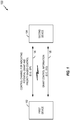
- FIG. 2 illustrates an example communication network 200 in which aspects of the present disclosure may be performed.
- techniques presented herein may be used to share a common set of resources between various devices having different priority levels.
- a base station (BS) 201 may include multiple antenna groups, one group including antennas 204 and 206, another group including antennas 208 and 210, and an additional group including antennas 212 and 214. In FIG. 2 , two antennas are shown for each antenna group, however, more or fewer antennas may be utilized for each antenna group.
- a wireless node 216 may be in communication with the antennas 212 and 214, where the antennas 212 and 214 transmit information to the wireless node 216 over a forward link 220 and receive information from the wireless node 216 over a reverse link 218.
- a wireless node 222 may be in communication with the antennas 204 and 206, where the antennas 204 and 206 transmit information to the wireless node 222 over a forward link 226 and receive information from the wireless node 222 over a reverse link 224.
- the BS 201 may also be in communication with other wireless nodes, which may be, for example, Intemet-of-Everything (IoE) devices.
- An IoE device 236 may be in communication with one or more other antennas of the BS 201, where the antennas transmit information to the IoE device 236 over a forward link 240 and receive information from the IoE device 236 over a reverse link 238.
- An IoE device 242 may be in communication with one or more other antennas of the BS 201, where the antennas transmit information to the IoE device 242 over a forward link 246 and receive information from the IoE device 242 over a reverse link 244.
- the communication links 218, 220, 224, 226, 238, 240, 244, and 246 may use different frequencies for communication.
- the forward link 220 may use a different frequency than that used by the reverse link 218, and forward link 240 may use a different frequency than that used by reverse link 238.
- the various concepts presented throughout this disclosure may be implemented across a broad variety of telecommunication systems, network architectures, and communication standards.
- 3GPP Third Generation Partnership Project
- EPS evolved packet system
- LTE long-term evolution
- LTE networks can provide end-to-end latency between a transmitting device and a receiving device on the order of 50 ms, with over-the-air latency for a particular packet being in the range of 10 ms.
- LTE functionality provides for a round trip time (RTT) for certain feedback signaling (i.e., hybrid automatic repeat request (HARQ) signaling) of at least about 8 ms, using a transmission time interval (TTI) of 1 ms.
- a TTI corresponds to a minimum duration of a unit of information that can be decoded.
- TDD time division duplex
- LTE provides for a one-size-fits-all approach, with all services and packets relying on these same latency ranges.
- Evolved versions of the LTE network may provide for many different types of services or applications, including but not limited to web browsing, video streaming, VoIP, mission critical applications, multi-hop networks, remote operations with real-time feedback (e.g., tele-surgery), etc.
- 5G fifth-generation
- These different sets of services may benefit from having multiple latency targets that are drastically different from one another.
- the one-size-fits-all aspects of the LTE network described above can make the multiplexing of traffic with different latency targets very difficult.
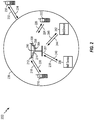
- FIG. 3 is a block diagram illustrating an exemplary scheduling entity 302 in wireless communication with a plurality of subordinate entities 304.
- the scheduling entity 302 transmits downlink data channel(s) 306 and downlink control channel(s) 308, while the subordinate entities transmit uplink data channel(s) 310 and uplink control channel(s) 312.
- the channels illustrated in FIG. 3 are not necessarily all of the channels that may be utilized between a scheduling entity 302 and subordinate entities 304, and those of ordinary skill in the art will recognize that other channels may be utilized in addition to those illustrated, such as other data, control, and feedback channels.
- the scheduling entity 302 may broadcast downlink data 306 to one or more subordinate entities 304.
- the term downlink may refer to a point-to-multipoint transmission originating at the scheduling entity 302.
- the scheduling entity 302 is a node or device responsible for scheduling traffic in a wireless communication network, including the downlink transmissions and, in some examples, uplink data 310 from one or more subordinate entities 304 to the scheduling entity 302.
- Another way to describe the scheme may be to use the term broadcast channel multiplexing.
- a scheduling entity may be, or may reside within, a base station, a network node, a user equipment (UE), an access terminal, or any suitable node in a wireless communication network.
- UE user equipment
- the term uplink may refer to a point-to-point transmission originating at a subordinate entity 304.
- the subordinate entity 304 is a node or device that receives scheduling control information, including but not limited to scheduling grants, synchronization or timing information, or other control information from another entity in the wireless communication network such as the scheduling entity 302.
- a subordinate entity may be, or may reside within, a base station, a network node, a UE, an access terminal, or any suitable node in a wireless communication network.
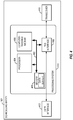
- FIG. 4 is a conceptual diagram illustrating an example of a hardware implementation for a scheduling entity 302 employing a processing system 414 that includes one or more processors 404.
- a processing system 414 that includes one or more processors 404.
- an element, or any portion of an element, or any combination of elements may be implemented with the processing system 414.
- the scheduling entity 302 may be any suitable radio transceiver apparatus, and in some examples, may be embodied by a base station (BS), a base transceiver station (BTS), a radio base station, a radio transceiver, a transceiver function, a basic service set (BSS), an extended service set (ESS), an access point (AP), a Node B, an eNode B (eNB), mesh node, relay, or some other suitable terminology.
- a base station may be referred to as a scheduling entity, indicating that the base station provides scheduling information to one or more subordinate entities.
- the scheduling entity 302 may be embodied by a wireless user equipment (UE).
- UE wireless user equipment
- a UE include a cellular phone, a smart phone, a session initiation protocol (SIP) phone, a laptop, a notebook, a netbook, a smartbook, a personal digital assistant (PDA), a satellite radio, a global positioning system (GPS) device, a multimedia device, a video device, a digital audio player (e.g., MP3 player), a camera, a game console, an entertainment device, a vehicle component, a wearable computing device (e.g., a smart watch, a health or fitness tracker, etc.), an appliance, a sensor, a vending machine, or any other similar functioning device.
- GPS global positioning system
- the UE may also be referred to by those skilled in the art as a mobile station (MS), a subscriber station, a mobile unit, a subscriber unit, a wireless unit, a remote unit, a mobile device, a wireless device, a wireless communication device, a remote device, a mobile subscriber station, an access terminal (AT), a mobile terminal, a wireless terminal, a remote terminal, a handset, a terminal, a user agent, a mobile client, a client, or some other suitable terminology.
- a UE may be referred to either as a scheduling entity, or a subordinate entity. That is, in various aspects of the present disclosure, a wireless UE may operate as a scheduling entity providing scheduling information to one or more subordinate entities, or may operate as a subordinate entity, operating in accordance with scheduling information provided by a scheduling entity.
- the processing system 414 may be implemented with a bus architecture, represented generally by the bus 402.
- the bus 402 may include any number of interconnecting buses and bridges depending on the specific application of the processing system 414 and the overall design constraints.
- the bus 402 links together various circuits including one or more processors (represented generally by the processor 404), a memory 405, and computer-readable media (represented generally by the computer-readable medium 406).
- the bus 402 may also link various other circuits such as timing sources, peripherals, voltage regulators, and power management circuits, which are well known in the art, and therefore, will not be described any further.
- a bus interface 408 provides an interface between the bus 402 and a transceiver 410.
- the transceiver 410 provides a means for communicating with various other apparatus over a transmission medium.
- a user interface 412 e.g., keypad, display, speaker, microphone, joystick
- the processor 404 is responsible for managing the bus 402 and general processing, including the execution of software stored on the computer-readable medium 406.
- the software when executed by the processor 404, causes the processing system 414 to perform the various functions described below for any particular apparatus.
- the computer-readable medium 406 may also be used for storing data that is manipulated by the processor 404 when executing software.
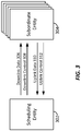
- FIG. 5 is a conceptual diagram illustrating an example of a hardware implementation for an exemplary subordinate entity 304 employing a processing system 514 that includes one or more processors 504.
- a processing system 514 that includes one or more processors 504.
- an element, or any portion of an element, or any combination of elements may be implemented with the processing system 514.
- the processing system 514 may be substantially the same as the processing system 414 illustrated in FIG. 4 , including a bus interface 508, a bus 502, memory 505, a processor 504, and a computer-readable medium 506.
- the subordinate entity 304 may include a user interface 512 and a transceiver 510 substantially similar to those described above in FIG. 4 .
- the processor 504, as utilized in a subordinate entity 304, may be used to implement any one or more of the processes described below.
- transmissions to and from devices with different priority levels may be multiplexed over time and/or over a region of sub-carrier resources.
- a lower-priority user may be subject to scheduling updates by a higher-priority user that might impact its resources (in the form of TTI puncturing).
- aspects of the present disclosure may help address this scenario by providing certain information to mobile devices with different priorities that allow them to detect potential resource allocation collisions and act accordingly.
- information may be provided via a new indication channel and a procedure to signal scheduling priority information.
- control signaling occurs typically at subframe or certain fixed periodicity, which is the smallest regular DL scheduling time unit and there is no conflicting bursty activities scheduled at a even finer periodicity.
- services at various levels of priorities (or QoS) and/or RTT latencies may be multiplexed over time and over a region of spectral (namely, sub-carrier) resources in an OFDMA system, with different transmission time intervals (TTIs).
- TTI generally refers to the duration of a transmission on a radio link and is generally equal to a periodicity at which a transport block set is transferred by a physical layer (e.g., a TTI is generally related to the size of the data blocks passed from the higher network layers to the radio link layer).
- variable transmission time intervals may be utilized to accommodate different levels of priority for different devices, or different applications, or different categories of data to be communicated over the air interface.
- TTIs may be utilized, with each shorter TTI packet having higher priority than any longer TTI packet.
- the example of FIG. 6 shows TTIs 602 with a period of 125 ⁇ s (highest priority), TTIs 604 with a period of 250 ⁇ s, TTIs 606 with a period of 500 ⁇ s, and TTIs 608 with a period of 1 ms (lowest priority).
- this short TTI transmission may puncture the ongoing scheduled data transmission.
- a relatively lower-priority user may be subject to bursty yet conflicting scheduling updates (in the form of transmission time interval (TTI) puncturing) by a relatively higher-priority user.
- TTI transmission time interval
- a low latency or mission critical user may take priority over a nominal user.
- legacy signaling for DCI may become unnecessarily excessive, as the channel conditions become less varying.
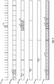
- FIG. 7 shows TTIs 702 with a period of 31.25 ⁇ s (highest priority), TTIs 704 with a period of 62.5 ⁇ s, TTIs 706 with a period of 125 ⁇ s, TTIs 708 with a period of 250 ⁇ s, TTIs 710 with a period of 500 ⁇ s, and TTIs 712 with a period of 1 ms (lowest priority).
- a TTI 714 assigned with a grant to a higher priority device may result in puncturing to a larger TTI 716 assigned to a device with a lower priority (TTIs 712, bottom row).
- a TTI 718 assigned with a grant to a higher priority device may result in puncturing to a larger TTI 720 assigned to a device with a lower priority (TTIs 706, third row).
- the TTIs 718 and 720 may, in turn, result in puncturing to the larger TTI 716 assigned to the even lower priority device (TTIs 712, bottom row).
- aspects of the present disclosure may provide an efficient and reliable signaling design to address such challenges by supporting users at both higher and lower priorities in the event of bursty scheduling updates for users' in-time actions.
- a control channel may be provided.
- the control channel may be embedded within an allocated data portion of a frame or subframe.
- a scheduling entity may communicate with one or more subordinate entities utilizing an OFDMA air interface. On this air interface, time-frequency resources may be divided into frames or subframes.
- a subframe may include a control/grant portion and a data portion.
- the scheduling entity may utilize the control/grant portion to provide scheduling information, indicating scheduled time-frequency resources within the data portion.
- an embedded control channel may be provided within the data portion, and outside of the control/grant portion of the subframe.
- PICH Priority Indication Channel
- SPIs scheduling priority indices
- the PICH may take different forms in different implementations.
- the PICH is a common PICH (CPICH).
- the PICH is a directed common PICH (DC-PICH).
- the PICH is a dedicated PICH (DPICH).
- an SPI refers to a priority level assigned to a device, and each SPI generally refer to a scheduling priority of users with that SPI.
- each SPI value may correspond to a unique TTI length (e.g., with higher priority SPIs having shorter TTIs and lower priority TTIs having longer TTIs).
- Each user may be assigned by the network at least one SPI "SPIuser", each of which corresponds to "TTI user", an associated TTI for the user. For example, if a user has a single bearer, a single SPI may be assigned. Alternatively, if a user has multiple bearers, the bearers could share one SPI or different SPIs could be assigned to one or more of the bearers (e.g., different sets of bearers may share different SPIs).
- the network may update the SPI_user as the user's target RTT changes.
- TTI_min a quantity referred to as "TTI_min” or “TTI_smallest” may be signaled by the network to indicate the smallest TTI_user value among all active users (e.g., generally corresponding to the highest priority SPI among such users).
- the disclosure relates in some aspects to a tiered DL signaling procedure design to support multi-priority scheduling (MPS).
- MPS multi-priority scheduling
- a two tier example is set described below. It should be appreciated, however, that more than two tiers may be used in other implementations.
- the network sends scheduling indicators via PICH, a channel to indicate resource block level (RB-level) scheduling priorities for DL data schedules.
- This channel may be common to all users or individually dedicated to users. A different (e.g., coarser) granularity could be used in other implementations.
- the scheduling indicators may indicate sub-band level scheduling priorities.
- the SPIs do not differentiate among individual users. For example, SPIs typically do not include user identifiers.
- the scheduling indicator information is transmitted on an OFDM symbol once every T_pich time interval.
- the T_pich value is commonly signaled by the network.
- the network assigns to each user a scheduling indicator (e.g., an "SPI user") which uniquely corresponds to a TTI length "TTI user".
- SPI user for a given user quantifies the priority for the user.
- the network also schedules RBs to the users (e.g., schedules RBs with SPIs).
- the network sends the scheduling indications to users once every TTI_min, using one of the following schemes.
- a first scheme uses a common (or multi-cast) scheduling priority indicator channel.
- a common channel carries scheduling priority indicators for all active users.
- a second scheme uses a uni-cast scheduling indicator channel.
- This is a dedicated channel that carries scheduling indicators for a user.
- the channel may, for example, indicate one of the following: “start/resume”, “pause”, “stop”, to start, pause, or stop reception of the physical downlink shared channel (PDSCH) for the corresponding TTI min.
- PDSCH physical downlink shared channel
- Each active user monitors the scheduling indication channel (in either the first scheme or the second scheme) for a possible grant indication or a possible scheduling conflict.
- the user may monitor on the common channel once every TTI_user by finding SPI_user for possible DL grants available to the user. This is a "possible" grant because a given SPI could map to multiple users (e.g., that have the same priority level).
- a user may detect a possible higher priority scheduling conflict (puncturing) for a TTI_min. For example, the user may pause reception and/or decoding if a conflict is detected (e.g., a higher priority SPI is received). Otherwise, the user may start/resume the reception and/or the decoding. As another example, if the user detects a "stop" indicator, the user may stop reception and/or decoding until the end of TTI_user.
- Each active user when assigned with a DL grant in the current TTI_user, also monitors the SPIs on the command channel once every T_pich by finding any higher-priority SPI (higher than SPI user) for possible higher-priority scheduling update (e.g., TTI puncturing). Thus, an active user may check the SPIs more often to see if a higher priority SPI (higher priority than the user) is indicated. If there is a higher-priority SPI that conflicts with the user's on-going DL grant, the user pauses decoding for the on-going grant.
- a possible new DL grant exists.
- the user further looks for confirmation by decoding and detecting dedicated downlink control information (DCI) for a possible DL grant.
- DCI dedicated downlink control information
- the user may determine whether a potential grant indicated in Tier 1 is a dedicated grant for that particular user by monitoring dedicated channel information.
- a user may derive grant details through physical downlink control channel (PDCCH) detection and decoding for every TTI user.
- PDCCH physical downlink control channel
- the user may decode DCI on a dedicated channel.
- the network prepares an SPI user bitmap to further indicate for the user the RB allocation for the DL grant.
- the user may derive the length of the SPI user bitmap and construct the SPI sequence.
- the SPI sequence may be constructed based on a known SPI user from the Common Priority Indication Channel.
- the user may derive the RB allocation for the grant.
- the user may extract the SPI user bitmap from the DCI and mask the bitmap with the constructed SPI sequence to derive the final RB allocation for the grant. It is possible for a user to be scheduled for a DL grant for a TTI user, while being punctured for the beginning of the TTI_min interval.
- a given grant (e.g., associated with a particular SPI) may be associated with one or more specific RBs.
- the signaling may indicate only the specifically granted RBs (e.g., rather than using a bit map corresponding to all of the RBs).
- one or more sub-bands may be allocated for a given user (e.g., an SPI may be specified per sub-band level, not per RB).
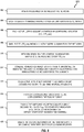
- FIG. 8 illustrates a process 800 for supporting the signaling of control information in accordance with some aspects of the disclosure.
- the process 800 may take place, at least on part, within at least one processing circuit (e.g., the processing circuit 1510 of FIG. 15 ), which may be located in an access terminal, a base station, some other suitable apparatus, or a combination of these apparatuses.
- the process 800 may be implemented by any suitable apparatus or apparatuses capable of supporting control-related operations.
- a high priority monitor space is predefined (e.g., by a network operator) or signaled by a network.
- the HPMS may be a subset of the entire resource block (RB) allocation space of an OFDM symbol.
- RBs in the HPMS may be punctured, at the network's decision, with a higher priority scheduling update.
- a set of valid TTI lengths is defined for the network to assign from (e.g., based on user priority) in a multiplexed multi-priority scheduling system (MMPSS).
- MMPS multiplexed multi-priority scheduling system
- a TTI consists of one or more equal-duration OFDM symbols with one CP duration between any two neighboring symbols.
- each TTI length is uniquely mapped to a scheduling indicator (e.g., an SPI).
- an SPI may be defined as identifying an "unassigned" SPI.
- the smallest scheduling unit for a user may be one resource block (RB).
- RB resource block
- each active user is assigned a particular scheduling indicator (e.g., SPI_user), which uniquely corresponds to a TTI length (TTI_user).
- SPI_user a scheduling indicator assigned to a user.
- TTI_user a scheduling indicator assigned to a user.
- the network may also update the scheduling indicator for a user as it deems necessary.
- TTI_min the smallest TTI (TTI_min) among all active users is signaled by the network.
- the network sends the RB-level scheduling indicators on PICH at an OFDM symbol once every TTI_min (T PICH ).
- the scheduling indicator indicates that an RB is unassigned or indicates the assigned scheduling indicator value (e.g., an SPI value) for each RB being actively scheduled (namely, assigned) for downlink (DL) transmission.
- the assigned scheduling indicator value e.g., an SPI value
- each active user if not currently assigned a grant, decodes PICH every TTI_user time interval (TTI length).
- TTI length TTI_user time interval
- the user monitors the entire RB allocation space for possible new DL grants assigned to the user. For example, if an SPI that matches the SPI assigned to the user is received, a new DL grant for the user is possible.
- a given user may confirm whether the grant is for that user (e.g., by performing the Tier 2 operations discussed above).
- each active user who has been assigned a grant decodes PICH every TTI_min (T PICH ) for a start/stop indication.
- the user monitors only in the HPMS for possible scheduling updates until the assigned DL grant expires.
- the start/stop indication may be an explicit command to the user.
- the command may instruct the user to start, resume, pause, or stop reception of data for a corresponding TTI_min.
- the start/stop indication may be an SPI. If an SPI at a higher priority (than the SPI user) is detected in the HPMS that conflicts with the user's on-going grant, a scheduling update with higher priority puncturing may be assumed. This will result in the user pausing on-going decoding for the grant assigned to the user. Conversely, if the user has previously paused on-going decoding for an assigned grant due to a higher priority scheduling update, and the conflict no longer exists as indicated by the SPIs in the HPMS, this will result in the user resuming reception decoding for the paused assigned grant as long as the grant has not expired.
- the user starts/stop decoding for the pending grant if an SPI conflict is identified (e.g., for a common channel) or an explicit command is received (e.g., for a dedicated channel) as discussed above.
- the DCI is classified into 2 subsets, based on the relative rates of change of the information: semi-static information and dynamic information.
- Semi-static information includes at least one parameter that varies, for example, once every multiple TTIs. Examples of such information include: ⁇ modulation and coding scheme (MCS), RB allocation ⁇ .
- MCS modulation and coding scheme
- the semi-static information may be excluded in a DCI, as it may not change as frequently as in every TTI.
- Dynamic information includes at least one parameter that varies, for example, once every TTI. Examples of such information include: ⁇ precoding matrix index (PMI), new data indicator (NDI), redundancy version (RV), HARQ ID ⁇ .
- PMI precoding matrix index
- NDI new data indicator
- RV redundancy version
- HARQ ID HARQ ID
- a DCI that includes both semi-static information and dynamic information is defined as a normal DCI (N-DCI).
- a DCI without semi-static information is defined as a light DCI (L-DCI).
- option 1 blind decode
- option 2 coherent decode
- the network transmits N-DCI at a subset of the TTIs (by a pre-defined policy, which is a design choice) that may be inferred by the UE, such that both the network and the UE always transmit/decode a DCI coherently.
- the network may assume unsuccessful reception of the N-DCI for the UE unless the network receives an HARQ ACK for the DCI-corresponding DL data (or PDSCH).
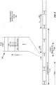
- FIG. 9 illustrates an example of the type of information that may be conveyed in a PICH regarding per-SPI resource allocation. TTIs of various priorities and SPIs may be indicated on the PICH. For example, for RB i, an SPI value of P0 is assigned, for RB i+1, an SPI value of PI is assigned, and so on. For an RB unassigned to any user, an "unassigned" value may be used as the SPI.
- the network may extract the corresponding SPI user values and send them on PICH once every TTI_smallest (e.g., in a first OFDM symbol 904 of the higher priority (smallest) TTI 906).
- FIG. 9 also illustrates an example of a T PICH period 908 and a lower priority (longer) TTI 910.
- SPI allocation types there may be various types of SPI allocation types in a PICH. For example, there may be an "RB allocation type” (as illustrated in FIG. 9 ) or a "sub-band allocation” type as discussed below.
- RB allocation type as illustrated in FIG. 9
- sub-band allocation as discussed below.
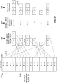
- FIG. 10 illustrates an example derivation of SPI sequences 1002, variable length SPI user bitmaps 1004, and RB assignment 1006.
- a user at SPI_user priority may determine an "SPI sequence" and the sequence length from the Common Priority Indication Channel (CPIC) 1008 by counting the number of SPIs matching to SPI_user.
- CPIC Common Priority Indication Channel
- the SPI 1010 for a first RB or sub-band is mapped 1012 to a first element 1014 of an SPI sequence.
- the resultant RB assignment 1006 can be determined.
- the bitmaps may result in a reduction in the size of the RB assignment.
- the constructed SPI sequence along with its length is used for detecting and decoding the user's DCI on a dedicated channel, to finally derive the user's RB allocation for the DL grant.
- a separate variable-length DCI design may support detection and decoding for such a DCI design.
- the SPI allocation (represented by a line 1018) on the CPIC may be per-RB or per sub-band.
- an RB allocation space may be partitioned into sub-bands and one SPI may be indicated for each sub-band (e.g., with a similar principle with an SPI user bitmap for RB allocation as shown in FIG. 9 ).
- FIG. 11 illustrates an example of a processing procedure for a device (e.g., a UE) to monitor for PICH.
- a higher-priority monitor space HPMS
- HPMS higher-priority monitor space
- a higher-priority scheduling update may be made by the network in (e.g., only in) HPMS.
- TTI_min is defined (commonly signaled by the network), and SPI user or TTI_user are assigned to a user by the network (block 1102).
- each active user who has been assigned with a DL grant in current TTI_user shall additionally decode PICH once in every TTI_min to monitor possible scheduling updates (to detect for a possible collision). If a higher-priority SPI (higher than SPI user) is detected that conflicts (in terms of RB allocation) with the user's on-going grant, a higher-priority scheduling update (puncturing) exists. The user may take action accordingly. For example, the user may pause on-going data decoding (at least of resources that have been punctured due to an allocation to a higher priority.
- the user may resume reception/decoding for the paused assigned grant as long as the grant has not expired.
- operational flow proceeds to block 1106.
- the user decodes the indication channel once every TTI_min to check if reception needs to be paused/stopped. If not (block 1110), the user starts/resumes reception and decoding. If so (block 1108), the user pauses/stops on-going decoding according to the scheduling indicator.
- each active user when not being assigned with a DL grant, may decode CPICH once every TTI_user to monitor for possible new grant. For example, if a matching SPI_user is detected, a new DL grant for the user is possible. If it is determined at block 1104 that a DL grant is not assigned, operational flow proceeds to block 1112. Here, the user decodes the indication channel every TTI_user to detect if SPI_user exists. If not (block 1114), no action is taken since no DL grant was detected. If so, operational flow proceeds to block 1116. In this case, a DL grant possibly exists for the user. Thus, the user attempts to detect DCI on a dedicated channel.
- the user uses SPI_user to derive the length of the SPI user bitmap, and uses the SPI user bitmap in DCI to derive the RB allocation for the grant as discussed above at FIG. 10 (block 1120).
- a flexible DCI option may be employed as discussed above.
- the user may derive semi-static information and extract dynamic information (block 1122). At this point, the entire DL grant is derived and the user is ready to decode the DL data (e.g., from PDSCH).
- FIG. 12 illustrates another example of a processing procedure for a device (e.g., a UE) to support multi-priority scheduling.
- a device e.g., a UE
- This example illustrates the self-scheduling signaling mode (SSSM) and an SPI-specific approach.
- SSSM self-scheduling signaling mode
- DCI and data are merged for encoding and transmission.
- DCI is signaled via PDCCH (SSSM inactive).
- SSSM active DCI is signaled via PDSCH (SSSM active).
- T PICH is defined (commonly signaled by the network)
- HPMS is signaled on PICH (commonly signaled by the network)
- SPI_user is assigned to each user by the network.
- the user decodes PICH once every T PICH to check if any higher priority SPI conflicts with the user's on-going DL grant. If there is a conflict (a higher priority scheduling update (TTI puncture) occurs), the user pauses on-going decoding in the current TTI_user (block 1208). Conversely (no conflict at block 1206), if the user has previously paused an on-going DL grant, the user checks to see if the previous SPI conflict has lifted (block 1210). If the conflict has not lifted (block 1212), the user continues with on-going data decoding (i.e., there is no change in the user operations). If the conflict has lifted, the user resumes the paused decoding of the DL grant (block 1214).
- operational flow proceeds to block 1216.
- the user decodes the PICH every TTI_user to see if SPI_user exists in HPMS. If not (block 1218), no action is taken. If so, operational flow proceeds to block 1220. The user then determines whether SSSM is active. If not (block 1222), the user determines whether a grant is detected in DCI (e.g., via PDCCH). If a grant was not detected (block 1226), no action is taken since no DL grant was detected. Otherwise, a new DL grant is found (block 1224), and the user decodes the DL data (e.g., on PDSCH).
- DCI e.g., via PDCCH
- SSSM SSSM is active at block 1220
- operational flow proceeds to block 1228.
- the user decodes the received data (e.g., PDSCH) on the assumption of unchanged semi-static information in DCI.
- the data decoding is either successful (block 1230) or not (block 1232). If the data decoding was not successful (e.g., PDSCH decode fails), the user may send a NACK on the uplink (UL).
- Tier 1 control signaling with common scheduling priority indicators a user decodes the common scheduling priority indicators for two purposes.
- the first purpose is to check if a possible new DL grant is available for the user (e.g., check once every TTI user).
- the second purpose is to confirm if a conflicting higher-priority schedule update occurs while the user has an on-going DL grant (e.g., confirm once every T PICH when a DL grant is assigned for current TTI_user).
- Tier 2 control signaling with dedicated DL grants, once tier 1 signaling confirms a possible new DL grant is available, the user further decodes DCI to confirm such new DL grant. Furthermore, if SSSM (self-scheduling signaling mode) is active, the DCI is signaled along with DL data (i.e., "merged" for decoding and transmission, which further reduces processing overhead at the receiver). Otherwise, if SSSM is not active, legacy signaling (i.e., separation between DCI and DL data) is used
- N-DCI and L-DCI Two types of DCI, N-DCI and L-DCI, are defined, which enables flexibility in including both semi-static information and dynamic information or including only dynamic information.
- the exact choice of parameters to be included in N-DCI and L-DCI is by design choice. Two options (e.g., at the choice of the designer) for signaling/decoding have been described. In either option, unnecessarily excessive signaling in a subset of the DCI may be eliminated, which enables further saving in the multi-priority scheduling system.
- conventional wireless communication e.g., LTE
- conventional wireless communication employ regular PDCCH schedules and configure data decoding in every single DCI, which may be too heavy (e.g., too processing intensive) for shorter TTI lengths.
- SPS semi-persistent scheduling
- regular PDCCH and SPS are not specifically designed for multi-priority scheduling with dynamic updates.
- RB allocation typically represent 30 ⁇ 60% of the entire DCI.
- LTE PDCCH format 1/1C for 20 MHz RB allocation occupies 60% of DCI.
- a relatively finer spatial resolution in signal transmission may be achieved.
- a relatively finer spatial resolution in signal transmission namely, beam-forming
- a relatively finer spatial resolution in signal transmission may be achieved.
- such superior transmission capability is used for dedicated (or UE-specific) signaling such as a UE-specific reference signal (UERS) and a dedicated control signal (e.g., LTE PDCCH)
- UERS UE-specific reference signal
- LTE PDCCH dedicated control signal
- the disclosure relates in some aspects to the use of a directional common channel (DCC, where the term "common” refers in some aspects to a common payload intended for multiple users), to utilize the available capability of a larger amount of transmit antennas through beam-forming transmission to individual users to beam-form a common payload to multiple users.
- DCC directional common channel
- a reference signal of a suitably designed sub-carrier pattern may be transmitted along with the same multiple-antenna system.
- users may receive both the DCC payload signal and the reference signal through identical antennas and the MIMO propagation channel, and use such a reference signal as a source for estimation (e.g., channel estimation and interference estimation) to assist detecting and decoding the DCC payload signal.
- common physical channels may be suitable for this proposed type of DCC technique.
- Such common channels include a common broadcast channel, a pilot channel, and a common indicator channel.
- the PICH may be sent directionally (e.g., with beam-forming). This may involve reusing a same set of sub-carrier resources, and uni-cast transmission of the channelized common payload through directional signaling by properly using spatial characteristics of individual users.
- a UE-specific reference signal may be transmitted along with the common payload signal, by properly using spatial characteristics of individual users (same characteristics used as those used for the common payload signal).
- Legacy (broadcast/non-direction/non-beam-forming) common channels typically can use only a lower modulation order (e.g., QPSK in LTE PDCCH) for transmission due to link-budget limitations (such as for cell edge users).
- DCC breaks those limitations and enables spatial processing at the transmitter for beam-forming toward individual users and thus a higher modulation order may be used.
- Sub-carrier resource efficiency Since the same payload is targeted for multiple users (receivers) as a common channel, post-modulation frequency-domain constellation symbols targeted for multiple receiving users may be weighted and linearly superposed over same (re-used) set of sub-carriers (due to a common payload) at the antenna system during transmission (Tx) processing.
- DC-PICH Directional Common Priority Indication Channel
- Sub-carrier resource efficiency - O(N) vs. O(logN) To deliver DL grant (scheduling) information to multiple users, instead of relying completely in UE dedicated signaling (e.g., LTE PDCCH), DC-PICH uses common scheduling priority indicators to provide "top-level" indications to all active users for needed actions. Specifically, in LTE PDCCH, one copy of RBG bitmap information is transmitted to each active user with the grant assignment, while in DC-PICH, only the common SPIs are transmitted, resulting in significant savings in sub-carrier resources. A complexity-order comparison follows.
- LTE PDCCH (alloc type 0): Assume an RBG table size is "T" bits. For “N” active users, a total of “T ⁇ N” bits are needed against sub-carrier resources to transmit.
- Link performance efficiency Conventionally, DL grant schedule information is transmitted through non-directional transmission (e.g., LTE PDCCH), which is not as spectrally and power efficient, and is not as link performance efficient, when compared with beam-forming DC-PICH (e.g., in combination with another dedicated channel as described herein).
- LTE PDCCH non-directional transmission
- DC-PICH beam-forming DC-PICH
- FIGs. 13 and 14 illustrate example operations corresponding to transmitting and monitoring for a CPICH.
- FIG. 13 illustrates a process 1300 for monitoring for collisions by a mobile device (e.g., a UE), based on SPI information and resource allocation, in accordance with some aspects of the disclosure.
- the process 1300 may take place within a processing circuit (e.g., the processing circuit 1510 of FIG. 15 ), which may be located in an access terminal, a base station, or some other suitable apparatus.
- a processing circuit e.g., the processing circuit 1510 of FIG. 15
- the process 1300 may be implemented by any suitable apparatus capable of supporting control-related operations.
- the process 1300 begins, at block 1302, by determining a scheduling priority index (SPI) for the mobile device, a transmission time interval (TTI) for the mobile device corresponding to the SPI, and a shortest TTI for active mobile devices in the network that share a common resource space with the mobile device.
- SPI scheduling priority index
- TTI transmission time interval
- this determination may involve or may be the result of receiving signaling indicating the SPI for the mobile device and the shortest TTI.
- the mobile device monitors for a possible downlink grant at least once every TTI for the mobile device.
- the monitoring for a possible downlink grant at least once every TTI for the mobile device may involve monitoring for a common priority indication channel (CPICH) that indicates resources assigned per SPI.
- CPICH may indicate resources with a granularity of an integer value of one or more resource blocks (RBs).
- RBs resource blocks
- the CPICH may indicate resources with a granularity of an integer value of sub-bands.
- the CPICH may be transmitted in a first symbol of every shortest TTI.
- the mobile device detects a downlink grant for the mobile device during the monitoring.
- the detecting a downlink grant for the mobile device may involve detecting a CPICH with a resource assignment for an SPI matching an SPI of the mobile device.
- the mobile device monitors at least once every shortest TTI for DL grants to other mobile devices, in response to the detection at block 1306.
- the monitoring at least once every shortest TTI for DL grants to other mobile devices may involve monitoring for a common priority indication channel (CPICH) that indicates resources assigned per SPI.
- CPICH common priority indication channel
- the mobile device takes action in response to detecting a collision between resources for the DL grant to the mobile device and a DL grant to another mobile having a higher priority SPI with a lower corresponding TTI than the mobile device.
- taking action involves pausing on-going data decoding for the DL grant when reaching colliding resources. In this case, data decoding may be resumed for remaining non-colliding resources.
- FIG. 14 illustrates a process 1400 for signaling SPI information and resource allocation by a network node (e.g., a base station) in accordance with some aspects of the disclosure.
- the process 1400 may take place within a processing circuit (e.g., the processing circuit 1510 of FIG. 15 ), which may be located in an access terminal, a base station, or some other suitable apparatus.
- the process 1400 may be implemented by any suitable apparatus capable of supporting control-related operations.
- the process 1400 begins, at block 1402, by signaling, to a mobile device in the network, a scheduling priority index (SPI) for the mobile device and a shortest transmission time interval (TTI) for active mobile devices in the network that share a common resource space with the mobile device.
- SPI scheduling priority index
- TTI shortest transmission time interval
- the network node transmits, each shortest TTI, a common priority indication channel (CPICH) that indicates resources assigned per SPI for downlink (DL) grants.
- the CPICH may indicate resources with a granularity of an integer value of one or more resource blocks (RBs).
- the CPICH may indicate resources with a granularity of an integer value of sub-bands.
- the CPICH may be transmitted in a first symbol of every shortest TTI.
- the CPICH may be sent via at least one of: a beam-formed transmission or a directional transmission.
- the CPICH may be sent using spatial characteristics of individual users.
- the CPICH may be sent with reference signals specific to the individual users.
- FIG. 15 is an illustration of an apparatus 1500 that may support scheduling according to one or more aspects of the disclosure.
- the apparatus 1500 could embody or be implemented within a mobile device, an access point, or some other type of device that supports wireless communication.
- the apparatus 1500 could embody or be implemented within an access terminal (e.g., a UE), a base station (BS), or some other type of device.
- the apparatus 1500 could embody or be implemented within a mobile phone, a smart phone, a tablet, a portable computer, a server, a personal computer, a sensor, an entertainment device, a medical device, or any other electronic device having circuitry.
- the apparatus 1500 includes a communication interface (e.g., at least one transceiver) 1502, a storage medium 1504, a user interface 1506, a memory device 1508, and a processing circuit 1510.
- the signaling bus may include any number of interconnecting buses and bridges depending on the specific application of the processing circuit 1510 and the overall design constraints.
- the signaling bus links together various circuits such that each of the communication interface 1502, the storage medium 1504, the user interface 1506, and the memory device 1508 are coupled to and/or in electrical communication with the processing circuit 1510.
- the signaling bus may also link various other circuits (not shown) such as timing sources, peripherals, voltage regulators, and power management circuits, which are well known in the art, and therefore, will not be described any further.
- the communication interface 1502 may be adapted to facilitate wireless communication of the apparatus 1500.
- the communication interface 1502 may include circuitry and/or programming adapted to facilitate the communication of information bi-directionally with respect to one or more communication devices in a network.
- the communication interface 1502 may be configured for wire-based communication.
- the communication interface 1502 may be coupled to one or more antennas 1512 for wireless communication within a wireless communication system.
- the communication interface 1502 can be configured with one or more standalone receivers and/or transmitters, as well as one or more transceivers.
- the communication interface 1502 includes a transmitter 1514 and a receiver 1516.
- the memory device 1508 may represent one or more memory devices. As indicated, the memory device 1508 may maintain schedule-related information 1518 along with other information used by the apparatus 1500. In some implementations, the memory device 1508 and the storage medium 1504 are implemented as a common memory component. The memory device 1508 may also be used for storing data that is manipulated by the processing circuit 1510 or some other component of the apparatus 1500.
- the storage medium 1504 may represent one or more computer-readable, machine-readable, and/or processor-readable devices for storing programming, such as processor executable code or instructions (e.g., software, firmware), electronic data, databases, or other digital information.
- the storage medium 1504 may also be used for storing data that is manipulated by the processing circuit 1510 when executing programming.
- the storage medium 1504 may be any available media that can be accessed by a general purpose or special purpose processor, including portable or fixed storage devices, optical storage devices, and various other mediums capable of storing, containing or carrying programming.
- the storage medium 1504 may include a magnetic storage device (e.g., hard disk, floppy disk, magnetic strip), an optical disk (e.g., a compact disc (CD) or a digital versatile disc (DVD)), a smart card, a flash memory device (e.g., a card, a stick, or a key drive), a random access memory (RAM), a read only memory (ROM), a programmable ROM (PROM), an erasable PROM (EPROM), an electrically erasable PROM (EEPROM), a register, a removable disk, and any other suitable medium for storing software and/or instructions that may be accessed and read by a computer.
- a magnetic storage device e.g., hard disk, floppy disk, magnetic strip
- an optical disk e.g., a compact disc (CD) or a digital versatile disc (DVD)
- a smart card e.g., a flash memory device (e.g., a card, a stick, or
- the storage medium 1504 may be embodied in an article of manufacture (e.g., a computer program product).
- a computer program product may include a computer-readable medium in packaging materials.
- the storage medium 1504 may be a non-transitory (e.g., tangible) storage medium.
- the storage medium 1504 may be coupled to the processing circuit 1510 such that the processing circuit 1510 can read information from, and write information to, the storage medium 1504. That is, the storage medium 1504 can be coupled to the processing circuit 1510 so that the storage medium 1504 is at least accessible by the processing circuit 1510, including examples where at least one storage medium is integral to the processing circuit 1510 and/or examples where at least one storage medium is separate from the processing circuit 1510 (e.g., resident in the apparatus 1500, external to the apparatus 1500, distributed across multiple entities, etc.).
- Programming stored by the storage medium 1504 when executed by the processing circuit 1510, causes the processing circuit 1510 to perform one or more of the various functions and/or process operations described herein.
- the storage medium 1504 may include operations configured for regulating operations at one or more hardware blocks of the processing circuit 1510, as well as to utilize the communication interface 1502 for wireless communication utilizing their respective communication protocols.
- the processing circuit 1510 is generally adapted for processing, including the execution of such programming stored on the storage medium 1504.
- code or “programming” shall be construed broadly to include without limitation instructions, instruction sets, data, code, code segments, program code, programs, programming, subprograms, software modules, applications, software applications, software packages, routines, subroutines, objects, executables, threads of execution, procedures, functions, etc., whether referred to as software, firmware, middleware, microcode, hardware description language, or otherwise.
- the processing circuit 1510 is arranged to obtain, process and/or send data, control data access and storage, issue commands, and control other desired operations.
- the processing circuit 1510 may include circuitry configured to implement desired programming provided by appropriate media in at least one example.
- the processing circuit 1510 may be implemented as one or more processors, one or more controllers, and/or other structure configured to execute executable programming.
- Examples of the processing circuit 1510 may include a general purpose processor, a digital signal processor (DSP), an application specific integrated circuit (ASIC), a field programmable gate array (FPGA) or other programmable logic component, discrete gate or transistor logic, discrete hardware components, or any combination thereof designed to perform the functions described herein.
- DSP digital signal processor
- ASIC application specific integrated circuit
- FPGA field programmable gate array
- a general purpose processor may include a microprocessor, as well as any conventional processor, controller, microcontroller, or state machine.
- the processing circuit 1510 may also be implemented as a combination of computing components, such as a combination of a DSP and a microprocessor, a number of microprocessors, one or more microprocessors in conjunction with a DSP core, an ASIC and a microprocessor, or any other number of varying configurations. These examples of the processing circuit 1510 are for illustration and other suitable configurations within the scope of the disclosure are also contemplated.
- the processing circuit 1510 may be adapted to perform any or all of the features, processes, functions, operations and/or routines for any or all of the apparatuses described herein.
- the processing circuit 1510 may be configured to perform any of the steps, functions, and/or processes described with respect to FIGs. 1 , 8 - 14 , and 16 .
- the term "adapted" in relation to the processing circuit 1510 may refer to the processing circuit 1510 being one or more of configured, employed, implemented, and/or programmed to perform a particular process, function, operation and/or routine according to various features described herein.
- the processing circuit 1510 may be a specialized processor, such as an application specific integrated circuit (ASIC) that serves as a means for (e.g., structure for) carrying out any one of the operations described in conjunction with FIGs. 1 , 8 - 14 , and 16 .
- ASIC application specific integrated circuit
- the processing circuit 1510 may serve as one example of a means for transmitting and/or a means for receiving.
- the processing circuit 1510 may include one or more of a circuit/module for determining an interval 1520, a circuit/module for communicating 1522, a circuit/module for decoding 1524, a circuit/module for determining a length 1526, or a circuit/module for determining a resource block allocation 1528.
- the circuit/module for determining an interval 1520 may include circuitry and/or programming (e.g., code for determining an interval 1530 stored on the storage medium 1504) adapted to perform several functions relating to, for example, determining an interval for communicating a scheduling indicator.
- the determination of the interval may involve one or more of: defining the interval, receiving the interval (e.g., receiving an indication of the interval from another apparatus or another component), obtaining the interval (e.g., retrieving an indication of the interval from a memory device or some other component), and so on.
- the circuit/module for determining an interval 1520 determines whether an interval matches a bearer associated with a device (e.g., a UE).
- the circuit/module for determining an interval 1520 may identify a bearer associated with the UE and then identify the interval (e.g., as shown in FIG. 7 ) mapped to that bearer. These determinations may be based, for example, on mappings retrieved from the memory device 1508 or obtained in some other manner. The circuit/module for determining an interval 1520 may then output an indication of the interval to a component of the apparatus 1500 (e.g., the memory device 1508 or some other component).
- a component of the apparatus 1500 e.g., the memory device 1508 or some other component.
- the circuit/module for communicating 1522 may include circuitry and/or programming (e.g., code for communicating 1534 stored on the storage medium 1504) adapted to perform several functions relating to, for example, sending and/or receiving information.
- the information is a scheduling indicator and the circuit/module for communicating 1522 communicates the scheduling indicator according to an interval (e.g., received from the circuit/module for determining an interval 1520, retrieved from the memory device 1508, or obtained in some other manner).
- the communication interface 1502 includes the circuit/module for communicating data 1522 and/or the code for communicating 1534.
- the communicating involves the circuit/module for communicating 1522 receiving information directly from a device that transmitted the data or receiving information from a component of the apparatus 1500 (e.g., the receiver 1516, the memory device 1508, or some other component).
- the circuit/module for communicating 1522 may process (e.g., decode) the received information.
- the circuit/module for communicating 1522 then outputs the received information to a component of the apparatus 1500 (e.g., the memory device 1508 or some other component).
- the communicating involves sending information to another component of the apparatus 1500 (e.g., the transmitter 1514) for transmission to another device or sending information directly to an ultimate destination (e.g., if the circuit/module for communicating 1522 includes a transmitter).
- the circuit/module for communicating 1522 initially obtains information to be communicated (e.g., from the memory device 1508 or some other component).
- the circuit/module for communicating 1522 may process (e.g., encode) the information to be transmitted.
- the circuit/module for communicating 1522 then causes the information to be transmitted.
- the circuit/module for communicating 1522 can directly transmit the information or pass the information to the transmitter 1514 for subsequent radio frequency (RF) transmission.
- RF radio frequency
- the circuit/module for communicating 1522 obtains downlink control information (e.g., from the memory device 1508) and sends the downlink control information to a UE.
- the sending of this information may be triggered by receipt of an indication from the circuit/module for determining an interval 1520 that indicates that an interval matches a bearer associated with a UE device.
- the circuit/module for decoding 1524 may include circuitry and/or programming (e.g., code for decoding 1534 stored on the storage medium 1504) adapted to perform several functions relating to, for example, decoding information.
- the information is downlink control information (DCI).
- the information is associated with an on-going grant.
- the circuit/module for decoding 1524 obtains information to be decoded from a component of the apparatus 1500 (e.g., the memory device 1508 or some other component).
- the decoding may be conditional. For example, in some implementations, the circuit/module for decoding 1524 decodes downlink control information if a scheduling indicator indicates that a grant may be available (e.g., for a UE).
- the circuit/module for decoding 1524 temporarily ceases decoding for an on-going grant if a scheduling indicator indicates a higher priority than a priority associated with the grant.
- the circuit/module for decoding 1524 decodes downlink control information according to an SPI interval associated with a particular device (e.g., a UE). For example, once every SPI interval, the circuit/module for decoding 1524 may attempt to decode downlink control information from a designated channel.
- the circuit/module for decoding 1524 may employ different types of decoding.
- the decoding involves blind decoding on every instance of the DCI.
- the blind decoding may use hypotheses for dynamic parameters and hypotheses for semi-static parameters.
- the decoding involves coherent decoding on a subset of the DCI. In this case, the coherent decoding may use hypotheses for semi-static parameters.
- the circuit/module for determining a length 1526 may include circuitry and/or programming (e.g., code for determining a length 1536 stored on the storage medium 1504) adapted to perform several functions relating to, for example, determining a length of a bitmap for a scheduling indicator.
- the circuit/module for determining a length 1526 obtains information about the scheduling indicator (e.g., from the memory device 1508 or some other component of the apparatus 1500).
- the circuit/module for determining a length 1526 may then determine the length using, for example, the operations described above in conjunction with FIG. 10 .
- the circuit/module for determining a length 1526 may then output an indication of the length to a component of the apparatus 1500 (e.g., the circuit/module for determining a resource block allocation 1528, the memory device 1508, or some other component).
- the circuit/module for determining a resource block allocation 1528 may include circuitry and/or programming (e.g., code for determining a resource block allocation 1538 stored on the storage medium 1504) adapted to perform several functions relating to, for example, determining a resource block allocation for a grant.
- the circuit/module for determining a resource block allocation 1528 determines the resource block allocation based on the length of a bitmap. In this case, the circuit/module for determining a resource block allocation 1528 obtains an indication of the length of the bitmap (e.g., from the circuit/module for determining a length 1526, the memory device 1508, or some other component of the apparatus 1500). The circuit/module for determining a resource block allocation 1528 may then determine the resource block allocation using, for example, the operations described above in conjunction with FIG. 10 . The circuit/module for determining a resource block allocation 1528 may then output an indication of the resource block allocation to a component of the apparatus 1500 (e.g., the memory device 1508 or some other component).
- a component of the apparatus 1500 e.g., the memory device 1508 or some other component.
- programming stored by the storage medium 1504 when executed by the processing circuit 1510, causes the processing circuit 1510 to perform one or more of the various functions and/or process operations described herein.
- the storage medium 1504 may include one or more of the code for determining an interval 1530, the code for communicating 1532, the code for decoding 1534, the code for determining a length 1536, or the code for determining a resource block allocation 1538.
- FIG. 16 illustrates a process 1600 for supporting control signaling in accordance with some aspects of the disclosure.
- the process 1600 may take place within a processing circuit (e.g., the processing circuit 1510 of FIG. 15 ), which may be located in an access terminal, a base station, or some other suitable apparatus.
- a processing circuit e.g., the processing circuit 1510 of FIG. 15
- the process 1600 may be implemented by any suitable apparatus capable of supporting control-related operations.
- an apparatus determines an interval for communicating a scheduling indicator.
- the scheduling indicator may be one of a plurality of scheduling indicators mapped to a plurality of transmission time interval (TTI) lengths.
- TTI transmission time interval
- the scheduling indicator indicates whether a grant may be available for a user assigned a particular one of the TTI lengths.
- the scheduling indicators are allocated on a per-resource block basis. In some scenarios, the scheduling indicators are allocated on a per-sub-band basis. In some scenarios, the scheduling indicator is communicated on a channel that is common to multiple users. In some scenarios, the scheduling indicator is communicated via beam-forming. In some scenarios, the scheduling indicator is communicated on a channel that is dedicated for a particular user.
- the apparatus communicates the scheduling indicator according to the interval.
- the communicating may involve transmitting and/or receiving, depending, for example, on whether the process 1600 is being performed by a scheduling entity or a subordinate entity.
- the scheduling indicators include a plurality of scheduling priority indicators that indicate corresponding scheduling priorities for the TTI lengths.
- the communicating of the scheduling indicator may involve receiving the scheduling indicator (e.g., at a UE).
- the process 1600 may further include temporarily ceasing decoding for an on-going grant if the scheduling indicator indicates a higher priority than a priority associated with the grant.
- the apparatus decodes downlink control information (DCI) if the scheduling indicator indicates that a grant may be available.
- DCI may include: dynamic parameters that sometimes vary every TTI; and semi-static parameters that vary only once over multiple TTIs.
- the decoding may include blind decoding on every instance of the DCI. The blind decoding may use hypotheses for the dynamic parameters and hypotheses for the semi-static parameters.
- the decoding may include coherent decoding on a subset of the DCI. The coherent decoding may use hypotheses for the semi-static parameters.
- the DCI may be merged with data for encoding and transmission.
- the apparatus decodes downlink control information (DCI) according to an SPI interval associated with a UE.
- DCI downlink control information
- a UE may monitor for downlink control information at times that are based on an SPI interval assigned to the UE.
- the apparatus determines a length of a bitmap for the scheduling indicator.
- the apparatus determines a resource block allocation for the grant based on the length of the bitmap as determined at block 1610.
- the operations of blocks 1610 and 1612 may correspond to the operations discussed above in conjunction with FIG. 10 .
- the apparatus determines whether an interval (e.g., the interval of block 1602) matches a bearer associated with a UE. For example, for a given UE, a base station may identify a bearer associated with the UE and then identify the interval (e.g., as shown in FIG. 7 ) mapped to that bearer.
- the apparatus sends downlink control information to a UE device if the determination at block 1614 indicates that the interval matches a bearer associated with the UE device. For example, a base station may transmit DCI for a given UE at times that are based on an interval assigned to that UE according to a bearer used by the UE.
- the process 1600 also may include determining another interval for communicating another scheduling indicator and communicating the other scheduling indicator according to the other interval.
- the other scheduling indicator may indicate whether to stop or start decoding for an active grant.
- FIG. 17 is a schematic illustration of a wireless communication network 1700 including multiple communication entities as it may appear in some aspects of the disclosure.
- a scheduling entity or an entity being scheduled may reside in, or be a part of, a base station, a smart phone, a small cell, or other entity.
- Subordinate entities or mesh nodes may reside in, or be a part of, a smart alarm, a remote sensor, a smart phone, a telephone, a smart meter, a PDA, a personal computer, a mesh node, and/or a tablet computer.
- the illustrated devices or components are merely examples, and any suitable node or device may appear within a wireless communication network within the scope of the present disclosure.
- LTE Long Term Evolution
- LTE-A LTE-Advanced
- CDMA2000 Evolution-Data Optimized
- UMB Ultra Mobile Broadband
- IEEE 802.11 Wi-Fi
- IEEE 802.16 WiMAX
- IEEE 802.20 Ultra-Wideband
- Bluetooth Bluetooth
- telecommunication standard, network architecture, and/or communication standard employed will depend on the specific application and the overall design constraints imposed on the system.
- the word "exemplary” is used to mean “serving as an example, instance, or illustration.” Any implementation or aspect described herein as “exemplary” is not necessarily to be construed as preferred or advantageous over other aspects of the disclosure. Likewise, the term “aspects” does not require that all aspects of the disclosure include the discussed feature, advantage or mode of operation.
- the term “coupled” is used herein to refer to the direct or indirect coupling between two objects. For example, if object A physically touches object B, and object B touches object C, then objects A and C may still be considered coupled to one another-even if they do not directly physically touch each other. For instance, a first die may be coupled to a second die in a package even though the first die is never directly physically in contact with the second die.
- circuit and circuitry are used broadly, and intended to include both hardware implementations of electrical devices and conductors that, when connected and configured, enable the performance of the functions described in the present disclosure, without limitation as to the type of electronic circuits, as well as software implementations of information and instructions that, when executed by a processor, enable the performance of the functions described in the present disclosure.
- One or more of the components, steps, features and/or functions illustrated in above may be rearranged and/or combined into a single component, step, feature or function or embodied in several components, steps, or functions. Additional elements, components, steps, and/or functions may also be added without departing from novel features disclosed herein.
- the apparatus, devices, and/or components illustrated above may be configured to perform one or more of the methods, features, or steps described herein.
- the novel algorithms described herein may also be efficiently implemented in software and/or embedded in hardware.
Landscapes
- Engineering & Computer Science (AREA)
- Computer Networks & Wireless Communication (AREA)
- Signal Processing (AREA)
- Mobile Radio Communication Systems (AREA)
- Time-Division Multiplex Systems (AREA)
Claims (15)
- Ein Verfahren für Drahtloskommunikation, das durch eine Nutzereinrichtung durchgeführt wird, das Folgendes aufweist:Empfangen, von dem Netzwerk, einer Anzeige einer Nutzerprioritätsstufe;Bestimmen (806) eines Sendezeitintervalls bzw. TTI (TTI = transmission time interval), das der Nutzerprioritätsstufe entspricht, wobei das TTI ein Intervall zum Überwachen (814) hinsichtlich eines Scheduling- bzw. Einteilungsindikators definiert, wobei der Einteilungsindikator einer einer Vielzahl von Einteilungsindikatoren ist, die einer einer Vielzahl von Nutzerprioritätsstufe zugeordnet sind; und wobei jeder Einteilungsindikator anzeigt, ob eine Zuteilung für einen Nutzer verfügbar sein kann, der einer jeweiligen einen der Vielzahl von Nutzerprioritätsstufen zugewiesen ist; undÜberwachen hinsichtlich des Einteilungsindikators gemäß dem bestimmten Sendezeitintervall.
- Verfahren nach Anspruch 1, das weiter Folgendes aufweist:
Decodieren von Abwärtsstreckensteuerinformation bzw. DCI (DCI = downlink control information), wenn der Einteilungsindikator anzeigt, dass die Zuteilung möglicherweise verfügbar ist. - Verfahren nach Anspruch 2, wobei die DCI Folgendes aufweist:dynamische Parameter, die über mehrere TTIs hinweg variieren; undsemistatische Parameter, die nur einmal über mehrere TTIs hinweg variieren.
- Verfahren nach Anspruch 3, wobei:das Decodieren blindes Decodieren an jeder Instanz der DCI aufweist; unddas blinde Decodieren Hypothesen für die dynamischen Parameter und Hypothesen für die semistatischen Parameter nutzt.
- Verfahren nach Anspruch 3, wobei:das Decodieren kohärentes Decodieren an einem Subsatz der DCI aufweist; unddas kohärente Decodieren Hypothesen für die semistatischen Parameter nutzt.
- Verfahren nach Anspruch 2, wobei die DCI mit Daten zur Codierung und Sendung gemischt bzw. zusammengefügt ist.
- Verfahren nach Anspruch 1, das weiter Folgendes aufweist:Bestimmen eines anderen Intervalls zur Überwachung hinsichtlich eines anderen Einteilungsindikators, wobei der andere Einteilungsindikator anzeigt, ob Decodieren für eine laufende Zuteilung beginnen oder enden soll; undÜberwachen hinsichtlich des anderen Einteilungsindikators gemäß dem anderen Intervall.
- Verfahren nach Anspruch 7, das weiter Folgendes aufweist:Empfangen des anderen Einteilungsindikators; undtemporäres Beenden des Decodierens für die laufende Zuteilung, wenn der andere Einteilungsindikator eine höhere Priorität anzeigt als eine Priorität, die mit der Zuteilung assoziiert ist.
- Verfahren nach Anspruch 1, das weiter Folgendes aufweist:Empfangen des Einteilungsindikators;Bestimmen einer Länge einer Bitmap für den empfangenen Einteilungsindikator; undBestimmen einer Ressourcenblockzuteilung für die Zuteilung basierend auf der Länge der Bitmap.
- Verfahren nach Anspruch 1, das weiter Folgendes aufweist:
Decodieren von Abwärtsstreckensteuerinformation bzw. DCI gemäß einem Einteilungsprioritätsindexintervall, das mit einer Nutzereinrichtung assoziiert ist. - Verfahren nach Anspruch 1, wobei die Vielzahl von Einteilungsindikatoren pro Ressourcenblock oder pro Subband zugeteilt werden.
- Verfahren nach Anspruch 1, wobei hinsichtlich des Einteilungsindikators auf einem Kanal überwacht wird, der für mehrere Nutzer gemeinsam vorliegt.
- Verfahren nach Anspruch 1, wobei hinsichtlich des Einteilungsindikators auf einem Kanal überwacht wird, der für einen bestimmten Nutzer speziell vorgesehen bzw. bestimmt ist.
- Eine Vorrichtung (1500) für Drahtloskommunikation in einer Nutzereinrichtung, die Folgendes aufweist:Mittel zum Empfangen, von einem Netzwerk, einer Anzeige einer Nutzerprioritätsstufe;Mittel (1520) zum Bestimmen eines Sendezeitintervalls bzw. TTI (TTI = transmission time interval), das der Nutzerprioritätsstufe entspricht, wobei das TTI ein Intervall zum Überwachen hinsichtlich eines Scheduling- bzw. Einteilungsindikators definiert, wobei der Einteilungsindikator einer einer Vielzahl von Einteilungsindikatoren ist, von denen jeder einer einer Vielzahl von Nutzerprioritätsstufen zugeordnet ist und wobei jeder Einteilungsindikator anzeigt, ob eine Zuteilung für einen Nutzer verfügbar sein kann, der einer jeweiligen einen der Vielzahl von Nutzerprioritätsstufen zugewiesen ist; undMittel zum Überwachen hinsichtlich des Einteilungsindikators gemäß dem bestimmten Sendezeitintervall.
- Ein nicht transitorisches computerlesbares Medium, das von einem Computer ausführbaren Code speichert, der, wenn er durch einen Prozessor einer Nutzereinrichtung ausgeführt wird, das Verfahren nach einem der Ansprüche 1 bis 13 durchführt.
Applications Claiming Priority (5)
| Application Number | Priority Date | Filing Date | Title |
|---|---|---|---|
| US201562133339P | 2015-03-14 | 2015-03-14 | |
| US201562133391P | 2015-03-15 | 2015-03-15 | |
| US201562133555P | 2015-03-16 | 2015-03-16 | |
| US14/948,099 US10231259B2 (en) | 2015-03-14 | 2015-11-20 | Control signaling supporting multi-priority scheduling |
| PCT/US2016/018783 WO2016148841A1 (en) | 2015-03-14 | 2016-02-19 | Control signaling supporting multi-priority scheduling |
Publications (2)
| Publication Number | Publication Date |
|---|---|
| EP3272170A1 EP3272170A1 (de) | 2018-01-24 |
| EP3272170B1 true EP3272170B1 (de) | 2021-01-06 |
Family
ID=56886941
Family Applications (1)
| Application Number | Title | Priority Date | Filing Date |
|---|---|---|---|
| EP16709196.6A Active EP3272170B1 (de) | 2015-03-14 | 2016-02-19 | Steuersignalisierung zur unterstützung von mehrfachprioritätsplanung |
Country Status (20)
| Country | Link |
|---|---|
| US (1) | US10231259B2 (de) |
| EP (1) | EP3272170B1 (de) |
| JP (1) | JP6685320B2 (de) |
| KR (1) | KR102579980B1 (de) |
| CN (1) | CN107432034B (de) |
| AU (1) | AU2016233842B2 (de) |
| BR (1) | BR112017019612B1 (de) |
| CA (1) | CA2974991A1 (de) |
| CL (1) | CL2017002143A1 (de) |
| CO (1) | CO2017009149A2 (de) |
| HK (1) | HK1244989A1 (de) |
| IL (1) | IL253597B (de) |
| MX (1) | MX367694B (de) |
| MY (1) | MY193990A (de) |
| PH (1) | PH12017501374A1 (de) |
| RU (1) | RU2714605C2 (de) |
| SA (1) | SA517382106B1 (de) |
| SG (2) | SG10201907895RA (de) |
| WO (1) | WO2016148841A1 (de) |
| ZA (1) | ZA201706219B (de) |
Families Citing this family (40)
| Publication number | Priority date | Publication date | Assignee | Title |
|---|---|---|---|---|
| US10595302B2 (en) | 2015-03-15 | 2020-03-17 | Qualcomm Incorporated | Subframe structure with embedded control signaling |
| US10225380B2 (en) * | 2015-05-29 | 2019-03-05 | Futurewei Technologies, Inc. | Systems and methods for a subframe structure for wideband LTE |
| US10693602B2 (en) | 2015-05-29 | 2020-06-23 | Futurewei Technologies, Inc. | System and method for a long-term evolution (LTE)-compatible subframe structure for wideband LTE |
| US10903951B2 (en) * | 2015-06-05 | 2021-01-26 | Futurewei Technologies, Inc. | Systems and methods for adaptive pilot allocation |
| WO2017056003A2 (en) * | 2015-10-01 | 2017-04-06 | Nokia Technologies Oy | Apparatus and method for puncturing data transmissions due to higher priority data |
| US10873420B2 (en) * | 2015-10-07 | 2020-12-22 | Guangdong Oppo Mobile Telecommunications Corp., Ltd. | Method and terminal for data transmission |
| EP3366073B1 (de) * | 2015-10-20 | 2019-10-09 | Telecom Italia S.p.A. | Terminplanungsverfahren und -system |
| US10958399B2 (en) | 2016-03-11 | 2021-03-23 | Sony Corporation | Terminal device, infrastructure equipment and methods |
| CN108886706B (zh) * | 2016-03-23 | 2023-04-25 | 株式会社Ntt都科摩 | 用户终端、无线基站及无线通信方法 |
| CN109076567B (zh) * | 2016-05-12 | 2022-05-10 | 诺基亚技术有限公司 | 用于在传输时间间隔期间暂停上行链路传输的方法和装置 |
| EP3244682B1 (de) * | 2016-05-12 | 2020-08-19 | ASUSTek Computer Inc. | Uplink-übertragung in verkürzten übertragungszeitintervallen in einem drahtloskommunikationssystem |
| US11277223B2 (en) * | 2016-05-20 | 2022-03-15 | Apple Inc. | Control channel design for category-A devices |
| US10779283B2 (en) * | 2016-05-31 | 2020-09-15 | Nokia Technologies Oy | Physical resource sharing on wireless interface |
| EP3442297B1 (de) | 2016-07-15 | 2022-09-28 | Guangdong Oppo Mobile Telecommunications Corp., Ltd. | Drahtlosnetzwerkbasiertes kommunikationsverfahren, endgerätevorrichtung und netzwerkvorrichtung |
| US10419264B2 (en) | 2016-07-27 | 2019-09-17 | Qualcomm Incorporated | Subframe structure for the co-existence network of sidelink and mission critical mobile devices |
| CN107889221B (zh) * | 2016-09-29 | 2022-02-08 | 华为技术有限公司 | 信息的调度方法、接收方法及相关装置 |
| US10484972B2 (en) * | 2016-10-21 | 2019-11-19 | Qualcomm Incorporated | Puncture recovery and resource reclaiming for multi-priority scheduling |
| US10547402B2 (en) | 2016-10-24 | 2020-01-28 | Qualcomm Incorporated | Hybrid multiplexing for mission critical information |
| US11122563B2 (en) * | 2016-11-01 | 2021-09-14 | Lg Electronics Inc. | Priority-based interference control method in wireless communication system and device therefor |
| CN108023714A (zh) * | 2016-11-04 | 2018-05-11 | 电信科学技术研究院 | 一种短传输时间间隔的监听指示及监听方法、装置 |
| CN108260220B (zh) * | 2016-12-29 | 2019-12-13 | 电信科学技术研究院 | 一种进行资源分配的方法和设备 |
| US10389487B2 (en) | 2017-01-17 | 2019-08-20 | At&T Intellectual Property I, L.P. | Adaptive downlink control channel structure for 5G or other next generation networks |
| US10750519B2 (en) * | 2017-03-16 | 2020-08-18 | Motorola Mobility Llc | Determining a priority order based on an uplink transmission parameter |
| JP7268955B2 (ja) * | 2017-03-24 | 2023-05-08 | ソニーグループ株式会社 | 端末装置、通信方法、及びプログラム |
| WO2018204892A1 (en) * | 2017-05-05 | 2018-11-08 | Motorola Mobility Llc | Collision handling between stti and tti transmissions |
| US11122599B2 (en) * | 2017-09-01 | 2021-09-14 | Qualcomm Incorporated | Acknowledgement mechanisms for uplink low latency communications |
| US11611468B2 (en) | 2017-09-28 | 2023-03-21 | Comcast Cable Communications, Llc | Beam management with DRX configuration |
| US11051339B2 (en) * | 2018-02-07 | 2021-06-29 | Qualcomm Incorporated | Vehicle-to-everything ultra-reliable/low-latency communications design |
| WO2019216599A1 (ko) | 2018-05-11 | 2019-11-14 | 한국전자통신연구원 | 고신뢰 및 저지연 통신을 위한 신호의 송수신 방법 |
| CN111654913B (zh) * | 2019-03-04 | 2022-12-30 | 华为技术有限公司 | 通信方法和通信装置 |
| US11496970B2 (en) | 2019-03-06 | 2022-11-08 | Qualcomm Incorporated | Support of high pathloss mode |
| US11438808B2 (en) | 2019-04-17 | 2022-09-06 | Qualcomm Incorporated | Acknowledgment messaging for resource reservations |
| US11477747B2 (en) | 2019-04-17 | 2022-10-18 | Qualcomm Incorporated | Synchronization signal periodicity adjustment |
| US20200337028A1 (en) * | 2019-04-17 | 2020-10-22 | Qualcomm Incorporated | Beam management for high-pathloss mode operations |
| US11510071B2 (en) | 2019-04-17 | 2022-11-22 | Qualcomm Incorporated | Beam direction selection for high pathloss mode operations |
| US11445408B2 (en) | 2019-04-17 | 2022-09-13 | Qualcomm Incorporated | High pathloss mode multiplexing |
| US11463964B2 (en) | 2019-04-17 | 2022-10-04 | Qualcomm Incorporated | Communication configuration for high pathloss operations |
| US11411779B2 (en) | 2020-03-31 | 2022-08-09 | XCOM Labs, Inc. | Reference signal channel estimation |
| WO2022087569A1 (en) | 2020-10-19 | 2022-04-28 | XCOM Labs, Inc. | Reference signal for wireless communication systems |
| WO2022093988A1 (en) | 2020-10-30 | 2022-05-05 | XCOM Labs, Inc. | Clustering and/or rate selection in multiple-input multiple-output communication systems |
Family Cites Families (26)
| Publication number | Priority date | Publication date | Assignee | Title |
|---|---|---|---|---|
| KR100387034B1 (ko) * | 2000-02-01 | 2003-06-11 | 삼성전자주식회사 | 무선통신 시스템의 패킷데이타 서비스를 위한스케듈링장치 및 방법 |
| US6765887B1 (en) * | 2000-09-06 | 2004-07-20 | Qualcomm Inc. | Method and apparatus for processing a received transmission based on processing delays requirement |
| JP4818803B2 (ja) * | 2006-05-01 | 2011-11-16 | 株式会社エヌ・ティ・ティ・ドコモ | 可変tti長制御に基づく無線通信方法および無線通信装置 |
| KR20080020143A (ko) | 2006-08-30 | 2008-03-05 | 삼성전자주식회사 | 직교 주파수 분할 다중 시스템에서 데이터 채널을송수신하는 장치 및 방법 |
| CN104780027B (zh) | 2006-10-27 | 2018-09-04 | 三菱电机株式会社 | 数据通信方法、通信系统及移动终端 |
| WO2009055577A1 (en) * | 2007-10-25 | 2009-04-30 | Interdigital Patent Holdings, Inc. | Selecting transmission parameters for contention-based access in wireless systems |
| US8254244B2 (en) | 2007-10-30 | 2012-08-28 | Qualcomm Incorporated | Arrangement and method for transmitting control information in wireless communication systems |
| EP2440000B8 (de) | 2008-12-18 | 2016-01-06 | Nec Corporation | MU-MIMO OFDMA Systeme und Verfahren zur Versorgung überlappender gleichzeitig geplanter Benutzer |
| CN101932101B (zh) * | 2009-06-19 | 2015-03-11 | 华为技术有限公司 | 传输时间间隔的调整方法和网络设备 |
| MX2012001679A (es) | 2009-08-28 | 2012-03-07 | Ericsson Telefon Ab L M | Multiplexacion incrementada para entidad de control de enlace de radio individual. |
| KR101829838B1 (ko) * | 2010-05-26 | 2018-02-19 | 엘지전자 주식회사 | 상향링크 다중 안테나 전송을 위한 제어 정보 송수신 방법 및 장치 |
| US8792875B2 (en) * | 2011-04-08 | 2014-07-29 | Qualcomm Incorporated | Restricting access of a wireless communication device to a communication channel |
| KR20140097321A (ko) * | 2011-11-08 | 2014-08-06 | 엘지전자 주식회사 | 무선통신 시스템에서 상향링크 전송 전력을 설정하는 방법 및 이를 위한 장치 |
| WO2013109888A1 (en) * | 2012-01-19 | 2013-07-25 | Futurewei Technologies, Inc. | Systems and method for uplink resource allocation |
| US9762356B2 (en) * | 2012-01-24 | 2017-09-12 | Interdigital Patent Holdings, Inc. | Systems and methods for improved uplink coverage |
| US9055578B2 (en) | 2012-03-15 | 2015-06-09 | Futurewei Technologies, Inc. | Systems and methods for UE-specific search space and ePDCCH scrambling |
| GB2504544A (en) * | 2012-08-02 | 2014-02-05 | Nec Corp | Resource allocation signalling within an enhanced Physical Downlink Control Channel (ePDCCH) |
| EP3989472A3 (de) * | 2012-08-10 | 2022-07-06 | Huawei Technologies Co., Ltd. | Verfahren und knoten in einem drahtloskommunikationssystem |
| US9131498B2 (en) | 2012-09-12 | 2015-09-08 | Futurewei Technologies, Inc. | System and method for adaptive transmission time interval (TTI) structure |
| JP6263836B2 (ja) | 2013-01-15 | 2018-01-24 | オムロン株式会社 | 制御装置および制御方法 |
| CN109890025B (zh) | 2013-01-16 | 2022-02-22 | 交互数字专利控股公司 | 发现信号生成和接收 |
| EP3046365B1 (de) * | 2013-11-01 | 2018-02-21 | Huawei Device (Dongguan) Co., Ltd. | Kommunikationszugangsverfahren und benutzervorrichtung |
| CN110708753A (zh) | 2014-01-29 | 2020-01-17 | 交互数字专利控股公司 | 无线通信中的上行链路传输 |
| CN104468030B (zh) * | 2014-08-26 | 2018-06-05 | 上海华为技术有限公司 | 一种数据传输方法、用户设备及基站 |
| US9955501B2 (en) * | 2014-12-22 | 2018-04-24 | Microsoft Technology Licensing, Llc | Scheduling enhancement in wireless communication |
| US10595302B2 (en) | 2015-03-15 | 2020-03-17 | Qualcomm Incorporated | Subframe structure with embedded control signaling |
-
2015
- 2015-11-20 US US14/948,099 patent/US10231259B2/en active Active
-
2016
- 2016-02-19 RU RU2017131587A patent/RU2714605C2/ru active
- 2016-02-19 EP EP16709196.6A patent/EP3272170B1/de active Active
- 2016-02-19 SG SG10201907895RA patent/SG10201907895RA/en unknown
- 2016-02-19 SG SG11201705942XA patent/SG11201705942XA/en unknown
- 2016-02-19 CN CN201680015437.XA patent/CN107432034B/zh active Active
- 2016-02-19 AU AU2016233842A patent/AU2016233842B2/en active Active
- 2016-02-19 CA CA2974991A patent/CA2974991A1/en not_active Abandoned
- 2016-02-19 KR KR1020177024748A patent/KR102579980B1/ko active IP Right Grant
- 2016-02-19 BR BR112017019612-3A patent/BR112017019612B1/pt active IP Right Grant
- 2016-02-19 MY MYPI2017702664A patent/MY193990A/en unknown
- 2016-02-19 WO PCT/US2016/018783 patent/WO2016148841A1/en active Application Filing
- 2016-02-19 JP JP2017547949A patent/JP6685320B2/ja active Active
- 2016-02-19 MX MX2017011643A patent/MX367694B/es active IP Right Grant
-
2017
- 2017-07-20 IL IL253597A patent/IL253597B/en active IP Right Grant
- 2017-07-31 PH PH12017501374A patent/PH12017501374A1/en unknown
- 2017-08-10 SA SA517382106A patent/SA517382106B1/ar unknown
- 2017-08-22 CL CL2017002143A patent/CL2017002143A1/es unknown
- 2017-09-08 CO CONC2017/0009149A patent/CO2017009149A2/es unknown
- 2017-09-13 ZA ZA2017/06219A patent/ZA201706219B/en unknown
-
2018
- 2018-03-28 HK HK18104277.6A patent/HK1244989A1/zh unknown
Non-Patent Citations (1)
| Title |
|---|
| None * |
Also Published As
| Publication number | Publication date |
|---|---|
| SG11201705942XA (en) | 2017-09-28 |
| JP2018513598A (ja) | 2018-05-24 |
| KR20170128261A (ko) | 2017-11-22 |
| PH12017501374A1 (en) | 2017-12-18 |
| US10231259B2 (en) | 2019-03-12 |
| CA2974991A1 (en) | 2016-09-22 |
| BR112017019612B1 (pt) | 2024-02-27 |
| ZA201706219B (en) | 2019-08-28 |
| MX367694B (es) | 2019-08-30 |
| RU2017131587A (ru) | 2019-04-16 |
| CL2017002143A1 (es) | 2018-06-01 |
| MX2017011643A (es) | 2017-11-02 |
| AU2016233842A1 (en) | 2017-08-17 |
| HK1244989A1 (zh) | 2018-08-17 |
| BR112017019612A2 (pt) | 2018-05-22 |
| CO2017009149A2 (es) | 2017-11-21 |
| MY193990A (en) | 2022-11-04 |
| WO2016148841A1 (en) | 2016-09-22 |
| CN107432034B (zh) | 2020-12-15 |
| RU2017131587A3 (de) | 2019-09-27 |
| SG10201907895RA (en) | 2019-09-27 |
| AU2016233842B2 (en) | 2019-10-03 |
| EP3272170A1 (de) | 2018-01-24 |
| IL253597A0 (en) | 2017-09-28 |
| US20160270116A1 (en) | 2016-09-15 |
| KR102579980B1 (ko) | 2023-09-18 |
| SA517382106B1 (ar) | 2020-12-08 |
| RU2714605C2 (ru) | 2020-02-18 |
| IL253597B (en) | 2020-02-27 |
| JP6685320B2 (ja) | 2020-04-22 |
| CN107432034A (zh) | 2017-12-01 |
Similar Documents
| Publication | Publication Date | Title |
|---|---|---|
| EP3272170B1 (de) | Steuersignalisierung zur unterstützung von mehrfachprioritätsplanung | |
| US12047993B2 (en) | Apparatus and method for synchronous multiplexing and multiple access for different latency targets utilizing thin control | |
| TWI683561B (zh) | 用於潛時受限及可靠之無線通訊系統之排程增強技術 | |
| JP6787495B2 (ja) | ダウンリンク制御情報の送信および受信のための方法および装置 | |
| EP3479515B1 (de) | Flexible funkressourcenzuweisung | |
| CN113439480A (zh) | 在无线通信系统中发送和接收信号的方法和装置 | |
| JP7284873B2 (ja) | 無線通信システムにおいて上りリンクチャネルを送受信する方法およびそのための装置 | |
| KR20220046567A (ko) | 뉴 라디오-비허가 (nr-u) 를 위한 구성된 허여 업링크 제어 정보 (uci) 멀티플렉싱 | |
| JP2022550971A (ja) | 上りリンク取り消し指示をモニタリングする方法、ユーザ機器、装置及びコンピュータ読み取り可能な格納媒体、並びに上りリンク取り消し指示を送信する方法及び基地局 | |
| CN115349243A (zh) | 用于nr用户设备的动态处理时间和动态盲解码能力 |
Legal Events
| Date | Code | Title | Description |
|---|---|---|---|
| STAA | Information on the status of an ep patent application or granted ep patent |
Free format text: STATUS: THE INTERNATIONAL PUBLICATION HAS BEEN MADE |
|
| PUAI | Public reference made under article 153(3) epc to a published international application that has entered the european phase |
Free format text: ORIGINAL CODE: 0009012 |
|
| STAA | Information on the status of an ep patent application or granted ep patent |
Free format text: STATUS: REQUEST FOR EXAMINATION WAS MADE |
|
| 17P | Request for examination filed |
Effective date: 20170801 |
|
| AK | Designated contracting states |
Kind code of ref document: A1 Designated state(s): AL AT BE BG CH CY CZ DE DK EE ES FI FR GB GR HR HU IE IS IT LI LT LU LV MC MK MT NL NO PL PT RO RS SE SI SK SM TR |
|
| AX | Request for extension of the european patent |
Extension state: BA ME |
|
| DAV | Request for validation of the european patent (deleted) | ||
| DAX | Request for extension of the european patent (deleted) | ||
| STAA | Information on the status of an ep patent application or granted ep patent |
Free format text: STATUS: EXAMINATION IS IN PROGRESS |
|
| 17Q | First examination report despatched |
Effective date: 20181112 |
|
| GRAP | Despatch of communication of intention to grant a patent |
Free format text: ORIGINAL CODE: EPIDOSNIGR1 |
|
| STAA | Information on the status of an ep patent application or granted ep patent |
Free format text: STATUS: GRANT OF PATENT IS INTENDED |
|
| INTG | Intention to grant announced |
Effective date: 20200721 |
|
| RIN1 | Information on inventor provided before grant (corrected) |
Inventor name: JIANG, JING Inventor name: LIN, JAMIE MENJAY Inventor name: JI, TINGFANG |
|
| GRAS | Grant fee paid |
Free format text: ORIGINAL CODE: EPIDOSNIGR3 |
|
| GRAA | (expected) grant |
Free format text: ORIGINAL CODE: 0009210 |
|
| STAA | Information on the status of an ep patent application or granted ep patent |
Free format text: STATUS: THE PATENT HAS BEEN GRANTED |
|
| AK | Designated contracting states |
Kind code of ref document: B1 Designated state(s): AL AT BE BG CH CY CZ DE DK EE ES FI FR GB GR HR HU IE IS IT LI LT LU LV MC MK MT NL NO PL PT RO RS SE SI SK SM TR |
|
| REG | Reference to a national code |
Ref country code: GB Ref legal event code: FG4D |
|
| REG | Reference to a national code |
Ref country code: AT Ref legal event code: REF Ref document number: 1353743 Country of ref document: AT Kind code of ref document: T Effective date: 20210115 Ref country code: CH Ref legal event code: EP |
|
| REG | Reference to a national code |
Ref country code: DE Ref legal event code: R096 Ref document number: 602016050951 Country of ref document: DE |
|
| REG | Reference to a national code |
Ref country code: IE Ref legal event code: FG4D |
|
| REG | Reference to a national code |
Ref country code: NL Ref legal event code: MP Effective date: 20210106 |
|
| REG | Reference to a national code |
Ref country code: AT Ref legal event code: MK05 Ref document number: 1353743 Country of ref document: AT Kind code of ref document: T Effective date: 20210106 |
|
| REG | Reference to a national code |
Ref country code: LT Ref legal event code: MG9D |
|
| PG25 | Lapsed in a contracting state [announced via postgrant information from national office to epo] |
Ref country code: LT Free format text: LAPSE BECAUSE OF FAILURE TO SUBMIT A TRANSLATION OF THE DESCRIPTION OR TO PAY THE FEE WITHIN THE PRESCRIBED TIME-LIMIT Effective date: 20210106 Ref country code: BG Free format text: LAPSE BECAUSE OF FAILURE TO SUBMIT A TRANSLATION OF THE DESCRIPTION OR TO PAY THE FEE WITHIN THE PRESCRIBED TIME-LIMIT Effective date: 20210406 Ref country code: GR Free format text: LAPSE BECAUSE OF FAILURE TO SUBMIT A TRANSLATION OF THE DESCRIPTION OR TO PAY THE FEE WITHIN THE PRESCRIBED TIME-LIMIT Effective date: 20210407 Ref country code: FI Free format text: LAPSE BECAUSE OF FAILURE TO SUBMIT A TRANSLATION OF THE DESCRIPTION OR TO PAY THE FEE WITHIN THE PRESCRIBED TIME-LIMIT Effective date: 20210106 Ref country code: HR Free format text: LAPSE BECAUSE OF FAILURE TO SUBMIT A TRANSLATION OF THE DESCRIPTION OR TO PAY THE FEE WITHIN THE PRESCRIBED TIME-LIMIT Effective date: 20210106 Ref country code: PT Free format text: LAPSE BECAUSE OF FAILURE TO SUBMIT A TRANSLATION OF THE DESCRIPTION OR TO PAY THE FEE WITHIN THE PRESCRIBED TIME-LIMIT Effective date: 20210506 Ref country code: NO Free format text: LAPSE BECAUSE OF FAILURE TO SUBMIT A TRANSLATION OF THE DESCRIPTION OR TO PAY THE FEE WITHIN THE PRESCRIBED TIME-LIMIT Effective date: 20210406 |
|
| PG25 | Lapsed in a contracting state [announced via postgrant information from national office to epo] |
Ref country code: SE Free format text: LAPSE BECAUSE OF FAILURE TO SUBMIT A TRANSLATION OF THE DESCRIPTION OR TO PAY THE FEE WITHIN THE PRESCRIBED TIME-LIMIT Effective date: 20210106 Ref country code: RS Free format text: LAPSE BECAUSE OF FAILURE TO SUBMIT A TRANSLATION OF THE DESCRIPTION OR TO PAY THE FEE WITHIN THE PRESCRIBED TIME-LIMIT Effective date: 20210106 Ref country code: PL Free format text: LAPSE BECAUSE OF FAILURE TO SUBMIT A TRANSLATION OF THE DESCRIPTION OR TO PAY THE FEE WITHIN THE PRESCRIBED TIME-LIMIT Effective date: 20210106 Ref country code: LV Free format text: LAPSE BECAUSE OF FAILURE TO SUBMIT A TRANSLATION OF THE DESCRIPTION OR TO PAY THE FEE WITHIN THE PRESCRIBED TIME-LIMIT Effective date: 20210106 Ref country code: AT Free format text: LAPSE BECAUSE OF FAILURE TO SUBMIT A TRANSLATION OF THE DESCRIPTION OR TO PAY THE FEE WITHIN THE PRESCRIBED TIME-LIMIT Effective date: 20210106 |
|
| PG25 | Lapsed in a contracting state [announced via postgrant information from national office to epo] |
Ref country code: IS Free format text: LAPSE BECAUSE OF FAILURE TO SUBMIT A TRANSLATION OF THE DESCRIPTION OR TO PAY THE FEE WITHIN THE PRESCRIBED TIME-LIMIT Effective date: 20210506 |
|
| REG | Reference to a national code |
Ref country code: DE Ref legal event code: R097 Ref document number: 602016050951 Country of ref document: DE |
|
| REG | Reference to a national code |
Ref country code: BE Ref legal event code: MM Effective date: 20210228 |
|
| PG25 | Lapsed in a contracting state [announced via postgrant information from national office to epo] |
Ref country code: CZ Free format text: LAPSE BECAUSE OF FAILURE TO SUBMIT A TRANSLATION OF THE DESCRIPTION OR TO PAY THE FEE WITHIN THE PRESCRIBED TIME-LIMIT Effective date: 20210106 Ref country code: EE Free format text: LAPSE BECAUSE OF FAILURE TO SUBMIT A TRANSLATION OF THE DESCRIPTION OR TO PAY THE FEE WITHIN THE PRESCRIBED TIME-LIMIT Effective date: 20210106 Ref country code: MC Free format text: LAPSE BECAUSE OF FAILURE TO SUBMIT A TRANSLATION OF THE DESCRIPTION OR TO PAY THE FEE WITHIN THE PRESCRIBED TIME-LIMIT Effective date: 20210106 Ref country code: LI Free format text: LAPSE BECAUSE OF NON-PAYMENT OF DUE FEES Effective date: 20210228 Ref country code: LU Free format text: LAPSE BECAUSE OF NON-PAYMENT OF DUE FEES Effective date: 20210219 Ref country code: SM Free format text: LAPSE BECAUSE OF FAILURE TO SUBMIT A TRANSLATION OF THE DESCRIPTION OR TO PAY THE FEE WITHIN THE PRESCRIBED TIME-LIMIT Effective date: 20210106 Ref country code: CH Free format text: LAPSE BECAUSE OF NON-PAYMENT OF DUE FEES Effective date: 20210228 |
|
| PLBE | No opposition filed within time limit |
Free format text: ORIGINAL CODE: 0009261 |
|
| STAA | Information on the status of an ep patent application or granted ep patent |
Free format text: STATUS: NO OPPOSITION FILED WITHIN TIME LIMIT |
|
| PG25 | Lapsed in a contracting state [announced via postgrant information from national office to epo] |
Ref country code: DK Free format text: LAPSE BECAUSE OF FAILURE TO SUBMIT A TRANSLATION OF THE DESCRIPTION OR TO PAY THE FEE WITHIN THE PRESCRIBED TIME-LIMIT Effective date: 20210106 Ref country code: SK Free format text: LAPSE BECAUSE OF FAILURE TO SUBMIT A TRANSLATION OF THE DESCRIPTION OR TO PAY THE FEE WITHIN THE PRESCRIBED TIME-LIMIT Effective date: 20210106 Ref country code: RO Free format text: LAPSE BECAUSE OF FAILURE TO SUBMIT A TRANSLATION OF THE DESCRIPTION OR TO PAY THE FEE WITHIN THE PRESCRIBED TIME-LIMIT Effective date: 20210106 |
|
| 26N | No opposition filed |
Effective date: 20211007 |
|
| PG25 | Lapsed in a contracting state [announced via postgrant information from national office to epo] |
Ref country code: AL Free format text: LAPSE BECAUSE OF FAILURE TO SUBMIT A TRANSLATION OF THE DESCRIPTION OR TO PAY THE FEE WITHIN THE PRESCRIBED TIME-LIMIT Effective date: 20210106 Ref country code: ES Free format text: LAPSE BECAUSE OF FAILURE TO SUBMIT A TRANSLATION OF THE DESCRIPTION OR TO PAY THE FEE WITHIN THE PRESCRIBED TIME-LIMIT Effective date: 20210106 Ref country code: IE Free format text: LAPSE BECAUSE OF NON-PAYMENT OF DUE FEES Effective date: 20210219 |
|
| PG25 | Lapsed in a contracting state [announced via postgrant information from national office to epo] |
Ref country code: SI Free format text: LAPSE BECAUSE OF FAILURE TO SUBMIT A TRANSLATION OF THE DESCRIPTION OR TO PAY THE FEE WITHIN THE PRESCRIBED TIME-LIMIT Effective date: 20210106 |
|
| PG25 | Lapsed in a contracting state [announced via postgrant information from national office to epo] |
Ref country code: IT Free format text: LAPSE BECAUSE OF FAILURE TO SUBMIT A TRANSLATION OF THE DESCRIPTION OR TO PAY THE FEE WITHIN THE PRESCRIBED TIME-LIMIT Effective date: 20210106 |
|
| PG25 | Lapsed in a contracting state [announced via postgrant information from national office to epo] |
Ref country code: IS Free format text: LAPSE BECAUSE OF FAILURE TO SUBMIT A TRANSLATION OF THE DESCRIPTION OR TO PAY THE FEE WITHIN THE PRESCRIBED TIME-LIMIT Effective date: 20210506 |
|
| PG25 | Lapsed in a contracting state [announced via postgrant information from national office to epo] |
Ref country code: BE Free format text: LAPSE BECAUSE OF NON-PAYMENT OF DUE FEES Effective date: 20210228 |
|
| REG | Reference to a national code |
Ref country code: DE Ref legal event code: R079 Ref document number: 602016050951 Country of ref document: DE Free format text: PREVIOUS MAIN CLASS: H04W0072140000 Ipc: H04W0072200000 |
|
| PG25 | Lapsed in a contracting state [announced via postgrant information from national office to epo] |
Ref country code: NL Free format text: LAPSE BECAUSE OF NON-PAYMENT OF DUE FEES Effective date: 20210206 Ref country code: CY Free format text: LAPSE BECAUSE OF FAILURE TO SUBMIT A TRANSLATION OF THE DESCRIPTION OR TO PAY THE FEE WITHIN THE PRESCRIBED TIME-LIMIT Effective date: 20210106 |
|
| PG25 | Lapsed in a contracting state [announced via postgrant information from national office to epo] |
Ref country code: HU Free format text: LAPSE BECAUSE OF FAILURE TO SUBMIT A TRANSLATION OF THE DESCRIPTION OR TO PAY THE FEE WITHIN THE PRESCRIBED TIME-LIMIT; INVALID AB INITIO Effective date: 20160219 |
|
| PG25 | Lapsed in a contracting state [announced via postgrant information from national office to epo] |
Ref country code: MK Free format text: LAPSE BECAUSE OF FAILURE TO SUBMIT A TRANSLATION OF THE DESCRIPTION OR TO PAY THE FEE WITHIN THE PRESCRIBED TIME-LIMIT Effective date: 20210106 |
|
| PGFP | Annual fee paid to national office [announced via postgrant information from national office to epo] |
Ref country code: DE Payment date: 20240109 Year of fee payment: 9 Ref country code: GB Payment date: 20240111 Year of fee payment: 9 |
|
| PGFP | Annual fee paid to national office [announced via postgrant information from national office to epo] |
Ref country code: FR Payment date: 20240108 Year of fee payment: 9 |
|
| PG25 | Lapsed in a contracting state [announced via postgrant information from national office to epo] |
Ref country code: TR Free format text: LAPSE BECAUSE OF FAILURE TO SUBMIT A TRANSLATION OF THE DESCRIPTION OR TO PAY THE FEE WITHIN THE PRESCRIBED TIME-LIMIT Effective date: 20210106 |