EP3272021B1 - Reciprocal channel sounding reference signal multiplexing - Google Patents
Reciprocal channel sounding reference signal multiplexing Download PDFInfo
- Publication number
- EP3272021B1 EP3272021B1 EP16706473.2A EP16706473A EP3272021B1 EP 3272021 B1 EP3272021 B1 EP 3272021B1 EP 16706473 A EP16706473 A EP 16706473A EP 3272021 B1 EP3272021 B1 EP 3272021B1
- Authority
- EP
- European Patent Office
- Prior art keywords
- srs
- base station
- downlink
- subframe
- ues
- Prior art date
- Legal status (The legal status is an assumption and is not a legal conclusion. Google has not performed a legal analysis and makes no representation as to the accuracy of the status listed.)
- Active
Links
Images


Classifications
-
- H—ELECTRICITY
- H04—ELECTRIC COMMUNICATION TECHNIQUE
- H04L—TRANSMISSION OF DIGITAL INFORMATION, e.g. TELEGRAPHIC COMMUNICATION
- H04L5/00—Arrangements affording multiple use of the transmission path
- H04L5/003—Arrangements for allocating sub-channels of the transmission path
- H04L5/0048—Allocation of pilot signals, i.e. of signals known to the receiver
-
- H—ELECTRICITY
- H04—ELECTRIC COMMUNICATION TECHNIQUE
- H04B—TRANSMISSION
- H04B7/00—Radio transmission systems, i.e. using radiation field
- H04B7/02—Diversity systems; Multi-antenna system, i.e. transmission or reception using multiple antennas
- H04B7/04—Diversity systems; Multi-antenna system, i.e. transmission or reception using multiple antennas using two or more spaced independent antennas
- H04B7/0413—MIMO systems
- H04B7/0452—Multi-user MIMO systems
-
- H—ELECTRICITY
- H04—ELECTRIC COMMUNICATION TECHNIQUE
- H04B—TRANSMISSION
- H04B7/00—Radio transmission systems, i.e. using radiation field
- H04B7/02—Diversity systems; Multi-antenna system, i.e. transmission or reception using multiple antennas
- H04B7/04—Diversity systems; Multi-antenna system, i.e. transmission or reception using multiple antennas using two or more spaced independent antennas
- H04B7/06—Diversity systems; Multi-antenna system, i.e. transmission or reception using multiple antennas using two or more spaced independent antennas at the transmitting station
- H04B7/0613—Diversity systems; Multi-antenna system, i.e. transmission or reception using multiple antennas using two or more spaced independent antennas at the transmitting station using simultaneous transmission
- H04B7/0615—Diversity systems; Multi-antenna system, i.e. transmission or reception using multiple antennas using two or more spaced independent antennas at the transmitting station using simultaneous transmission of weighted versions of same signal
- H04B7/0617—Diversity systems; Multi-antenna system, i.e. transmission or reception using multiple antennas using two or more spaced independent antennas at the transmitting station using simultaneous transmission of weighted versions of same signal for beam forming
-
- H—ELECTRICITY
- H04—ELECTRIC COMMUNICATION TECHNIQUE
- H04L—TRANSMISSION OF DIGITAL INFORMATION, e.g. TELEGRAPHIC COMMUNICATION
- H04L5/00—Arrangements affording multiple use of the transmission path
- H04L5/003—Arrangements for allocating sub-channels of the transmission path
- H04L5/0048—Allocation of pilot signals, i.e. of signals known to the receiver
- H04L5/0051—Allocation of pilot signals, i.e. of signals known to the receiver of dedicated pilots, i.e. pilots destined for a single user or terminal
Definitions
- This application relates to wireless communication systems, and more particularly to using channel state information obtained from an uplink sounding signal in non-orthogonal or orthogonal applications to beamform downlink messages to targeted recipients.
- a wireless communication network may include a number of base stations that can support communication for a number of user equipments (UEs).
- UEs user equipments
- the carrier frequencies at which base stations and UEs communicate have continued to increase and include larger bandwidths.
- more antennas in the same physical space have been used.
- CSI-RS channel state information reference signal
- DM-RS uplink demodulation reference signal
- SRS sounding reference signal
- Reciprocity describes the ability for a station to use information (such as a multipath delay profile) from one channel (e.g., the uplink) in making determinations regarding another channel (e.g., the downlink).
- Reciprocity has not been available for cellular networks because current approaches require reference signals specific for particular antennas, such as CSI-RS in the long term evolution (LTE) context. Further, CSI-RS and other types of signals do not scale well, which is becoming an ever-increasing issue as the demand for mobile broadband continues to increase.
- a CDMA network may implement a radio technology such as Universal Terrestrial Radio Access (UTRA), cdma2000, etc.
- UTRA includes Wideband CDMA (WCDMA) and other variants of CDMA.
- cdma2000 covers IS-2000, IS-95 and IS-856 standards.
- a TDMA network may implement a radio technology such as Global System for Mobile Communications (GSM).
- GSM Global System for Mobile Communications
- An OFDMA network may implement a radio technology such as Evolved UTRA (E-UTRA), Ultra Mobile Broadband (UMB), IEEE 802.11 (Wi-Fi), IEEE 802.16 (WiMAX), IEEE 802.20, Flash-OFDMA, etc.
- E-UTRA and E-UTRA are part of Universal Mobile Telecommunication System (UMTS).
- 3GPP Long Term Evolution (LTE) and LTE-Advanced (LTE-A) are new releases of UMTS that use E-UTRA.
- UTRA, E-UTRA, UMTS, LTE, LTE-A and GSM are described in documents from an organization named "3rd Generation Partnership Project" (3GPP).
- CDMA2000 and UMB are described in documents from an organization named "3rd Generation Partnership Project 2" (3GPP2).
- the techniques described herein may be used for the wireless networks and radio technologies mentioned above as well as other wireless networks and radio technologies, such as a next generation (e.g., 5 th Generation (5G)) network.
- Embodiments of the present disclosure introduce systems and techniques to enhance the efficiency of use of available bandwidth in wireless communications channels between UEs and base stations.
- multiplexing may be used to aid in increasing the efficiency of use of channel resources, such as frequency division multiple access (FDMA), time division multiple access (TDMA), code division multiple access (CDMA), or spatial division multiple access (SDMA).
- FDMA frequency division multiple access
- TDMA time division multiple access
- CDMA code division multiple access
- SDMA spatial division multiple access
- One way of achieving SDMA, or space division multiplexing is by use of beamforming. If a device has multiple antennas, it may transmit signals from all antennas at once while altering the phase of the signal from each antenna to produce constructive and destructive interference.
- the interference may be calibrated to produce constructive interference in a specific direction and destructive interference in all other directions, thus essentially transmitting a "beam" of information that does not create interference in any other spatial area. Multiple beams may therefore be transmitted at once in different directions without interference.
- the multiple antenna device uses information about the channel between itself and its intended recipient device to create a beam which will reach the recipient.
- a base station may harness channel reciprocity in order to use channel information obtained from the uplink channel from a UE to the base station for the downlink.
- a UE may transmit a sounding reference signal (SRS) to the base station within a single subframe.
- the base station may characterize the uplink channel based on the SRS received and, using reciprocity, apply the same channel characterization for the downlink channel back to the UE.
- the base station may form the beam to the UE based on the uplink channel information obtained from the SRS.
- the UE may include an array of antennas (MIMO).
- MIMO multiple UEs
- each UE may transmit a different SRS that the base station receives and then uses for the downlink to those various antennas (or, alternatively, multiple UEs with single antennas could be used to same effect).
- multiple UEs or a single UE with multiple antennas
- multiple UEs may send their SRS at unique time/frequency allocations (orthogonal).
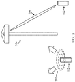
- FIG. 1 illustrates a wireless communication network 100 in accordance with various aspects of the present disclosure.
- the wireless communication network 100 may include a number of UEs 102, as well as a number of base stations 104.
- the base stations 104 may include an evolved Node B (eNodeB).
- eNodeB evolved Node B
- a base station may also be referred to as a base transceiver station, a node B, or an access point.
- a base station 104 may be a station that communicates with the UEs 102 and may also be referred to as a base station, a node B, an access point, and the like.
- the base stations 104 communicate with the UEs 102 as indicated by communication signals 106.
- a UE 102 may communicate with the base station 104 via an uplink and a downlink.
- the downlink (or forward link) refers to the communication link from the base station 104 to the UE 102.
- the uplink (or reverse link) refers to the communication link from the UE 102 to the base station 104.
- the base stations 104 may also communicate with one another, directly or indirectly, over wired and/or wireless connections, as indicated by communication signals 108.
- UEs 102 may be dispersed throughout the wireless network 100, as shown, and each UE 102 may be stationary or mobile.
- the UE 102 may also be referred to as a terminal, a mobile station, a subscriber unit, etc.
- the UE 102 may be a cellular phone, a smartphone, a personal digital assistant, a wireless modem, a laptop computer, a tablet computer, etc.
- the wireless communication network 100 is one example of a network to which various aspects of the disclosure apply.
- Each base station 104 may provide communication coverage for a particular geographic area.
- the term "cell" can refer to this particular geographic coverage area of a base station and/or a base station subsystem serving the coverage area, depending on the context in which the term is used.
- a base station 104 may provide communication coverage for a macro cell, a pico cell, a femto cell, and/or other types of cell.
- a macro cell generally covers a relatively large geographic area (e.g., several kilometers in radius) and may allow unrestricted access by UEs with service subscriptions with the network provider.
- a pico cell may generally cover a relatively smaller geographic area and may allow unrestricted access by UEs with service subscriptions with the network provider.
- a femto cell may also generally cover a relatively small geographic area (e.g., a home) and, in addition to unrestricted access, may also provide restricted access by UEs having an association with the femto cell (e.g., UEs in a closed subscriber group (CSG), UEs for users in the home, and the like).
- a base station for a macro cell may be referred to as a macro base station.
- a base station for a pico cell may be referred to as a pico base station.
- a base station for a femto cell may be referred to as a femto base station or a home base station.
- the base stations 104a, 104b and 104c are examples of macro base stations for the coverage areas 110a, 110b and 110c, respectively.
- the base stations 104d and 104e are examples of pico and/or femto base stations for the coverage areas 110d and 110e, respectively.
- a base station 104 may support one or multiple (e.g., two, three, four, and the like) cells.
- the wireless network 100 may also include relay stations.
- a relay station is a station that receives a transmission of data and/or other information from an upstream station (e.g., a base station, a UE, or the like) and sends a transmission of the data and/or other information to a downstream station (e.g., another UE, another base station, or the like).
- a relay station may also be a UE that relays transmissions for other UEs.
- a relay station may also be referred to as a relay base station, a relay UE, a relay, and the like.
- the wireless network 100 may support synchronous or asynchronous operation.
- the base stations 104 may have similar frame timing, and transmissions from different base stations 104 may be approximately aligned in time.
- the base stations 104 may have different frame timing, and transmissions from different base stations 104 may not be aligned in time.
- the wireless network 100 utilizes orthogonal frequency division multiplexing (OFDM) on the downlink and single-carrier frequency division multiplexing (SC-FDM) on the uplink.
- OFDM and SC-FDM partition the system bandwidth into multiple (K) orthogonal subcarriers, which are also commonly referred to as tones, bins, or the like.
- K orthogonal subcarriers
- Each subcarrier may be modulated with data.
- modulation symbols are sent in the frequency domain with OFDM and in the time domain with SC-FDM.
- the spacing between adjacent subcarriers may be fixed, and the total number of subcarriers (K) may be dependent on the system bandwidth.
- K may be equal to 72, 180, 300, 600, 900, and 1200 for a corresponding system bandwidth of 1.4, 3, 5, 10, 15, or 20 megahertz (MHz), respectively.
- the system bandwidth may also be partitioned into sub-bands.
- a sub-band may cover 1.08 MHz, and there may be 1, 2, 4, 8 or 16 sub-bands for a corresponding system bandwidth of 1.4, 3, 5, 10, 15, or 20MHz, respectively.
- FIG. 2 there is shown an example of a system that may be used to enhance the efficiency of use of available bandwidth in wireless communications channels between one or more UEs 102 and one or more base stations 104, as discussed above with respect to FIG. 1 .
- FIG. 2 illustrates one base station 104 and one UE 102 for purposes of simplicity of discussion, though it will be recognized that embodiments of the present disclosure may scale to many more UEs 102 and/or base stations 104.
- the UE 102 and the base station 104 may communication with each other at various frequencies. For example, in one embodiment the UE 102 and the base station 104 may communicate at sub-6 GHz frequencies, while in another embodiment at above 6 GHz frequencies, to name just two examples.
- the UE 102 broadcasts a sounding reference signal (SRS) 202 that is received by base station 104.
- the SRS 202 may be an omni-directional transmission, while in another embodiment the SRS 202 may be a wide-beam transmission.
- the base station 104 Upon receipt of the SRS 202, the base station 104 is able to gather from the SRS 202, either explicitly or implicitly, channel information for the uplink channel between the UE 102 and the base station 104. The base station 104 may then use that uplink channel information to train its antennas to beamform a downlink 204 to the same UE 102.
- the base station 104 may rapidly re-apply that information (by training) for beamforming (or focusing) a downlink transmission to the UE 102 so as to minimize the effects of channel decorrelation.
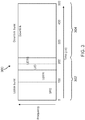
- a short subframe structure Referring now to FIG. 3 , an exemplary subframe structure 300 is illustrated that operates within a short timeframe so as to minimize the effects of decorrelation in the channel.
- the short timeframe may be approximately 500 microseconds, though it may also be shorter or longer than that.
- the short timeframe allows the base station 104 to essentially "freeze" the channel state for the duration of the subframe, during which the base station 104 may train and form the beam for the downlink and then provide a downlink burst.
- Communications between UE 102 and base station 104 can be divided in the time domain into subframes (SFs) 300, such as the SF 300 illustrated in FIG. 3 .
- SFs subframes
- a single subframe is illustrated in FIG. 3 for ease of illustration; as will be recognized, the structure of the SF 300 is scalable to any number of subframes as necessary or desired.
- Each SF 300 is divided into an uplink (UL) portion 302 and a downlink (DL) portion 304, separated by a transition portion U/D.
- the UE 102 may send various types of signals to the base station 104. These may include, for example, an SRS (used here for transmit beamforming at the base station and in place of the uplink DMRS), uplink data, and optionally requests for information.
- SRS used here for transmit beamforming at the base station and in place of the uplink DMRS
- uplink data and optionally requests for information.
- the transition portion U/D is provided between the UL portion 302 and the DL portion 304.
- the base station 104 sends various types of signals to the UE 102, including for example a user-equipment reference signal (UERS) and downlink data (e.g., in a downlink burst).
- UERS user-equipment reference signal
- downlink data e.g., in a downlink burst
- the base station 104 may use the SRS in the UL portion 302 derive multiple pieces of information that facilitate the downlink between the UE 102 and the base station 104. For example, based on the SRS the base station 104 having multiple antennas is able to train its antennas to beamform the DL data transmitted back to the UE 102 so that, for instance, interference with other wireless communication devices in the range of the base station 104 is reduced. Beamforming relies on information about the channel between the UE 102 and the base station 104 that the base station 104 derives from the uplink SRS and then applies to the downlink based on reciprocity.
- the base station 104 can retrain its antennas as the channel changes over time (e.g., periodically or randomly), for example according to subsequent SRS received from the UE 102. This may happen, for example, if the UE 102 is moving or if other moving objects enter or leave the area/ interfere with the uplink (or downlink) channel.
- the subframe 300 is provided as part of a synchronous system, such that the subframe 300 is provided repeatedly over time so that the base station 104 may retrain the beams to accommodate for UE 102 motion and channel decorrelation related to that movement (and/or other influences).
- Channel reciprocity may allow the base station 104 to apply information about the channel in the UL direction to estimate one or more channel properties in the DL direction, which can be used to beamform the DL transmissions. In this manner, the base station 104 can train its antennas based on the SRS from the UE 102.
- the SRS may further include information that allows the base station 104 to demodulate data received from the UE 102 during the UL portion of the SF 300.
- the base station 104 may additionally determine, from the SRS, scheduling information that allows the base station 104 to schedule future SFs 300 (e.g., frequency bands, etc.) for communicating with the UE 102.
- multiplexing may be used to allow the base station 104 to communicate with multiple UEs 102 during the DL portion 304 of one SF 300.
- Beamforming can be advantageous because it allows the base station 104 to make use of space division multiplexing alongside other types of multiplexing, such as frequency division multiplexing and/or code division multiplexing.
- the base station 104 may therefore request that multiple UEs 102 send an SRS during one SF 300, allowing the base station 104 to retrain its antenna beamforming for each UE 102 that it will communicate with during that SF 300.
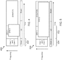
- FIG. 4 there is illustrated an embodiment of allocation of SF resources of a SF 400 in a multi-user MIMO (MU-MIMO) scenario.
- two UEs 102 are represented by SRS 1, SRS 2, for simplicity of discussion. It will be recognized that more UEs 102 may be included in various embodiments.
- Each UE 102 in the MU-MIMO system may transmit their SRS at the same time and on the same frequency allocation (i.e., using non-orthogonal physical resources) without collision by using, for example, permutation or scrambling to make each SRS unique.
- the base station 104 may request an SRS from multiple UEs 102 during the same SF 400 by sending a request during a DL portion 402 at the beginning of the SF 400.
- This request may include information instructing the UEs 102 how to scramble or permute their particular SRS (e.g., SRS 1 for a first UE 102 and SRS 2 for a second UE 102) to avoid interference.
- the UEs 102 may notice interference from other UEs 102 and decide to use a permutation, scrambling or the like to transmit an SRS using non-orthogonal physical resources.
- the UEs 102 may notify the base station 104 during the UL portion of SF 400 which permutation, scrambling or other method they will use to create a unique SRS.
- either the UEs 102 or the base station 104 may determine a minimum processing gain (PG) needed to compensate for a poor channel, for example when a UE 102 is distant from a base station 104.
- the UE 102 may determine a minimum PG by monitoring how long it takes to successfully receive a SYNC signal from the base station 104.
- the base station 104 may determine a minimum PG by monitoring how long it takes to set up a random access channel (RACH) with the UE 102.
- RACH random access channel
- the length of the SRS may need to be scaled to exceed the portion of the SF 500 allocated to the UL portion 502.
- the base station 104 may request an elongated SRS (illustrated in FIG. 5 as SRS 2) from a UE 102 during a DL portion 504 at the beginning of the SF 500, or alternatively the UE 102 may notify the base station 104 during the UL portion 502 of SF 500 that it needs to send an elongated SRS.
- the UE 102 may still be able to transmit its elongated SRS using non-orthogonal physical resources because there is no danger of its low power signal affecting other UEs 102 in the environment. Therefore, the base station 104 need not instruct other UEs 102 in the environment to modify their behavior, nor do the other UEs 102 in the environment need to proactively modify their behavior.
- a single UE 102 with multiple antennas may send an SRS from each of its antennas simultaneously and on the same frequency (i.e., using non-orthogonal physical resources) without collision by using permutation, scrambling, or a different precoder across antennas to make each SRS at each antenna unique from the others at the other antennas.
- the SF 400 of FIG. 4 (originally described with respect to single antennas on multiple UEs 102) illustrates this embodiment, as multiple antennas on a single UE 102 function similarly to single antennas on multiple UEs 102. In this case (referring now to FIG.
- the base station 104 may notify the UE 102 during a DL portion 402 at the beginning of the SF 400 how to create a unique SRS for each antenna, or alternatively the UE 102 may choose its own unique SRS for each antenna and notify the base station 104 what to look for.
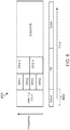
- multiple UEs 102 may send respective SRS during the same SF 600.
- the multiple UEs 102 may use unique sets of time and frequency allocations, i.e. using orthogonal physical resources, for the SRS from each respective UE 102. This may be necessary when UEs 102 are close to the base station 104, which results in very high power signals received at the base station 104, i.e. a very high UL signal-to-noise ratio (SNR).
- SNR signal-to-noise ratio
- first and second UEs 102 may each be allocated two non-contiguous pieces of frequency spectrum within a first time period (represented by SRS 1 and SRS 2, respectively), while third and fourth UEs 102 may be each allocated contiguous blocks of frequency spectrum (represented by SRS 3 and SRS 4, respectively) within a second time period.
- UEs 102 may be allocated one or more contiguous or non-contiguous blocks of spectrum over one or more contiguous or non-contiguous time periods.
- the base station 104 may recognize, for example based on a very short time to establish a RACH with the UE 102, that the power level of signals received from the UEs 102 is very high and that orthogonal resources should be used for the SRS from one or more of the UEs 102.
- the base station 104 may accordingly send instructions to the UEs 102 during a DL portion of the SF 600 allocating physical resources for the SRS of each UE 102.
- a given UE 102 may recognize that it has a very high UL SNR, for example based on a very short time to receive a SYNC signal from the base station 104, and may notify the base station 104 that the UE 102 needs its own allocation of physical resources for its SNR.
- the UE 102 may suggest a potential allocation to the base station 104.
- a single UE 102 with multiple antennas may send an SRS from each of its antennas during the same SF 600, but using unique sets of time and frequency allocations, i.e. using orthogonal physical resources.
- first and second antennas of UE 102 may each be allocated two non-contiguous pieces of frequency spectrum within a first time period (represented by SRS 1 and SRS 2, respectively), while third and fourth antennas of UE 102 may be allocated a single contiguous block of frequency spectrum within a second time period (represented by SRS 3 and SRS 4, respectively).
- the base station 104 may notify the UE 102 during a DL portion 602 at the beginning of the SF 600 of resource allocations for each antenna, or alternatively the UE 102 may choose its own resource allocations for each antenna and notify the base station 104 what to look for.
- a UE 102 has a narrowband power amplifier (PA).
- PA narrowband power amplifier
- the SRS may need to cover the entire system bandwidth. If the UE 102 has a narrowband PA, it can only cover a sub-band of the system bandwidth with any given transmission. As illustrated in frame structure 700, the UE 102 may transmit multiple consecutive narrowband SRS at staggered frequencies that, together, cover the entire system bandwidth. The base station 104 may collect and combine the multiple consecutive narrowband SRS to obtain complete information about the system bandwidth of the downlink channel.
- the UE 102 may accordingly transmit only as many staggered narrowband SRS as necessary to reach the threshold for channel reciprocity, as illustrated by SF structure 800.
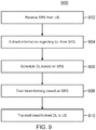
- FIG. 9 is a flowchart illustrating an exemplary method 900 for using an uplink sounding reference signal for channel estimation in accordance with various aspects of the present disclosure.
- the method 900 may be implemented in the base station 104.
- the method 900 will be described with respect to a single base station 104 for simplicity of discussion, though it will be recognized that the aspects described herein may be applicable to any number of base stations 104. It is understood that additional method blocks can be provided before, during, and after the blocks of method 900, and that some of the blocks described can be replaced or eliminated for other embodiments of the method 900.
- a base station 104 receives an SRS from a UE 102 in an uplink communication, as described according to the various embodiments above.
- the base station 104 may receive the SRS as part of an uplink portion of a subframe as illustrated in FIG. 3 .
- the base station 102 may receive a single SRS from a single-antenna UE 102, multiple SRS corresponding to multiple antennas of a single UE 102, multiple SRS corresponding to single antennas of multiple UEs 102, and/or multiple SRS corresponding to multiple antennas of multiple UEs 102.
- the SRS may be provided to the base station 104 according to non-orthogonal or orthogonal SRS, depending upon embodiment.
- the base station 104 extracts information about the uplink from the SRS received at block 902. This may include information useful in demodulating uplink data including in the uplink portion of the subframe, scheduling information, and channel information about the uplink channel.
- the base station 104 schedules the downlink communication (e.g., the downlink burst that is part of the downlink portion of a subframe), based on information extracted from the SRS at block 904.
- the downlink communication e.g., the downlink burst that is part of the downlink portion of a subframe
- the base station 104 trains the beamforming for the one or more antennas of the base station 104 based on channel information extracted from the SRS received from the UE 102. Based on the SRS, the beamforming may be invariant to the number of antennas within the system, rendering embodiments of the present disclosure forward-compatible with future technologies that include more antennas (e.g., 16, 32, etc.) in MIMO arrays for example.
- the base station 104 transmits a downlink burst including one or more reference signals (such as a UERS) as well as downlink data.
- one or more reference signals such as a UERS
- the base station 104 With the beam forms of the antennas of the base station 104 trained based on the channel information derived from the uplink SRS, applied to the downlink by taking advantage of reciprocity during a short timeframe encapsulated by the subframe, the base station 104 is able to more improve its utilization of higher frequencies while still providing a substantially equivalent range that is possible with lower frequencies/evolution technologies (2G, 3G, 4G for example).
- method 900 may be implemented in program code stored on a computer readable medium.
- the program code may, for example, cause a processor to implement the blocks 902-910 upon reading the code from the computer readable medium.
- the UE 102 and base station 104 of the present disclosure may include such a processor and such a computer readable medium with program code stored in it.
- FIG. 10 a flowchart is illustrated of an exemplary method 1000 for using a non-orthogonal uplink sounding reference signal for channel estimation in accordance with various aspects of the present disclosure.
- the method 1000 may be implemented in a UE 102.
- the method 1000 described is applicable to both single UEs 102 having multiple antennas and multiple UEs 102 that each have single antennas. It is understood that additional method blocks can be provided before, during, and after the blocks of method 1000, and that some of the blocks described can be replaced or eliminated for other embodiments of the method 1000.
- the UE 102 monitors the interference level. For a single UE 102 having multiple antennas, this involves monitoring the interference level at each antenna of the UE 102. For multiple UEs 102 that each have a single antenna, this involves each UE 102 monitoring the interference level of its antenna.
- the UE 102 determines whether a permutation (interleaving) or a scrambling code will better overcome the interference monitored at block 1002. For example, this may involve the UE 102 determining to use non-orthogonal coding where the UE 102 is power limited (e.g., the uplink SNR is low) or to enable MU-MIMO on the downlink (e.g., where the multiple UEs 102 each have multiple antennas).
- the UE 102 configures the SRS for each of its antennas (or, for single-antenna UEs 102, each UE 102 for its respective antenna) with the unique permutation or scrambling code, as determined at block 1004.
- the UE 102 With the SRS (of each antenna for a MIMO UE 102 or each antenna for each UE 102, depending upon embodiment) scrambled, at block 1008 the UE 102 (each SRS for each antenna or each UE 102) transmits the scrambled SRS to the base station 104 via the uplink channel.
- the transmission may be done using the full channel bandwidth and the full uplink subframe portion (as discussed with respect to FIG. 3 above).
- the base station 104 After the base station 104 receives the SRS in the uplink portion of the subframe from the multiple antennas of the UE 102 (or each antenna of each UE 102, depending upon the embodiment), the base station 104 derives channel state information from the SRS for the uplink channel and, based on reciprocity, applies the derived channel state information to the downlink channel. This includes training the beamform for the antennas of the base station 104 toward the UE 102.
- the UE 102 receives a beamformed downlink burst from the base station 104 (at the multiple antennas of a single UE 102 or at each antenna of each UE 102 of many) as part of the downlink portion of the same subframe.
- method 1000 may be implemented in program code stored on a computer readable medium.
- the program code may, for example, cause a processor to implement the blocks 1002-1010 upon reading the code from the computer readable medium.
- the UE 102 and base station 104 of the present disclosure may include such a processor and such a computer readable medium with program code stored in it.
- FIG. 11 illustrates a flowchart of an exemplary method 1100 for using an orthogonal uplink sounding reference signal for channel estimation in accordance with various aspects of the present disclosure.
- the method 1100 may be implemented in a UE 102.
- the method 1100 described is applicable to both single UEs 102 having multiple antennas and multiple UEs 102 that each have single antennas. It is understood that additional method blocks can be provided before, during, and after the blocks of method 1100, and that some of the blocks described can be replaced or eliminated for other embodiments of the method 1100.
- the UE 102 monitors the interference level. For a single UE 102 having multiple antennas, this involves monitoring the interference level at each antenna of the UE 102. For multiple UEs 102 that each have a single antenna, this involves each UE 102 monitoring the interference level of its antenna, as described above with respect to FIG. 10 .
- the UE 102 determines whether the uplink SNR is sufficiently high to allow the SRS to be orthogonal - where each SRS at each antenna (either at a single UE 102 or multiple UEs 102) is allocated a different time/frequency combination physical resource.
- the UE 102 configures the SRS for each of its antennas (or, for single-antenna UEs 102, each UE 102 for its respective antenna) with particular frequency/time combinations.
- the frequency which each SRS is allocated may be contiguous to other frequencies assigned to other SRS or may be staggered across tones.
- the UE 102 With the SRS of each antenna for a MIMO UE 102 (or each antenna for each UE 102, depending upon embodiment) assigned a different frequency/time physical resource, at block 1108 the UE 102 (each SRS for each antenna or each UE 102) transmits the SRS to the base station 104 via the uplink channel using the unique frequency/time physical resources.
- the base station 104 After the base station 104 receives the SRS in the uplink portion of the subframe from the multiple antennas of the UE 102 (or each antenna of each UE 102, depending upon the embodiment), the base station 104 derives channel state information from the SRS for the uplink channel and, based on reciprocity, applies the derived channel state information to the downlink channel. This includes training the beamform for the antennas of the base station 104 toward the UE 102.
- the UE 102 receives a beamformed downlink burst from the base station 104 (at the multiple antennas of a single UE 102 or at each antenna of each UE 102 of many) as part of the downlink portion of the same subframe.
- method 1100 may be implemented in program code stored on a computer readable medium.
- the program code may, for example, cause a processor to implement the blocks 1102-1110 upon reading the code from the computer readable medium.
- the UE 102 and base station 104 of the present disclosure may include such a processor and such a computer readable medium with program code stored in it.
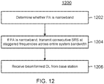
- FIG. 12 a flowchart is illustrated of an exemplary method 1200 for using an uplink sounding reference signal for channel estimation in accordance with various aspects of the present disclosure.
- the method 1200 may be implemented in a UE 102 that has a narrowband power amplifier. It is understood that additional method blocks can be provided before, during, and after the blocks of method 1200, and that some of the blocks described can be replaced or eliminated for other embodiments of the method 1200.
- the UE 102 determines whether the power amplifier is narrowband. As described above, a narrowband power amplifier may only cover a sub-band of the system bandwidth with any given transmission.
- the UE 102 in response to determining that the power amplifier of the UE 102 is narrowband, the UE 102 generates and transmits a series of consecutive SRS that are staggered across frequencies across a large portion of or the entire system bandwidth, for example as illustrated in FIG. 7 , as part of the uplink portion of a subframe according to the embodiments discussed above.
- the base station 104 receives the consecutive SRS (in time, staggered across frequencies) and combines to obtain a substantially full view of the uplink channel information.
- the base station 104 uses reciprocity, then in turn applies the channel information to the downlink channel and beamforms the antennas accordingly.
- the UE 102 receives the beamformed downlink burst as part of the same subframe from the base station 104.
- method 1200 may be implemented in program code stored on a computer readable medium.
- the program code may, for example, cause a processor to implement the blocks 1202-1206 upon reading the code from the computer readable medium.
- the UE 102 and base station 104 of the present disclosure may include such a processor and such a computer readable medium with program code stored in it.
- FIG. 13 is a block diagram of an exemplary wireless communication device 1300 according to embodiments of the present disclosure.
- the wireless communication device 1300 may be a UE 102 as discussed above.
- the UE 102 may include a processor 1302, a memory 1304, an SRS configuration module 1308, a transceiver 1310 (including a modem 1312 and RF unit 1314), and an antenna 1316. These elements may be in direct or indirect communication with each other, for example via one or more buses.
- the processor 1302 may include a central processing unit (CPU), a digital signal processor (DSP), an application-specific integrated circuit (ASIC), a controller, a field programmable gate array (FPGA) device, another hardware device, a firmware device, or any combination thereof configured to perform the operations described herein with reference to UEs 102 introduced above with respect to FIG. 1 and discussed in more detail above.
- the processor 1302 may be utilized in combination with the other components of the UE 102, including correlation information module 1308, to perform the various functions associated with orthogonal or scrambled SRS as described in greater detail above.
- the processor 1302 may also be implemented as a combination of computing devices, e.g., a combination of a DSP and a microprocessor, a plurality of microprocessors, one or more microprocessors in conjunction with a DSP core, or any other such configuration.
- the memory 1304 may include a cache memory (e.g., a cache memory of the processor 1302), random access memory (RAM), magnetoresistive RAM (MRAM), read-only memory (ROM), programmable read-only memory (PROM), erasable programmable read only memory (EPROM), electrically erasable programmable read only memory (EEPROM), flash memory, solid state memory device, hard disk drives, other forms of volatile and non-volatile memory, or a combination of different types of memory.
- the memory 1304 includes a non-transitory computer-readable medium.
- the memory 1304 may store instructions 1306.
- the instructions 1306 may include instructions that, when executed by the processor 1302, cause the processor 1302 to perform the operations described herein with reference to the UEs 102 in connection with embodiments of the present disclosure. Instructions 1306 may also be referred to as code.
- the terms "instructions” and “code” should be interpreted broadly to include any type of computer-readable statement(s). For example, the terms “instructions” and “code” may refer to one or more programs, routines, sub-routines, functions, procedures, etc. "Instructions" and “code” may include a single computer-readable statement or many computer-readable statements.
- the SRS configuration module 1308 may be used for various aspects of the present disclosure. For example, the SRS configuration module 1308 may be used to measure interference at the antenna or antennas of the UE 102. In one embodiment, the SRS configuration module 1308 may then determine whether permutation or scrambling will overcome the measured interference, and configure an SRS for each antenna with unique permutation or scrambling. In another embodiment, the SRS configuration module 1308 may determine whether use of orthogonal time and frequency resources (i.e. physical channel resources) for SRS transmission is necessary, and it may configure each antenna of the UE 102 to use orthogonal time and frequency resources for SRS transmission.
- orthogonal time and frequency resources i.e. physical channel resources
- the transceiver 1310 may include the modem subsystem 1312 and the radio frequency (RF) unit 1314.
- the transceiver 1310 can be configured to communicate bi-directionally with other devices, such as base stations 104.
- the modem subsystem 1312 may be configured to modulate and/or encode the data from the correlation information 1308 and other aspects of the UE 102, such as processor 1302 and/or memory 1304, according to a modulation and coding scheme (MCS), e.g., a low-density parity check (LDPC) coding scheme, a turbo coding scheme, a convolutional coding scheme, etc.
- MCS modulation and coding scheme
- LDPC low-density parity check
- the RF unit 1314 may be configured to process (e.g., perform analog to digital conversion or digital to analog conversion, etc.) modulated/encoded data from the modem subsystem 1312 (on outbound transmissions) or of transmissions originating from another source such as a UE 102 or a base station 104. Although shown as integrated together in transceiver 1310, the modem subsystem 1312 and the RF unit 1314 may be separate devices that are coupled together at the UE 102 to enable the UE 102 to communicate with other devices.
- process e.g., perform analog to digital conversion or digital to analog conversion, etc.
- the RF unit 1314 may provide the modulated and/or processed data, e.g. data packets (or, more generally, data messages that may contain one or more data packets and other information), to the antenna 1316 for transmission to one or more other devices. This may include, for example, transmission of ... according to embodiments of the present disclosure.
- the antenna 1316 may further receive data messages transmitted from other devices and provide the received data messages for processing and/or demodulation at the transceiver 1310.
- FIG. 13 illustrates antenna 1316 as a single antenna, antenna 1316 may include multiple antennas of similar or different designs in order to sustain multiple transmission links.
- FIG. 14 illustrates a block diagram of an exemplary base station 104 according to the present disclosure.
- the base station 104 may include a processor 1402, a memory 1404, a beamforming module 1408, a transceiver 1410 (including a modem 1412 and RF unit 1414), and an antenna 1416. These elements may be in direct or indirect communication with each other, for example via one or more buses.
- the processor 1402 may have various features as a specific-type processor. For example, these may include a CPU, a DSP, an ASIC, a controller, a FPGA device, another hardware device, a firmware device, or any combination thereof configured to perform the operations described herein with reference to the base stations 104 introduced in FIG. 1 above.
- the processor 1402 may also be implemented as a combination of computing devices, e.g., a combination of a DSP and a microprocessor, a plurality of microprocessors, one or more microprocessors in conjunction with a DSP core, or any other such configuration.
- the memory 1404 may include a cache memory (e.g., a cache memory of the processor 1402), RAM, MRAM, ROM, PROM, EPROM, EEPROM, flash memory, a solid state memory device, one or more hard disk drives, memristor-based arrays, other forms of volatile and non-volatile memory, or a combination of different types of memory.
- the memory 1404 may include a non-transitory computer-readable medium.
- the memory 1404 may store instructions 1406.
- the instructions 1406 may include instructions that, when executed by the processor 1402, cause the processor 1402 to perform operations described herein with reference to a base station 104 in connection with embodiments of the present disclosure. Instructions 1406 may also be referred to as code, which may be interpreted broadly to include any type of computer-readable statement(s).
- the beamforming module 1408 may be used for various aspects of the present disclosure.
- the beamforming module 1408 may be involved in extracting information from a SRS received from a UE 102 and using the extracted information to train beamforming for the one or more antennas 1416 for a downlink with the UE 102.
- the transceiver 1410 may include the modem subsystem 1412 and the radio frequency (RF) unit 1414.
- the transceiver 1410 can be configured to communicate bi-directionally with other devices, such as UE 102 and/or another core network element.
- the modem subsystem 1412 may be configured to modulate and/or encode data according to a MCS, e.g., a LDPC coding scheme, a turbo coding scheme, a convolutional coding scheme, etc.
- the RF unit 1414 may be configured to process (e.g., perform analog to digital conversion or digital to analog conversion, etc.) modulated/encoded data from the modem subsystem 1412 (on outbound transmissions) or of transmissions originating from another source such as a UE 102. Although shown as integrated together in transceiver 1410, the modem subsystem 1412 and the RF unit 1414 may be separate devices that are coupled together at the base station 104 to enable the base station 104 to communicate with other devices.
- process e.g., perform analog to digital conversion or digital to analog conversion, etc.
- the RF unit 1414 may provide the modulated and/or processed data, e.g. data packets (or, more generally, data messages that may contain one or more data packets and other information), to the antenna 1416 for transmission to one or more other devices. This may include, for example, use of beamforming to transmit information to a UE 102 according to embodiments of the present disclosure.
- the antenna 1416 may further receive data messages transmitted from other devices and provide the received data messages for processing and/or demodulation at the transceiver 1410.
- FIG. 14 illustrates antenna 1416 as a single antenna, antenna 1416 may include multiple antennas of similar or different designs in order to sustain multiple transmission links.
- Information and signals may be represented using any of a variety of different technologies and techniques.
- data, instructions, commands, information, signals, bits, symbols, and chips that may be referenced throughout the above description may be represented by voltages, currents, electromagnetic waves, magnetic fields or particles, optical fields or particles, or any combination thereof.
- a general-purpose processor may be a microprocessor, but in the alternative, the processor may be any conventional processor, controller, microcontroller, or state machine.
- a processor may also be implemented as a combination of computing devices (e.g., a combination of a DSP and a microprocessor, multiple microprocessors, one or more microprocessors in conjunction with a DSP core, or any other such configuration).
- the functions described herein may be implemented in hardware, software executed by a processor, firmware, or any combination thereof. If implemented in software executed by a processor, the functions may be stored on or transmitted over as one or more instructions or code on a computer-readable medium. Other examples and implementations are within the scope of the disclosure and appended claims. For example, due to the nature of software, functions described above can be implemented using software executed by a processor, hardware, firmware, hardwiring, or combinations of any of these. Features implementing functions may also be physically located at various positions, including being distributed such that portions of functions are implemented at different physical locations.
Landscapes
- Engineering & Computer Science (AREA)
- Signal Processing (AREA)
- Computer Networks & Wireless Communication (AREA)
- Mobile Radio Communication Systems (AREA)
- Time-Division Multiplex Systems (AREA)
Priority Applications (1)
| Application Number | Priority Date | Filing Date | Title |
|---|---|---|---|
| EP20168172.3A EP3700099B1 (en) | 2015-03-14 | 2016-02-05 | Reciprocal channel sounding reference signal multiplexing |
Applications Claiming Priority (3)
| Application Number | Priority Date | Filing Date | Title |
|---|---|---|---|
| US201562133334P | 2015-03-14 | 2015-03-14 | |
| US14/866,778 US9847862B2 (en) | 2015-03-14 | 2015-09-25 | Reciprocal channel sounding reference signal multiplexing |
| PCT/US2016/016723 WO2016148795A1 (en) | 2015-03-14 | 2016-02-05 | Reciprocal channel sounding reference signal multiplexing |
Related Child Applications (2)
| Application Number | Title | Priority Date | Filing Date |
|---|---|---|---|
| EP20168172.3A Division-Into EP3700099B1 (en) | 2015-03-14 | 2016-02-05 | Reciprocal channel sounding reference signal multiplexing |
| EP20168172.3A Division EP3700099B1 (en) | 2015-03-14 | 2016-02-05 | Reciprocal channel sounding reference signal multiplexing |
Publications (2)
| Publication Number | Publication Date |
|---|---|
| EP3272021A1 EP3272021A1 (en) | 2018-01-24 |
| EP3272021B1 true EP3272021B1 (en) | 2020-05-13 |
Family
ID=56888314
Family Applications (2)
| Application Number | Title | Priority Date | Filing Date |
|---|---|---|---|
| EP16706473.2A Active EP3272021B1 (en) | 2015-03-14 | 2016-02-05 | Reciprocal channel sounding reference signal multiplexing |
| EP20168172.3A Active EP3700099B1 (en) | 2015-03-14 | 2016-02-05 | Reciprocal channel sounding reference signal multiplexing |
Family Applications After (1)
| Application Number | Title | Priority Date | Filing Date |
|---|---|---|---|
| EP20168172.3A Active EP3700099B1 (en) | 2015-03-14 | 2016-02-05 | Reciprocal channel sounding reference signal multiplexing |
Country Status (11)
Families Citing this family (56)
| Publication number | Priority date | Publication date | Assignee | Title |
|---|---|---|---|---|
| US9847862B2 (en) | 2015-03-14 | 2017-12-19 | Qualcomm Incorporated | Reciprocal channel sounding reference signal multiplexing |
| CN106160838B (zh) * | 2015-04-16 | 2020-02-07 | 电信科学技术研究院 | 一种传输数据的方法和设备 |
| CN106953676A (zh) | 2016-01-07 | 2017-07-14 | 索尼公司 | 无线通信方法和无线通信设备 |
| US10912090B2 (en) * | 2016-04-10 | 2021-02-02 | Lg Electronics Inc. | Method and device for transmitting uplink reference signal in wireless communication system |
| JP6891419B2 (ja) | 2016-07-29 | 2021-06-18 | ソニーグループ株式会社 | 端末装置、基地局、方法及び記録媒体 |
| WO2018043997A1 (ko) * | 2016-08-28 | 2018-03-08 | 엘지전자 주식회사 | 다중화된 상향링크 제어 채널 및 국부적인 사운딩 참조 심볼의 전송 및 수신 방법과 이를 위한 장치 |
| US10201020B2 (en) * | 2016-09-19 | 2019-02-05 | National Instruments Corporation | Multi-user random access procedures for massive MIMO wireless communication systems |
| US10903877B2 (en) * | 2016-11-03 | 2021-01-26 | Mediatek Inc. | Initial access procedure for multi-beam operation |
| US10362571B2 (en) * | 2016-11-04 | 2019-07-23 | Qualcomm Incorporated | Power control and triggering of sounding reference signal on multiple component carriers |
| JP7076202B2 (ja) * | 2016-12-28 | 2022-05-27 | パナソニック インテレクチュアル プロパティ コーポレーション オブ アメリカ | 通信方法、無線端末装置、および集積回路 |
| RU2717948C1 (ru) * | 2016-12-28 | 2020-03-27 | Панасоник Интеллекчуал Проперти Корпорэйшн оф Америка | Способ связи для использования беспроводного устройства терминала, способ связи для использования беспроводного устройства базовой станции, беспроводное устройство терминала и беспроводное устройство базовой станции |
| KR20190116396A (ko) * | 2017-02-06 | 2019-10-14 | 광동 오포 모바일 텔레커뮤니케이션즈 코포레이션 리미티드 | 통신 방법, 단말 장치 및 네트워크 장치 |
| US11152981B2 (en) * | 2017-03-17 | 2021-10-19 | Sony Group Corporation | Operating a terminal device and a base station in a wireless MIMO system |
| CN108633046B (zh) * | 2017-03-24 | 2023-08-22 | 华为技术有限公司 | 传输信号的方法和装置 |
| US10743319B2 (en) * | 2017-05-01 | 2020-08-11 | Qualcomm Incorporated | Method of base station beam refinement |
| EP3598660B1 (en) * | 2017-05-04 | 2021-08-25 | Huawei Technologies Co., Ltd. | Method and terminal device for transmitting reference signal |
| US10841062B2 (en) * | 2017-05-04 | 2020-11-17 | Qualcomm Incorporated | Sequence for reference signals during beam refinement |
| CN109150431A (zh) | 2017-06-15 | 2019-01-04 | 株式会社Ntt都科摩 | 一种探测参考信号传输方法、基站和用户设备 |
| CN109392110B (zh) * | 2017-08-08 | 2020-05-26 | 维沃移动通信有限公司 | 一种指示上行传输的方法及装置 |
| RU2735715C1 (ru) * | 2017-08-10 | 2020-11-06 | ЗедТиИ КОРПОРЕЙШН | Системы и способы для указания и определения информации структуры канала |
| US10834689B2 (en) | 2017-08-15 | 2020-11-10 | At&T Intellectual Property I, L.P. | Base station wireless channel sounding |
| US10638340B2 (en) | 2017-08-15 | 2020-04-28 | At&T Intellectual Property I, L.P. | Base station wireless channel sounding |
| US11343124B2 (en) | 2017-08-15 | 2022-05-24 | At&T Intellectual Property I, L.P. | Base station wireless channel sounding |
| US10432330B2 (en) | 2017-08-15 | 2019-10-01 | At&T Intellectual Property I, L.P. | Base station wireless channel sounding |
| US10707939B2 (en) | 2017-10-03 | 2020-07-07 | Mediatek Inc. | Codebook-based uplink transmission in wireless communications |
| TWI704780B (zh) * | 2017-10-03 | 2020-09-11 | 聯發科技股份有限公司 | 無線通訊中基於碼本之上行鏈路傳輸方法 |
| US11032721B2 (en) | 2017-10-13 | 2021-06-08 | At&T Intellectual Property I, L.P. | Minimization of drive tests in beamformed wireless communication systems |
| US10091662B1 (en) | 2017-10-13 | 2018-10-02 | At&T Intellectual Property I, L.P. | Customer premises equipment deployment in beamformed wireless communication systems |
| EP3669600A4 (en) * | 2017-10-26 | 2021-03-17 | Lenovo (Beijing) Limited | DETERMINATION OF INFORMATION CORRESPONDING TO A BEAM TRAINING |
| WO2019176468A1 (ja) * | 2018-03-14 | 2019-09-19 | 日本電気株式会社 | 基地局、方法、プログラム、及び記録媒体 |
| US11032048B2 (en) * | 2018-05-18 | 2021-06-08 | Qualcomm Incorporated | Use-cases and constraints on multiple SRS resource sets for antenna switching in NR REL-15 |
| EP3876432A4 (en) * | 2018-10-31 | 2022-06-29 | NTT DoCoMo, Inc. | User equipment |
| CN113196865A (zh) * | 2018-12-14 | 2021-07-30 | 株式会社Ntt都科摩 | 用户终端以及无线通信方法 |
| CN111405663A (zh) * | 2019-01-03 | 2020-07-10 | 索尼公司 | 用于无线通信的电子设备和方法、计算机可读存储介质 |
| CN111669205B (zh) * | 2019-03-07 | 2021-08-17 | 荣耀终端有限公司 | 一种信道测量方法及设备 |
| CN110167119B (zh) * | 2019-06-14 | 2022-03-29 | Oppo广东移动通信有限公司 | 射频电路及电子设备 |
| CN110350961A (zh) * | 2019-07-15 | 2019-10-18 | 福州数据技术研究院有限公司 | 适于5g多用户大规模mimo混合波束赋形算法及系统 |
| KR102257505B1 (ko) | 2019-07-25 | 2021-05-31 | 한양대학교 산학협력단 | 비 직교 다중 접속을 지원하는 무선 통신 시스템에서 위치 기반 전력 할당 장치 및 방법 |
| US11082265B2 (en) | 2019-07-31 | 2021-08-03 | At&T Intellectual Property I, L.P. | Time synchronization of mobile channel sounding system |
| CN112584484B (zh) * | 2019-09-30 | 2022-06-07 | 华为技术有限公司 | 信号发送和处理方法及装置 |
| US11716701B2 (en) * | 2019-10-02 | 2023-08-01 | Qualcomm Incorporated | Estimating and reporting of side-information for enhanced reciprocal signaling-based positioning |
| US11350269B2 (en) * | 2019-10-31 | 2022-05-31 | Qualcomm Incorporated | Antenna correlation feedback for partial reciprocity |
| WO2021109135A1 (en) | 2019-12-06 | 2021-06-10 | Telefonaktiebolaget Lm Ericsson (Publ) | Method and access network node for beam control |
| CN113300823A (zh) * | 2020-02-21 | 2021-08-24 | 维沃移动通信有限公司 | Srs的传输方法、码本传输方法、装置、终端及介质 |
| US11411779B2 (en) | 2020-03-31 | 2022-08-09 | XCOM Labs, Inc. | Reference signal channel estimation |
| BR112022022636A2 (pt) * | 2020-05-08 | 2022-12-13 | Ericsson Telefon Ab L M | Receptor de sistema de antena avançado, método em um receptor de sistema de antena avançado, e, estação base configurada para se comunicar com um equipamento de usuário |
| US12362810B2 (en) | 2020-05-11 | 2025-07-15 | Telefonaktiebolaget Lm Ericsson (Publ) | Efficient PRACH scheduling |
| KR102402857B1 (ko) * | 2020-08-13 | 2022-05-26 | 주식회사 엘지유플러스 | 사운딩 참조 신호 대역폭 결정 방법 및 장치 |
| EP4229846A4 (en) | 2020-10-19 | 2024-12-11 | Xcom Labs, Inc. | REFERENCE SIGNAL FOR WIRELESS COMMUNICATION SYSTEMS |
| WO2022093988A1 (en) | 2020-10-30 | 2022-05-05 | XCOM Labs, Inc. | Clustering and/or rate selection in multiple-input multiple-output communication systems |
| JP7545301B2 (ja) | 2020-11-18 | 2024-09-04 | Kddi株式会社 | 複数のビーム形成手法を用いて通信する通信装置、通信方法、およびプログラム |
| JP7544571B2 (ja) | 2020-11-18 | 2024-09-03 | Kddi株式会社 | 複数のビーム形成手法を用いて通信する通信装置、通信方法、およびプログラム |
| CN112822785B (zh) * | 2021-01-14 | 2024-07-19 | 上海移远通信技术股份有限公司 | 数据传输的方法及装置、系统、可读存储介质 |
| WO2022241436A1 (en) | 2021-05-14 | 2022-11-17 | XCOM Labs, Inc. | Scrambling identifiers for wireless communication systems |
| CN113938168B (zh) * | 2021-12-16 | 2022-03-04 | 广东省新一代通信与网络创新研究院 | 上下行非对称通信mimo系统的劈裂波束管理方法及系统 |
| CN117202355A (zh) * | 2022-05-27 | 2023-12-08 | 华为技术有限公司 | 资源配置方法及通信装置 |
Family Cites Families (31)
| Publication number | Priority date | Publication date | Assignee | Title |
|---|---|---|---|---|
| US6377636B1 (en) | 1999-11-02 | 2002-04-23 | Iospan Wirless, Inc. | Method and wireless communications system using coordinated transmission and training for interference mitigation |
| US8099132B2 (en) * | 2007-08-15 | 2012-01-17 | Qualcomm Incorporated | Antenna switching and uplink sounding channel measurement |
| KR101639810B1 (ko) * | 2009-01-13 | 2016-07-25 | 엘지전자 주식회사 | 무선통신 시스템에서 사운딩 참조신호의 전송방법 |
| CN101867938B (zh) * | 2009-04-20 | 2013-01-02 | 电信科学技术研究院 | 一种用于多点协同传输的上行参考信号的配置方法和装置 |
| US8548406B2 (en) * | 2009-05-05 | 2013-10-01 | Lg Electronics Inc. | Method of transmitting reference signal in multiple antenna system |
| KR101652248B1 (ko) * | 2010-02-11 | 2016-08-30 | 주식회사 팬택 | 채널추정 기준신호의 주기/비주기 전송 스위칭 방법, 그를 이용한 채널추정 기준신호의 송수신 장치 및 방법 |
| CN102088303B (zh) * | 2010-02-11 | 2014-11-05 | 电信科学技术研究院 | Srs信号发送方法及其触发方法以及设备 |
| US9820273B2 (en) * | 2010-03-02 | 2017-11-14 | Xiaoxia Zhang | Uplink coordinated multipoint communications in a wireless network |
| WO2011126351A2 (ko) * | 2010-04-09 | 2011-10-13 | 엘지전자 주식회사 | 경쟁 기반의 상향링크 채널 신호 송수신 방법 |
| CN102223167B (zh) * | 2010-04-16 | 2015-11-25 | 华为技术有限公司 | 多天线系统中的探测参考信号发送方法及装置 |
| US8917687B2 (en) * | 2010-04-20 | 2014-12-23 | China Mobile Communications Corporation | Method, apparatus and system for sending and receiving sounding reference signal |
| WO2011134532A1 (en) | 2010-04-30 | 2011-11-03 | Nokia Siemens Networks Oy | Multiplexing of sounding reference signal with pucch |
| US8891462B2 (en) | 2010-05-14 | 2014-11-18 | Qualcomm Incorporated | Methods and apparatuses for downlink channel resource assignment |
| US8761097B2 (en) * | 2010-05-19 | 2014-06-24 | Qualcomm Incorporated | Systems and methods for enhancing uplink coverage in interference scenerios |
| CN102377714A (zh) | 2010-08-12 | 2012-03-14 | 普天信息技术研究院有限公司 | 一种增强上行侦听参考信号的方法和装置 |
| US20160008108A1 (en) * | 2010-11-03 | 2016-01-14 | Timothy C. Thompson | System and Processes for Optimization for Dentures |
| CN102065557B (zh) * | 2010-12-31 | 2016-03-30 | 中兴通讯股份有限公司 | 用于协作多点传输系统的测量参考信号发送方法及系统 |
| RU2587651C2 (ru) * | 2011-02-07 | 2016-06-20 | Телефонактиеболагет Л М Эрикссон (Пабл) | Выбор базовой станции (антенны) для передачи по восходящей линии связи зондирующих опорных сигналов, srs |
| US20130265960A1 (en) | 2011-02-28 | 2013-10-10 | Nec (China) Co., Ltd. | Method and apparatus for modifying channel quality indication |
| JP5663349B2 (ja) | 2011-03-01 | 2015-02-04 | 京セラ株式会社 | 基地局及び通信システム |
| CN102761968B (zh) | 2011-04-27 | 2017-03-01 | 艾利森电话股份有限公司 | 多用户设备的探测参考信号上行资源分配方法及基站 |
| JP5707231B2 (ja) | 2011-05-27 | 2015-04-22 | 京セラ株式会社 | 基地局及び無線リソースの割り当て方法 |
| CN102427608B (zh) * | 2011-12-06 | 2015-07-01 | 电信科学技术研究院 | 一种发送srs和指示srs发送的方法及设备 |
| WO2014019213A1 (en) * | 2012-08-03 | 2014-02-06 | Qualcomm Incorporated | Subframe configurations for lte tdd systems |
| US9596065B2 (en) * | 2012-10-24 | 2017-03-14 | Qualcomm Incorporated | Enhanced SRS transmission for MIMO operation in LTE-A |
| CN103905104B (zh) * | 2012-12-28 | 2017-12-19 | 中兴通讯股份有限公司 | 一种根据探测参考信号的多天线发送方法及终端及基站 |
| WO2014109686A1 (en) | 2013-01-14 | 2014-07-17 | Telefonaktiebolaget L M Ericsson (Publ) | A user equipment, a network node and respective method therein for transmitting sounding reference signals |
| WO2014132963A1 (ja) * | 2013-02-26 | 2014-09-04 | 株式会社フジクラ | フォトニックバンドギャップファイバ用母材の製造方法、フォトニックバンドギャップファイバの製造方法、フォトニックバンドギャップファイバ用母材、及び、フォトニックバンドギャップファイバ |
| US9775151B2 (en) * | 2014-07-21 | 2017-09-26 | Intel IP Corporation | System and method for TDD communications |
| US9420584B2 (en) * | 2014-09-17 | 2016-08-16 | Telefonaktiebolaget Lm Ericsson (Publ) | Uplink sounding reference signals for machine type communications (MTC) user equipment (UE) |
| US9847862B2 (en) | 2015-03-14 | 2017-12-19 | Qualcomm Incorporated | Reciprocal channel sounding reference signal multiplexing |
-
2015
- 2015-09-25 US US14/866,778 patent/US9847862B2/en active Active
-
2016
- 2016-02-05 HU HUE16706473A patent/HUE050615T2/hu unknown
- 2016-02-05 BR BR112017019622-0A patent/BR112017019622B1/pt active IP Right Grant
- 2016-02-05 JP JP2017547549A patent/JP6686037B2/ja active Active
- 2016-02-05 CN CN202310213487.0A patent/CN116471001A/zh active Pending
- 2016-02-05 ES ES16706473T patent/ES2811998T3/es active Active
- 2016-02-05 WO PCT/US2016/016723 patent/WO2016148795A1/en active Application Filing
- 2016-02-05 CN CN202010381029.4A patent/CN111555852B/zh active Active
- 2016-02-05 KR KR1020177025516A patent/KR102663368B1/ko active Active
- 2016-02-05 AU AU2016233882A patent/AU2016233882B2/en active Active
- 2016-02-05 EP EP16706473.2A patent/EP3272021B1/en active Active
- 2016-02-05 CN CN201680015185.0A patent/CN107431595B/zh active Active
- 2016-02-05 EP EP20168172.3A patent/EP3700099B1/en active Active
- 2016-03-07 TW TW105106937A patent/TWI703878B/zh active
-
2017
- 2017-11-13 US US15/811,289 patent/US10389503B2/en active Active
-
2019
- 2019-08-12 US US16/538,548 patent/US11374711B2/en active Active
-
2020
- 2020-03-31 JP JP2020063004A patent/JP7175934B2/ja active Active
- 2020-04-29 AU AU2020202824A patent/AU2020202824B2/en active Active
- 2020-04-29 AU AU2020202822A patent/AU2020202822B2/en active Active
-
2022
- 2022-05-03 US US17/735,539 patent/US11916826B2/en active Active
Non-Patent Citations (1)
| Title |
|---|
| None * |
Also Published As
Similar Documents
| Publication | Publication Date | Title |
|---|---|---|
| US11916826B2 (en) | Reciprocal channel sounding reference signal multiplexing | |
| US10389504B2 (en) | Reciprocal channel sounding reference signal allocation and configuration |
Legal Events
| Date | Code | Title | Description |
|---|---|---|---|
| STAA | Information on the status of an ep patent application or granted ep patent |
Free format text: STATUS: THE INTERNATIONAL PUBLICATION HAS BEEN MADE |
|
| PUAI | Public reference made under article 153(3) epc to a published international application that has entered the european phase |
Free format text: ORIGINAL CODE: 0009012 |
|
| STAA | Information on the status of an ep patent application or granted ep patent |
Free format text: STATUS: REQUEST FOR EXAMINATION WAS MADE |
|
| 17P | Request for examination filed |
Effective date: 20170905 |
|
| AK | Designated contracting states |
Kind code of ref document: A1 Designated state(s): AL AT BE BG CH CY CZ DE DK EE ES FI FR GB GR HR HU IE IS IT LI LT LU LV MC MK MT NL NO PL PT RO RS SE SI SK SM TR |
|
| AX | Request for extension of the european patent |
Extension state: BA ME |
|
| DAV | Request for validation of the european patent (deleted) | ||
| DAX | Request for extension of the european patent (deleted) | ||
| STAA | Information on the status of an ep patent application or granted ep patent |
Free format text: STATUS: EXAMINATION IS IN PROGRESS |
|
| 17Q | First examination report despatched |
Effective date: 20190121 |
|
| REG | Reference to a national code |
Ref country code: DE Ref legal event code: R079 Ref document number: 602016036327 Country of ref document: DE Free format text: PREVIOUS MAIN CLASS: H04B0007040000 Ipc: H04B0007045200 |
|
| RIC1 | Information provided on ipc code assigned before grant |
Ipc: H04B 7/0452 20170101AFI20191014BHEP Ipc: H04B 7/06 20060101ALI20191014BHEP Ipc: H04L 5/00 20060101ALI20191014BHEP |
|
| GRAP | Despatch of communication of intention to grant a patent |
Free format text: ORIGINAL CODE: EPIDOSNIGR1 |
|
| STAA | Information on the status of an ep patent application or granted ep patent |
Free format text: STATUS: GRANT OF PATENT IS INTENDED |
|
| INTG | Intention to grant announced |
Effective date: 20191125 |
|
| GRAS | Grant fee paid |
Free format text: ORIGINAL CODE: EPIDOSNIGR3 |
|
| GRAA | (expected) grant |
Free format text: ORIGINAL CODE: 0009210 |
|
| STAA | Information on the status of an ep patent application or granted ep patent |
Free format text: STATUS: THE PATENT HAS BEEN GRANTED |
|
| AK | Designated contracting states |
Kind code of ref document: B1 Designated state(s): AL AT BE BG CH CY CZ DE DK EE ES FI FR GB GR HR HU IE IS IT LI LT LU LV MC MK MT NL NO PL PT RO RS SE SI SK SM TR |
|
| REG | Reference to a national code |
Ref country code: GB Ref legal event code: FG4D |
|
| REG | Reference to a national code |
Ref country code: CH Ref legal event code: EP |
|
| REG | Reference to a national code |
Ref country code: DE Ref legal event code: R096 Ref document number: 602016036327 Country of ref document: DE |
|
| REG | Reference to a national code |
Ref country code: AT Ref legal event code: REF Ref document number: 1271613 Country of ref document: AT Kind code of ref document: T Effective date: 20200615 Ref country code: CH Ref legal event code: NV Representative=s name: MAUCHER JENKINS PATENTANWAELTE AND RECHTSANWAE, DE |
|
| REG | Reference to a national code |
Ref country code: FI Ref legal event code: FGE |
|
| REG | Reference to a national code |
Ref country code: NL Ref legal event code: FP |
|
| REG | Reference to a national code |
Ref country code: LT Ref legal event code: MG4D |
|
| PG25 | Lapsed in a contracting state [announced via postgrant information from national office to epo] |
Ref country code: GR Free format text: LAPSE BECAUSE OF FAILURE TO SUBMIT A TRANSLATION OF THE DESCRIPTION OR TO PAY THE FEE WITHIN THE PRESCRIBED TIME-LIMIT Effective date: 20200814 Ref country code: LT Free format text: LAPSE BECAUSE OF FAILURE TO SUBMIT A TRANSLATION OF THE DESCRIPTION OR TO PAY THE FEE WITHIN THE PRESCRIBED TIME-LIMIT Effective date: 20200513 Ref country code: IS Free format text: LAPSE BECAUSE OF FAILURE TO SUBMIT A TRANSLATION OF THE DESCRIPTION OR TO PAY THE FEE WITHIN THE PRESCRIBED TIME-LIMIT Effective date: 20200913 Ref country code: NO Free format text: LAPSE BECAUSE OF FAILURE TO SUBMIT A TRANSLATION OF THE DESCRIPTION OR TO PAY THE FEE WITHIN THE PRESCRIBED TIME-LIMIT Effective date: 20200813 Ref country code: PT Free format text: LAPSE BECAUSE OF FAILURE TO SUBMIT A TRANSLATION OF THE DESCRIPTION OR TO PAY THE FEE WITHIN THE PRESCRIBED TIME-LIMIT Effective date: 20200914 Ref country code: SE Free format text: LAPSE BECAUSE OF FAILURE TO SUBMIT A TRANSLATION OF THE DESCRIPTION OR TO PAY THE FEE WITHIN THE PRESCRIBED TIME-LIMIT Effective date: 20200513 |
|
| PG25 | Lapsed in a contracting state [announced via postgrant information from national office to epo] |
Ref country code: HR Free format text: LAPSE BECAUSE OF FAILURE TO SUBMIT A TRANSLATION OF THE DESCRIPTION OR TO PAY THE FEE WITHIN THE PRESCRIBED TIME-LIMIT Effective date: 20200513 Ref country code: BG Free format text: LAPSE BECAUSE OF FAILURE TO SUBMIT A TRANSLATION OF THE DESCRIPTION OR TO PAY THE FEE WITHIN THE PRESCRIBED TIME-LIMIT Effective date: 20200813 Ref country code: RS Free format text: LAPSE BECAUSE OF FAILURE TO SUBMIT A TRANSLATION OF THE DESCRIPTION OR TO PAY THE FEE WITHIN THE PRESCRIBED TIME-LIMIT Effective date: 20200513 Ref country code: LV Free format text: LAPSE BECAUSE OF FAILURE TO SUBMIT A TRANSLATION OF THE DESCRIPTION OR TO PAY THE FEE WITHIN THE PRESCRIBED TIME-LIMIT Effective date: 20200513 |
|
| REG | Reference to a national code |
Ref country code: AT Ref legal event code: MK05 Ref document number: 1271613 Country of ref document: AT Kind code of ref document: T Effective date: 20200513 |
|
| REG | Reference to a national code |
Ref country code: HU Ref legal event code: AG4A Ref document number: E050615 Country of ref document: HU |
|
| PG25 | Lapsed in a contracting state [announced via postgrant information from national office to epo] |
Ref country code: AL Free format text: LAPSE BECAUSE OF FAILURE TO SUBMIT A TRANSLATION OF THE DESCRIPTION OR TO PAY THE FEE WITHIN THE PRESCRIBED TIME-LIMIT Effective date: 20200513 |
|
| PG25 | Lapsed in a contracting state [announced via postgrant information from national office to epo] |
Ref country code: DK Free format text: LAPSE BECAUSE OF FAILURE TO SUBMIT A TRANSLATION OF THE DESCRIPTION OR TO PAY THE FEE WITHIN THE PRESCRIBED TIME-LIMIT Effective date: 20200513 Ref country code: AT Free format text: LAPSE BECAUSE OF FAILURE TO SUBMIT A TRANSLATION OF THE DESCRIPTION OR TO PAY THE FEE WITHIN THE PRESCRIBED TIME-LIMIT Effective date: 20200513 Ref country code: SM Free format text: LAPSE BECAUSE OF FAILURE TO SUBMIT A TRANSLATION OF THE DESCRIPTION OR TO PAY THE FEE WITHIN THE PRESCRIBED TIME-LIMIT Effective date: 20200513 Ref country code: EE Free format text: LAPSE BECAUSE OF FAILURE TO SUBMIT A TRANSLATION OF THE DESCRIPTION OR TO PAY THE FEE WITHIN THE PRESCRIBED TIME-LIMIT Effective date: 20200513 Ref country code: CZ Free format text: LAPSE BECAUSE OF FAILURE TO SUBMIT A TRANSLATION OF THE DESCRIPTION OR TO PAY THE FEE WITHIN THE PRESCRIBED TIME-LIMIT Effective date: 20200513 Ref country code: RO Free format text: LAPSE BECAUSE OF FAILURE TO SUBMIT A TRANSLATION OF THE DESCRIPTION OR TO PAY THE FEE WITHIN THE PRESCRIBED TIME-LIMIT Effective date: 20200513 Ref country code: IT Free format text: LAPSE BECAUSE OF FAILURE TO SUBMIT A TRANSLATION OF THE DESCRIPTION OR TO PAY THE FEE WITHIN THE PRESCRIBED TIME-LIMIT Effective date: 20200513 |
|
| REG | Reference to a national code |
Ref country code: DE Ref legal event code: R097 Ref document number: 602016036327 Country of ref document: DE |
|
| PG25 | Lapsed in a contracting state [announced via postgrant information from national office to epo] |
Ref country code: PL Free format text: LAPSE BECAUSE OF FAILURE TO SUBMIT A TRANSLATION OF THE DESCRIPTION OR TO PAY THE FEE WITHIN THE PRESCRIBED TIME-LIMIT Effective date: 20200513 Ref country code: SK Free format text: LAPSE BECAUSE OF FAILURE TO SUBMIT A TRANSLATION OF THE DESCRIPTION OR TO PAY THE FEE WITHIN THE PRESCRIBED TIME-LIMIT Effective date: 20200513 |
|
| REG | Reference to a national code |
Ref country code: ES Ref legal event code: FG2A Ref document number: 2811998 Country of ref document: ES Kind code of ref document: T3 Effective date: 20210315 |
|
| PLBE | No opposition filed within time limit |
Free format text: ORIGINAL CODE: 0009261 |
|
| STAA | Information on the status of an ep patent application or granted ep patent |
Free format text: STATUS: NO OPPOSITION FILED WITHIN TIME LIMIT |
|
| 26N | No opposition filed |
Effective date: 20210216 |
|
| PG25 | Lapsed in a contracting state [announced via postgrant information from national office to epo] |
Ref country code: SI Free format text: LAPSE BECAUSE OF FAILURE TO SUBMIT A TRANSLATION OF THE DESCRIPTION OR TO PAY THE FEE WITHIN THE PRESCRIBED TIME-LIMIT Effective date: 20200513 |
|
| PG25 | Lapsed in a contracting state [announced via postgrant information from national office to epo] |
Ref country code: MC Free format text: LAPSE BECAUSE OF FAILURE TO SUBMIT A TRANSLATION OF THE DESCRIPTION OR TO PAY THE FEE WITHIN THE PRESCRIBED TIME-LIMIT Effective date: 20200513 |
|
| REG | Reference to a national code |
Ref country code: BE Ref legal event code: MM Effective date: 20210228 |
|
| PG25 | Lapsed in a contracting state [announced via postgrant information from national office to epo] |
Ref country code: LU Free format text: LAPSE BECAUSE OF NON-PAYMENT OF DUE FEES Effective date: 20210205 |
|
| PG25 | Lapsed in a contracting state [announced via postgrant information from national office to epo] |
Ref country code: IE Free format text: LAPSE BECAUSE OF NON-PAYMENT OF DUE FEES Effective date: 20210205 |
|
| PG25 | Lapsed in a contracting state [announced via postgrant information from national office to epo] |
Ref country code: BE Free format text: LAPSE BECAUSE OF NON-PAYMENT OF DUE FEES Effective date: 20210228 |
|
| REG | Reference to a national code |
Ref country code: FR Ref legal event code: PLFP Year of fee payment: 8 |
|
| PG25 | Lapsed in a contracting state [announced via postgrant information from national office to epo] |
Ref country code: CY Free format text: LAPSE BECAUSE OF FAILURE TO SUBMIT A TRANSLATION OF THE DESCRIPTION OR TO PAY THE FEE WITHIN THE PRESCRIBED TIME-LIMIT Effective date: 20200513 |
|
| PG25 | Lapsed in a contracting state [announced via postgrant information from national office to epo] |
Ref country code: MK Free format text: LAPSE BECAUSE OF FAILURE TO SUBMIT A TRANSLATION OF THE DESCRIPTION OR TO PAY THE FEE WITHIN THE PRESCRIBED TIME-LIMIT Effective date: 20200513 |
|
| PG25 | Lapsed in a contracting state [announced via postgrant information from national office to epo] |
Ref country code: TR Free format text: LAPSE BECAUSE OF FAILURE TO SUBMIT A TRANSLATION OF THE DESCRIPTION OR TO PAY THE FEE WITHIN THE PRESCRIBED TIME-LIMIT Effective date: 20200513 |
|
| PG25 | Lapsed in a contracting state [announced via postgrant information from national office to epo] |
Ref country code: MT Free format text: LAPSE BECAUSE OF FAILURE TO SUBMIT A TRANSLATION OF THE DESCRIPTION OR TO PAY THE FEE WITHIN THE PRESCRIBED TIME-LIMIT Effective date: 20200513 |
|
| PGFP | Annual fee paid to national office [announced via postgrant information from national office to epo] |
Ref country code: NL Payment date: 20250114 Year of fee payment: 10 |
|
| PGFP | Annual fee paid to national office [announced via postgrant information from national office to epo] |
Ref country code: HU Payment date: 20250205 Year of fee payment: 10 |
|
| PGFP | Annual fee paid to national office [announced via postgrant information from national office to epo] |
Ref country code: DE Payment date: 20250109 Year of fee payment: 10 |
|
| PGFP | Annual fee paid to national office [announced via postgrant information from national office to epo] |
Ref country code: FI Payment date: 20250128 Year of fee payment: 10 |
|
| PGFP | Annual fee paid to national office [announced via postgrant information from national office to epo] |
Ref country code: ES Payment date: 20250311 Year of fee payment: 10 |
|
| PGFP | Annual fee paid to national office [announced via postgrant information from national office to epo] |
Ref country code: CH Payment date: 20250301 Year of fee payment: 10 |
|
| PGFP | Annual fee paid to national office [announced via postgrant information from national office to epo] |
Ref country code: FR Payment date: 20250110 Year of fee payment: 10 |
|
| PGFP | Annual fee paid to national office [announced via postgrant information from national office to epo] |
Ref country code: GB Payment date: 20250109 Year of fee payment: 10 |