EP3271895B1 - Segmentierung von objekten in bilddaten mittels kanalerkennung - Google Patents
Segmentierung von objekten in bilddaten mittels kanalerkennung Download PDFInfo
- Publication number
- EP3271895B1 EP3271895B1 EP16713770.2A EP16713770A EP3271895B1 EP 3271895 B1 EP3271895 B1 EP 3271895B1 EP 16713770 A EP16713770 A EP 16713770A EP 3271895 B1 EP3271895 B1 EP 3271895B1
- Authority
- EP
- European Patent Office
- Prior art keywords
- objects
- channel
- image
- image data
- voxels
- Prior art date
- Legal status (The legal status is an assumption and is not a legal conclusion. Google has not performed a legal analysis and makes no representation as to the accuracy of the status listed.)
- Active
Links
Images


Classifications
-
- G—PHYSICS
- G06—COMPUTING OR CALCULATING; COUNTING
- G06T—IMAGE DATA PROCESSING OR GENERATION, IN GENERAL
- G06T7/00—Image analysis
- G06T7/10—Segmentation; Edge detection
- G06T7/11—Region-based segmentation
-
- G—PHYSICS
- G06—COMPUTING OR CALCULATING; COUNTING
- G06T—IMAGE DATA PROCESSING OR GENERATION, IN GENERAL
- G06T7/00—Image analysis
- G06T7/10—Segmentation; Edge detection
- G06T7/12—Edge-based segmentation
-
- G—PHYSICS
- G06—COMPUTING OR CALCULATING; COUNTING
- G06T—IMAGE DATA PROCESSING OR GENERATION, IN GENERAL
- G06T7/00—Image analysis
- G06T7/70—Determining position or orientation of objects or cameras
- G06T7/73—Determining position or orientation of objects or cameras using feature-based methods
-
- G—PHYSICS
- G06—COMPUTING OR CALCULATING; COUNTING
- G06T—IMAGE DATA PROCESSING OR GENERATION, IN GENERAL
- G06T2207/00—Indexing scheme for image analysis or image enhancement
- G06T2207/10—Image acquisition modality
- G06T2207/10072—Tomographic images
-
- G—PHYSICS
- G06—COMPUTING OR CALCULATING; COUNTING
- G06T—IMAGE DATA PROCESSING OR GENERATION, IN GENERAL
- G06T2207/00—Indexing scheme for image analysis or image enhancement
- G06T2207/10—Image acquisition modality
- G06T2207/10116—X-ray image
-
- G—PHYSICS
- G06—COMPUTING OR CALCULATING; COUNTING
- G06T—IMAGE DATA PROCESSING OR GENERATION, IN GENERAL
- G06T2207/00—Indexing scheme for image analysis or image enhancement
- G06T2207/10—Image acquisition modality
- G06T2207/10132—Ultrasound image
-
- G—PHYSICS
- G06—COMPUTING OR CALCULATING; COUNTING
- G06T—IMAGE DATA PROCESSING OR GENERATION, IN GENERAL
- G06T2207/00—Indexing scheme for image analysis or image enhancement
- G06T2207/20—Special algorithmic details
- G06T2207/20016—Hierarchical, coarse-to-fine, multiscale or multiresolution image processing; Pyramid transform
-
- G—PHYSICS
- G06—COMPUTING OR CALCULATING; COUNTING
- G06T—IMAGE DATA PROCESSING OR GENERATION, IN GENERAL
- G06T2207/00—Indexing scheme for image analysis or image enhancement
- G06T2207/30—Subject of image; Context of image processing
- G06T2207/30004—Biomedical image processing
-
- G—PHYSICS
- G06—COMPUTING OR CALCULATING; COUNTING
- G06T—IMAGE DATA PROCESSING OR GENERATION, IN GENERAL
- G06T2207/00—Indexing scheme for image analysis or image enhancement
- G06T2207/30—Subject of image; Context of image processing
- G06T2207/30004—Biomedical image processing
- G06T2207/30008—Bone
- G06T2207/30012—Spine; Backbone
Definitions
- the present invention relates generally to a method of identifying a channel between at least two objects from image data and using it to segment (i.e. separate) both objects.
- this method was developed in the context of medical imaging for objects of tissue such as bone.
- the invention relates to a computer program product realizing such method, a readable medium carrying such computer program product and an apparatus set up to execute such computer program product.
- the following text deals with image analysis methods, in particular with methods for segmentation of (parts of) objects in an image, for example a computer tomographic image of a joint within the human or animal body (like hip joints, shoulder joints, vertebral joints, knee joints, wrist joints, etc.) wherein the objects connected via the joint can be segmented.
- a segmentation i.e. a separation
- the parts may have different properties in the image, i.e. variations in features such as gray scale / brightness, color and similar. These differences result from distinct properties of the imaged objects.
- properties such as density, material composition, water content, content of a tracer, absorbency / reflection rate for ultrasonic waves or light and similar can be distinguished.
- the task of segmentation of the representations of parts of the real objects which involves segregating regions with the same or similar properties in the image and building coherent groups, can be automatically accomplished by means of algorithms.
- coherent regions e.g. bones or organs
- correlation techniques are used to facilitate an automatic identification of regions in an image representing certain parts or structures such as organs, bones, joints or, respectively, parts thereof. Those regions are called Regions of Interest (ROI).
- ROI Regions of Interest
- a correlation technique uses templates of structures that are matched with the image data in order to localize the ROI. For that purpose, similarity measures are computed with a cross-correlation or a normalized cross-correlation representing the grade of correlation (or similarity) between the template and different regions in the image data. The region with the best similarity measure is selected for the further image processing steps.
- Such correlation techniques are generally known in the art.
- the mandible i.e. the lower jaw
- the mandible is a bony structure that is connected to the skull base by two temporomandibular joints (TMJ), residing on top of the left and right condyle.
- TMJ temporomandibular joints
- These joints allow the mandible to move, e.g. for chewing.
- CT computed tomography Due to their low density in computed tomography (CT) images, they define a 3D channel in between the denser bone of condyle and fossa.
- a maxillofacial surgeon using surgical planning software should be able to virtually reposition the mandible of a patient in order to obtain a better occlusion or to mimic realistic jaw articulation.
- separate virtual surface objects are needed: one representing the mandible and the other representing the rest of the skull. Specifically, the surface representation of the condyle at the apex of the mandible must be fully separated from the skull base.
- Non-standard patient anatomy or TMJ defects can even result in physical contact between the joint and fossa. As such, the low-density channel defined by the TMJ is partially blocked and the virtual surface models will be connected. It is understood that this prevents the surgeon from virtually repositioning the mandible.
- none of those prior art documents discloses a "channel" being an image region between two objects or parts of an object. Further, none of those documents discloses identifying holes in the channel and filling them in order to improve the separation between two objects or parts of an object.
- a delineation or indication of the joint channel is detected.
- the channel is subsequently used to split the integrally connected mandibular and skull base surfaces from each other. This allows the surgeon to virtually move the elements connected to each other via the temporomandibular joint.
- manually separating or delineating the condyle surface is a tedious, labor-intensive, repetitive and time consuming process. It is also difficult to visualize the cutting/delineation region because of a) the physical properties of a 3D joint and b) the channel between condyle and fossa being narrow.
- the present invention solves the above problems through a method according to claim 1, a computer program product according to claim 12, a readable medium carrying the computer program product according to claim 13, an apparatus set up to execute the computer program product according to claim 14 and a medical system according to claim 15.
- Advantageous and preferred features and further developments of the present invention are subject of the dependent claims.
- a computer implemented method of identifying, from image data comprising a plurality of pixels or voxels, a channel between at least two objects, for example of tissue, in particular bone, of the human or animal body comprises a cycle, preferably several cycles, of the following steps.
- Image gradients of the pixels or voxels of the image data are calculated and their orientations are analyzed. For each pixel or voxel, if at least two of the neighboring image gradients point into opposite directions, the pixel or voxel in between the gradients is determined to be part of the channel.
- the channel is defined by the edges of the objects surrounding it. The channel can be located in the background of said image.
- a computer implemented method of identifying, from image data comprising a plurality of pixels or voxels, a "channel", e.g an image region, between at least two objects, or between parts of an object comprises a cycle, preferably several cycles, comprising the steps of:
- a portion of the image data is chosen.
- the portion contains image data of at least a part of at least two of the objects (ROI).
- ROI objects
- image gradients of the pixels or voxels of the chosen portion of the image data are calculated and their orientations are analyzed. In this case, for each pixel or voxel, if at least two of the neighboring image gradients point into opposite directions, the chosen portion of the image data is determined to contain edges of the objects defining the channel.
- the channel is subsequently used to segment the objects on either side of the channel, e.g. by further comprising generating surfaces of the corresponding objects that are separated by the channel.
- the inventors have found that, when gradient vectors in the image are opposing, they indicate the existence of edges between (parts of) objects which can be used to identify the channel in between the objects. Conventionally, the objects were identified rather than the channel. According to the invention, it is the channel which is identified and the segregation / segmentation of the objects is carried out on the basis of this channel.
- the inventive method allows for using a computer for the segmentation of closely located parts, in particular parts of a temporomandibular joint, in a medical image on the basis of the image data obtained from, e.g. computed tomography or a similar source.
- image data obtained from, e.g. computed tomography or a similar source.
- “segregation”, “segmentation” or “splitting" the bone surfaces connected by the joint can be automated on the basis of the present invention.
- an “object” in this context is to be understood as an object in the image bounded by a surface (or equivalently by edges). This surface may oppose a surface of a different object in the image, or may face a non-surface object such as non-bone tissue.
- a “channel” in this context is to be understood as a small region between two objects which may be “empty” or occupied by some other material, like fat, water, air, etc (in other words the channel can be located in the background of the image whereas the objects are in the foreground).
- the expression “identification of a channel between at least two surface objects” is used synonymously to segmentation of, segregation of or distinguishing of at least two parts of one or more objects.
- a particular example of an object is the condyle surface, e.g. when the channel is to be determined between the mandibular and skull base surfaces.
- Image data are data, usually digital data, that contain information that may, or is intended to, be interpreted, e.g. by a computer software, to form a two- or three-dimensional image.
- image data can, for example, be obtained from a computed tomography (CT), ultrasonic imaging (US) or magnetic resonance imaging (MRI) system, but also from simple X-ray or similar methods and are not restricted to a specific imaging method.
- CT computed tomography
- US ultrasonic imaging
- MRI magnetic resonance imaging
- the image data are obtained from CT or cone beam computed tomography (CBCT).
- Image gradients are intensity differences between properties of pixels or, preferably, voxels of an image and can be calculated for the whole image at once.
- these properties are gray scale, brightness values and/or color values that represent real physical properties such as density, water content, shape, surface roughness etc. of an object.
- a non-zero value of the gradient in a pixel/voxel indicates a change in intensity between the pixel/voxel and its neighbors.
- a large value i.e. a large gradient vector size typically occurs at the object's surface (i.e. at the edges).
- the orientation of an image gradient vector is the direction in which the intensity of the respective property of a pixel or voxel increases most.
- two gradients are understood to be facing in opposite directions, when the gradient vectors of the pixels/voxels point away from the respective other voxel rather than towards the other pixel/voxel.
- the objects are objects of tissue, in particular objects of bone, of the human or animal body.
- the present invention can generally also be applied to other objects.
- a portion of the image data is chosen such that it contains image data of at least a part of the at least two objects.
- the width of the channel between the surface objects can vary. Additionally, channels of generally different widths can be of interest. Therefore, it is advantageous to automatically adapt the step size for calculating the channel, using a so-called multiresolution approach. Adaptation can be towards longer steps for wider channels and towards shorter steps for narrower channels. For the condyle joint, a channel width of 3 to 4 mm or less can usually be assumed.
- image gradients relate to differences in color value intensities, in particular gray value intensities, Hounsfield scale values or radio frequency signal strength values.
- Distinguishing different tissues such as bone, muscle, skin, cutis or fat requires telling apart distinct properties reflecting the information contained in the image data.
- This information is coded in distinct features of the single pixels or voxels like color/gray value intensities, e.g. for different Hounsfield scale values or radio frequency signal strength values.
- the features depend in some cases, on the imaging technology used to obtain the image data.
- the at least two objects are part of a joint, in particular a temporomandibular joint, particularly a mandible, in particular a mandibular condyle head, and a skull, in particular a skull base fossa.
- a joint in particular a temporomandibular joint, particularly a mandible, in particular a mandibular condyle head, and a skull, in particular a skull base fossa.
- surface objects of other joints such as hip joints, shoulder joints, vertebral joints, knee joints, wrist joints, etc. may additionally or alternatively be target of the segregation method as described above.
- the condyle head and the fossa of temporomandibular joints tend to be fused together in images reconstructed from image data of temporomandibular joints.
- the segmentation of these structures is, as described above, very difficult and time-consuming.
- a computer implemented method as described above and in the following provides reliable and fast segmentation results.
- the image data used in another preferred further development of the present invention comprises image data from Computed Tomography (CT), Cone Beam Computed Tomography (CBCT), Ultrasonic Imaging (US) or Magnetic Resonance Imaging (MRI).
- CT Computed Tomography
- CBCT Cone Beam Computed Tomography
- US Ultrasonic Imaging
- MRI Magnetic Resonance Imaging
- the image data may alternatively or additionally be obtained from other imaging technology.
- the image data refer to a three-dimensional (3D) image.
- the method according to the present invention can be applied to two-dimensional (2D) and one-dimensional (1D) images as well in order to identify a channel between at least two objects which channel may be represented in 2D as an area or, in 1D, as a section of a line delimited by one or two areas or sections of the line which represent surface objects in reality.
- the above mentioned imaging techniques can provide 3D images containing more information about and imparting a better overview of the examined region than 2D or 1D images.
- This enhanced information and overview is valuable, but requires the different structures to be correctly segregated. This segregation can be accomplished with the method and its preferred further features as described above.
- analyzing of the one or more image gradients comprises projecting the image gradients onto unit vectors, wherein the unit vectors are preferably defined in cardinal, ordinal and/or three-dimensional diagonal directions.
- the projecting of the image gradients onto unit vectors facilitates a comparison of the gradients with respect to opposing directions.
- the examined cardinal directions are the principal directions of a coordinate system, for example North, East, South, West, up and down.
- the ordinal directions are secondary directions at a 45-degree angle to two cardinal directions.
- the three-dimensional diagonal directions are directions at a 45-degree angle to three cardinal directions.
- the method according to the present invention is not restricted to gradients projected to unit vectors in cardinal, ordinal and/or three-dimensional diagonal directions, but the gradients can be projected to different directions or can be directly compared to each other.
- choosing the portion of the image data to start the algorithmic calculation from comprises using a correlation technique.
- other methods of choosing a portion of the image data can be used, such as simple manual delineation of the volume of interest.
- the image data are provided in a data format conform to a Digital Imaging and Communications in Medicine (DICOM) standard, although the method according to the present invention can be used on the basis of image data of a different form.
- DICOM Digital Imaging and Communications in Medicine
- Fig. 1A and 1A' show a close-up image of a temporomandibular joint reconstructed from CBCT image data.
- the condyle head 12 and the fossa 14 are fused in the image due to erroneous reconstruction from the image data.
- the reconstruction can, for example, result from a known mesh generation algorithm such as marching cubes or similar methods.
- the user chooses a gray value threshold, the so-called isovalue threshold, that marks the visible surface.
- Fig. 1A and 1A' it can be seen that some of the voxels between the condyle head 12 and the fossa 14, i.e.
- Fig. 1B illustrates the channel 18 between the condyle head 12 and the fossa 14.
- the method of identifying the channel results in a location of channel voxels so that the separation of the condyle head 12 and the fossa 14 is easily possible.
- the method can be carried out by using a computer program product, executed on a computer.
- the method can generally also be applied to other images, such as two-dimensional representations of joints or other channels or surface objects.
- the CT or CBCT image data which usually contain a certain amount of noise, can be pre-processed, for example by the following pre-processing steps: Firstly, the 3D image is mildly smoothed using e.g. a generally known Gaussian filter. Secondly, the gradients may preferably be selected based on vector size. In particular, gradients that are smaller than a particular threshold size are attributed to noise and are removed. This threshold size can be determined dynamically as the mean, median (or a combination thereof) of the gradient vector sizes present in the voxels in the region of interest (ROI).
- ROI region of interest
- inventive method can also be carried out on the basis of non-pre-processed image data.
- an image section containing the temporomandibular joint ( fig. 1A and 1A' ) which, in the present case, is the ROI.
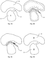
- a ROI is also schematically depicted in Fig. 2A .
- image gradients are calculated for each voxel.
- the largest gradients occur at the edges as illustrated by the arrows in fig. 2B .
- gradients of nearby voxels are compared along 13 cardinal, ordinal and 3D-diagonal directions.
- the neighboring voxels may be at different distances from the voxel that is under investigation.
- 4 cardinal and ordinal directions could be used in order to compare the directions of the gradients with regard to a pixel and its neighboring pixels.
- a function value F(p) can be calculated from the opposing gradients in different directions and with different step sizes dp.
- dp the number of steps in which the opposing gradient vectors are taken into account. All other gradient contributions are neglected.
- Different channel widths W i.e. where different channels which differ from each other in their general width or which vary, along their extension, in their widths, can preferably be addressed by a multi-resolution approach to calculate F(p) by calculating the maximal F(p) value over varying step sizes dp.
- the resolution is changed, according to the multi-resolution approach, in that the step sizes dp are changed.
- the voxels or pixels with a non-zero value F(p) define the channel 28, (or 18) between the two objects 22 and 24, or specifically for fig. 1 , the condyle head 12 and the fossa 14.
- a post-processing procedure can be applied in order to further improve the quality of the found channel in the CT or CBCT image data.
- This post-processing is particularly advantageous in view of the problem that particularly condylar joint bone can be very cancellous, i.e. showing great variation in density. The latter leads to gradients inside the bone volume which may then be identified as (apparent) channel voxels.
- the following post-processing steps may optionally be applied:
- All threshold parameters can be tuned to maximize the likelihood of segmentation and to have the least amount of loss of the surface object such as tissue, in particular bone.
- CT or CBCT images may exhibit so-called streak artifacts in the channel.
- These artifacts are pixels or voxels that indicate the presence of a surface object 16, 26, for example tissue, in particular bone, although there is no such bony object at the imaged position in reality.
- these streaks create holes in the volume (see fig. 2B ), making the surfaces 22 and 24 on each side to be erroneously connected.
- the closed channel volume 28 (see fig. 2C ) can be used to cut through the streak artifacts 26 and disconnect the objects 22 and 24 on each side.
- this can for example be done by resetting the gray values of the voxels or pixels in the closed channel volume to a) the background value or b) a value below the isovalue threshold used for surface reconstruction.
- Fig. 1C and 1C' illustrate an image of a temporomandibular joint reconstructed from CBCT image data, wherein the two bony structures were segregated by means of the preferred method described above.
- the condyle head 12 and the fossa 14 are not fused in the image.
- the surface 16 of Fig. 1A has been removed so that the mandible and skull are clearly separated.
- Fig. 1B shows the voxels that have been recognized as the channel 18 (with closed holes).
- Fig. 3A and 3A' show an image of a hip joint reconstructed from medical CT image data. More specifically, the femoral head 32 and acetabular fossa 34 are depicted. The surfaces of the femoral head and the fossa are fused in the image due to the surface reconstruction from the image data. Hence, we only have one object (marked by the number 1 in figure 3A' ).
- the connections 36 are typically reconstruction or streak artifacts.
- Fig. 3B depicts the channel 38 (defined by the hip joint) between the femoral head 32 and fossa 34 in the image of fig. 3A , as identified by our proposed method of locating the channel. Note that all holes in the channel volume were closed.
- Fig. 3C and 3C' show an image of the same hip joint reconstructed from the processed medical CT image data.
- the femoral head 32 and the fossa 34 are no longer fused in the image due to the additional segmentation of the two bony structures with the preferred method to locate the channel.
- we now have two separate objects as indicated by the numbers 2 and 3 inside the object drawings of figure 3C' ).
Landscapes
- Engineering & Computer Science (AREA)
- Computer Vision & Pattern Recognition (AREA)
- Physics & Mathematics (AREA)
- General Physics & Mathematics (AREA)
- Theoretical Computer Science (AREA)
- Apparatus For Radiation Diagnosis (AREA)
- Image Analysis (AREA)
- Magnetic Resonance Imaging Apparatus (AREA)
- Ultra Sonic Daignosis Equipment (AREA)
- Image Processing (AREA)
- Image Generation (AREA)
Claims (16)
- Computerimplementiertes Verfahren zum Identifizieren eines "Kanals" aus Bilddaten, die eine Vielzahl von Pixeln oder Voxeln umfassen, wobei es sich um einen Bildbereich zwischen mindestens zwei Objekten oder zwischen Abschnitten eines Objekts handelt, wobei die Objekte oder Abschnitte eines Objekts Verbindungen umfassen, die diesen Kanal schneiden, wobei das Verfahren einen Zyklus umfasst, der folgende Schritte umfasst:Berechnen von Bildgradienten der Pixel oder Voxel der Bilddaten, undAnalysieren der Ausrichtung der Bildgradienten,wobei, falls mindestens zwei der Bildgradienten in entgegengesetzte Richtungen voneinander weg deuten, die Pixel oder Voxel zwischen den entgegengesetzten Bildgradienten, die voneinander weg gerichtet sind, den Kanal ermitteln, wobei das Verfahren ferner Folgendes umfasst:Identifizieren der Pixel oder Voxel, die Löcher in dem Kanalbereich schaffen, wobei die Pixel oder Voxel die Objekte oder die Abschnitte eines Objekts auf jeder Seite des Kanals verbinden,Schließen des Kanalbereichs,Verwenden des geschlossenen Kanalbereichs, um die Verbindungen zu durchtrennen, wodurch die Objekte, oder die Abschnitte eines Objekts, getrennt werden und getrennte Objekte oder getrennte Abschnitte eines Objekts erhalten werden.
- Verfahren nach Anspruch 1, wobei die Objekte Objekte aus Gewebe sind, insbesondere Objekte aus Knochen des menschlichen oder tierischen Körpers.
- Verfahren nach einem der vorhergehenden Ansprüche, wobei ein Teil der Bilddaten derart ausgewählt ist, dass er Bilddaten von mindestens einem Abschnitt der mindestens zwei Objekte enthält.
- Verfahren nach einem der vorhergehenden Ansprüche, das ferner das Erzeugen von getrennten Flächen der zugehörigen getrennten Objekte umfasst, die durch den Kanal getrennt sind.
- Verfahren nach einem der vorhergehenden Ansprüche, wobei sich die Bildgradienten auf Unterschiede bei Farbwertintensitäten, insbesondere Grauwertintensitäten, Hounsfield-Skalawerten oder Hochfrequenzsignalstärkenwerten beziehen.
- Verfahren nach einem der vorhergehenden Ansprüche, wobei die mindestens zwei Objekte Abschnitte eines Gelenks sind, insbesondere eines Kiefergelenks, insbesondere eines Unterkiefers, insbesondere eines Unterkiefergelenkkopfs, und eines Schädels, insbesondere einer Schädelbasisgrube.
- Verfahren nach einem der vorhergehenden Ansprüche, wobei die Bilddaten Bilddaten aus Röntgenstrahlungs-, Computertomographie-, digitaler Volumentomographie-, Ultraschall- oder Magnetresonanzbildgebung umfassen.
- Verfahren nach einem der vorhergehenden Ansprüche, wobei sich die Bilddaten auf ein dreidimensionales Bild beziehen.
- Verfahren nach einem der vorhergehenden Ansprüche, wobei das Analysieren der Ausrichtung der Bildgradienten das Projizieren der Bildgradienten auf Einheitsvektoren umfasst, wobei die Einheitsvektoren bevorzugt in einer Himmelsrichtung, Nebenhimmelsrichtung und/oder einer dreidimensionalen diagonalen Richtung in Bezug auf das bestimmte Pixel oder Voxel definiert sind, das analysiert wird.
- Verfahren nach Anspruch 3 oder einem beliebigen von Anspruch 3 abhängigen Anspruch, wobei das Wählen des Teils der Bilddaten das Verwenden einer Korrelationstechnik umfasst.
- Verfahren nach einem der vorhergehenden Ansprüche, wobei die Bilddaten in einem Dateiformat bereitgestellt sind, das einem Standard für digitale Bildgebung und -kommunikation in der Medizin entspricht.
- Computerprogrammprodukt, das konfiguriert ist, um das Verfahren nach einem der vorhergehenden Ansprüche durchzuführen.
- Auslesbares Medium, das das Computerprogrammprodukt nach Anspruch 12 trägt.
- Vorrichtung, die dazu eingerichtet ist, das Computerprogrammprodukt nach Anspruch 12 durchzuführen.
- Medizinisches System, das dazu konfiguriert ist, das Verfahren nach einem der Ansprüche 1 bis 11 auszuführen.
- Medizinisches System nach Anspruch 15, das einen Computer, der dazu eingerichtet ist, das Computerprogrammprodukt nach Anspruch 12 durchzuführen, und eine Bildgebungsvorrichtung zum Erhalten von Bilddaten von mindestens zwei Flächenobjekten aus Knochen umfasst.
Applications Claiming Priority (2)
| Application Number | Priority Date | Filing Date | Title |
|---|---|---|---|
| EP15159963 | 2015-03-19 | ||
| PCT/EP2016/055756 WO2016146722A1 (en) | 2015-03-19 | 2016-03-17 | Segmentation of objects in image data using channel detection |
Publications (2)
| Publication Number | Publication Date |
|---|---|
| EP3271895A1 EP3271895A1 (de) | 2018-01-24 |
| EP3271895B1 true EP3271895B1 (de) | 2019-05-08 |
Family
ID=52780394
Family Applications (1)
| Application Number | Title | Priority Date | Filing Date |
|---|---|---|---|
| EP16713770.2A Active EP3271895B1 (de) | 2015-03-19 | 2016-03-17 | Segmentierung von objekten in bilddaten mittels kanalerkennung |
Country Status (8)
| Country | Link |
|---|---|
| US (1) | US10621726B2 (de) |
| EP (1) | EP3271895B1 (de) |
| JP (1) | JP6785237B2 (de) |
| CN (1) | CN107408301B (de) |
| BR (1) | BR112017019980B1 (de) |
| DK (1) | DK3271895T3 (de) |
| ES (1) | ES2738982T3 (de) |
| WO (1) | WO2016146722A1 (de) |
Families Citing this family (3)
| Publication number | Priority date | Publication date | Assignee | Title |
|---|---|---|---|---|
| JP6785237B2 (ja) | 2015-03-19 | 2020-11-18 | ノベル バイオケア サーヴィシィズ アーゲー | チャネル検出を使用する画像データ内の物体の分割 |
| ES2993048T3 (en) | 2018-12-20 | 2024-12-20 | Medicim Nv | Automated trimming of a surface mesh |
| CN114897750B (zh) * | 2022-04-02 | 2025-08-29 | 首都医科大学附属北京儿童医院 | 基于Sobel算子的腭中缝图像重构方法及系统 |
Family Cites Families (22)
| Publication number | Priority date | Publication date | Assignee | Title |
|---|---|---|---|---|
| FR2665597B1 (fr) * | 1990-07-31 | 1995-11-17 | Thomson Trt Defense | Procede et dispositif de localisation en temps reel de contours rectilignes dans une image numerisee, notamment pour la reconnaissance de formes dans un traitement d'analyse de scene. |
| BE1008128A3 (nl) | 1994-03-10 | 1996-01-23 | Materialise Nv | Werkwijze voor het ondersteunen van een voorwerp vervaardigd door stereolithografie of een andere snelle prototypevervaardigingswerkwijze en voor het vervaardigen van de daarbij gebruikte steunkonstruktie. |
| DE60136549D1 (de) * | 2000-09-14 | 2008-12-24 | Univ R | Verfahren zur manipulation medizinischer bilder |
| CA2427695C (en) * | 2001-04-26 | 2012-12-11 | Teijin Limited | Method for measuring 3d joint structure |
| EP2156350A1 (de) | 2007-05-25 | 2010-02-24 | Nobel Biocare Services AG | Verfahren und system für zahnmedizinische planung |
| CA2716598A1 (en) | 2008-03-04 | 2009-09-11 | Tomotherapy Incorporated | Method and system for improved image segmentation |
| ES2739460T3 (es) | 2008-03-19 | 2020-01-31 | Nobel Biocare Services Ag | Reposicionamiento de componentes relacionados con procedimientos quirúrgicos craneales en un paciente |
| EP2254068B1 (de) | 2009-05-18 | 2020-08-19 | Nobel Biocare Services AG | Verfahren und System, die einen verbesserten Datenabgleich zur virtuellen Planung bereitstellen |
| CN102598113A (zh) * | 2009-06-30 | 2012-07-18 | 安芯美特控股有限公司 | 匹配出现在两个或多个图像内的对象或人的方法、电路和系统 |
| EP2309450B1 (de) * | 2009-09-21 | 2016-04-06 | Orcamp AB | Verfahren zur Charakterisierung eines Blutgefäßes |
| US8457772B2 (en) | 2010-02-10 | 2013-06-04 | Biocad Medical, Inc. | Method for planning a dental component |
| JP4971525B2 (ja) | 2010-07-21 | 2012-07-11 | オリンパスメディカルシステムズ株式会社 | 画像処理装置及び画像処理装置の制御方法 |
| US8594820B2 (en) | 2010-09-17 | 2013-11-26 | Nobel Biocare Services Ag | Prosthesis manipulation in dental prosthesis design |
| WO2012096882A1 (en) * | 2011-01-11 | 2012-07-19 | Rutgers, The State University Of New Jersey | Method and apparatus for segmentation and registration of longitudinal images |
| CN102043957B (zh) * | 2011-01-11 | 2016-07-20 | 北京邮电大学 | 基于图像凹点的车辆分割方法 |
| EP2648160B1 (de) * | 2012-04-03 | 2017-03-08 | Intrasense | Die Topologie aufrechterhaltendes ROI-Remapping-Verfahren zwischen medizinischen Bildern |
| US9077943B2 (en) * | 2012-05-31 | 2015-07-07 | Apple Inc. | Local image statistics collection |
| TWI496112B (zh) * | 2013-09-13 | 2015-08-11 | Univ Nat Cheng Kung | 細胞影像分割方法以及核質比評估方法 |
| CN103942808B (zh) * | 2014-05-12 | 2017-05-10 | 福州大学 | 粘连岩石颗粒图像的分割方法 |
| US9218534B1 (en) * | 2014-11-17 | 2015-12-22 | Tandent Vision Science, Inc. | Method and system for classifying painted road markings in an automotive driver-vehicle-assistance device |
| JP6785237B2 (ja) | 2015-03-19 | 2020-11-18 | ノベル バイオケア サーヴィシィズ アーゲー | チャネル検出を使用する画像データ内の物体の分割 |
| KR102419552B1 (ko) | 2016-06-21 | 2022-07-11 | 노벨 바이오케어 서비시스 아게 | 치아 수복물의 형상, 위치 및 배향 중 적어도 하나를 추정하는 방법 |
-
2016
- 2016-03-17 JP JP2017543982A patent/JP6785237B2/ja active Active
- 2016-03-17 US US15/559,364 patent/US10621726B2/en active Active
- 2016-03-17 WO PCT/EP2016/055756 patent/WO2016146722A1/en not_active Ceased
- 2016-03-17 CN CN201680015818.8A patent/CN107408301B/zh active Active
- 2016-03-17 EP EP16713770.2A patent/EP3271895B1/de active Active
- 2016-03-17 ES ES16713770T patent/ES2738982T3/es active Active
- 2016-03-17 BR BR112017019980-7A patent/BR112017019980B1/pt active IP Right Grant
- 2016-03-17 DK DK16713770.2T patent/DK3271895T3/da active
Non-Patent Citations (1)
| Title |
|---|
| None * |
Also Published As
| Publication number | Publication date |
|---|---|
| JP6785237B2 (ja) | 2020-11-18 |
| CN107408301B (zh) | 2021-07-06 |
| WO2016146722A1 (en) | 2016-09-22 |
| BR112017019980B1 (pt) | 2024-03-12 |
| ES2738982T3 (es) | 2020-01-28 |
| US20180075606A1 (en) | 2018-03-15 |
| US10621726B2 (en) | 2020-04-14 |
| BR112017019980A2 (pt) | 2018-06-19 |
| EP3271895A1 (de) | 2018-01-24 |
| CN107408301A (zh) | 2017-11-28 |
| DK3271895T3 (da) | 2019-08-05 |
| JP2018512188A (ja) | 2018-05-17 |
Similar Documents
| Publication | Publication Date | Title |
|---|---|---|
| Klinder et al. | Automated model-based vertebra detection, identification, and segmentation in CT images | |
| US10937250B2 (en) | Methods of reconstructing skulls | |
| US10083515B2 (en) | Method and system for segmenting medical imaging data according to a skeletal atlas | |
| AU2011266777B2 (en) | Method and system of automatic determination of geometric elements from a 3D medical image of a bone | |
| JP5932879B2 (ja) | 患者特有の骨殻の3dモデルを生成する方法 | |
| JP7463510B2 (ja) | 骨断片化のケースにおける整形外科手術のための術前計画及び術中ガイダンス | |
| EP2486541B1 (de) | Bilddatenverarbeitung | |
| Wang et al. | Validation of bone segmentation and improved 3-D registration using contour coherency in CT data | |
| US20130089253A1 (en) | Method for determining bone resection on a deformed bone surface from few parameters | |
| Hosseinian et al. | 3D Reconstruction from Multi-View Medical X-ray images–review and evaluation of existing methods | |
| Klinder et al. | Automated model-based rib cage segmentation and labeling in CT images | |
| CN113870098A (zh) | 一种基于脊柱分层重建的Cobb角自动测量方法 | |
| CN106846346A (zh) | 基于关键帧标记的序列ct图像骨盆轮廓快速提取方法 | |
| KR20150047885A (ko) | 3차원 무릎 관절 영상 생성 방법 및 장치 | |
| US10621726B2 (en) | Segmentation of objects in image data using channel detection | |
| De Raedt et al. | Automated measurement of diagnostic angles for hip dysplasia | |
| Cresson et al. | Coupling 2D/3D registration method and statistical model to perform 3D reconstruction from partial x-rays images data | |
| Ramakrishnan et al. | Automatic three-dimensional rib centerline extraction from CT scans for enhanced visualization and anatomical context | |
| CN120107701B (zh) | 一种骨折类型识别及复位路径规划方法 | |
| Tan et al. | Acetabular rim and surface segmentation for hip surgery planning and dysplasia evaluation | |
| Vandemeulebroucke et al. | Automated estimation of hip prosthesis migration: a feasibility study | |
| Liu et al. | Model-based 3D segmentation of the bones of joints in medical images | |
| Wirth et al. | An algorithm for extracting the skin surface in MR breast images | |
| El Dakhakhni | Reconstruction of Patient-Specific Bone Models from X-Ray Radiography | |
| El Sheikh et al. | Construction of point cloud by slice-adaptive thresholding of computer tomography (CT) images at the human knee joint |
Legal Events
| Date | Code | Title | Description |
|---|---|---|---|
| STAA | Information on the status of an ep patent application or granted ep patent |
Free format text: STATUS: THE INTERNATIONAL PUBLICATION HAS BEEN MADE |
|
| PUAI | Public reference made under article 153(3) epc to a published international application that has entered the european phase |
Free format text: ORIGINAL CODE: 0009012 |
|
| STAA | Information on the status of an ep patent application or granted ep patent |
Free format text: STATUS: REQUEST FOR EXAMINATION WAS MADE |
|
| 17P | Request for examination filed |
Effective date: 20171019 |
|
| AK | Designated contracting states |
Kind code of ref document: A1 Designated state(s): AL AT BE BG CH CY CZ DE DK EE ES FI FR GB GR HR HU IE IS IT LI LT LU LV MC MK MT NL NO PL PT RO RS SE SI SK SM TR |
|
| AX | Request for extension of the european patent |
Extension state: BA ME |
|
| DAV | Request for validation of the european patent (deleted) | ||
| DAX | Request for extension of the european patent (deleted) | ||
| GRAP | Despatch of communication of intention to grant a patent |
Free format text: ORIGINAL CODE: EPIDOSNIGR1 |
|
| STAA | Information on the status of an ep patent application or granted ep patent |
Free format text: STATUS: GRANT OF PATENT IS INTENDED |
|
| INTG | Intention to grant announced |
Effective date: 20181002 |
|
| GRAS | Grant fee paid |
Free format text: ORIGINAL CODE: EPIDOSNIGR3 |
|
| GRAA | (expected) grant |
Free format text: ORIGINAL CODE: 0009210 |
|
| STAA | Information on the status of an ep patent application or granted ep patent |
Free format text: STATUS: THE PATENT HAS BEEN GRANTED |
|
| AK | Designated contracting states |
Kind code of ref document: B1 Designated state(s): AL AT BE BG CH CY CZ DE DK EE ES FI FR GB GR HR HU IE IS IT LI LT LU LV MC MK MT NL NO PL PT RO RS SE SI SK SM TR |
|
| REG | Reference to a national code |
Ref country code: GB Ref legal event code: FG4D |
|
| REG | Reference to a national code |
Ref country code: CH Ref legal event code: EP Ref country code: AT Ref legal event code: REF Ref document number: 1131380 Country of ref document: AT Kind code of ref document: T Effective date: 20190515 |
|
| REG | Reference to a national code |
Ref country code: DE Ref legal event code: R096 Ref document number: 602016013632 Country of ref document: DE Ref country code: IE Ref legal event code: FG4D |
|
| REG | Reference to a national code |
Ref country code: DK Ref legal event code: T3 Effective date: 20190801 |
|
| REG | Reference to a national code |
Ref country code: SE Ref legal event code: TRGR |
|
| REG | Reference to a national code |
Ref country code: NL Ref legal event code: MP Effective date: 20190508 |
|
| REG | Reference to a national code |
Ref country code: LT Ref legal event code: MG4D |
|
| PG25 | Lapsed in a contracting state [announced via postgrant information from national office to epo] |
Ref country code: NO Free format text: LAPSE BECAUSE OF FAILURE TO SUBMIT A TRANSLATION OF THE DESCRIPTION OR TO PAY THE FEE WITHIN THE PRESCRIBED TIME-LIMIT Effective date: 20190808 Ref country code: LT Free format text: LAPSE BECAUSE OF FAILURE TO SUBMIT A TRANSLATION OF THE DESCRIPTION OR TO PAY THE FEE WITHIN THE PRESCRIBED TIME-LIMIT Effective date: 20190508 Ref country code: FI Free format text: LAPSE BECAUSE OF FAILURE TO SUBMIT A TRANSLATION OF THE DESCRIPTION OR TO PAY THE FEE WITHIN THE PRESCRIBED TIME-LIMIT Effective date: 20190508 Ref country code: HR Free format text: LAPSE BECAUSE OF FAILURE TO SUBMIT A TRANSLATION OF THE DESCRIPTION OR TO PAY THE FEE WITHIN THE PRESCRIBED TIME-LIMIT Effective date: 20190508 Ref country code: PT Free format text: LAPSE BECAUSE OF FAILURE TO SUBMIT A TRANSLATION OF THE DESCRIPTION OR TO PAY THE FEE WITHIN THE PRESCRIBED TIME-LIMIT Effective date: 20190908 Ref country code: AL Free format text: LAPSE BECAUSE OF FAILURE TO SUBMIT A TRANSLATION OF THE DESCRIPTION OR TO PAY THE FEE WITHIN THE PRESCRIBED TIME-LIMIT Effective date: 20190508 Ref country code: NL Free format text: LAPSE BECAUSE OF FAILURE TO SUBMIT A TRANSLATION OF THE DESCRIPTION OR TO PAY THE FEE WITHIN THE PRESCRIBED TIME-LIMIT Effective date: 20190508 |
|
| PG25 | Lapsed in a contracting state [announced via postgrant information from national office to epo] |
Ref country code: BG Free format text: LAPSE BECAUSE OF FAILURE TO SUBMIT A TRANSLATION OF THE DESCRIPTION OR TO PAY THE FEE WITHIN THE PRESCRIBED TIME-LIMIT Effective date: 20190808 Ref country code: LV Free format text: LAPSE BECAUSE OF FAILURE TO SUBMIT A TRANSLATION OF THE DESCRIPTION OR TO PAY THE FEE WITHIN THE PRESCRIBED TIME-LIMIT Effective date: 20190508 Ref country code: RS Free format text: LAPSE BECAUSE OF FAILURE TO SUBMIT A TRANSLATION OF THE DESCRIPTION OR TO PAY THE FEE WITHIN THE PRESCRIBED TIME-LIMIT Effective date: 20190508 Ref country code: GR Free format text: LAPSE BECAUSE OF FAILURE TO SUBMIT A TRANSLATION OF THE DESCRIPTION OR TO PAY THE FEE WITHIN THE PRESCRIBED TIME-LIMIT Effective date: 20190809 |
|
| REG | Reference to a national code |
Ref country code: AT Ref legal event code: MK05 Ref document number: 1131380 Country of ref document: AT Kind code of ref document: T Effective date: 20190508 |
|
| REG | Reference to a national code |
Ref country code: ES Ref legal event code: FG2A Ref document number: 2738982 Country of ref document: ES Kind code of ref document: T3 Effective date: 20200128 |
|
| PG25 | Lapsed in a contracting state [announced via postgrant information from national office to epo] |
Ref country code: SK Free format text: LAPSE BECAUSE OF FAILURE TO SUBMIT A TRANSLATION OF THE DESCRIPTION OR TO PAY THE FEE WITHIN THE PRESCRIBED TIME-LIMIT Effective date: 20190508 Ref country code: AT Free format text: LAPSE BECAUSE OF FAILURE TO SUBMIT A TRANSLATION OF THE DESCRIPTION OR TO PAY THE FEE WITHIN THE PRESCRIBED TIME-LIMIT Effective date: 20190508 Ref country code: EE Free format text: LAPSE BECAUSE OF FAILURE TO SUBMIT A TRANSLATION OF THE DESCRIPTION OR TO PAY THE FEE WITHIN THE PRESCRIBED TIME-LIMIT Effective date: 20190508 Ref country code: CZ Free format text: LAPSE BECAUSE OF FAILURE TO SUBMIT A TRANSLATION OF THE DESCRIPTION OR TO PAY THE FEE WITHIN THE PRESCRIBED TIME-LIMIT Effective date: 20190508 Ref country code: RO Free format text: LAPSE BECAUSE OF FAILURE TO SUBMIT A TRANSLATION OF THE DESCRIPTION OR TO PAY THE FEE WITHIN THE PRESCRIBED TIME-LIMIT Effective date: 20190508 |
|
| REG | Reference to a national code |
Ref country code: DE Ref legal event code: R097 Ref document number: 602016013632 Country of ref document: DE |
|
| PG25 | Lapsed in a contracting state [announced via postgrant information from national office to epo] |
Ref country code: SM Free format text: LAPSE BECAUSE OF FAILURE TO SUBMIT A TRANSLATION OF THE DESCRIPTION OR TO PAY THE FEE WITHIN THE PRESCRIBED TIME-LIMIT Effective date: 20190508 |
|
| PLBE | No opposition filed within time limit |
Free format text: ORIGINAL CODE: 0009261 |
|
| STAA | Information on the status of an ep patent application or granted ep patent |
Free format text: STATUS: NO OPPOSITION FILED WITHIN TIME LIMIT |
|
| PG25 | Lapsed in a contracting state [announced via postgrant information from national office to epo] |
Ref country code: TR Free format text: LAPSE BECAUSE OF FAILURE TO SUBMIT A TRANSLATION OF THE DESCRIPTION OR TO PAY THE FEE WITHIN THE PRESCRIBED TIME-LIMIT Effective date: 20190508 |
|
| 26N | No opposition filed |
Effective date: 20200211 |
|
| PG25 | Lapsed in a contracting state [announced via postgrant information from national office to epo] |
Ref country code: PL Free format text: LAPSE BECAUSE OF FAILURE TO SUBMIT A TRANSLATION OF THE DESCRIPTION OR TO PAY THE FEE WITHIN THE PRESCRIBED TIME-LIMIT Effective date: 20190508 |
|
| PG25 | Lapsed in a contracting state [announced via postgrant information from national office to epo] |
Ref country code: SI Free format text: LAPSE BECAUSE OF FAILURE TO SUBMIT A TRANSLATION OF THE DESCRIPTION OR TO PAY THE FEE WITHIN THE PRESCRIBED TIME-LIMIT Effective date: 20190508 |
|
| PG25 | Lapsed in a contracting state [announced via postgrant information from national office to epo] |
Ref country code: MC Free format text: LAPSE BECAUSE OF FAILURE TO SUBMIT A TRANSLATION OF THE DESCRIPTION OR TO PAY THE FEE WITHIN THE PRESCRIBED TIME-LIMIT Effective date: 20190508 |
|
| PG25 | Lapsed in a contracting state [announced via postgrant information from national office to epo] |
Ref country code: LU Free format text: LAPSE BECAUSE OF NON-PAYMENT OF DUE FEES Effective date: 20200317 |
|
| PG25 | Lapsed in a contracting state [announced via postgrant information from national office to epo] |
Ref country code: IE Free format text: LAPSE BECAUSE OF NON-PAYMENT OF DUE FEES Effective date: 20200317 |
|
| PG25 | Lapsed in a contracting state [announced via postgrant information from national office to epo] |
Ref country code: MT Free format text: LAPSE BECAUSE OF FAILURE TO SUBMIT A TRANSLATION OF THE DESCRIPTION OR TO PAY THE FEE WITHIN THE PRESCRIBED TIME-LIMIT Effective date: 20190508 Ref country code: CY Free format text: LAPSE BECAUSE OF FAILURE TO SUBMIT A TRANSLATION OF THE DESCRIPTION OR TO PAY THE FEE WITHIN THE PRESCRIBED TIME-LIMIT Effective date: 20190508 |
|
| PG25 | Lapsed in a contracting state [announced via postgrant information from national office to epo] |
Ref country code: MK Free format text: LAPSE BECAUSE OF FAILURE TO SUBMIT A TRANSLATION OF THE DESCRIPTION OR TO PAY THE FEE WITHIN THE PRESCRIBED TIME-LIMIT Effective date: 20190508 Ref country code: IS Free format text: LAPSE BECAUSE OF FAILURE TO SUBMIT A TRANSLATION OF THE DESCRIPTION OR TO PAY THE FEE WITHIN THE PRESCRIBED TIME-LIMIT Effective date: 20190908 |
|
| P01 | Opt-out of the competence of the unified patent court (upc) registered |
Effective date: 20230515 |
|
| PGFP | Annual fee paid to national office [announced via postgrant information from national office to epo] |
Ref country code: ES Payment date: 20250414 Year of fee payment: 10 |
|
| PGFP | Annual fee paid to national office [announced via postgrant information from national office to epo] |
Ref country code: CH Payment date: 20250401 Year of fee payment: 10 |
|
| PGFP | Annual fee paid to national office [announced via postgrant information from national office to epo] |
Ref country code: FR Payment date: 20251231 Year of fee payment: 11 |
|
| REG | Reference to a national code |
Ref country code: CH Ref legal event code: U11 Free format text: ST27 STATUS EVENT CODE: U-0-0-U10-U11 (AS PROVIDED BY THE NATIONAL OFFICE) Effective date: 20260401 |
|
| PGFP | Annual fee paid to national office [announced via postgrant information from national office to epo] |
Ref country code: SE Payment date: 20260105 Year of fee payment: 11 |
|
| PGFP | Annual fee paid to national office [announced via postgrant information from national office to epo] |
Ref country code: GB Payment date: 20260106 Year of fee payment: 11 |
|
| PGFP | Annual fee paid to national office [announced via postgrant information from national office to epo] |
Ref country code: DE Payment date: 20260102 Year of fee payment: 11 Ref country code: DK Payment date: 20260313 Year of fee payment: 11 |
|
| PGFP | Annual fee paid to national office [announced via postgrant information from national office to epo] |
Ref country code: BE Payment date: 20260105 Year of fee payment: 11 Ref country code: IT Payment date: 20260220 Year of fee payment: 11 |