EP3271199B1 - Cabin pressurization system for agricultural machines with filtration system - Google Patents
Cabin pressurization system for agricultural machines with filtration system Download PDFInfo
- Publication number
- EP3271199B1 EP3271199B1 EP16714008.6A EP16714008A EP3271199B1 EP 3271199 B1 EP3271199 B1 EP 3271199B1 EP 16714008 A EP16714008 A EP 16714008A EP 3271199 B1 EP3271199 B1 EP 3271199B1
- Authority
- EP
- European Patent Office
- Prior art keywords
- air inlet
- box
- external air
- hvac system
- cabin
- Prior art date
- Legal status (The legal status is an assumption and is not a legal conclusion. Google has not performed a legal analysis and makes no representation as to the accuracy of the status listed.)
- Active
Links
Images

Classifications
-
- B—PERFORMING OPERATIONS; TRANSPORTING
- B60—VEHICLES IN GENERAL
- B60H—ARRANGEMENTS OF HEATING, COOLING, VENTILATING OR OTHER AIR-TREATING DEVICES SPECIALLY ADAPTED FOR PASSENGER OR GOODS SPACES OF VEHICLES
- B60H1/00—Heating, cooling or ventilating [HVAC] devices
- B60H1/00357—Air-conditioning arrangements specially adapted for particular vehicles
- B60H1/00378—Air-conditioning arrangements specially adapted for particular vehicles for tractor or load vehicle cabins
-
- B—PERFORMING OPERATIONS; TRANSPORTING
- B60—VEHICLES IN GENERAL
- B60H—ARRANGEMENTS OF HEATING, COOLING, VENTILATING OR OTHER AIR-TREATING DEVICES SPECIALLY ADAPTED FOR PASSENGER OR GOODS SPACES OF VEHICLES
- B60H3/00—Other air-treating devices
- B60H3/06—Filtering
- B60H3/0608—Filter arrangements in the air stream
- B60H3/0633—Filter arrangements in the air stream with provisions for regenerating or cleaning the filter element
-
- B—PERFORMING OPERATIONS; TRANSPORTING
- B60—VEHICLES IN GENERAL
- B60H—ARRANGEMENTS OF HEATING, COOLING, VENTILATING OR OTHER AIR-TREATING DEVICES SPECIALLY ADAPTED FOR PASSENGER OR GOODS SPACES OF VEHICLES
- B60H3/00—Other air-treating devices
- B60H3/06—Filtering
- B60H2003/0683—Filtering the quality of the filter or the air being checked
Definitions
- the present invention relates to a cabin air treatment apparatus for an agricultural machine, comprising at least an external air inlet, a filtration system connected downstream of the external air inlet, an HVAC system connected downstream of the filtration system, and a cabin air supply outlet connected downstream of the HVAC system, as well as a condensation system comprising a condenser connected to an evaporator of the HVAC system, and a fan associated to the condenser.
- a cabin air treatment apparatus according to the preamble of claim 1 is disclosed in US4467706 .
- Conventional air treatment apparatus for agricultural machines provide dust filtration, but aerosols and vapours can, in practice, still flow freely into the vehicle cabin.
- the invention therefore proposes an apparatus of the type defined initially, further comprising a hermetically closed box inside which the HVAC system is housed, said box having a levelling opening for placing the box into communication with a cabin of the agricultural machine to level a pressure inside the box with a pressure inside the cabin,
- the HVAC system is therefore housed within a pressurized box, at the same pressure as that present within the cabin.
- the pressurization in the environment of the box surrounding the treatment apparatus prevents external contaminants from coming into contact with the various components of the HVAC system and with the fan. Consequently, it is unnecessary to have every individual component made so as to be protected from contaminant penetration; only the parts of the box communicating with the outside, particularly the air inlets with their filters, have to be configured for this purpose. This obviously provides a high degree of simplification as regards construction, resulting in cost savings, as well as greater safety in terms of operator protection.
- By means of the cleaning duct and the fan of the condensation system it is possible to carry out a cleaning operation on the filter, by means of which contaminants possibly present downstream of the filter are discharged directly to the outside, preventing them from reaching the HVAC system and from there the cabin.
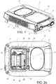
- Figures 1 and 2a show a roof R of an agricultural machine, while the letter C indicates an area to be occupied by the cabin of the agricultural machine, under the roof R.
- the cabin is required to be isolated from the external environment (at least in the higher safety classes).
- a box 1, hermetically closed by a cover 2, is placed on the roof R of the agricultural machine.
- Figure 2a shows the roof R with the box 1 from which the cover 2 has been removed; in particular, a gasket placed along a perimetric edge of the box is visible.
- the box 1 forms a compartment 3, in which a part of an air treatment apparatus 10 according to the invention is placed.
- Figures 1 and 2a further show a second cover 2' which covers a second compartment 3' (visible in Figures 6 to 9 ), inside of which another part of the air treatment apparatus is arranged.
- the air treatment apparatus essentially comprises a first and a possible second external air inlet 11, 16, formed through the walls of the box 1, through which inlets air is drawn from the external environment, a filtration system 20 connected downstream of the external air inlets 11, 16, an HVAC system 30 connected downstream of the filtration system 20, and a cabin air supply outlet 40 connected downstream of the HVAC system 30 (visible in Figure 3 ), through which treated air is supplied to the cabin C at a pressure greater than the pressure of the external environment.
- the air treatment apparatus further comprises a condensation system 70 arranged inside the second compartment 3'.
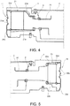
- the filtration system 20 comprises a filter 21 for effecting a filtration of at least one among dust, aerosols and vapours, arranged at the first air inlet 11, and an air inlet duct 23 being arranged directly connected downstream of the filter 21 and inside the box 1, and connecting the filter 21 to the HVAC system 30.
- An equivalent hole (not shown) is conventionally provided inside the cabin to adjust the pressurization of the environment inside the cabin.
- the filter 21 comprises a filter box 21a and a filter body 21b housed inside the filter box 21a.
- the filter body 21b is a filter chosen from among known filters capable of suppressing dust, aerosols and vapours, in other words a filter of category 4 according to European Standard EN 15695.
- An air inlet grille 21c is also mounted at the interface between the first air inlet 11 and the external environment, upstream of the filter body 21b. Sealing means 21d are interposed between the air inlet grille 21c and the air inlet of the filter box 21a.
- a shutter device 21e is placed at the air inlet grille 21c, this device being of the type biased towards a closed position and openable by a pressure downstream of the shutter device 21e lower than the pressure of the external environment.
- the shutter device 21e consists of a plurality of fins of elastic material, which bend towards the inside of the box 1, thereby opening the first air inlet 11, when the pressure downstream of the fins is lower than the pressure of the external environment.
- the filter box 21a is fixed to the box 1, and its outlet is connected to the air inlet duct 23.
- the duct 23 is provided with an air distribution valve 24, shown schematically in Figures 6 to 10 , whereby the first air inlet 11 is in selectively enabled or disabled communication with the HVAC system 30, as explained subsequently.
- the air inlet 11 is further connected to a cleaning duct 25 connected to a fan of the condensation system 70 and provided for cleaning the filter 21, as will be explained subsequently.
- the valve 24 is configured to close/open the inlet to the HVAC system 25 and at the same time open/close the inlet to the fan of the condensation system 70.
- the filtration system 20 can further comprise a second filter 26 for effecting a mechanical filtration of the dust, placed at the second air inlet 16.
- the second filter 26 comprises a filter box 26a and a filter body 26b housed inside the filter box 26a.
- the filter body 26b is a filter of category 2 according to European Standard EN 15695, and is therefore of a lower category than the first filter 21.
- An air inlet grille 26c is also mounted at the interface between the second air inlet 16 and the external environment, upstream of the filter body 26b. Sealing means 26d are interposed between the air inlet grille 26c and the air inlet of the filter box 26a.
- a shutter device 26e is placed at the air inlet grille 26c, this device being of the type biased towards a closed position and openable by a pressure downstream of the shutter device 26e lower than the pressure of the external environment.
- the shutter device 26e consists of a plurality of fins of elastic material, which bend towards the inside of the box 1, thereby opening the second air inlet 16, when the pressure downstream of the fins is lower than the pressure of the external environment.
- the filter box 26a is fixed to the box 1, and its air outlet is connected in a sealed way to a passage formed through a wall of the box 1, which, at its inner end, is connected in a sealed way via a duct 27 to the inlet of the HVAC system 30.
- the duct 27 is provided with an air distribution valve 28, shown schematically in Figures 6 to 10 , whereby the first air inlet 16 is in selectively enabled or disabled communication with the HVAC system 30, as explained subsequently.
- the external air inlet 16 is also connected through the duct 27 and the air distribution valve 28 to the internal environment of the box 1 in order to keep the second filter 26 under pressure, as explained subsequently.
- the HVAC system 30 is of a conventional type; fresh and recycled air to be supplied to the cabin C is dehumidified and brought to the desired temperature by means of this system.
- the HVAC system 30 may comprise an air mixing plenum 31, one or more fans 32 (visible in Figures 6 to 10 ), an evaporator 33, and a heater 34.
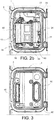
- the cabin C is also connected to the air mixing plenum 31 of the HVAC system 30 through an air recycling opening 50 formed on the box 1, visible in Figure 3 .
- the box 1 also has a levelling opening 60, visible in Figure 3 , for placing the internal space 3 of the box 1 into communication with the cabin C to level the pressure inside the box 1 with the pressure inside the cabin C.
- the condensation system 70 arranged inside the second compartment 3' of the roof R, conventionally comprises one or more condensers 71 and one or more fans 73 associated to the condensers 71.
- the condenser(s) 71 is/are conventionally connected to the evaporator(s) 33 of the HVAC system 30, within a cooling fluid circuit, and the fan(s) 73 serve to cool/condense the cooling fluid within the condenser(s) 71.
- the cleaning duct 25 is connected to an air inlet of the fan(s) 73.
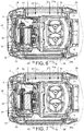
- Figure 6 shows a cleaning configuration, which may be adopted when the apparatus is started up.
- the distribution valve 24 associated with the duct 23 connecting the first external air inlet 11 to the HVAC system 30 is positioned so as to disable the communication between the first external air inlet 11 and the HVAC system 30, and to enable the communication between the first external air inlet 11 and the cleaning duct 25.
- the distribution valve 28 associated with the duct 27 connecting the second external air inlet 16 to the HVAC system 30 is positioned so as to disable the communication between the second external air inlet 16 and the HVAC system 30.
- the unnumbered arrows depicted in Figure 6 represent the air path created by this configuration.
- the air entering from the air inlet 11, having been drawn in by the fan 73 of the condensation system 70 is used to remove any deposits within the first filter 21 and to discharge them to the outside through an air outlet of the condensation system 70.
- Figure 7 shows a configuration of initial pressurization of the apparatus.
- the distribution valve 24 associated with the duct 23 connecting the first external air inlet 11 to the HVAC system 30 is positioned so as to enable the communication between the first external air inlet 11 and the HVAC system 30, and to disable the communication between the first external air inlet 11 and the cleaning duct 25.
- the distribution valve 28 associated with the duct 27 connecting the second external air inlet 16 to the HVAC system 30 remains in the position which prevents communication between the second external air inlet 16 and the HVAC system 30.
- the unnumbered arrows depicted in Figure 7 represent the air path created by this configuration.
- the air entering from the air inlet 11, having been drawn in by the fan 32 of the HVAC system 30, passes through the first filter 21 and the HVAC system 30, and then through the cabin air supply outlet 40 to pressurize the cabin C.
- Figure 8 shows a configuration of steady-state pressurization of the apparatus.
- the distribution valve 24 associated with the duct 23 connecting the first external air inlet 11 to the HVAC system 30 remains in the position which allows communication between the first external air inlet 16 and the HVAC system 30, and the distribution valve 28 associated with the duct 27 connecting the second external air inlet 16 to the HVAC system 30 remains in the position which prevents communication between the second external air inlet 16 and the HVAC system 30.
- This position of the distribution valve 28 also allows communication between the second external air inlet 16 and the internal space 3 of the box 1.
- the unnumbered arrows depicted in Figure 8 represent the path of the air.
- the air which continues to enter the cabin C along the path indicated above with reference to Figure 7 also passes from the cabin C into the space 3 within the box 1, through the levelling opening 60, so that it also pressurizes the interior of the box 1, and passes from the space 3 into the duct 27 in communication with the space 3, so that it also pressurizes the second filter 26.
- Figure 9 shows a configuration of anomaly detection in the apparatus.
- the distribution valve 24 associated with the duct 23 connecting the first external air inlet 11 to the HVAC system 30 is positioned so as to disable the communication between the first external air inlet 11 and the HVAC system 30, and the distribution valve 28 associated with the duct 27 connecting the second external air inlet 16 to the HVAC system 30 is positioned so as to disable the communication between the second external air inlet 16 and the HVAC system 30. In this way, external air is prevented from entering the cabin C through the two external air inlets 11, 16.
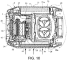
- Figure 10 shows an operating configuration with the lower category filter associated with the second external air inlet.
- This configuration may be used as an alternative to the higher category operating configuration (shown in the preceding figures) when the operating conditions do not require a high degree of protection against contaminants.
- the distribution valve 24 associated with the duct 23 connecting the first external air inlet 11 to the HVAC system 30 is positioned so as to disable the communication between the first external air inlet 11 and the HVAC system 30, and the distribution valve 28 associated with the duct 27 connecting the second external air inlet 16 to the HVAC system 30 is positioned so as to enable the communication between the second external air inlet 16 and the HVAC system 30.
- the unnumbered arrows depicted in Figure 10 represent the air path created by this configuration.
- the air which continues to enter the cabin C also passes from the cabin C into the space 3 within the box 1, through the levelling opening 60, so that it also pressurizes the interior of the box 1.
Description
- The present invention relates to a cabin air treatment apparatus for an agricultural machine, comprising at least an external air inlet, a filtration system connected downstream of the external air inlet, an HVAC system connected downstream of the filtration system, and a cabin air supply outlet connected downstream of the HVAC system, as well as a condensation system comprising a condenser connected to an evaporator of the HVAC system, and a fan associated to the condenser. A cabin air treatment apparatus according to the preamble of
claim 1 is disclosed inUS4467706 . Conventional air treatment apparatus for agricultural machines provide dust filtration, but aerosols and vapours can, in practice, still flow freely into the vehicle cabin. As a general rule, these known apparatus are inflexible, and it is difficult to use them to achieve satisfactory levels of pressurization in the cab, in particular if the latest standards are borne in mind. There is also the problem of isolating the treatment apparatus to avoid penetration by contaminants, which requires accurate design of the sealing elements of the individual components of the apparatus.
The invention therefore proposes an apparatus of the type defined initially, further comprising a hermetically closed box inside which the HVAC system is housed, said box having a levelling opening for placing the box into communication with a cabin of the agricultural machine to level a pressure inside the box with a pressure inside the cabin, - wherein said at least one external air inlet comprises an external air inlet formed on the box,
- wherein the condensation system is arranged outside of said box, and
- wherein the filtration system comprises:
- a filter for effecting a filtration of at least one among dust, aerosols and vapours, arranged at the external air inlet, and
- an air inlet duct arranged directly connected downstream of the filter and provided with selecting valve means having a first outlet connected to the HVAC system, and a second outlet connected to the fan of the condensation system, through a cleaning duct.
- According to the invention, the HVAC system is therefore housed within a pressurized box, at the same pressure as that present within the cabin. The pressurization in the environment of the box surrounding the treatment apparatus prevents external contaminants from coming into contact with the various components of the HVAC system and with the fan. Consequently, it is unnecessary to have every individual component made so as to be protected from contaminant penetration; only the parts of the box communicating with the outside, particularly the air inlets with their filters, have to be configured for this purpose. This obviously provides a high degree of simplification as regards construction, resulting in cost savings, as well as greater safety in terms of operator protection. By means of the cleaning duct and the fan of the condensation system, it is possible to carry out a cleaning operation on the filter, by means of which contaminants possibly present downstream of the filter are discharged directly to the outside, preventing them from reaching the HVAC system and from there the cabin.
- Preferred embodiments of the invention are defined in the dependent claims, which are to be considered as an integral part of the present description.
- Further characteristics and advantages of the apparatus according to the invention will be made clearer by the following detailed description of an embodiment of the invention, given with reference to the attached drawings which are provided purely as non-limiting illustrations, in which:
-
Figure 1 is a perspective view of a roof of an agricultural machine provided with a treatment apparatus according to the invention; -
Figure 2a is a plan view of the roof ofFigure 1 , with the cover removed; -
Figure 2b is an enlarged plan view of a part of the roof with the cover removed; -
Figure 3 is a plan view of the part shown inFigure 2 , with the treatment apparatus also removed; -
Figure 4 is a sectional view of a first external air inlet of the treatment apparatus; -
Figure 5 is a sectional view of a second external air inlet of the treatment apparatus; -
Figures 6 to 10 are sectional views of the roof, showing different operating configurations of the treatment apparatus. -
Figures 1 and 2a show a roof R of an agricultural machine, while the letter C indicates an area to be occupied by the cabin of the agricultural machine, under the roof R. According to the regulations on exposure to hazardous substances, the cabin is required to be isolated from the external environment (at least in the higher safety classes). - A
box 1, hermetically closed by acover 2, is placed on the roof R of the agricultural machine.Figure 2a shows the roof R with thebox 1 from which thecover 2 has been removed; in particular, a gasket placed along a perimetric edge of the box is visible. As can also be seen inFigure 2b , thebox 1 forms acompartment 3, in which a part of anair treatment apparatus 10 according to the invention is placed.Figures 1 and 2a further show a second cover 2' which covers a second compartment 3' (visible inFigures 6 to 9 ), inside of which another part of the air treatment apparatus is arranged. - The air treatment apparatus essentially comprises a first and a possible second
external air inlet box 1, through which inlets air is drawn from the external environment, afiltration system 20 connected downstream of theexternal air inlets HVAC system 30 connected downstream of thefiltration system 20, and a cabinair supply outlet 40 connected downstream of the HVAC system 30 (visible inFigure 3 ), through which treated air is supplied to the cabin C at a pressure greater than the pressure of the external environment. The air treatment apparatus further comprises acondensation system 70 arranged inside the second compartment 3'. - With reference to
Figures 4 and6 , thefiltration system 20 comprises afilter 21 for effecting a filtration of at least one among dust, aerosols and vapours, arranged at thefirst air inlet 11, and anair inlet duct 23 being arranged directly connected downstream of thefilter 21 and inside thebox 1, and connecting thefilter 21 to theHVAC system 30. - An equivalent hole (not shown) is conventionally provided inside the cabin to adjust the pressurization of the environment inside the cabin.
- With reference to
Figure 4 , thefilter 21 comprises afilter box 21a and afilter body 21b housed inside thefilter box 21a. Preferably, thefilter body 21b is a filter chosen from among known filters capable of suppressing dust, aerosols and vapours, in other words a filter of category 4 according to European Standard EN 15695. An air inlet grille 21c is also mounted at the interface between thefirst air inlet 11 and the external environment, upstream of thefilter body 21b. Sealing means 21d are interposed between the air inlet grille 21c and the air inlet of thefilter box 21a. Ashutter device 21e is placed at the air inlet grille 21c, this device being of the type biased towards a closed position and openable by a pressure downstream of theshutter device 21e lower than the pressure of the external environment. In the illustrated example, theshutter device 21e consists of a plurality of fins of elastic material, which bend towards the inside of thebox 1, thereby opening thefirst air inlet 11, when the pressure downstream of the fins is lower than the pressure of the external environment. - The
filter box 21a is fixed to thebox 1, and its outlet is connected to theair inlet duct 23. - The
duct 23 is provided with anair distribution valve 24, shown schematically inFigures 6 to 10 , whereby thefirst air inlet 11 is in selectively enabled or disabled communication with theHVAC system 30, as explained subsequently. By means of theduct 23 and theair distribution valve 24, theair inlet 11 is further connected to acleaning duct 25 connected to a fan of thecondensation system 70 and provided for cleaning thefilter 21, as will be explained subsequently. In the example shown, thevalve 24 is configured to close/open the inlet to theHVAC system 25 and at the same time open/close the inlet to the fan of thecondensation system 70. According to alternative embodiments (not shown), provision may be made of a valve dedicated only to the HVAC system, and a valve dedicated to the fan of the condensation system, the operation of which in terms of opening/closing is coordinated. - With reference to
Figures 5 and6 , thefiltration system 20 can further comprise asecond filter 26 for effecting a mechanical filtration of the dust, placed at thesecond air inlet 16. - With reference to
Figure 5 , thesecond filter 26 comprises afilter box 26a and afilter body 26b housed inside thefilter box 26a. Preferably, thefilter body 26b is a filter ofcategory 2 according to European Standard EN 15695, and is therefore of a lower category than thefirst filter 21. Anair inlet grille 26c is also mounted at the interface between thesecond air inlet 16 and the external environment, upstream of thefilter body 26b. Sealing means 26d are interposed between theair inlet grille 26c and the air inlet of thefilter box 26a. Ashutter device 26e is placed at theair inlet grille 26c, this device being of the type biased towards a closed position and openable by a pressure downstream of theshutter device 26e lower than the pressure of the external environment. In the illustrated example, theshutter device 26e consists of a plurality of fins of elastic material, which bend towards the inside of thebox 1, thereby opening thesecond air inlet 16, when the pressure downstream of the fins is lower than the pressure of the external environment. - The
filter box 26a is fixed to thebox 1, and its air outlet is connected in a sealed way to a passage formed through a wall of thebox 1, which, at its inner end, is connected in a sealed way via aduct 27 to the inlet of theHVAC system 30. - The
duct 27 is provided with anair distribution valve 28, shown schematically inFigures 6 to 10 , whereby thefirst air inlet 16 is in selectively enabled or disabled communication with theHVAC system 30, as explained subsequently. Theexternal air inlet 16 is also connected through theduct 27 and theair distribution valve 28 to the internal environment of thebox 1 in order to keep thesecond filter 26 under pressure, as explained subsequently. - The
HVAC system 30 is of a conventional type; fresh and recycled air to be supplied to the cabin C is dehumidified and brought to the desired temperature by means of this system. In a conventional way, theHVAC system 30 may comprise anair mixing plenum 31, one or more fans 32 (visible inFigures 6 to 10 ), anevaporator 33, and aheater 34. - The cabin C is also connected to the
air mixing plenum 31 of theHVAC system 30 through anair recycling opening 50 formed on thebox 1, visible inFigure 3 . - The
box 1 also has alevelling opening 60, visible inFigure 3 , for placing theinternal space 3 of thebox 1 into communication with the cabin C to level the pressure inside thebox 1 with the pressure inside the cabin C. - The
condensation system 70, arranged inside the second compartment 3' of the roof R, conventionally comprises one ormore condensers 71 and one ormore fans 73 associated to thecondensers 71. The condenser(s) 71 is/are conventionally connected to the evaporator(s) 33 of theHVAC system 30, within a cooling fluid circuit, and the fan(s) 73 serve to cool/condense the cooling fluid within the condenser(s) 71. Thecleaning duct 25 is connected to an air inlet of the fan(s) 73. - The operation of the individual components of the apparatus according to the invention and the monitoring of the pressure and HVAC conditions within the cabin C are controlled by an electronic control unit (not shown).
- With reference to
Figures 6 to 10 , different operating configurations of the air treatment apparatus according to the invention will now be illustrated. -
Figure 6 shows a cleaning configuration, which may be adopted when the apparatus is started up. In this configuration, thedistribution valve 24 associated with theduct 23 connecting the firstexternal air inlet 11 to theHVAC system 30 is positioned so as to disable the communication between the firstexternal air inlet 11 and theHVAC system 30, and to enable the communication between the firstexternal air inlet 11 and the cleaningduct 25. Thedistribution valve 28 associated with theduct 27 connecting the secondexternal air inlet 16 to theHVAC system 30 is positioned so as to disable the communication between the secondexternal air inlet 16 and theHVAC system 30. The unnumbered arrows depicted inFigure 6 represent the air path created by this configuration. The air entering from theair inlet 11, having been drawn in by thefan 73 of thecondensation system 70, is used to remove any deposits within thefirst filter 21 and to discharge them to the outside through an air outlet of thecondensation system 70. -
Figure 7 shows a configuration of initial pressurization of the apparatus. In this configuration, thedistribution valve 24 associated with theduct 23 connecting the firstexternal air inlet 11 to theHVAC system 30 is positioned so as to enable the communication between the firstexternal air inlet 11 and theHVAC system 30, and to disable the communication between the firstexternal air inlet 11 and the cleaningduct 25. Thedistribution valve 28 associated with theduct 27 connecting the secondexternal air inlet 16 to theHVAC system 30 remains in the position which prevents communication between the secondexternal air inlet 16 and theHVAC system 30. The unnumbered arrows depicted inFigure 7 represent the air path created by this configuration. The air entering from theair inlet 11, having been drawn in by thefan 32 of theHVAC system 30, passes through thefirst filter 21 and theHVAC system 30, and then through the cabinair supply outlet 40 to pressurize the cabin C. -
Figure 8 shows a configuration of steady-state pressurization of the apparatus. In this condition, thedistribution valve 24 associated with theduct 23 connecting the firstexternal air inlet 11 to theHVAC system 30 remains in the position which allows communication between the firstexternal air inlet 16 and theHVAC system 30, and thedistribution valve 28 associated with theduct 27 connecting the secondexternal air inlet 16 to theHVAC system 30 remains in the position which prevents communication between the secondexternal air inlet 16 and theHVAC system 30. This position of thedistribution valve 28 also allows communication between the secondexternal air inlet 16 and theinternal space 3 of thebox 1. The unnumbered arrows depicted inFigure 8 represent the path of the air. The air which continues to enter the cabin C along the path indicated above with reference toFigure 7 also passes from the cabin C into thespace 3 within thebox 1, through the levellingopening 60, so that it also pressurizes the interior of thebox 1, and passes from thespace 3 into theduct 27 in communication with thespace 3, so that it also pressurizes thesecond filter 26. -
Figure 9 shows a configuration of anomaly detection in the apparatus. In this condition, thedistribution valve 24 associated with theduct 23 connecting the firstexternal air inlet 11 to theHVAC system 30 is positioned so as to disable the communication between the firstexternal air inlet 11 and theHVAC system 30, and thedistribution valve 28 associated with theduct 27 connecting the secondexternal air inlet 16 to theHVAC system 30 is positioned so as to disable the communication between the secondexternal air inlet 16 and theHVAC system 30. In this way, external air is prevented from entering the cabin C through the twoexternal air inlets -
Figure 10 shows an operating configuration with the lower category filter associated with the second external air inlet. This configuration may be used as an alternative to the higher category operating configuration (shown in the preceding figures) when the operating conditions do not require a high degree of protection against contaminants. In this configuration, thedistribution valve 24 associated with theduct 23 connecting the firstexternal air inlet 11 to theHVAC system 30 is positioned so as to disable the communication between the firstexternal air inlet 11 and theHVAC system 30, and thedistribution valve 28 associated with theduct 27 connecting the secondexternal air inlet 16 to theHVAC system 30 is positioned so as to enable the communication between the secondexternal air inlet 16 and theHVAC system 30. The unnumbered arrows depicted inFigure 10 represent the air path created by this configuration. The air entering from theair inlet 16, having been drawn in by thefan 32 of the HVAC system, passes through thesecond filter 26 and theHVAC system 30, and then through the cabinair supply outlet 40 to pressurize the cabin C. The air which continues to enter the cabin C also passes from the cabin C into thespace 3 within thebox 1, through the levellingopening 60, so that it also pressurizes the interior of thebox 1.
Claims (5)
- Cabin air treatment apparatus for an agricultural machine, comprising at least one external air inlet (11, 16), a filtration system (20) connected downstream of the external air inlet (11, 16), an HVAC system (30) connected downstream of the filtration system (20), and a cabin air supply outlet (40) connected downstream of the HVAC system (30), as well as a condensation system (70) comprising a condenser (71) connected to an evaporator (33) of the HVAC system (30), and a fan (73) associated to the condenser (71), characterized by further comprising
a hermetically closed box (1) inside which the HVAC system (30) is housed, said box having a levelling opening (60) for placing the box (1) into communication with a cabin (C) of the agricultural machine to level an air pressure inside the box (1) with an air pressure inside the cabin (C),
wherein said at least one external air inlet comprises an external air inlet (11) formed on the box (1),
wherein the condensation system (70) is arranged outside of said box, and
wherein the filtration system comprises:- a filter (21) for effecting a filtration of at least one among dust, aerosols and vapors, arranged at the external air inlet (11),characterized in that it comprises:- an air inlet duct (23) arranged directly connected downstream of the filter (21) and provided with selecting valve means (24) having a first outlet connected to the HVAC system (30), and a second outlet connected to the fan (73) of the condensation system (70), through a cleaning duct (25). - Apparatus according to claim 1, wherein said at least one external air inlet further comprises a second external air inlet (16) formed on the box (1), wherein the filtration system (20) further comprises a second filter (26) for effecting a mechanical filtration of dust, arranged at the second external air inlet (16), and wherein the second external air inlet (16) is in selectively enabled or disabled communication with the HVAC system (30).
- Apparatus according to claim 2, wherein when the second external air inlet (16) is in condition of disabled communication with the HVAC system (30), the second filter (26) n is placed into communication with the inside of the box (1) to level an air pressure at the second filter (26) with the air pressure inside the box (1).
- Apparatus according to any of the preceding claims, wherein each of said first external air inlet and second external air inlet is provided with a respective obturating device (21e, 26e) which is biased toward closed position and openable with an air pressure downstream of the obturating device (21e, 26e) lower than an external air pressure.
- Apparatus according to any of the preceding claims, wherein said box and said condensation system are adapted to be arranged at the roof (R) of an agricultural machine, above said cabin.
Applications Claiming Priority (2)
| Application Number | Priority Date | Filing Date | Title |
|---|---|---|---|
| ITUB20150630 | 2015-03-19 | ||
| PCT/IB2016/051497 WO2016147135A1 (en) | 2015-03-19 | 2016-03-17 | Cabin pressurization system for agricultural machines with filtration system |
Publications (2)
| Publication Number | Publication Date |
|---|---|
| EP3271199A1 EP3271199A1 (en) | 2018-01-24 |
| EP3271199B1 true EP3271199B1 (en) | 2019-01-23 |
Family
ID=53284463
Family Applications (1)
| Application Number | Title | Priority Date | Filing Date |
|---|---|---|---|
| EP16714008.6A Active EP3271199B1 (en) | 2015-03-19 | 2016-03-17 | Cabin pressurization system for agricultural machines with filtration system |
Country Status (6)
| Country | Link |
|---|---|
| US (1) | US11179993B2 (en) |
| EP (1) | EP3271199B1 (en) |
| JP (1) | JP6670845B2 (en) |
| BR (1) | BR112017019999B1 (en) |
| ES (1) | ES2720614T3 (en) |
| WO (1) | WO2016147135A1 (en) |
Families Citing this family (6)
| Publication number | Priority date | Publication date | Assignee | Title |
|---|---|---|---|---|
| US10752094B2 (en) * | 2014-07-09 | 2020-08-25 | Cnh Industrial America Llc | Selective filtration level air treatment system |
| DE102017115125A1 (en) * | 2017-07-06 | 2019-01-10 | Claas Selbstfahrende Erntemaschinen Gmbh | Canopy of a cabin for an agricultural work vehicle |
| US11597260B2 (en) | 2017-12-28 | 2023-03-07 | Tecnocad Engineering & Design S.r.l. | Air treatment system for a confined environment |
| EP3636467B1 (en) * | 2018-10-10 | 2023-02-22 | Kubota Corporation | Working vehicle |
| CN113183891A (en) * | 2021-05-31 | 2021-07-30 | 东风商用车有限公司 | Toolbox assembly and commercial car driver's cabin with advance exhaust function |
| WO2023010179A1 (en) * | 2021-08-05 | 2023-02-09 | Breathesafe Pty Ltd | System and method for monitoring and controlling air quality in an enclosed space |
Family Cites Families (10)
| Publication number | Priority date | Publication date | Assignee | Title |
|---|---|---|---|---|
| US3555846A (en) * | 1968-12-13 | 1971-01-19 | Stolper Ind Inc | Air-conditioned vehicle cab |
| US3626713A (en) * | 1970-04-23 | 1971-12-14 | Case Co J I | Vehicle cab air conditioning system |
| US4467706A (en) * | 1982-03-08 | 1984-08-28 | Steiger Tractor, Inc. | Environmental control for tractor cab |
| US4531453A (en) * | 1983-05-16 | 1985-07-30 | Deere & Company | Atmosphere control arrangement for an operator enclosure |
| US5184474A (en) * | 1991-11-15 | 1993-02-09 | Suetrak Air Conditioning Sales Corp. | Roof-mounted air conditioning system with built-in compressor |
| JPH07101236A (en) * | 1993-10-05 | 1995-04-18 | Nippondenso Co Ltd | Air-conditioner for vehicle |
| JPH08183326A (en) * | 1994-11-02 | 1996-07-16 | Nippondenso Co Ltd | Air conditioner for vehicle |
| US9694651B2 (en) * | 2002-04-29 | 2017-07-04 | Bergstrom, Inc. | Vehicle air conditioning and heating system providing engine on and off operation |
| EP3131773B1 (en) | 2014-04-16 | 2019-10-16 | Denso Thermal Systems Spa | Cabin pressurization system for agricultural machines, having a filtration system |
| US10752094B2 (en) * | 2014-07-09 | 2020-08-25 | Cnh Industrial America Llc | Selective filtration level air treatment system |
-
2016
- 2016-03-17 EP EP16714008.6A patent/EP3271199B1/en active Active
- 2016-03-17 JP JP2017549080A patent/JP6670845B2/en active Active
- 2016-03-17 WO PCT/IB2016/051497 patent/WO2016147135A1/en active Application Filing
- 2016-03-17 BR BR112017019999-8A patent/BR112017019999B1/en active IP Right Grant
- 2016-03-17 ES ES16714008T patent/ES2720614T3/en active Active
- 2016-03-17 US US15/559,563 patent/US11179993B2/en active Active
Non-Patent Citations (1)
| Title |
|---|
| None * |
Also Published As
| Publication number | Publication date |
|---|---|
| BR112017019999A2 (en) | 2018-06-19 |
| WO2016147135A1 (en) | 2016-09-22 |
| US20180043746A1 (en) | 2018-02-15 |
| US11179993B2 (en) | 2021-11-23 |
| ES2720614T3 (en) | 2019-07-23 |
| BR112017019999B1 (en) | 2022-08-30 |
| EP3271199A1 (en) | 2018-01-24 |
| JP2018508416A (en) | 2018-03-29 |
| JP6670845B2 (en) | 2020-03-25 |
Similar Documents
| Publication | Publication Date | Title |
|---|---|---|
| EP3131773B1 (en) | Cabin pressurization system for agricultural machines, having a filtration system | |
| EP3271199B1 (en) | Cabin pressurization system for agricultural machines with filtration system | |
| EP3166810B1 (en) | Selective filtration level air treatment system. | |
| EP3166809B1 (en) | Air treatment system with pressure balance | |
| US10814693B2 (en) | Process of operating the air conditioning system of a cab of a machine | |
| RU2011121344A (en) | TRACTOR CABIN HEATING AND VENTILATION SYSTEMS | |
| EP3727914B1 (en) | Air treatment apparatus | |
| EP3727645A1 (en) | Air treatment apparatus for an agricultural vehicle | |
| US9555693B2 (en) | Air intake device of a vehicle-interior ventilation system, and vehicle-interior ventilation system | |
| EP2634023B1 (en) | Air intake device of a vehicle interior ventilation system | |
| CN106457962B (en) | Suction device for air conditioning system of vehicle | |
| EP3536527A1 (en) | Cabin air treatment apparatus for an agricultural machine with air flow rate control | |
| DE102008005171A1 (en) | Vehicle air conditioning system for use with occupant protection device, has evaporator with evaporator head, where evaporator is arranged in air suction channel at outlet of blower that is arranged at side of occupant cell | |
| DE102015010110A1 (en) | Frying pan with cover devices for the suction and the discharge openings of the air scot plant | |
| KR20130003477U (en) | Gasket for protection of vent fan |
Legal Events
| Date | Code | Title | Description |
|---|---|---|---|
| STAA | Information on the status of an ep patent application or granted ep patent |
Free format text: STATUS: THE INTERNATIONAL PUBLICATION HAS BEEN MADE |
|
| PUAI | Public reference made under article 153(3) epc to a published international application that has entered the european phase |
Free format text: ORIGINAL CODE: 0009012 |
|
| STAA | Information on the status of an ep patent application or granted ep patent |
Free format text: STATUS: REQUEST FOR EXAMINATION WAS MADE |
|
| 17P | Request for examination filed |
Effective date: 20170911 |
|
| AK | Designated contracting states |
Kind code of ref document: A1 Designated state(s): AL AT BE BG CH CY CZ DE DK EE ES FI FR GB GR HR HU IE IS IT LI LT LU LV MC MK MT NL NO PL PT RO RS SE SI SK SM TR |
|
| AX | Request for extension of the european patent |
Extension state: BA ME |
|
| DAV | Request for validation of the european patent (deleted) | ||
| DAX | Request for extension of the european patent (deleted) | ||
| GRAP | Despatch of communication of intention to grant a patent |
Free format text: ORIGINAL CODE: EPIDOSNIGR1 |
|
| STAA | Information on the status of an ep patent application or granted ep patent |
Free format text: STATUS: GRANT OF PATENT IS INTENDED |
|
| INTG | Intention to grant announced |
Effective date: 20180731 |
|
| GRAS | Grant fee paid |
Free format text: ORIGINAL CODE: EPIDOSNIGR3 |
|
| GRAA | (expected) grant |
Free format text: ORIGINAL CODE: 0009210 |
|
| STAA | Information on the status of an ep patent application or granted ep patent |
Free format text: STATUS: THE PATENT HAS BEEN GRANTED |
|
| AK | Designated contracting states |
Kind code of ref document: B1 Designated state(s): AL AT BE BG CH CY CZ DE DK EE ES FI FR GB GR HR HU IE IS IT LI LT LU LV MC MK MT NL NO PL PT RO RS SE SI SK SM TR |
|
| REG | Reference to a national code |
Ref country code: GB Ref legal event code: FG4D |
|
| REG | Reference to a national code |
Ref country code: CH Ref legal event code: EP |
|
| REG | Reference to a national code |
Ref country code: AT Ref legal event code: REF Ref document number: 1091167 Country of ref document: AT Kind code of ref document: T Effective date: 20190215 |
|
| REG | Reference to a national code |
Ref country code: IE Ref legal event code: FG4D |
|
| REG | Reference to a national code |
Ref country code: DE Ref legal event code: R096 Ref document number: 602016009462 Country of ref document: DE |
|
| REG | Reference to a national code |
Ref country code: NL Ref legal event code: MP Effective date: 20190123 |
|
| PG25 | Lapsed in a contracting state [announced via postgrant information from national office to epo] |
Ref country code: NL Free format text: LAPSE BECAUSE OF FAILURE TO SUBMIT A TRANSLATION OF THE DESCRIPTION OR TO PAY THE FEE WITHIN THE PRESCRIBED TIME-LIMIT Effective date: 20190123 |
|
| REG | Reference to a national code |
Ref country code: ES Ref legal event code: FG2A Ref document number: 2720614 Country of ref document: ES Kind code of ref document: T3 Effective date: 20190723 |
|
| PG25 | Lapsed in a contracting state [announced via postgrant information from national office to epo] |
Ref country code: NO Free format text: LAPSE BECAUSE OF FAILURE TO SUBMIT A TRANSLATION OF THE DESCRIPTION OR TO PAY THE FEE WITHIN THE PRESCRIBED TIME-LIMIT Effective date: 20190423 Ref country code: PT Free format text: LAPSE BECAUSE OF FAILURE TO SUBMIT A TRANSLATION OF THE DESCRIPTION OR TO PAY THE FEE WITHIN THE PRESCRIBED TIME-LIMIT Effective date: 20190523 Ref country code: SE Free format text: LAPSE BECAUSE OF FAILURE TO SUBMIT A TRANSLATION OF THE DESCRIPTION OR TO PAY THE FEE WITHIN THE PRESCRIBED TIME-LIMIT Effective date: 20190123 Ref country code: LT Free format text: LAPSE BECAUSE OF FAILURE TO SUBMIT A TRANSLATION OF THE DESCRIPTION OR TO PAY THE FEE WITHIN THE PRESCRIBED TIME-LIMIT Effective date: 20190123 Ref country code: PL Free format text: LAPSE BECAUSE OF FAILURE TO SUBMIT A TRANSLATION OF THE DESCRIPTION OR TO PAY THE FEE WITHIN THE PRESCRIBED TIME-LIMIT Effective date: 20190123 |
|
| REG | Reference to a national code |
Ref country code: AT Ref legal event code: MK05 Ref document number: 1091167 Country of ref document: AT Kind code of ref document: T Effective date: 20190123 |
|
| PG25 | Lapsed in a contracting state [announced via postgrant information from national office to epo] |
Ref country code: RS Free format text: LAPSE BECAUSE OF FAILURE TO SUBMIT A TRANSLATION OF THE DESCRIPTION OR TO PAY THE FEE WITHIN THE PRESCRIBED TIME-LIMIT Effective date: 20190123 Ref country code: GR Free format text: LAPSE BECAUSE OF FAILURE TO SUBMIT A TRANSLATION OF THE DESCRIPTION OR TO PAY THE FEE WITHIN THE PRESCRIBED TIME-LIMIT Effective date: 20190424 Ref country code: HR Free format text: LAPSE BECAUSE OF FAILURE TO SUBMIT A TRANSLATION OF THE DESCRIPTION OR TO PAY THE FEE WITHIN THE PRESCRIBED TIME-LIMIT Effective date: 20190123 Ref country code: BG Free format text: LAPSE BECAUSE OF FAILURE TO SUBMIT A TRANSLATION OF THE DESCRIPTION OR TO PAY THE FEE WITHIN THE PRESCRIBED TIME-LIMIT Effective date: 20190423 Ref country code: LV Free format text: LAPSE BECAUSE OF FAILURE TO SUBMIT A TRANSLATION OF THE DESCRIPTION OR TO PAY THE FEE WITHIN THE PRESCRIBED TIME-LIMIT Effective date: 20190123 Ref country code: IS Free format text: LAPSE BECAUSE OF FAILURE TO SUBMIT A TRANSLATION OF THE DESCRIPTION OR TO PAY THE FEE WITHIN THE PRESCRIBED TIME-LIMIT Effective date: 20190523 |
|
| REG | Reference to a national code |
Ref country code: DE Ref legal event code: R097 Ref document number: 602016009462 Country of ref document: DE |
|
| PG25 | Lapsed in a contracting state [announced via postgrant information from national office to epo] |
Ref country code: SK Free format text: LAPSE BECAUSE OF FAILURE TO SUBMIT A TRANSLATION OF THE DESCRIPTION OR TO PAY THE FEE WITHIN THE PRESCRIBED TIME-LIMIT Effective date: 20190123 Ref country code: RO Free format text: LAPSE BECAUSE OF FAILURE TO SUBMIT A TRANSLATION OF THE DESCRIPTION OR TO PAY THE FEE WITHIN THE PRESCRIBED TIME-LIMIT Effective date: 20190123 Ref country code: DK Free format text: LAPSE BECAUSE OF FAILURE TO SUBMIT A TRANSLATION OF THE DESCRIPTION OR TO PAY THE FEE WITHIN THE PRESCRIBED TIME-LIMIT Effective date: 20190123 Ref country code: EE Free format text: LAPSE BECAUSE OF FAILURE TO SUBMIT A TRANSLATION OF THE DESCRIPTION OR TO PAY THE FEE WITHIN THE PRESCRIBED TIME-LIMIT Effective date: 20190123 Ref country code: IT Free format text: LAPSE BECAUSE OF FAILURE TO SUBMIT A TRANSLATION OF THE DESCRIPTION OR TO PAY THE FEE WITHIN THE PRESCRIBED TIME-LIMIT Effective date: 20190123 Ref country code: AL Free format text: LAPSE BECAUSE OF FAILURE TO SUBMIT A TRANSLATION OF THE DESCRIPTION OR TO PAY THE FEE WITHIN THE PRESCRIBED TIME-LIMIT Effective date: 20190123 Ref country code: MC Free format text: LAPSE BECAUSE OF FAILURE TO SUBMIT A TRANSLATION OF THE DESCRIPTION OR TO PAY THE FEE WITHIN THE PRESCRIBED TIME-LIMIT Effective date: 20190123 Ref country code: CZ Free format text: LAPSE BECAUSE OF FAILURE TO SUBMIT A TRANSLATION OF THE DESCRIPTION OR TO PAY THE FEE WITHIN THE PRESCRIBED TIME-LIMIT Effective date: 20190123 |
|
| REG | Reference to a national code |
Ref country code: CH Ref legal event code: PL |
|
| PG25 | Lapsed in a contracting state [announced via postgrant information from national office to epo] |
Ref country code: SM Free format text: LAPSE BECAUSE OF FAILURE TO SUBMIT A TRANSLATION OF THE DESCRIPTION OR TO PAY THE FEE WITHIN THE PRESCRIBED TIME-LIMIT Effective date: 20190123 Ref country code: LU Free format text: LAPSE BECAUSE OF NON-PAYMENT OF DUE FEES Effective date: 20190317 |
|
| PLBE | No opposition filed within time limit |
Free format text: ORIGINAL CODE: 0009261 |
|
| STAA | Information on the status of an ep patent application or granted ep patent |
Free format text: STATUS: NO OPPOSITION FILED WITHIN TIME LIMIT |
|
| REG | Reference to a national code |
Ref country code: BE Ref legal event code: MM Effective date: 20190331 |
|
| PG25 | Lapsed in a contracting state [announced via postgrant information from national office to epo] |
Ref country code: AT Free format text: LAPSE BECAUSE OF FAILURE TO SUBMIT A TRANSLATION OF THE DESCRIPTION OR TO PAY THE FEE WITHIN THE PRESCRIBED TIME-LIMIT Effective date: 20190123 |
|
| 26N | No opposition filed |
Effective date: 20191024 |
|
| PG25 | Lapsed in a contracting state [announced via postgrant information from national office to epo] |
Ref country code: CH Free format text: LAPSE BECAUSE OF NON-PAYMENT OF DUE FEES Effective date: 20190331 Ref country code: LI Free format text: LAPSE BECAUSE OF NON-PAYMENT OF DUE FEES Effective date: 20190331 Ref country code: IE Free format text: LAPSE BECAUSE OF NON-PAYMENT OF DUE FEES Effective date: 20190317 |
|
| PG25 | Lapsed in a contracting state [announced via postgrant information from national office to epo] |
Ref country code: BE Free format text: LAPSE BECAUSE OF NON-PAYMENT OF DUE FEES Effective date: 20190331 Ref country code: SI Free format text: LAPSE BECAUSE OF FAILURE TO SUBMIT A TRANSLATION OF THE DESCRIPTION OR TO PAY THE FEE WITHIN THE PRESCRIBED TIME-LIMIT Effective date: 20190123 |
|
| PG25 | Lapsed in a contracting state [announced via postgrant information from national office to epo] |
Ref country code: TR Free format text: LAPSE BECAUSE OF FAILURE TO SUBMIT A TRANSLATION OF THE DESCRIPTION OR TO PAY THE FEE WITHIN THE PRESCRIBED TIME-LIMIT Effective date: 20190123 |
|
| PG25 | Lapsed in a contracting state [announced via postgrant information from national office to epo] |
Ref country code: MT Free format text: LAPSE BECAUSE OF NON-PAYMENT OF DUE FEES Effective date: 20190317 |
|
| PG25 | Lapsed in a contracting state [announced via postgrant information from national office to epo] |
Ref country code: CY Free format text: LAPSE BECAUSE OF FAILURE TO SUBMIT A TRANSLATION OF THE DESCRIPTION OR TO PAY THE FEE WITHIN THE PRESCRIBED TIME-LIMIT Effective date: 20190123 |
|
| PG25 | Lapsed in a contracting state [announced via postgrant information from national office to epo] |
Ref country code: HU Free format text: LAPSE BECAUSE OF FAILURE TO SUBMIT A TRANSLATION OF THE DESCRIPTION OR TO PAY THE FEE WITHIN THE PRESCRIBED TIME-LIMIT; INVALID AB INITIO Effective date: 20160317 |
|
| PG25 | Lapsed in a contracting state [announced via postgrant information from national office to epo] |
Ref country code: MK Free format text: LAPSE BECAUSE OF FAILURE TO SUBMIT A TRANSLATION OF THE DESCRIPTION OR TO PAY THE FEE WITHIN THE PRESCRIBED TIME-LIMIT Effective date: 20190123 |
|
| PGFP | Annual fee paid to national office [announced via postgrant information from national office to epo] |
Ref country code: FR Payment date: 20230320 Year of fee payment: 8 Ref country code: FI Payment date: 20230315 Year of fee payment: 8 |
|
| PGFP | Annual fee paid to national office [announced via postgrant information from national office to epo] |
Ref country code: GB Payment date: 20230322 Year of fee payment: 8 Ref country code: DE Payment date: 20230321 Year of fee payment: 8 |
|
| PGFP | Annual fee paid to national office [announced via postgrant information from national office to epo] |
Ref country code: ES Payment date: 20230403 Year of fee payment: 8 |