EP3270832B1 - A surgical aid for joints - Google Patents
A surgical aid for joints Download PDFInfo
- Publication number
- EP3270832B1 EP3270832B1 EP16719904.1A EP16719904A EP3270832B1 EP 3270832 B1 EP3270832 B1 EP 3270832B1 EP 16719904 A EP16719904 A EP 16719904A EP 3270832 B1 EP3270832 B1 EP 3270832B1
- Authority
- EP
- European Patent Office
- Prior art keywords
- displacement
- force
- processing module
- sensor
- surgical aid
- Prior art date
- Legal status (The legal status is an assumption and is not a legal conclusion. Google has not performed a legal analysis and makes no representation as to the accuracy of the status listed.)
- Active
Links
- 238000006073 displacement reaction Methods 0.000 claims description 70
- 210000000988 bone and bone Anatomy 0.000 claims description 30
- 238000012545 processing Methods 0.000 claims description 26
- 238000010586 diagram Methods 0.000 claims description 16
- 210000001519 tissue Anatomy 0.000 claims description 16
- 238000005259 measurement Methods 0.000 claims description 12
- 230000008859 change Effects 0.000 claims description 9
- 238000000034 method Methods 0.000 claims description 8
- 238000005452 bending Methods 0.000 claims 2
- 210000002303 tibia Anatomy 0.000 description 23
- 210000000689 upper leg Anatomy 0.000 description 23
- 238000002271 resection Methods 0.000 description 14
- 210000003127 knee Anatomy 0.000 description 11
- 230000008901 benefit Effects 0.000 description 5
- 239000007943 implant Substances 0.000 description 5
- 210000004872 soft tissue Anatomy 0.000 description 4
- 210000003484 anatomy Anatomy 0.000 description 3
- 238000001514 detection method Methods 0.000 description 3
- 230000006870 function Effects 0.000 description 3
- 210000000629 knee joint Anatomy 0.000 description 3
- 238000001356 surgical procedure Methods 0.000 description 3
- 238000005520 cutting process Methods 0.000 description 2
- 210000003414 extremity Anatomy 0.000 description 2
- 238000003780 insertion Methods 0.000 description 2
- 230000037431 insertion Effects 0.000 description 2
- 210000002414 leg Anatomy 0.000 description 2
- 230000006742 locomotor activity Effects 0.000 description 2
- 210000003141 lower extremity Anatomy 0.000 description 2
- 230000007246 mechanism Effects 0.000 description 2
- 238000004513 sizing Methods 0.000 description 2
- 239000004698 Polyethylene Substances 0.000 description 1
- 230000004075 alteration Effects 0.000 description 1
- 238000004458 analytical method Methods 0.000 description 1
- 210000003423 ankle Anatomy 0.000 description 1
- 230000002917 arthritic effect Effects 0.000 description 1
- 238000002591 computed tomography Methods 0.000 description 1
- 238000013461 design Methods 0.000 description 1
- 238000011161 development Methods 0.000 description 1
- 238000009826 distribution Methods 0.000 description 1
- 230000000694 effects Effects 0.000 description 1
- 210000002745 epiphysis Anatomy 0.000 description 1
- 210000003041 ligament Anatomy 0.000 description 1
- 210000003407 lower extremity of femur Anatomy 0.000 description 1
- 238000012986 modification Methods 0.000 description 1
- 230000004048 modification Effects 0.000 description 1
- 238000005457 optimization Methods 0.000 description 1
- 201000008482 osteoarthritis Diseases 0.000 description 1
- 230000009894 physiological stress Effects 0.000 description 1
- -1 polyethylene Polymers 0.000 description 1
- 229920000573 polyethylene Polymers 0.000 description 1
- 230000009023 proprioceptive sensation Effects 0.000 description 1
- 230000000717 retained effect Effects 0.000 description 1
- 210000002435 tendon Anatomy 0.000 description 1
- 238000012360 testing method Methods 0.000 description 1
Images


Classifications
-
- A—HUMAN NECESSITIES
- A61—MEDICAL OR VETERINARY SCIENCE; HYGIENE
- A61F—FILTERS IMPLANTABLE INTO BLOOD VESSELS; PROSTHESES; DEVICES PROVIDING PATENCY TO, OR PREVENTING COLLAPSING OF, TUBULAR STRUCTURES OF THE BODY, e.g. STENTS; ORTHOPAEDIC, NURSING OR CONTRACEPTIVE DEVICES; FOMENTATION; TREATMENT OR PROTECTION OF EYES OR EARS; BANDAGES, DRESSINGS OR ABSORBENT PADS; FIRST-AID KITS
- A61F2/00—Filters implantable into blood vessels; Prostheses, i.e. artificial substitutes or replacements for parts of the body; Appliances for connecting them with the body; Devices providing patency to, or preventing collapsing of, tubular structures of the body, e.g. stents
- A61F2/02—Prostheses implantable into the body
- A61F2/30—Joints
- A61F2/46—Special tools or methods for implanting or extracting artificial joints, accessories, bone grafts or substitutes, or particular adaptations therefor
- A61F2/4657—Measuring instruments used for implanting artificial joints
-
- A—HUMAN NECESSITIES
- A61—MEDICAL OR VETERINARY SCIENCE; HYGIENE
- A61B—DIAGNOSIS; SURGERY; IDENTIFICATION
- A61B17/00—Surgical instruments, devices or methods, e.g. tourniquets
- A61B17/02—Surgical instruments, devices or methods, e.g. tourniquets for holding wounds open; Tractors
- A61B17/025—Joint distractors
-
- A—HUMAN NECESSITIES
- A61—MEDICAL OR VETERINARY SCIENCE; HYGIENE
- A61B—DIAGNOSIS; SURGERY; IDENTIFICATION
- A61B17/00—Surgical instruments, devices or methods, e.g. tourniquets
- A61B17/16—Bone cutting, breaking or removal means other than saws, e.g. Osteoclasts; Drills or chisels for bones; Trepans
- A61B17/17—Guides or aligning means for drills, mills, pins or wires
- A61B17/1739—Guides or aligning means for drills, mills, pins or wires specially adapted for particular parts of the body
- A61B17/1764—Guides or aligning means for drills, mills, pins or wires specially adapted for particular parts of the body for the knee
-
- A—HUMAN NECESSITIES
- A61—MEDICAL OR VETERINARY SCIENCE; HYGIENE
- A61B—DIAGNOSIS; SURGERY; IDENTIFICATION
- A61B17/00—Surgical instruments, devices or methods, e.g. tourniquets
- A61B2017/00367—Details of actuation of instruments, e.g. relations between pushing buttons, or the like, and activation of the tool, working tip, or the like
- A61B2017/00398—Details of actuation of instruments, e.g. relations between pushing buttons, or the like, and activation of the tool, working tip, or the like using powered actuators, e.g. stepper motors, solenoids
-
- A—HUMAN NECESSITIES
- A61—MEDICAL OR VETERINARY SCIENCE; HYGIENE
- A61B—DIAGNOSIS; SURGERY; IDENTIFICATION
- A61B17/00—Surgical instruments, devices or methods, e.g. tourniquets
- A61B17/02—Surgical instruments, devices or methods, e.g. tourniquets for holding wounds open; Tractors
- A61B17/025—Joint distractors
- A61B2017/0268—Joint distractors for the knee
-
- A—HUMAN NECESSITIES
- A61—MEDICAL OR VETERINARY SCIENCE; HYGIENE
- A61B—DIAGNOSIS; SURGERY; IDENTIFICATION
- A61B90/00—Instruments, implements or accessories specially adapted for surgery or diagnosis and not covered by any of the groups A61B1/00 - A61B50/00, e.g. for luxation treatment or for protecting wound edges
- A61B90/06—Measuring instruments not otherwise provided for
- A61B2090/061—Measuring instruments not otherwise provided for for measuring dimensions, e.g. length
-
- A—HUMAN NECESSITIES
- A61—MEDICAL OR VETERINARY SCIENCE; HYGIENE
- A61B—DIAGNOSIS; SURGERY; IDENTIFICATION
- A61B90/00—Instruments, implements or accessories specially adapted for surgery or diagnosis and not covered by any of the groups A61B1/00 - A61B50/00, e.g. for luxation treatment or for protecting wound edges
- A61B90/06—Measuring instruments not otherwise provided for
- A61B2090/064—Measuring instruments not otherwise provided for for measuring force, pressure or mechanical tension
-
- A—HUMAN NECESSITIES
- A61—MEDICAL OR VETERINARY SCIENCE; HYGIENE
- A61F—FILTERS IMPLANTABLE INTO BLOOD VESSELS; PROSTHESES; DEVICES PROVIDING PATENCY TO, OR PREVENTING COLLAPSING OF, TUBULAR STRUCTURES OF THE BODY, e.g. STENTS; ORTHOPAEDIC, NURSING OR CONTRACEPTIVE DEVICES; FOMENTATION; TREATMENT OR PROTECTION OF EYES OR EARS; BANDAGES, DRESSINGS OR ABSORBENT PADS; FIRST-AID KITS
- A61F2/00—Filters implantable into blood vessels; Prostheses, i.e. artificial substitutes or replacements for parts of the body; Appliances for connecting them with the body; Devices providing patency to, or preventing collapsing of, tubular structures of the body, e.g. stents
- A61F2/02—Prostheses implantable into the body
- A61F2/30—Joints
- A61F2/46—Special tools or methods for implanting or extracting artificial joints, accessories, bone grafts or substitutes, or particular adaptations therefor
- A61F2/4657—Measuring instruments used for implanting artificial joints
- A61F2002/4666—Measuring instruments used for implanting artificial joints for measuring force, pressure or mechanical tension
Definitions
- the invention relates to a surgical aid for joints.
- the invention particularly relates to a surgical aid that helps to determine the orientation and extent of bone resections for implant of a mono-compartmental or three-compartmental prosthetic joint by keeping the periarticular or intra-articular capsule-ligamentous tissues in isometric tension during the entire range of motion.
- the device quantifies the distance between femur and tibia medially and/or laterally in the arthritic knee affected by mono- bi- or tri-compartmental osteoarthritis during the full range of motion, with the capsule-ligamentous structures being isometric and the extensor mechanism reduced.
- the invention is particularly useful in the surgery intended for mono-bi- and-three-compartmental knee implants.
- a total mono-compartmental, bi- or tri-compartmental prosthesis for the knee joint comprises a femoral element intended to be applied medially and/or laterally at the distal end of the femur, and a tibial element, intended to be applied medially and/or laterally to the proximal end of the tibia.
- the osteo-cartilaginous ends of femur and tibia are replaced by the prosthetic femoral and tibial components.
- the prosthetic tibial and femoral components are designed along geometrical criteria which promote stability and mobility of the new joint, without this causing any pain to the patient and enabling him/her to perform usual locomotor activities.
- the geometry of the prosthetic components and their three-dimensional alignment to the femur and the tibia have been recently defined via CT scan or MRI images in order that the anatomy of the knee joint is complied with.
- the corresponding femur and tibia ends must be resected so that the prosthesis becomes aligned with the mechanical or anatomical axis of the femur and tibia respectively.
- the femoral and tibial bone resections are made such as to ensure that the lower limb mechanical axis is passing through the center of the knee.
- the medial and lateral condylar bone resections are different in thickness due to the patients' anatomical variations and because they are aligned to the mechanical axis of the femur and tibia.
- Asymmetrical bone resections as well as modification of the geometry of articular surfaces of femur and polyethylene insert, inevitably result in an altered tension of the soft tissues, which soft tissues, when excessively tensioned, are often released surgically to their insertion or along the course.
- the knee prosthesis implant surgery changes the anatomy of the femoral and tibial epiphysis in terms of alignment and surface geometry, regardless of the capsule-ligamentous tissues tensioning. All this can lead to unsatisfactory clinical results, accompanied by pain and difficulty on the part of the patient, not only in performing normal daily activities, but also in connection to locomotor activities desired by the patient.
- the present invention is defined in claim 1.
- An advantage of the surgical aid according to the present invention is to be compact and consequently little invasive, thus being positionable in a compartment or in both compartments with the extensor apparatus being reduced.
- a further advantage of the surgical aid according to the present invention is that lengthening of the intervention time is not required.
- the surgical aid comprises a first element (10) intended to be positioned in contact with a first bone of a joint.
- the first bone is the femur (F).
- the first element (10) is intended to be positioned in contact with the lower end of the femur.
- the surgical aid further comprises a second element (20) intended to be positioned in contact with a second bone of the joint.
- the second bone in the case of knee implants, is the tibia (T).
- the second element (20) is intended to be positioned in contact with the tibia upper end, preferably following performance of a minimal tibial resection.
- the first and second element (10,20) are movable relatively to one another along at least a first direction (X).
- An actuator or motor (50) is arranged to exert a force which tends to move away the first element (10) and the second element (20) from one another.
- Such actuator or motor (50) may be interposed between the first and second element (10,20).
- the actuator or motor (50) is associated to one between the first and second element (10,20), for example, the second element (10), and is acting on the second element (20) with an active portion.
- the actuator or motor (50) comprises for example a hydraulic cylinder and/or a screw mechanism or other system in order to axially space apart the two elements from one another.
- the actuator body or motor (50) is associated to the second element (20), whereas the stem or spindle nut is associated to the first element (10).
- the surgical aid comprises a displacement sensor (30), which is predisposed for measuring a relative displacement between the first and second element (10,20).
- the displacement sensor (30) measures the relative displacement between the first and second element (10,20) with respect to zero or an initial pre-established position, wherein the first and second element (10,20) are located at a known distance.
- this initial known distance is to be understood as the initial reference wherefrom the space between the tibia and femur is calculated during the entire range of motion.
- the displacement sensor may be associated to the actuator or motor (50), such that displacement between the first and second element (10,20) may be detected by measuring the stroke performed by the actuator or motor (50).
- the surgical aid further comprises a force sensor (51), represented only schematically and predisposed for measuring the force exerted by the actuator or motor (50).
- the surgical aid further comprises a pressure sensor (40), arranged for detecting a pressure which is acting on the first element (10) and/or second element (20).
- the pressure sensor (40) may be associated with the first element (10) in an area intended to come into contact with the first bone (F) of the joint.
- the pressure sensor (40) can be useful for detecting the presence of any peaks of pressure or a possible uneven distribution of pressure, both indicating an incorrect positioning or conformation of the joint. This data is therefore desirable for ascertaining the positioning performed during the full range of motion.
- the displacement sensor (30), the force sensor (51) and the pressure sensor (40), if present, are connected to a processing module (60), which is predisposed for controlling the actuator or motor (50).
- a processing module (60) in different angular positions or joint flexion-extension all along the range of motion of the knee, progressively increases the force exerted by the actuator/motor (50) by simultaneously detecting the displacement measured by the displacement sensor (30) and developing a force-displacement diagram.
- the isometric tension of the soft tissues is detected by the processing module (60) through an analysis of the force-elongation diagram obtained by reading the force sensor (51), the pressure sensor (40), if present, and the displacement sensor (30) in different angular or flexion-extension positions of the joint.
- the distraction essentially ceases as soon as the force-displacement diagram exhibits a net slope change indicating the end of the isometric condition.
- the processing module traces the force/displacement diagram as described above, thereby detecting the critical displacement value based on which the change in the slope of the force/displacement diagram occurs.
- Such critical displacement for each selected angular position, substantially corresponds to the maximum distance between femur and tibia, wherein the capsule-ligamentous tissues are in isometric conditions.
- the processing module (60) In each of the various selected angular positions, the processing module (60) then controls a variation of the force applied by the actuator/motor (50) up to the moment in which the variation of the slope of the force-displacement diagram is detected. At such time the processing module (60) detects the critical displacement between the first and second element (10,20). In this way, for each of the angular positions which were selected for the purposes of detection, the space or maximum tibiofemoral distance is obtained, in which the capsule-ligamentous tissues are in isometric conditions.
- the processing module (60) is arranged to detect the displacement signal sent by the displacement sensor (30), which corresponds to the critical displacement along the first direction (X), i.e. to the displacement value based on which the change of slope of the force-displacement diagram occurs.
- the displacement values recorded for each angular position are stored and subsequently processed by means of a pre-determined algorithm, such that an optimal displacement can be obtained which corresponds essentially to a maximum tibiofemoral distance in which the capsule-ligamentous tissues are maintained in conditions of isometric tension, i.e.
- This optimal displacement measured along the first direction (X), basically corresponds to the ideal height of the prosthesis, or at least of the tibial prosthetic component which exhibits a substantially flat articular surface.
- the surgical aid in order to verify the isometry of tissues throughout the range of motion of the limb. After entering the trial femoral component, the surface of which is compatible with the geometry of the permanent prosthesis, the surgical aid is inserted on the final resection of the tibia, and by moving the knee throughout the range of motion, the force/displacement measurements mentioned above are repeated, and the pressure measured by the sensor (40) possibly detected.
- Cutting, insert thickness or size of the components may still be modified as a function of the detected measurements for the purposes of trying to get the isometry of the medial and/or lateral capsular-ligamentous tissues throughout the whole range of motion.
- the surgical aid On the contact surface with the trial component of the femur, the surgical aid preferably exhibits a geometry which is equal to the final one of the tibial insert.
- the surgical aid according to the invention can be used as detailed hereinafter.
- the limb is suspended with a grip being exerted on the femur in order that the weight of the thigh does not affect the detection of the force between the femur and tibia.
- the surgical aid is inserted between the ends of the articular bones, with the first and second element (10,20) being arranged in contact with the ends of the bones themselves.
- a preliminary resection of the tibia is preferably carried out, by following the mechanical or anatomical axis of the tibia on the frontal and sagittal planes. The femur is retained intact (without bone resection).
- the joint is then brought from full extension to full flexion, for example within a range between 0° (straight leg) and 150°.
- the force applied by the actuator/motor (50) is varied and the first and second element (10,20) are moved with respect to one another, up to the point in which the force-displacement curve processed by the processing module (60) is changed from a non-linear trend to a linear trend, wherein the tension value of the isometric capsule-ligamentous tissues is indicated, as well as the corresponding critical displacement value which is stored by the module (60) itself.
- the processing module (60) stores the isometric force value (or isometric tension) as well, at which value the trend of the force/ displacement curve is changed from a non-linear trend to a linear trend.
- an optimal displacement value (or space) between the femur and tibia is determined by the processing module (60), according to the algorithm already mentioned.
- the optimal displacement calculated essentially corresponds to the overall thickness of the prosthesis or at least the prosthetic tibial component, and allows performance of a correct spatial orientation of the same. This enables to obtain a joint kinematics of the prosthetic components which is compatible with the isometry of the capsule-ligament intra and extra articular structures.
- the surgical aid according to the present invention may be further provided with an angular measurement device (35), arranged to measure an angle of inclination between the two bones of the joint, which angular measurement device (35) is connected to the processing module (60).
- angular measurement device may be for example in the form of an inertial sensor.
- the angular measurement device comprises a pair of inertial sensors (illustrated schematically in Figure 4 ), arranged to be associated respectively to the femur and the tibia.
- a first sensor can be associated to the thigh (by means of a band or the like), whereas a second sensor can be associated to the tibia or to the patient's ankle.
- the processing module (60) is predisposed for detecting the signals emitted by the displacement sensor (30) and the angular measurement device (35) and for tracing a variation of the displacement along the first direction (X), in function of the angle of inclination between the two bones of the joint. In other words, the processing module (60) is arranged to draw an angle/displacement diagram.
- the angular measuring device (35) may be used advantageously to approximate or to obtain an articular surface of the prosthesis, or at least the prosthetic tibial component.
- a displacement between the first and second element (10,20) is produced, which is detected by the displacement sensor (30).
- the angle measurement device (35) the angular displacement between the articular bones is detected.
- the processing module (60) is able to correlate the displacement between the articular bones along the first direction (X) with the angle of inclination between the articular bones by drawing a curve which is able to define, rather well, the profile of the articular surface of the tibial prosthesis seen in projection on the sagittal plane.
- the correlation angle/displacement curve thus obtained and illustrated only qualitatively in Figure 6 , may be used to optimally select a ready-to-use prosthesis, or to shape ex novo a custom-made prosthesis.
- the angle of rotation between the articular bones is detected in any angular position based on which it is decided to perform the force- displacement measurement in the manner already described above. For example, starting from a substantially extended leg condition (angle close to 0°) and for a certain number of angular positions up to an angle of 150°, the processing module (60) detects the critical displacement as already described, and puts the latter in correlation with the corresponding angle detected via the sensor (35).
- the surgical aid may be repositioned on the final resection of the tibia and the isometry of the capsule-ligamentous tissues in the medial or lateral compartment may be tested. This allows to make possible changes in bone resections, or to quantify and change the tension of the capsular ligamentous tissues.
- relevant data shall be processed with a computer-assisted navigation and/or robotics system, wherein femur and tibia geometric images are obtainable via CT or NMR.
- the surgical aid may be further used by realizing cutting templates for the anatomical positioning of the femoral and tibial component via CT or NMR images, in order to optimize and possibly change the position of prosthetic components as a function of the optimal ligamentous tension.
- the same technique may be applied in realizing mono-compartmental prosthesis, bi-compartmental-Cruciate-Retaining full prosthesis, as well as posterior-Cruciate-Retaining or replacing posterior-Cruciate full prosthesis, by employing two devices: one medial device and one lateral device.
- the surgical aid according to the present invention offers important advantages. It allows sizing and accurate positioning of the prosthetic elements, while maintaining the isometry of the capsule-ligamentous tissues. In addition, the surgical aid according to the invention is compact and not invasive.
- a further important advantage is given by the fact that use of the surgical aid does not request to lengthen the intervention time, since it is enough to place the surgical aid between the ends of the articular bones and perform a complete joint movement for obtaining an optimal positioning and sizing of prosthetic components.
- the surgical aid may be further employed as an instrument for testing and adjusting orientation of the components and of bone thicknesses removed together with the trial components.
Description
- The invention relates to a surgical aid for joints.
- The invention particularly relates to a surgical aid that helps to determine the orientation and extent of bone resections for implant of a mono-compartmental or three-compartmental prosthetic joint by keeping the periarticular or intra-articular capsule-ligamentous tissues in isometric tension during the entire range of motion. The device quantifies the distance between femur and tibia medially and/or laterally in the arthritic knee affected by mono- bi- or tri-compartmental osteoarthritis during the full range of motion, with the capsule-ligamentous structures being isometric and the extensor mechanism reduced.
- The invention is particularly useful in the surgery intended for mono-bi- and-three-compartmental knee implants.
- In brief, a total mono-compartmental, bi- or tri-compartmental prosthesis for the knee joint comprises a femoral element intended to be applied medially and/or laterally at the distal end of the femur, and a tibial element, intended to be applied medially and/or laterally to the proximal end of the tibia. When implementing the new knee joint, the osteo-cartilaginous ends of femur and tibia are replaced by the prosthetic femoral and tibial components.
- The prosthetic tibial and femoral components are designed along geometrical criteria which promote stability and mobility of the new joint, without this causing any pain to the patient and enabling him/her to perform usual locomotor activities. The geometry of the prosthetic components and their three-dimensional alignment to the femur and the tibia have been recently defined via CT scan or MRI images in order that the anatomy of the knee joint is complied with.
- To allow application of prosthetic femoral and tibial components, the corresponding femur and tibia ends must be resected so that the prosthesis becomes aligned with the mechanical or anatomical axis of the femur and tibia respectively.
- Little attention has been paid till so far to the importance of maintaining the geometry and physiological stress of the capsule-ligament peri-articular or intra-articular tissues throughout the range of motion of the knee, with consequent optimization of articular biomechanics and particularly of stability, kinematics and proprioception of the knee and of the entire lower limb. Traditional surgical techniques as well as innovative techniques such as patient-oriented techniques, are geared towards changing the bone components anatomy (with alignment to the mechanical or anatomical axis), which implies in fact alteration of the soft tissue tension and change of the joint surfaces geometry. As a result, the kinematics and kinetics joint are completely altered as well as tension in the capsular ligamentous tissues. The femoral and tibial bone resections are made such as to ensure that the lower limb mechanical axis is passing through the center of the knee. The medial and lateral condylar bone resections are different in thickness due to the patients' anatomical variations and because they are aligned to the mechanical axis of the femur and tibia. Asymmetrical bone resections as well as modification of the geometry of articular surfaces of femur and polyethylene insert, inevitably result in an altered tension of the soft tissues, which soft tissues, when excessively tensioned, are often released surgically to their insertion or along the course.
- In other words, the knee prosthesis implant surgery changes the anatomy of the femoral and tibial epiphysis in terms of alignment and surface geometry, regardless of the capsule-ligamentous tissues tensioning. All this can lead to unsatisfactory clinical results, accompanied by pain and difficulty on the part of the patient, not only in performing normal daily activities, but also in connection to locomotor activities desired by the patient.
- Examples of devices which only in part solves the problems set out above are known from documents
US2012172762 andUS2012238911 . - It is an object of the device herein disclosed to enable positioning of the prosthetic components by maintaining the capsule-ligamentous tissues in isometric conditions.
- It is an aim of the present invention to further provide a surgical aid, which allows to position the prosthetic elements accurately, by maintaining the isometry of the peri-articular or intra-articular capsule-ligament structures according to the prosthetic design used.
- The present invention is defined in claim 1.
- An advantage of the surgical aid according to the present invention is to be compact and consequently little invasive, thus being positionable in a compartment or in both compartments with the extensor apparatus being reduced.
- A further advantage of the surgical aid according to the present invention is that lengthening of the intervention time is not required.
- Further characteristics and advantages of the present invention will better emerge from the detailed description that follows of a preferred embodiment of the invention, illustrated by way of non-limiting example in the accompanying figures in which:
-
Figure 1 shows a schematic view of the surgical aid according to the present invention; -
Figure 2 shows a schematic view of the surgical aid offigure 1 in a configuration of use; -
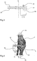
Figure 3 shows the surgical aid offigure 1 in side view; -
Figure 4 shows the surgical aid ofFigure 3 in use configuration; -
Figure 5 shows an example of force/elongation curve for tendons and ligaments; -
figure 6 shows a qualitative example of an angle/shifting curve obtained with the surgical aid according to the present invention. - With reference to the figures listed above, the surgical aid according to the present invention comprises a first element (10) intended to be positioned in contact with a first bone of a joint. In the case of a knee prosthesis, the first bone is the femur (F). In particular, the first element (10) is intended to be positioned in contact with the lower end of the femur. The surgical aid further comprises a second element (20) intended to be positioned in contact with a second bone of the joint. The second bone, in the case of knee implants, is the tibia (T). In particular, the second element (20) is intended to be positioned in contact with the tibia upper end, preferably following performance of a minimal tibial resection.
- The first and second element (10,20) are movable relatively to one another along at least a first direction (X). An actuator or motor (50) is arranged to exert a force which tends to move away the first element (10) and the second element (20) from one another. Such actuator or motor (50) may be interposed between the first and second element (10,20). In the illustrated embodiment, the actuator or motor (50) is associated to one between the first and second element (10,20), for example, the second element (10), and is acting on the second element (20) with an active portion. The actuator or motor (50) comprises for example a hydraulic cylinder and/or a screw mechanism or other system in order to axially space apart the two elements from one another. In this case, the actuator body or motor (50) is associated to the second element (20), whereas the stem or spindle nut is associated to the first element (10).
- The surgical aid comprises a displacement sensor (30), which is predisposed for measuring a relative displacement between the first and second element (10,20). In particular, the displacement sensor (30) measures the relative displacement between the first and second element (10,20) with respect to zero or an initial pre-established position, wherein the first and second element (10,20) are located at a known distance. Essentially, this initial known distance is to be understood as the initial reference wherefrom the space between the tibia and femur is calculated during the entire range of motion. As shown in
Figure 1 , the displacement sensor may be associated to the actuator or motor (50), such that displacement between the first and second element (10,20) may be detected by measuring the stroke performed by the actuator or motor (50). - The surgical aid further comprises a force sensor (51), represented only schematically and predisposed for measuring the force exerted by the actuator or motor (50).
- Preferably the surgical aid further comprises a pressure sensor (40), arranged for detecting a pressure which is acting on the first element (10) and/or second element (20). For example, the pressure sensor (40) may be associated with the first element (10) in an area intended to come into contact with the first bone (F) of the joint. The pressure sensor (40) can be useful for detecting the presence of any peaks of pressure or a possible uneven distribution of pressure, both indicating an incorrect positioning or conformation of the joint. This data is therefore desirable for ascertaining the positioning performed during the full range of motion.
- The displacement sensor (30), the force sensor (51) and the pressure sensor (40), if present, are connected to a processing module (60), which is predisposed for controlling the actuator or motor (50). In particular the processing module (60) in different angular positions or joint flexion-extension all along the range of motion of the knee, progressively increases the force exerted by the actuator/motor (50) by simultaneously detecting the displacement measured by the displacement sensor (30) and developing a force-displacement diagram.
- The isometric tension of the soft tissues is detected by the processing module (60) through an analysis of the force-elongation diagram obtained by reading the force sensor (51), the pressure sensor (40), if present, and the displacement sensor (30) in different angular or flexion-extension positions of the joint. In any pre-determined angular position, the distraction essentially ceases as soon as the force-displacement diagram exhibits a net slope change indicating the end of the isometric condition. For each angular or flexion-extension position selected for the joint, the processing module traces the force/displacement diagram as described above, thereby detecting the critical displacement value based on which the change in the slope of the force/displacement diagram occurs. Such critical displacement, for each selected angular position, substantially corresponds to the maximum distance between femur and tibia, wherein the capsule-ligamentous tissues are in isometric conditions. The number of angular positions or flexion-extension of the joint according to which the variation of the strength and development of the force/displacement diagram shall be performed, can be determined at will.
- In each of the various selected angular positions, the processing module (60) then controls a variation of the force applied by the actuator/motor (50) up to the moment in which the variation of the slope of the force-displacement diagram is detected. At such time the processing module (60) detects the critical displacement between the first and second element (10,20). In this way, for each of the angular positions which were selected for the purposes of detection, the space or maximum tibiofemoral distance is obtained, in which the capsule-ligamentous tissues are in isometric conditions.
- During the range of motion of the knee, in the different selected angular or flexion-extension positions, the processing module (60) is arranged to detect the displacement signal sent by the displacement sensor (30), which corresponds to the critical displacement along the first direction (X), i.e. to the displacement value based on which the change of slope of the force-displacement diagram occurs. The displacement values recorded for each angular position are stored and subsequently processed by means of a pre-determined algorithm, such that an optimal displacement can be obtained which corresponds essentially to a maximum tibiofemoral distance in which the capsule-ligamentous tissues are maintained in conditions of isometric tension, i.e. under conditions in which the capsule-ligamentous tissues are not subjected to a tension higher than that based on which the change of slope of the force-displacement curve is determined. This optimal displacement measured along the first direction (X), basically corresponds to the ideal height of the prosthesis, or at least of the tibial prosthetic component which exhibits a substantially flat articular surface.
- Moreover, once the femoral and/or tibial resection have been performed based on the optimal displacement value between femur and tibia, which value is calculated by the module (60), one may use the surgical aid in order to verify the isometry of tissues throughout the range of motion of the limb. After entering the trial femoral component, the surface of which is compatible with the geometry of the permanent prosthesis, the surgical aid is inserted on the final resection of the tibia, and by moving the knee throughout the range of motion, the force/displacement measurements mentioned above are repeated, and the pressure measured by the sensor (40) possibly detected. Cutting, insert thickness or size of the components may still be modified as a function of the detected measurements for the purposes of trying to get the isometry of the medial and/or lateral capsular-ligamentous tissues throughout the whole range of motion. On the contact surface with the trial component of the femur, the surgical aid preferably exhibits a geometry which is equal to the final one of the tibial insert.
- For the implant of a medial or lateral mono-compartmental prosthesis, the surgical aid according to the invention can be used as detailed hereinafter. The limb is suspended with a grip being exerted on the femur in order that the weight of the thigh does not affect the detection of the force between the femur and tibia.
- Before the definitive resections of the femur and tibia are performed, the surgical aid is inserted between the ends of the articular bones, with the first and second element (10,20) being arranged in contact with the ends of the bones themselves. In order to make this possible, a preliminary resection of the tibia is preferably carried out, by following the mechanical or anatomical axis of the tibia on the frontal and sagittal planes. The femur is retained intact (without bone resection).
- The joint is then brought from full extension to full flexion, for example within a range between 0° (straight leg) and 150°. In a certain pre-determined number of angular positions, the force applied by the actuator/motor (50) is varied and the first and second element (10,20) are moved with respect to one another, up to the point in which the force-displacement curve processed by the processing module (60) is changed from a non-linear trend to a linear trend, wherein the tension value of the isometric capsule-ligamentous tissues is indicated, as well as the corresponding critical displacement value which is stored by the module (60) itself. In each of the angular positions in which the measurement is carried out, the processing module (60) stores the isometric force value (or isometric tension) as well, at which value the trend of the force/ displacement curve is changed from a non-linear trend to a linear trend. Once detections have been completed, or after completion of the articular rotation between the bones, an optimal displacement value (or space) between the femur and tibia is determined by the processing module (60), according to the algorithm already mentioned. The optimal displacement calculated, essentially corresponds to the overall thickness of the prosthesis or at least the prosthetic tibial component, and allows performance of a correct spatial orientation of the same. This enables to obtain a joint kinematics of the prosthetic components which is compatible with the isometry of the capsule-ligament intra and extra articular structures.
- The surgical aid according to the present invention may be further provided with an angular measurement device (35), arranged to measure an angle of inclination between the two bones of the joint, which angular measurement device (35) is connected to the processing module (60). Such angular measurement device may be for example in the form of an inertial sensor. In a possible embodiment, the angular measurement device comprises a pair of inertial sensors (illustrated schematically in
Figure 4 ), arranged to be associated respectively to the femur and the tibia. For example, a first sensor can be associated to the thigh (by means of a band or the like), whereas a second sensor can be associated to the tibia or to the patient's ankle. - The processing module (60) is predisposed for detecting the signals emitted by the displacement sensor (30) and the angular measurement device (35) and for tracing a variation of the displacement along the first direction (X), in function of the angle of inclination between the two bones of the joint. In other words, the processing module (60) is arranged to draw an angle/displacement diagram.
- The angular measuring device (35) may be used advantageously to approximate or to obtain an articular surface of the prosthesis, or at least the prosthetic tibial component.
- In a first possible method of use, after determining the optimal displacement and the isometric tension value according to the previously described mode, it is possible to maintain the force exerted by the actuator or motor (50) to a value corresponding to said isometric tension. By making the articular bones to rotate between two pre-determined angular positions, a displacement between the first and second element (10,20) is produced, which is detected by the displacement sensor (30). At the same time, by means of the angle measurement device (35), the angular displacement between the articular bones is detected. The processing module (60) is able to correlate the displacement between the articular bones along the first direction (X) with the angle of inclination between the articular bones by drawing a curve which is able to define, rather well, the profile of the articular surface of the tibial prosthesis seen in projection on the sagittal plane. The correlation angle/displacement curve thus obtained and illustrated only qualitatively in
Figure 6 , may be used to optimally select a ready-to-use prosthesis, or to shape ex novo a custom-made prosthesis. - In a second possible method of use, the angle of rotation between the articular bones is detected in any angular position based on which it is decided to perform the force- displacement measurement in the manner already described above. For example, starting from a substantially extended leg condition (angle close to 0°) and for a certain number of angular positions up to an angle of 150°, the processing module (60) detects the critical displacement as already described, and puts the latter in correlation with the corresponding angle detected via the sensor (35). In this way, to each angle a respective critical displacement is associated, which critical displacement, as already mentioned, corresponds to the displacement wherein the change of slope of the force-displacement curve occurs; in this manner an angle/displacement trend is delineated which is shown in
Figure 6 , which approximates the profile of the articular surface of the tibial prosthesis seen in the sagittal plane. - In all the procedures herein disclosed, following resections and insertion of the trial femoral component, the surgical aid may be repositioned on the final resection of the tibia and the isometry of the capsule-ligamentous tissues in the medial or lateral compartment may be tested. This allows to make possible changes in bone resections, or to quantify and change the tension of the capsular ligamentous tissues.
- In order that the orientation and extent definition of bone resections with respect to the femur and the tibia are accurate for the patient, relevant data shall be processed with a computer-assisted navigation and/or robotics system, wherein femur and tibia geometric images are obtainable via CT or NMR. The surgical aid may be further used by realizing cutting templates for the anatomical positioning of the femoral and tibial component via CT or NMR images, in order to optimize and possibly change the position of prosthetic components as a function of the optimal ligamentous tension.
- The same technique may be applied in realizing mono-compartmental prosthesis, bi-compartmental-Cruciate-Retaining full prosthesis, as well as posterior-Cruciate-Retaining or replacing posterior-Cruciate full prosthesis, by employing two devices: one medial device and one lateral device. The surgical aid according to the present invention offers important advantages. It allows sizing and accurate positioning of the prosthetic elements, while maintaining the isometry of the capsule-ligamentous tissues. In addition, the surgical aid according to the invention is compact and not invasive. A further important advantage is given by the fact that use of the surgical aid does not request to lengthen the intervention time, since it is enough to place the surgical aid between the ends of the articular bones and perform a complete joint movement for obtaining an optimal positioning and sizing of prosthetic components. The surgical aid may be further employed as an instrument for testing and adjusting orientation of the components and of bone thicknesses removed together with the trial components.
Claims (7)
- A surgical aid for joints, comprising: a first element (10), intended to be positioned in contact with a first bone of a joint; a second element (20), intended to be positioned in contact with a second bone of the joint; the first and second element (10,20) are movable relative to one another along at least a first direction (X); a displacement sensor (30) predisposed for measuring a relative displacement between the first and second element (10, 20); an actuator or motor (50) predisposed for exerting a force that tends to move away the first element (10) and second element (20) from one another; a force sensor (51) suitable for detecting the force exerted by the actuator or motor (50); a processing module (60) which receives in input the signals emitted by the displacement sensors (30) and pressure sensors (40) and which is predisposed for controlling the actuator or motor (50);
wherein the processing module (60) is predisposed for detecting the signals of the displacement sensor (30 and of the force sensor (51) and for processing a force/displacement diagram, which puts into correspondence a force value applied by the actuator or motor (50), which force is obtained from the value detected by the force sensor (51), with a corresponding displacement value detected by the displacement sensor (30);
wherein the processing module (60) is arranged to store, in at least two bending positions, the force/displacement diagram by detecting the displacement wherein the diagram exhibits a change of slope; characterized in that the processing module (60) is provided with an algorithm to process the displacement values recorded and stored for each angular position to obtain a displacement which corresponds to a maximum tibiofemoral distance in which the capsule-ligamentous tissues are maintained in conditions of isometric tension. - A surgical aid according to claim 1, wherein the processing module (60) is arranged to detect on the force/displacement diagram in at least two bending positions, the displacement in which the diagram is changing from a non-linear to a substantially linear trend.
- A surgical aid according to any preceding claim, wherein the processing module (60) is arranged to detect the signals emitted by the displacement sensor (30) and force sensor (51) and, based on the detected signals, to process said force/displacement diagram in pre-determined angular positions between the bones of the joint.
- A surgical aid according to claim 3, wherein the processing module (60) comprises an algorithm for processing said points of the force/ displacement diagrams in pre-determined angular positions in order that an optimal displacement is obtained, which is measured along the first direction (X) corresponding to the height of at least one prosthetic component.
- A surgical aid according to any preceding claim, comprising a pressure sensor (40), which is predisposed for detecting a pressure acting on the first element (10) and /or on the second element (20).
- A surgical aid according to any preceding claim, comprising an angular measurement device arranged to measure an angle of inclination between the two bones of the joint, which angle of inclination is connected to the processing module (60).
- A surgical aid according to claim 6, wherein the processing module (60) is arranged to detect the signals of the displacement sensor (30) and the angular measurement device and to trace a variation of the displacement along the first direction (X) as a function of the angle of inclination between the two bones of the joint.
Applications Claiming Priority (2)
| Application Number | Priority Date | Filing Date | Title |
|---|---|---|---|
| ITMO20150063 | 2015-03-19 | ||
| PCT/IB2016/051534 WO2016147153A1 (en) | 2015-03-19 | 2016-03-18 | A surgical aid for joints |
Publications (2)
| Publication Number | Publication Date |
|---|---|
| EP3270832A1 EP3270832A1 (en) | 2018-01-24 |
| EP3270832B1 true EP3270832B1 (en) | 2019-05-01 |
Family
ID=53189944
Family Applications (1)
| Application Number | Title | Priority Date | Filing Date |
|---|---|---|---|
| EP16719904.1A Active EP3270832B1 (en) | 2015-03-19 | 2016-03-18 | A surgical aid for joints |
Country Status (4)
| Country | Link |
|---|---|
| US (1) | US10537444B2 (en) |
| EP (1) | EP3270832B1 (en) |
| JP (1) | JP2018509208A (en) |
| WO (1) | WO2016147153A1 (en) |
Families Citing this family (17)
| Publication number | Priority date | Publication date | Assignee | Title |
|---|---|---|---|---|
| US7559931B2 (en) | 2003-06-09 | 2009-07-14 | OrthAlign, Inc. | Surgical orientation system and method |
| ES2683029T3 (en) | 2008-07-24 | 2018-09-24 | OrthAlign, Inc. | Joint replacement systems |
| AU2009291743B2 (en) | 2008-09-10 | 2015-02-05 | Orthalign, Inc | Hip surgery systems and methods |
| US10869771B2 (en) | 2009-07-24 | 2020-12-22 | OrthAlign, Inc. | Systems and methods for joint replacement |
| US9649160B2 (en) | 2012-08-14 | 2017-05-16 | OrthAlign, Inc. | Hip replacement navigation system and method |
| WO2016154356A1 (en) * | 2015-03-24 | 2016-09-29 | Omnilife Science, Inc. | Orthopedic joint distraction device |
| WO2018119360A1 (en) | 2016-12-22 | 2018-06-28 | Orthosensor Inc. | Surgical apparatus to support installation of a prosthetic component and method therefore |
| US11266512B2 (en) | 2016-12-22 | 2022-03-08 | Orthosensor Inc. | Surgical apparatus to support installation of a prosthetic component and method therefore |
| US11185425B2 (en) | 2016-12-22 | 2021-11-30 | Orthosensor Inc. | Surgical tensor configured to distribute loading through at least two pivot points |
| US11284873B2 (en) | 2016-12-22 | 2022-03-29 | Orthosensor Inc. | Surgical tensor where each distraction mechanism is supported and aligned by at least two guide shafts |
| US11291437B2 (en) | 2016-12-22 | 2022-04-05 | Orthosensor Inc. | Tilting surgical tensor to support at least one bone cut |
| WO2018170140A1 (en) | 2017-03-14 | 2018-09-20 | Smith & Nephew, Inc. | Systems and methods for measuring bone joint laxity |
| JP7344122B2 (en) * | 2017-03-14 | 2023-09-13 | オースアライン・インコーポレイテッド | Systems and methods for measuring and balancing soft tissue |
| IT201900001987A1 (en) | 2019-02-12 | 2020-08-12 | Ncs Lab S R L | Improved Surgical Aid |
| GB202002918D0 (en) * | 2020-02-28 | 2020-04-15 | Depuy Ireland Ultd Co | Soft tissue balancing in knee replacement |
| WO2021247990A1 (en) * | 2020-06-05 | 2021-12-09 | Smith & Nephew, Inc. | Automatic adjustment of tensioner device |
| CN114847887B (en) * | 2022-07-07 | 2022-12-13 | 北京壹点灵动科技有限公司 | Measuring device for knee joint soft tissue balance and control method thereof |
Family Cites Families (9)
| Publication number | Priority date | Publication date | Assignee | Title |
|---|---|---|---|---|
| US6022377A (en) * | 1998-01-20 | 2000-02-08 | Sulzer Orthopedics Inc. | Instrument for evaluating balance of knee joint |
| FR2858547B1 (en) | 2003-08-05 | 2005-11-04 | Depuy France | DEVICE FOR DYNAMICALLY POWERING A NATURAL OR PROTHETIC KNEE JOINT |
| US8906027B2 (en) * | 2009-03-26 | 2014-12-09 | Martin Roche | System and method for orthopedic distraction and stabilization |
| US7615055B2 (en) * | 2005-03-31 | 2009-11-10 | Depuy Products, Inc. | Method and apparatus for use in balancing ligaments of a knee |
| US8197489B2 (en) * | 2008-06-27 | 2012-06-12 | Depuy Products, Inc. | Knee ligament balancer |
| JP2012500667A (en) * | 2008-08-20 | 2012-01-12 | シンバシブ テクノロジー インコーポレイティッド | Force sensing method for partial and total knee arthroplasty |
| US8556830B2 (en) * | 2009-03-31 | 2013-10-15 | Depuy | Device and method for displaying joint force data |
| EP2429408A1 (en) * | 2009-05-14 | 2012-03-21 | Blue Ortho | Device and method of automatic calibration of a tensor in arthroplasty procedures |
| US20140094715A1 (en) * | 2012-09-28 | 2014-04-03 | Orthosensor Inc. | Distractor for measuring load and position of load applied by the muscular-skeletal system and method therefor |
-
2016
- 2016-03-18 JP JP2017545669A patent/JP2018509208A/en active Pending
- 2016-03-18 WO PCT/IB2016/051534 patent/WO2016147153A1/en active Application Filing
- 2016-03-18 US US15/549,915 patent/US10537444B2/en not_active Expired - Fee Related
- 2016-03-18 EP EP16719904.1A patent/EP3270832B1/en active Active
Non-Patent Citations (1)
| Title |
|---|
| None * |
Also Published As
| Publication number | Publication date |
|---|---|
| JP2018509208A (en) | 2018-04-05 |
| US20180021151A1 (en) | 2018-01-25 |
| EP3270832A1 (en) | 2018-01-24 |
| WO2016147153A1 (en) | 2016-09-22 |
| US10537444B2 (en) | 2020-01-21 |
Similar Documents
| Publication | Publication Date | Title |
|---|---|---|
| EP3270832B1 (en) | A surgical aid for joints | |
| US11712350B2 (en) | Devices and methods to prevent joint instability following arthroplasty | |
| US10548621B2 (en) | System and method for load balancing in knee replacement procedures | |
| EP3383284B1 (en) | Alignment device | |
| JP2007523696A (en) | Computer-aided ligament balancing in total knee arthroplasty | |
| EP2429408A1 (en) | Device and method of automatic calibration of a tensor in arthroplasty procedures | |
| AU2004266089B2 (en) | Device for dynamic tensioning of a natural or prosthetic knee joint | |
| CN113710148A (en) | System and method for robotic soft tissue assessment | |
| Ramsey et al. | Methodological concerns using intra-cortical pins to measure tibiofemoral kinematics | |
| WO2010125474A2 (en) | Device and method of determination of the knee flexion axis in computer assisted surgery | |
| WO2020165787A1 (en) | Improved surgical aid | |
| US20220202511A1 (en) | Patient specific robotic bone implant positioning | |
| Clarke | The non-invasive measurement of knee kinematics in normal, osteoarthritic and prosthetic knees | |
| US11723587B2 (en) | Knee ligament evaluation system and method | |
| Ghijselings et al. | Using a patella reduced technique while balancing a TKA results in restored physiological strain in the collateral ligaments: an ex vivo kinematic analysis | |
| CN115209825A (en) | Soft tissue balancing in knee replacement | |
| Bragdon et al. | Radiostereometric analysis (RSA) studies at Massachusetts General Hospital | |
| Crottet | A force-sensing device for assistance in soft-tissue balancing during knee arthroplasty | |
| BS et al. | RADIOSTEREOMETRIC ANALYSIS (RSA) STUDIES AT MASSACHUSETTS GENERAL HOSPITAL |
Legal Events
| Date | Code | Title | Description |
|---|---|---|---|
| STAA | Information on the status of an ep patent application or granted ep patent |
Free format text: STATUS: THE INTERNATIONAL PUBLICATION HAS BEEN MADE |
|
| PUAI | Public reference made under article 153(3) epc to a published international application that has entered the european phase |
Free format text: ORIGINAL CODE: 0009012 |
|
| STAA | Information on the status of an ep patent application or granted ep patent |
Free format text: STATUS: REQUEST FOR EXAMINATION WAS MADE |
|
| 17P | Request for examination filed |
Effective date: 20170731 |
|
| AK | Designated contracting states |
Kind code of ref document: A1 Designated state(s): AL AT BE BG CH CY CZ DE DK EE ES FI FR GB GR HR HU IE IS IT LI LT LU LV MC MK MT NL NO PL PT RO RS SE SI SK SM TR |
|
| AX | Request for extension of the european patent |
Extension state: BA ME |
|
| DAV | Request for validation of the european patent (deleted) | ||
| DAX | Request for extension of the european patent (deleted) | ||
| STAA | Information on the status of an ep patent application or granted ep patent |
Free format text: STATUS: EXAMINATION IS IN PROGRESS |
|
| 17Q | First examination report despatched |
Effective date: 20180903 |
|
| GRAP | Despatch of communication of intention to grant a patent |
Free format text: ORIGINAL CODE: EPIDOSNIGR1 |
|
| STAA | Information on the status of an ep patent application or granted ep patent |
Free format text: STATUS: GRANT OF PATENT IS INTENDED |
|
| INTG | Intention to grant announced |
Effective date: 20181130 |
|
| GRAS | Grant fee paid |
Free format text: ORIGINAL CODE: EPIDOSNIGR3 |
|
| GRAA | (expected) grant |
Free format text: ORIGINAL CODE: 0009210 |
|
| STAA | Information on the status of an ep patent application or granted ep patent |
Free format text: STATUS: THE PATENT HAS BEEN GRANTED |
|
| AK | Designated contracting states |
Kind code of ref document: B1 Designated state(s): AL AT BE BG CH CY CZ DE DK EE ES FI FR GB GR HR HU IE IS IT LI LT LU LV MC MK MT NL NO PL PT RO RS SE SI SK SM TR |
|
| REG | Reference to a national code |
Ref country code: GB Ref legal event code: FG4D |
|
| REG | Reference to a national code |
Ref country code: CH Ref legal event code: EP Ref country code: AT Ref legal event code: REF Ref document number: 1125917 Country of ref document: AT Kind code of ref document: T Effective date: 20190515 |
|
| REG | Reference to a national code |
Ref country code: DE Ref legal event code: R096 Ref document number: 602016013230 Country of ref document: DE |
|
| REG | Reference to a national code |
Ref country code: IE Ref legal event code: FG4D |
|
| REG | Reference to a national code |
Ref country code: NL Ref legal event code: MP Effective date: 20190501 |
|
| REG | Reference to a national code |
Ref country code: LT Ref legal event code: MG4D |
|
| PG25 | Lapsed in a contracting state [announced via postgrant information from national office to epo] |
Ref country code: HR Free format text: LAPSE BECAUSE OF FAILURE TO SUBMIT A TRANSLATION OF THE DESCRIPTION OR TO PAY THE FEE WITHIN THE PRESCRIBED TIME-LIMIT Effective date: 20190501 Ref country code: NL Free format text: LAPSE BECAUSE OF FAILURE TO SUBMIT A TRANSLATION OF THE DESCRIPTION OR TO PAY THE FEE WITHIN THE PRESCRIBED TIME-LIMIT Effective date: 20190501 Ref country code: LT Free format text: LAPSE BECAUSE OF FAILURE TO SUBMIT A TRANSLATION OF THE DESCRIPTION OR TO PAY THE FEE WITHIN THE PRESCRIBED TIME-LIMIT Effective date: 20190501 Ref country code: FI Free format text: LAPSE BECAUSE OF FAILURE TO SUBMIT A TRANSLATION OF THE DESCRIPTION OR TO PAY THE FEE WITHIN THE PRESCRIBED TIME-LIMIT Effective date: 20190501 Ref country code: NO Free format text: LAPSE BECAUSE OF FAILURE TO SUBMIT A TRANSLATION OF THE DESCRIPTION OR TO PAY THE FEE WITHIN THE PRESCRIBED TIME-LIMIT Effective date: 20190801 Ref country code: AL Free format text: LAPSE BECAUSE OF FAILURE TO SUBMIT A TRANSLATION OF THE DESCRIPTION OR TO PAY THE FEE WITHIN THE PRESCRIBED TIME-LIMIT Effective date: 20190501 Ref country code: SE Free format text: LAPSE BECAUSE OF FAILURE TO SUBMIT A TRANSLATION OF THE DESCRIPTION OR TO PAY THE FEE WITHIN THE PRESCRIBED TIME-LIMIT Effective date: 20190501 Ref country code: PT Free format text: LAPSE BECAUSE OF FAILURE TO SUBMIT A TRANSLATION OF THE DESCRIPTION OR TO PAY THE FEE WITHIN THE PRESCRIBED TIME-LIMIT Effective date: 20190901 |
|
| PG25 | Lapsed in a contracting state [announced via postgrant information from national office to epo] |
Ref country code: LV Free format text: LAPSE BECAUSE OF FAILURE TO SUBMIT A TRANSLATION OF THE DESCRIPTION OR TO PAY THE FEE WITHIN THE PRESCRIBED TIME-LIMIT Effective date: 20190501 Ref country code: BG Free format text: LAPSE BECAUSE OF FAILURE TO SUBMIT A TRANSLATION OF THE DESCRIPTION OR TO PAY THE FEE WITHIN THE PRESCRIBED TIME-LIMIT Effective date: 20190801 Ref country code: GR Free format text: LAPSE BECAUSE OF FAILURE TO SUBMIT A TRANSLATION OF THE DESCRIPTION OR TO PAY THE FEE WITHIN THE PRESCRIBED TIME-LIMIT Effective date: 20190802 Ref country code: RS Free format text: LAPSE BECAUSE OF FAILURE TO SUBMIT A TRANSLATION OF THE DESCRIPTION OR TO PAY THE FEE WITHIN THE PRESCRIBED TIME-LIMIT Effective date: 20190501 |
|
| REG | Reference to a national code |
Ref country code: AT Ref legal event code: MK05 Ref document number: 1125917 Country of ref document: AT Kind code of ref document: T Effective date: 20190501 |
|
| PG25 | Lapsed in a contracting state [announced via postgrant information from national office to epo] |
Ref country code: IS Free format text: LAPSE BECAUSE OF FAILURE TO SUBMIT A TRANSLATION OF THE DESCRIPTION OR TO PAY THE FEE WITHIN THE PRESCRIBED TIME-LIMIT Effective date: 20190901 |
|
| PG25 | Lapsed in a contracting state [announced via postgrant information from national office to epo] |
Ref country code: RO Free format text: LAPSE BECAUSE OF FAILURE TO SUBMIT A TRANSLATION OF THE DESCRIPTION OR TO PAY THE FEE WITHIN THE PRESCRIBED TIME-LIMIT Effective date: 20190501 Ref country code: CZ Free format text: LAPSE BECAUSE OF FAILURE TO SUBMIT A TRANSLATION OF THE DESCRIPTION OR TO PAY THE FEE WITHIN THE PRESCRIBED TIME-LIMIT Effective date: 20190501 Ref country code: EE Free format text: LAPSE BECAUSE OF FAILURE TO SUBMIT A TRANSLATION OF THE DESCRIPTION OR TO PAY THE FEE WITHIN THE PRESCRIBED TIME-LIMIT Effective date: 20190501 Ref country code: DK Free format text: LAPSE BECAUSE OF FAILURE TO SUBMIT A TRANSLATION OF THE DESCRIPTION OR TO PAY THE FEE WITHIN THE PRESCRIBED TIME-LIMIT Effective date: 20190501 Ref country code: AT Free format text: LAPSE BECAUSE OF FAILURE TO SUBMIT A TRANSLATION OF THE DESCRIPTION OR TO PAY THE FEE WITHIN THE PRESCRIBED TIME-LIMIT Effective date: 20190501 Ref country code: SK Free format text: LAPSE BECAUSE OF FAILURE TO SUBMIT A TRANSLATION OF THE DESCRIPTION OR TO PAY THE FEE WITHIN THE PRESCRIBED TIME-LIMIT Effective date: 20190501 |
|
| REG | Reference to a national code |
Ref country code: DE Ref legal event code: R097 Ref document number: 602016013230 Country of ref document: DE |
|
| PG25 | Lapsed in a contracting state [announced via postgrant information from national office to epo] |
Ref country code: IT Free format text: LAPSE BECAUSE OF FAILURE TO SUBMIT A TRANSLATION OF THE DESCRIPTION OR TO PAY THE FEE WITHIN THE PRESCRIBED TIME-LIMIT Effective date: 20190501 Ref country code: SM Free format text: LAPSE BECAUSE OF FAILURE TO SUBMIT A TRANSLATION OF THE DESCRIPTION OR TO PAY THE FEE WITHIN THE PRESCRIBED TIME-LIMIT Effective date: 20190501 |
|
| PLBE | No opposition filed within time limit |
Free format text: ORIGINAL CODE: 0009261 |
|
| STAA | Information on the status of an ep patent application or granted ep patent |
Free format text: STATUS: NO OPPOSITION FILED WITHIN TIME LIMIT |
|
| PG25 | Lapsed in a contracting state [announced via postgrant information from national office to epo] |
Ref country code: TR Free format text: LAPSE BECAUSE OF FAILURE TO SUBMIT A TRANSLATION OF THE DESCRIPTION OR TO PAY THE FEE WITHIN THE PRESCRIBED TIME-LIMIT Effective date: 20190501 |
|
| 26N | No opposition filed |
Effective date: 20200204 |
|
| PG25 | Lapsed in a contracting state [announced via postgrant information from national office to epo] |
Ref country code: PL Free format text: LAPSE BECAUSE OF FAILURE TO SUBMIT A TRANSLATION OF THE DESCRIPTION OR TO PAY THE FEE WITHIN THE PRESCRIBED TIME-LIMIT Effective date: 20190501 |
|
| PG25 | Lapsed in a contracting state [announced via postgrant information from national office to epo] |
Ref country code: SI Free format text: LAPSE BECAUSE OF FAILURE TO SUBMIT A TRANSLATION OF THE DESCRIPTION OR TO PAY THE FEE WITHIN THE PRESCRIBED TIME-LIMIT Effective date: 20190501 |
|
| PG25 | Lapsed in a contracting state [announced via postgrant information from national office to epo] |
Ref country code: ES Free format text: LAPSE BECAUSE OF FAILURE TO SUBMIT A TRANSLATION OF THE DESCRIPTION OR TO PAY THE FEE WITHIN THE PRESCRIBED TIME-LIMIT Effective date: 20190501 Ref country code: MC Free format text: LAPSE BECAUSE OF FAILURE TO SUBMIT A TRANSLATION OF THE DESCRIPTION OR TO PAY THE FEE WITHIN THE PRESCRIBED TIME-LIMIT Effective date: 20190501 |
|
| REG | Reference to a national code |
Ref country code: CH Ref legal event code: PL |
|
| REG | Reference to a national code |
Ref country code: BE Ref legal event code: MM Effective date: 20200331 |
|
| PG25 | Lapsed in a contracting state [announced via postgrant information from national office to epo] |
Ref country code: LU Free format text: LAPSE BECAUSE OF NON-PAYMENT OF DUE FEES Effective date: 20200318 |
|
| PG25 | Lapsed in a contracting state [announced via postgrant information from national office to epo] |
Ref country code: LI Free format text: LAPSE BECAUSE OF NON-PAYMENT OF DUE FEES Effective date: 20200331 Ref country code: CH Free format text: LAPSE BECAUSE OF NON-PAYMENT OF DUE FEES Effective date: 20200331 Ref country code: IE Free format text: LAPSE BECAUSE OF NON-PAYMENT OF DUE FEES Effective date: 20200318 |
|
| PG25 | Lapsed in a contracting state [announced via postgrant information from national office to epo] |
Ref country code: BE Free format text: LAPSE BECAUSE OF NON-PAYMENT OF DUE FEES Effective date: 20200331 |
|
| PGFP | Annual fee paid to national office [announced via postgrant information from national office to epo] |
Ref country code: GB Payment date: 20210326 Year of fee payment: 6 |
|
| PGFP | Annual fee paid to national office [announced via postgrant information from national office to epo] |
Ref country code: DE Payment date: 20220331 Year of fee payment: 7 |
|
| PG25 | Lapsed in a contracting state [announced via postgrant information from national office to epo] |
Ref country code: MT Free format text: LAPSE BECAUSE OF FAILURE TO SUBMIT A TRANSLATION OF THE DESCRIPTION OR TO PAY THE FEE WITHIN THE PRESCRIBED TIME-LIMIT Effective date: 20190501 Ref country code: CY Free format text: LAPSE BECAUSE OF FAILURE TO SUBMIT A TRANSLATION OF THE DESCRIPTION OR TO PAY THE FEE WITHIN THE PRESCRIBED TIME-LIMIT Effective date: 20190501 |
|
| PGFP | Annual fee paid to national office [announced via postgrant information from national office to epo] |
Ref country code: FR Payment date: 20220331 Year of fee payment: 7 |
|
| PG25 | Lapsed in a contracting state [announced via postgrant information from national office to epo] |
Ref country code: MK Free format text: LAPSE BECAUSE OF FAILURE TO SUBMIT A TRANSLATION OF THE DESCRIPTION OR TO PAY THE FEE WITHIN THE PRESCRIBED TIME-LIMIT Effective date: 20190501 |
|
| GBPC | Gb: european patent ceased through non-payment of renewal fee |
Effective date: 20220318 |
|
| PG25 | Lapsed in a contracting state [announced via postgrant information from national office to epo] |
Ref country code: GB Free format text: LAPSE BECAUSE OF NON-PAYMENT OF DUE FEES Effective date: 20220318 |
|
| REG | Reference to a national code |
Ref country code: DE Ref legal event code: R119 Ref document number: 602016013230 Country of ref document: DE |
|
| PG25 | Lapsed in a contracting state [announced via postgrant information from national office to epo] |
Ref country code: FR Free format text: LAPSE BECAUSE OF NON-PAYMENT OF DUE FEES Effective date: 20230331 Ref country code: DE Free format text: LAPSE BECAUSE OF NON-PAYMENT OF DUE FEES Effective date: 20231003 |