EP3270599A1 - Apparatuses and methods for wireless synchronization of multiple multimedia devices using a common timing framework - Google Patents
Apparatuses and methods for wireless synchronization of multiple multimedia devices using a common timing framework Download PDFInfo
- Publication number
- EP3270599A1 EP3270599A1 EP17189008.0A EP17189008A EP3270599A1 EP 3270599 A1 EP3270599 A1 EP 3270599A1 EP 17189008 A EP17189008 A EP 17189008A EP 3270599 A1 EP3270599 A1 EP 3270599A1
- Authority
- EP
- European Patent Office
- Prior art keywords
- multimedia
- pcr
- source device
- sink device
- multimedia sink
- Prior art date
- Legal status (The legal status is an assumption and is not a legal conclusion. Google has not performed a legal analysis and makes no representation as to the accuracy of the status listed.)
- Withdrawn
Links
Images




Classifications
-
- H—ELECTRICITY
- H04—ELECTRIC COMMUNICATION TECHNIQUE
- H04W—WIRELESS COMMUNICATION NETWORKS
- H04W56/00—Synchronisation arrangements
- H04W56/004—Synchronisation arrangements compensating for timing error of reception due to propagation delay
-
- H—ELECTRICITY
- H04—ELECTRIC COMMUNICATION TECHNIQUE
- H04L—TRANSMISSION OF DIGITAL INFORMATION, e.g. TELEGRAPHIC COMMUNICATION
- H04L65/00—Network arrangements, protocols or services for supporting real-time applications in data packet communication
- H04L65/80—Responding to QoS
-
- H—ELECTRICITY
- H04—ELECTRIC COMMUNICATION TECHNIQUE
- H04N—PICTORIAL COMMUNICATION, e.g. TELEVISION
- H04N21/00—Selective content distribution, e.g. interactive television or video on demand [VOD]
- H04N21/40—Client devices specifically adapted for the reception of or interaction with content, e.g. set-top-box [STB]; Operations thereof
- H04N21/41—Structure of client; Structure of client peripherals
- H04N21/4104—Peripherals receiving signals from specially adapted client devices
-
- H—ELECTRICITY
- H04—ELECTRIC COMMUNICATION TECHNIQUE
- H04N—PICTORIAL COMMUNICATION, e.g. TELEVISION
- H04N21/00—Selective content distribution, e.g. interactive television or video on demand [VOD]
- H04N21/40—Client devices specifically adapted for the reception of or interaction with content, e.g. set-top-box [STB]; Operations thereof
- H04N21/41—Structure of client; Structure of client peripherals
- H04N21/4104—Peripherals receiving signals from specially adapted client devices
- H04N21/4112—Peripherals receiving signals from specially adapted client devices having fewer capabilities than the client, e.g. thin client having less processing power or no tuning capabilities
-
- H—ELECTRICITY
- H04—ELECTRIC COMMUNICATION TECHNIQUE
- H04N—PICTORIAL COMMUNICATION, e.g. TELEVISION
- H04N21/00—Selective content distribution, e.g. interactive television or video on demand [VOD]
- H04N21/40—Client devices specifically adapted for the reception of or interaction with content, e.g. set-top-box [STB]; Operations thereof
- H04N21/43—Processing of content or additional data, e.g. demultiplexing additional data from a digital video stream; Elementary client operations, e.g. monitoring of home network or synchronising decoder's clock; Client middleware
- H04N21/4302—Content synchronisation processes, e.g. decoder synchronisation
- H04N21/4305—Synchronising client clock from received content stream, e.g. locking decoder clock with encoder clock, extraction of the PCR packets
-
- H—ELECTRICITY
- H04—ELECTRIC COMMUNICATION TECHNIQUE
- H04N—PICTORIAL COMMUNICATION, e.g. TELEVISION
- H04N21/00—Selective content distribution, e.g. interactive television or video on demand [VOD]
- H04N21/40—Client devices specifically adapted for the reception of or interaction with content, e.g. set-top-box [STB]; Operations thereof
- H04N21/43—Processing of content or additional data, e.g. demultiplexing additional data from a digital video stream; Elementary client operations, e.g. monitoring of home network or synchronising decoder's clock; Client middleware
- H04N21/4302—Content synchronisation processes, e.g. decoder synchronisation
- H04N21/4307—Synchronising the rendering of multiple content streams or additional data on devices, e.g. synchronisation of audio on a mobile phone with the video output on the TV screen
- H04N21/43076—Synchronising the rendering of multiple content streams or additional data on devices, e.g. synchronisation of audio on a mobile phone with the video output on the TV screen of the same content streams on multiple devices, e.g. when family members are watching the same movie on different devices
-
- H—ELECTRICITY
- H04—ELECTRIC COMMUNICATION TECHNIQUE
- H04N—PICTORIAL COMMUNICATION, e.g. TELEVISION
- H04N21/00—Selective content distribution, e.g. interactive television or video on demand [VOD]
- H04N21/40—Client devices specifically adapted for the reception of or interaction with content, e.g. set-top-box [STB]; Operations thereof
- H04N21/43—Processing of content or additional data, e.g. demultiplexing additional data from a digital video stream; Elementary client operations, e.g. monitoring of home network or synchronising decoder's clock; Client middleware
- H04N21/436—Interfacing a local distribution network, e.g. communicating with another STB or one or more peripheral devices inside the home
- H04N21/43615—Interfacing a Home Network, e.g. for connecting the client to a plurality of peripherals
-
- H—ELECTRICITY
- H04—ELECTRIC COMMUNICATION TECHNIQUE
- H04N—PICTORIAL COMMUNICATION, e.g. TELEVISION
- H04N21/00—Selective content distribution, e.g. interactive television or video on demand [VOD]
- H04N21/40—Client devices specifically adapted for the reception of or interaction with content, e.g. set-top-box [STB]; Operations thereof
- H04N21/43—Processing of content or additional data, e.g. demultiplexing additional data from a digital video stream; Elementary client operations, e.g. monitoring of home network or synchronising decoder's clock; Client middleware
- H04N21/436—Interfacing a local distribution network, e.g. communicating with another STB or one or more peripheral devices inside the home
- H04N21/4363—Adapting the video stream to a specific local network, e.g. a Bluetooth® network
- H04N21/43637—Adapting the video stream to a specific local network, e.g. a Bluetooth® network involving a wireless protocol, e.g. Bluetooth®, RF or wireless LAN [IEEE 802.11]
-
- H—ELECTRICITY
- H04—ELECTRIC COMMUNICATION TECHNIQUE
- H04N—PICTORIAL COMMUNICATION, e.g. TELEVISION
- H04N21/00—Selective content distribution, e.g. interactive television or video on demand [VOD]
- H04N21/60—Network structure or processes for video distribution between server and client or between remote clients; Control signalling between clients, server and network components; Transmission of management data between server and client, e.g. sending from server to client commands for recording incoming content stream; Communication details between server and client
- H04N21/63—Control signaling related to video distribution between client, server and network components; Network processes for video distribution between server and clients or between remote clients, e.g. transmitting basic layer and enhancement layers over different transmission paths, setting up a peer-to-peer communication via Internet between remote STB's; Communication protocols; Addressing
- H04N21/647—Control signaling between network components and server or clients; Network processes for video distribution between server and clients, e.g. controlling the quality of the video stream, by dropping packets, protecting content from unauthorised alteration within the network, monitoring of network load, bridging between two different networks, e.g. between IP and wireless
- H04N21/64784—Data processing by the network
-
- H—ELECTRICITY
- H04—ELECTRIC COMMUNICATION TECHNIQUE
- H04W—WIRELESS COMMUNICATION NETWORKS
- H04W56/00—Synchronisation arrangements
- H04W56/001—Synchronization between nodes
- H04W56/0015—Synchronization between nodes one node acting as a reference for the others
-
- H—ELECTRICITY
- H04—ELECTRIC COMMUNICATION TECHNIQUE
- H04J—MULTIPLEX COMMUNICATION
- H04J3/00—Time-division multiplex systems
- H04J3/02—Details
- H04J3/06—Synchronising arrangements
- H04J3/0635—Clock or time synchronisation in a network
- H04J3/0638—Clock or time synchronisation among nodes; Internode synchronisation
- H04J3/0658—Clock or time synchronisation among packet nodes
- H04J3/0661—Clock or time synchronisation among packet nodes using timestamps
- H04J3/0667—Bidirectional timestamps, e.g. NTP or PTP for compensation of clock drift and for compensation of propagation delays
Definitions
- the technology of the disclosure relates generally to operations of a timing framework within wireless multimedia systems.
- wireless mobile devices such as smart phones
- the number and types of applications available for the wireless mobile devices have increased.
- One of the most common types of mobile applications provides for the storage and playback of multimedia content. While earlier generations of such applications have focused on music, the use of video files is also being enabled on newer mobile devices as wireless networks provide greater bandwidth and the mobile devices provide greater processing power.
- a user would typically listen to audio or audio elements within a video file using wired headphones, and later using a wireless headphone set.
- Many wireless headsets initially were designed to work using the Bluetooth® protocol, and this protocol remains popular among many users.
- Wi-Fi Alliance has promulgated the MiracastTM standard, also known as Wi-Fi Display (WFD), to enable wireless screencasting based on underlying 802.11 standards promulgated by the Institute for Electrical and Electronics Engineering (IEEE).
- WFD Wi-Fi Display
- Screencasting according to the Miracast standard enables wireless delivery of audio and video to or from desktops, tablets, smart phones and other devices. For example, a user may echo a display from a phone or tablet onto a television, or share a laptop screen with a conference room projector in real time, as non-limiting examples.
- a method for providing wireless synchronization of multimedia sink devices comprises establishing, by a multimedia source device, a plurality of wireless connections with a corresponding plurality of multimedia sink devices.
- the method further comprises, for each multimedia sink device of the plurality of multimedia sink devices, transmitting a master program clock reference (M PCR ) to the multimedia sink device.
- M PCR master program clock reference
- the method also comprises, for each multimedia sink device, receiving, by the multimedia source device, a local program clock reference (L PCR ) feedback signal from the multimedia sink device.
- L PCR local program clock reference
- the method additionally comprises, for each multimedia sink device, calculating a correction time interval based on a difference between the M PCR at reception and the L PCR feedback signal.
- the method further comprises, for each multimedia sink device, generating presentation time stamp (PTS) data corresponding to a multimedia stream sent to the multimedia sink device, based on the correction time interval.
- PTS presentation time stamp
- the method also comprises, for each multimedia sink device, providing the PTS data to the multimedia sink device.
- a method for synchronizing a multimedia sink device with a multimedia source device comprises establishing, by a multimedia sink device, a wireless connection with a multimedia source device.
- the method further comprises transmitting a program clock reference (PCR) request to the multimedia source device.
- the method also comprises receiving, in response to the PCR request, a correction time interval based on a difference between a M PCR for the multimedia source device and a L PCR for the multimedia sink device.
- the method further comprises calculating an updated L PCR based on the correction time interval.
- the method also comprises receiving a multimedia stream from the multimedia source device.
- the method additionally comprises presenting the multimedia stream based on the updated L PCR .
- a wireless multimedia source device comprises a wireless network interface controller communicatively coupled to an antenna, a system clock, and a control system communicatively coupled to the wireless network interface controller and the system clock.
- the control system is configured to establish, using the wireless network interface controller, a plurality of wireless connections with a corresponding plurality of multimedia sink devices.
- the control system is further configured to, for each multimedia sink device of the plurality of multimedia sink devices, transmit, via the wireless network interface controller, an M PCR provided by the system clock to the multimedia sink device.
- the control system is also configured to, for each multimedia sink device of the plurality of multimedia sink devices, receive, via the wireless network interface controller, an L PCR feedback signal from the multimedia sink device.
- the control system is additionally configured to, for each multimedia sink device of the plurality of multimedia sink devices, calculate a correction time interval based on a difference between the M PCR at reception and the L PCR feedback signal.
- the control system is further configured to, for each multimedia sink device of the plurality of multimedia sink devices, generate PTS data corresponding to a multimedia stream sent to the multimedia sink device, based on the correction time interval.
- the control system is also configured to, for each multimedia sink device of the plurality of multimedia sink devices, provide, via the wireless network interface controller, the PTS data to the multimedia sink device.
- a wireless multimedia sink device comprises a transceiver communicatively coupled to an antenna, a system clock, and a control system communicatively coupled to the transceiver and the system clock.
- the control system is configured to establish, using the transceiver, a wireless connection with a multimedia source device.
- the control system is further configured to transmit, via the transceiver, a PCR request to the multimedia source device.
- the control system is also configured to receive, via the transceiver in response to the PCR request, a correction time interval based on a difference between an M PCR for the multimedia source device and an L PCR provided by the system clock.
- the control system is additionally configured to calculate an updated L PCR based on the correction time interval.
- the control system is further configured to receive, via the transceiver, a multimedia stream from the multimedia source device.
- the control system is also configured to present the multimedia stream based on the updated L PCR .
- a method for providing wireless synchronization of multimedia sink devices comprises establishing, by a multimedia source device, a plurality of wireless connections with a corresponding plurality of multimedia sink devices.
- the method further comprises, for each multimedia sink device of the plurality of multimedia sink devices, transmitting a master program clock reference (M PCR ) to the multimedia sink device.
- M PCR master program clock reference
- the method also comprises, for each multimedia sink device, receiving, by the multimedia source device, a local program clock reference (L PCR ) feedback signal from the multimedia sink device.
- L PCR local program clock reference
- the method additionally comprises, for each multimedia sink device, calculating a correction time interval based on a difference between the M PCR at reception and the L PCR feedback signal.
- the method further comprises, for each multimedia sink device, generating presentation time stamp (PTS) data corresponding to a multimedia stream sent to the multimedia sink device, based on the correction time interval.
- PTS presentation time stamp
- the method also comprises, for each multimedia sink device, providing the PTS data to the multimedia sink device.
- a method for synchronizing a multimedia sink device with a multimedia source device comprises establishing, by a multimedia sink device, a wireless connection with a multimedia source device.
- the method further comprises transmitting a program clock reference (PCR) request to the multimedia source device.
- the method also comprises receiving, in response to the PCR request, a correction time interval based on a difference between a M PCR for the multimedia source device and a L PCR for the multimedia sink device.
- the method further comprises calculating an updated L PCR based on the correction time interval.
- the method also comprises receiving a multimedia stream from the multimedia source device.
- the method additionally comprises presenting the multimedia stream based on the updated L PCR .
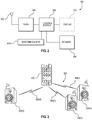
- Figure 1 illustrates an exemplary mobile device that may act as a multimedia source device for providing wireless synchronization
- Figure 2 illustrates elements of an exemplary multimedia sink device
- Figure 3 illustrates an exemplary wireless multimedia system that may incorporate the multimedia source device of Figure 1 and the multimedia sink device of Figure 2
- Figure 4 is a diagram that illustrates issues that may arise with point-to-multipoint wireless multimedia signals in conventional multimedia systems lacking a synchronization mechanism
- a multimedia source device 100 is provided.
- the multimedia source device 100 may comprise, as non-limiting examples, a smart phone or tablet, or other mobile computing device.
- the multimedia source device 100 of Figure 1 includes a receiver path 102, a transmitter path 104, an antenna 106, a switch 108, a baseband processor (BBP) 110, a control system 112, a system clock 113 generating clock signals (not shown), a frequency synthesizer (not shown), a user interface 114, and memory 116 with software 118 stored therein.
- BBP baseband processor
- the elements of the multimedia source device 100 are shown for illustrative purposes only, and that some aspects of the multimedia source device 100 may include more or fewer elements than shown in Figure 1 .
- the receiver path 102 of the multimedia source device 100 may receive information-bearing radio frequency (RF) signals from one or more remote transmitters provided by a base station (not shown), such as a cellular network base station.
- a low noise amplifier (not shown) may amplify the signals.
- a filter (not shown) may minimize broadband interference in the received signals, while down-conversion circuitry (not shown) may down-convert the filtered signals into intermediate or baseband frequency signals, which then may be digitized into one or more digital streams by digitization circuitry (not shown).
- the receiver path 102 may use one or more mixing frequencies generated by the frequency synthesizer.
- the BBP 110 processes the digitized received signal to extract the information (e.g., data bits, as a non-limiting example) conveyed in the signal.
- the BBP 110 may be implemented as one or more digital signal processors (DSPs), as a non-limiting example.
- DSPs digital signal processors
- the BBP 110 may receive digitized data (representing, e.g., voice, data, or control information, as non-limiting examples) from the control system 112, which the BBP 110 then encodes for transmission.
- the encoded data is output to the transmitter path 104, where it may be used by a modulator (not shown) to modulate a carrier signal at a desired transmit frequency.
- An RF power amplifier (not shown) may amplify the modulated carrier signal to a level appropriate for transmission, and may deliver the amplified and modulated carrier signal to the antenna 106 through the switch 108.
- the receiver path 102, the transmitter path 104, and the frequency synthesizer may be considered a wireless modem 120.
- a user may interact with the multimedia source device 100 via the user interface 114.
- the user interface 114 may comprise a microphone, a speaker, a keypad, and/or a display, as non-limiting examples. Some aspects may provide that audio information encoded in the received signal is recovered by the BBP 110, and converted into an analog signal suitable for driving the speaker (not shown).
- the keypad and display of the user interface 114 may enable the user to interact with the multimedia source device 100. For example, the keypad and display may enable the user to input numbers to be dialed, access address book information, and/or monitor call progress information, as non-limiting examples.
- the memory 116 may have the software 118 therein as noted above, which may effectuate exemplary aspects of the present disclosure.
- the multimedia source device 100 may include a wireless network interface controller 122 with its own antenna 124.
- the wireless network interface controller 122 may operate according to a known protocol, such as those published by the Institute for Electrical and Electronics Engineering (IEEE) within the 802.11 family and as promoted by the Wi-Fi Alliance. These protocols may include wireless local area network (WLAN) techniques, popularly known as Wi-Fi systems, that may utilize contention-based carrier sense multiple access with collision avoidance (CSMA/CA) mechanisms to access a wireless medium.
- WLAN wireless local area network
- Wi-Fi systems may utilize contention-based carrier sense multiple access with collision avoidance (CSMA/CA) mechanisms to access a wireless medium.
- CSMA/CA contention-based carrier sense multiple access with collision avoidance
- the wireless network interface controller 122 may have its own transceiver (not shown) having its own transmitter path and its own receiver path (neither shown) and operating with its own BBP, while some aspects may provide that the wireless network interface controller 122 uses the BBP 110.
- Audio and/or video content may be stored in the memory 116, and/or may be retrieved from a remote source (e.g., streamed via a network such as the internet).
- the user may view video content through a display provided by the user interface 114, and/or may listen to audio content through speakers provided by the user interface 114.
- the multimedia source device 100 may stream audio and/or video to a remote multimedia sink device, such as a speaker and/or large screen display.
- a multimedia sink device 200 is illustrated in Figure 2 .
- wireless signals are received and transmitted through an antenna 202 coupled to a transceiver (Tx/Rx) 204.
- the transceiver 204 may include a receiver path, a transmitter path, and a BBP having functionality corresponding to the receiver path 102, the transmitter path 104, and the BBP 110, respectively, of Figure 1 .
- a control system 206 is operatively coupled to the transceiver 204, and may receive instructions embedded within the wireless signals received by the transceiver 204.
- the control system 206 is also coupled to a system clock 207, which may provide a clock signal (not shown) to the control system 206.
- the control system 206 may further be coupled to one or more output devices, including but not limited to a speaker 208 and/or a display 210.
- the multimedia sink device 200 may be a television with the display 210 and speakers 208, or one speaker 208 among a plurality of speakers 208 in, e.g., a surround sound system.
- FIG 3 illustrates an exemplary wireless multimedia system 300 that may provide streaming of multimedia content from a multimedia source device to multiple multimedia sink devices.
- the wireless multimedia system 300 may provide a multimedia source device 302, which in some aspects may comprise the multimedia source device 100 of Figure 1 .
- the wireless multimedia system 300 may further include a plurality of multimedia sink devices 304(0)-304(X), each of which may comprise the multimedia sink device 200 of Figure 2 .
- the multimedia source device 302 communicates with the multimedia sink devices 304(0)-304(X) through wireless signals 306(0)-306(X), respectively.
- the wireless signals 306(0)-306(X) may conform to one of the IEEE 802.11 standards operating under the Wi-Fi designation.
- the wireless signals 306(0)-306(X) of Figure 3 may arrive at different ones of the multimedia sink devices 304(0)-304(X) at different times. This may result in a suboptimal multimedia experience for a user.
- the wireless signals 306(0)-306(X) comprise audio channels of a surround sound system
- different arrival times and differences in the local timing reference of each of the multimedia sink devices 304(0)-304(X) may cause audio playback to be discordant, spoiling the desired surround sound effect.
- Figure 4 is a signal diagram 400 showing the timing of wireless signals transmitted by a multimedia source device, such as the multimedia source device 302 of Figure 3 , and received by two multimedia sink devices, such as the multimedia sink devices 304(0) and 304(1) of Figure 3 .
- horizontal arrows 402, 404(0), and 404(1) represent a local time at each of the multimedia source device 302 and the multimedia sink devices 304(0) and 304(1), respectively.
- the multimedia source device 302 may transmit a signal (e.g., a multimedia stream) to both of the multimedia sink devices 304(0) and 304(1) at a time 406.
- the multimedia sink device 304(0) may receive the signal a time 408, but the multimedia sink device 304(1) may receive the same signal at a later time 410. This may happen, for instance, if the multimedia sink device 304(1) is physically located farther away from the multimedia source device 302 than the multimedia sink device 304(0), or if a processing delay at the multimedia sink device 304(1) is higher. If a time difference 412 is sufficiently large, a user may detect discordance in the presentation of the multimedia stream between the multimedia sink devices 304(0) and 304(1), and may find the quality of the multimedia stream to be unacceptably degraded. Unlike in a point-to-point scenario, the delivery of a common timing reference from the multimedia source device to multiple multimedia sink devices to establish a common timing framework may become difficult due to variable link delays and/or processing time at each multimedia sink device.
- the Wi-Fi protocol includes a media access control (MAC) layer timing framework known as the timing synchronization function (TSF), this timing framework may not be suitable for synchronization of multimedia content handled at upper layers (such as, e.g., the MPEG2 layer) in practice.
- the PCR provided by MPEG2-TS has a relatively precise timing framework that is derived from a 27 MHz clock widely used by devices for transmitting and receiving multimedia streams.
- conventional Wi-Fi systems based on IEEE 802.11 protocols do not query the MPEG2 layer components to make use of PCR timing signals provided by MPEG2-TS, and the TSF timing information is not usually available to upper layers.
- exemplary aspects as disclosed herein employ the MPEG2-TS PCR to assist in providing PTS data for synchronizing presentation of multimedia content by the multimedia sink devices 304(0)-304(X) of Figure 3 .
- delay between the multimedia source device 302 and the multimedia sink devices 304(0)-304(X) may be calculated, and a timing correction signal may be provided to synchronize wirelessly the presentation of a multimedia stream by the multimedia sink devices 304(0)-304(X).
- the multimedia stream may be rendered by the multimedia sink devices 304(0)-304(X) at a synchronized point in time for achieving optimal quality.
- wireless synchronization may be provided by operations carried out by the multimedia source device 302 of Figure 3 .
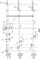
- Figure 5 provides a signal diagram 500 illustrating an exemplary aspect of a wireless synchronization mechanism by which a multimedia source device (e.g., the multimedia source device 302 of Figure 3 ) may wirelessly synchronize multiple multimedia sink devices, such as the multimedia sink devices 304(0)-304(X) of Figure 3 .
- a multimedia source device e.g., the multimedia source device 302 of Figure 3
- the time at the multimedia source device 302 and the multimedia sink devices 304(0) and 304(1) are represented by horizontal arrows 502, 504(0), and 504(1), respectively.
- the labels above the horizontal arrow 502 indicate a value of a master PCR (M PCR ) provided by the multimedia source device 302.
- M PCR master PCR
- the M PCR begins with a value of 1000 and proceeds to a value of 1400. It is assumed that the multimedia source device 302 has successfully established a wireless connection (not shown) with each of the multimedia sink devices 304(0) and 304(1).
- the M PCR may comprise an MPEG2-TS PCR.
- the multimedia source device 302 transmits M PCR s 508 and 510, each representing the current M PCR value, to the multimedia sink devices 304(0) and 304(1), respectively.
- the multimedia sink devices 304(0) and 304(1) will each set its local PCR (L PCR ) to the received M PCR 508 (i.e., 1000).
- L PCR local PCR
- each L PCR comprises an MPEG2-TS PCR.
- the multimedia sink device 304(0) receives the M PCR 508 at a time when the M PCR at the multimedia source device 302 has a value of 1010.
- the multimedia sink device 304(1) receives the M PCR 510 at a time when the M PCR at the multimedia source device 302 has a value of 1020. It is to be understood that the difference in arrival times may result from propagation delays and/or processing delays, as non-limiting factors.
- the multimedia sink device 304(0) transmits an L PCR feedback signal 512 to the multimedia source device 302 at a time when the L PCR of the multimedia sink device 304(0) has a value of 1050, which corresponds to the M PCR having a value of 1060.
- the L PCR feedback signal 512 is received by the multimedia source device 302 at a time when the M PCR has a value of 1070 (as indicated by arrow 514).
- the multimedia sink device 304(0) sends an L PCR feedback signal 516 to the multimedia source device 302 at a time when the L PCR of the multimedia sink device 304(1) has a value of 1080.
- the multimedia source device 302 receives the L PCR feedback signal 516 from the multimedia sink device 304(1) when its master time is 1120 (as indicated by element 518).
- the multimedia source device 302 may calculate correction time intervals 520 and 522 reflecting a path delay for the multimedia sink devices 304(0) and 304(1), respectively.
- the correction time interval 520 calculated for the multimedia sink device 304(0) is 10, which is determined by the difference between the M PCR at reception (i.e., 1070) and the L PCR feedback signal 512 (i.e., 1050), divided by two to account for the round-trip between the multimedia source device 302 and the multimedia sink device 304(0).
- the correction time interval 522 calculated for the multimedia sink device 304(1) is 20 (i.e., the difference between the M PCR at reception (1070) and the L PCR feedback signal 516 (1050), divided by 2).
- the multimedia source device 302 may then generate PTS data 524 and 526 corresponding to a multimedia stream 527 sent to each of the multimedia sink devices 304(0) and 304(1).
- the PTS data 524 and 526 for the multimedia sink devices 304(0) and 304(1) are each customized by the multimedia source device 302 in order to ensure that the multimedia stream 527 is rendered in a synchronized fashion by the multimedia sink devices 304(0) and 304(1).
- the desired PTS for the multimedia sink device having the highest relative delay i.e., the PTS data 526 for the multimedia sink device 304(1)
- the PTS data 526 for the multimedia sink device 304(1) will indicate that the multimedia sink device 304(1) should present the multimedia stream 527 when its L PCR has a value of 1300.
- the correction time interval 520 calculated for the multimedia sink device 304(0) is 10
- the correction time interval 522 calculated for the multimedia sink device 304(1) is 20.
- the PTS data 524 generated for the multimedia sink device 304(0) will have a value of 1310 (i.e., 1300-20+10).
- the PTS data 526 for the multimedia sink device 304(1) is assumed to be 1300, applying the equation above yields the same result (i.e., 1300-20+20).
- the multimedia source device 302 then transmits each PTS data 524, 526 to the respective multimedia sink devices 304(0) and 304(1).
- the multimedia sink devices 304(0) and 304(1) may present the multimedia stream 527 at different L PCR s that correspond to the same M PCR value (i.e., 1320), resulting in a synchronized multimedia presentation.
- each of the multimedia sink devices 304(0) and 304(1) may also provide relative timing offsets 528 and 530, respectively, for one or more past M PCR receptions.
- the multimedia source device 302 may incorporate these relative timing offsets 528 and 530 in calculating each correction time interval 520, 522.
- Some aspects may provide that each of the multimedia sink devices 304(0) and 304(1), upon receiving the M PCR from the multimedia source device 302, may compare its L PCR to the M PCR , and locally track statistics for relative jitters, which may result from variable transmission times from the multimedia sink devices 304(0), 304(1) to the multimedia source device 302.
- Each of the multimedia sink devices 304(0) and 304(1) may also utilize a moving time average or other adaptive algorithm to adjust its L PCR over time using these statistics.
- the multimedia source device 302 may track the relative skews of each of the multimedia sink devices 304(0) and 304(1).
- the multimedia source device 302 may use the relative skews of the multimedia sink devices 304(0) and 304(1) to best align presentation times for the multimedia stream 527 to be sent to each of the multimedia sink devices 304(0) and 304(1).
- the multimedia source device 302 may compute a maximum jitter margin 532 that is required for the multimedia sink devices 304(0) and 304(1). It is to be understood that the multimedia source device 302 may use various time averaging or adaptive algorithms to best estimate this parameter.
- the multimedia source device 302 may include a timing tag 534 within packets that are transferred from one protocol stack layer to another (such as packets used in transmitting and/or receiving an M PCR and/or L PCR feedback signal). This may enable better estimation of timing delays during transmission or reception of the timing packets.
- the timing tag 534 may be used by the multimedia source device 302 to track both when a packet is received by a protocol stack (not shown) or processor subsystem (not shown), and when the packet exits the protocol stack or processor subsystem. In this manner, the internal delays incurred while propagating the packets from a higher protocol stack layer and transmitting the packets may be tracked. This may enable the multimedia source device 302 to more accurately compensate for the link delay when carrying out calculations required for timing synchronization.
- wireless synchronization information may be sent from a multimedia source device (such as the multimedia source device 302 of Figure 3 ) to a multimedia sink device (e.g., each of the multimedia sink devices 304(0)-304(X) of Figure 3 ) at the request of the multimedia sink device, and the multimedia sink device itself may calculate an appropriate delay and/or offset to provide wireless synchronization.
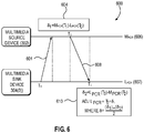
- Figure 6 is a signal diagram 600 provided to illustrate communications between the multimedia source device 302 and the multimedia sink device 304(0) for providing wireless synchronization. While the multimedia sink device 304(0) is referenced for illustrative purposes, it is to be understood that the communications illustrated herein may take place between the multimedia source device 302 and any of the multimedia sink devices 304(0)-304(X) of Figure 3 . It is to be further understood that in the example of Figure 6 , the multimedia source device 302 and the multimedia sink device 304(0) have established a wireless connection (not shown).
- the multimedia sink device 304(0) transmits a PCR request 601 at time To to the multimedia source device 302.
- the PCR request 601 includes an L PCR 602 of the multimedia sink device 304(0), which at this point has the value To.
- the multimedia source device 302 may then calculate a correction time interval 604 of the L PCR 602 relative to an MPC R 606.
- the multimedia source device 302 may respond to the multimedia sink device 304(0) at time T 2 of the M PCR 606 by sending a response 608 comprising the correction time interval 604 (designated as ⁇ 1 ), along with the current value T 2 of the M PCR 606, in some aspects.
- the multimedia sink device 304(0) may then receive the correction time interval 604 at time T 3 of the L PCR 602, and may calculate an updated L PCR 610 to align its local reference with the multimedia source device 302.
- the L PCR 602 and/or the M PCR 606 may comprise an MPEG2-TS PCR.
- the operations illustrated in Figure 6 may take relatively longer to converge to a stable timing alignment among multiple multimedia sink devices 304(0)-304(X) than the source-centric aspect discussed above with respect to Figure 5 .
- this sink-centric aspect shown in Figure 6 has the advantage of being a distributed approach, and consequently the multimedia sink devices 304(0)-304(X) may adjust to any drift in synchronization over time.
- the multimedia source device 302 and the multimedia sink devices 304(0)-304(X) may engage in a negotiation to determine whether the source-centric aspect or the sink-centric aspect technique will be employed for a given multimedia stream.
- the L PCR 602 comprises an MPEG2-TS PCR.
- Figure 7 is provided.
- the time at the multimedia source device 302 and the multimedia sink devices 304(0) and 304(1) are represented by horizontal arrows 702, 704(0), and 704(1), respectively.
- the labels above the horizontal arrow 702 indicate a value of a master PCR (M PCR ) provided by the multimedia source device 302.
- M PCR master PCR
- the M PCR begins with a value of 1000 and proceeds to a value of 1400. It is assumed that the multimedia source device 302 has successfully established a wireless connection (not shown) with each of the multimedia sink devices 304(0) and 304(1).
- the multimedia source device 302 sends out the M PCR at time 1000, as indicated by arrow 706.
- the M PCR is received by the multimedia sink devices 304(0) and 304(1) at varying times, as indicated by arrows 708 and 710.
- each of the multimedia sink devices 304(0) and 304(1) sets its L PCR equal to the M PCR at the time of receipt.
- the multimedia sink device 304(0) subsequently sends a PCR request 712 at its L PCR 1030.
- the PCR request 712 is received at the multimedia source device 302 at a time when its M PCR has a value of 1050, as indicated by arrow 714.
- the multimedia sink device 304(1) sends a PCR request 716 at its L PCR of 1080, which is received at the multimedia source device 302 at its M PCR of 1120, as indicated by arrow 718.
- the multimedia source device 302 calculates and sends a correction time interval 722 for the multimedia sink device 304(0), along with a current M PCR value 724 (i.e., 1060).
- the multimedia sink device 304(0) receives the correction time interval 722 at its L PCR of 1060, corresponding to the M PCR of 1070.
- the correction time interval 722 received from the multimedia source device 302 has a value of 20.
- the multimedia sink device 304(0) calculates an updated L PCR 725 according to the equations described above.
- the updated L PCR 725 is set to the value of the current L PCR (i.e., 1060) summed with a value of the correction time interval 722 (i.e., 20) added to the difference between the current L PCR (i.e., 1060) and the received value of the M PCR (also 1060) divided by 2.
- the updated L PCR 725 thus equals 1060+(20+0)/2, or 1070.
- the multimedia source device 302 calculates and sends a correction time interval 728 for the multimedia sink device 304(1), along with a current M PCR value 730 (i.e., 1130).
- the multimedia sink device 304(1) then receives the correction time interval 728 at its L PCR of 1030, corresponding to the M PCR of 1150.
- the correction time interval 728 received from the multimedia source device 302 has a value of 40.
- the multimedia sink device 304(1) calculates an updated L PCR 731 of 1150.
- the updated L PCR 731 is set to the value of the current L PCR (i.e., 100) summed with a value of the correction time interval 722 (i.e., 40) added to the difference between the current L PCR (i.e., 1130) and the received value of the M PCR (also 1130) divided by 2.
- the updated L PCR 731 thus equals 1130+(40+0)/2, or 1150.
- the multimedia sink devices 304(0) and 304(1) may then receive a multimedia stream 732 from the multimedia source device 302, and may present the multimedia stream 732 based on the respective updated L PCR s 725 and 731, respectively. For instance, when the multimedia sink devices 304(0) and 304(1) receive PTS data 734 and 736, respectively, associated with the multimedia stream 732, the multimedia sink devices 304(0) and 304(1) are correctly synchronized with the multimedia source device 302 and with each other.
- PCR-containing data packets such as PCR feedback or PCR requests
- PSMP power save multipoll
- a multimedia sink device such as the multimedia sink device 304(0), may provide a timing tag 738 within packets that are transferred from one protocol stack layer to another (such as packets used in transmitting and/or receiving a PCR request and/or a correction time interval).
- the timing tag 738 may enable better estimation of timing delays during transmission or reception of the packets.
- the timing tag 738 may be used by the multimedia sink device 304(0) to track both when a packet is received by a protocol stack (not shown) or processor subsystem (not shown), and when the packet exits the protocol stack or processor subsystem. In this manner, the internal delays incurred while propagating the packets from a higher protocol stack layer and transmitting the packets may be tracked. This may enable the multimedia sink device 304(0) to compensate more accurately for the link delay when carrying out calculations required for timing synchronization, and to enhance the accuracy and convergence of synchronization.
- a higher timer synchronization function provided by 802.11 may be employed.
- an upper layer may generate a MAC Layer Management Entity (MLME) Higher Layer (HL) synchronization request (MLME-HL-SYNC.request) to a MAC-service access point (MAC-SAP), along with MAC addresses of the multimedia sink devices 304(0)-304(X) for which timing packets will require tracking of the exact transmit time.
- MLME-HL-SYNC.request MAC Layer Management Entity
- MAC-SAP MAC-service access point
- the upper layer protocol stacks of the participating multimedia sink devices 304(0)-304(X) can track the timing by putting the exact transmit time of a previous packet, along with a unique sequence number, in the next packet.
- FIG 8 is a flowchart illustrating exemplary operations for providing wireless synchronization using a source-based feedback mechanism.
- operations begin with the multimedia source device 302 establishing a plurality of wireless connections with a corresponding plurality of multimedia sink devices 304(0)-304(X) (block 800).
- the operations shown in block 802 are then carried out for each of the plurality of multimedia sink devices 304(0)-304(X).
- the multimedia source device 302 transmits an M PCR 508 to the multimedia sink device 304(0) (block 804).
- the multimedia source device 302 may determine a transmission time of the M PCR 508 based on an 801.11 MLME-HL-SYNC request (block 806). The multimedia source device 302 then receives an L PCR feedback signal 512 from the multimedia sink device 304(0) (block 808).
- the multimedia source device 302 also receives one or more relative timing offsets 528 from the multimedia sink device 304(0) for one or more past M PCR 508 receptions (block 810).
- the multimedia source device 302 may calculate a maximum jitter margin 532 based on one or more past L PCR feedback signal 512 receptions from the multimedia sink device 304(0) (block 812).
- the multimedia source device 302 optionally may estimate timing delays for transmission of the M PCR 508 and reception of each L PCR feedback signal 512 based on one or more timing tags 534 (block 814).
- the multimedia source device 302 then calculates a correction time interval 520 based on a difference between the M PCR at reception and the L PCR feedback signal 512, and optionally on the one or more relative timing offsets 528 and/or the maximum jitter margin 532 (block 816).
- the multimedia source device 302 then generates PTS data 524 corresponding to a multimedia stream 527 sent to the multimedia sink device 304(0) based on the correction time interval 520 (block 818).
- the PTS data 524 is then provided by the multimedia source device 302 to the multimedia sink device 304(0) (block 820).
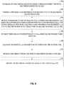
- FIG. 9 To illustrate exemplary operations for providing wireless synchronization using a sink-based feedback mechanism, Figure 9 is provided. For the sake of clarity, elements of Figures 3 , 6 , and 7 are referenced in describing Figure 9 .
- operations begin with the multimedia sink device 304(0) establishing a wireless connection with the multimedia source device 302 (block 900).
- the multimedia sink device 304(0) then transmits a PCR request 712 to the multimedia source device 302 (block 902).
- the multimedia sink device 304(0) receives, in response to the PCR request 712, a correction time interval 722 based on a difference between an M PCR for the multimedia source device 302 and an L PCR for the multimedia sink device 304(0) (block 904).
- the multimedia sink device 304(0) may estimate timing delays for reception of the M PCR based on one or more timing tags 738 (block 906).
- the multimedia sink device 304(0) then calculates an updated L PCR 725 based on the correction time interval 722 (block 908).
- the multimedia sink device 304(0) receive a multimedia stream 732 from the multimedia source device 302 (block 910).
- the multimedia sink device 304(0) presents the multimedia stream 732 based on the updated L PCR 725 (block 912).
- DSP Digital Signal Processor
- ASIC Application Specific Integrated Circuit
- FPGA Field Programmable Gate Array
- a processor may be a microprocessor, but in the alternative, the processor may be any conventional processor, controller, microcontroller, or state machine.
- a processor may also be implemented as a combination of computing devices, e.g., a combination of a DSP and a microprocessor, a plurality of microprocessors, one or more microprocessors in conjunction with a DSP core, or any other such configuration.
- RAM Random Access Memory
- ROM Read Only Memory
- EPROM Electrically Programmable ROM
- EEPROM Electrically Erasable Programmable ROM
- registers a hard disk, a removable disk, a CD-ROM, or any other form of computer readable medium known in the art.
- An exemplary storage medium is coupled to the processor such that the processor can read information from, and write information to, the storage medium.
- the storage medium may be integral to the processor.
- the processor and the storage medium may reside in an ASIC.
- the ASIC may reside in a remote station.
- the processor and the storage medium may reside as discrete components in a remote station, base station, or server.
- a method for providing wireless synchronization of multimedia sink devices may comprise:
- the method may further comprise, for each multimedia sink device of the plurality of multimedia sink devices:
- the method may further comprise, for each multimedia sink device of the plurality of multimedia sink devices:
- the PTS data is generated based on an offset tuning time for each of the plurality of multimedia sink devices.
- the M PCR and the L PCR feedback signal may comprise an MPEG2-TS program clock reference (MPEG2-TS PCR).
- the method may comprise transmitting the M PCR to the multimedia sink device using 802.11n-based power save multi-poll (PSMP) scheduling.
- PSMP power save multi-poll
- the method may further comprise estimating timing delays for transmission of the M PCR and reception of the L PCR feedback signal based on one or more timing tags.
- the method may further comprise determining a wireless transmission time of the M PCR based on an 801.11 MLME-HL-SYNC request.
- a method for synchronizing a multimedia sink device with a multimedia source device may comprise:
- the multimedia stream comprises a Moving Pictures Expert Group version 2 transport stream (MPEG2-TS); and the M PCR and each L PCR comprise an MPEG2-TS program clock reference (MPEG2-TS PCR).
- MPEG2-TS Moving Pictures Expert Group version 2 transport stream
- MPEG2-TS PCR MPEG2-TS program clock reference
- the method may further comprise estimating timing delays for transmission of the PCR request and reception of the correction time interval based on one or more timing tags.
- the wireless multimedia source device may comprise:
- the control system may be further configured to, for each multimedia sink device of the plurality of multimedia sink devices:
- the control system may be further configured to, for each multimedia sink device of the plurality of multimedia sink devices:
- the control system may be configured to generate the PTS data based on an offset tuning time for each of the plurality of multimedia sink devices.
- the M PCR and the L PCR feedback signal may comprise an MPEG2-TS program clock reference (MPEG2-TS PCR).
- the control system may be configured to transmit the M PCR to the multimedia sink device using 802.11n-based power save multipoll (PSMP) scheduling.
- PSMP power save multipoll
- the control system may be further configured to estimate timing delays for transmission of the M PCR and reception of the L PCR feedback signal based on one or more timing tags.
- the control system may be further configured to determine a transmission time of the M PCR based on an 801.11 MLME-HL-SYNC request.
- the wireless multimedia sink device may comprise:
- the multimedia stream may comprise a Moving Pictures Expert Group version 2 transport stream (MPEG2-TS); and the M PCR and the L PCR comprise an MPEG2-TS program clock reference (MPEG2-TS PCR).
- MPEG2-TS Moving Pictures Expert Group version 2 transport stream
- MPEG2-TS PCR MPEG2-TS program clock reference
- the control system may be further configured to estimate timing delays for transmission of the PCR request and reception of the correction time interval based on one or more timing tags.
Landscapes
- Engineering & Computer Science (AREA)
- Signal Processing (AREA)
- Multimedia (AREA)
- Computer Networks & Wireless Communication (AREA)
- Computer Security & Cryptography (AREA)
- Synchronisation In Digital Transmission Systems (AREA)
- Two-Way Televisions, Distribution Of Moving Picture Or The Like (AREA)
- Mobile Radio Communication Systems (AREA)
Abstract
Description
- The present application claims priority to
U.S. Provisional Patent Application Serial No. 61/946,053 filed on February 28, 2014 - The present application also claims priority to U.S. Patent Application Serial No.
14/624,844 filed on February 18, 2015 - The technology of the disclosure relates generally to operations of a timing framework within wireless multimedia systems.
- As the use of wireless mobile devices, such as smart phones, has proliferated, the number and types of applications available for the wireless mobile devices have increased. One of the most common types of mobile applications provides for the storage and playback of multimedia content. While earlier generations of such applications have focused on music, the use of video files is also being enabled on newer mobile devices as wireless networks provide greater bandwidth and the mobile devices provide greater processing power.
- In the earliest aspects of audio- and video-capable mobile devices, a user would typically listen to audio or audio elements within a video file using wired headphones, and later using a wireless headphone set. Many wireless headsets initially were designed to work using the Bluetooth® protocol, and this protocol remains popular among many users. Recently, however, the Wi-Fi Alliance has promulgated the Miracast™ standard, also known as Wi-Fi Display (WFD), to enable wireless screencasting based on underlying 802.11 standards promulgated by the Institute for Electrical and Electronics Engineering (IEEE). Screencasting according to the Miracast standard enables wireless delivery of audio and video to or from desktops, tablets, smart phones and other devices. For example, a user may echo a display from a phone or tablet onto a television, or share a laptop screen with a conference room projector in real time, as non-limiting examples.
- Early efforts to screencast or otherwise wirelessly stream audio to a user were bandwidth-limited, which necessarily resulted in compromises in the quality of the audio so produced. As available bandwidth has increased, so has demand for more sophisticated audio capabilities (e.g., six-, seven-, or eight-channel surround sound, as non-limiting examples). Current standards and protocols may not be suited to provide such sophisticated media capabilities in a wireless context, particularly with regards to synchronization of content streams. In particular, while the existing Miracast standard allows point-to-point communication, it does not support point-to-multipoint communication for sharing multimedia content. Moreover, the Moving Pictures Expert Group
version 2 transport stream (MPEG2-TS)-based timing framework used in the current Miracast standard only provides for synchronization of multimedia streams received by a single multimedia sink device. - Aspects disclosed in the detailed description include apparatuses and methods for wireless synchronization of multiple multimedia devices using a common timing framework. In one aspect, a method for providing wireless synchronization of multimedia sink devices is provided. The method comprises establishing, by a multimedia source device, a plurality of wireless connections with a corresponding plurality of multimedia sink devices. The method further comprises, for each multimedia sink device of the plurality of multimedia sink devices, transmitting a master program clock reference (MPCR) to the multimedia sink device. The method also comprises, for each multimedia sink device, receiving, by the multimedia source device, a local program clock reference (LPCR) feedback signal from the multimedia sink device. The method additionally comprises, for each multimedia sink device, calculating a correction time interval based on a difference between the MPCR at reception and the LPCR feedback signal. The method further comprises, for each multimedia sink device, generating presentation time stamp (PTS) data corresponding to a multimedia stream sent to the multimedia sink device, based on the correction time interval. The method also comprises, for each multimedia sink device, providing the PTS data to the multimedia sink device.
- In another aspect, a method for synchronizing a multimedia sink device with a multimedia source device is provided. The method comprises establishing, by a multimedia sink device, a wireless connection with a multimedia source device. The method further comprises transmitting a program clock reference (PCR) request to the multimedia source device. The method also comprises receiving, in response to the PCR request, a correction time interval based on a difference between a MPCR for the multimedia source device and a LPCR for the multimedia sink device. The method further comprises calculating an updated LPCR based on the correction time interval. The method also comprises receiving a multimedia stream from the multimedia source device. The method additionally comprises presenting the multimedia stream based on the updated LPCR.
- In another aspect, a wireless multimedia source device is provided. The wireless multimedia source device comprises a wireless network interface controller communicatively coupled to an antenna, a system clock, and a control system communicatively coupled to the wireless network interface controller and the system clock. The control system is configured to establish, using the wireless network interface controller, a plurality of wireless connections with a corresponding plurality of multimedia sink devices. The control system is further configured to, for each multimedia sink device of the plurality of multimedia sink devices, transmit, via the wireless network interface controller, an MPCR provided by the system clock to the multimedia sink device. The control system is also configured to, for each multimedia sink device of the plurality of multimedia sink devices, receive, via the wireless network interface controller, an LPCR feedback signal from the multimedia sink device. The control system is additionally configured to, for each multimedia sink device of the plurality of multimedia sink devices, calculate a correction time interval based on a difference between the MPCR at reception and the LPCR feedback signal. The control system is further configured to, for each multimedia sink device of the plurality of multimedia sink devices, generate PTS data corresponding to a multimedia stream sent to the multimedia sink device, based on the correction time interval. The control system is also configured to, for each multimedia sink device of the plurality of multimedia sink devices, provide, via the wireless network interface controller, the PTS data to the multimedia sink device.
- In another aspect, a wireless multimedia sink device is provided. The wireless multimedia sink device comprises a transceiver communicatively coupled to an antenna, a system clock, and a control system communicatively coupled to the transceiver and the system clock. The control system is configured to establish, using the transceiver, a wireless connection with a multimedia source device. The control system is further configured to transmit, via the transceiver, a PCR request to the multimedia source device. The control system is also configured to receive, via the transceiver in response to the PCR request, a correction time interval based on a difference between an MPCR for the multimedia source device and an LPCR provided by the system clock. The control system is additionally configured to calculate an updated LPCR based on the correction time interval. The control system is further configured to receive, via the transceiver, a multimedia stream from the multimedia source device. The control system is also configured to present the multimedia stream based on the updated LPCR.
-
-
Figure 1 is a block diagram of an exemplary multimedia source device for providing wireless synchronization; -
Figure 2 is a block diagram of an exemplary multimedia sink device for providing wireless synchronization; -
Figure 3 is an illustration of an exemplary aspect of a simplified multimedia system including aspects of the multimedia source device ofFigure 1 and the multimedia sink device ofFigure 2 ; -
Figure 4 is a signal diagram illustrating synchronization issues that may arise with point-to-multipoint wireless multimedia signals in conventional multimedia systems lacking a synchronization mechanism; -
Figure 5 is a signal diagram illustrating a source-based feedback system to synchronize multimedia sink devices; -
Figure 6 is a signal diagram illustrating an exemplary sink-based feedback mechanism for providing wireless synchronization; -
Figure 7 is an illustration of a signal diagram illustrating operations of a sink-based feedback mechanism for calculating a delay to assist in synchronization; -
Figure 8 is a flowchart illustrating exemplary operations for providing wireless synchronization using a source-based feedback mechanism; and -
Figure 9 is a flowchart illustrating exemplary operations of a source-based feedback mechanism for providing wireless synchronization. - With reference now to the drawing figures, several exemplary aspects of the present disclosure are described. The word "exemplary" is used herein to mean "serving as an example, instance, or illustration." Any aspect described herein as "exemplary" is not necessarily to be construed as preferred or advantageous over other aspects.
- Aspects disclosed in the detailed description include apparatuses and methods for wireless synchronization of multiple multimedia devices using a common timing framework. In one aspect, a method for providing wireless synchronization of multimedia sink devices is provided. The method comprises establishing, by a multimedia source device, a plurality of wireless connections with a corresponding plurality of multimedia sink devices. The method further comprises, for each multimedia sink device of the plurality of multimedia sink devices, transmitting a master program clock reference (MPCR) to the multimedia sink device. The method also comprises, for each multimedia sink device, receiving, by the multimedia source device, a local program clock reference (LPCR) feedback signal from the multimedia sink device. The method additionally comprises, for each multimedia sink device, calculating a correction time interval based on a difference between the MPCR at reception and the LPCR feedback signal. The method further comprises, for each multimedia sink device, generating presentation time stamp (PTS) data corresponding to a multimedia stream sent to the multimedia sink device, based on the correction time interval. The method also comprises, for each multimedia sink device, providing the PTS data to the multimedia sink device.
- In another aspect, a method for synchronizing a multimedia sink device with a multimedia source device is provided. The method comprises establishing, by a multimedia sink device, a wireless connection with a multimedia source device. The method further comprises transmitting a program clock reference (PCR) request to the multimedia source device. The method also comprises receiving, in response to the PCR request, a correction time interval based on a difference between a MPCR for the multimedia source device and a LPCR for the multimedia sink device. The method further comprises calculating an updated LPCR based on the correction time interval. The method also comprises receiving a multimedia stream from the multimedia source device. The method additionally comprises presenting the multimedia stream based on the updated LPCR.
- Before discussing wireless synchronization of multiple multimedia devices, exemplary mobile devices and point-to-multipoint multimedia systems are described, along with potential undesirable effects that may result from different multimedia stream arrival times and differences in the local timing reference of multimedia sink devices in the multimedia systems. In this regard,
Figures 1-4 are provided.Figure 1 illustrates an exemplary mobile device that may act as a multimedia source device for providing wireless synchronization, whileFigure 2 illustrates elements of an exemplary multimedia sink device.Figure 3 illustrates an exemplary wireless multimedia system that may incorporate the multimedia source device ofFigure 1 and the multimedia sink device ofFigure 2 .Figure 4 is a diagram that illustrates issues that may arise with point-to-multipoint wireless multimedia signals in conventional multimedia systems lacking a synchronization mechanism - In
Figure 1 , amultimedia source device 100 is provided. Themultimedia source device 100 may comprise, as non-limiting examples, a smart phone or tablet, or other mobile computing device. Themultimedia source device 100 ofFigure 1 includes areceiver path 102, atransmitter path 104, anantenna 106, aswitch 108, a baseband processor (BBP) 110, acontrol system 112, asystem clock 113 generating clock signals (not shown), a frequency synthesizer (not shown), auser interface 114, andmemory 116 withsoftware 118 stored therein. It is to be understood that the elements of themultimedia source device 100 are shown for illustrative purposes only, and that some aspects of themultimedia source device 100 may include more or fewer elements than shown inFigure 1 . - In exemplary operation, the
receiver path 102 of themultimedia source device 100 may receive information-bearing radio frequency (RF) signals from one or more remote transmitters provided by a base station (not shown), such as a cellular network base station. A low noise amplifier (not shown) may amplify the signals. A filter (not shown) may minimize broadband interference in the received signals, while down-conversion circuitry (not shown) may down-convert the filtered signals into intermediate or baseband frequency signals, which then may be digitized into one or more digital streams by digitization circuitry (not shown). In some aspects, thereceiver path 102 may use one or more mixing frequencies generated by the frequency synthesizer. TheBBP 110 processes the digitized received signal to extract the information (e.g., data bits, as a non-limiting example) conveyed in the signal. As such, theBBP 110 may be implemented as one or more digital signal processors (DSPs), as a non-limiting example. - With continued reference to
Figure 1 , on the transmit side, theBBP 110 may receive digitized data (representing, e.g., voice, data, or control information, as non-limiting examples) from thecontrol system 112, which theBBP 110 then encodes for transmission. The encoded data is output to thetransmitter path 104, where it may be used by a modulator (not shown) to modulate a carrier signal at a desired transmit frequency. An RF power amplifier (not shown) may amplify the modulated carrier signal to a level appropriate for transmission, and may deliver the amplified and modulated carrier signal to theantenna 106 through theswitch 108. Collectively, thereceiver path 102, thetransmitter path 104, and the frequency synthesizer may be considered awireless modem 120. - Referring still to
Figure 1 , a user (not shown) may interact with themultimedia source device 100 via theuser interface 114. In some aspects, theuser interface 114 may comprise a microphone, a speaker, a keypad, and/or a display, as non-limiting examples. Some aspects may provide that audio information encoded in the received signal is recovered by theBBP 110, and converted into an analog signal suitable for driving the speaker (not shown). In some aspects, the keypad and display of theuser interface 114 may enable the user to interact with themultimedia source device 100. For example, the keypad and display may enable the user to input numbers to be dialed, access address book information, and/or monitor call progress information, as non-limiting examples. Thememory 116 may have thesoftware 118 therein as noted above, which may effectuate exemplary aspects of the present disclosure. - With further reference to
Figure 1 , themultimedia source device 100 may include a wirelessnetwork interface controller 122 with itsown antenna 124. In some aspects, the wirelessnetwork interface controller 122 may operate according to a known protocol, such as those published by the Institute for Electrical and Electronics Engineering (IEEE) within the 802.11 family and as promoted by the Wi-Fi Alliance. These protocols may include wireless local area network (WLAN) techniques, popularly known as Wi-Fi systems, that may utilize contention-based carrier sense multiple access with collision avoidance (CSMA/CA) mechanisms to access a wireless medium. In some aspects, the wirelessnetwork interface controller 122 may have its own transceiver (not shown) having its own transmitter path and its own receiver path (neither shown) and operating with its own BBP, while some aspects may provide that the wirelessnetwork interface controller 122 uses theBBP 110. Audio and/or video content may be stored in thememory 116, and/or may be retrieved from a remote source (e.g., streamed via a network such as the internet). In normal operation, the user may view video content through a display provided by theuser interface 114, and/or may listen to audio content through speakers provided by theuser interface 114. - According to protocols promulgated by the Wi-Fi Alliance, such as Miracast™ (also referred to as Wi-Fi Display or WFD), the
multimedia source device 100 may stream audio and/or video to a remote multimedia sink device, such as a speaker and/or large screen display. In this regard, amultimedia sink device 200 is illustrated inFigure 2 . In the example ofFigure 2 , wireless signals are received and transmitted through anantenna 202 coupled to a transceiver (Tx/Rx) 204. While not illustrated, thetransceiver 204 may include a receiver path, a transmitter path, and a BBP having functionality corresponding to thereceiver path 102, thetransmitter path 104, and theBBP 110, respectively, ofFigure 1 . Acontrol system 206 is operatively coupled to thetransceiver 204, and may receive instructions embedded within the wireless signals received by thetransceiver 204. Thecontrol system 206 is also coupled to asystem clock 207, which may provide a clock signal (not shown) to thecontrol system 206. Thecontrol system 206 may further be coupled to one or more output devices, including but not limited to aspeaker 208 and/or adisplay 210. In exemplary aspects, themultimedia sink device 200 may be a television with thedisplay 210 andspeakers 208, or onespeaker 208 among a plurality ofspeakers 208 in, e.g., a surround sound system. -
Figure 3 illustrates an exemplarywireless multimedia system 300 that may provide streaming of multimedia content from a multimedia source device to multiple multimedia sink devices. As seen inFigure 3 , thewireless multimedia system 300 may provide amultimedia source device 302, which in some aspects may comprise themultimedia source device 100 ofFigure 1 . Thewireless multimedia system 300 may further include a plurality of multimedia sink devices 304(0)-304(X), each of which may comprise themultimedia sink device 200 ofFigure 2 . Themultimedia source device 302 communicates with the multimedia sink devices 304(0)-304(X) through wireless signals 306(0)-306(X), respectively. In some aspects, the wireless signals 306(0)-306(X) may conform to one of the IEEE 802.11 standards operating under the Wi-Fi designation. - As noted above, conventional multimedia systems lack mechanisms for synchronizing multimedia content provided to multiple multimedia sink devices in a point-to-multipoint architecture. In the absence of a synchronization mechanism, the wireless signals 306(0)-306(X) of
Figure 3 may arrive at different ones of the multimedia sink devices 304(0)-304(X) at different times. This may result in a suboptimal multimedia experience for a user. For example, in aspects in which the wireless signals 306(0)-306(X) comprise audio channels of a surround sound system, different arrival times and differences in the local timing reference of each of the multimedia sink devices 304(0)-304(X) may cause audio playback to be discordant, spoiling the desired surround sound effect. - To further illustrate the effect of unsynchronized wireless signals in a conventional multimedia system,
Figure 4 is provided.Figure 4 is a signal diagram 400 showing the timing of wireless signals transmitted by a multimedia source device, such as themultimedia source device 302 ofFigure 3 , and received by two multimedia sink devices, such as the multimedia sink devices 304(0) and 304(1) ofFigure 3 . In the example ofFigure 4 ,horizontal arrows 402, 404(0), and 404(1) represent a local time at each of themultimedia source device 302 and the multimedia sink devices 304(0) and 304(1), respectively. Themultimedia source device 302 may transmit a signal (e.g., a multimedia stream) to both of the multimedia sink devices 304(0) and 304(1) at atime 406. The multimedia sink device 304(0) may receive the signal atime 408, but the multimedia sink device 304(1) may receive the same signal at alater time 410. This may happen, for instance, if the multimedia sink device 304(1) is physically located farther away from themultimedia source device 302 than the multimedia sink device 304(0), or if a processing delay at the multimedia sink device 304(1) is higher. If atime difference 412 is sufficiently large, a user may detect discordance in the presentation of the multimedia stream between the multimedia sink devices 304(0) and 304(1), and may find the quality of the multimedia stream to be unacceptably degraded. Unlike in a point-to-point scenario, the delivery of a common timing reference from the multimedia source device to multiple multimedia sink devices to establish a common timing framework may become difficult due to variable link delays and/or processing time at each multimedia sink device. - While the Wi-Fi protocol includes a media access control (MAC) layer timing framework known as the timing synchronization function (TSF), this timing framework may not be suitable for synchronization of multimedia content handled at upper layers (such as, e.g., the MPEG2 layer) in practice. In contrast, the PCR provided by MPEG2-TS has a relatively precise timing framework that is derived from a 27 MHz clock widely used by devices for transmitting and receiving multimedia streams. However, conventional Wi-Fi systems based on IEEE 802.11 protocols do not query the MPEG2 layer components to make use of PCR timing signals provided by MPEG2-TS, and the TSF timing information is not usually available to upper layers. Thus, exemplary aspects as disclosed herein employ the MPEG2-TS PCR to assist in providing PTS data for synchronizing presentation of multimedia content by the multimedia sink devices 304(0)-304(X) of
Figure 3 . By using the more precise and already existing timing framework of MPEG2-TS PCR as a feedback signal, delay between themultimedia source device 302 and the multimedia sink devices 304(0)-304(X) may be calculated, and a timing correction signal may be provided to synchronize wirelessly the presentation of a multimedia stream by the multimedia sink devices 304(0)-304(X). In this manner, the multimedia stream may be rendered by the multimedia sink devices 304(0)-304(X) at a synchronized point in time for achieving optimal quality. - In some aspects, wireless synchronization may be provided by operations carried out by the
multimedia source device 302 ofFigure 3 . In this regard,Figure 5 provides a signal diagram 500 illustrating an exemplary aspect of a wireless synchronization mechanism by which a multimedia source device (e.g., themultimedia source device 302 ofFigure 3 ) may wirelessly synchronize multiple multimedia sink devices, such as the multimedia sink devices 304(0)-304(X) ofFigure 3 . As seen inFigure 5 , the time at themultimedia source device 302 and the multimedia sink devices 304(0) and 304(1) are represented by horizontal arrows 502, 504(0), and 504(1), respectively. The labels above the horizontal arrow 502 indicate a value of a master PCR (MPCR) provided by themultimedia source device 302. For purposes of illustration, the MPCR begins with a value of 1000 and proceeds to a value of 1400. It is assumed that themultimedia source device 302 has successfully established a wireless connection (not shown) with each of the multimedia sink devices 304(0) and 304(1). In some aspects, the MPCR may comprise an MPEG2-TS PCR. - At a time when the MPCR has a value of 1000 (indicated by arrow 506), the
multimedia source device 302 transmits MPCRs 508 and 510, each representing the current MPCR value, to the multimedia sink devices 304(0) and 304(1), respectively. According to some aspects, the multimedia sink devices 304(0) and 304(1) will each set its local PCR (LPCR) to the received MPCR 508 (i.e., 1000). Some aspects may provide that each LPCR comprises an MPEG2-TS PCR. As shown inFigure 5 , the multimedia sink device 304(0) receives theM PCR 508 at a time when the MPCR at themultimedia source device 302 has a value of 1010. Similarly, the multimedia sink device 304(1) receives theM PCR 510 at a time when the MPCR at themultimedia source device 302 has a value of 1020. It is to be understood that the difference in arrival times may result from propagation delays and/or processing delays, as non-limiting factors. - With continuing reference to
Figure 5 , the multimedia sink device 304(0) then transmits an LPCR feedback signal 512 to themultimedia source device 302 at a time when the LPCR of the multimedia sink device 304(0) has a value of 1050, which corresponds to the MPCR having a value of 1060. The LPCR feedback signal 512 is received by themultimedia source device 302 at a time when the MPCR has a value of 1070 (as indicated by arrow 514). Likewise, the multimedia sink device 304(0) sends an LPCR feedback signal 516 to themultimedia source device 302 at a time when the LPCR of the multimedia sink device 304(1) has a value of 1080. Themultimedia source device 302 receives the LPCR feedback signal 516 from the multimedia sink device 304(1) when its master time is 1120 (as indicated by element 518). - Based on the LPCR feedback signals 512 and 516, the
multimedia source device 302 as shown inFigure 5 may calculatecorrection time intervals correction time intervals 
- Thus, in the example of
Figure 5 , thecorrection time interval 520 calculated for the multimedia sink device 304(0) is 10, which is determined by the difference between the MPCR at reception (i.e., 1070) and the LPCR feedback signal 512 (i.e., 1050), divided by two to account for the round-trip between themultimedia source device 302 and the multimedia sink device 304(0). Similarly, thecorrection time interval 522 calculated for the multimedia sink device 304(1) is 20 (i.e., the difference between the MPCR at reception (1070) and the LPCR feedback signal 516 (1050), divided by 2). - Based on the
correction time intervals multimedia source device 302 may then generatePTS data multimedia stream 527 sent to each of the multimedia sink devices 304(0) and 304(1). ThePTS data multimedia source device 302 in order to ensure that themultimedia stream 527 is rendered in a synchronized fashion by the multimedia sink devices 304(0) and 304(1). ThePTS data multimedia source device 302 based on the following equation, in which adjPTS(k) represents the PTS for a given multimedia sink device, PTS(k) represents the desired PTS value for the multimedia sink device having the highest relative delay, Δmax represents the highest relative delay (i.e., the correction time interval having the largest value), and d(k) represents the correction time interval of the given multimedia sink device:
- In the example of
Figure 5 , to synchronize themultimedia stream 527 to be presented by the multimedia sink devices 304(0) and 304(1), it may be assumed that the desired PTS for the multimedia sink device having the highest relative delay (i.e., thePTS data 526 for the multimedia sink device 304(1)) will be 1300). Stated differently, thePTS data 526 for the multimedia sink device 304(1) will indicate that the multimedia sink device 304(1) should present themultimedia stream 527 when its LPCR has a value of 1300. As noted above, thecorrection time interval 520 calculated for the multimedia sink device 304(0) is 10, while thecorrection time interval 522 calculated for the multimedia sink device 304(1) is 20. Accordingly, using the equation above, thePTS data 524 generated for the multimedia sink device 304(0) will have a value of 1310 (i.e., 1300-20+10). Similarly, although thePTS data 526 for the multimedia sink device 304(1) is assumed to be 1300, applying the equation above yields the same result (i.e., 1300-20+20). Themultimedia source device 302 then transmits eachPTS data multimedia stream 527 at different LPCRs that correspond to the same MPCR value (i.e., 1320), resulting in a synchronized multimedia presentation. - It is to be understood that, in some aspects, in addition to its LPCR, each of the multimedia sink devices 304(0) and 304(1) may also provide relative timing offsets 528 and 530, respectively, for one or more past MPCR receptions. The
multimedia source device 302 may incorporate these relative timing offsets 528 and 530 in calculating eachcorrection time interval multimedia source device 302, may compare its LPCR to the MPCR, and locally track statistics for relative jitters, which may result from variable transmission times from the multimedia sink devices 304(0), 304(1) to themultimedia source device 302. Each of the multimedia sink devices 304(0) and 304(1) may also utilize a moving time average or other adaptive algorithm to adjust its LPCR over time using these statistics. - It is to be further understood that, based on the reception of the LPCR of each of the multimedia sink devices 304(0) and 304(1), the
multimedia source device 302 may track the relative skews of each of the multimedia sink devices 304(0) and 304(1). Themultimedia source device 302 may use the relative skews of the multimedia sink devices 304(0) and 304(1) to best align presentation times for themultimedia stream 527 to be sent to each of the multimedia sink devices 304(0) and 304(1). In some aspects, multimedia content to be transmitted to each multimedia sink device 304(0) and 304(1) may include its own packetized elementary stream (PES) packetization along with timestamps. Accordingly, a maximum presentation hold time to align the multimedia sink devices 304(0) and 304(1) may be expressed as:
- In this manner, the
multimedia source device 302 may compute amaximum jitter margin 532 that is required for the multimedia sink devices 304(0) and 304(1). It is to be understood that themultimedia source device 302 may use various time averaging or adaptive algorithms to best estimate this parameter. - In some applications, there may exist a need to further adjust the presentation times among the multimedia sink devices 304(0) and 304(1) to allow certain offsets in the
PTS data 
- According to some aspects, the
multimedia source device 302 may include atiming tag 534 within packets that are transferred from one protocol stack layer to another (such as packets used in transmitting and/or receiving an MPCR and/or LPCR feedback signal). This may enable better estimation of timing delays during transmission or reception of the timing packets. As a non-limiting example, thetiming tag 534 may be used by themultimedia source device 302 to track both when a packet is received by a protocol stack (not shown) or processor subsystem (not shown), and when the packet exits the protocol stack or processor subsystem. In this manner, the internal delays incurred while propagating the packets from a higher protocol stack layer and transmitting the packets may be tracked. This may enable themultimedia source device 302 to more accurately compensate for the link delay when carrying out calculations required for timing synchronization. - In some aspects, wireless synchronization information may be sent from a multimedia source device (such as the
multimedia source device 302 ofFigure 3 ) to a multimedia sink device (e.g., each of the multimedia sink devices 304(0)-304(X) ofFigure 3 ) at the request of the multimedia sink device, and the multimedia sink device itself may calculate an appropriate delay and/or offset to provide wireless synchronization. In this regard,Figure 6 is a signal diagram 600 provided to illustrate communications between themultimedia source device 302 and the multimedia sink device 304(0) for providing wireless synchronization. While the multimedia sink device 304(0) is referenced for illustrative purposes, it is to be understood that the communications illustrated herein may take place between themultimedia source device 302 and any of the multimedia sink devices 304(0)-304(X) ofFigure 3 . It is to be further understood that in the example ofFigure 6 , themultimedia source device 302 and the multimedia sink device 304(0) have established a wireless connection (not shown). - In the example of
Figure 6 , the multimedia sink device 304(0) transmits aPCR request 601 at time To to themultimedia source device 302. In some aspects, thePCR request 601 includes anL PCR 602 of the multimedia sink device 304(0), which at this point has the value To. Themultimedia source device 302 may then calculate acorrection time interval 604 of theL PCR 602 relative to an MPCR 606. As seen inFigure 6 , thecorrection time interval 604 may be expressed as δ1 = MPCR(T1) - LPCR(T0), and may represent the relative skew observed at themultimedia source device 302. Themultimedia source device 302 may respond to the multimedia sink device 304(0) at time T2 of theM PCR 606 by sending aresponse 608 comprising the correction time interval 604 (designated as δ1), along with the current value T2 of theM PCR 606, in some aspects. The multimedia sink device 304(0) may then receive thecorrection time interval 604 at time T3 of theL PCR 602, and may calculate an updatedL PCR 610 to align its local reference with themultimedia source device 302. In the example ofFigure 6 , the updatedL PCR 610 may be calculated as an adjusted LPCR expressed as adjLPCR= t2 + δ, where δ = (δ1 + δ2)/2 and δ2 = LPCR (t3) - MPCR(t2). According to some aspects, theL PCR 602 and/or theM PCR 606 may comprise an MPEG2-TS PCR. - It is to be understood that the operations illustrated in
Figure 6 may take relatively longer to converge to a stable timing alignment among multiple multimedia sink devices 304(0)-304(X) than the source-centric aspect discussed above with respect toFigure 5 . However, this sink-centric aspect shown inFigure 6 has the advantage of being a distributed approach, and consequently the multimedia sink devices 304(0)-304(X) may adjust to any drift in synchronization over time. It is to be further understood that, in some aspects, themultimedia source device 302 and the multimedia sink devices 304(0)-304(X) may engage in a negotiation to determine whether the source-centric aspect or the sink-centric aspect technique will be employed for a given multimedia stream. Some aspects may provide that theL PCR 602 comprises an MPEG2-TS PCR. - To provide a more detailed signal diagram 700 illustrating an exemplary aspect introduced with reference to
Figure 6 ,Figure 7 is provided. As seen inFigure 7 , the time at themultimedia source device 302 and the multimedia sink devices 304(0) and 304(1) are represented byhorizontal arrows 702, 704(0), and 704(1), respectively. The labels above thehorizontal arrow 702 indicate a value of a master PCR (MPCR) provided by themultimedia source device 302. For purposes of illustration, the MPCR begins with a value of 1000 and proceeds to a value of 1400. It is assumed that themultimedia source device 302 has successfully established a wireless connection (not shown) with each of the multimedia sink devices 304(0) and 304(1). - In
Figure 7 , themultimedia source device 302 sends out the MPCR attime 1000, as indicated byarrow 706. The MPCR is received by the multimedia sink devices 304(0) and 304(1) at varying times, as indicated byarrows PCR request 712 at itsL PCR 1030. ThePCR request 712 is received at themultimedia source device 302 at a time when its MPCR has a value of 1050, as indicated byarrow 714. Similarly, the multimedia sink device 304(1) sends aPCR request 716 at its LPCR of 1080, which is received at themultimedia source device 302 at its MPCR of 1120, as indicated byarrow 718. - At the time point indicated by
element 720, themultimedia source device 302 calculates and sends acorrection time interval 722 for the multimedia sink device 304(0), along with a current MPCR value 724 (i.e., 1060). In this example, the multimedia sink device 304(0) receives thecorrection time interval 722 at its LPCR of 1060, corresponding to the MPCR of 1070. Thecorrection time interval 722 received from themultimedia source device 302 has a value of 20. Based on thecorrection time interval 722, the multimedia sink device 304(0) calculates an updatedL PCR 725 according to the equations described above. In particular, the updatedL PCR 725 is set to the value of the current LPCR (i.e., 1060) summed with a value of the correction time interval 722 (i.e., 20) added to the difference between the current LPCR (i.e., 1060) and the received value of the MPCR (also 1060) divided by 2. The updatedL PCR 725 thus equals 1060+(20+0)/2, or 1070. - Similarly, at the time point indicated by
element 726, themultimedia source device 302 calculates and sends acorrection time interval 728 for the multimedia sink device 304(1), along with a current MPCR value 730 (i.e., 1130). The multimedia sink device 304(1) then receives thecorrection time interval 728 at its LPCR of 1030, corresponding to the MPCR of 1150. Thecorrection time interval 728 received from themultimedia source device 302 has a value of 40. Thus, based on thecorrection time interval 728, the multimedia sink device 304(1) calculates an updatedL PCR 731 of 1150. In particular, the updatedL PCR 731 is set to the value of the current LPCR (i.e., 100) summed with a value of the correction time interval 722 (i.e., 40) added to the difference between the current LPCR (i.e., 1130) and the received value of the MPCR (also 1130) divided by 2. The updatedL PCR 731 thus equals 1130+(40+0)/2, or 1150. - The multimedia sink devices 304(0) and 304(1) may then receive a
multimedia stream 732 from themultimedia source device 302, and may present themultimedia stream 732 based on the respective updated LPCRs 725 and 731, respectively. For instance, when the multimedia sink devices 304(0) and 304(1) receivePTS data multimedia stream 732, the multimedia sink devices 304(0) and 304(1) are correctly synchronized with themultimedia source device 302 and with each other. - For both source- and sink-centric approaches discussed above, convergence of the timing synchronization may take time due to cross-layer processing delays, which may vary based on factors such as operating system loads and variations in processing and transferring network packets containing the timing information. To reduce the initial convergence time, various optional approaches may be employed depending on the implementation platform choice and the chip set. In one aspect, transmission of PCR-containing data packets, such as PCR feedback or PCR requests, among multiple multimedia sink devices 304(0)-304(X) may be scheduled using an 801.11n-based power save multipoll (PSMP) scheduling. In this manner, downlink and uplink transmit times may be allocated to all multimedia sink devices 304(0)-304(X) involved in the synchronized media streaming for transmission and reception of frames containing timing information.
- In some aspects, a multimedia sink device, such as the multimedia sink device 304(0), may provide a
timing tag 738 within packets that are transferred from one protocol stack layer to another (such as packets used in transmitting and/or receiving a PCR request and/or a correction time interval). Thetiming tag 738 may enable better estimation of timing delays during transmission or reception of the packets. For instance, thetiming tag 738 may be used by the multimedia sink device 304(0) to track both when a packet is received by a protocol stack (not shown) or processor subsystem (not shown), and when the packet exits the protocol stack or processor subsystem. In this manner, the internal delays incurred while propagating the packets from a higher protocol stack layer and transmitting the packets may be tracked. This may enable the multimedia sink device 304(0) to compensate more accurately for the link delay when carrying out calculations required for timing synchronization, and to enhance the accuracy and convergence of synchronization. - According to some aspects of both the source- and sink-centric approaches, a higher timer synchronization function provided by 802.11 may be employed. In such aspects, an upper layer may generate a MAC Layer Management Entity (MLME) Higher Layer (HL) synchronization request (MLME-HL-SYNC.request) to a MAC-service access point (MAC-SAP), along with MAC addresses of the multimedia sink devices 304(0)-304(X) for which timing packets will require tracking of the exact transmit time. When such packets with timing information are transmitted, the exact time will be provided to the upper layer using a MLME-HL-SYNC-indication primitive. The upper layer protocol stacks of the participating multimedia sink devices 304(0)-304(X) can track the timing by putting the exact transmit time of a previous packet, along with a unique sequence number, in the next packet.
-
Figure 8 is a flowchart illustrating exemplary operations for providing wireless synchronization using a source-based feedback mechanism. For the sake of clarity, elements ofFigures 3 and5 are referenced in describingFigure 8 . InFigure 8 , operations begin with themultimedia source device 302 establishing a plurality of wireless connections with a corresponding plurality of multimedia sink devices 304(0)-304(X) (block 800). The operations shown inblock 802 are then carried out for each of the plurality of multimedia sink devices 304(0)-304(X). Inblock 802, themultimedia source device 302 transmits anM PCR 508 to the multimedia sink device 304(0) (block 804). In some aspects, themultimedia source device 302 may determine a transmission time of theM PCR 508 based on an 801.11 MLME-HL-SYNC request (block 806). Themultimedia source device 302 then receives an LPCR feedback signal 512 from the multimedia sink device 304(0) (block 808). - Some aspects may provide that the
multimedia source device 302 also receives one or more relative timing offsets 528 from the multimedia sink device 304(0) for one or morepast M PCR 508 receptions (block 810). According to some aspects, themultimedia source device 302 may calculate amaximum jitter margin 532 based on one or more past LPCR feedback signal 512 receptions from the multimedia sink device 304(0) (block 812). In some aspects, themultimedia source device 302 optionally may estimate timing delays for transmission of theM PCR 508 and reception of each LPCR feedback signal 512 based on one or more timing tags 534 (block 814). - The
multimedia source device 302 then calculates acorrection time interval 520 based on a difference between the MPCR at reception and the LPCR feedback signal 512, and optionally on the one or more relative timing offsets 528 and/or the maximum jitter margin 532 (block 816). Themultimedia source device 302 then generatesPTS data 524 corresponding to amultimedia stream 527 sent to the multimedia sink device 304(0) based on the correction time interval 520 (block 818). ThePTS data 524 is then provided by themultimedia source device 302 to the multimedia sink device 304(0) (block 820). - To illustrate exemplary operations for providing wireless synchronization using a sink-based feedback mechanism,
Figure 9 is provided. For the sake of clarity, elements ofFigures 3 ,6 , and7 are referenced in describingFigure 9 . InFigure 9 , operations begin with the multimedia sink device 304(0) establishing a wireless connection with the multimedia source device 302 (block 900). The multimedia sink device 304(0) then transmits aPCR request 712 to the multimedia source device 302 (block 902). The multimedia sink device 304(0) receives, in response to thePCR request 712, acorrection time interval 722 based on a difference between an MPCR for themultimedia source device 302 and an LPCR for the multimedia sink device 304(0) (block 904). In some aspects, the multimedia sink device 304(0) may estimate timing delays for reception of the MPCR based on one or more timing tags 738 (block 906). - The multimedia sink device 304(0) then calculates an updated
L PCR 725 based on the correction time interval 722 (block 908). The multimedia sink device 304(0) receive amultimedia stream 732 from the multimedia source device 302 (block 910). The multimedia sink device 304(0) presents themultimedia stream 732 based on the updated LPCR 725 (block 912). - Those of skill in the art will further appreciate that the various illustrative logical blocks, modules, circuits, and algorithms described in connection with the aspects disclosed herein may be implemented as electronic hardware, instructions stored in memory or in another computer-readable medium and executed by a processor or other processing device, or combinations of both. The devices described herein may be employed in any circuit, hardware component, integrated circuit (IC), or IC chip, as examples. Memory disclosed herein may be any type and size of memory and may be configured to store any type of information desired. To clearly illustrate this interchangeability, various illustrative components, blocks, modules, circuits, and steps have been described above generally in terms of their functionality. How such functionality is implemented depends upon the particular application, design choices, and/or design constraints imposed on the overall system. Skilled artisans may implement the described functionality in varying ways for each particular application, but such implementation decisions should not be interpreted as causing a departure from the scope of the present disclosure.
- The various illustrative logical blocks, modules, and circuits described in connection with the aspects disclosed herein may be implemented or performed with a processor, a Digital Signal Processor (DSP), an Application Specific Integrated Circuit (ASIC), a Field Programmable Gate Array (FPGA) or other programmable logic device, discrete gate or transistor logic, discrete hardware components, or any combination thereof designed to perform the functions described herein. A processor may be a microprocessor, but in the alternative, the processor may be any conventional processor, controller, microcontroller, or state machine. A processor may also be implemented as a combination of computing devices, e.g., a combination of a DSP and a microprocessor, a plurality of microprocessors, one or more microprocessors in conjunction with a DSP core, or any other such configuration.
- The aspects disclosed herein may be embodied in hardware and in instructions that are stored in hardware, and may reside, for example, in Random Access Memory (RAM), flash memory, Read Only Memory (ROM), Electrically Programmable ROM (EPROM), Electrically Erasable Programmable ROM (EEPROM), registers, a hard disk, a removable disk, a CD-ROM, or any other form of computer readable medium known in the art. An exemplary storage medium is coupled to the processor such that the processor can read information from, and write information to, the storage medium. In the alternative, the storage medium may be integral to the processor. The processor and the storage medium may reside in an ASIC. The ASIC may reside in a remote station. In the alternative, the processor and the storage medium may reside as discrete components in a remote station, base station, or server.
- It is also noted that the operational steps described in any of the exemplary aspects herein are described to provide examples and discussion. The operations described may be performed in numerous different sequences other than the illustrated sequences. Furthermore, operations described in a single operational step may actually be performed in a number of different steps. Additionally, one or more operational steps discussed in the exemplary aspects may be combined. It is to be understood that the operational steps illustrated in the flow chart diagrams may be subject to numerous different modifications as will be readily apparent to one of skill in the art. Those of skill in the art will also understand that information and signals may be represented using any of a variety of different technologies and techniques. For example, data, instructions, commands, information, signals, bits, symbols, and chips that may be referenced throughout the above description may be represented by voltages, currents, electromagnetic waves, magnetic fields or particles, optical fields or particles, or any combination thereof.
- The previous description of the disclosure is provided to enable any person skilled in the art to make or use the disclosure. Various modifications to the disclosure will be readily apparent to those skilled in the art, and the generic principles defined herein may be applied to other variations without departing from the spirit or scope of the disclosure. Thus, the disclosure is not intended to be limited to the examples and designs described herein, but is to be accorded the widest scope consistent with the principles and novel features disclosed herein.
- According to a further embodiment of the present invention, there is provided a method for providing wireless synchronization of multimedia sink devices. The method may comprise:
- establishing, by a multimedia source device, a plurality of wireless connections with a corresponding plurality of multimedia sink devices; and
- for each multimedia sink device of the plurality of multimedia sink devices:
- transmitting a master program clock reference (MPCR) to the multimedia sink device;
- receiving, by the multimedia source device, a local program clock reference (LPCR) feedback signal from the multimedia sink device;
- calculating a correction time interval based on a difference between the MPCR at reception and the LPCR feedback signal;
- generating presentation time stamp (PTS) data corresponding to a multimedia stream sent to the multimedia sink device, based on the correction time interval; and
- providing the PTS data to the multimedia sink device.
- The method may further comprise, for each multimedia sink device of the plurality of multimedia sink devices:
- receiving one or more relative timing offsets from the multimedia sink device for one or more past MPCR receptions; and
- calculating the correction time interval further based on the one or more relative timing offsets.
- The method may further comprise, for each multimedia sink device of the plurality of multimedia sink devices:
- calculating a maximum jitter margin based on one or more past LPCR feedback signal receptions from the multimedia sink device; and
- calculating the correction time interval further based on the maximum jitter margin.
- Preferably, the PTS data is generated based on an offset tuning time for each of the plurality of multimedia sink devices.
- The MPCR and the LPCR feedback signal may comprise an MPEG2-TS program clock reference (MPEG2-TS PCR).
- The method may comprise transmitting the MPCR to the multimedia sink device using 802.11n-based power save multi-poll (PSMP) scheduling.
- The method may further comprise estimating timing delays for transmission of the MPCR and reception of the LPCR feedback signal based on one or more timing tags.
- The method may further comprise determining a wireless transmission time of the MPCR based on an 801.11 MLME-HL-SYNC request.
- According to a further embodiment of the present invention, there is provided a method for synchronizing a multimedia sink device with a multimedia source device. The method may comprise:
- establishing, by a multimedia sink device, a wireless connection with a multimedia source device;
- transmitting a program clock reference (PCR) request to the multimedia source device;
- receiving, in response to the PCR request, a correction time interval based on a difference between the MPCR for the multimedia source device and a local program clock reference (LPCR) for the multimedia sink device;
- calculating an updated LPCR based on the correction time interval;
- receiving a multimedia stream from the multimedia source device; and
- presenting the multimedia stream based on the updated LPCR.
- Preferably, the multimedia stream comprises a Moving Pictures
Expert Group version 2 transport stream (MPEG2-TS); and
the MPCR and each LPCR comprise an MPEG2-TS program clock reference (MPEG2-TS PCR). - The method may further comprise estimating timing delays for transmission of the PCR request and reception of the correction time interval based on one or more timing tags.
- According to a further embodiment of the present invention, there is provided a wireless multimedia source device. The wireless multimedia source device may comprise:
- a wireless network interface controller communicatively coupled to an antenna;
- a system clock; and
- a control system communicatively coupled to the wireless network interface controller and the system clock, the control system configured to:
- establish, using the wireless network interface controller, a plurality of wireless connections with a corresponding plurality of multimedia sink devices; and
- for each multimedia sink device of the plurality of multimedia sink devices:
- transmit, via the wireless network interface controller, a master program clock reference (MPCR) provided by the system clock to the multimedia sink device;
- receive, via the wireless network interface controller, a local program clock reference (LPCR) feedback signal from the multimedia sink device;
- calculate a correction time interval based on a difference between the MPCR at reception and the LPCR feedback signal;
- generate presentation time stamp (PTS) data corresponding to a multimedia stream sent to the multimedia sink device, based on the correction time interval; and
- provide, via the wireless network interface controller, the PTS data to the multimedia sink device.
- The control system may be further configured to, for each multimedia sink device of the plurality of multimedia sink devices:
- receive one or more relative timing offsets from the multimedia sink device for one or more past MPCR receptions; and
- calculate the correction time interval further based on the one or more relative timing offsets.
- The control system may be further configured to, for each multimedia sink device of the plurality of multimedia sink devices:
- calculate a maximum jitter margin based on one or more past LPCR feedback signal receptions from the multimedia sink device; and
- calculate the correction time interval further based on the maximum jitter margin.
- The control system may be configured to generate the PTS data based on an offset tuning time for each of the plurality of multimedia sink devices.
- The MPCR and the LPCR feedback signal may comprise an MPEG2-TS program clock reference (MPEG2-TS PCR).
- The control system may be configured to transmit the MPCR to the multimedia sink device using 802.11n-based power save multipoll (PSMP) scheduling.
- The control system may be further configured to estimate timing delays for transmission of the MPCR and reception of the LPCR feedback signal based on one or more timing tags.
- The control system may be further configured to determine a transmission time of the MPCR based on an 801.11 MLME-HL-SYNC request.
- According to a further embodiment of the present invention, there is provided a wireless multimedia sink device. The wireless multimedia sink device may comprise:
- a transceiver communicatively coupled to an antenna;
- a system clock; and
- a control system communicatively coupled to the transceiver and the system clock, the control system configured to:
- establish, using the transceiver, a wireless connection with a multimedia source device;
- transmit, via the transceiver, a program clock reference (PCR) request to the multimedia source device;
- receive, via the transceiver in response to the PCR request, a correction time interval based on a difference between a master program clock reference (MPCR) for the multimedia source device and a local program clock reference (LPCR) provided by the system clock;
- calculate an updated LPCR based on the correction time interval;
- receive, via the transceiver, a multimedia stream from the multimedia source device; and
- present the multimedia stream based on the updated LPCR.
- The multimedia stream may comprise a Moving Pictures
Expert Group version 2 transport stream (MPEG2-TS); and the MPCR and the LPCR comprise an MPEG2-TS program clock reference (MPEG2-TS PCR). - The control system may be further configured to estimate timing delays for transmission of the PCR request and reception of the correction time interval based on one or more timing tags.
Claims (12)
- A method for synchronizing a multimedia sink device with a multimedia source device, comprising:establishing, by a multimedia sink device, a wireless connection with a multimedia source device;transmitting a program clock reference (PCR) request to the multimedia source device;receiving, in response to the PCR request, a correction time interval based on a difference between a master program clock reference (MPCR) for the multimedia source device and a local program clock reference (LPCR) for the multimedia sink device;calculating an updated LPCR based on the correction time interval;receiving a multimedia stream from the multimedia source device; andpresenting the multimedia stream based on the updated LPCR.
- The method of claim 1, wherein the PCR request comprises the LPCR of the multimedia sink device.
- The method of claim 1, wherein the correction time interval represents a relative skew observed at the multimedia source device.
- The method of claim 1, wherein:the multimedia stream comprises a Moving Pictures Expert Group version 2 transport stream (MPEG2-TS); andthe MPCR and each LPCR comprise an MPEG2-TS program clock reference (MPEG2-TS PCR).
- The method of claim 1, wherein the LPCR comprises an MPEG2-TS program clock reference (MPEG2-TS PCR).
- The method of claim 1 comprising scheduling the transmission of PCR-containing data packets among the multiple multimedia sink devices using 801.11n-based power save multi-poll (PSMP) scheduling.
- The method of claim 1, further comprising estimating timing delays for transmission of the PCR request and reception of the correction time interval based on one or more timing tags.
- The method of claim 8 wherein the timing tag is used by the multimedia sink device to track:when a packet is received by a protocol stack or processor subsystem; and/orwhen a packet exits the protocol stack or processor subsystem.
- The method of claim 1, further comprising:generating, by an upper protocol stack layer, a media access control (MAC) layer management entity (MLME) higher layer (HL) synchronization request (MLME-HL-SYNC.request) to a MAC-service access point (MAC-SAP) and MAC addresses of the multimedia sink devices for which timing packets will require tracking of the exact transmit time.
- A wireless multimedia sink device, comprising:a transceiver communicatively coupled to an antenna;a system clock; anda control system communicatively coupled to the transceiver and the system clock, the control system configured to:establish, using the transceiver, a wireless connection with a multimedia source device;transmit, via the transceiver, a program clock reference (PCR) request to the multimedia source device;receive, via the transceiver in response to the PCR request, a correction time interval based on a difference between a master program clock reference (MPCR) for the multimedia source device and a local program clock reference (LPCR) provided by the system clock;calculate an updated LPCR based on the correction time interval;receive, via the transceiver, a multimedia stream from the multimedia source device; andpresent the multimedia stream based on the updated LPCR.
- The wireless multimedia sink device of claim 10, wherein:the multimedia stream comprises a Moving Pictures Expert Group version 2 transport stream (MPEG2-TS); andthe MPCR and the LPCR comprise an MPEG2-TS program clock reference (MPEG2-TS PCR).
- The wireless multimedia sink device of claim 11, wherein the control system is further configured to estimate timing delays for transmission of the PCR request and reception of the correction time interval based on one or more timing tags.
Applications Claiming Priority (3)
| Application Number | Priority Date | Filing Date | Title |
|---|---|---|---|
| US201461946053P | 2014-02-28 | 2014-02-28 | |
| US14/624,844 US9736806B2 (en) | 2014-02-28 | 2015-02-18 | Apparatuses and methods for wireless synchronization of multiple multimedia devices using a common timing framework |
| EP15708980.6A EP3111660A1 (en) | 2014-02-28 | 2015-02-19 | Apparatuses and methods for wireless synchronization of multiple multimedia devices using a common timing framework |
Related Parent Applications (1)
| Application Number | Title | Priority Date | Filing Date |
|---|---|---|---|
| EP15708980.6A Division EP3111660A1 (en) | 2014-02-28 | 2015-02-19 | Apparatuses and methods for wireless synchronization of multiple multimedia devices using a common timing framework |
Publications (1)
| Publication Number | Publication Date |
|---|---|
| EP3270599A1 true EP3270599A1 (en) | 2018-01-17 |
Family
ID=54007397
Family Applications (2)
| Application Number | Title | Priority Date | Filing Date |
|---|---|---|---|
| EP17189008.0A Withdrawn EP3270599A1 (en) | 2014-02-28 | 2015-02-19 | Apparatuses and methods for wireless synchronization of multiple multimedia devices using a common timing framework |
| EP15708980.6A Withdrawn EP3111660A1 (en) | 2014-02-28 | 2015-02-19 | Apparatuses and methods for wireless synchronization of multiple multimedia devices using a common timing framework |
Family Applications After (1)
| Application Number | Title | Priority Date | Filing Date |
|---|---|---|---|
| EP15708980.6A Withdrawn EP3111660A1 (en) | 2014-02-28 | 2015-02-19 | Apparatuses and methods for wireless synchronization of multiple multimedia devices using a common timing framework |
Country Status (6)
| Country | Link |
|---|---|
| US (1) | US9736806B2 (en) |
| EP (2) | EP3270599A1 (en) |
| JP (1) | JP6313466B2 (en) |
| KR (1) | KR101845186B1 (en) |
| CN (1) | CN106063286A (en) |
| WO (1) | WO2015130546A1 (en) |
Families Citing this family (10)
| Publication number | Priority date | Publication date | Assignee | Title |
|---|---|---|---|---|
| GB2525929B (en) | 2014-05-09 | 2016-08-10 | Imagination Tech Ltd | Time stamp replication within a wireless network |
| US10129839B2 (en) * | 2014-12-05 | 2018-11-13 | Qualcomm Incorporated | Techniques for synchronizing timing of wireless streaming transmissions to multiple sink devices |
| BR112019004977A2 (en) | 2016-09-23 | 2019-06-04 | Sony Corp | wireless device, processing method for a wireless device, and program. |
| US10296286B2 (en) | 2016-12-13 | 2019-05-21 | EVA Automation, Inc. | Maintaining coordination following a wireless reset |
| US10901684B2 (en) | 2016-12-13 | 2021-01-26 | EVA Automation, Inc. | Wireless inter-room coordination of audio playback |
| US10255032B2 (en) | 2016-12-13 | 2019-04-09 | EVA Automation, Inc. | Wireless coordination of audio sources |
| CN110098884B (en) * | 2018-01-31 | 2021-05-18 | 慧与发展有限责任合伙企业 | Method and apparatus for determining an anomalous clock |
| KR102001550B1 (en) * | 2018-04-02 | 2019-07-18 | 주식회사 인켈 | Multi room speaker system and data sync method thereof |
| TW202214806A (en) | 2020-09-30 | 2022-04-16 | 日商太陽油墨製造股份有限公司 | Anisotropic conductive connecting material and installing method of electronic component using anisotropic conductive connecting material |
| CN117676219A (en) * | 2022-08-29 | 2024-03-08 | 华为技术有限公司 | A data transmission method and device |
Citations (2)
| Publication number | Priority date | Publication date | Assignee | Title |
|---|---|---|---|---|
| US20090010283A1 (en) * | 2007-07-03 | 2009-01-08 | Arcadyan Technology Corporation | Synchronization method of electronic apparatuses |
| EP2253087A1 (en) * | 2008-03-12 | 2010-11-24 | Genelec OY | Data transfer method and system for loudspeakers in a digital sound reproduction system |
Family Cites Families (21)
| Publication number | Priority date | Publication date | Assignee | Title |
|---|---|---|---|---|
| JP4062504B2 (en) * | 2002-09-09 | 2008-03-19 | ソニー株式会社 | Synchronization method, communication system, and data receiving apparatus |
| US7545794B2 (en) | 2003-08-14 | 2009-06-09 | Intel Corporation | Timestamping network controller for streaming media applications |
| JP4219930B2 (en) * | 2003-09-10 | 2009-02-04 | 富士通株式会社 | Transmission parameter control device |
| US7657645B2 (en) * | 2004-02-05 | 2010-02-02 | Sharp Laboratories Of America, Inc. | System and method for transporting MPEG2TS in RTP/UDP/IP |
| JP2006244060A (en) * | 2005-03-02 | 2006-09-14 | Mitsubishi Electric Corp | Content distribution apparatus, content presentation terminal, request terminal, and content synchronous distribution program |
| US7733835B2 (en) * | 2005-07-20 | 2010-06-08 | Interdigital Technology Corporation | Method and system for reducing power consumption of a wireless transmit/receive unit |
| KR100801002B1 (en) | 2006-06-05 | 2008-02-11 | 삼성전자주식회사 | Method for transmitting / reproducing multimedia data on wireless network, and wireless device using the method |
| US20080178243A1 (en) | 2007-01-19 | 2008-07-24 | Suiwu Dong | Multimedia client/server system with audio synchronization and methods for use therewith |
| US7877514B2 (en) | 2007-05-03 | 2011-01-25 | Samsung Electronics Co., Ltd. | System and method for time-constrained transmission of video in a communication system |
| US8102836B2 (en) | 2007-05-23 | 2012-01-24 | Broadcom Corporation | Synchronization of a split audio, video, or other data stream with separate sinks |
| WO2009011087A1 (en) * | 2007-07-13 | 2009-01-22 | Panasonic Corporation | Video/audio delivering server, video displaying apparatus, audio outputting apparatus, video/audio providing system, and video/audio synchronizing method |
| US7885270B2 (en) | 2008-05-15 | 2011-02-08 | Verlvue, Inc. | Statistical multiplexing of compressed video streams |
| KR20100124909A (en) * | 2009-05-20 | 2010-11-30 | 삼성전자주식회사 | Apparatus and method for synchronization between video and audio in mobile communication terminal |
| US8345681B2 (en) * | 2009-09-23 | 2013-01-01 | Samsung Electronics Co., Ltd. | Method and system for wireless communication of audio in wireless networks |
| CN102185998B (en) * | 2010-12-31 | 2013-05-22 | 北京中科大洋科技发展股份有限公司 | A Method for Synchronizing Video Signals Using AES/EBU Digital Audio Signals |
| US9712573B2 (en) * | 2011-09-13 | 2017-07-18 | Qualcomm Incorporated | Synchronized wireless display devices |
| US9525998B2 (en) | 2012-01-06 | 2016-12-20 | Qualcomm Incorporated | Wireless display with multiscreen service |
| KR102050984B1 (en) | 2012-03-11 | 2019-12-02 | 삼성전자주식회사 | Method and apparatus for providing a wi-fi display session in a wi-fi display network, and system thereof |
| GB2502576B (en) * | 2012-05-31 | 2014-11-12 | Canon Kk | Method, device, computer program and information storage means for optimizing access to a wireless medium in a communication network |
| US10158690B2 (en) | 2012-09-28 | 2018-12-18 | Samsung Electronics Co., Ltd | Method and system for streaming multimedia content in a wireless fidelity display network environment |
| US9426423B2 (en) * | 2012-11-01 | 2016-08-23 | Polycom, Inc. | Method and system for synchronizing audio and video streams in media relay conferencing |
-
2015
- 2015-02-18 US US14/624,844 patent/US9736806B2/en not_active Expired - Fee Related
- 2015-02-19 JP JP2016553607A patent/JP6313466B2/en active Active
- 2015-02-19 EP EP17189008.0A patent/EP3270599A1/en not_active Withdrawn
- 2015-02-19 WO PCT/US2015/016601 patent/WO2015130546A1/en not_active Ceased
- 2015-02-19 KR KR1020167023763A patent/KR101845186B1/en not_active Expired - Fee Related
- 2015-02-19 EP EP15708980.6A patent/EP3111660A1/en not_active Withdrawn
- 2015-02-19 CN CN201580010573.5A patent/CN106063286A/en active Pending
Patent Citations (2)
| Publication number | Priority date | Publication date | Assignee | Title |
|---|---|---|---|---|
| US20090010283A1 (en) * | 2007-07-03 | 2009-01-08 | Arcadyan Technology Corporation | Synchronization method of electronic apparatuses |
| EP2253087A1 (en) * | 2008-03-12 | 2010-11-24 | Genelec OY | Data transfer method and system for loudspeakers in a digital sound reproduction system |
Non-Patent Citations (3)
| Title |
|---|
| ANEEQ MAHMOOD ET AL: "Timestamping for IEEE 1588 based clock synchronization in wireless LAN", PRECISION CLOCK SYNCHRONIZATION FOR MEASUREMENT, CONTROL AND COMMUNICATION, 2009. ISPCS 2009. INTERNATIONAL SYMPOSIUM ON, IEEE, PISCATAWAY, NJ, USA, 12 October 2009 (2009-10-12), pages 1 - 6, XP031570870, ISBN: 978-1-4244-4391-8 * |
| TSAO S L ET AL: "A survey of energy efficient MAC protocols for IEEE 802.11 WLAN", COMPUTER COMMUNICATIONS, ELSEVIER SCIENCE PUBLISHERS BV, AMSTERDAM, NL, vol. 34, no. 1, 15 January 2011 (2011-01-15), pages 54 - 67, XP027476828, ISSN: 0140-3664, [retrieved on 20100922], DOI: 10.1016/J.COMCOM.2010.09.008 * |
| WI-FI ALLIANCE: "Wi-Fi Alliance Technical Committee Wi-Fi Display Technical Task Group Wi-Fi Display Technical Specification", 1 January 2012 (2012-01-01), XP055320680, Retrieved from the Internet <URL:https://www.wi-fi.org/discover-wi-fi/specifications> [retrieved on 20161117] * |
Also Published As
| Publication number | Publication date |
|---|---|
| JP6313466B2 (en) | 2018-04-18 |
| CN106063286A (en) | 2016-10-26 |
| EP3111660A1 (en) | 2017-01-04 |
| JP2017512414A (en) | 2017-05-18 |
| US20150249967A1 (en) | 2015-09-03 |
| KR101845186B1 (en) | 2018-04-03 |
| WO2015130546A1 (en) | 2015-09-03 |
| US9736806B2 (en) | 2017-08-15 |
| KR20160127010A (en) | 2016-11-02 |
Similar Documents
| Publication | Publication Date | Title |
|---|---|---|
| US9736806B2 (en) | Apparatuses and methods for wireless synchronization of multiple multimedia devices using a common timing framework | |
| US8155157B2 (en) | Method and apparatus for synchronizing applications of terminals in communication network | |
| US10129839B2 (en) | Techniques for synchronizing timing of wireless streaming transmissions to multiple sink devices | |
| US10453474B2 (en) | Wireless audio synchronization | |
| US20050152330A1 (en) | Clock recovery methods and apparatus | |
| US20120087503A1 (en) | Multi-channel audio over standard wireless protocol | |
| US20250220603A1 (en) | Synchronization of multi-modal flows | |
| CN112314017A (en) | Time-synchronized radio bearer for supporting Precision Timing Protocol (PTP) based Time Sensitive Networking (TSN) applications | |
| US9167545B2 (en) | Receiver, method of calculating time difference, and program | |
| US11606408B2 (en) | Audio synchronization in wireless systems | |
| TW201731271A (en) | Method and apparatus for synchronizing mobile station media flows during a collaborative session | |
| US20260067406A1 (en) | Synchronizing audio streams for conferencing environments involving multiple microphones in proximity | |
| WO2014188664A1 (en) | Broadcast system, client, synchronization program, and synchronization method | |
| US20260040248A1 (en) | Systems and methods for synchronization of audio streams | |
| CN103354992B (en) | Method and apparatus for synchronizing mobile station media streams during a collaborative session |
Legal Events
| Date | Code | Title | Description |
|---|---|---|---|
| PUAI | Public reference made under article 153(3) epc to a published international application that has entered the european phase |
Free format text: ORIGINAL CODE: 0009012 |
|
| 17P | Request for examination filed |
Effective date: 20170901 |
|
| AC | Divisional application: reference to earlier application |
Ref document number: 3111660 Country of ref document: EP Kind code of ref document: P |
|
| AK | Designated contracting states |
Kind code of ref document: A1 Designated state(s): AL AT BE BG CH CY CZ DE DK EE ES FI FR GB GR HR HU IE IS IT LI LT LU LV MC MK MT NL NO PL PT RO RS SE SI SK SM TR |
|
| STAA | Information on the status of an ep patent application or granted ep patent |
Free format text: STATUS: THE APPLICATION IS DEEMED TO BE WITHDRAWN |
|
| 18D | Application deemed to be withdrawn |
Effective date: 20190903 |