EP3270148A1 - Parallel plate-type non-uniform electric field ion mobility spectrometry device - Google Patents
Parallel plate-type non-uniform electric field ion mobility spectrometry device Download PDFInfo
- Publication number
- EP3270148A1 EP3270148A1 EP15884526.3A EP15884526A EP3270148A1 EP 3270148 A1 EP3270148 A1 EP 3270148A1 EP 15884526 A EP15884526 A EP 15884526A EP 3270148 A1 EP3270148 A1 EP 3270148A1
- Authority
- EP
- European Patent Office
- Prior art keywords
- ion
- electrodes
- ions
- voltage
- plate
- Prior art date
- Legal status (The legal status is an assumption and is not a legal conclusion. Google has not performed a legal analysis and makes no representation as to the accuracy of the status listed.)
- Granted
Links
- 230000005684 electric field Effects 0.000 title claims abstract description 140
- 238000001871 ion mobility spectroscopy Methods 0.000 title description 3
- 150000002500 ions Chemical class 0.000 claims abstract description 336
- 238000000926 separation method Methods 0.000 claims abstract description 81
- 238000001514 detection method Methods 0.000 claims description 11
- 230000000694 effects Effects 0.000 claims description 9
- 230000001360 synchronised effect Effects 0.000 claims description 4
- 230000005540 biological transmission Effects 0.000 abstract description 4
- 230000037230 mobility Effects 0.000 description 114
- 238000010586 diagram Methods 0.000 description 16
- 238000005259 measurement Methods 0.000 description 5
- 230000035945 sensitivity Effects 0.000 description 5
- 238000004088 simulation Methods 0.000 description 5
- 125000006850 spacer group Chemical group 0.000 description 3
- 238000000951 ion mobility spectrometry-mass spectrometry Methods 0.000 description 2
- 238000000034 method Methods 0.000 description 2
- 239000000443 aerosol Substances 0.000 description 1
- 238000004458 analytical method Methods 0.000 description 1
- 150000001793 charged compounds Chemical class 0.000 description 1
- 239000004020 conductor Substances 0.000 description 1
- 230000001419 dependent effect Effects 0.000 description 1
- 238000003859 hyphenated technique Methods 0.000 description 1
- 239000007788 liquid Substances 0.000 description 1
- 238000000691 measurement method Methods 0.000 description 1
- 239000000203 mixture Substances 0.000 description 1
- 238000012986 modification Methods 0.000 description 1
- 230000004048 modification Effects 0.000 description 1
- 238000002798 spectrophotometry method Methods 0.000 description 1
- 238000004611 spectroscopical analysis Methods 0.000 description 1
Images


Classifications
-
- G—PHYSICS
- G01—MEASURING; TESTING
- G01N—INVESTIGATING OR ANALYSING MATERIALS BY DETERMINING THEIR CHEMICAL OR PHYSICAL PROPERTIES
- G01N27/00—Investigating or analysing materials by the use of electric, electrochemical, or magnetic means
- G01N27/62—Investigating or analysing materials by the use of electric, electrochemical, or magnetic means by investigating the ionisation of gases, e.g. aerosols; by investigating electric discharges, e.g. emission of cathode
- G01N27/622—Ion mobility spectrometry
- G01N27/624—Differential mobility spectrometry [DMS]; Field asymmetric-waveform ion mobility spectrometry [FAIMS]
-
- G—PHYSICS
- G01—MEASURING; TESTING
- G01N—INVESTIGATING OR ANALYSING MATERIALS BY DETERMINING THEIR CHEMICAL OR PHYSICAL PROPERTIES
- G01N27/00—Investigating or analysing materials by the use of electric, electrochemical, or magnetic means
- G01N27/62—Investigating or analysing materials by the use of electric, electrochemical, or magnetic means by investigating the ionisation of gases, e.g. aerosols; by investigating electric discharges, e.g. emission of cathode
- G01N27/622—Ion mobility spectrometry
- G01N27/623—Ion mobility spectrometry combined with mass spectrometry
-
- H—ELECTRICITY
- H01—ELECTRIC ELEMENTS
- H01J—ELECTRIC DISCHARGE TUBES OR DISCHARGE LAMPS
- H01J49/00—Particle spectrometers or separator tubes
- H01J49/02—Details
- H01J49/06—Electron- or ion-optical arrangements
- H01J49/062—Ion guides
- H01J49/063—Multipole ion guides, e.g. quadrupoles, hexapoles
Definitions
- the present invention relates to an ion mobility spectrometer for separating ions by mobility, and more specifically, to a parallel-plate non-uniform electric field ion mobility spectrometer which uses parallel plate electrodes and separates ions by creating a non-uniform electric field between those electrodes and making the ions move through this electric field.
- IMS Ion mobility spectrophotometry
- Commonly known devices include a device in which ions separated according to their mobilities are introduced into and detected by a detector, as well as a device in which ions separated according to their mobilities are introduced into a mass analyzer or similar device to detect each ion after separating them according to their mass-to-charge ratios.
- DMS differential mobility spectrometry
- Figs. 10 and 11 are schematic configuration diagrams of an ion separator section 1 in a conventional parallel plate electrode differential mobility spectrometer (DMS). Figs. 10 and 11 illustrate the ion separator section 1 viewed from different directions.
- DMS differential mobility spectrometer
- an asymmetric pulse voltage in which, as shown in Fig. 12 , the period of time T H where the voltage value is at the high level (VI) is significantly different the period of time T L where the voltage value is at the low level (V2), is applied between the plate electrodes 11 and 12, which are held by spacers 13 and 14 at a predetermined distance from each other in the Y-axis direction.
- a flow of appropriate buffer gas, such as air, is formed at a constant flow velocity in the Z-axis direction within the ion separation space 15.
- a high electric field having a relatively high field strength E H is formed within the ion separation space 15.
- a low electric field having a relatively low field strength E L is formed within the ion separation space 15.
- the strength of the electric field within the ion separation space 15 alternates between E H and E L . Consequently, the ions travelling through the ion separation space 15 alternately experience a force due to the high electric field with field strength E H and a force due to the low electric field with field strength E L .
- this situation can be regarded as the presence of a high electric field region 100 with field strength E H and a low electric field region 101 with field strength E L alternately arranged along the Z axis, as shown in Fig. 10 .
- the ratio of the length of the high electric field region 100 to that of the low electric field region 101 in the Z-axis direction is determined by the ratio of the high-level-voltage period T H to the low-level-voltage period T L .
- the three kinds of ions When the ions pass through the high electric field region 100, the three kinds of ions all move closer to the upper plate electrode 11 due to the force from this electric field.
- the three ions whose mobilities within the high electric field region 100 are ⁇ H1 , ⁇ H2 and ⁇ H3 , have speeds of E H • ⁇ H1 , E H • ⁇ H2 and E H • ⁇ H3 , respectively.
- the three kinds of ions all move closer to the lower plate electrode 12 due to the force from this electric field.
- the amount of movement in the Y-axis direction within the high electric field region 100 is not equal to that of the movement in the Y-axis direction within the low electric field region 101. Therefore, as they move forward within the ion separation space 15, those ions gradually deviate from the central axis C (see trajectories "b" and "c" in Fig. 10 ). Upon reaching a sufficiently large distance from the central axis C, the ions come in contact with the plate electrode 11 or 12 and disappear. Thus, the DMS can isolate and extract only an ion species having a specific mobility ratio.
- the ions passing through the ion separation space 15 experience the force due to the electric field only in the Y-axis direction (positive or negative). Accordingly, if an ion having the mobility ratio of ⁇ 1 is incident on a point displaced from the central axis C on the entrance end plane (which is an end plane parallel to the X-Y plane) of the ion separation space 15, this ion will exit from the ion separation space 15 at a point displaced from the central axis C on the exit end plane of the same space.
- ions having the same mobility ratio are spatially spread when they are introduced into the ion separation space 15, those ions will remain spatially spread even when they exit from the ion separation space 15. Furthermore, even a group of ions having the same mobility ratio and incident on the same point on the entrance end plane of the ion separation space 15 do not always follow the path "a" along the central axis C, since they vary in the amount of initial energy, incident angle and other relevant quantities. Therefore, ions having one mobility ratio are typically spread over a wide area, e.g. as indicated by "A" in Fig. 11 , when they arrive at the exit end plane of the ion separation space 15.
- a device using cylindrical electrodes as shown in Fig. 13 has also been commonly known (see Non Patent Literature 2).
- this DMS as in the aforementioned example, an asymmetric pulse voltage is applied between the concentrically arranged cylindrical electrodes 110 and 120, creating an electric field similar to the previously described one within the ion separation space 15 between those cylindrical electrodes 110 and 120.
- the equipotential surfaces due to the electric field created between the pair of cylindrical electrodes 110 and 120 have a smaller radius of curvature at a closer position to the inner side, or to the cylindrical electrode 120. Therefore, a force which reduces the spatial spread of the ions travelling through the ion separation space 15 acts on those ions, making them converge on an arc-shaped specific center line B.
- Patent Literature 1 US 6774360 B
- the present invention has been developed to solve the previously described problem. Its primary objective is to provide a parallel-plate non-uniform electric field ion mobility spectrometer which uses parallel-plate electrodes for creating a non-uniform electric field and yet is capable of achieving a high level of ion transmission efficiency as well as a high level of ion separation performance.
- the present invention developed for solving the previously described problem is a parallel-plate non-uniform electric field ion mobility spectrometer including a pair of parallel plate electrodes and a main voltage generator for applying an asymmetric pulse voltage to the plate electrodes so as to create a non-uniform electric field within an ion separation space between the plate electrodes, for separating ions according to mobility by introducing ions derived from a sample component into the ion separation space while a flow of buffer gas is passed through the ion separation space at a constant flow velocity in the same direction as the direction in which the ions are introduced, and by controlling the movement of the ions by an effect of the non-uniform electric field while the ions are carried by the flow of buffer gas, the ion mobility spectrometer including:
- the "asymmetric pulse voltage” is a pulse voltage in which the period of time where the voltage value is at the high level is not equal to the period of time where the voltage value is at the low level, i.e. a pulse voltage whose duty cycle is not 0.5 (50 %).
- the electric field created within the ion separation space sandwiched between the pair of plate electrodes during the period of time where the high-level voltage in the asymmetric pulse voltage is applied between those plate electrodes is different from the electric field created during the period of time where the low-level voltage is applied.
- the electric-field correction electrodes are not present within the ion separation space, the equipotential surfaces in the electric field created within the ion separation space become substantially parallel to the plate electrodes. Ions moving through this electric field experience a force in a direction substantially orthogonal to those equipotential surfaces. Therefore, no ion-converging force acts on the ions if the equipotential surfaces are substantially parallel to the plate electrodes as just mentioned.
- the potential at the (spatial) position where an electric-field correction electrode is placed within the ion separation space is determined by the voltage applied from the electric-field correction voltage generator to the electric-field correction electrode concerned.
- the spacing and shape of the equipotential surfaces in the electric field created within the space between the electric-field correction electrode and each of the plate electrodes facing each other across that correction electrode are dependent on the shape and size of the electric-field correction electrode, or on its position and the applied voltage.
- the equipotential surfaces in the electric field created within the space sandwiched between the electric-field correction electrodes in the ion separation space are deformed into curved surfaces, causing an ion-converging force to act on ions which move within the electric field. While being affected by this force, each ion moves in zigzags according to its mobility ratio due to the effect of the asymmetric pulse voltage. As a result, an ion stream which is converged to a certain degree is obtained for each mobility ratio at the exit end of the ion separation space. Therefore, for example, by placing a skimmer or similar device at the position where the ion stream showing the mobility ratio of interest arrives, that ion of interest can be extracted with high efficiency.
- the electric-field correction voltage generator needs to apply, to the electric-field correction electrodes, a pulse voltage which is synchronized with the asymmetric pulse voltage applied to the plate electrodes and whose DC voltage level is appropriately adjusted.
- the electric-field correction voltage generator may preferably be configured to add the predetermined DC voltage and a pulse voltage generated from the asymmetric pulse voltage by resistive division.
- This configuration allows the amplitude of the pulse voltage applied to the electric-field correction electrodes to be determined by merely adjusting the resistance values for the resistive division.
- the cross-sectional outer-edge shape of the electric-field correction electrodes there is no specific limitation on the cross-sectional outer-edge shape of the electric-field correction electrodes.
- the cross-sectional outer-edge shape may be selected from circular, elliptical, polygonal, square and rectangular shapes.
- the cross-sectional outer-edge does not need to be entirely the aforementioned shape; the minimum requirement is that the cross-sectional outer-edge shape should have a circular shape, elliptical shape or any one of the aforementioned shapes at least on the side facing the central axis, i.e. on the side facing the space where ions pass through.
- the length of the electric-field correction electrodes only needs to be roughly equal to the length of the pair of plate electrodes in the ion-passage direction.
- the electric-field correction electrodes may additionally have an extended portion extending beyond the ion exit end of the plate electrodes.
- the electric-field correction electrodes arranged within the ion separation space normally extend in the same direction as the flow of the ion-carrying buffer gas. This makes the electric-field correction electrodes double as a guide for helping the buffer gas to flow straight.
- providing the electric-field correction electrodes with the extended portion in the aforementioned manner produces the effect of suppressing turbulence of the flow of the buffer gas in the area outside the ion exit end of the plate electrodes, thereby preventing the ions separated by mobility ratio from being mixed with each other.
- the voltage generator may be configured to apply, to one of the pair of plate electrodes, an additional DC voltage higher than the potential of the other plate electrode
- the electric-field correction voltage generator may be configured to apply, to one of a pair of the electric-field correction electrodes facing each other across an ion stream, an additional DC voltage higher than the potential of the other electric-field correction electrode
- each of these additional DC voltages is much smaller than the entire voltage applied the electrode concerned.
- the application of such additional DC voltages causes a slight imbalance of the electric field, making it possible to slightly shift the positions at which the ion streams which are separately guided according to their mobility ratios arrive.
- the parallel-plate non-uniform electric field ion mobility spectrometer may include a single detector having a size that allows selective detection of only one ion stream having a specific mobility ratio among a plurality of ion streams formed by the ions separated by mobility ratio as a result of passing through the ion separation space, the single detector placed at a position at which the ion stream concerned arrives.
- the parallel-plate non-uniform electric field ion mobility spectrometer according to this first mode can selectively detect ions having a specific mobility ratio.
- the parallel-plate non-uniform electric field ion mobility spectrometer may include two or more detectors having sizes that allow respective and selective detection of two or more ion streams among a plurality of ion streams formed by the ions separated by mobility ratio as a result of passing through the ion separation space, the two or more detectors placed at positions at which the two or more ion streams respectively arrive.
- the parallel-plate non-uniform electric field ion mobility spectrometer according to this second mode can simultaneously detect two or more kinds of ions having specific mobility ratios which differ from each other.
- the parallel-plate non-uniform electric field ion mobility spectrometer may include a single position-sensitive detector placed at positions at which two or more ion streams having specific mobility ratios which differ from each other arrive among a plurality of ion streams formed by the ions separated by mobility ratio as a result of passing through the ion separation space, so as to separately detect each of the two or more ion streams with the position-sensitive detector.
- the position-sensitive detector is a two-dimensional detector having a large number of micro-sized detection elements arrayed in a two-dimensional form.
- the parallel-plate non-uniform electric field ion mobility spectrometer according to this third mode can also simultaneously detect two or more kinds of ions having specific mobility ratios which differ from each other.
- the parallel-plate non-uniform electric field ion mobility spectrometer according to the present invention minimally requires only two electric-field correction electrodes. It is also possible to arrange three or more electric-field correction electrodes substantially parallel to each other and allow an ion stream to pass through each of the spaces formed between the neighboring electric-field correction electrodes, whereby, for example, a greater amount of ions can be separated according to their mobilities.
- the parallel-plate non-uniform electric field ion mobility spectrometer may include three or more of the electric-field correction electrodes arranged parallel to each other within the space between the pair of plate electrodes and spaced in the planer direction of the plate electrodes so that each space formed between the neighboring electric-field correction electrodes serves as the ion separation space.
- two or more groups of the electric-field correction electrodes separated from each other in the direction orthogonal to the plate electrodes may be provided, each group including a plurality of electrodes facing each other across an area where ions pass through, and the electric-field correction voltage generator may be configured to be capable of applying a different voltage for each of the two or more groups of the electric-field correction electrodes.
- This configuration makes it possible to finely tune the electric field distribution within the space between the pair of plate electrodes in the direction orthogonal to the plate electrodes, so as to more properly separate ions.
- ions which have been separated according to their mobility ratios can be spatially converged and extracted from the ion separation space by means of a combination of simple-shaped electrodes, such as parallel plate electrodes and rod electrodes. Consequently, a greater amount of ions are supplied for such operations as the detection of ions having a specific mobility ratio or the introduction of ions into a device in the next stage (e.g. mass spectrometer unit), so that the detection sensitivity or measurement sensitivity will be improved.
- the parallel-plate non-uniform electric field ion mobility spectrometer provides an improved capability to separate ions according to their mobility ratios, which reduces the mixture of ions having different mobility ratios and consequently improves the detection sensitivity or measurement sensitivity.
- the present invention is also advantageous in terms of the device cost since the device structure will not become complex.
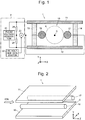
- Fig. 1 is a schematic configuration diagram of an ion separator section in the ion mobility spectrometer of the present embodiment.
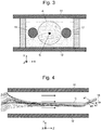
- Fig. 2 is a schematic perspective view of the ion separator section in the ion mobility spectrometer of the same embodiment.
- the ion mobility spectrometer in the present embodiment has a pair of plate electrodes 11 and 12 held by spacers 13 and 14 at a predetermined distance from each other in the Y-axis direction, with an ion separation space 15 formed in between.
- two rod electrodes 16 and 17 are arranged at a certain distance from each other in the X-axis direction, with the central axis C in between.
- These rod electrodes 16 are 17 consist of cylindrical conductors extending in the Z-axis direction.
- the two rod electrodes 16 and 17 are parallel to each other as well as to the plate electrodes 11 and 12.
- the voltage generator 2 includes a pulse voltage generator 21 acting as the main voltage generator, which is also provided in the conventional device, as well as two resistors 24 and 25, a DC voltage generator 22 and a voltage adder 23, which constitute the electric-field correction voltage generator for applying a voltage to the rod electrode 16 and 17.
- the pulse voltage generator 21 applies an asymmetric pulse voltage between the upper and lower plate electrodes 11 and 12. This voltage is similar to the one used in the conventional device, as shown in Fig. 11 .
- a pulse voltage generated by dividing this asymmetric pulse voltage by the serially connected resistors 24 and 25, and the DC voltage with a predetermined voltage value V0 generated by the DC voltage generator 22, are added by the voltage adder 23 and commonly applied to the two rod electrodes 16 and 17.
- the voltage thus applied can also be regarded as a voltage generated by reducing the amplitude (or pulse height, V1-V2) of the asymmetric pulse voltage according to the resistance ratio of the resistors 24 and 25, with its DC voltage level appropriately shifted (i.e. with an offset voltage given) by the predetermined voltage value V0.
- the rise and fall of the pulse voltage applied to the rod electrodes 16 and 17 is synchronized with those of the asymmetric pulse voltage; the voltage value applied to the rod electrodes 16 and 17 alternately changes with the switching of the phase between the period of time T H where the asymmetric pulse voltage is at the high level (VI) and the period of time T L where the asymmetric pulse voltage is at low high level (V2).
- the equipotential surfaces in the electric field created within the ion separation space 15 at one point in time are substantially parallel to the plate electrodes 11 and 12.
- the potential on the outer cylindrical surface of each of the rod electrodes 16 and 17 at one point in time becomes a predetermined potential corresponding to the voltage applied to the plate electrodes 11 and 12 at that point in time. Therefore, this potential on the rod electrodes 16 and 17 determines the shape, density (i.e.
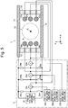
- Fig 3 shows one example of the result of a simulation of the equipotential surfaces formed by an electric field created within the ion separation space 15 at one point in time where the high-level voltage value V1 is applied between the plate electrodes 11 and 12 (actually, those surfaces are drawn by translating equipotential lines on the X-Y plane along the Z-axis).
- the outer circumferential surfaces of the rod electrodes 16 and 17 have a predetermined equal potential. Therefore, the equipotential surfaces in the present example are densely formed in the space between the lower plate electrode 12 and the rod electrodes 16 and 17. In the vicinity of the rod electrodes 16 and 17, those equipotential surfaces are curved along the outer circumferential surfaces of the rod electrodes 16 and 17.
- the equipotential surfaces in the space between the rod electrodes 16 and 17 become curved surfaces bulging upward, as shown in Fig. 3 .
- This shape is analogous to that of the equipotential surfaces formed in the ion separator section which uses the cylindrical electrodes shown in Fig. 13 .
- the shape of the equipotential surfaces changes depending on whether the phase of the asymmetric pulse voltage is within the period of time T H where the voltage is at the high level or within the period of time T L where the voltage is at the low level.
- a force which acts on ions moving in an electric field due to the effect of the same field is substantially orthogonal to the equipotential surfaces. If the equipotential surfaces in the electric field created within the ion separation space 15 are substantially parallel to the plate electrodes 11 and 12, the ions merely experience a vertical-swinging force (in the Y-axis direction in Figs. 1-3 ) every time the electric field is switched between the high and low levels according to the applied asymmetric pulse voltage; there is no force causing the ions to converge onto a specific position or region. Therefore, the spatial spread of the ions observed at their incidence into the ion separation space 15 does not decrease even after they pass through the ion separation space 15. On the contrary, ions which have the same mobility ratio and yet are varied in energy and/or incident angle will have their trajectories spread while they pass through the ion separation space 15.
- ions located in the vicinity of the rod electrodes 16 and 17 experience a force which causes the ions to come closer to the Y-Z plane passing through the central axis C, although the positive/negative direction for the movement of the ions in the Y-axis direction is reversed.
- the spread of the ions carried by the flow of the buffer gas through the ion separation space 15 is reduced in both width (X-axis) and height (Y-axis) directions, and the ions converge into the vicinity of the Y-Z plane passing through the central axis C while being gradually separated according to their mobility ratios.
- Fig. 4 is a diagram showing the result of a simulation of the ion trajectories in the ion separation space 15.
- the conditions of this trajectory simulation were set so as to simulate three kinds of ions having different mobility ratios incident on the almost entire area of the ion separation space 15 between the plate electrodes 11 and 12.
- the voltages applied to the plate electrodes 11 and 12 as well as the rod electrodes 16 and 17 were set so that an almost highest ion-separation performance would be achieved.
- the three kinds of ions having different mobility ratios gradually converge into a central region, being separated into laminar forms in the Y-axis direction.
- each ion stream is also sufficiently converged in the X-axis direction.
- two extremely thin electrode plates 18 and 19 are arranged outside the exit end plane of the ion separation space 15 so as to separate the three layers of the ion paths.
- a predetermined voltage having the same polarity as the ions is applied to these electrode plates 18 and 19. Due to this voltage, the ion stream following the path a1 passing through the space above the electrode plate 18 is slightly deflected upward, while the ion stream following the path a3 passing through the space below the electrode plate 19 is slightly deflected downward.
- the three ion streams following the paths a1, a2 and a3 are further separated from each other. This facilitates the detection or collection of each kind of ions separated by mobility ratio.
- Figs. 7-9 are schematic configuration diagrams showing some modes of the ion mobility spectrometer using the ion separator section 1 configured in the previously described manner.
- ions or electrically charged aerosol or the like
- a detector 31 which has an extremely small detection surface, or which collects and detects only ions arriving at an extremely small area, is placed at a predetermined position outside the exit end plane of the ion separation space 15. This detector 31 receives only an ion stream forming one separate laminar flow which contains ions having one specific mobility ratio; ion streams which contain ions having other mobility ratios do not enter the detector 31.
- the present ion mobility spectrometer can selectively detect ions having a specific mobility ratio.
- the mobility ratio of the ions to be detected can be changed by controlling the value of the DC voltage generated from the DC voltage generator 22 so as to change the positions at which the ion streams separated into the laminar forms arrive, or by mechanically changing the placement position of the detector 31.
- the rear-edge ends of the rod electrodes 16 and 17 extend beyond those of the plate electrodes 11 and 12. Since the rod electrodes 16 and 17 extend in the same direction as the flow direction of the buffer gas (Z-axis direction) within the ion separation space 15, the rear-edge end portions of the rod electrodes 16 and 17 protruding from the exit end plane of the ion separation space 15 in the aforementioned manner have the effect of reducing the turbulence of the buffer gas flowing out of the exit end plane of the ion separation space 15, i.e. they straighten the buffer-gas flow. This prevents the ion streams separated into laminar forms according to their mobility ratios from being mixed with each other due to turbulence of the buffer-gas flow immediately after leaving the exit end plane of the ion separation space 15.
- a plurality of detectors 31a, 31b and 31c (in the present example, three detectors) each of which has an extremely small detection surface, or each of which collects and detects only ions arriving at an extremely small area, are arranged in the Y-axis direction at a predetermined position outside the exit end plane of the ion separation space 15.
- Each of the detectors 31a, 31b and 31c receives only an ion stream forming one separate laminar flow which contains ions having one specific mobility ratio. Accordingly, the present ion mobility spectrometer can concurrently detect three kinds of ions having specific mobility ratios which differ from each other.
- the present ion mobility spectrometer may also be configured so that the position of each of the plurality of detectors 31a, 31b and 31 can be independently changed, or so that the plurality of detectors 31a, 31b and 31 are combined as one integrated unit whose position can be changed.
- a two-dimensional detector 32 as the position-sensitive detector is provided outside the exit end plane of the ion separation space 15.
- One example of the two-dimensional detector 32 is the combination of a microchannel plate (MCP) for converting ions into electrons, a fluorescent screen for converting electrons into photons, and a two-dimensional image sensor including a large number of micro-sized photodetector elements for converting light into electric signals.
- MCP microchannel plate
- the positions at which the ion streams separated into laminar forms according to their mobility ratios have arrived can be obtained as the address information on the two-dimensional detector 32. Therefore, signal intensities which respectively correspond to a plurality of ion streams can be individually obtained.
- a detector is used to detect ions separated according to their mobility ratios in the ion separator section 1.
- an ion introduction element such as a skimmer or aperture plate, may be provided to extract an ion stream containing ions having one or more predetermined mobility ratios through the ion introduction element, and introduce the extracted ions into a mass analyzer, such as a quadrupole mass filter.
- a mass analyzer such as a quadrupole mass filter.
- ion mobility spectrometers in the previous embodiment are provided with only two rod electrodes 16 and 17 within the space between the pair of plate electrodes 11 and 12, with a stream of buffer gas passed through the space between the two rod electrodes 16 and 17 to carry the ions. It is also possible to provide a greater number of rod electrodes parallel to each other and utilize all spaces formed between the neighboring rod electrodes.
- Fig. 5 shows a schematic perspective view of the ion separator section 1 in an ion mobility spectrometer according to another embodiment of the present invention in which such a structure is adopted.
- five rod electrodes 16A, 17A, 16B, 17B and 16C are arranged within the space between a pair of plate electrodes 11A and 12A which are considerably wide in the X-axis direction.
- the four spaces formed between the neighboring rod electrodes are used for the conveyance and separation of the ions. Since the same voltage is commonly applied to the five rod electrodes 16A, 17A, 16B, 17B and 16C, the same ion-separating condition is created in any of those four spaces, so that ion streams separated into laminar forms according to their mobility ratios are obtained within each of those spaces. Thus, a large amount of ions can be concurrently separated.
- Fig. 4 is a schematic configuration diagram of the ion separator section in an ion mobility spectrometer in another embodiment of the present invention in which yet another structure is adopted.
- a plurality of pairs (in the present example, three pairs) of rod electrodes separated from each other in the Y-axis direction are placed between the pair of plate electrodes 11 and 12, i.e. the first pair of rod electrodes 16a and 17a, second pair of rod electrodes 16b and 17b, as well as third pair of rod electrodes 16c and 17c.
- the voltage generator 2 is provided with: a first electric-field correction voltage generator which includes two resistors 24a and 25a, a DC voltage generator 22a and a voltage adder 23a; a second electric-field correction voltage generator which includes two resistors 24b and 25b, a DC voltage generator 22b and a voltage adder 23b; and a third electric-field correction voltage generator which includes two resistors 24c and 25c, a DC voltage generator 22c and a voltage adder 23c.
- the amplitude of the asymmetric pulse voltage applied to each rod electrode can be controlled as needed by appropriately adjusting the resistance ratio of the two resistors (24a and 25a, 24b and 25b, or 24c and 25c) serially connected in each of the first through third electric-field correction voltage generators.
- the offset of the voltage applied to each rod electrode can also be controlled by appropriately adjusting the voltage value of the DC voltage generated by the DC voltage generator 22a, 22b or 22c.
- rod electrodes in any of the previous embodiments have a cylindrical shape
- their cross-sectional outer edge does not always need to have a circular shape.
- it may have an elliptical, polygonal, square, or rectangular shape.
- the same voltage is commonly applied to the two or plurality of rod electrodes. It is also possible to intentionally apply a slightly higher DC voltage to one rod electrode than the other one (or ones) so as to make the electric field asymmetric also in the X-axis direction and thereby shift the converging position of the ions in the X-axis direction.
Landscapes
- Physics & Mathematics (AREA)
- Chemical & Material Sciences (AREA)
- Spectroscopy & Molecular Physics (AREA)
- Analytical Chemistry (AREA)
- Health & Medical Sciences (AREA)
- Life Sciences & Earth Sciences (AREA)
- Electrochemistry (AREA)
- Chemical Kinetics & Catalysis (AREA)
- Biochemistry (AREA)
- General Health & Medical Sciences (AREA)
- General Physics & Mathematics (AREA)
- Immunology (AREA)
- Pathology (AREA)
- Molecular Biology (AREA)
- Other Investigation Or Analysis Of Materials By Electrical Means (AREA)
Abstract
Description
- The present invention relates to an ion mobility spectrometer for separating ions by mobility, and more specifically, to a parallel-plate non-uniform electric field ion mobility spectrometer which uses parallel plate electrodes and separates ions by creating a non-uniform electric field between those electrodes and making the ions move through this electric field.
- When a molecular ion generated from a sample molecule is made to move through a gaseous (or liquid) medium by the effect of an electric field, the ion moves at a speed proportional to its mobility which is determined by the strength of the electric field, size of the molecule and other factors. Ion mobility spectrophotometry (IMS) is a measurement technique which utilizes this mobility for an analysis of sample molecules. Commonly known devices include a device in which ions separated according to their mobilities are introduced into and detected by a detector, as well as a device in which ions separated according to their mobilities are introduced into a mass analyzer or similar device to detect each ion after separating them according to their mass-to-charge ratios.
- As one technique for the ion mobility spectrometry, a technique called the "differential mobility spectrometry" (DMS) has conventionally been known (see
Patent Literature 1 and Non Patent Literature 1). Under a strong electric field, the mobility of an ion is no longer proportional to the strength of the electric field, and furthermore, the rate of change in the mobility is different for each ion species. DMS uses this principle to separate different ion species. -
Figs. 10 and 11 are schematic configuration diagrams of anion separator section 1 in a conventional parallel plate electrode differential mobility spectrometer (DMS).Figs. 10 and 11 illustrate theion separator section 1 viewed from different directions. - In this
ion separator section 1, the space sandwiched between upper andlower plate electrodes ion separation space 15 for separating ions. From apulse voltage generator 21, an asymmetric pulse voltage in which, as shown inFig. 12 , the period of time TH where the voltage value is at the high level (VI) is significantly different the period of time TL where the voltage value is at the low level (V2), is applied between theplate electrodes spacers ion separation space 15. - During the period of time TH where the applied voltage is at the high level, a high electric field having a relatively high field strength EH is formed within the
ion separation space 15. During the period of time TL where the applied voltage is at the low level, a low electric field having a relatively low field strength EL is formed within theion separation space 15. Now, consider the case where three kinds of ions with different mobilities are injected into theion separation space 15 at a predetermined speed in the Z-axis direction, as shown inFig. 10 . - While the ions are moving forward, the strength of the electric field within the
ion separation space 15 alternates between EH and EL. Consequently, the ions travelling through theion separation space 15 alternately experience a force due to the high electric field with field strength EH and a force due to the low electric field with field strength EL. For the ions travelling through theion separation space 15, this situation can be regarded as the presence of a highelectric field region 100 with field strength EH and a lowelectric field region 101 with field strength EL alternately arranged along the Z axis, as shown inFig. 10 . The ratio of the length of the highelectric field region 100 to that of the lowelectric field region 101 in the Z-axis direction is determined by the ratio of the high-level-voltage period TH to the low-level-voltage period TL. - When the ions pass through the high
electric field region 100, the three kinds of ions all move closer to theupper plate electrode 11 due to the force from this electric field. In this phase, the three ions, whose mobilities within the highelectric field region 100 are µH1, µH2 and µH3, have speeds of EH•µH1, EH•µH2 and EH•µH3, respectively. By comparison, when the ions pass through the lowelectric field region 101, the three kinds of ions all move closer to thelower plate electrode 12 due to the force from this electric field. In this phase, the three ions, whose mobilities within the lowelectric field region 101 are µL1, µL2 and µL3, have speeds of EL•µL1, EL•µL2 and EL•µL3, respectively. Consequently, each of the three ions moves in zigzags within theion separation space 15. - For one kind of ion for which the ratio of the mobility within the high
electric field region 100 to the mobility within the lowelectric field region 101 is α1=µH1/µL1 (which is hereinafter simply called the "mobility ratio"), if the separation condition is determined so as to satisfy TH•EH•µH1=TL•EL•µL1, the amount of movement of this ion species in the Y-axis direction within the highelectric field region 100 equals that of the movement in the Y-axis direction (in the negative direction) within the lowelectric field region 101. Therefore, this ion species moves in zigzags along the central axis C while being carried by the buffer-gas flow, to eventually reach the exit end of theion separation space 15. The path of this ion species is schematically indicated by line "a" inFig. 10 . - For the other two ion species whose mobility ratios are different from α1, i.e. α2=µH2/µL2 and α3=µH3/µL3, the amount of movement in the Y-axis direction within the high
electric field region 100 is not equal to that of the movement in the Y-axis direction within the lowelectric field region 101. Therefore, as they move forward within theion separation space 15, those ions gradually deviate from the central axis C (see trajectories "b" and "c" inFig. 10 ). Upon reaching a sufficiently large distance from the central axis C, the ions come in contact with theplate electrode - In the previously described parallel-plate electrode DMS, the ions passing through the
ion separation space 15 experience the force due to the electric field only in the Y-axis direction (positive or negative). Accordingly, if an ion having the mobility ratio of α1 is incident on a point displaced from the central axis C on the entrance end plane (which is an end plane parallel to the X-Y plane) of theion separation space 15, this ion will exit from theion separation space 15 at a point displaced from the central axis C on the exit end plane of the same space. This means that, if a group of ions having the same mobility ratio are spatially spread when they are introduced into theion separation space 15, those ions will remain spatially spread even when they exit from theion separation space 15. Furthermore, even a group of ions having the same mobility ratio and incident on the same point on the entrance end plane of theion separation space 15 do not always follow the path "a" along the central axis C, since they vary in the amount of initial energy, incident angle and other relevant quantities. Therefore, ions having one mobility ratio are typically spread over a wide area, e.g. as indicated by "A" inFig. 11 , when they arrive at the exit end plane of theion separation space 15. - Such a spatial spread of the ions having the same mobility ratio lowers the transmission efficiency of the ions when the ions arriving at a specific position are to be extracted through an aperture plate, skimmer or similar device placed outside the exit end of the
ion separation space 15. Consequently, it will be difficult to improve the measurement sensitivity. Furthermore, when a plurality of ion species having different mobility ratios are to be separated from each other and individually extracted, it is likely that other ion species will be mixed with the intended one and consequently lower the measurement accuracy. - As an improved version of the DMS, a device using cylindrical electrodes as shown in
Fig. 13 has also been commonly known (see Non Patent Literature 2). In this DMS, as in the aforementioned example, an asymmetric pulse voltage is applied between the concentrically arrangedcylindrical electrodes ion separation space 15 between thosecylindrical electrodes cylindrical electrodes cylindrical electrode 120. Therefore, a force which reduces the spatial spread of the ions travelling through theion separation space 15 acts on those ions, making them converge on an arc-shaped specific center line B. - However, even such a DMS cannot produce a significant ion-converging effect in the lateral direction of the ion stream, and therefore, is not sufficiently effective for improving the ion transmission efficiency. Furthermore, producing the cylindrical electrodes with a high level of mechanical precision incurs a considerably high amount of cost as compared to the parallel-plate electrodes. Accordingly, a configuration as shown in
Fig. 13 is unfavorable in terms of the device cost. - Patent Literature 1:
US 6774360 B -
- Non Patent Literature 1: "1-8-4-1 Shitsuryou Bunseki Kanren Kiki/Haifuneeteddo Gijutsu/Ion Idoudo Sokutei/Ion Idoudo-kei (IMS), 1-8-4-1-2 High-Field Asymmetric Waveform Ion Mobility Spectrometry-Mass Spectrometry (FAIMS-MS) [1-8-4-1 Mass spectrometric Devices/Hyphenated Techniques/Ion Mobility Measurement/Ion Mobility Spectrometer (IMS), 1-8-4-1-2 High-Field Asymmetric Waveform Ion Mobility Spectrometry-Mass Spectrometry (FAIMS-MS)]", Japan Patent Office, [accessed on July 1, 2014], the Internet <URL: http://www.jpo.go.jp/shiryou/s_sonota/hyoujun_gijutsu/mass/1-8-4.pdf>
- Non Patent Literature 2: G. A. Eiceman and two other authors, "Ion Mobility Spectrometry", CRC Press, 2013
- The present invention has been developed to solve the previously described problem. Its primary objective is to provide a parallel-plate non-uniform electric field ion mobility spectrometer which uses parallel-plate electrodes for creating a non-uniform electric field and yet is capable of achieving a high level of ion transmission efficiency as well as a high level of ion separation performance.
- The present invention developed for solving the previously described problem is a parallel-plate non-uniform electric field ion mobility spectrometer including a pair of parallel plate electrodes and a main voltage generator for applying an asymmetric pulse voltage to the plate electrodes so as to create a non-uniform electric field within an ion separation space between the plate electrodes, for separating ions according to mobility by introducing ions derived from a sample component into the ion separation space while a flow of buffer gas is passed through the ion separation space at a constant flow velocity in the same direction as the direction in which the ions are introduced, and by controlling the movement of the ions by an effect of the non-uniform electric field while the ions are carried by the flow of buffer gas, the ion mobility spectrometer including:
- a) at least two electric-field correction electrodes located within the ion separation space sandwiched between the plate electrodes, the electric-field correction electrodes shaped like rods extending in the same direction as the passing direction of the ions and facing each other across an area where the ions pass through; and
- b) an electric-field correction voltage generator for applying, to the electric-field correction electrodes, a voltage obtained by adding a predetermined DC voltage and a pulse voltage synchronized with the asymmetric pulse voltage.
- The "asymmetric pulse voltage" is a pulse voltage in which the period of time where the voltage value is at the high level is not equal to the period of time where the voltage value is at the low level, i.e. a pulse voltage whose duty cycle is not 0.5 (50 %).
- In the ion mobility spectrophotometer according to the present invention, the electric field created within the ion separation space sandwiched between the pair of plate electrodes during the period of time where the high-level voltage in the asymmetric pulse voltage is applied between those plate electrodes is different from the electric field created during the period of time where the low-level voltage is applied. If the electric-field correction electrodes are not present within the ion separation space, the equipotential surfaces in the electric field created within the ion separation space become substantially parallel to the plate electrodes. Ions moving through this electric field experience a force in a direction substantially orthogonal to those equipotential surfaces. Therefore, no ion-converging force acts on the ions if the equipotential surfaces are substantially parallel to the plate electrodes as just mentioned.
- By comparison, in the ion mobility spectrometer according to the present invention, the potential at the (spatial) position where an electric-field correction electrode is placed within the ion separation space is determined by the voltage applied from the electric-field correction voltage generator to the electric-field correction electrode concerned. The spacing and shape of the equipotential surfaces in the electric field created within the space between the electric-field correction electrode and each of the plate electrodes facing each other across that correction electrode are dependent on the shape and size of the electric-field correction electrode, or on its position and the applied voltage. Therefore, by appropriately determining the shape, size and other parameters concerning the electric-field correction electrodes as well as appropriately setting the applied voltage, the equipotential surfaces in the electric field created within the space sandwiched between the electric-field correction electrodes in the ion separation space are deformed into curved surfaces, causing an ion-converging force to act on ions which move within the electric field. While being affected by this force, each ion moves in zigzags according to its mobility ratio due to the effect of the asymmetric pulse voltage. As a result, an ion stream which is converged to a certain degree is obtained for each mobility ratio at the exit end of the ion separation space. Therefore, for example, by placing a skimmer or similar device at the position where the ion stream showing the mobility ratio of interest arrives, that ion of interest can be extracted with high efficiency.
- In the parallel-plate non-uniform electric field ion mobility spectrometer according to the present invention, the electric-field correction voltage generator needs to apply, to the electric-field correction electrodes, a pulse voltage which is synchronized with the asymmetric pulse voltage applied to the plate electrodes and whose DC voltage level is appropriately adjusted.
- Accordingly, in the parallel-plate non-uniform electric field ion mobility spectrometer according to the present invention, the electric-field correction voltage generator may preferably be configured to add the predetermined DC voltage and a pulse voltage generated from the asymmetric pulse voltage by resistive division.
- This configuration allows the amplitude of the pulse voltage applied to the electric-field correction electrodes to be determined by merely adjusting the resistance values for the resistive division.
- In the parallel-plate non-uniform electric field ion mobility spectrometer according to the present invention, there is no specific limitation on the cross-sectional outer-edge shape of the electric-field correction electrodes. For example, the cross-sectional outer-edge shape may be selected from circular, elliptical, polygonal, square and rectangular shapes. The cross-sectional outer-edge does not need to be entirely the aforementioned shape; the minimum requirement is that the cross-sectional outer-edge shape should have a circular shape, elliptical shape or any one of the aforementioned shapes at least on the side facing the central axis, i.e. on the side facing the space where ions pass through.
- Under typical conditions, the length of the electric-field correction electrodes only needs to be roughly equal to the length of the pair of plate electrodes in the ion-passage direction. However, the electric-field correction electrodes may additionally have an extended portion extending beyond the ion exit end of the plate electrodes. The electric-field correction electrodes arranged within the ion separation space normally extend in the same direction as the flow of the ion-carrying buffer gas. This makes the electric-field correction electrodes double as a guide for helping the buffer gas to flow straight. Accordingly, providing the electric-field correction electrodes with the extended portion in the aforementioned manner produces the effect of suppressing turbulence of the flow of the buffer gas in the area outside the ion exit end of the plate electrodes, thereby preventing the ions separated by mobility ratio from being mixed with each other.
- In the parallel-plate non-uniform ion mobility spectrometer according to the present invention, the voltage generator may be configured to apply, to one of the pair of plate electrodes, an additional DC voltage higher than the potential of the other plate electrode, and the electric-field correction voltage generator may be configured to apply, to one of a pair of the electric-field correction electrodes facing each other across an ion stream, an additional DC voltage higher than the potential of the other electric-field correction electrode.
- The amount of each of these additional DC voltages is much smaller than the entire voltage applied the electrode concerned. The application of such additional DC voltages causes a slight imbalance of the electric field, making it possible to slightly shift the positions at which the ion streams which are separately guided according to their mobility ratios arrive.
- As a first mode of the present invention, the parallel-plate non-uniform electric field ion mobility spectrometer may include a single detector having a size that allows selective detection of only one ion stream having a specific mobility ratio among a plurality of ion streams formed by the ions separated by mobility ratio as a result of passing through the ion separation space, the single detector placed at a position at which the ion stream concerned arrives.
- The parallel-plate non-uniform electric field ion mobility spectrometer according to this first mode can selectively detect ions having a specific mobility ratio.
- As a second mode of the present invention, the parallel-plate non-uniform electric field ion mobility spectrometer may include two or more detectors having sizes that allow respective and selective detection of two or more ion streams among a plurality of ion streams formed by the ions separated by mobility ratio as a result of passing through the ion separation space, the two or more detectors placed at positions at which the two or more ion streams respectively arrive.
- The parallel-plate non-uniform electric field ion mobility spectrometer according to this second mode can simultaneously detect two or more kinds of ions having specific mobility ratios which differ from each other.
- As a third mode of the present invention, the parallel-plate non-uniform electric field ion mobility spectrometer may include a single position-sensitive detector placed at positions at which two or more ion streams having specific mobility ratios which differ from each other arrive among a plurality of ion streams formed by the ions separated by mobility ratio as a result of passing through the ion separation space, so as to separately detect each of the two or more ion streams with the position-sensitive detector.
- One example of the position-sensitive detector is a two-dimensional detector having a large number of micro-sized detection elements arrayed in a two-dimensional form. The parallel-plate non-uniform electric field ion mobility spectrometer according to this third mode can also simultaneously detect two or more kinds of ions having specific mobility ratios which differ from each other.
- The parallel-plate non-uniform electric field ion mobility spectrometer according to the present invention minimally requires only two electric-field correction electrodes. It is also possible to arrange three or more electric-field correction electrodes substantially parallel to each other and allow an ion stream to pass through each of the spaces formed between the neighboring electric-field correction electrodes, whereby, for example, a greater amount of ions can be separated according to their mobilities.
- That is to say, the parallel-plate non-uniform electric field ion mobility spectrometer according to the present invention may include three or more of the electric-field correction electrodes arranged parallel to each other within the space between the pair of plate electrodes and spaced in the planer direction of the plate electrodes so that each space formed between the neighboring electric-field correction electrodes serves as the ion separation space.
- In the parallel-plate non-uniform electric field ion mobility spectrometer according to the present invention, two or more groups of the electric-field correction electrodes separated from each other in the direction orthogonal to the plate electrodes may be provided, each group including a plurality of electrodes facing each other across an area where ions pass through, and the electric-field correction voltage generator may be configured to be capable of applying a different voltage for each of the two or more groups of the electric-field correction electrodes.
- This configuration makes it possible to finely tune the electric field distribution within the space between the pair of plate electrodes in the direction orthogonal to the plate electrodes, so as to more properly separate ions.
- The various previously described configurations applied in the case of using a pair of (two) electric-field correction electrodes can also be similarly adopted in the case of using three or more electric-field correction electrodes.
- In the parallel-plate non-uniform electric field ion mobility spectrometer according to the present invention, ions which have been separated according to their mobility ratios can be spatially converged and extracted from the ion separation space by means of a combination of simple-shaped electrodes, such as parallel plate electrodes and rod electrodes. Consequently, a greater amount of ions are supplied for such operations as the detection of ions having a specific mobility ratio or the introduction of ions into a device in the next stage (e.g. mass spectrometer unit), so that the detection sensitivity or measurement sensitivity will be improved.
- Additionally, the parallel-plate non-uniform electric field ion mobility spectrometer according to the present invention provides an improved capability to separate ions according to their mobility ratios, which reduces the mixture of ions having different mobility ratios and consequently improves the detection sensitivity or measurement sensitivity. The present invention is also advantageous in terms of the device cost since the device structure will not become complex.
-
-
Fig. 1 is a schematic configuration diagram of an ion separator section in an ion mobility spectrometer as one embodiment of the present invention. -
Fig. 2 is a schematic perspective view of the ion separator section in the ion mobility spectrometer of the present embodiment. -
Fig. 3 is a diagram showing the result of a simulation of the equipotential surfaces formed by an electric field created within the ion separation space in the ion mobility spectrometer of the present embodiment. -
Fig. 4 is a diagram showing the result of a simulation of the ion trajectories within the ion separation space in the ion mobility spectrometer of the present embodiment. -
Fig. 5 is a schematic configuration diagram of an ion separator section in an ion mobility spectrometer as another embodiment of the present invention. -
Fig. 6 is a schematic perspective view of an ion separator section in an ion mobility spectrometer as still another embodiment of the present invention. -
Fig. 7 is a schematic configuration diagram of one mode of the ion mobility spectrometer according to the present invention. -
Fig. 8 is a schematic configuration diagram of another mode of the ion mobility spectrometer according to the present invention. -
Fig. 9 is a schematic configuration diagram of another mode of the ion mobility spectrometer according to the present invention. -
Fig. 10 is a diagram illustrating the principle of the ion separation in a conventional DMS. -
Fig. 11 is a schematic configuration diagram of the ion separator section in the conventional DMS. -
Fig. 12 is a waveform diagram showing one example of the asymmetric pulse voltage applied to the plate electrodes in the conventional DMS. -
Fig. 13 is a schematic configuration diagram of the ion separator section in another conventional DMS. - An ion mobility spectrometer as one embodiment of the present invention is hereinafter described with reference to the attached drawings.
-
Fig. 1 is a schematic configuration diagram of an ion separator section in the ion mobility spectrometer of the present embodiment.Fig. 2 is a schematic perspective view of the ion separator section in the ion mobility spectrometer of the same embodiment. - Components which are identical or correspond to those used in the conventional ion mobility spectrometer described using
Figs. 10-13 are denoted by the same numerals. - Similarly to the conventional device, the ion mobility spectrometer in the present embodiment has a pair of
plate electrodes spacers ion separation space 15 formed in between. Within thision separation space 15, tworod electrodes rod electrodes 16 are 17 consist of cylindrical conductors extending in the Z-axis direction. The tworod electrodes plate electrodes - The
voltage generator 2 includes apulse voltage generator 21 acting as the main voltage generator, which is also provided in the conventional device, as well as tworesistors DC voltage generator 22 and avoltage adder 23, which constitute the electric-field correction voltage generator for applying a voltage to therod electrode pulse voltage generator 21 applies an asymmetric pulse voltage between the upper andlower plate electrodes Fig. 11 . - A pulse voltage generated by dividing this asymmetric pulse voltage by the serially connected
resistors DC voltage generator 22, are added by thevoltage adder 23 and commonly applied to the tworod electrodes resistors rod electrodes rod electrodes - If there is no
rod electrodes ion separation space 15, i.e. in the case of the configuration as shown inFig. 11 , the equipotential surfaces in the electric field created within theion separation space 15 at one point in time are substantially parallel to theplate electrodes rod electrodes plate electrodes rod electrodes upper plate electrode 11 and therod electrodes lower plate electrode 12 and therod electrodes rod electrodes -
Fig 3 shows one example of the result of a simulation of the equipotential surfaces formed by an electric field created within theion separation space 15 at one point in time where the high-level voltage value V1 is applied between theplate electrodes 11 and 12 (actually, those surfaces are drawn by translating equipotential lines on the X-Y plane along the Z-axis). As noted earlier, the outer circumferential surfaces of therod electrodes lower plate electrode 12 and therod electrodes rod electrodes rod electrodes rod electrodes Fig. 3 . This shape is analogous to that of the equipotential surfaces formed in the ion separator section which uses the cylindrical electrodes shown inFig. 13 . Needless to say, the shape of the equipotential surfaces changes depending on whether the phase of the asymmetric pulse voltage is within the period of time TH where the voltage is at the high level or within the period of time TL where the voltage is at the low level. - A force which acts on ions moving in an electric field due to the effect of the same field is substantially orthogonal to the equipotential surfaces. If the equipotential surfaces in the electric field created within the
ion separation space 15 are substantially parallel to theplate electrodes Figs. 1-3 ) every time the electric field is switched between the high and low levels according to the applied asymmetric pulse voltage; there is no force causing the ions to converge onto a specific position or region. Therefore, the spatial spread of the ions observed at their incidence into theion separation space 15 does not decrease even after they pass through theion separation space 15. On the contrary, ions which have the same mobility ratio and yet are varied in energy and/or incident angle will have their trajectories spread while they pass through theion separation space 15. - By comparison, in the case where the equipotential surfaces in the space surrounded by the
plate electrodes rod electrodes Fig. 3 , ions located in the vicinity of therod electrodes rod electrode Fig. 3 (i.e. which corresponds to the low electric field region) is formed within theion separation space 15, ions located in the vicinity of therod electrodes ion separation space 15 is reduced in both width (X-axis) and height (Y-axis) directions, and the ions converge into the vicinity of the Y-Z plane passing through the central axis C while being gradually separated according to their mobility ratios. -
Fig. 4 is a diagram showing the result of a simulation of the ion trajectories in theion separation space 15. The conditions of this trajectory simulation were set so as to simulate three kinds of ions having different mobility ratios incident on the almost entire area of theion separation space 15 between theplate electrodes plate electrodes rod electrodes Fig. 4 , while being carried through theion separation space 15 by the buffer-gas flow, the three kinds of ions having different mobility ratios gradually converge into a central region, being separated into laminar forms in the Y-axis direction. Eventually, the ions are separated into streams following different paths "a1", "a2" and "a3" according to the ion species, and exit theion separation space 15. Through not evident inFig. 4 , each ion stream is also sufficiently converged in the X-axis direction. - In the example shown in
Fig. 4 , two extremelythin electrode plates ion separation space 15 so as to separate the three layers of the ion paths. A predetermined voltage having the same polarity as the ions is applied to theseelectrode plates electrode plate 18 is slightly deflected upward, while the ion stream following the path a3 passing through the space below theelectrode plate 19 is slightly deflected downward. Thus, the three ion streams following the paths a1, a2 and a3 are further separated from each other. This facilitates the detection or collection of each kind of ions separated by mobility ratio. -
Figs. 7-9 are schematic configuration diagrams showing some modes of the ion mobility spectrometer using theion separator section 1 configured in the previously described manner. - In a mode of the ion mobility spectrometer shown in
Fig. 7 , ions (or electrically charged aerosol or the like) produced in anion source 30 are introduced into theion separation space 15 of theion separator section 1, where the ions having different mobility ratios are separated into laminar forms, as described earlier. Adetector 31 which has an extremely small detection surface, or which collects and detects only ions arriving at an extremely small area, is placed at a predetermined position outside the exit end plane of theion separation space 15. Thisdetector 31 receives only an ion stream forming one separate laminar flow which contains ions having one specific mobility ratio; ion streams which contain ions having other mobility ratios do not enter thedetector 31. Thus, the present ion mobility spectrometer can selectively detect ions having a specific mobility ratio. - The mobility ratio of the ions to be detected can be changed by controlling the value of the DC voltage generated from the
DC voltage generator 22 so as to change the positions at which the ion streams separated into the laminar forms arrive, or by mechanically changing the placement position of thedetector 31. - In the ion mobility spectrometer shown in
Fig. 7 , the rear-edge ends of therod electrodes plate electrodes rod electrodes ion separation space 15, the rear-edge end portions of therod electrodes ion separation space 15 in the aforementioned manner have the effect of reducing the turbulence of the buffer gas flowing out of the exit end plane of theion separation space 15, i.e. they straighten the buffer-gas flow. This prevents the ion streams separated into laminar forms according to their mobility ratios from being mixed with each other due to turbulence of the buffer-gas flow immediately after leaving the exit end plane of theion separation space 15. - In a mode of the ion mobility spectrometer shown in
Fig. 8 , a plurality ofdetectors ion separation space 15. Each of thedetectors detectors detectors - In a mode of the ion mobility spectrometer shown in
Fig. 9 , a two-dimensional detector 32 as the position-sensitive detector is provided outside the exit end plane of theion separation space 15. One example of the two-dimensional detector 32 is the combination of a microchannel plate (MCP) for converting ions into electrons, a fluorescent screen for converting electrons into photons, and a two-dimensional image sensor including a large number of micro-sized photodetector elements for converting light into electric signals. In this ion mobility spectrometer, the positions at which the ion streams separated into laminar forms according to their mobility ratios have arrived can be obtained as the address information on the two-dimensional detector 32. Therefore, signal intensities which respectively correspond to a plurality of ion streams can be individually obtained. - In the ion mobility spectrometers shown in
Figs. 7-9 , a detector is used to detect ions separated according to their mobility ratios in theion separator section 1. In place of the detector, an ion introduction element, such as a skimmer or aperture plate, may be provided to extract an ion stream containing ions having one or more predetermined mobility ratios through the ion introduction element, and introduce the extracted ions into a mass analyzer, such as a quadrupole mass filter. With this system, ions which have been separated according to their mobility ratios can be further separated according to their mass-to-charge ratios and detected. - The ion mobility spectrometers in the previous embodiment are provided with only two
rod electrodes plate electrodes rod electrodes Fig. 5 shows a schematic perspective view of theion separator section 1 in an ion mobility spectrometer according to another embodiment of the present invention in which such a structure is adopted. In this example, fiverod electrodes plate electrodes 11A and 12A which are considerably wide in the X-axis direction. The four spaces formed between the neighboring rod electrodes are used for the conveyance and separation of the ions. Since the same voltage is commonly applied to the fiverod electrodes -
Fig. 4 is a schematic configuration diagram of the ion separator section in an ion mobility spectrometer in another embodiment of the present invention in which yet another structure is adopted. In this example, a plurality of pairs (in the present example, three pairs) of rod electrodes separated from each other in the Y-axis direction are placed between the pair ofplate electrodes rod electrodes rod electrodes rod electrodes voltage generator 2 is provided with: a first electric-field correction voltage generator which includes tworesistors DC voltage generator 22a and avoltage adder 23a; a second electric-field correction voltage generator which includes tworesistors DC voltage generator 22b and avoltage adder 23b; and a third electric-field correction voltage generator which includes tworesistors DC voltage generator 22c and avoltage adder 23c. - In this configuration, the amplitude of the asymmetric pulse voltage applied to each rod electrode can be controlled as needed by appropriately adjusting the resistance ratio of the two resistors (24a and 25a, 24b and 25b, or 24c and 25c) serially connected in each of the first through third electric-field correction voltage generators. The offset of the voltage applied to each rod electrode can also be controlled by appropriately adjusting the voltage value of the DC voltage generated by the
DC voltage generator plate electrodes - Although the rod electrodes in any of the previous embodiments have a cylindrical shape, their cross-sectional outer edge does not always need to have a circular shape. For example, it may have an elliptical, polygonal, square, or rectangular shape.
- In the previous embodiments, the same voltage is commonly applied to the two or plurality of rod electrodes. It is also possible to intentionally apply a slightly higher DC voltage to one rod electrode than the other one (or ones) so as to make the electric field asymmetric also in the X-axis direction and thereby shift the converging position of the ions in the X-axis direction.
- It should also be noted that any change, modification or addition appropriately made within the spirit of the present invention in any aspect other than the previously described ones will naturally fall within the scope of claims of the present application.
-
- 1... Ion Separator Section
- 11... Upper Plate Electrode
- 12... Lower Plate Electrode
- 13, 14... Spacer
- 15... Ion Separation Space
- 16, 17... Rod Electrode
- 18, 19... Electrode Plate
- 2... Voltage Generator
- 21... Pulse Voltage Generator
- 22, 22a, 22b, 22c... DC Voltage Generator
- 23, 23a, 23b, 23c... Voltage Adder
- 24, 25, 24a, 24b, 24c, 25a, 25b, 25c... Resistor
- C... Central Axis
Claims (10)
- A parallel-plate non-uniform electric field ion mobility spectrometer including a pair of parallel plate electrodes and a main voltage generator for applying an asymmetric pulse voltage to the plate electrodes so as to create a non-uniform electric field within an ion separation space between the plate electrodes, for separating ions according to mobility by introducing ions derived from a sample component into the ion separation space while a flow of buffer gas is passed through the ion separation space at a constant flow velocity in a same direction as a direction in which the ions are introduced, and by controlling a movement of the ions by an effect of the non-uniform electric field while the ions are carried by the flow of buffer gas, the ion mobility spectrometer comprising:a) at least two electric-field correction electrodes located within the ion separation space sandwiched between the plate electrodes, the electric-field correction electrodes shaped like rods extending in a same direction as a passing direction of the ions and facing each other across an area where the ions pass through; andb) an electric-field correction voltage generator for applying, to the electric-field correction electrodes, a voltage obtained by adding a predetermined DC voltage and a pulse voltage synchronized with the asymmetric pulse voltage.
- The parallel-plate non-uniform electric field ion mobility spectrometer according to claim 1, wherein the electric-field correction voltage generator adds the predetermined DC voltage and a pulse voltage generated from the asymmetric pulse voltage by resistive division.
- The parallel-plate non-uniform electric field ion mobility spectrometer according to claim 1 or 2, wherein a cross-sectional outer-edge shape of the electric-field correction electrodes is selected from circular, elliptical, polygonal, square and rectangular shapes.
- The parallel-plate non-uniform electric field ion mobility spectrometer according to one of claims 1-3, wherein the electric-field correction electrodes has an extended portion reaching beyond an ion exit end of the plate electrodes.
- The parallel-plate non-uniform electric field ion mobility spectrometer according to one of claims 1-4, wherein the voltage generator applies, to one of the pair of plate electrodes, an additional DC voltage higher than a potential of the other plate electrode, and the electric-field correction voltage generator applies, to one of a pair of the electric-field correction electrodes facing each other across an ion stream, an additional DC voltage higher than a potential of the other electric-field correction electrode.
- The parallel-plate non-uniform electric field ion mobility spectrometer according to one of claims 1-5, comprising a single detector having a size that allows selective detection of only one ion stream having a specific mobility ratio among a plurality of ion streams formed by the ions separated by mobility ratio as a result of passing through the ion separation space, the single detector placed at a position at which the ion stream concerned arrives.
- The parallel-plate non-uniform electric field ion mobility spectrometer according to one of claims 1-5, comprising two or more detectors having sizes that allow respective and selective detection of two or more ion streams among a plurality of ion streams formed by the ions separated by mobility ratio as a result of passing through the ion separation space, the two or more detectors placed at positions at which the two or more ion streams respectively arrive.
- The parallel-plate non-uniform electric field ion mobility spectrometer according to one of claims 1-5, comprising a single position-sensitive detector placed at positions at which two or more ion streams having specific mobility ratios which differ from each other arrive among a plurality of ion streams formed by the ions separated by mobility ratio as a result of passing through the ion separation space, so as to separately detect each of the two or more ion streams with the position-sensitive detector.
- The parallel-plate non-uniform electric field ion mobility spectrometer according to one of claims 1-8, comprising three or more of the electric-field correction electrodes arranged parallel to each other within a space between the pair of plate electrodes and spaced in a planer direction of the plate electrodes so that each space formed between the neighboring electric-field correction electrodes serves as the ion separation space.
- The parallel-plate non-uniform electric field ion mobility spectrometer according to one of claims 1-9, wherein:two or more groups of the electric-field correction electrodes separated from each other in a direction orthogonal to the plate electrodes are provided, each group including a plurality of electrodes facing each other across an area where ions pass through; andthe electric-field correction voltage generator is capable of applying a different voltage for each of the two or more groups of the electric-field correction electrodes.
Applications Claiming Priority (1)
| Application Number | Priority Date | Filing Date | Title |
|---|---|---|---|
| PCT/JP2015/056814 WO2016143030A1 (en) | 2015-03-09 | 2015-03-09 | Parallel plate-type non-uniform electric field ion mobility spectrometry device |
Publications (3)
| Publication Number | Publication Date |
|---|---|
| EP3270148A4 EP3270148A4 (en) | 2018-01-17 |
| EP3270148A1 true EP3270148A1 (en) | 2018-01-17 |
| EP3270148B1 EP3270148B1 (en) | 2019-11-20 |
Family
ID=56878818
Family Applications (1)
| Application Number | Title | Priority Date | Filing Date |
|---|---|---|---|
| EP15884526.3A Active EP3270148B1 (en) | 2015-03-09 | 2015-03-09 | Parallel plate-type non-uniform electric field ion mobility spectrometry device |
Country Status (5)
| Country | Link |
|---|---|
| US (1) | US10184914B2 (en) |
| EP (1) | EP3270148B1 (en) |
| JP (1) | JP6288367B2 (en) |
| CN (1) | CN107407658B (en) |
| WO (1) | WO2016143030A1 (en) |
Families Citing this family (4)
| Publication number | Priority date | Publication date | Assignee | Title |
|---|---|---|---|---|
| US12204085B2 (en) * | 2018-04-27 | 2025-01-21 | Hewlett-Packard Development Company, L.P. | Nonrotating nonuniform electric field object rotation |
| CN109406914B (en) * | 2018-12-13 | 2024-02-09 | 国网福建省电力有限公司 | Laboratory test device and method for high-voltage electric field environment |
| GB2586786A (en) * | 2019-08-30 | 2021-03-10 | Shimadzu Corp | Device for performing field asymmetric waveform ion mobility spectrometry |
| CN118443772B (en) * | 2024-05-27 | 2026-03-27 | 中国科学院合肥物质科学研究院 | A field-corrected ion mobility spectrometer |
Family Cites Families (10)
| Publication number | Priority date | Publication date | Assignee | Title |
|---|---|---|---|---|
| EP1266395A2 (en) | 2000-03-14 | 2002-12-18 | National Research Council of Canada | Tandem faims/ion-trapping apparatus and method |
| US6956205B2 (en) * | 2001-06-15 | 2005-10-18 | Bruker Daltonics, Inc. | Means and method for guiding ions in a mass spectrometer |
| GB0503010D0 (en) * | 2005-02-14 | 2005-03-16 | Micromass Ltd | Mass spectrometer |
| US8440968B2 (en) * | 2005-02-14 | 2013-05-14 | Micromass Uk Limited | Ion-mobility analyser |
| US7550717B1 (en) | 2006-11-30 | 2009-06-23 | Thermo Finnigan Llc | Quadrupole FAIMS apparatus |
| CN101688848A (en) * | 2007-02-05 | 2010-03-31 | 卓漂仪谱公司 | Ion mobility spectrometer and method |
| US7851745B2 (en) * | 2008-12-12 | 2010-12-14 | Thermo Finnigan Llc | Flat plate FAIMS with lateral ion focusing |
| GB0907619D0 (en) * | 2009-05-01 | 2009-06-10 | Shimadzu Res Lab Europe Ltd | Ion analysis apparatus and method of use |
| CN102954995A (en) * | 2011-08-19 | 2013-03-06 | 中国科学院大连化学物理研究所 | Non-uniform electric field based ion mobility spectrometer |
| WO2014006698A1 (en) * | 2012-07-04 | 2014-01-09 | 株式会社日立製作所 | Ion mobility separation device |
-
2015
- 2015-03-09 JP JP2017504454A patent/JP6288367B2/en active Active
- 2015-03-09 US US15/556,878 patent/US10184914B2/en active Active
- 2015-03-09 WO PCT/JP2015/056814 patent/WO2016143030A1/en not_active Ceased
- 2015-03-09 CN CN201580077621.2A patent/CN107407658B/en active Active
- 2015-03-09 EP EP15884526.3A patent/EP3270148B1/en active Active
Also Published As
| Publication number | Publication date |
|---|---|
| US10184914B2 (en) | 2019-01-22 |
| US20180238831A1 (en) | 2018-08-23 |
| CN107407658B (en) | 2020-08-07 |
| JPWO2016143030A1 (en) | 2017-07-13 |
| EP3270148A4 (en) | 2018-01-17 |
| EP3270148B1 (en) | 2019-11-20 |
| WO2016143030A1 (en) | 2016-09-15 |
| JP6288367B2 (en) | 2018-03-07 |
| CN107407658A (en) | 2017-11-28 |
Similar Documents
| Publication | Publication Date | Title |
|---|---|---|
| CN1829911B (en) | Single device for ion mobility and ion trap mass spectrometry | |
| JP6439080B1 (en) | Method and apparatus for ion mobility separation using alternating current waveform | |
| US8362420B2 (en) | Apparatus and methods for analyzing ions | |
| CA2499471C (en) | High field asymmetric waveform ion mobility spectrometer (faims) | |
| CN109003876B (en) | Ion mobility analyzer and analysis method | |
| US7858934B2 (en) | Quadrupole FAIMS apparatus | |
| US20250076250A1 (en) | Laterally-extended trapped ion mobility spectrometer | |
| EP3270148B1 (en) | Parallel plate-type non-uniform electric field ion mobility spectrometry device | |
| US20130120894A1 (en) | Planar ion funnel | |
| US7851745B2 (en) | Flat plate FAIMS with lateral ion focusing | |
| US20230039701A1 (en) | Charge filter arrangement and applications thereof | |
| US9285343B2 (en) | Multi-dimentional ion mobility separator method and apparatus | |
| CN106066359A (en) | For the method using the extensive stability property component analysis of quadrupole mass filter | |
| US20210048411A1 (en) | Ion mobility spectrometer and method of analyzing ions | |
| US9330896B2 (en) | Mass analysis device and mass separation device | |
| US8952322B2 (en) | FAIMS apparatus and method comprising an ion separation channel of helical shape | |
| US7358504B2 (en) | FAIMS apparatus and method for separating ions | |
| WO2006079096A2 (en) | Ion optics systems | |
| US20260112595A1 (en) | Multi-channel ion router for guiding ions between selectively operated ports | |
| EP1737018A2 (en) | Detecting ions in a spectrometer | |
| CN116829935A (en) | High-pressure ion optics | |
| US7378651B2 (en) | High field asymmetric waveform ion mobility spectrometer FAIMS | |
| WO2011139909A2 (en) | Apparatuses and methods for forming electromagnetic fields | |
| Blase | High resolution ion mobility spectrometry with increased ion transmission: Exploring the analytical utility of periodic-focusing DC ion guide drift cells |
Legal Events
| Date | Code | Title | Description |
|---|---|---|---|
| STAA | Information on the status of an ep patent application or granted ep patent |
Free format text: STATUS: THE INTERNATIONAL PUBLICATION HAS BEEN MADE |
|
| PUAI | Public reference made under article 153(3) epc to a published international application that has entered the european phase |
Free format text: ORIGINAL CODE: 0009012 |
|
| STAA | Information on the status of an ep patent application or granted ep patent |
Free format text: STATUS: REQUEST FOR EXAMINATION WAS MADE |
|
| 17P | Request for examination filed |
Effective date: 20170926 |
|
| A4 | Supplementary search report drawn up and despatched |
Effective date: 20171220 |
|
| AK | Designated contracting states |
Kind code of ref document: A1 Designated state(s): AL AT BE BG CH CY CZ DE DK EE ES FI FR GB GR HR HU IE IS IT LI LT LU LV MC MK MT NL NO PL PT RO RS SE SI SK SM TR |
|
| AX | Request for extension of the european patent |
Extension state: BA ME |
|
| DAV | Request for validation of the european patent (deleted) | ||
| DAX | Request for extension of the european patent (deleted) | ||
| GRAP | Despatch of communication of intention to grant a patent |
Free format text: ORIGINAL CODE: EPIDOSNIGR1 |
|
| STAA | Information on the status of an ep patent application or granted ep patent |
Free format text: STATUS: GRANT OF PATENT IS INTENDED |
|
| RIC1 | Information provided on ipc code assigned before grant |
Ipc: G01N 27/62 20060101AFI20190510BHEP Ipc: H01J 49/06 20060101ALN20190510BHEP |
|
| RIC1 | Information provided on ipc code assigned before grant |
Ipc: G01N 27/62 20060101AFI20190522BHEP Ipc: H01J 49/06 20060101ALN20190522BHEP |
|
| INTG | Intention to grant announced |
Effective date: 20190614 |
|
| GRAS | Grant fee paid |
Free format text: ORIGINAL CODE: EPIDOSNIGR3 |
|
| GRAA | (expected) grant |
Free format text: ORIGINAL CODE: 0009210 |
|
| STAA | Information on the status of an ep patent application or granted ep patent |
Free format text: STATUS: THE PATENT HAS BEEN GRANTED |
|
| AK | Designated contracting states |
Kind code of ref document: B1 Designated state(s): AL AT BE BG CH CY CZ DE DK EE ES FI FR GB GR HR HU IE IS IT LI LT LU LV MC MK MT NL NO PL PT RO RS SE SI SK SM TR |
|
| REG | Reference to a national code |
Ref country code: GB Ref legal event code: FG4D |
|
| REG | Reference to a national code |
Ref country code: CH Ref legal event code: EP |
|
| REG | Reference to a national code |
Ref country code: IE Ref legal event code: FG4D |
|
| REG | Reference to a national code |
Ref country code: DE Ref legal event code: R096 Ref document number: 602015042328 Country of ref document: DE |
|
| REG | Reference to a national code |
Ref country code: AT Ref legal event code: REF Ref document number: 1204754 Country of ref document: AT Kind code of ref document: T Effective date: 20191215 |
|
| REG | Reference to a national code |
Ref country code: NL Ref legal event code: MP Effective date: 20191120 |
|
| REG | Reference to a national code |
Ref country code: LT Ref legal event code: MG4D |
|
| PG25 | Lapsed in a contracting state [announced via postgrant information from national office to epo] |
Ref country code: LV Free format text: LAPSE BECAUSE OF FAILURE TO SUBMIT A TRANSLATION OF THE DESCRIPTION OR TO PAY THE FEE WITHIN THE PRESCRIBED TIME-LIMIT Effective date: 20191120 Ref country code: GR Free format text: LAPSE BECAUSE OF FAILURE TO SUBMIT A TRANSLATION OF THE DESCRIPTION OR TO PAY THE FEE WITHIN THE PRESCRIBED TIME-LIMIT Effective date: 20200221 Ref country code: NO Free format text: LAPSE BECAUSE OF FAILURE TO SUBMIT A TRANSLATION OF THE DESCRIPTION OR TO PAY THE FEE WITHIN THE PRESCRIBED TIME-LIMIT Effective date: 20200220 Ref country code: BG Free format text: LAPSE BECAUSE OF FAILURE TO SUBMIT A TRANSLATION OF THE DESCRIPTION OR TO PAY THE FEE WITHIN THE PRESCRIBED TIME-LIMIT Effective date: 20200220 Ref country code: SE Free format text: LAPSE BECAUSE OF FAILURE TO SUBMIT A TRANSLATION OF THE DESCRIPTION OR TO PAY THE FEE WITHIN THE PRESCRIBED TIME-LIMIT Effective date: 20191120 Ref country code: FI Free format text: LAPSE BECAUSE OF FAILURE TO SUBMIT A TRANSLATION OF THE DESCRIPTION OR TO PAY THE FEE WITHIN THE PRESCRIBED TIME-LIMIT Effective date: 20191120 Ref country code: LT Free format text: LAPSE BECAUSE OF FAILURE TO SUBMIT A TRANSLATION OF THE DESCRIPTION OR TO PAY THE FEE WITHIN THE PRESCRIBED TIME-LIMIT Effective date: 20191120 Ref country code: NL Free format text: LAPSE BECAUSE OF FAILURE TO SUBMIT A TRANSLATION OF THE DESCRIPTION OR TO PAY THE FEE WITHIN THE PRESCRIBED TIME-LIMIT Effective date: 20191120 |
|
| PGFP | Annual fee paid to national office [announced via postgrant information from national office to epo] |
Ref country code: DE Payment date: 20200225 Year of fee payment: 6 Ref country code: GB Payment date: 20200226 Year of fee payment: 6 |
|
| PG25 | Lapsed in a contracting state [announced via postgrant information from national office to epo] |
Ref country code: HR Free format text: LAPSE BECAUSE OF FAILURE TO SUBMIT A TRANSLATION OF THE DESCRIPTION OR TO PAY THE FEE WITHIN THE PRESCRIBED TIME-LIMIT Effective date: 20191120 Ref country code: RS Free format text: LAPSE BECAUSE OF FAILURE TO SUBMIT A TRANSLATION OF THE DESCRIPTION OR TO PAY THE FEE WITHIN THE PRESCRIBED TIME-LIMIT Effective date: 20191120 Ref country code: IS Free format text: LAPSE BECAUSE OF FAILURE TO SUBMIT A TRANSLATION OF THE DESCRIPTION OR TO PAY THE FEE WITHIN THE PRESCRIBED TIME-LIMIT Effective date: 20200320 |
|
| PG25 | Lapsed in a contracting state [announced via postgrant information from national office to epo] |
Ref country code: AL Free format text: LAPSE BECAUSE OF FAILURE TO SUBMIT A TRANSLATION OF THE DESCRIPTION OR TO PAY THE FEE WITHIN THE PRESCRIBED TIME-LIMIT Effective date: 20191120 |
|
| PGFP | Annual fee paid to national office [announced via postgrant information from national office to epo] |
Ref country code: FR Payment date: 20200214 Year of fee payment: 6 |
|
| PG25 | Lapsed in a contracting state [announced via postgrant information from national office to epo] |
Ref country code: CZ Free format text: LAPSE BECAUSE OF FAILURE TO SUBMIT A TRANSLATION OF THE DESCRIPTION OR TO PAY THE FEE WITHIN THE PRESCRIBED TIME-LIMIT Effective date: 20191120 Ref country code: RO Free format text: LAPSE BECAUSE OF FAILURE TO SUBMIT A TRANSLATION OF THE DESCRIPTION OR TO PAY THE FEE WITHIN THE PRESCRIBED TIME-LIMIT Effective date: 20191120 Ref country code: EE Free format text: LAPSE BECAUSE OF FAILURE TO SUBMIT A TRANSLATION OF THE DESCRIPTION OR TO PAY THE FEE WITHIN THE PRESCRIBED TIME-LIMIT Effective date: 20191120 Ref country code: PT Free format text: LAPSE BECAUSE OF FAILURE TO SUBMIT A TRANSLATION OF THE DESCRIPTION OR TO PAY THE FEE WITHIN THE PRESCRIBED TIME-LIMIT Effective date: 20200412 Ref country code: DK Free format text: LAPSE BECAUSE OF FAILURE TO SUBMIT A TRANSLATION OF THE DESCRIPTION OR TO PAY THE FEE WITHIN THE PRESCRIBED TIME-LIMIT Effective date: 20191120 Ref country code: ES Free format text: LAPSE BECAUSE OF FAILURE TO SUBMIT A TRANSLATION OF THE DESCRIPTION OR TO PAY THE FEE WITHIN THE PRESCRIBED TIME-LIMIT Effective date: 20191120 |
|
| REG | Reference to a national code |
Ref country code: AT Ref legal event code: MK05 Ref document number: 1204754 Country of ref document: AT Kind code of ref document: T Effective date: 20191120 |
|
| REG | Reference to a national code |
Ref country code: DE Ref legal event code: R097 Ref document number: 602015042328 Country of ref document: DE |
|
| PG25 | Lapsed in a contracting state [announced via postgrant information from national office to epo] |
Ref country code: SK Free format text: LAPSE BECAUSE OF FAILURE TO SUBMIT A TRANSLATION OF THE DESCRIPTION OR TO PAY THE FEE WITHIN THE PRESCRIBED TIME-LIMIT Effective date: 20191120 Ref country code: SM Free format text: LAPSE BECAUSE OF FAILURE TO SUBMIT A TRANSLATION OF THE DESCRIPTION OR TO PAY THE FEE WITHIN THE PRESCRIBED TIME-LIMIT Effective date: 20191120 |
|
| PLBE | No opposition filed within time limit |
Free format text: ORIGINAL CODE: 0009261 |
|
| STAA | Information on the status of an ep patent application or granted ep patent |
Free format text: STATUS: NO OPPOSITION FILED WITHIN TIME LIMIT |
|
| 26N | No opposition filed |
Effective date: 20200821 |
|
| PG25 | Lapsed in a contracting state [announced via postgrant information from national office to epo] |
Ref country code: MC Free format text: LAPSE BECAUSE OF FAILURE TO SUBMIT A TRANSLATION OF THE DESCRIPTION OR TO PAY THE FEE WITHIN THE PRESCRIBED TIME-LIMIT Effective date: 20191120 |
|
| REG | Reference to a national code |
Ref country code: CH Ref legal event code: PL |
|
| PG25 | Lapsed in a contracting state [announced via postgrant information from national office to epo] |
Ref country code: AT Free format text: LAPSE BECAUSE OF FAILURE TO SUBMIT A TRANSLATION OF THE DESCRIPTION OR TO PAY THE FEE WITHIN THE PRESCRIBED TIME-LIMIT Effective date: 20191120 Ref country code: PL Free format text: LAPSE BECAUSE OF FAILURE TO SUBMIT A TRANSLATION OF THE DESCRIPTION OR TO PAY THE FEE WITHIN THE PRESCRIBED TIME-LIMIT Effective date: 20191120 Ref country code: SI Free format text: LAPSE BECAUSE OF FAILURE TO SUBMIT A TRANSLATION OF THE DESCRIPTION OR TO PAY THE FEE WITHIN THE PRESCRIBED TIME-LIMIT Effective date: 20191120 |
|
| REG | Reference to a national code |
Ref country code: BE Ref legal event code: MM Effective date: 20200331 |
|
| PG25 | Lapsed in a contracting state [announced via postgrant information from national office to epo] |
Ref country code: LU Free format text: LAPSE BECAUSE OF NON-PAYMENT OF DUE FEES Effective date: 20200309 |
|
| PG25 | Lapsed in a contracting state [announced via postgrant information from national office to epo] |
Ref country code: IE Free format text: LAPSE BECAUSE OF NON-PAYMENT OF DUE FEES Effective date: 20200309 Ref country code: IT Free format text: LAPSE BECAUSE OF FAILURE TO SUBMIT A TRANSLATION OF THE DESCRIPTION OR TO PAY THE FEE WITHIN THE PRESCRIBED TIME-LIMIT Effective date: 20191120 Ref country code: CH Free format text: LAPSE BECAUSE OF NON-PAYMENT OF DUE FEES Effective date: 20200331 Ref country code: LI Free format text: LAPSE BECAUSE OF NON-PAYMENT OF DUE FEES Effective date: 20200331 |
|
| PG25 | Lapsed in a contracting state [announced via postgrant information from national office to epo] |
Ref country code: BE Free format text: LAPSE BECAUSE OF NON-PAYMENT OF DUE FEES Effective date: 20200331 |
|
| REG | Reference to a national code |
Ref country code: DE Ref legal event code: R119 Ref document number: 602015042328 Country of ref document: DE |
|
| GBPC | Gb: european patent ceased through non-payment of renewal fee |
Effective date: 20210309 |
|
| PG25 | Lapsed in a contracting state [announced via postgrant information from national office to epo] |
Ref country code: DE Free format text: LAPSE BECAUSE OF NON-PAYMENT OF DUE FEES Effective date: 20211001 Ref country code: GB Free format text: LAPSE BECAUSE OF NON-PAYMENT OF DUE FEES Effective date: 20210309 Ref country code: FR Free format text: LAPSE BECAUSE OF NON-PAYMENT OF DUE FEES Effective date: 20210331 |
|
| PG25 | Lapsed in a contracting state [announced via postgrant information from national office to epo] |
Ref country code: TR Free format text: LAPSE BECAUSE OF FAILURE TO SUBMIT A TRANSLATION OF THE DESCRIPTION OR TO PAY THE FEE WITHIN THE PRESCRIBED TIME-LIMIT Effective date: 20191120 Ref country code: MT Free format text: LAPSE BECAUSE OF FAILURE TO SUBMIT A TRANSLATION OF THE DESCRIPTION OR TO PAY THE FEE WITHIN THE PRESCRIBED TIME-LIMIT Effective date: 20191120 Ref country code: CY Free format text: LAPSE BECAUSE OF FAILURE TO SUBMIT A TRANSLATION OF THE DESCRIPTION OR TO PAY THE FEE WITHIN THE PRESCRIBED TIME-LIMIT Effective date: 20191120 |
|
| PG25 | Lapsed in a contracting state [announced via postgrant information from national office to epo] |
Ref country code: MK Free format text: LAPSE BECAUSE OF FAILURE TO SUBMIT A TRANSLATION OF THE DESCRIPTION OR TO PAY THE FEE WITHIN THE PRESCRIBED TIME-LIMIT Effective date: 20191120 |