EP3270132B1 - Mems pressure sensor and method for positioning same - Google Patents
Mems pressure sensor and method for positioning same Download PDFInfo
- Publication number
- EP3270132B1 EP3270132B1 EP15885595.7A EP15885595A EP3270132B1 EP 3270132 B1 EP3270132 B1 EP 3270132B1 EP 15885595 A EP15885595 A EP 15885595A EP 3270132 B1 EP3270132 B1 EP 3270132B1
- Authority
- EP
- European Patent Office
- Prior art keywords
- space
- pressure
- mems
- pressure sensor
- mems pressure
- Prior art date
- Legal status (The legal status is an assumption and is not a legal conclusion. Google has not performed a legal analysis and makes no representation as to the accuracy of the status listed.)
- Active
Links
- 238000000034 method Methods 0.000 title claims description 12
- 238000005259 measurement Methods 0.000 claims description 52
- 238000001514 detection method Methods 0.000 claims description 26
- 230000035485 pulse pressure Effects 0.000 claims description 22
- 210000004204 blood vessel Anatomy 0.000 claims description 20
- 239000000853 adhesive Substances 0.000 claims description 2
- 230000001070 adhesive effect Effects 0.000 claims description 2
- 210000002321 radial artery Anatomy 0.000 description 27
- 230000036772 blood pressure Effects 0.000 description 15
- 210000000707 wrist Anatomy 0.000 description 10
- 239000000758 substrate Substances 0.000 description 8
- 238000009530 blood pressure measurement Methods 0.000 description 7
- 238000012545 processing Methods 0.000 description 5
- 239000012528 membrane Substances 0.000 description 3
- 230000003287 optical effect Effects 0.000 description 3
- 229910000679 solder Inorganic materials 0.000 description 3
- 241001465754 Metazoa Species 0.000 description 2
- 238000010586 diagram Methods 0.000 description 2
- 230000010349 pulsation Effects 0.000 description 2
- 239000000523 sample Substances 0.000 description 2
- 239000004593 Epoxy Substances 0.000 description 1
- 230000004872 arterial blood pressure Effects 0.000 description 1
- 239000012620 biological material Substances 0.000 description 1
- 238000012937 correction Methods 0.000 description 1
- 230000001419 dependent effect Effects 0.000 description 1
- 238000013461 design Methods 0.000 description 1
- 230000000694 effects Effects 0.000 description 1
- 239000011521 glass Substances 0.000 description 1
- 239000004973 liquid crystal related substance Substances 0.000 description 1
- 238000000691 measurement method Methods 0.000 description 1
- 239000004065 semiconductor Substances 0.000 description 1
- 239000000126 substance Substances 0.000 description 1
Images


Classifications
-
- A—HUMAN NECESSITIES
- A61—MEDICAL OR VETERINARY SCIENCE; HYGIENE
- A61B—DIAGNOSIS; SURGERY; IDENTIFICATION
- A61B5/00—Measuring for diagnostic purposes; Identification of persons
- A61B5/02—Detecting, measuring or recording pulse, heart rate, blood pressure or blood flow; Combined pulse/heart-rate/blood pressure determination; Evaluating a cardiovascular condition not otherwise provided for, e.g. using combinations of techniques provided for in this group with electrocardiography or electroauscultation; Heart catheters for measuring blood pressure
- A61B5/021—Measuring pressure in heart or blood vessels
- A61B5/02108—Measuring pressure in heart or blood vessels from analysis of pulse wave characteristics
-
- A—HUMAN NECESSITIES
- A61—MEDICAL OR VETERINARY SCIENCE; HYGIENE
- A61B—DIAGNOSIS; SURGERY; IDENTIFICATION
- A61B5/00—Measuring for diagnostic purposes; Identification of persons
- A61B5/68—Arrangements of detecting, measuring or recording means, e.g. sensors, in relation to patient
- A61B5/6801—Arrangements of detecting, measuring or recording means, e.g. sensors, in relation to patient specially adapted to be attached to or worn on the body surface
- A61B5/683—Means for maintaining contact with the body
- A61B5/6832—Means for maintaining contact with the body using adhesives
- A61B5/6833—Adhesive patches
-
- A—HUMAN NECESSITIES
- A61—MEDICAL OR VETERINARY SCIENCE; HYGIENE
- A61B—DIAGNOSIS; SURGERY; IDENTIFICATION
- A61B5/00—Measuring for diagnostic purposes; Identification of persons
- A61B5/02—Detecting, measuring or recording pulse, heart rate, blood pressure or blood flow; Combined pulse/heart-rate/blood pressure determination; Evaluating a cardiovascular condition not otherwise provided for, e.g. using combinations of techniques provided for in this group with electrocardiography or electroauscultation; Heart catheters for measuring blood pressure
- A61B5/021—Measuring pressure in heart or blood vessels
- A61B5/022—Measuring pressure in heart or blood vessels by applying pressure to close blood vessels, e.g. against the skin; Ophthalmodynamometers
-
- A—HUMAN NECESSITIES
- A61—MEDICAL OR VETERINARY SCIENCE; HYGIENE
- A61B—DIAGNOSIS; SURGERY; IDENTIFICATION
- A61B5/00—Measuring for diagnostic purposes; Identification of persons
- A61B5/02—Detecting, measuring or recording pulse, heart rate, blood pressure or blood flow; Combined pulse/heart-rate/blood pressure determination; Evaluating a cardiovascular condition not otherwise provided for, e.g. using combinations of techniques provided for in this group with electrocardiography or electroauscultation; Heart catheters for measuring blood pressure
- A61B5/024—Detecting, measuring or recording pulse rate or heart rate
- A61B5/02444—Details of sensor
-
- A—HUMAN NECESSITIES
- A61—MEDICAL OR VETERINARY SCIENCE; HYGIENE
- A61B—DIAGNOSIS; SURGERY; IDENTIFICATION
- A61B5/00—Measuring for diagnostic purposes; Identification of persons
- A61B5/68—Arrangements of detecting, measuring or recording means, e.g. sensors, in relation to patient
- A61B5/6801—Arrangements of detecting, measuring or recording means, e.g. sensors, in relation to patient specially adapted to be attached to or worn on the body surface
- A61B5/684—Indicating the position of the sensor on the body
-
- G—PHYSICS
- G01—MEASURING; TESTING
- G01L—MEASURING FORCE, STRESS, TORQUE, WORK, MECHANICAL POWER, MECHANICAL EFFICIENCY, OR FLUID PRESSURE
- G01L19/00—Details of, or accessories for, apparatus for measuring steady or quasi-steady pressure of a fluent medium insofar as such details or accessories are not special to particular types of pressure gauges
-
- A—HUMAN NECESSITIES
- A61—MEDICAL OR VETERINARY SCIENCE; HYGIENE
- A61B—DIAGNOSIS; SURGERY; IDENTIFICATION
- A61B2562/00—Details of sensors; Constructional details of sensor housings or probes; Accessories for sensors
- A61B2562/02—Details of sensors specially adapted for in-vivo measurements
- A61B2562/0247—Pressure sensors
-
- A—HUMAN NECESSITIES
- A61—MEDICAL OR VETERINARY SCIENCE; HYGIENE
- A61B—DIAGNOSIS; SURGERY; IDENTIFICATION
- A61B2562/00—Details of sensors; Constructional details of sensor housings or probes; Accessories for sensors
- A61B2562/02—Details of sensors specially adapted for in-vivo measurements
- A61B2562/028—Microscale sensors, e.g. electromechanical sensors [MEMS]
-
- A—HUMAN NECESSITIES
- A61—MEDICAL OR VETERINARY SCIENCE; HYGIENE
- A61B—DIAGNOSIS; SURGERY; IDENTIFICATION
- A61B5/00—Measuring for diagnostic purposes; Identification of persons
- A61B5/68—Arrangements of detecting, measuring or recording means, e.g. sensors, in relation to patient
- A61B5/6801—Arrangements of detecting, measuring or recording means, e.g. sensors, in relation to patient specially adapted to be attached to or worn on the body surface
- A61B5/6813—Specially adapted to be attached to a specific body part
- A61B5/6824—Arm or wrist
-
- A—HUMAN NECESSITIES
- A61—MEDICAL OR VETERINARY SCIENCE; HYGIENE
- A61B—DIAGNOSIS; SURGERY; IDENTIFICATION
- A61B5/00—Measuring for diagnostic purposes; Identification of persons
- A61B5/68—Arrangements of detecting, measuring or recording means, e.g. sensors, in relation to patient
- A61B5/6801—Arrangements of detecting, measuring or recording means, e.g. sensors, in relation to patient specially adapted to be attached to or worn on the body surface
- A61B5/684—Indicating the position of the sensor on the body
- A61B5/6842—Indicating the position of the sensor on the body by marking the skin
Definitions
- the present invention relates to a micro electro mechanical system (hereinafter, referred to as MEMS) pressure sensing apparatus, a pressure measuring system using the same, and a method of positioning an MEMS pressure sensor.
- MEMS micro electro mechanical system
- Patent Document 1 discloses a measuring system, which measures a pulse pressure of, for example, a radial artery part using an optical sensor.
- the invention according to Patent Document 1 is a blood vessel pulse wave measurement system, which performs blood vessel pulse wave measurement using an optical probe circuit provided with an optical probe.
- the blood vessel pulse wave measurement system includes a light emitting element and a light receiving element, where the light emitting element radiates light to a blood vessel through a skin, and the light receiving element receives, through the skin, reflected light from the blood vessel or transmitted light through the blood vessel.
- the blood vessel pulse wave measurement system further includes a drive circuit for driving the light emitting element based on an input drive signal; and a detection circuit for converting the light received by the light receiving element into an electrical signal, and outputting the same signal.
- the blood vessel pulse wave measurement system further includes measurement means, that directly and synchronously feeds back an electrical signal to the drive circuit as a drive signal to generate a self-oscillation signal from the detection circuit, and measures the self-oscillation signal as a blood vessel pulse wave signal.
- the blood vessel pulse wave measurement system further includes control means for controlling an operating point of at least one of the detection circuit and the drive circuit such that the self-oscillation signal substantially reaches a maximum level thereof.
- Fig. 1 is a schematic view showing a configuration example of a pulse wave blood pressure meter system according to a conventional example
- Fig. 1(a) is a vertical sectional view seen from a side of an MEMS pressure sensor 220
- Fig. 1(b) is a bottom view seen from a contact surface in contact with a wrist
- Fig. 2 is a vertical sectional view showing a state of measurement when the MEMS pressure sensor 220 of Fig. 1 is brought into close contact with a radial artery part 7 of a wrist 8 (See, for example, Patent Document 2).
- the MEMS pressure sensor 220 is connected to a pulse wave blood pressure meter main unit 210 via connectors 211a and 21 lb by a cable to measure a blood pressure on a basis of a blood vessel pulse wave signal by a known method.
- a blood pressure of a person under measurement can be measured by bringing the MEMS pressure sensor 220 into close contact with the radial artery part 7 of the wrist 8, and then sensing a pressure variation of a radial arterial pressure detected by the MEMS pressure sensor 220 as a pressure/voltage converted voltage signal so as to be converted into a blood pressure in a manner of making a voltage signal correspond to a standard blood pressure value measured in advance.
- Non-Patent Document 1 Kenichi Yamagoshi and Tatsuo Togawa, "Sensor for Living Body and Measurement Apparatus", edited by Japanese Society for Medical and Biological Engineering/ME Textbook Series, A-I, pp.49 to 50, Corona Publishing Co., Ltd., published on September 25, 2000 .
- An object of the present invention is to solve the foregoing problems and to provide an MEMS pressure sensor and a pressure measuring system using the same, and a method of positioning the MEMS pressure sensor, the MEMS pressure sensor being capable of positioning a sensing portion of the MEMS pressure sensor to, for example, an area of the radial artery part 7 more precisely as compared with the conventional example and being capable of obtaining an S/N ratio higher than that of the conventional example.
- an MEMS pressure sensing apparatus according to independent claim 1.
- Preferred embodiments are defined by dependent claims 2-6.
- the MEMS pressure sensor and the pressure measuring system using the same and the method of positioning the MEMS pressure sensor according to the present invention, it is possible to more precisely position the sensing portion of the MEMS pressure sensor to an area of the radial artery part 7 as compared with a conventional example and to obtain an S/N ratio higher than that of the conventional example.
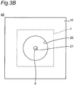
- Fig. 3A is a vertical sectional view showing a configuration of a pressure sensor unit 40 according to a first embodiment and Fig. 3B is a bottom view of the pressure sensor unit 40 in Fig. 3A .
- an MEMS pressure sensor 1 is fixed, by a plurality of solder balls 31, to a center part of a lower side of a square plate-shaped dielectric substrate (may be a semiconductor substrate) 10 with a thickness of t1 and a width of d4 as a dielectric substance made of, for example, glass or epoxy.
- a space 30 is formed to be as large as a thickness of the solder balls 31.
- the MEMS pressure sensor 1 has a square plate-shape with, for example, a width of d3 and has a diaphragm 2 provided in a center part thereof, which is a pressure detection surface 2a having, for example, a round or oval shape.
- the diaphragm 2 On the side of a surface 2b opposed to the pressure detection surface 2a of the diaphragm 2, the above space 30 is formed.
- the diaphragm 2 has a thickness smaller than a thickness t2 of the MEMS pressure sensor 1 in proximity of an upper most part of the MEMS pressure sensor 1, and has a space 21, which is, for example, a tubular or oval tubular hole formed on a lower side of the diaphragm 2.
- the space 21 is sealed against the diaphragm 2 and has a lower side direction opened, so that the space 21 and the space 30 fail to communicate with each other.
- the MEMS pressure sensor 1 which has the space 21 with the height of t2 provided on the side of the pressure detection surface 2a of the diaphragm 2, detects a pressure using the pressure detection surface 2a facing the space 21, and outputs an electrical signal corresponding to the detected pressure via a cable 41 inserted through the dielectric substrate 10.
- a pad 11 with the thickness t3 which is, for example, a double-sided adhesive sheet, is adhered, the pad 11 supporting the MEMS pressure sensor 1 and the dielectric substrate 10.
- support by the pad 11 is realized by a bottom surface 11b of a space in a center part of an upper part thereof with a thickness (t3 to t4) (the center part having a hole of a downward space 22 to be described later).
- the pad 11 has a bottom surface 11a thereof placed on and in contact with a part under measurement which is, for example, a radial artery part 7 of a wrist 8 of a person under measurement (See Fig. 5 ) and has the space 22, which is a through hole communicating with the space 21 in the center part of the pad 11 and having a size in a direction parallel to the pressure detection surface 2a and larger than the space 21.
- the space 21 and the space 22 have bottom surfaces substantially parallel to, for example, the pressure detection surface 2a of the diaphragm 2 and have, for example, substantially tubular or oval tubular shapes coaxial to each other, or polygonal shapes such as a square, rectangular shapes and the like.
- the bottom surface of the space 22 is configured to have a diameter d2 larger than a diameter d 1 of the bottom surface of the space 21.
- pressure sensor unit 40 When thus configured pressure sensor unit 40 is placed on and in contact with, for example, a part under measurement which is the radial artery part 7 of the wrist 8 of a person under measurement (See Fig. 5 ), the space 21 and the space 22 are sealed to be a sealed space, so that a pressure of the part under measurement is transmitted to the diaphragm 2 of the MEMS pressure sensor 1 via the space 21 and the space 22, and the MEMS pressure sensor 1 detects the pressure. A pressure detection signal of the MEMS pressure sensor 1 is outputted via the cable 41.
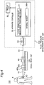
- Fig. 4 is a block diagram showing a configuration of a pulse pressure measuring system 100 using the pressure sensor unit 40 in Fig. 3A .
- the pressure detection signal from the pressure sensor unit 40 is input to a signal amplifier 43 of a signal relay unit 120 via the cable 41, and connectors 42a and 42b, the pressure sensor unit 40 being placed such that the space 22 of the pressure sensor unit 40 is close to, for example, the radial artery part 7 of the person under measurement 6 so as to be able to detect a pressure.
- the signal amplifier 43 amplifies the input pressure detection signal and inputs the amplified signal to an A/D converter 53 of a pulse pressure measurement main unit 110 via a cable 44.
- the pulse pressure measurement main unit 110 is configured with an apparatus controller 50 formed of, for example, a digital computer and having a blood vessel pulse pressure measurement processing module 51 and an internal memory 50m; a display unit 52 such as, for example, a liquid crystal display; and the A/D converter 53.
- the A/D converter 53 outputs the input pressure detection signal to the apparatus controller 50 after A/D converting the same into digital data.
- the apparatus controller 50 By executing processing of the blood vessel pulse pressure measurement processing module 51, the apparatus controller 50 converts the digital data of the pressure detection signal into a pulse pressure value by using a signal level to a pressure value correction table (indicative of a relationship between an electrical signal level of the pressure detection signal and a pressure value) measured and stored in advance in the internal memory 50m, and outputs the obtained value to the display unit 52 to display the same. In this case, the apparatus controller 50 calculates a blood vessel pulse wave signal by executing the above blood vessel pulse pressure measurement processing in real time to display the same on the display unit 52.
- a pressure value correction table indicative of a relationship between an electrical signal level of the pressure detection signal and a pressure value
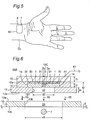
- Fig. 5 is a perspective view showing the pressure sensor unit 40 in Fig. 3A when the pressure sensor unit 40 is attached to the radial artery part 7 of a person under measurement 6. As is clear from Fig. 5 , the pressure sensor unit 40 is attached to the radial artery part 7 of the person under measurement 6 to measure a pulse pressure.
- the inventors have made samples of the pressure sensor unit 40 and the pulse pressure measuring system 100 according to the embodiment A design result was obtained that the diameter d1 of the diaphragm 2 (the space 21) of the MEMS pressure sensor 1 in the pressure sensor unit 40 was most preferably on the order of 1 mm.
- the length d4 of one side of each of the dielectric substrate 10 and the pad 11 was set to be 3 to 4 mm and the diameter d2 of the space 22 was set to be 2 to 3 mm.
- the thickness t2 of the MEMS pressure sensor 1 was 400 ⁇ m and a thickness of a lower portion of the pad 11 was 0.5 to 1 mm.
- a blood vessel needs to be positioned within a range of 1 mm, which is the diameter d1 of the diaphragm 2 of the MEMS pressure sensor 1, and when the position deviates, no pulse pressure can be detected.
- provision of the space 22 enables a pulse pressure to be reliably detected even when the diaphragm 2 of the MEMS pressure sensor 1 deviates on the order of 1 to 1.5 mm as long as the deviation is within a range of the space 22.
- the MEMS pressure sensing apparatus of the present embodiment enables detection of a pulse pressure without applying a pressure, bloodless blood pressure pulse wave measurement can be conducted for a long period of time. Additionally, it is possible, in a manner similar to that of the conventional example, to measure a blood pressure of a person under measurement using the measurement method of Patent Document 2.
- the space 21 and the space 22 are sealed to be a sealed space, so that a pressure of the part under measurement is transmitted to the diaphragm 2 of the MEMS pressure sensor 1 via the space 21 and the space 22, and the MEMS pressure sensor 1 detects the pressure. Accordingly, even when the position of the MEMS pressure sensor 1 deviates from a measurement position, it is possible to precisely measure a pressure of the part under measurement. Additionally, since it is not necessary to apply a pressure to the part under measurement, it is possible to measure, for example, a bloodless blood pressure pulse wave for a long period of time.
- Fig. 6 is a vertical sectional view showing a configuration of a pressure sensor unit 40A according an embodiment of the present invention. Referring to Fig. 6 , the pressure sensor unit 40A according to the second embodiment is different from the pressure sensor unit 40 in Fig. 3A in the following points.
- Step A First of all, the film sheet 13 is adhered to a position of the radial artery part 7 (preferably, a part first confirmed and marked as a position at which pulse can be taken).
- the film sheet 13 is positioned and adhered such that a bonding lower surface 13b of the film sheet 13 is bonded to a surface of skin of the radial artery part 7, and a center part of the pressure sensing cavity hole 13h of the film sheet 13 is located at the radial artery part 7.
- Step B Subsequently, to an upper surface 13a of the film sheet 13, the film sheet 12 of the pressure sensor unit 40A is adhered.
- the pressure sensor unit 40A having the film sheet 12 is positioned such that the mark 10C is located at the center part of the pressure sensing cavity hole 13h, i.e., such that a center part of the pressure sensing cavity hole 12h of the film sheet 12 is located at the center part of the pressure sensing cavity hole 13h.
- Fig. 7 is a vertical sectional view showing the pressure sensor unit 40A in Fig. 6 when the pressure sensor unit 40A is attached to the radial artery part 7 of a person under measurement 6. Specifically, Fig. 7 shows a state after the above Step B.
- a two-stage adhering step enables the sealed spaces 21, 22, and 23 to be reliably formed for sensing pulsation by the MEMS sensor.
- the pressure sensor unit 40A of the second embodiment when the pressure sensor unit 40A is placed on a part under measurement, the spaces 21, 22, and 23 are sealed to be a sealed space, so that a pressure of the part under measurement is transmitted to a diaphragm 2 of an MEMS pressure sensor 1 via the spaces 21, 22, and 23, and the MEMS pressure sensor 1 detects the pressure. Accordingly, even when the position of the MEMS pressure sensor 1 deviates from a measurement position, it is possible to precisely measure the pressure of the part under measurement. Additionally, since it is not necessary to apply a pressure to the part under measurement, it is possible to measure, for example, a bloodless blood pressure pulse wave for a long period of time.
- Fig. 8 is a photograph of signal waveforms of an experimental result obtained when a pulse wave signal of a radial artery part is measured using the MEMS pressure sensor 220 according to the conventional example in Fig. 1 , where Fig. 8(a) shows an output signal waveform of the MEMS pressure sensor 220, and Fig. 8(b) shows a signal waveform obtained when the output signal is passed through a low pass filter.
- Fig. 9 is a photograph of signal waveforms of an experimental result obtained when a pulse wave signal of a radial artery part is measured using the MEMS pressure sensor unit 40A according to the second embodiment in Fig. 6 , where Fig. 9(a) shows an output signal waveform of the MEMS pressure sensor unit 40A, and Fig. 9(b) shows a signal waveform obtained when the output signal is passed through a low pass filter.
- both an output waveform of the sensor and a signal waveform obtained after passing through a low pass filter can be measured with an S/N ratio drastically increased as compared with a signal waveform of a conventional example.
- the present invention is not limited thereto and is applicable to a pressure measuring system and a blood pressure measuring system, that measure a pulse pressure of other animal than a human being and a common pressure.
- the pressure sensor units 40 and 40A can be used as a pressure sensing apparatus to detect not only a pulse pressure of a blood vessel but also a pulse pressure of other animal than a human being and detect a common pressure.
- shapes of the spaces 21, 22, and 23 formed by the respective cavity holes may be not only tubular but also oval tubular.
- the MEMS pressure sensing apparatus when the MEMS pressure sensing apparatus is placed on a part under measurement to have a sealed space, a pressure of the part under measurement is transmitted to the diaphragm of the MEMS pressure sensor via two or three spaces, so that the MEMS pressure sensor detects a pressure. Accordingly, even when a position of the MEMS pressure sensor deviates from a measurement position, it is possible to precisely measure a pressure of the part under measurement. Additionally, since it is unnecessary to apply a pressure to the part under measurement, a bloodless blood pressure pulse wave can be measured for a long period of time.
- the present invention enables the sensing portion of the MEMS pressure sensor to be positioned at an area of a radial artery part more precisely as compared with a conventional example, and an S/N ratio can be obtained which is higher than that of the conventional example.
Landscapes
- Health & Medical Sciences (AREA)
- Life Sciences & Earth Sciences (AREA)
- Physics & Mathematics (AREA)
- Cardiology (AREA)
- Engineering & Computer Science (AREA)
- Public Health (AREA)
- Biomedical Technology (AREA)
- Heart & Thoracic Surgery (AREA)
- Medical Informatics (AREA)
- Molecular Biology (AREA)
- Surgery (AREA)
- Animal Behavior & Ethology (AREA)
- General Health & Medical Sciences (AREA)
- Pathology (AREA)
- Veterinary Medicine (AREA)
- Biophysics (AREA)
- Physiology (AREA)
- Vascular Medicine (AREA)
- General Physics & Mathematics (AREA)
- Ophthalmology & Optometry (AREA)
- Measuring Pulse, Heart Rate, Blood Pressure Or Blood Flow (AREA)
Description
- The present invention relates to a micro electro mechanical system (hereinafter, referred to as MEMS) pressure sensing apparatus, a pressure measuring system using the same, and a method of positioning an MEMS pressure sensor.
- For example,
Patent Document 1 discloses a measuring system, which measures a pulse pressure of, for example, a radial artery part using an optical sensor. - In particular, the invention according to
Patent Document 1 is a blood vessel pulse wave measurement system, which performs blood vessel pulse wave measurement using an optical probe circuit provided with an optical probe. The blood vessel pulse wave measurement system includes a light emitting element and a light receiving element, where the light emitting element radiates light to a blood vessel through a skin, and the light receiving element receives, through the skin, reflected light from the blood vessel or transmitted light through the blood vessel. The blood vessel pulse wave measurement system further includes a drive circuit for driving the light emitting element based on an input drive signal; and a detection circuit for converting the light received by the light receiving element into an electrical signal, and outputting the same signal. The blood vessel pulse wave measurement system further includes measurement means, that directly and synchronously feeds back an electrical signal to the drive circuit as a drive signal to generate a self-oscillation signal from the detection circuit, and measures the self-oscillation signal as a blood vessel pulse wave signal. The blood vessel pulse wave measurement system further includes control means for controlling an operating point of at least one of the detection circuit and the drive circuit such that the self-oscillation signal substantially reaches a maximum level thereof. -
Fig. 1 is a schematic view showing a configuration example of a pulse wave blood pressure meter system according to a conventional example,Fig. 1(a) is a vertical sectional view seen from a side of anMEMS pressure sensor 220,Fig. 1(b) is a bottom view seen from a contact surface in contact with a wrist, andFig. 2 is a vertical sectional view showing a state of measurement when theMEMS pressure sensor 220 ofFig. 1 is brought into close contact with aradial artery part 7 of a wrist 8 (See, for example, Patent Document 2). - Referring to
Fig. 1 , theMEMS pressure sensor 220 is connected to a pulse wave blood pressure metermain unit 210 viaconnectors Fig. 2 , a blood pressure of a person under measurement can be measured by bringing theMEMS pressure sensor 220 into close contact with theradial artery part 7 of thewrist 8, and then sensing a pressure variation of a radial arterial pressure detected by theMEMS pressure sensor 220 as a pressure/voltage converted voltage signal so as to be converted into a blood pressure in a manner of making a voltage signal correspond to a standard blood pressure value measured in advance. -
- [Patent Document 1] Japanese Patent No.
JP5017501B1 - [Patent Document 2] International Application Publication No.
WO2012/ 101951A - [Patent Document 3] Document
WO 2015/17036 A1 - [Patent document 4]
US 2011/031566 A1 discloses a MEMS sensor configured to measure capacitance change from deformation of a conductive nano-membrane. This change of capacitance is generated by the change of surface energy of the conductive nano-membrane, due to the attachment of biomaterial molecules or gas molecules which are fixed/adsorbed to the lower part of the conductive nano-membrane. This sensor can be used for sensing pressures. - [Non-Patent Document 1] Kenichi Yamagoshi and Tatsuo Togawa, "Sensor for Living Body and Measurement Apparatus", edited by Japanese Society for Medical and Biological Engineering/ME Textbook Series, A-I, pp.49 to 50, Corona Publishing Co., Ltd., published on September 25, 2000.
- However, because a diameter of a pressure
sensing cavity hole 220h of theMEMS pressure sensor 220 is very small such as an order of 1 mm, this leads to the following problems: - (1) A signal waveform from the
MEMS pressure sensor 220 has a low amplitude, and includes a lot of noise, a signal quality is extremely low, and a signal-to-noise power ratio (S/N ratio) is extremely low. - (2) Since an area of the
radial artery part 7 is very small, a locational range on which a sensing portion of theMEMS pressure sensor 220 is placed is extremely small. - An object of the present invention is to solve the foregoing problems and to provide an MEMS pressure sensor and a pressure measuring system using the same, and a method of positioning the MEMS pressure sensor, the MEMS pressure sensor being capable of positioning a sensing portion of the MEMS pressure sensor to, for example, an area of the
radial artery part 7 more precisely as compared with the conventional example and being capable of obtaining an S/N ratio higher than that of the conventional example. - According to a first aspect of the present invention, there is provided an MEMS pressure sensing apparatus according to
independent claim 1. Preferred embodiments are defined by dependent claims 2-6. - According to another aspect of the present invention, there is provided a method of positioning an MEMS pressure sensing apparatus of
claim 1, the method being defined byindependent claim 7. - According to the MEMS pressure sensor and the pressure measuring system using the same, and the method of positioning the MEMS pressure sensor according to the present invention, it is possible to more precisely position the sensing portion of the MEMS pressure sensor to an area of the
radial artery part 7 as compared with a conventional example and to obtain an S/N ratio higher than that of the conventional example. -
-
Fig. 1 is a schematic view showing a configuration example of a pulse wave blood pressure meter system according to a conventional example, whereFig. 1(a) represents a vertical sectional view seen from a side of anMEMS pressure sensor 220, andFig. 1(b) represents a bottom view seen from a contact surface in contact with a wrist. -
Fig. 2 is a vertical sectional view showing a state of measurement where theMEMS pressure sensor 220 ofFig. 1 is brought into close contact with aradial artery part 7 of awrist 8. -
Fig. 3A is a vertical sectional view showing a configuration of apressure sensor unit 40 according to a first embodiment. -
Fig. 3B is a bottom view of thepressure sensor unit 40 inFig. 3A . -
Fig. 4 is a block diagram showing a configuration of a pulsepressure measuring system 100 using thepressure sensor unit 40 inFig. 3A . -
Fig. 5 is a perspective view showing thepressure sensor unit 40 inFig. 3A when thepressure sensor unit 40 is attached to theradial artery part 7 of a person undermeasurement 6. -
Fig. 6 is a vertical sectional view showing a configuration of apressure sensor unit 40A according an embodiment of the present invention. -
Fig. 7 is a vertical sectional view showing thepressure sensor unit 40A inFig. 6 when thepressure sensor unit 40A is attached to aradial artery part 7 of a person undermeasurement 6. -
Fig. 8 is a photograph of signal waveforms of an experimental result obtained when a pulse wave signal of a radial artery part is measured using theMEMS pressure sensor 220 according to the conventional example inFig. 1 , whereFig. 8(a) shows an output signal waveform of theMEMS pressure sensor 220, andFig. 8(b) shows a signal waveform obtained when the output signal is passed through a low pass filter. -
Fig. 9 is a photograph of signal waveforms of an experimental result obtained when a pulse wave signal of a radial artery part is measured using the MEMSpressure sensor unit 40A according to the second embodiment inFig. 6 , whereFig. 9(a) shows an output signal waveform of the MEMSpressure sensor unit 40A, andFig. 9(b) shows a signal waveform obtained when the output signal is passed through a low pass filter. - In the following, embodiments will be described with reference to the drawings. In the following respective embodiments, the same components are denoted by the same reference characters.
-
Fig. 3A is a vertical sectional view showing a configuration of apressure sensor unit 40 according to a first embodiment andFig. 3B is a bottom view of thepressure sensor unit 40 inFig. 3A . - Referring to
Figs. 3A and3B , anMEMS pressure sensor 1 is fixed, by a plurality ofsolder balls 31, to a center part of a lower side of a square plate-shaped dielectric substrate (may be a semiconductor substrate) 10 with a thickness of t1 and a width of d4 as a dielectric substance made of, for example, glass or epoxy. Aspace 30 is formed to be as large as a thickness of thesolder balls 31. TheMEMS pressure sensor 1 has a square plate-shape with, for example, a width of d3 and has adiaphragm 2 provided in a center part thereof, which is apressure detection surface 2a having, for example, a round or oval shape. On the side of asurface 2b opposed to thepressure detection surface 2a of thediaphragm 2, theabove space 30 is formed. Thediaphragm 2 has a thickness smaller than a thickness t2 of theMEMS pressure sensor 1 in proximity of an upper most part of theMEMS pressure sensor 1, and has aspace 21, which is, for example, a tubular or oval tubular hole formed on a lower side of thediaphragm 2. Thespace 21 is sealed against thediaphragm 2 and has a lower side direction opened, so that thespace 21 and thespace 30 fail to communicate with each other. TheMEMS pressure sensor 1, which has thespace 21 with the height of t2 provided on the side of thepressure detection surface 2a of thediaphragm 2, detects a pressure using thepressure detection surface 2a facing thespace 21, and outputs an electrical signal corresponding to the detected pressure via acable 41 inserted through thedielectric substrate 10. - In contact with a
part 10a of a lower surface of thedielectric substrate 10 and aside surface 1a and a part of alower surface 1b of theMEMS pressure sensor 1, apad 11 with the thickness t3, which is, for example, a double-sided adhesive sheet, is adhered, thepad 11 supporting theMEMS pressure sensor 1 and thedielectric substrate 10. In this case, support by thepad 11 is realized by a bottom surface 11b of a space in a center part of an upper part thereof with a thickness (t3 to t4) (the center part having a hole of adownward space 22 to be described later). Then, thepad 11 has abottom surface 11a thereof placed on and in contact with a part under measurement which is, for example, aradial artery part 7 of awrist 8 of a person under measurement (SeeFig. 5 ) and has thespace 22, which is a through hole communicating with thespace 21 in the center part of thepad 11 and having a size in a direction parallel to thepressure detection surface 2a and larger than thespace 21. In this case, thespace 21 and thespace 22 have bottom surfaces substantially parallel to, for example, thepressure detection surface 2a of thediaphragm 2 and have, for example, substantially tubular or oval tubular shapes coaxial to each other, or polygonal shapes such as a square, rectangular shapes and the like. In the embodiment, the bottom surface of thespace 22 is configured to have a diameter d2 larger than adiameter d 1 of the bottom surface of thespace 21. - When thus configured
pressure sensor unit 40 is placed on and in contact with, for example, a part under measurement which is theradial artery part 7 of thewrist 8 of a person under measurement (SeeFig. 5 ), thespace 21 and thespace 22 are sealed to be a sealed space, so that a pressure of the part under measurement is transmitted to thediaphragm 2 of theMEMS pressure sensor 1 via thespace 21 and thespace 22, and theMEMS pressure sensor 1 detects the pressure. A pressure detection signal of theMEMS pressure sensor 1 is outputted via thecable 41. -
Fig. 4 is a block diagram showing a configuration of a pulsepressure measuring system 100 using thepressure sensor unit 40 inFig. 3A . - Referring to
Fig. 4 , the pressure detection signal from thepressure sensor unit 40 is input to asignal amplifier 43 of asignal relay unit 120 via thecable 41, andconnectors pressure sensor unit 40 being placed such that thespace 22 of thepressure sensor unit 40 is close to, for example, theradial artery part 7 of the person undermeasurement 6 so as to be able to detect a pressure. Thesignal amplifier 43 amplifies the input pressure detection signal and inputs the amplified signal to an A/D converter 53 of a pulse pressure measurementmain unit 110 via acable 44. - The pulse pressure measurement
main unit 110 is configured with an apparatus controller 50 formed of, for example, a digital computer and having a blood vessel pulse pressuremeasurement processing module 51 and aninternal memory 50m; adisplay unit 52 such as, for example, a liquid crystal display; and the A/D converter 53. The A/D converter 53 outputs the input pressure detection signal to the apparatus controller 50 after A/D converting the same into digital data. By executing processing of the blood vessel pulse pressuremeasurement processing module 51, the apparatus controller 50 converts the digital data of the pressure detection signal into a pulse pressure value by using a signal level to a pressure value correction table (indicative of a relationship between an electrical signal level of the pressure detection signal and a pressure value) measured and stored in advance in theinternal memory 50m, and outputs the obtained value to thedisplay unit 52 to display the same. In this case, the apparatus controller 50 calculates a blood vessel pulse wave signal by executing the above blood vessel pulse pressure measurement processing in real time to display the same on thedisplay unit 52. -
Fig. 5 is a perspective view showing thepressure sensor unit 40 inFig. 3A when thepressure sensor unit 40 is attached to theradial artery part 7 of a person undermeasurement 6. As is clear fromFig. 5 , thepressure sensor unit 40 is attached to theradial artery part 7 of the person undermeasurement 6 to measure a pulse pressure. - The inventors have made samples of the
pressure sensor unit 40 and the pulsepressure measuring system 100 according to the embodiment A design result was obtained that the diameter d1 of the diaphragm 2 (the space 21) of theMEMS pressure sensor 1 in thepressure sensor unit 40 was most preferably on the order of 1 mm. In this case, the length d4 of one side of each of thedielectric substrate 10 and thepad 11 was set to be 3 to 4 mm and the diameter d2 of thespace 22 was set to be 2 to 3 mm. The thickness t2 of theMEMS pressure sensor 1 was 400 µm and a thickness of a lower portion of thepad 11 was 0.5 to 1 mm. Specifically, when there is nospace 22 similarly to the conventional art, a blood vessel needs to be positioned within a range of 1 mm, which is the diameter d1 of thediaphragm 2 of theMEMS pressure sensor 1, and when the position deviates, no pulse pressure can be detected. However, in the present embodiment, provision of thespace 22 enables a pulse pressure to be reliably detected even when thediaphragm 2 of theMEMS pressure sensor 1 deviates on the order of 1 to 1.5 mm as long as the deviation is within a range of thespace 22. Additionally, since the MEMS pressure sensing apparatus of the present embodiment enables detection of a pulse pressure without applying a pressure, bloodless blood pressure pulse wave measurement can be conducted for a long period of time. Additionally, it is possible, in a manner similar to that of the conventional example, to measure a blood pressure of a person under measurement using the measurement method ofPatent Document 2. - When thus configured
pressure sensor unit 40 according to the present embodiment is placed on the part under measurement, thespace 21 and thespace 22 are sealed to be a sealed space, so that a pressure of the part under measurement is transmitted to thediaphragm 2 of theMEMS pressure sensor 1 via thespace 21 and thespace 22, and theMEMS pressure sensor 1 detects the pressure. Accordingly, even when the position of theMEMS pressure sensor 1 deviates from a measurement position, it is possible to precisely measure a pressure of the part under measurement. Additionally, since it is not necessary to apply a pressure to the part under measurement, it is possible to measure, for example, a bloodless blood pressure pulse wave for a long period of time. -
Fig. 6 is a vertical sectional view showing a configuration of apressure sensor unit 40A according an embodiment of the present invention. Referring toFig. 6 , thepressure sensor unit 40A according to the second embodiment is different from thepressure sensor unit 40 inFig. 3A in the following points. - (1) A bottom surface portion of a
pad 11 is removed, to which afilm sheet 12 with a thickness t4 is bonded. In this case, in a center part, thefilm sheet 12 has aspace 22 formed by a pressuresensing cavity hole 12h. - (2) For positioning the
pressure sensor unit 40A having thefilm sheet 12, afilm sheet 13 is further provided which is to be bonded to aradial artery part 7 of awrist 8 in advance. In a center part, thefilm sheet 13 has aspace 23 formed by a pressuresensing cavity hole 13h, the space having a size in a direction parallel to a pressure detection surface. In this case, for facilitating adhesion of thefilm sheet 13 to theradial artery part 7, a diameter d5 of the pressuresensing cavity hole 13h is larger than a diameter d2 of the pressuresensing cavity hole 12h of thefilm sheet 12. In the configuration example, d5 is 5 mm and d2 is 3mm. Additionally,spaces - (3) In a center part of an upper surface of a
dielectric substrate 10 in thepressure sensor unit 40A, amark 10C indicative of the center is preferably painted. - Subsequently, description will be made in the following of the
pressure sensor unit 40A and a procedure of a method of positioning thepressure sensor unit 40A using thefilm sheet 13. - In the pulse wave measuring system using the
pressure sensor unit 40A of the MEMS pressure sensor, for sensing a blood vessel pulsation at a higher S/N ratio, it is necessary to precisely dispose thepressure sensor unit 40A on theradial artery part 7 of thewrist 8 of a person under measurement. For efficiently executing this operation, the following procedure as shown inFig. 8 is used. (Step A) First of all, thefilm sheet 13 is adhered to a position of the radial artery part 7 (preferably, a part first confirmed and marked as a position at which pulse can be taken). In this case, thefilm sheet 13 is positioned and adhered such that a bondinglower surface 13b of thefilm sheet 13 is bonded to a surface of skin of theradial artery part 7, and a center part of the pressuresensing cavity hole 13h of thefilm sheet 13 is located at theradial artery part 7. (Step B) Subsequently, to anupper surface 13a of thefilm sheet 13, thefilm sheet 12 of thepressure sensor unit 40A is adhered. In this case, thepressure sensor unit 40A having thefilm sheet 12 is positioned such that themark 10C is located at the center part of the pressuresensing cavity hole 13h, i.e., such that a center part of the pressuresensing cavity hole 12h of thefilm sheet 12 is located at the center part of the pressuresensing cavity hole 13h. -
Fig. 7 is a vertical sectional view showing thepressure sensor unit 40A inFig. 6 when thepressure sensor unit 40A is attached to theradial artery part 7 of a person undermeasurement 6. Specifically,Fig. 7 shows a state after the above Step B. - As described in the foregoing, a two-stage adhering step enables the sealed
spaces pressure sensor unit 40 according to the first embodiment, in thepressure sensor unit 40A of the second embodiment, when thepressure sensor unit 40A is placed on a part under measurement, thespaces diaphragm 2 of anMEMS pressure sensor 1 via thespaces MEMS pressure sensor 1 detects the pressure. Accordingly, even when the position of theMEMS pressure sensor 1 deviates from a measurement position, it is possible to precisely measure the pressure of the part under measurement. Additionally, since it is not necessary to apply a pressure to the part under measurement, it is possible to measure, for example, a bloodless blood pressure pulse wave for a long period of time. -
Fig. 8 is a photograph of signal waveforms of an experimental result obtained when a pulse wave signal of a radial artery part is measured using theMEMS pressure sensor 220 according to the conventional example inFig. 1 , whereFig. 8(a) shows an output signal waveform of theMEMS pressure sensor 220, andFig. 8(b) shows a signal waveform obtained when the output signal is passed through a low pass filter. Additionally,Fig. 9 is a photograph of signal waveforms of an experimental result obtained when a pulse wave signal of a radial artery part is measured using the MEMSpressure sensor unit 40A according to the second embodiment inFig. 6 , whereFig. 9(a) shows an output signal waveform of the MEMSpressure sensor unit 40A, andFig. 9(b) shows a signal waveform obtained when the output signal is passed through a low pass filter. - As is clear from comparison between
Figs. 8 and9 , regarding the signal waveform of the second embodiment, both an output waveform of the sensor and a signal waveform obtained after passing through a low pass filter can be measured with an S/N ratio drastically increased as compared with a signal waveform of a conventional example. - Although the foregoing present embodiments have been described with respect to a pulse pressure measuring system and a blood pressure measuring system, the present invention is not limited thereto and is applicable to a pressure measuring system and a blood pressure measuring system, that measure a pulse pressure of other animal than a human being and a common pressure. Additionally, the
pressure sensor units - Additionally, the shapes of the
spaces - As has been described in detail in the foregoing, according to the present invention, when the MEMS pressure sensing apparatus is placed on a part under measurement to have a sealed space, a pressure of the part under measurement is transmitted to the diaphragm of the MEMS pressure sensor via two or three spaces, so that the MEMS pressure sensor detects a pressure. Accordingly, even when a position of the MEMS pressure sensor deviates from a measurement position, it is possible to precisely measure a pressure of the part under measurement. Additionally, since it is unnecessary to apply a pressure to the part under measurement, a bloodless blood pressure pulse wave can be measured for a long period of time.
- Additionally, the present invention enables the sensing portion of the MEMS pressure sensor to be positioned at an area of a radial artery part more precisely as compared with a conventional example, and an S/N ratio can be obtained which is higher than that of the conventional example.
-
- 1: MEMS pressure sensor
- 2: diaphragm
- 6: person under measurement
- 7: radial artery part
- 8: wrist
- 10: dielectric substrate
- 11: pad
- 12, 12A, 13: film sheet
- 21, 22, 23: space
- 31: solder ball
- 40, 40A: pressure sensor unit
- 41, 44: cable
- 42a, 42b: connector
- 43: signal amplifier
- 50: apparatus controller
- 50m: internal memory
- 51: blood vessel pulse pressure measurement processing module
- 52: display unit
- 53: A/D converter
- 100: pulse pressure measuring system
- 110: pulse pressure measurement main unit
- 120: signal relay unit
- 210: pulse wave blood pressure meter main unit
- 211a, 211b: connector
- 220: MEMS pressure sensor
- 220h: pressure sensing cavity hole
Claims (7)
- A MEMS pressure sensing apparatus, comprising:a MEMS pressure sensor (1), wherein,the MEMS pressure sensor (1) comprisesa first space (21) on a side of a pressure detection surface of a diaphragm (2), wherein the side of the pressure detection surface faces the part under measurement,the diaphragm (2) for detecting a pressure using the pressure detection surface facing the first space (21), whereinthe MEMS pressure sensor (1) is configured to output an electrical signal corresponding to the detected pressure; anda first film sheet (12) placed in between the MEMS pressure sensor (1) and a part under measurement so as to support the MEMS pressure sensor (1), the first film sheet (12) comprises a second space (22) communicating with the first space (21) and having a size in a direction parallel to the pressure detection surface, the size of the first film sheet (12) being larger than the first space (21),characterized in thatthe MEMS pressure sensing apparatus further comprises a second film sheet (13) having a third space (23) with a size in a direction parallel to the pressure detection surface for positioning the MEMS pressure sensing apparatus on the part under measurement, the second film sheet (13) is configured for being placed such that an area of the part under measurement is located in the third space (23) before the MEMS pressure sensing apparatus is placed on the part under measurement, wherein the first space (21), the second space (22) and the third space (23) have bottom surfaces substantially parallel to the pressure detection surface of the diaphragm (2), whereinthe diameter of the bottom surface of the third space (23) is larger than the diameter of the bottom surface of the second space (22), andthe diameter of the bottom surface of the second space (22) is larger than the diameter of the bottom surface of the first space (21).
- The MEMS pressure sensing apparatus as claimed in claim 1 is configured in such a way that, when the MEMS pressure sensing apparatus is placed on the part under measurement via the second film sheet (13), the first space (21), the second space (22) and the third space (23) are sealed to be a sealed space, so that a pressure of the part under measurement is transmitted to the diaphragm (2) of the MEMS pressure sensor (1) via the first space (21), the second space (22), and the third space (23), and the MEMS pressure sensor (1) detects the pressure.
- The MEMS pressure sensing apparatus as claimed in claim 1 or 2, wherein the bottom surfaces of the first space (21), the second space (22) and the third space (23) have substantially tubular or oval tubular shapes coaxial to each other.
- The MEMS pressure sensing apparatus as claimed in any one of claims 1 to 3, wherein the first and second film sheets (12, 13) are adhesive sheets, respectively.
- A pressure measuring system comprising:the MEMS pressure sensing apparatus as claimed in any one of claims 1 to 4; anda pressure measuring unit (110) that calculates a pressure value based on an electrical signal from the MEMS pressure sensing apparatus with reference to a relationship between an electrical signal level and a pressure value measured in advance, and outputs the calculated pressure value.
- The pressure measuring system as claimed in claim 5 is configured in such a way that the third space (23) of the MEMS pressure sensing apparatus is provided to be close to a blood vessel of the part under measurement so as to be able to detect a pressure, and wherein the pressure measuring unit (110) is configured for calculating and outputting a pulse pressure value which is the pressure value.
- A method of positioning a MEMS pressure sensing apparatus of claim 1, characterized in that the method of positioning the MEMS pressure sensing apparatus comprises the steps of:placing a second film sheet (13) comprising a third space (23) with a size in a direction parallel to the pressure detection surface on an area of the part under measurement such that the area of the part under measurement is located in the third space (23); and subsequently,placing the MEMS pressure sensor (1) having the first film sheet (12) on the second film sheet (13) such that the second space (22) is located in the third space (23), thus positioning the MEMS pressure sensing apparatus on the part under measurement.
Applications Claiming Priority (2)
| Application Number | Priority Date | Filing Date | Title |
|---|---|---|---|
| JP2015050920 | 2015-03-13 | ||
| PCT/JP2015/084799 WO2016147503A1 (en) | 2015-03-13 | 2015-12-11 | Mems pressure sensor and method for positioning same |
Publications (3)
| Publication Number | Publication Date |
|---|---|
| EP3270132A1 EP3270132A1 (en) | 2018-01-17 |
| EP3270132A4 EP3270132A4 (en) | 2018-10-31 |
| EP3270132B1 true EP3270132B1 (en) | 2021-04-07 |
Family
ID=56920326
Family Applications (1)
| Application Number | Title | Priority Date | Filing Date |
|---|---|---|---|
| EP15885595.7A Active EP3270132B1 (en) | 2015-03-13 | 2015-12-11 | Mems pressure sensor and method for positioning same |
Country Status (3)
| Country | Link |
|---|---|
| US (1) | US10582859B2 (en) |
| EP (1) | EP3270132B1 (en) |
| WO (1) | WO2016147503A1 (en) |
Families Citing this family (3)
| Publication number | Priority date | Publication date | Assignee | Title |
|---|---|---|---|---|
| CA3092792A1 (en) * | 2018-03-07 | 2019-09-12 | Bae Systems Plc | Fuse system |
| KR20200005445A (en) * | 2018-07-06 | 2020-01-15 | 삼성전자주식회사 | Apparatus and method for measuring bio-information |
| WO2020212913A1 (en) * | 2019-04-19 | 2020-10-22 | 42 Health Sensor Holdings Ltd | Wearable cardiovascular monitoring device |
Citations (1)
| Publication number | Priority date | Publication date | Assignee | Title |
|---|---|---|---|---|
| US20110031566A1 (en) * | 2008-04-03 | 2011-02-10 | Snu R&Db Foundation | Conductive nanomembrane, and mems sensor of using the same |
Family Cites Families (7)
| Publication number | Priority date | Publication date | Assignee | Title |
|---|---|---|---|---|
| JPS5017501B1 (en) | 1970-03-13 | 1975-06-21 | ||
| WO2009080040A1 (en) * | 2007-12-20 | 2009-07-02 | Coloplast A/S | An adhesive patch for monitoring acoustic signals |
| US8230745B2 (en) | 2008-11-19 | 2012-07-31 | Honeywell International Inc. | Wet/wet differential pressure sensor based on microelectronic packaging process |
| JP5017501B1 (en) | 2011-01-24 | 2012-09-05 | 株式会社アクトメディカルサービス | Vascular pulse wave measurement system |
| JP5766569B2 (en) | 2011-09-27 | 2015-08-19 | 株式会社東芝 | Pulse wave velocity measuring device |
| WO2015170376A1 (en) | 2014-05-07 | 2015-11-12 | 株式会社アクトメディカルサービス | Mems pressure sensor device |
| JP6240581B2 (en) | 2014-09-24 | 2017-11-29 | 株式会社アドバンテスト | Pulse wave sensor unit |
-
2015
- 2015-12-11 US US15/557,280 patent/US10582859B2/en active Active
- 2015-12-11 EP EP15885595.7A patent/EP3270132B1/en active Active
- 2015-12-11 WO PCT/JP2015/084799 patent/WO2016147503A1/en active Application Filing
Patent Citations (1)
| Publication number | Priority date | Publication date | Assignee | Title |
|---|---|---|---|---|
| US20110031566A1 (en) * | 2008-04-03 | 2011-02-10 | Snu R&Db Foundation | Conductive nanomembrane, and mems sensor of using the same |
Also Published As
| Publication number | Publication date |
|---|---|
| US10582859B2 (en) | 2020-03-10 |
| EP3270132A1 (en) | 2018-01-17 |
| EP3270132A4 (en) | 2018-10-31 |
| WO2016147503A1 (en) | 2016-09-22 |
| US20180055387A1 (en) | 2018-03-01 |
Similar Documents
| Publication | Publication Date | Title |
|---|---|---|
| CN103637787B (en) | The method of blood pressure real-time measurement apparatus and in real time measurement pulse wave transmission time difference | |
| EP3342336B1 (en) | Touch-type blood pressure measurement apparatus and method | |
| EP3270132B1 (en) | Mems pressure sensor and method for positioning same | |
| EP2030564A3 (en) | Implantable systemic blood pressure measurement systems and methods | |
| EP4327730A3 (en) | Noninvasive blood pressure measurement and monitoring | |
| CN103637788B (en) | Blood pressure real-time measurement apparatus | |
| CN112190245B (en) | Blood pressure measuring device | |
| EP3114986A1 (en) | Apparatus and method for measuring biosignal | |
| RU2010150169A (en) | PROBE MAPPING WITH THE PROBE USING CONTACT INFORMATION | |
| CN109059748B (en) | Flexible sensor and flexible signal detection device | |
| CN107847168B (en) | Pulse wave sensing device | |
| WO2020148280A3 (en) | Multi-sensor device for monitoring health | |
| CN103637789B (en) | Blood pressure real-time measurement apparatus | |
| JP5961327B1 (en) | Sleep state monitoring system | |
| JP5401678B2 (en) | Dialysis patient probe gauze and dialysis patient judgment device | |
| JP5937775B1 (en) | MEMS pressure sensor and positioning method thereof | |
| WO2010089893A1 (en) | System for measuring pulse wave of blood vessel | |
| CN211381310U (en) | Vibration sensor and pulse measurement system | |
| Ziaie et al. | An implantable pressure sensor cuff for tonometric blood pressure measurement | |
| WO2015170376A1 (en) | Mems pressure sensor device | |
| JP2006102191A (en) | Blood pressure measuring device | |
| JP2017029504A (en) | Signal conversion adapter device and vascular pulse wave measurement system | |
| JP7088166B2 (en) | Fluid pressure detector | |
| JP2015136380A5 (en) | ||
| Bingger et al. | Implantable multi sensor system for in vivo monitoring of cardiovascular parameters |
Legal Events
| Date | Code | Title | Description |
|---|---|---|---|
| STAA | Information on the status of an ep patent application or granted ep patent |
Free format text: STATUS: THE INTERNATIONAL PUBLICATION HAS BEEN MADE |
|
| PUAI | Public reference made under article 153(3) epc to a published international application that has entered the european phase |
Free format text: ORIGINAL CODE: 0009012 |
|
| STAA | Information on the status of an ep patent application or granted ep patent |
Free format text: STATUS: REQUEST FOR EXAMINATION WAS MADE |
|
| 17P | Request for examination filed |
Effective date: 20171013 |
|
| AK | Designated contracting states |
Kind code of ref document: A1 Designated state(s): AL AT BE BG CH CY CZ DE DK EE ES FI FR GB GR HR HU IE IS IT LI LT LU LV MC MK MT NL NO PL PT RO RS SE SI SK SM TR |
|
| AX | Request for extension of the european patent |
Extension state: BA ME |
|
| DAV | Request for validation of the european patent (deleted) | ||
| DAX | Request for extension of the european patent (deleted) | ||
| A4 | Supplementary search report drawn up and despatched |
Effective date: 20181002 |
|
| RIC1 | Information provided on ipc code assigned before grant |
Ipc: A61B 5/021 20060101ALI20180925BHEP Ipc: A61B 5/02 20060101ALI20180925BHEP Ipc: A61B 5/00 20060101ALI20180925BHEP Ipc: A61B 5/022 20060101ALI20180925BHEP Ipc: G01L 19/00 20060101AFI20180925BHEP Ipc: A61B 5/024 20060101ALI20180925BHEP |
|
| STAA | Information on the status of an ep patent application or granted ep patent |
Free format text: STATUS: EXAMINATION IS IN PROGRESS |
|
| 17Q | First examination report despatched |
Effective date: 20200414 |
|
| GRAP | Despatch of communication of intention to grant a patent |
Free format text: ORIGINAL CODE: EPIDOSNIGR1 |
|
| STAA | Information on the status of an ep patent application or granted ep patent |
Free format text: STATUS: GRANT OF PATENT IS INTENDED |
|
| INTG | Intention to grant announced |
Effective date: 20201027 |
|
| GRAS | Grant fee paid |
Free format text: ORIGINAL CODE: EPIDOSNIGR3 |
|
| GRAA | (expected) grant |
Free format text: ORIGINAL CODE: 0009210 |
|
| STAA | Information on the status of an ep patent application or granted ep patent |
Free format text: STATUS: THE PATENT HAS BEEN GRANTED |
|
| AK | Designated contracting states |
Kind code of ref document: B1 Designated state(s): AL AT BE BG CH CY CZ DE DK EE ES FI FR GB GR HR HU IE IS IT LI LT LU LV MC MK MT NL NO PL PT RO RS SE SI SK SM TR |
|
| REG | Reference to a national code |
Ref country code: GB Ref legal event code: FG4D |
|
| REG | Reference to a national code |
Ref country code: AT Ref legal event code: REF Ref document number: 1380295 Country of ref document: AT Kind code of ref document: T Effective date: 20210415 Ref country code: CH Ref legal event code: EP |
|
| REG | Reference to a national code |
Ref country code: DE Ref legal event code: R096 Ref document number: 602015067947 Country of ref document: DE |
|
| REG | Reference to a national code |
Ref country code: IE Ref legal event code: FG4D |
|
| REG | Reference to a national code |
Ref country code: LT Ref legal event code: MG9D |
|
| REG | Reference to a national code |
Ref country code: NL Ref legal event code: MP Effective date: 20210407 Ref country code: AT Ref legal event code: MK05 Ref document number: 1380295 Country of ref document: AT Kind code of ref document: T Effective date: 20210407 |
|
| PG25 | Lapsed in a contracting state [announced via postgrant information from national office to epo] |
Ref country code: BG Free format text: LAPSE BECAUSE OF FAILURE TO SUBMIT A TRANSLATION OF THE DESCRIPTION OR TO PAY THE FEE WITHIN THE PRESCRIBED TIME-LIMIT Effective date: 20210707 Ref country code: AT Free format text: LAPSE BECAUSE OF FAILURE TO SUBMIT A TRANSLATION OF THE DESCRIPTION OR TO PAY THE FEE WITHIN THE PRESCRIBED TIME-LIMIT Effective date: 20210407 Ref country code: HR Free format text: LAPSE BECAUSE OF FAILURE TO SUBMIT A TRANSLATION OF THE DESCRIPTION OR TO PAY THE FEE WITHIN THE PRESCRIBED TIME-LIMIT Effective date: 20210407 Ref country code: FI Free format text: LAPSE BECAUSE OF FAILURE TO SUBMIT A TRANSLATION OF THE DESCRIPTION OR TO PAY THE FEE WITHIN THE PRESCRIBED TIME-LIMIT Effective date: 20210407 Ref country code: NL Free format text: LAPSE BECAUSE OF FAILURE TO SUBMIT A TRANSLATION OF THE DESCRIPTION OR TO PAY THE FEE WITHIN THE PRESCRIBED TIME-LIMIT Effective date: 20210407 Ref country code: LT Free format text: LAPSE BECAUSE OF FAILURE TO SUBMIT A TRANSLATION OF THE DESCRIPTION OR TO PAY THE FEE WITHIN THE PRESCRIBED TIME-LIMIT Effective date: 20210407 |
|
| PG25 | Lapsed in a contracting state [announced via postgrant information from national office to epo] |
Ref country code: SE Free format text: LAPSE BECAUSE OF FAILURE TO SUBMIT A TRANSLATION OF THE DESCRIPTION OR TO PAY THE FEE WITHIN THE PRESCRIBED TIME-LIMIT Effective date: 20210407 Ref country code: RS Free format text: LAPSE BECAUSE OF FAILURE TO SUBMIT A TRANSLATION OF THE DESCRIPTION OR TO PAY THE FEE WITHIN THE PRESCRIBED TIME-LIMIT Effective date: 20210407 Ref country code: NO Free format text: LAPSE BECAUSE OF FAILURE TO SUBMIT A TRANSLATION OF THE DESCRIPTION OR TO PAY THE FEE WITHIN THE PRESCRIBED TIME-LIMIT Effective date: 20210707 Ref country code: PT Free format text: LAPSE BECAUSE OF FAILURE TO SUBMIT A TRANSLATION OF THE DESCRIPTION OR TO PAY THE FEE WITHIN THE PRESCRIBED TIME-LIMIT Effective date: 20210809 Ref country code: PL Free format text: LAPSE BECAUSE OF FAILURE TO SUBMIT A TRANSLATION OF THE DESCRIPTION OR TO PAY THE FEE WITHIN THE PRESCRIBED TIME-LIMIT Effective date: 20210407 Ref country code: GR Free format text: LAPSE BECAUSE OF FAILURE TO SUBMIT A TRANSLATION OF THE DESCRIPTION OR TO PAY THE FEE WITHIN THE PRESCRIBED TIME-LIMIT Effective date: 20210708 Ref country code: IS Free format text: LAPSE BECAUSE OF FAILURE TO SUBMIT A TRANSLATION OF THE DESCRIPTION OR TO PAY THE FEE WITHIN THE PRESCRIBED TIME-LIMIT Effective date: 20210807 Ref country code: LV Free format text: LAPSE BECAUSE OF FAILURE TO SUBMIT A TRANSLATION OF THE DESCRIPTION OR TO PAY THE FEE WITHIN THE PRESCRIBED TIME-LIMIT Effective date: 20210407 |
|
| REG | Reference to a national code |
Ref country code: DE Ref legal event code: R097 Ref document number: 602015067947 Country of ref document: DE |
|
| PG25 | Lapsed in a contracting state [announced via postgrant information from national office to epo] |
Ref country code: SM Free format text: LAPSE BECAUSE OF FAILURE TO SUBMIT A TRANSLATION OF THE DESCRIPTION OR TO PAY THE FEE WITHIN THE PRESCRIBED TIME-LIMIT Effective date: 20210407 Ref country code: SK Free format text: LAPSE BECAUSE OF FAILURE TO SUBMIT A TRANSLATION OF THE DESCRIPTION OR TO PAY THE FEE WITHIN THE PRESCRIBED TIME-LIMIT Effective date: 20210407 Ref country code: DK Free format text: LAPSE BECAUSE OF FAILURE TO SUBMIT A TRANSLATION OF THE DESCRIPTION OR TO PAY THE FEE WITHIN THE PRESCRIBED TIME-LIMIT Effective date: 20210407 Ref country code: EE Free format text: LAPSE BECAUSE OF FAILURE TO SUBMIT A TRANSLATION OF THE DESCRIPTION OR TO PAY THE FEE WITHIN THE PRESCRIBED TIME-LIMIT Effective date: 20210407 Ref country code: CZ Free format text: LAPSE BECAUSE OF FAILURE TO SUBMIT A TRANSLATION OF THE DESCRIPTION OR TO PAY THE FEE WITHIN THE PRESCRIBED TIME-LIMIT Effective date: 20210407 Ref country code: RO Free format text: LAPSE BECAUSE OF FAILURE TO SUBMIT A TRANSLATION OF THE DESCRIPTION OR TO PAY THE FEE WITHIN THE PRESCRIBED TIME-LIMIT Effective date: 20210407 Ref country code: ES Free format text: LAPSE BECAUSE OF FAILURE TO SUBMIT A TRANSLATION OF THE DESCRIPTION OR TO PAY THE FEE WITHIN THE PRESCRIBED TIME-LIMIT Effective date: 20210407 |
|
| PLBE | No opposition filed within time limit |
Free format text: ORIGINAL CODE: 0009261 |
|
| STAA | Information on the status of an ep patent application or granted ep patent |
Free format text: STATUS: NO OPPOSITION FILED WITHIN TIME LIMIT |
|
| 26N | No opposition filed |
Effective date: 20220110 |
|
| PG25 | Lapsed in a contracting state [announced via postgrant information from national office to epo] |
Ref country code: IS Free format text: LAPSE BECAUSE OF FAILURE TO SUBMIT A TRANSLATION OF THE DESCRIPTION OR TO PAY THE FEE WITHIN THE PRESCRIBED TIME-LIMIT Effective date: 20210807 Ref country code: AL Free format text: LAPSE BECAUSE OF FAILURE TO SUBMIT A TRANSLATION OF THE DESCRIPTION OR TO PAY THE FEE WITHIN THE PRESCRIBED TIME-LIMIT Effective date: 20210407 |
|
| PG25 | Lapsed in a contracting state [announced via postgrant information from national office to epo] |
Ref country code: MC Free format text: LAPSE BECAUSE OF FAILURE TO SUBMIT A TRANSLATION OF THE DESCRIPTION OR TO PAY THE FEE WITHIN THE PRESCRIBED TIME-LIMIT Effective date: 20210407 Ref country code: IT Free format text: LAPSE BECAUSE OF FAILURE TO SUBMIT A TRANSLATION OF THE DESCRIPTION OR TO PAY THE FEE WITHIN THE PRESCRIBED TIME-LIMIT Effective date: 20210407 |
|
| REG | Reference to a national code |
Ref country code: CH Ref legal event code: PL |
|
| REG | Reference to a national code |
Ref country code: BE Ref legal event code: MM Effective date: 20211231 |
|
| PG25 | Lapsed in a contracting state [announced via postgrant information from national office to epo] |
Ref country code: LU Free format text: LAPSE BECAUSE OF NON-PAYMENT OF DUE FEES Effective date: 20211211 Ref country code: IE Free format text: LAPSE BECAUSE OF NON-PAYMENT OF DUE FEES Effective date: 20211211 |
|
| PG25 | Lapsed in a contracting state [announced via postgrant information from national office to epo] |
Ref country code: BE Free format text: LAPSE BECAUSE OF NON-PAYMENT OF DUE FEES Effective date: 20211231 |
|
| PG25 | Lapsed in a contracting state [announced via postgrant information from national office to epo] |
Ref country code: LI Free format text: LAPSE BECAUSE OF NON-PAYMENT OF DUE FEES Effective date: 20211231 Ref country code: CH Free format text: LAPSE BECAUSE OF NON-PAYMENT OF DUE FEES Effective date: 20211231 |
|
| PG25 | Lapsed in a contracting state [announced via postgrant information from national office to epo] |
Ref country code: HU Free format text: LAPSE BECAUSE OF FAILURE TO SUBMIT A TRANSLATION OF THE DESCRIPTION OR TO PAY THE FEE WITHIN THE PRESCRIBED TIME-LIMIT; INVALID AB INITIO Effective date: 20151211 |
|
| PG25 | Lapsed in a contracting state [announced via postgrant information from national office to epo] |
Ref country code: CY Free format text: LAPSE BECAUSE OF FAILURE TO SUBMIT A TRANSLATION OF THE DESCRIPTION OR TO PAY THE FEE WITHIN THE PRESCRIBED TIME-LIMIT Effective date: 20210407 |
|
| PGFP | Annual fee paid to national office [announced via postgrant information from national office to epo] |
Ref country code: GB Payment date: 20231019 Year of fee payment: 9 |
|
| PGFP | Annual fee paid to national office [announced via postgrant information from national office to epo] |
Ref country code: FR Payment date: 20231010 Year of fee payment: 9 |
|
| PG25 | Lapsed in a contracting state [announced via postgrant information from national office to epo] |
Ref country code: MK Free format text: LAPSE BECAUSE OF FAILURE TO SUBMIT A TRANSLATION OF THE DESCRIPTION OR TO PAY THE FEE WITHIN THE PRESCRIBED TIME-LIMIT Effective date: 20210407 |
|
| PGFP | Annual fee paid to national office [announced via postgrant information from national office to epo] |
Ref country code: DE Payment date: 20240112 Year of fee payment: 9 |
|
| PG25 | Lapsed in a contracting state [announced via postgrant information from national office to epo] |
Ref country code: MT Free format text: LAPSE BECAUSE OF FAILURE TO SUBMIT A TRANSLATION OF THE DESCRIPTION OR TO PAY THE FEE WITHIN THE PRESCRIBED TIME-LIMIT Effective date: 20210407 |