EP3270014A1 - Divided-type brush seal device, brush seal piece, and method for assembling divided-type brush seal device - Google Patents
Divided-type brush seal device, brush seal piece, and method for assembling divided-type brush seal device Download PDFInfo
- Publication number
- EP3270014A1 EP3270014A1 EP16761627.5A EP16761627A EP3270014A1 EP 3270014 A1 EP3270014 A1 EP 3270014A1 EP 16761627 A EP16761627 A EP 16761627A EP 3270014 A1 EP3270014 A1 EP 3270014A1
- Authority
- EP
- European Patent Office
- Prior art keywords
- brush seal
- plate
- attached
- curvature
- split type
- Prior art date
- Legal status (The legal status is an assumption and is not a legal conclusion. Google has not performed a legal analysis and makes no representation as to the accuracy of the status listed.)
- Granted
Links
Images





Classifications
-
- F—MECHANICAL ENGINEERING; LIGHTING; HEATING; WEAPONS; BLASTING
- F16—ENGINEERING ELEMENTS AND UNITS; GENERAL MEASURES FOR PRODUCING AND MAINTAINING EFFECTIVE FUNCTIONING OF MACHINES OR INSTALLATIONS; THERMAL INSULATION IN GENERAL
- F16J—PISTONS; CYLINDERS; SEALINGS
- F16J15/00—Sealings
- F16J15/16—Sealings between relatively-moving surfaces
- F16J15/32—Sealings between relatively-moving surfaces with elastic sealings, e.g. O-rings
- F16J15/3268—Mounting of sealing rings
-
- F—MECHANICAL ENGINEERING; LIGHTING; HEATING; WEAPONS; BLASTING
- F01—MACHINES OR ENGINES IN GENERAL; ENGINE PLANTS IN GENERAL; STEAM ENGINES
- F01D—NON-POSITIVE DISPLACEMENT MACHINES OR ENGINES, e.g. STEAM TURBINES
- F01D11/00—Preventing or minimising internal leakage of working-fluid, e.g. between stages
-
- F—MECHANICAL ENGINEERING; LIGHTING; HEATING; WEAPONS; BLASTING
- F01—MACHINES OR ENGINES IN GENERAL; ENGINE PLANTS IN GENERAL; STEAM ENGINES
- F01D—NON-POSITIVE DISPLACEMENT MACHINES OR ENGINES, e.g. STEAM TURBINES
- F01D11/00—Preventing or minimising internal leakage of working-fluid, e.g. between stages
- F01D11/003—Preventing or minimising internal leakage of working-fluid, e.g. between stages by packing rings; Mechanical seals
-
- F—MECHANICAL ENGINEERING; LIGHTING; HEATING; WEAPONS; BLASTING
- F01—MACHINES OR ENGINES IN GENERAL; ENGINE PLANTS IN GENERAL; STEAM ENGINES
- F01D—NON-POSITIVE DISPLACEMENT MACHINES OR ENGINES, e.g. STEAM TURBINES
- F01D25/00—Component parts, details, or accessories, not provided for in, or of interest apart from, other groups
-
- F—MECHANICAL ENGINEERING; LIGHTING; HEATING; WEAPONS; BLASTING
- F02—COMBUSTION ENGINES; HOT-GAS OR COMBUSTION-PRODUCT ENGINE PLANTS
- F02C—GAS-TURBINE PLANTS; AIR INTAKES FOR JET-PROPULSION PLANTS; CONTROLLING FUEL SUPPLY IN AIR-BREATHING JET-PROPULSION PLANTS
- F02C7/00—Features, components parts, details or accessories, not provided for in, or of interest apart form groups F02C1/00 - F02C6/00; Air intakes for jet-propulsion plants
- F02C7/28—Arrangement of seals
-
- F—MECHANICAL ENGINEERING; LIGHTING; HEATING; WEAPONS; BLASTING
- F16—ENGINEERING ELEMENTS AND UNITS; GENERAL MEASURES FOR PRODUCING AND MAINTAINING EFFECTIVE FUNCTIONING OF MACHINES OR INSTALLATIONS; THERMAL INSULATION IN GENERAL
- F16J—PISTONS; CYLINDERS; SEALINGS
- F16J15/00—Sealings
- F16J15/16—Sealings between relatively-moving surfaces
- F16J15/18—Sealings between relatively-moving surfaces with stuffing-boxes for elastic or plastic packings
- F16J15/20—Packing materials therefor
- F16J15/22—Packing materials therefor shaped as strands, ropes, threads, ribbons, or the like
-
- F—MECHANICAL ENGINEERING; LIGHTING; HEATING; WEAPONS; BLASTING
- F16—ENGINEERING ELEMENTS AND UNITS; GENERAL MEASURES FOR PRODUCING AND MAINTAINING EFFECTIVE FUNCTIONING OF MACHINES OR INSTALLATIONS; THERMAL INSULATION IN GENERAL
- F16J—PISTONS; CYLINDERS; SEALINGS
- F16J15/00—Sealings
- F16J15/16—Sealings between relatively-moving surfaces
- F16J15/32—Sealings between relatively-moving surfaces with elastic sealings, e.g. O-rings
- F16J15/328—Manufacturing methods specially adapted for elastic sealings
-
- F—MECHANICAL ENGINEERING; LIGHTING; HEATING; WEAPONS; BLASTING
- F16—ENGINEERING ELEMENTS AND UNITS; GENERAL MEASURES FOR PRODUCING AND MAINTAINING EFFECTIVE FUNCTIONING OF MACHINES OR INSTALLATIONS; THERMAL INSULATION IN GENERAL
- F16J—PISTONS; CYLINDERS; SEALINGS
- F16J15/00—Sealings
- F16J15/16—Sealings between relatively-moving surfaces
- F16J15/32—Sealings between relatively-moving surfaces with elastic sealings, e.g. O-rings
- F16J15/3284—Sealings between relatively-moving surfaces with elastic sealings, e.g. O-rings characterised by their structure; Selection of materials
- F16J15/3288—Filamentary structures, e.g. brush seals
-
- F—MECHANICAL ENGINEERING; LIGHTING; HEATING; WEAPONS; BLASTING
- F05—INDEXING SCHEMES RELATING TO ENGINES OR PUMPS IN VARIOUS SUBCLASSES OF CLASSES F01-F04
- F05D—INDEXING SCHEME FOR ASPECTS RELATING TO NON-POSITIVE-DISPLACEMENT MACHINES OR ENGINES, GAS-TURBINES OR JET-PROPULSION PLANTS
- F05D2230/00—Manufacture
- F05D2230/60—Assembly methods
-
- F—MECHANICAL ENGINEERING; LIGHTING; HEATING; WEAPONS; BLASTING
- F05—INDEXING SCHEMES RELATING TO ENGINES OR PUMPS IN VARIOUS SUBCLASSES OF CLASSES F01-F04
- F05D—INDEXING SCHEME FOR ASPECTS RELATING TO NON-POSITIVE-DISPLACEMENT MACHINES OR ENGINES, GAS-TURBINES OR JET-PROPULSION PLANTS
- F05D2230/00—Manufacture
- F05D2230/60—Assembly methods
- F05D2230/64—Assembly methods using positioning or alignment devices for aligning or centring, e.g. pins
-
- F—MECHANICAL ENGINEERING; LIGHTING; HEATING; WEAPONS; BLASTING
- F05—INDEXING SCHEMES RELATING TO ENGINES OR PUMPS IN VARIOUS SUBCLASSES OF CLASSES F01-F04
- F05D—INDEXING SCHEME FOR ASPECTS RELATING TO NON-POSITIVE-DISPLACEMENT MACHINES OR ENGINES, GAS-TURBINES OR JET-PROPULSION PLANTS
- F05D2240/00—Components
- F05D2240/55—Seals
- F05D2240/56—Brush seals
-
- F—MECHANICAL ENGINEERING; LIGHTING; HEATING; WEAPONS; BLASTING
- F05—INDEXING SCHEMES RELATING TO ENGINES OR PUMPS IN VARIOUS SUBCLASSES OF CLASSES F01-F04
- F05D—INDEXING SCHEME FOR ASPECTS RELATING TO NON-POSITIVE-DISPLACEMENT MACHINES OR ENGINES, GAS-TURBINES OR JET-PROPULSION PLANTS
- F05D2260/00—Function
- F05D2260/30—Retaining components in desired mutual position
Definitions
- the present invention relates to a split type brush seal device that seals a clearance between two relatively rotating members of a rotary machine such as a turbine, brush seal pieces, and a method of assembling a split type brush seal device.
- a seal device is used for suppressing leakage of gas from the high pressure side to the low pressure side along the circumference of a rotor. It is desired that a seal follows variations of a clearance between a stator and the rotor of the rotary machine and eccentricity between the stator and the rotor and exerts sealing performance. From such a viewpoint, a brush seal in which bundled wire rods are fixed to a metal plate is adopted in place of a labyrinth seal.
- a brush 40 in which bundled wire rods 41 are fixed to an attachment portion 42 by welding 43 is nipped by metal plates 51, 52 and temporarily fixed to an assembling welding jig 70, and an outer circumference of the pair of metal plates 51, 52 is assembled by welding 31 in a state where the metal plates 51, 52 are placed along a curvature of the assembling welding jig 70.
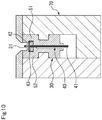
- FIG. 10 shows that in a brush seal piece 30 of a split type brush seal device, a brush 40 in which bundled wire rods 41 are fixed to an attachment portion 42 by welding 43 is nipped by metal plates 51, 52 and temporarily fixed to an assembling welding jig 70, and an outer circumference of the pair of metal plates 51, 52 is assembled by welding 31 in a state where the metal plates 51, 52 are placed along a curvature of the assembling welding jig 70.
- bundled wire rods 41 are nipped by metal plates 51, 52 and temporarily fixed to an assembling welding jig 70, and three parts consisting of the wire rods 41 and the metal plates 51, 52 are assembled by welding 32 in a state where the metal plates 51, 52 are placed along a curvature of the assembling welding jig 70. Therefore, even when a sectional shape in the radial direction of the brush seal piece 30 is the same, the assembling welding jig 70 is required for every curvature of an attachment member of the rotary machine to which the brush seal piece 30 is attached.
- the present invention has been achieved focusing on such a problem, and an objective thereof is to provide a split type brush seal device in which brush seal pieces can be applied to an attached portion having an acceptable curvature, brush seal pieces, and a method of assembling a split type brush seal device.
- a split type brush seal device including:
- the curvature of the plate can be approximated to the curvature of the attached portion.
- the plate can be applied to the attached member having the attached portion having the approximated and acceptable curvature.
- the number of jigs for assembling the brush seal pieces can be reduced.
- the split type brush seal device is characterized in that the biasing means is a fastening member that fastens the plate to the attached member in the radial direction.
- the direction in which the fastening member fastens is identical with a direction in which the plate is deformed so that the curvature of the plate is approximated to the curvature of the attached portion.
- the plate can be deformed following a fastening task of the fastening member, and assembling workability is favorable.
- the split type brush seal device is characterized in that the biasing means is a fastening member that fastens the plate to the attached member in the circumferential direction.
- the design flexibility of the plate on the distal end side of the wire rods is high.
- the split type brush seal device is characterized in that the plurality of brush seal pieces are attached to the attached member, and each of the brush seal pieces has a mating structure for regulating radial movement mutually with the adjoining brush seal piece.
- distal ends of the wire rods of the adjoining brush seal pieces can be formed in a shape along an arc.
- the split type brush seal device is characterized in that the biasing means is configured to deform the plate and cause the curvature of the plate to approximate to the curvature of the attached portion at least before the plate is attached to the attached portion.
- the plate before the plate is attached to the attached portion, the plate is deformed and the curvature is changed.
- a task of attaching the plate to the attached portion is simple.
- Brush seal pieces of a split type brush seal device are characterized in that:
- the biasing force is received by the plurality of receiving portions.
- the curvature of the plate can be changed.
- the brush seal pieces of the split type brush seal device according to a seventh aspect of the present invention is characterized in that each of the brush seal pieces has a mating structure for regulating radial movement mutually with the adjoining brush seal piece.
- the adjoining brush seal pieces can be simply positioned relative to each other.
- the plate can be attached along the curvature of the attached portion.
- the plate can be applied to the attached portion having the approximated and acceptable curvature.
- the method of assembling the split type brush seal device according to a ninth aspect of the present invention is characterized in that the step of attaching is performed by using a fastening member.
- attachment is performed by using the fastening member.
- the curvature of the plate can surely coincide with a desired curvature.
- FIGS. 1 to 4 , 10 , 11 A brush seal according to a first embodiment will be described with reference to FIGS. 1 to 4 , 10 , 11 .
- the left-to-right direction on the paper plane of FIG. 1 is the axial direction
- the direction extending in a radial manner from center O of FIG. 2 is the radial direction
- the direction running along the circumference equally distant from the center O is the circumferential direction.
- a brush seal piece is schematically shown in FIGS. 3 and 4
- one example of the brush seal piece includes structures shown in FIGS. 1 , 10 , 11 .
- FIG. 1 shows an example where a split type brush seal device is assembled in a rotary machine such as a turbine.
- Brush seal pieces 30 are arranged in a channel shape housing portion 21 (attached portion) formed in a housing 20 (attached member) serving as a stator of the rotary machine.
- a sealed gas such as steam and fuel gas of a high pressure side region H inside the rotary machine is suppressed from leaking out to a low pressure side region L.
- a split type brush seal device 10 is formed in a ring shape in which two brush seal pieces 30, 30 divided in the circumferential direction are coupled and housed in the housing portions 21, 21 of two housings 20, 20 divided in the circumferential direction ( FIG. 2 ).
- the brush seal piece 30 mainly includes a low pressure side metal plate 51 (plate), a high pressure side metal plate 52 (plate), and the brush 40.
- the brush 40 is nipped by the metal plates 51, 52 and temporarily fixed to an assembling welding jig 70 ( FIG. 11 ), and three parts consisting of the attachment portion 42 and the metal plates 51, 52 are assembled by electron-beam welding 32 in a state where the metal plates 51, 52 are placed along a curvature of the assembling welding jig 70.
- the low pressure side metal plate 51 and the high pressure side metal plate 52 will be also simply referred to as the metal plates 51, 52.
- the low pressure side metal plate 51 is fastened and fixed to the housing 20 by bolts 60 (fastening means or fastening members) from the radially inner circumferential side in a state where major parts are housed in the housing portion 21.
- shaft portions 62 of the bolts 60 and screw holes 24 of the housing 20 are fastened by screwing, and part of head portions 61 of a larger diameter than the shaft portions 62 are abutted with bottom faces 53b (pressure receiving portions) of recess portions 53 (receiving portions) having arch shape sections of the low pressure side metal plate 51, so that a biasing force in the radial direction is applied to the brush seal piece 30.
- substantially cylindrical spot faces to house the head portions 61 are formed by the recess portions 53 and recess portions 23 of the housing 20.
- the recess portions 53 are formed by pressing, cutting, or the like.
- a wire diameter is 0.05 to 0.5 mm
- a material is steel, a nickel base alloy, a cobalt base alloy, ceramics, or the like.
- a material of both the metal plates 51, 52 is preferably stainless, chromium steel, or the like.
- An assembling order of the split type brush seal device 10 is as follows.
- the brush 40 is nipped by the metal plates 51, 52 and temporarily fixed to the assembling welding jig 70, and three parts consisting of the attachment portion 42 and the metal plates 51, 52 are assembled by the electron-beam welding 32 to be the brush seal piece 30 in a state where an external force is added to the metal plates 51, 52 and the metal plates are forcibly placed along the curvature of the assembling welding jig 70.
- the curvature of both the metal plates 51, 52 of the brush seal piece 30 may be in an acceptable range with respect to a curvature of a bottom face 22 of the housing portion 21, and there is no need to be the substantially same as in the conventional example.
- the acceptable range may be a range in which the curvature of both the metal plates 51, 52 can be forcibly and substantially matched with the curvature of the bottom face 22 by a biasing force by fastening of the bolts 60, for example, the range in which a difference between both the curvatures is 10% or less.
- both the metal plates 51, 52 can be approximated to the curvature of the housing portion 21.
- both the metal plates 51, 52 can be applied to the housing portion 21 having the approximated and acceptable curvature.
- the number of jigs for assembling the brush seal pieces 30 can be reduced.
- the metal plates 51, 52 are attached along the curvature of the housing portion 52.
- the distal ends of the wire rods 41 of the adjoining brush seal pieces 30 are formed in a continuous arc shape in the circumferential direction in a state where the bolts 60 are fastened, and a distance between the distal ends of the wire rods 41 and the rotor 12 can be substantially constant.
- a necessary sealing performance can be ensured.
- the metal plate 51 is fastened to the housing 20 by the bolts 60. Thus, the metal plate 51 is simply attached to the housing 20 with favorable precision.
- the bolts 60 are provided only in the low pressure side region L. Thus, no recess portions are provided on an inner circumference of the housing 20 in the high pressure side region H, so that a flow of the sealed gas in this region is not easily disturbed. It should be noted that provision of bolts only in the high pressure side region H is not prevented and bolts may be provided in both the side regions of the low pressure side region L and the high pressure side region H. In a case where the bolts are provided in both the side regions, the bolts of the low pressure side region L and the bolts of the high pressure side region H are preferably arranged in a zigzag way in the circumferential direction.
- the direction in which the bolts 60 are fastened is the direction in which the metal plates 51, 52 are deformed so that the curvature of the metal plates 51, 52 is approximated to the curvature of the housing portion 21.
- the metal plates 51, 52 can be deformed following a fastening task of the bolts 60, and assembling workability is favorable.
- the recess portions 53 are provided at five points in the circumferential direction. Thus, even when the curvature of the brush seal piece 30 is greater ( FIG. 4(a) ) or smaller ( FIG. 4(b) ), the brush seal piece 30 can be approximated to the curvature of the housing portion 21 with favorable precision. In order to deal with only the time when the curvature of the brush seal piece 30 is smaller ( FIG. 4(b) ), the recess portion 53 may also be provided in center in the circumferential direction of the brush seal piece 30.
- FIG. 5 A configuration where a bolt 60 is fastened in the circumferential direction is different from the first embodiment. Description of the same configurations as the first embodiment will be omitted.
- a recess portion 23' and a screw hole 24' are formed on a side face of a housing 20, and a recess portion 53' (receiving portion) is provided in a circumferential end portion of a low pressure side metal plate 51.
- FIGS. 6 , 7 Three examples in which an outer shape of a brush seal piece 30 and a housing portion of a housing 20 are different from the first embodiment will be described. Description of the same configurations as the first embodiment will be omitted.
- the brush seal piece 30 shown in FIG. 6(a) has the same configuration as the brush seal piece 30 shown in FIGS. 3 , 5 .
- a low pressure side metal plate 51' may have a plate shape portion 51A and a projecting portion 51B which is axially longer than the plate shape portion 51A.
- the brush seal piece 30 has the projecting portion 51B.
- the brush seal piece 30 is inserted into a housing 21' having a substantially L shape section ( FIG. 7(b) ) in the circumferential direction, fixed to the housing 20 by a bolt 60, and assembled.
- a high pressure side metal plate 52' is formed in the same way as the low pressure side metal plate 51' of FIG. 6(b) .
- the brush seal piece 30 is inserted into a housing portion 21" having a substantially T shape section ( FIG. 7(c) ) in the circumferential direction, fixed to the housing 20 by the bolt 60, and assembled.
- the brush seal piece 30 has the projecting portion 51B as in FIGS. 6(b), 6(c)
- the projecting portion 51B can also be biased by a bolt 60' as shown by broken lines in FIGS. 7(b), 7(c) .
- a projecting portion 52B can also be biased by the bolt.
- a position where a recess portion 53 is provided may be a circumferential end portion as well as the second embodiment.
- FIGS. 8 , 9 a split type brush seal device according to a fourth embodiment will be described with reference to FIGS. 8 , 9 .
- the number of brush seal pieces 30 arranged in one housing 20 is different from FIG. 2 .
- the fourth embodiment is particularly suitable for a configuration where bolts 60 are fastened in the circumferential direction as in the second embodiment. Description of the same configurations as the first and second embodiments will be omitted.
- recess portions 53' corresponding to the second embodiment are omitted.
- a mating structure for regulating radial movement mutually with the adjoining brush seal piece 30 is preferably provided in a circumferential end portion of the brush seal piece 30.
- pin mating using an insertion hole 58A and an insertion pin 58a, key mating using an insertion groove 58B and a key member 58b, overlap mating using a circumferentially projecting portion 58C of a low pressure side metal plate 51 and a circumferential cutout 58c, overlap mating using a circumferentially projecting portion 58D of a high pressure side metal plate 52 and a circumferential cutout 58d, and overlap mating using the circumferentially projecting portion 58C of the low pressure side metal plate 51 and the circumferential cutout 58c, and the circumferentially projecting portion 58D of the high pressure side metal plate 52 and the circumferential cutout 58d can be adopted as shown in FIGS. 9(a) to 9(e) .
- the adjoining brush seal pieces 30, 30 can be connected by using the mating structure of FIG. 9(e) .
- the brush seal device of the fourth embodiment can be assembled without increasing the bolts 60.
- the adjoining brush seal pieces 30, 30 can regulate radial movement mutually with each other. Irrespective of a shape of the circumferential end face (shape such as inclination and non-inclination) of the brush seal piece 30, by integrally and temporarily holding the plural brush seal pieces 30, 30... by the mating structure, a task of housing the brush seal pieces 30, 30... in a housing portion 21 is easily performed.
- a rotor on the inner circumferential side of the split type brush seal device 10 is sealed is described in the above embodiments.
- a rotor on the outer circumferential side of a split type brush seal device may be sealed.
- a distal end of a brush on the radially outer side is brought close to or into contact with the rotor.
- the bolts 60 having screw portions are described as an example.
- the means may be fastening members other than the bolts such as clips. Further, fixing may be done by welding other than the fastening members or press-fitting into the housing 20.
- the means may be any means that deforms the brush seal piece 30 into a desired curvature in a state where the brush seal piece 30 is attached to the housing 20.
- the metal plate is described as an example.
- a material of the plate is not limited to metal.
- the plate may be anything to satisfy specifications such as mechanical strength, heat resistance, and corrosion resistance, and to be forcibly deformed to change a curvature.
- the brush seal piece 30 may be deformed (for example, by plastic deformation) by a biasing means such as a roller, and the curvature of the brush seal piece 30 is changed.
- a biasing means such as a roller
- the biasing means such as the bolts 60 described in the first to fourth embodiments may be used together.
- the housing 20 serving as the stator is described as an example.
- this housing 20 may form a casing of the rotary machine or may be detachably attached to the casing.
- the housing 20 may be divided in the axial direction.
Landscapes
- Engineering & Computer Science (AREA)
- General Engineering & Computer Science (AREA)
- Mechanical Engineering (AREA)
- Chemical & Material Sciences (AREA)
- Combustion & Propulsion (AREA)
- Manufacturing & Machinery (AREA)
- Sealing Devices (AREA)
- Turbine Rotor Nozzle Sealing (AREA)
Abstract
Description
- The present invention relates to a split type brush seal device that seals a clearance between two relatively rotating members of a rotary machine such as a turbine, brush seal pieces, and a method of assembling a split type brush seal device.
- In a rotary machine such as a turbine, a seal device is used for suppressing leakage of gas from the high pressure side to the low pressure side along the circumference of a rotor. It is desired that a seal follows variations of a clearance between a stator and the rotor of the rotary machine and eccentricity between the stator and the rotor and exerts sealing performance. From such a viewpoint, a brush seal in which bundled wire rods are fixed to a metal plate is adopted in place of a labyrinth seal. In order to simplify tasks of attaching and detaching the brush seal to the rotary machine, a split type brush seal device in which a brush seal is divided into arc brush seal pieces and plural brush seal pieces are placed side by side in the circumferential direction is proposed (for example, refer to Patent Literatures 1, 2).
-
- Patent Literature 1: Japanese Laid-open Patent Publication
2008-121512 FIGS. 2 and3 ) - Patent Literature 2: PCT International Application No.
WO/2008/004590 ([0018] to [0023],FIGS. 1 to 4 ) - As shown in
FIG. 10 , in abrush seal piece 30 of a split type brush seal device, abrush 40 in which bundledwire rods 41 are fixed to anattachment portion 42 bywelding 43 is nipped bymetal plates welding jig 70, and an outer circumference of the pair ofmetal plates welding 31 in a state where themetal plates welding jig 70. Alternatively, as shown inFIG. 11 , in abrush seal piece 30 of a split type brush seal device, bundledwire rods 41 are nipped bymetal plates welding jig 70, and three parts consisting of thewire rods 41 and themetal plates metal plates welding jig 70. Therefore, even when a sectional shape in the radial direction of thebrush seal piece 30 is the same, the assemblingwelding jig 70 is required for every curvature of an attachment member of the rotary machine to which thebrush seal piece 30 is attached. - The present invention has been achieved focusing on such a problem, and an objective thereof is to provide a split type brush seal device in which brush seal pieces can be applied to an attached portion having an acceptable curvature, brush seal pieces, and a method of assembling a split type brush seal device.
- In order to solve the foregoing problem, a split type brush seal device according to a first aspect of the present invention including:
- a plurality of brush seal pieces having bundled wire rods; and
- an attached member in which the plurality of brush seal pieces is attached to an attached portion in the circumferential direction, is characterized in that:
- each of the brush seal pieces has a plate of arc shape to which the bundled wire rods are fixed; and
- the split type brush seal device further comprises biasing means that forcibly causes a curvature of the plate to approximate to a curvature of the attached portion.
- According to the first aspect, the curvature of the plate can be approximated to the curvature of the attached portion. Thus, the plate can be applied to the attached member having the attached portion having the approximated and acceptable curvature. As a result, the number of jigs for assembling the brush seal pieces can be reduced.
- The split type brush seal device according to a second aspect of the present invention is characterized in that the biasing means is a fastening member that fastens the plate to the attached member in the radial direction.
- According to the second aspect, the direction in which the fastening member fastens is identical with a direction in which the plate is deformed so that the curvature of the plate is approximated to the curvature of the attached portion. Thus, the plate can be deformed following a fastening task of the fastening member, and assembling workability is favorable.
- The split type brush seal device according to a third aspect of the present invention is characterized in that the biasing means is a fastening member that fastens the plate to the attached member in the circumferential direction.
- According to the third aspect, there is no need for providing a fastening member on the distal end side of the wire rods. Thus, the design flexibility of the plate on the distal end side of the wire rods is high.
- The split type brush seal device according to a fourth aspect of the present invention is characterized in that the plurality of brush seal pieces are attached to the attached member, and each of the brush seal pieces has a mating structure for regulating radial movement mutually with the adjoining brush seal piece.
- According to the fourth aspect, even in a case where the number of divided portions is different between the brush seal piece and the attached member, distal ends of the wire rods of the adjoining brush seal pieces can be formed in a shape along an arc.
- The split type brush seal device according to a fifth aspect of the present invention is characterized in that the biasing means is configured to deform the plate and cause the curvature of the plate to approximate to the curvature of the attached portion at least before the plate is attached to the attached portion.
- According to the fifth aspect, before the plate is attached to the attached portion, the plate is deformed and the curvature is changed. Thus, a task of attaching the plate to the attached portion is simple.
- Brush seal pieces of a split type brush seal device according to a sixth aspect of the present invention, the brush seal pieces being attached to an attached portion of an attached member in the circumferential direction, are characterized in that:
- each of the brush seal pieces includes a plate of arc shape to which bundled wire rods are fixed; and
- the plate has a plurality of receiving portions that receive a biasing force in the radial direction upon the attachment of the brush seal pieces.
- According to the sixth aspect, the biasing force is received by the plurality of receiving portions. Thus, the curvature of the plate can be changed.
- The brush seal pieces of the split type brush seal device according to a seventh aspect of the present invention is characterized in that each of the brush seal pieces has a mating structure for regulating radial movement mutually with the adjoining brush seal piece.
- According to the seventh aspect, the adjoining brush seal pieces can be simply positioned relative to each other.
- A method of assembling a split type brush seal device according to an eighth aspect of the present invention is characterized by including the steps of:
- preparing a brush seal piece in which bundled wire rods are fixed to a plate of arc shape;
- preparing an attached member provided with an attached portion of arc shape, the attachment portion having a different curvature from the plate; and
- attaching the plate to the attached portion so that a curvature difference is reduced between the plate and the attached portion.
- According to the eighth aspect, the plate can be attached along the curvature of the attached portion. Thus, even when the curvature is different between the plate and the attached portion, the plate can be applied to the attached portion having the approximated and acceptable curvature.
- The method of assembling the split type brush seal device according to a ninth aspect of the present invention is characterized in that the step of attaching is performed by using a fastening member.
- According to the ninth aspect, attachment is performed by using the fastening member. Thus, the curvature of the plate can surely coincide with a desired curvature.
-
-
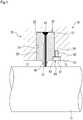
FIG. 1 is a sectional view showing a state where a split type brush seal device in a first embodiment is assembled in a rotary machine; -
FIG. 2 is a side view showing part of the split type brush seal device of the first embodiment; -
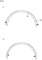
FIG. 3 is an illustrative view showing assembling of a brush seal piece of the first embodiment:FIG. 3(a) is a view showing a state before both end portions of the brush seal piece are fastened; andFIG. 3(b) is a view showing a state after both the end portions and a center portion are fastened; -
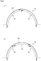
FIG. 4 is a view illustrating a change in a curvature of the brush seal piece of the first embodiment:FIG. 4(a) is an illustrative view of a case where the curvature of the brush seal piece is greater than an attached portion; andFIG. 4(b) is an illustrative view of a case where the curvature of the brush seal piece is smaller than the attached portion; -
FIG. 5 is an illustrative view showing assembling of a brush seal piece of a second embodiment:FIG. 5(a) is a view showing a state before both end portions of the brush seal piece are fastened; andFIG. 5(b) is a view showing a state after both the end portions are fastened; -
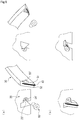
FIG. 6 is a perspective view showing a modified example of a brush seal piece of a third embodiment:FIG. 6(a) shows a plate having a substantially rectangular section;FIG. 6(b) shows a plate having a substantially L shape section; andFIG. 6(c) shows a plate having a substantially T shape section; -
FIG. 7 is a sectional view of a split type brush seal device of the third embodiment:FIGS. 7(a), 7(b), 7(c) are sectional views corresponding to the brush seal pieces ofFIGS. 6(a), 6(b), 6(c) , respectively; -
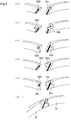
FIG. 8 is a view illustrating a change in a curvature of brush seal pieces of a fourth embodiment:FIG. 8(a) is an illustrative view of a case where two brush seal pieces are arranged in an attached member; andFIG. 8(b) is an illustrative view of a case where three brush seal pieces are arranged in the attached member; -
FIG. 9 is a perspective view for illustrating connection of the adjoining brush seal pieces of the fourth embodiment; -
FIG. 10 is a sectional view for illustrating assembling of a conventional brush seal piece; and -
FIG. 11 is a sectional view for illustrating assembling of a conventional brush seal piece. - Modes for implementing a split type brush seal device, brush seal pieces, and a method of assembling a split type brush seal device will be described below on the basis of embodiments.
- A brush seal according to a first embodiment will be described with reference to
FIGS. 1 to 4 ,10 ,11 . In the following description, the left-to-right direction on the paper plane ofFIG. 1 is the axial direction, the direction extending in a radial manner from center O ofFIG. 2 is the radial direction, and the direction running along the circumference equally distant from the center O is the circumferential direction. It should be noted that a brush seal piece is schematically shown inFIGS. 3 and4 , and one example of the brush seal piece includes structures shown inFIGS. 1 ,10 ,11 . -
FIG. 1 shows an example where a split type brush seal device is assembled in a rotary machine such as a turbine.Brush seal pieces 30 are arranged in a channel shape housing portion 21 (attached portion) formed in a housing 20 (attached member) serving as a stator of the rotary machine. By bringing distal ends ofwire rods 41 close to or into contact with arotor 12 of the rotary machine, a sealed gas such as steam and fuel gas of a high pressure side region H inside the rotary machine is suppressed from leaking out to a low pressure side region L. A split typebrush seal device 10 is formed in a ring shape in which twobrush seal pieces housing portions housings FIG. 2 ). - In a
brush 40, an outer circumference of the bundledwire rods 41 is integrated by welding, and this outer circumference serves as anattachment portion 42. Thebrush seal piece 30 mainly includes a low pressure side metal plate 51 (plate), a high pressure side metal plate 52 (plate), and thebrush 40. Thebrush 40 is nipped by themetal plates FIG. 11 ), and three parts consisting of theattachment portion 42 and themetal plates beam welding 32 in a state where themetal plates welding jig 70. It should be noted that the low pressureside metal plate 51 and the high pressureside metal plate 52 will be also simply referred to as themetal plates - In the
brush seal piece 30, the low pressureside metal plate 51 is fastened and fixed to thehousing 20 by bolts 60 (fastening means or fastening members) from the radially inner circumferential side in a state where major parts are housed in thehousing portion 21. In detail,shaft portions 62 of thebolts 60 and screwholes 24 of thehousing 20 are fastened by screwing, and part ofhead portions 61 of a larger diameter than theshaft portions 62 are abutted with bottom faces 53b (pressure receiving portions) of recess portions 53 (receiving portions) having arch shape sections of the low pressureside metal plate 51, so that a biasing force in the radial direction is applied to thebrush seal piece 30. It should be noted that substantially cylindrical spot faces to house thehead portions 61 are formed by therecess portions 53 andrecess portions 23 of thehousing 20. Therecess portions 53 are formed by pressing, cutting, or the like. - Regarding the
wire rods 41, a wire diameter is 0.05 to 0.5 mm, and a material is steel, a nickel base alloy, a cobalt base alloy, ceramics, or the like. A material of both themetal plates - An assembling order of the split type
brush seal device 10 is as follows. By using the jig ofFIG. 11 , thebrush 40 is nipped by themetal plates welding jig 70, and three parts consisting of theattachment portion 42 and themetal plates beam welding 32 to be thebrush seal piece 30 in a state where an external force is added to themetal plates welding jig 70. The curvature of both themetal plates brush seal piece 30 may be in an acceptable range with respect to a curvature of abottom face 22 of thehousing portion 21, and there is no need to be the substantially same as in the conventional example. It should be noted that the acceptable range may be a range in which the curvature of both themetal plates bottom face 22 by a biasing force by fastening of thebolts 60, for example, the range in which a difference between both the curvatures is 10% or less. - Next, after the
brush seal piece 30 is inserted into thehousing portion 21 from the radially inner side, threebolts 60 are screwed into the screw holes 24 from the radially inner side, so that thebrush seal piece 30 is fixed to thehousing 20. As shown inFIG. 4(a) , when the curvature of thebrush seal piece 30 is greater than the curvature of thebottom face 22 of thehousing portion 21, thebrush seal piece 30 is forcibly deformed so that both end portions are expanded in the arrow directions. Meanwhile, when the curvature is smaller, the brush seal piece is forcibly deformed so as to be crushed. In a state where thebolts 60 are fastened, therecess portions 53 of themetal plate 51 receive the biasing force from thebolts 60. Thus, internal stress generating moment about curvature center is generated in both themetal plates bottom face 22 of thehousing portion 21 is increased. It should be noted that the curvature of thebottom face 22 of thehousing portion 21 indicates the curvature of thehousing portion 21. Thus, the curvature of thebottom face 22 will be simply called as the curvature of thehousing portion 21. - In such a way, the curvature of both the
metal plates housing portion 21. Thus, both themetal plates housing portion 21 having the approximated and acceptable curvature. As a result, the number of jigs for assembling thebrush seal pieces 30 can be reduced. - When depth L1 serving as radial length of the housing portion 21 (refer to
FIG. 3 ) and depth L2 serving as radial length of both themetal plates housing 20 and inner circumferential faces of both themetal plates bolts 60 may be fastened with both the inner circumferential faces as benchmarks for assembling positions. Thus, positioning in the depth direction at the time of assembling is easy. - The
metal plates housing portion 52. Thus, even when the curvature is different between themetal plates housing portion 21 before attachment, the distal ends of thewire rods 41 of the adjoiningbrush seal pieces 30 are formed in a continuous arc shape in the circumferential direction in a state where thebolts 60 are fastened, and a distance between the distal ends of thewire rods 41 and therotor 12 can be substantially constant. Thus, a necessary sealing performance can be ensured. - The
metal plate 51 is fastened to thehousing 20 by thebolts 60. Thus, themetal plate 51 is simply attached to thehousing 20 with favorable precision. - The
bolts 60 are provided only in the low pressure side region L. Thus, no recess portions are provided on an inner circumference of thehousing 20 in the high pressure side region H, so that a flow of the sealed gas in this region is not easily disturbed. It should be noted that provision of bolts only in the high pressure side region H is not prevented and bolts may be provided in both the side regions of the low pressure side region L and the high pressure side region H. In a case where the bolts are provided in both the side regions, the bolts of the low pressure side region L and the bolts of the high pressure side region H are preferably arranged in a zigzag way in the circumferential direction. - The direction in which the
bolts 60 are fastened is the direction in which themetal plates metal plates housing portion 21. Thus, themetal plates bolts 60, and assembling workability is favorable. - The
recess portions 53 are provided at five points in the circumferential direction. Thus, even when the curvature of thebrush seal piece 30 is greater (FIG. 4(a) ) or smaller (FIG. 4(b) ), thebrush seal piece 30 can be approximated to the curvature of thehousing portion 21 with favorable precision. In order to deal with only the time when the curvature of thebrush seal piece 30 is smaller (FIG. 4(b) ), therecess portion 53 may also be provided in center in the circumferential direction of thebrush seal piece 30. - Next, a split type brush seal device according to a second embodiment will be described with reference to
FIG. 5 . A configuration where abolt 60 is fastened in the circumferential direction is different from the first embodiment. Description of the same configurations as the first embodiment will be omitted. - A
recess portion 23' and a screw hole 24' are formed on a side face of ahousing 20, and a recess portion 53' (receiving portion) is provided in a circumferential end portion of a low pressureside metal plate 51. After abrush seal piece 30 is inserted into ahousing portion 21 from the radially inner side, thebolt 60 is screwed into the screw hole 24' in the circumferential direction in a state where a curvature of thebrush seal piece 30 is forcibly changed to be a curvature of thehousing portion 21, so that thebrush seal piece 30 is fixed to thehousing 20. - There is no need for providing the
bolt 60 on the distal end side ofwire rods 41. Thus, the design flexibility of the low pressureside metal plate 51 on the distal end side of thewire rods 41 is high. - Next, a split type brush seal device according to a third embodiment will be described with reference to
FIGS. 6 ,7 . Three examples in which an outer shape of abrush seal piece 30 and a housing portion of ahousing 20 are different from the first embodiment will be described. Description of the same configurations as the first embodiment will be omitted. - The
brush seal piece 30 shown inFIG. 6(a) has the same configuration as thebrush seal piece 30 shown inFIGS. 3 ,5 . - As shown in
FIG. 6(b) , a low pressure side metal plate 51' may have aplate shape portion 51A and a projectingportion 51B which is axially longer than theplate shape portion 51A. In this case, thebrush seal piece 30 has the projectingportion 51B. Thus, thebrush seal piece 30 is inserted into a housing 21' having a substantially L shape section (FIG. 7(b) ) in the circumferential direction, fixed to thehousing 20 by abolt 60, and assembled. - As shown in
FIG. 6(c) , a high pressure side metal plate 52' is formed in the same way as the low pressure side metal plate 51' ofFIG. 6(b) . In this case, thebrush seal piece 30 is inserted into ahousing portion 21" having a substantially T shape section (FIG. 7(c) ) in the circumferential direction, fixed to thehousing 20 by thebolt 60, and assembled. - In a case where the
brush seal piece 30 has the projectingportion 51B as inFIGS. 6(b), 6(c) , instead of biasing of theplate shape portion 51A to the inner circumferential side, the projectingportion 51B can also be biased by a bolt 60' as shown by broken lines inFIGS. 7(b), 7(c) . In this case, there is a need for providing abolt insertion hole 25 in thehousing 20. In a case ofFIG. 6(c) , a projectingportion 52B can also be biased by the bolt. - It should be noted that in the examples of
FIGS. 6(a) to 6(c) , a position where arecess portion 53 is provided may be a circumferential end portion as well as the second embodiment. - Next, a split type brush seal device according to a fourth embodiment will be described with reference to
FIGS. 8 ,9 . The number ofbrush seal pieces 30 arranged in onehousing 20 is different fromFIG. 2 . The fourth embodiment is particularly suitable for a configuration wherebolts 60 are fastened in the circumferential direction as in the second embodiment. Description of the same configurations as the first and second embodiments will be omitted. InFIGS. 8 ,9 , recess portions 53' corresponding to the second embodiment are omitted. - In a case where plural
brush seal pieces 30 are arranged in onehousing 20, due to inclination of circumferential end faces of thebrush seal pieces 30, upon receiving a force from the circumferential direction, the circumferential end faces of the adjoiningbrush seal pieces FIGS. 8(a), 8(b) . Therefore, a mating structure for regulating radial movement mutually with the adjoiningbrush seal piece 30 is preferably provided in a circumferential end portion of thebrush seal piece 30. - As the mating structure, pin mating using an
insertion hole 58A and aninsertion pin 58a, key mating using aninsertion groove 58B and akey member 58b, overlap mating using acircumferentially projecting portion 58C of a low pressureside metal plate 51 and acircumferential cutout 58c, overlap mating using acircumferentially projecting portion 58D of a high pressureside metal plate 52 and acircumferential cutout 58d, and overlap mating using thecircumferentially projecting portion 58C of the low pressureside metal plate 51 and thecircumferential cutout 58c, and thecircumferentially projecting portion 58D of the high pressureside metal plate 52 and thecircumferential cutout 58d can be adopted as shown inFIGS. 9(a) to 9(e) . For example, as shown inFIG. 9 (e'), the adjoiningbrush seal pieces FIG. 9(e) . - By using the mating structure in such a way, even in a case where the
brush seal piece 30 of the second embodiment is further divided in the circumferential direction, that is, even when the number of portions into which the brush seal piece is divided is equal to or more than the number of the bolts 60 (two bolts), the brush seal device of the fourth embodiment can be assembled without increasing thebolts 60. Even when the circumferential end face of thebrush seal piece 30 is inclined, the adjoiningbrush seal pieces brush seal piece 30, by integrally and temporarily holding the pluralbrush seal pieces brush seal pieces housing portion 21 is easily performed. - The embodiments of the present invention are described above with the drawings. However, specific configurations are not limited to these embodiments and the present invention also includes modifications and additions within a range not departing from the gist of the present invention.
- For example, the example where the
rotor 12 on the inner circumferential side of the split typebrush seal device 10 is sealed is described in the above embodiments. However, a rotor on the outer circumferential side of a split type brush seal device may be sealed. In this case, a distal end of a brush on the radially outer side is brought close to or into contact with the rotor. - As a means that attaches and fixes the
brush seal piece 30 to thehousing 20, thebolts 60 having screw portions are described as an example. However, the means may be fastening members other than the bolts such as clips. Further, fixing may be done by welding other than the fastening members or press-fitting into thehousing 20. In sum, the means may be any means that deforms thebrush seal piece 30 into a desired curvature in a state where thebrush seal piece 30 is attached to thehousing 20. - As the plate, the metal plate is described as an example. However, a material of the plate is not limited to metal. The plate may be anything to satisfy specifications such as mechanical strength, heat resistance, and corrosion resistance, and to be forcibly deformed to change a curvature.
- The example where the curvature of the
brush seal piece 30 is changed by thebolts 60 at the time of attaching thebrush seal piece 30 to thehousing 20 is described. However, before attaching to thehousing 20, thebrush seal piece 30 may be deformed (for example, by plastic deformation) by a biasing means such as a roller, and the curvature of thebrush seal piece 30 is changed. In this case, when the curvature substantially matches between thebrush seal piece 30 and thehousing portion 21 of thehousing 20, deformation of thebrush seal piece 30 by thebolts 60 is not required. Further, the biasing means such as a roller and the biasing means such as thebolts 60 described in the first to fourth embodiments may be used together. - As the attached member, the
housing 20 serving as the stator is described as an example. However, thishousing 20 may form a casing of the rotary machine or may be detachably attached to the casing. Thehousing 20 may be divided in the axial direction. -
- 10
- Split type brush seal device
- 20
- Housing (attached member)
- 21
- Housing portion (attached portion)
- 23
- Recess portion (receiving portion)
- 24
- Screw hole
- 30
- Brush seal piece
- 40
- Brush
- 51, 51'
- Low pressure side metal plate (plate)
- 52, 52'
- High pressure side metal plate (plate)
- 53, 53'
- Recess portion (receiving portion)
- 53b
- Bottom face
- 60
- Bolt (biasing means, fastening member)
- H
- High pressure side region
- L
- Low pressure side region
Claims (9)
- A split type brush seal device comprising:a plurality of brush seal pieces having bundled wire rods; andan attached member in which the plurality of brush seal pieces is attached to an attached portion in the circumferential direction, characterized in that:each of the brush seal pieces has a plate of arc shape to which the bundled wire rods are fixed; andthe split type brush seal device further comprises a biasing means that forcibly causes a curvature of the plate to approximate to a curvature of the attached portion.
- The split type brush seal device according to claim 1, characterized in that:the biasing means is a fastening member that fastens the plate to the attached member in the radial direction.
- The split type brush seal device according to claim 1, characterized in that:the biasing means is a fastening member that fastens the plate to the attached member in the circumferential direction.
- The split type brush seal device according to claim 3, characterized in that:the plurality of brush seal pieces is attached to the attached member; andeach of the brush seal pieces has a mating structure for regulating radial movement mutually with the adjoining brush seal piece.
- The split type brush seal device according to claim 1, characterized in that:the biasing means is configured to deform the plate and cause the curvature of the plate to approximate to the curvature of the attached portion at least before the plate is attached to the attached portion.
- Brush seal pieces of a split type brush seal device, the brush seal pieces being attached to an attached portion of an attached member in the circumferential direction, characterized in that:each of the brush seal pieces includes a plate of arc shape to which bundled wire rods are fixed; andthe plate has a plurality of receiving portions that receive a biasing force in the radial direction upon the attachment of the brush seal pieces.
- The brush seal pieces of the split type brush seal device according to claim 6, characterized in that:each of the brush seal pieces has a mating structure for regulating radial movement mutually with the adjoining brush seal piece.
- A method of assembling a split type brush seal device, characterized by comprising the steps of:preparing a brush seal piece in which bundled wire rods are fixed to a plate of arc shape;preparing an attached member provided with an attached portion of arc shape, the attached portion having a different curvature from the plate; andattaching the plate to the attached portion so that a curvature difference is reduced between the plate and the attached portion.
- The method of assembling the split type brush seal device according to claim 8, characterized in that:the step of attaching is performed by using a fastening member.
Applications Claiming Priority (2)
| Application Number | Priority Date | Filing Date | Title |
|---|---|---|---|
| JP2015045767 | 2015-03-09 | ||
| PCT/JP2016/056565 WO2016143657A1 (en) | 2015-03-09 | 2016-03-03 | Divided-type brush seal device, brush seal piece, and method for assembling divided-type brush seal device |
Publications (3)
| Publication Number | Publication Date |
|---|---|
| EP3270014A1 true EP3270014A1 (en) | 2018-01-17 |
| EP3270014A4 EP3270014A4 (en) | 2019-01-09 |
| EP3270014B1 EP3270014B1 (en) | 2020-11-11 |
Family
ID=56879385
Family Applications (1)
| Application Number | Title | Priority Date | Filing Date |
|---|---|---|---|
| EP16761627.5A Active EP3270014B1 (en) | 2015-03-09 | 2016-03-03 | Divided-type brush seal device |
Country Status (6)
| Country | Link |
|---|---|
| US (1) | US10502322B2 (en) |
| EP (1) | EP3270014B1 (en) |
| JP (1) | JP6644444B2 (en) |
| KR (1) | KR101939733B1 (en) |
| CN (1) | CN107208801B (en) |
| WO (1) | WO2016143657A1 (en) |
Families Citing this family (5)
| Publication number | Priority date | Publication date | Assignee | Title |
|---|---|---|---|---|
| DE102016200343A1 (en) * | 2016-01-14 | 2017-07-20 | MTU Aero Engines AG | Method for producing a brush seal with inclined bristles |
| CN107965391A (en) * | 2017-11-23 | 2018-04-27 | 中国航发沈阳黎明航空发动机有限责任公司 | A kind of seal structure between the quiet rotor of aero-engine |
| DE102020209326A1 (en) | 2020-07-23 | 2022-01-27 | MTU Aero Engines AG | Fastening device for segmented brush seals in a seal carrier |
| US12018567B2 (en) * | 2022-05-31 | 2024-06-25 | Pratt & Whitney Canada Corp. | Joint between gas turbine engine components with bonded fastener(s) |
| CN115013069B (en) * | 2022-07-06 | 2024-09-27 | 中国航发湖南动力机械研究所 | Turbine rotor cooling system and aeroengine |
Family Cites Families (35)
| Publication number | Priority date | Publication date | Assignee | Title |
|---|---|---|---|---|
| US2878048A (en) * | 1954-03-18 | 1959-03-17 | Osborn Mfg Co | Brush seal and the like |
| US5114159A (en) * | 1991-08-05 | 1992-05-19 | United Technologies Corporation | Brush seal and damper |
| DE19613510C1 (en) * | 1996-04-04 | 1997-04-24 | Mtu Muenchen Gmbh | Brush seal for sealing ring-shaped gap between rotor-stator arrangement |
| JPH11257014A (en) | 1998-03-06 | 1999-09-21 | Toshiba Corp | Working fluid leakage prevention device for axial turbine |
| US6105966A (en) * | 1998-08-10 | 2000-08-22 | General Electric Company | Brush seal segment |
| US6257588B1 (en) | 1998-09-22 | 2001-07-10 | General Electric Company | Brush seal and rotary machine including such brush seal |
| JP2000120878A (en) * | 1998-10-20 | 2000-04-28 | Eagle Eg & G Aerospace Kk | Brush type sealing device |
| JP2001050396A (en) | 1999-08-05 | 2001-02-23 | Toshiba Corp | Brush seal device |
| US6390476B1 (en) | 2000-09-08 | 2002-05-21 | General Electric Company | Heat-resistant magnetic silicone rubber brush seals in turbomachinery and methods of application |
| US6464230B1 (en) | 2000-10-19 | 2002-10-15 | General Electric Company | Flexible magnetic rubber brush seal for generators |
| JP4719370B2 (en) * | 2001-03-30 | 2011-07-06 | イーグル・エンジニアリング・エアロスペース株式会社 | Brush seal device |
| US7077573B2 (en) * | 2001-06-11 | 2006-07-18 | Tribotek, Inc. | Contact bearing |
| JP2003004145A (en) * | 2001-06-20 | 2003-01-08 | Mitsubishi Heavy Ind Ltd | Seal for rotary shaft |
| US8181965B2 (en) | 2002-06-27 | 2012-05-22 | United Technologies Corporation | Replaceable brush seal elements |
| US7093835B2 (en) * | 2002-08-27 | 2006-08-22 | United Technologies Corporation | Floating brush seal assembly |
| CN1324221C (en) | 2003-05-21 | 2007-07-04 | 三菱重工业株式会社 | Shaft seal mechanism |
| JP2007263376A (en) | 2003-05-21 | 2007-10-11 | Mitsubishi Heavy Ind Ltd | Shaft seal mechanism |
| DE102004038933A1 (en) * | 2004-08-11 | 2006-02-23 | Mtu Aero Engines Gmbh | sealing arrangement |
| US7226054B2 (en) * | 2004-12-14 | 2007-06-05 | United Technologies Corporation | Clamp lock brush seal assembly |
| US20060267291A1 (en) | 2005-05-25 | 2006-11-30 | Mark Addis | Brush seal assembly and method of assembling same |
| US20090315272A1 (en) * | 2006-07-06 | 2009-12-24 | Eagle Industry Co., Ltd. | Brush seal device |
| EP1892442A1 (en) * | 2006-08-18 | 2008-02-27 | Siemens Aktiengesellschaft | Brush seal for a turbomachine |
| JP2008121512A (en) | 2006-11-10 | 2008-05-29 | Mitsubishi Heavy Ind Ltd | Brush seal and turbine using same |
| CA2631609A1 (en) * | 2007-05-22 | 2008-11-22 | Tyco Healthcare Group Lp | Access assembly with whisker seal |
| US9512922B2 (en) * | 2009-11-24 | 2016-12-06 | Honeywell International Inc. | Sealing apparatus and engines |
| WO2012082805A2 (en) * | 2010-12-13 | 2012-06-21 | Sealeze A Unit Of Jason, Inc. | High temperature device shaft brush seal assembly, brush seal, and mounting arrangement |
| US8794918B2 (en) * | 2011-01-07 | 2014-08-05 | General Electric Company | System for adjusting brush seal segments in turbomachine |
| US9255486B2 (en) * | 2011-03-28 | 2016-02-09 | General Electric Company | Rotating brush seal |
| US8366115B2 (en) * | 2011-06-30 | 2013-02-05 | United Technologies Corporation | Repairable double sided brush seal |
| DK2594790T3 (en) * | 2011-11-17 | 2015-06-01 | Alstom Renewable Technologies | seal assembly |
| US20130170979A1 (en) * | 2012-01-04 | 2013-07-04 | General Electric Company | Double ended brush seal assembly for a compressor |
| US8919633B2 (en) * | 2012-01-04 | 2014-12-30 | General Electric Company | Seal assembly and method for assembling a turbine |
| US20130300067A1 (en) * | 2012-05-14 | 2013-11-14 | General Electric Company | System for sealing a gas path in a turbine |
| CN104583650B (en) * | 2013-02-06 | 2017-07-14 | 伊格尔工业股份有限公司 | Brush seal |
| CN105275505B (en) * | 2014-06-09 | 2017-06-16 | 斗山重工业株式会社 | Brush seal assembly |
-
2016
- 2016-03-03 CN CN201680010495.3A patent/CN107208801B/en active Active
- 2016-03-03 KR KR1020177024049A patent/KR101939733B1/en active Active
- 2016-03-03 JP JP2017505276A patent/JP6644444B2/en active Active
- 2016-03-03 EP EP16761627.5A patent/EP3270014B1/en active Active
- 2016-03-03 US US15/551,568 patent/US10502322B2/en active Active
- 2016-03-03 WO PCT/JP2016/056565 patent/WO2016143657A1/en not_active Ceased
Also Published As
| Publication number | Publication date |
|---|---|
| US10502322B2 (en) | 2019-12-10 |
| CN107208801A (en) | 2017-09-26 |
| CN107208801B (en) | 2020-03-13 |
| WO2016143657A1 (en) | 2016-09-15 |
| EP3270014B1 (en) | 2020-11-11 |
| KR101939733B1 (en) | 2019-01-18 |
| JPWO2016143657A1 (en) | 2017-12-21 |
| US20180045317A1 (en) | 2018-02-15 |
| KR20170107557A (en) | 2017-09-25 |
| JP6644444B2 (en) | 2020-02-12 |
| EP3270014A4 (en) | 2019-01-09 |
Similar Documents
| Publication | Publication Date | Title |
|---|---|---|
| US10502322B2 (en) | Split type brush seal device, brush seal pieces, and method of assembling split type brush seal device | |
| CN101652534B (en) | Vane ring and axial flow compressor using the vane ring | |
| US8517673B2 (en) | Lamellar seal for a turbomachine | |
| US7364165B2 (en) | Shaft seal mechanism | |
| EP3023580B1 (en) | Gas turbine with plurality of tie rods and method of assembling the same | |
| US10247005B2 (en) | Blade or vane arrangement for a turbomachine | |
| JP5634715B2 (en) | Method for manufacturing compliant plate seal assembly | |
| EP3246542A1 (en) | Sealing structure for turbocharger housing | |
| EP2582015A1 (en) | Rotating electrical machine rotor | |
| CN101550845A (en) | Turbine blade retention system and method | |
| EP3184753A1 (en) | Sealing structure for turbine | |
| US9951654B2 (en) | Stator blade sector for an axial turbomachine with a dual means of fixing | |
| EP3073056B1 (en) | Wire seal | |
| US20110070079A1 (en) | Annular seal | |
| JP7169167B2 (en) | NOZZLE DIAPHRAGM MANUFACTURING METHOD AND NOZZLE DIAPHRAGM | |
| KR20150050472A (en) | Methods and systems for securing turbine nozzles | |
| JP6622530B2 (en) | Torque converter | |
| JP5449976B2 (en) | Shaft seal device, turbine device, and shaft seal device gap adjusting method | |
| JP4436273B2 (en) | Turbine partition plate and turbine provided with the same | |
| KR101633546B1 (en) | Brush seal assembly | |
| US20150003979A1 (en) | Steam turbine nozzle vane arrangement and method of manufacturing | |
| CN204572208U (en) | Elastomer seal, the burner possessing this elastomer seal and gas turbine | |
| CN108026837B (en) | Damper assembly and ductless fan including the same and method of assembling the same | |
| US10443735B2 (en) | Brush seal | |
| JP2006220160A (en) | Steam turbine partition plate and steam turbine |
Legal Events
| Date | Code | Title | Description |
|---|---|---|---|
| STAA | Information on the status of an ep patent application or granted ep patent |
Free format text: STATUS: THE INTERNATIONAL PUBLICATION HAS BEEN MADE |
|
| PUAI | Public reference made under article 153(3) epc to a published international application that has entered the european phase |
Free format text: ORIGINAL CODE: 0009012 |
|
| STAA | Information on the status of an ep patent application or granted ep patent |
Free format text: STATUS: REQUEST FOR EXAMINATION WAS MADE |
|
| 17P | Request for examination filed |
Effective date: 20171005 |
|
| AK | Designated contracting states |
Kind code of ref document: A1 Designated state(s): AL AT BE BG CH CY CZ DE DK EE ES FI FR GB GR HR HU IE IS IT LI LT LU LV MC MK MT NL NO PL PT RO RS SE SI SK SM TR |
|
| AX | Request for extension of the european patent |
Extension state: BA ME |
|
| DAV | Request for validation of the european patent (deleted) | ||
| DAX | Request for extension of the european patent (deleted) | ||
| A4 | Supplementary search report drawn up and despatched |
Effective date: 20181212 |
|
| RIC1 | Information provided on ipc code assigned before grant |
Ipc: F02C 7/28 20060101ALI20181206BHEP Ipc: F16J 15/3288 20160101ALI20181206BHEP Ipc: F16J 15/28 20060101ALI20181206BHEP Ipc: F16J 15/3268 20160101ALI20181206BHEP Ipc: F01D 25/00 20060101ALI20181206BHEP Ipc: F16J 15/328 20160101ALI20181206BHEP Ipc: F16J 15/22 20060101AFI20181206BHEP Ipc: F01D 11/00 20060101ALI20181206BHEP |
|
| STAA | Information on the status of an ep patent application or granted ep patent |
Free format text: STATUS: EXAMINATION IS IN PROGRESS |
|
| 17Q | First examination report despatched |
Effective date: 20191203 |
|
| GRAP | Despatch of communication of intention to grant a patent |
Free format text: ORIGINAL CODE: EPIDOSNIGR1 |
|
| STAA | Information on the status of an ep patent application or granted ep patent |
Free format text: STATUS: GRANT OF PATENT IS INTENDED |
|
| INTG | Intention to grant announced |
Effective date: 20200720 |
|
| GRAS | Grant fee paid |
Free format text: ORIGINAL CODE: EPIDOSNIGR3 |
|
| GRAA | (expected) grant |
Free format text: ORIGINAL CODE: 0009210 |
|
| STAA | Information on the status of an ep patent application or granted ep patent |
Free format text: STATUS: THE PATENT HAS BEEN GRANTED |
|
| AK | Designated contracting states |
Kind code of ref document: B1 Designated state(s): AL AT BE BG CH CY CZ DE DK EE ES FI FR GB GR HR HU IE IS IT LI LT LU LV MC MK MT NL NO PL PT RO RS SE SI SK SM TR |
|
| REG | Reference to a national code |
Ref country code: GB Ref legal event code: FG4D |
|
| REG | Reference to a national code |
Ref country code: CH Ref legal event code: EP |
|
| REG | Reference to a national code |
Ref country code: AT Ref legal event code: REF Ref document number: 1333798 Country of ref document: AT Kind code of ref document: T Effective date: 20201115 |
|
| REG | Reference to a national code |
Ref country code: DE Ref legal event code: R096 Ref document number: 602016047700 Country of ref document: DE |
|
| REG | Reference to a national code |
Ref country code: IE Ref legal event code: FG4D |
|
| REG | Reference to a national code |
Ref country code: NL Ref legal event code: MP Effective date: 20201111 |
|
| REG | Reference to a national code |
Ref country code: AT Ref legal event code: MK05 Ref document number: 1333798 Country of ref document: AT Kind code of ref document: T Effective date: 20201111 |
|
| PG25 | Lapsed in a contracting state [announced via postgrant information from national office to epo] |
Ref country code: NO Free format text: LAPSE BECAUSE OF FAILURE TO SUBMIT A TRANSLATION OF THE DESCRIPTION OR TO PAY THE FEE WITHIN THE PRESCRIBED TIME-LIMIT Effective date: 20210211 Ref country code: PT Free format text: LAPSE BECAUSE OF FAILURE TO SUBMIT A TRANSLATION OF THE DESCRIPTION OR TO PAY THE FEE WITHIN THE PRESCRIBED TIME-LIMIT Effective date: 20210311 Ref country code: RS Free format text: LAPSE BECAUSE OF FAILURE TO SUBMIT A TRANSLATION OF THE DESCRIPTION OR TO PAY THE FEE WITHIN THE PRESCRIBED TIME-LIMIT Effective date: 20201111 Ref country code: FI Free format text: LAPSE BECAUSE OF FAILURE TO SUBMIT A TRANSLATION OF THE DESCRIPTION OR TO PAY THE FEE WITHIN THE PRESCRIBED TIME-LIMIT Effective date: 20201111 Ref country code: GR Free format text: LAPSE BECAUSE OF FAILURE TO SUBMIT A TRANSLATION OF THE DESCRIPTION OR TO PAY THE FEE WITHIN THE PRESCRIBED TIME-LIMIT Effective date: 20210212 |
|
| PG25 | Lapsed in a contracting state [announced via postgrant information from national office to epo] |
Ref country code: AT Free format text: LAPSE BECAUSE OF FAILURE TO SUBMIT A TRANSLATION OF THE DESCRIPTION OR TO PAY THE FEE WITHIN THE PRESCRIBED TIME-LIMIT Effective date: 20201111 Ref country code: BG Free format text: LAPSE BECAUSE OF FAILURE TO SUBMIT A TRANSLATION OF THE DESCRIPTION OR TO PAY THE FEE WITHIN THE PRESCRIBED TIME-LIMIT Effective date: 20210211 Ref country code: IS Free format text: LAPSE BECAUSE OF FAILURE TO SUBMIT A TRANSLATION OF THE DESCRIPTION OR TO PAY THE FEE WITHIN THE PRESCRIBED TIME-LIMIT Effective date: 20210311 Ref country code: LV Free format text: LAPSE BECAUSE OF FAILURE TO SUBMIT A TRANSLATION OF THE DESCRIPTION OR TO PAY THE FEE WITHIN THE PRESCRIBED TIME-LIMIT Effective date: 20201111 Ref country code: PL Free format text: LAPSE BECAUSE OF FAILURE TO SUBMIT A TRANSLATION OF THE DESCRIPTION OR TO PAY THE FEE WITHIN THE PRESCRIBED TIME-LIMIT Effective date: 20201111 Ref country code: SE Free format text: LAPSE BECAUSE OF FAILURE TO SUBMIT A TRANSLATION OF THE DESCRIPTION OR TO PAY THE FEE WITHIN THE PRESCRIBED TIME-LIMIT Effective date: 20201111 |
|
| REG | Reference to a national code |
Ref country code: LT Ref legal event code: MG9D |
|
| PG25 | Lapsed in a contracting state [announced via postgrant information from national office to epo] |
Ref country code: HR Free format text: LAPSE BECAUSE OF FAILURE TO SUBMIT A TRANSLATION OF THE DESCRIPTION OR TO PAY THE FEE WITHIN THE PRESCRIBED TIME-LIMIT Effective date: 20201111 |
|
| PG25 | Lapsed in a contracting state [announced via postgrant information from national office to epo] |
Ref country code: SK Free format text: LAPSE BECAUSE OF FAILURE TO SUBMIT A TRANSLATION OF THE DESCRIPTION OR TO PAY THE FEE WITHIN THE PRESCRIBED TIME-LIMIT Effective date: 20201111 Ref country code: RO Free format text: LAPSE BECAUSE OF FAILURE TO SUBMIT A TRANSLATION OF THE DESCRIPTION OR TO PAY THE FEE WITHIN THE PRESCRIBED TIME-LIMIT Effective date: 20201111 Ref country code: CZ Free format text: LAPSE BECAUSE OF FAILURE TO SUBMIT A TRANSLATION OF THE DESCRIPTION OR TO PAY THE FEE WITHIN THE PRESCRIBED TIME-LIMIT Effective date: 20201111 Ref country code: EE Free format text: LAPSE BECAUSE OF FAILURE TO SUBMIT A TRANSLATION OF THE DESCRIPTION OR TO PAY THE FEE WITHIN THE PRESCRIBED TIME-LIMIT Effective date: 20201111 Ref country code: SM Free format text: LAPSE BECAUSE OF FAILURE TO SUBMIT A TRANSLATION OF THE DESCRIPTION OR TO PAY THE FEE WITHIN THE PRESCRIBED TIME-LIMIT Effective date: 20201111 Ref country code: LT Free format text: LAPSE BECAUSE OF FAILURE TO SUBMIT A TRANSLATION OF THE DESCRIPTION OR TO PAY THE FEE WITHIN THE PRESCRIBED TIME-LIMIT Effective date: 20201111 |
|
| REG | Reference to a national code |
Ref country code: DE Ref legal event code: R097 Ref document number: 602016047700 Country of ref document: DE |
|
| PG25 | Lapsed in a contracting state [announced via postgrant information from national office to epo] |
Ref country code: DK Free format text: LAPSE BECAUSE OF FAILURE TO SUBMIT A TRANSLATION OF THE DESCRIPTION OR TO PAY THE FEE WITHIN THE PRESCRIBED TIME-LIMIT Effective date: 20201111 |
|
| PLBE | No opposition filed within time limit |
Free format text: ORIGINAL CODE: 0009261 |
|
| STAA | Information on the status of an ep patent application or granted ep patent |
Free format text: STATUS: NO OPPOSITION FILED WITHIN TIME LIMIT |
|
| 26N | No opposition filed |
Effective date: 20210812 |
|
| PG25 | Lapsed in a contracting state [announced via postgrant information from national office to epo] |
Ref country code: NL Free format text: LAPSE BECAUSE OF FAILURE TO SUBMIT A TRANSLATION OF THE DESCRIPTION OR TO PAY THE FEE WITHIN THE PRESCRIBED TIME-LIMIT Effective date: 20201111 Ref country code: MC Free format text: LAPSE BECAUSE OF FAILURE TO SUBMIT A TRANSLATION OF THE DESCRIPTION OR TO PAY THE FEE WITHIN THE PRESCRIBED TIME-LIMIT Effective date: 20201111 Ref country code: AL Free format text: LAPSE BECAUSE OF FAILURE TO SUBMIT A TRANSLATION OF THE DESCRIPTION OR TO PAY THE FEE WITHIN THE PRESCRIBED TIME-LIMIT Effective date: 20201111 Ref country code: IT Free format text: LAPSE BECAUSE OF FAILURE TO SUBMIT A TRANSLATION OF THE DESCRIPTION OR TO PAY THE FEE WITHIN THE PRESCRIBED TIME-LIMIT Effective date: 20201111 |
|
| REG | Reference to a national code |
Ref country code: CH Ref legal event code: PL |
|
| PG25 | Lapsed in a contracting state [announced via postgrant information from national office to epo] |
Ref country code: SI Free format text: LAPSE BECAUSE OF FAILURE TO SUBMIT A TRANSLATION OF THE DESCRIPTION OR TO PAY THE FEE WITHIN THE PRESCRIBED TIME-LIMIT Effective date: 20201111 |
|
| REG | Reference to a national code |
Ref country code: BE Ref legal event code: MM Effective date: 20210331 |
|
| PG25 | Lapsed in a contracting state [announced via postgrant information from national office to epo] |
Ref country code: CH Free format text: LAPSE BECAUSE OF NON-PAYMENT OF DUE FEES Effective date: 20210331 Ref country code: LI Free format text: LAPSE BECAUSE OF NON-PAYMENT OF DUE FEES Effective date: 20210331 Ref country code: LU Free format text: LAPSE BECAUSE OF NON-PAYMENT OF DUE FEES Effective date: 20210303 Ref country code: IE Free format text: LAPSE BECAUSE OF NON-PAYMENT OF DUE FEES Effective date: 20210303 Ref country code: FR Free format text: LAPSE BECAUSE OF NON-PAYMENT OF DUE FEES Effective date: 20210331 Ref country code: ES Free format text: LAPSE BECAUSE OF FAILURE TO SUBMIT A TRANSLATION OF THE DESCRIPTION OR TO PAY THE FEE WITHIN THE PRESCRIBED TIME-LIMIT Effective date: 20201111 |
|
| PG25 | Lapsed in a contracting state [announced via postgrant information from national office to epo] |
Ref country code: IS Free format text: LAPSE BECAUSE OF FAILURE TO SUBMIT A TRANSLATION OF THE DESCRIPTION OR TO PAY THE FEE WITHIN THE PRESCRIBED TIME-LIMIT Effective date: 20210311 |
|
| PG25 | Lapsed in a contracting state [announced via postgrant information from national office to epo] |
Ref country code: BE Free format text: LAPSE BECAUSE OF NON-PAYMENT OF DUE FEES Effective date: 20210331 |
|
| PG25 | Lapsed in a contracting state [announced via postgrant information from national office to epo] |
Ref country code: CY Free format text: LAPSE BECAUSE OF FAILURE TO SUBMIT A TRANSLATION OF THE DESCRIPTION OR TO PAY THE FEE WITHIN THE PRESCRIBED TIME-LIMIT Effective date: 20201111 |
|
| PG25 | Lapsed in a contracting state [announced via postgrant information from national office to epo] |
Ref country code: HU Free format text: LAPSE BECAUSE OF FAILURE TO SUBMIT A TRANSLATION OF THE DESCRIPTION OR TO PAY THE FEE WITHIN THE PRESCRIBED TIME-LIMIT; INVALID AB INITIO Effective date: 20160303 |
|
| PG25 | Lapsed in a contracting state [announced via postgrant information from national office to epo] |
Ref country code: MK Free format text: LAPSE BECAUSE OF FAILURE TO SUBMIT A TRANSLATION OF THE DESCRIPTION OR TO PAY THE FEE WITHIN THE PRESCRIBED TIME-LIMIT Effective date: 20201111 |
|
| PG25 | Lapsed in a contracting state [announced via postgrant information from national office to epo] |
Ref country code: MT Free format text: LAPSE BECAUSE OF FAILURE TO SUBMIT A TRANSLATION OF THE DESCRIPTION OR TO PAY THE FEE WITHIN THE PRESCRIBED TIME-LIMIT Effective date: 20201111 |
|
| PG25 | Lapsed in a contracting state [announced via postgrant information from national office to epo] |
Ref country code: TR Free format text: LAPSE BECAUSE OF FAILURE TO SUBMIT A TRANSLATION OF THE DESCRIPTION OR TO PAY THE FEE WITHIN THE PRESCRIBED TIME-LIMIT Effective date: 20201111 |
|
| PGFP | Annual fee paid to national office [announced via postgrant information from national office to epo] |
Ref country code: GB Payment date: 20260202 Year of fee payment: 11 |
|
| PGFP | Annual fee paid to national office [announced via postgrant information from national office to epo] |
Ref country code: DE Payment date: 20260128 Year of fee payment: 11 |