EP3270008A2 - Worm wheel, electric power steering system, and manufacturing method for worm wheel - Google Patents
Worm wheel, electric power steering system, and manufacturing method for worm wheel Download PDFInfo
- Publication number
- EP3270008A2 EP3270008A2 EP17180996.5A EP17180996A EP3270008A2 EP 3270008 A2 EP3270008 A2 EP 3270008A2 EP 17180996 A EP17180996 A EP 17180996A EP 3270008 A2 EP3270008 A2 EP 3270008A2
- Authority
- EP
- European Patent Office
- Prior art keywords
- sleeve
- side face
- axial direction
- peripheral surface
- outer peripheral
- Prior art date
- Legal status (The legal status is an assumption and is not a legal conclusion. Google has not performed a legal analysis and makes no representation as to the accuracy of the status listed.)
- Granted
Links
- 238000004519 manufacturing process Methods 0.000 title claims description 16
- 230000002093 peripheral effect Effects 0.000 claims abstract description 118
- 238000001746 injection moulding Methods 0.000 claims abstract description 16
- 229920005989 resin Polymers 0.000 claims description 47
- 239000011347 resin Substances 0.000 claims description 47
- 230000007246 mechanism Effects 0.000 claims description 26
- 230000007423 decrease Effects 0.000 description 47
- 239000000463 material Substances 0.000 description 25
- 239000000470 constituent Substances 0.000 description 6
- 230000008859 change Effects 0.000 description 5
- 230000003247 decreasing effect Effects 0.000 description 4
- 238000001816 cooling Methods 0.000 description 3
- 239000007769 metal material Substances 0.000 description 3
- 230000004323 axial length Effects 0.000 description 2
- 239000003638 chemical reducing agent Substances 0.000 description 2
- 238000001514 detection method Methods 0.000 description 2
- 230000000694 effects Effects 0.000 description 2
- 230000006872 improvement Effects 0.000 description 2
- 238000002347 injection Methods 0.000 description 2
- 239000007924 injection Substances 0.000 description 2
- 230000010354 integration Effects 0.000 description 2
- 230000000149 penetrating effect Effects 0.000 description 2
- 229910001220 stainless steel Inorganic materials 0.000 description 2
- 239000010935 stainless steel Substances 0.000 description 2
- 229920003002 synthetic resin Polymers 0.000 description 2
- 239000000057 synthetic resin Substances 0.000 description 2
- 229910000831 Steel Inorganic materials 0.000 description 1
- 238000010586 diagram Methods 0.000 description 1
- 239000002184 metal Substances 0.000 description 1
- 229920000642 polymer Polymers 0.000 description 1
- 239000011541 reaction mixture Substances 0.000 description 1
- 230000004044 response Effects 0.000 description 1
- 239000010959 steel Substances 0.000 description 1
- 230000003245 working effect Effects 0.000 description 1
Images


Classifications
-
- F—MECHANICAL ENGINEERING; LIGHTING; HEATING; WEAPONS; BLASTING
- F16—ENGINEERING ELEMENTS AND UNITS; GENERAL MEASURES FOR PRODUCING AND MAINTAINING EFFECTIVE FUNCTIONING OF MACHINES OR INSTALLATIONS; THERMAL INSULATION IN GENERAL
- F16H—GEARING
- F16H55/00—Elements with teeth or friction surfaces for conveying motion; Worms, pulleys or sheaves for gearing mechanisms
- F16H55/02—Toothed members; Worms
- F16H55/22—Toothed members; Worms for transmissions with crossing shafts, especially worms, worm-gears
-
- B—PERFORMING OPERATIONS; TRANSPORTING
- B29—WORKING OF PLASTICS; WORKING OF SUBSTANCES IN A PLASTIC STATE IN GENERAL
- B29C—SHAPING OR JOINING OF PLASTICS; SHAPING OF MATERIAL IN A PLASTIC STATE, NOT OTHERWISE PROVIDED FOR; AFTER-TREATMENT OF THE SHAPED PRODUCTS, e.g. REPAIRING
- B29C45/00—Injection moulding, i.e. forcing the required volume of moulding material through a nozzle into a closed mould; Apparatus therefor
- B29C45/0025—Preventing defects on the moulded article, e.g. weld lines, shrinkage marks
-
- B—PERFORMING OPERATIONS; TRANSPORTING
- B29—WORKING OF PLASTICS; WORKING OF SUBSTANCES IN A PLASTIC STATE IN GENERAL
- B29C—SHAPING OR JOINING OF PLASTICS; SHAPING OF MATERIAL IN A PLASTIC STATE, NOT OTHERWISE PROVIDED FOR; AFTER-TREATMENT OF THE SHAPED PRODUCTS, e.g. REPAIRING
- B29C45/00—Injection moulding, i.e. forcing the required volume of moulding material through a nozzle into a closed mould; Apparatus therefor
- B29C45/14—Injection moulding, i.e. forcing the required volume of moulding material through a nozzle into a closed mould; Apparatus therefor incorporating preformed parts or layers, e.g. injection moulding around inserts or for coating articles
- B29C45/1459—Coating annular articles
-
- B—PERFORMING OPERATIONS; TRANSPORTING
- B62—LAND VEHICLES FOR TRAVELLING OTHERWISE THAN ON RAILS
- B62D—MOTOR VEHICLES; TRAILERS
- B62D5/00—Power-assisted or power-driven steering
- B62D5/04—Power-assisted or power-driven steering electrical, e.g. using an electric servo-motor connected to, or forming part of, the steering gear
- B62D5/0442—Conversion of rotational into longitudinal movement
- B62D5/0454—Worm gears
-
- B—PERFORMING OPERATIONS; TRANSPORTING
- B29—WORKING OF PLASTICS; WORKING OF SUBSTANCES IN A PLASTIC STATE IN GENERAL
- B29C—SHAPING OR JOINING OF PLASTICS; SHAPING OF MATERIAL IN A PLASTIC STATE, NOT OTHERWISE PROVIDED FOR; AFTER-TREATMENT OF THE SHAPED PRODUCTS, e.g. REPAIRING
- B29C45/00—Injection moulding, i.e. forcing the required volume of moulding material through a nozzle into a closed mould; Apparatus therefor
- B29C45/0025—Preventing defects on the moulded article, e.g. weld lines, shrinkage marks
- B29C2045/0027—Gate or gate mark locations
-
- B—PERFORMING OPERATIONS; TRANSPORTING
- B29—WORKING OF PLASTICS; WORKING OF SUBSTANCES IN A PLASTIC STATE IN GENERAL
- B29L—INDEXING SCHEME ASSOCIATED WITH SUBCLASS B29C, RELATING TO PARTICULAR ARTICLES
- B29L2015/00—Gear wheels or similar articles with grooves or projections, e.g. control knobs
-
- B—PERFORMING OPERATIONS; TRANSPORTING
- B29—WORKING OF PLASTICS; WORKING OF SUBSTANCES IN A PLASTIC STATE IN GENERAL
- B29L—INDEXING SCHEME ASSOCIATED WITH SUBCLASS B29C, RELATING TO PARTICULAR ARTICLES
- B29L2031/00—Other particular articles
- B29L2031/775—Toothed articles
- B29L2031/7754—Worms
-
- F—MECHANICAL ENGINEERING; LIGHTING; HEATING; WEAPONS; BLASTING
- F16—ENGINEERING ELEMENTS AND UNITS; GENERAL MEASURES FOR PRODUCING AND MAINTAINING EFFECTIVE FUNCTIONING OF MACHINES OR INSTALLATIONS; THERMAL INSULATION IN GENERAL
- F16H—GEARING
- F16H55/00—Elements with teeth or friction surfaces for conveying motion; Worms, pulleys or sheaves for gearing mechanisms
- F16H55/02—Toothed members; Worms
- F16H55/06—Use of materials; Use of treatments of toothed members or worms to affect their intrinsic material properties
- F16H2055/065—Moulded gears, e.g. inserts therefor
Definitions
- An electric power steering system for steering steered wheels of a steering mechanism by transmitting a rotational force of a motor to the steering mechanism employs a worm speed reducer using a worm wheel described in Japanese Patent Application Publication No. 2010-014253 ( JP 2010-014253 A ), for example, so as to transmit a motor rotational force to the steering mechanism.
- the worm wheel described in JP 2010-014253 A is constituted by a sleeve (a core metal portion 2 and an annulus portion 3) to be fitted to an output shaft such as a steering shaft of the steering mechanism, and a toothed portion provided by injection molding on an outer peripheral surface, which is a radial surface of the sleeve, so as to reach both side faces, which are axial surfaces of the sleeve.
- the toothed portion includes a tooth forming portion provided on the outer peripheral surface of the sleeve, and a thick portion provided on the both side faces of the sleeve.
- the toothed portion has a rugged shape on the both side faces of the sleeve, and a relative rotation of the toothed portion to the sleeve is restricted through the engagement with a rugged portion reaching the outer peripheral surface of the sleeve.
- the thick portions of the toothed portion in the worm wheel described in JP 2010-14253 A have generally the same thickness in the axial direction.
- resin supplied in a die is supplied sequentially from a side opposite to a side where the gage is placed in the sleeve, which causes a temperature difference between the thick portions in a part to become the toothed portion. Accordingly, a cooling speed of the resin thus supplied becomes different between parts to become the thick portions, and a sink amount on the side where the gate is placed becomes large, which causes a difference in the sink amount between the parts to become the thick portions.
- Both axial sides of the outer peripheral surface of the sleeve in the worm wheel in JP 2010-14253 A have a rugged shape due to the rugged portion.
- the both axial sides of the outer peripheral surface of the sleeve in particular, are pulled toward the sleeve due to the rugged shape, thereby resulting in that a deformation amount (a sink amount) in a recessed shape varies.
- a deformation amount a sink amount
- both axial sides of the outer peripheral surface of the sleeve do not have a rugged shape, which makes it possible to restrain a decrease in accuracy of flatness of the outer peripheral surface of the toothed portion with respect to a circumferential direction.
- the worm wheel of JP 2015-155757 A is formed such that a reaction mixture of a polymer and the like is polymerized.
- the present invention has been accomplished in consideration of such circumstances, and an object of the present invention is to provide a worm wheel, an electric power steering system, and a manufacturing method for a worm wheel, which restrain a decrease in accuracy of flatness of an outer peripheral surface of a toothed portion with respect to an axial direction, which restrain a decrease in accuracy of flatness of the outer peripheral surface of the toothed portion with respect to a circumferential direction, and which restrain a decrease in strength and durability.
- a worm wheel includes: a sleeve having an annular shape; and a toothed portion provided by injection molding so as to cover a part of the sleeve, the toothed portion including a tooth forming portion provided on an outer peripheral surface, which is a surface of the sleeve in a radial direction, a first thick portion provided on a first side face, which is a surface of the sleeve on a side closer to an injection-mold gate in an axial direction, and a second thick portion provided on a second side face, which is a surface of the sleeve on an opposite side to the first side face in the axial direction.
- the tooth forming portion is formed such that a central part thereof in the axial direction has a radial thickness smaller than that of both ends in the axial direction. Accordingly, in a shrinkage course at the time when a part to become the tooth forming portion solidifies, a part to become the central part in the axial direction, the part solidifying later than the other parts, can have a smaller sink amount to be pulled toward the sleeve side than parts to become the both ends. This is apparent from general findings that the sink amount is smaller as the thickness is smaller in injection molding.
- the thick portions are configured such that a thickness of the second thick portion, which is distanced from the gate in comparison with the first thick portion, is larger than a thickness of the first thick portion provided on a side closer to the gate.
- the part to become the second thick portion which is distanced from the gate in comparison with the first thick portion, can have a larger resin amount to be supplied therein in comparison with the part to become the first thick portion on the side closer to the gate.
- the sink amount in the part to become the second thick portion can be increased by just that much, thereby making it possible to decrease a difference in the sink amount between respective parts to become the thick portions.
- a diameter of the outer peripheral surface of the sleeve may increase from the both ends toward the central part.
- the outer peripheral surface of the sleeve may be provided flat with respect to the circumferential direction. Similarly to the above, it is possible to more effectively restrain the outer peripheral surface of the toothed portion from changing irregularly and it is possible to more appropriately restrain the decrease in accuracy of flatness of the outer peripheral surface of the toothed portion with respect to the axial direction.
- the sleeve may have an engaging hole having a depth in the axial direction and provided in a part of at least one of the first side face and the second side face, the part being opposed to the thick portion of the toothed portion, and the thick portion opposed to the side face having the engaging hole, out of the first thick portion and the second thick portion, may engage with the engaging hole.
- a relative rotation of the toothed portion to the sleeve is restricted through the engagement between the thick portion and the engaging hole.
- a constituent to restrict the relative rotation of the toothed portion to the sleeve is provided not on the outer peripheral surface of the sleeve, but on the side face, it is possible to maintain flatness of the outer peripheral surface of the sleeve with respect to the circumferential direction.
- the engaging hole of the sleeve is not a through-hole, but a hole having a depth.
- the sleeve may have respective engaging holes having a depth in the axial direction and provided in respective parts of both the first side face and the second side face, the respective parts being opposed to the first thick portion and the second thick portion of the toothed portion, and the first thick portion and the second thick portion may engage with the respective engaging holes.
- a whirl-stop function to restrict a relative rotation of the toothed portion to the sleeve is added through the engagement between the thick portions and the engaging holes of the sleeve.
- constituents to add the whirl-stop function are provided on both side faces of the sleeve. Accordingly, the outer peripheral surface of the sleeve can be provided as a flat surface that is flat with respect to the circumferential direction. Accordingly, even if the whirl-stop function is added, it is possible to restrain the decrease in accuracy of flatness of the outer peripheral surface of the toothed portion with respect to the axial direction.
- the engaging hole provided on the second side face may have a smaller depth in the axial direction than the engaging hole provided on the first side face.
- a difference between a distance from the gate to a bottom of the engaging hole on the first side face and a distance from the gate to a bottom of the engaging hole on the second side face can be made small in comparison with a case where the engaging holes on the both side faces have the same depth.
- a third aspect of the present invention relates to a manufacturing method for a worm wheel obtained such that a toothed portion is injection-molded so as to cover a part of a sleeve having an annular shape, the toothed portion including a tooth forming portion on an outer peripheral surface, which is a surface of the sleeve in a radial direction, a first thick portion on a first side face, which is one surface of the sleeve in an axial direction, and a second thick portion on a second side face, which is a surface of the sleeve on an opposite side to the first side face in the axial direction, and the manufacturing method includes: placing the sleeve in a die so that a gate from which resin is injected is positioned on a side closer to the first side face of the sleeve, wherein a central part, in the axial direction, of the outer peripheral surface of the sleeve projects in the radial direction relative to both ends in the axial direction, and an
- the supplying may be performed on an engaging hole of the sleeve, the outer peripheral surface of the sleeve may be provided flat with respect to a circumferential direction, and the sleeve may have the engaging hole having a depth in the axial direction and provided in a part opposed to the thick portion of the toothed portion, the thick portion being opposed to at least one of the first side face and the second side face.
- the toothed portion is injection-molded, it is possible to restrain the decrease in accuracy of flatness of the outer peripheral surface of the toothed portion with respect to the circumferential direction and it is possible to manufacture the worm wheel without a weld line on the outer peripheral surface side of the engaging hole.
- the decrease in accuracy of flatness of the outer peripheral surface of the toothed portion with respect to the circumferential direction is restrained and the decrease in strength and durability is also restrained.
- the present invention it is possible to restrain the decrease in accuracy of flatness of the outer peripheral surface of the toothed portion with respect to the axial direction, to restrain the decrease in accuracy of flatness of the outer peripheral surface of the toothed portion with respect to the circumferential direction, and to restrain the decrease in strength and durability.
- the EPS 1 includes the steering mechanism 2 and an assist mechanism 3.
- the steering mechanism 2 includes a steering wheel 10, a steering shaft 11, a rack shaft 12, a rack-and-pinion mechanism 13, tie rods 14, and the steered wheels 15.
- the steering shaft 11 includes a column shaft 11 a, an intermediate shaft 11b, and a pinion shaft 11c.
- the column shaft 11a is connected to the steering wheel 10.
- the intermediate shaft 11b is connected to a lower end of the column shaft 11a.
- the pinion shaft 11c is connected to a lower end of the intermediate shaft 11b.
- the rack shaft 12 is connected to a lower end of the pinion shaft 11c via the rack-and-pinion mechanism 13.
- the steering shaft 11 rotates in conjunction with the steering wheel 10.
- a rotational motion of the steering shaft 11 is converted into a reciprocating linear motion of the rack shaft 12 in an axial direction (a right-left direction of FIG. 1 ) via the rack-and-pinion mechanism 13 connecting the pinion shaft 11c to the rack shaft 12.
- the reciprocating linear motion is transmitted to right and left steered wheels 15 via the tie rods 14 connected to both ends of the rack shaft 12, so that a steered angle of the steered wheels 15 is changed.
- the assist mechanism 3 includes a motor 20 and a worm deceleration mechanism 22.
- the motor 20 includes a rotating shaft 21 configured to output a rotational force for rotation.
- the motor 20 is a three-phase brushless motor that rotates based on a three-phase (U, V, W) driving electric power.
- the worm deceleration mechanism 22 includes a worm shaft 23 and a worm wheel 24.
- the worm shaft 23 is connected to a tip end of the rotating shaft 21 of the motor 20.
- the worm wheel 24 is engaged with a worm of the worm shaft 23. Further, the worm wheel 24 is connected to the column shaft 11a of the steering shaft 11 in an integrally rotatable manner.
- a steering ECU 30 is connected to the motor 20.
- the steering ECU 30 controls driving (rotation) of the motor 20 based on detection results of various sensors provided in the vehicle.
- the various sensors include a torque sensor 40, a rotation angle sensor 41, and a vehicle speed sensor 42.
- the torque sensor 40 is provided in the column shaft 11 a.
- the torque sensor 40 detects a torque value Th, which is value indicative of a magnitude and a direction of a steering torque, which is a load applied to the steering shaft 11 by the steering operation of the user.
- the rotation angle sensor 41 is provided in the motor 20.
- the rotation angle sensor 41 detects a motor angle ⁇ m of the rotating shaft 21 of the motor 20.
- the vehicle speed sensor 42 detects a vehicle speed value V, which is a vehicle running speed.
- the steering ECU 30 sets a target assist torque (an assist force) based on the detection results of the sensors, and controls a current to be supplied to the motor 20 so that an actual assist torque reaches the target assist torque.
- the worm wheel 24 includes a sleeve 50 and a toothed portion 60.
- the sleeve 50 includes a boss 51 and an annular portion 52.
- the boss 51 is made of a metallic material such as stainless steel.
- the boss 51 has a cylindrical shape.
- the boss 51 is fitted to an outer peripheral surface of the column shaft 11a of the steering shaft 11 by press-fitting or the like.
- the annular portion 52 is made of a resin material such as synthetic resin.
- the annular portion 52 has a cylindrical shape.
- the annular portion 52 includes a first annular portion 53, which is a part having an axial length (thickness) longer than the other parts, and a second annular portion 54, which is a part having an axial length (thickness) smaller than the first annular portion 53.
- the annular portion 52 is integrated with the boss 51 by injection molding so as to cover a most axial part of an outer peripheral surface of the boss 51 in a radial direction.
- the toothed portion 60 is made of a resin material such as synthetic resin.
- the toothed portion 60 has a cylindrical shape.
- a plurality of teeth 62 each having a tooth flank serving as a surface meshing with the worm of the worm shaft 23 is provided on an outer peripheral surface 61, which is a surface of the toothed portion 60 in the radial direction.
- the outer peripheral surface 61 is constituted by vertexes of the teeth 62.
- the toothed portion 60 is integrated with the sleeve 50 by injection molding so as to cover the second annular portion 54 in the annular portion 52, which is a part of the sleeve 50, from the axial direction and the radial direction.
- Each of the recessed portions 56 is opened on a second side face 53b, which is a surface on a side (a lower side in each figure) opposite to the first side face 53a of the first annular portion 53 in the axial direction, and has a depth in the axial direction.
- the recessed portions 55, 56 are provided at regular intervals in a circumferential direction on respective side faces 53a, 53b.
- the recessed portions 55, 56 are placed in an opposed manner between the side faces 53a, 53b.
- the recessed portions 55, 56 are bottomed holes that do not communicate (penetrate) between the side faces 53a, 53b.
- an inner rib 55a is defined by circumferential walls of the recessed portions 55. The same can be said about the recessed portions 56. Respective inner ribs 55a, 56a have a function to increase rigidity of the sleeve 50.
- the second annular portion 54 has a plurality of engaging holes 57, 58 in the sleeve 50.
- Each of the engaging holes 57 is opened on a first side face 54a, which is a surface on one side (an upper side in each figure) of the second annular portion 54 in the axial direction, and has a depth in the axial direction.
- Each of the engaging holes 58 is opened on a second side face 54b, which is a surface on a side (a lower side in each figure) opposite to the first side face 54a of the second annular portion 54 in the axial direction, and has a depth in the axial direction.
- the engaging holes 57, 58 are provided at regular intervals in the circumferential direction on respective side faces 54a, 54b.
- the engaging holes 57, 58 are placed in an opposed manner between the side faces 54a, 54b.
- the engaging holes 57, 58 are bottomed holes that do not communicate (penetrate) between the side faces 54a, 54b.
- a depth (L4 in FIG. 4 ) which is a length of the engaging hole 58 provided on the second side face 54b from an opening thereof to a bottom thereof is set to be smaller than a depth (L3 in FIG. 4 ), which is a length of the engaging hole 57 provided on the first side face 54a from an opening thereof to a bottom thereof (L3 > L4).
- an outer rib 57a is defined by respective walls of the engaging holes 57 in the circumferential direction. The same can be said about the engaging holes 58.
- Respective outer ribs 57a, 58a have a function to increase the rigidity of the sleeve 50.
- the inner ribs 55a of the first annular portion 53 and the outer ribs 57a of the second annular portion 54 are configured such that their phases (circumferential positions) in the circumferential direction are different from each other. More specifically, the inner ribs 55a and the outer ribs 57a are configured so as to be displaced from each other in the circumferential direction by an angle ⁇ a on the basis of an axial center m of the sleeve 50.
- the inner ribs 55a are placed with respect to the outer ribs 57a such that each of the inner ribs 55a is placed between its adjacent outer ribs 57a.
- outer ribs 57a are placed with respect to the inner ribs 55a such that each of the outer ribs 57a is placed between its adjacent inner ribs 55a. The same can be said about the inner ribs 56a and the outer ribs 58a.
- a configuration of the second annular portion 54 is described further in detail with a configuration of the toothed portion 60.
- the side faces 54a, 54b of the second annular portion 54 are provided flat with respect to a direction perpendicular to the axial direction of the sleeve 50.
- a central part 54cc, in the axial direction, of an outer peripheral surface 54c of the second annular portion 54 radially projects relative to both ends 54ca, 54cb thereof in the axial direction. That is, a diameter (L5 in FIG. 4 ) of the central part 54cc of the second annular portion 54 is set to be larger than a diameter of the both ends 54ca, 54cb (L6 in FIG. 4 ) (L5 > L6).
- a section of the second annular portion 54 in the arrow-A direction has a trapezoidal shape projecting radially outside the sleeve 50.
- both ends 54ca, 54cb of the second annular portion 54 have an inclined surface that is inclined relative to the axial direction.
- the inclined surfaces of the both ends 54ca, 54cb are provided flat with respect to the circumferential direction.
- the central part 54cc of the second annular portion 54 has a flat surface that is flat with respect to the axial direction.
- the flat surface of the central part 54cc is also provided flat with respect to the circumferential direction.
- the toothed portion 60 includes a first thick portion 63, a second thick portion 64, and a tooth forming portion 65.
- the first thick portion 63 is provided on the first side face 54a (an upper side in FIG. 4 ) of the second annular portion 54, on which the engaging holes 57 with a large depth are provided. That is, the first side face 54a is a part opposed to the first thick portion 63.
- the second thick portion 64 is provided on the second side face 54b (a lower side in FIG. 4 ) of the second annular portion 54, on which the engaging holes 58 with a small depth are provided. That is, the second side face 54b is a part opposed to the second thick portion 64.
- a thickness (L7 in FIG. 4 ) of the first thick portion 63 in the axial direction is set to be smaller than a thickness (L8 in FIG. 4 ) of the second thick portion 64 in the axial direction (L7 ⁇ L8).
- the tooth forming portion 65 is provided on the outer peripheral surface 54c (on right and left sides in FIG. 4 ) of the second annular portion 54.
- the outer peripheral surface 61 of the toothed portion 60 as a surface of the tooth forming portion 65, has a flat surface flush with the sleeve 50, namely, the axial direction of the worm wheel 24.
- the flat surface of the tooth forming portion 65 is provided also flat with respect to the circumferential direction.
- a tooth central part 65c provided on the central part 54cc of the outer peripheral surface 54c of the second annular portion 54 is set to have a small thickness in the radial direction in comparison with tooth end parts 65a, 65b provided on the both ends 54ca, 54cb of the outer peripheral surface 54c of the second annular portion 54, as much as the outer peripheral surface 54c of the second annular portion 54 projects radially outward. That is, a thickness (L9), in the radial direction, of the tooth central part 65c of the tooth forming portion 65 is set to be smaller than a thickness (L10) of the tooth end parts 65a, 65b in the radial direction (L9 ⁇ L10).
- the thick portions 63, 64 have a plurality of engaging protrusions 67, 68.
- the engaging protrusions 67 extend from the first thick portion 63 toward the first side face 54a of the second annular portion 54, to which the engaging protrusions 67 are opposed.
- the engaging protrusion 67 is opposed to the engaging hole 57 provided in the second annular portion 54. That is, similarly to the engaging holes 57, the engaging protrusions 67 are provided at regular intervals in the circumferential direction. The same can be also said about the engaging protrusions 68 provided in the second thick portion 64.
- the engaging protrusions 67, 68 are injection-molded so as to bury the engaging holes 57, 58 opposed to them, so as to establish an engaged state through the integration with the engaging holes 57, 58.
- a whirl-stop function to restrict a relative rotation of the toothed portion 60 to the sleeve 50 is applied to the worm wheel 24 through the engagement between the engaging holes 57, 58 of the second annular portion 54 (the sleeve 50) and the engaging protrusions 67, 68 of the thick portions 63, 64.
- the worm wheel 24 is manufactured such that a resin material 80 melted by a heater or the like is injected into a die 70, so that the toothed portion 60 is injection-molded integrally with the sleeve 50.
- the die 70 includes a cavity 71 and a core 72.
- the cavity 71 and the core 72 are made of a metallic material such as steel.
- the cavity 71 and the core 72 are separated from each other at a parting line PL.
- the parting line PL is provided so as to have a rugged shape between the cavity 71 and the core 72.
- the cavity 71 includes a mold portion 73 and a mold fixing base 74.
- the mold portion 73 is an internal space provided by cutting an inner part of the cavity 71.
- the mold portion 73 has an opening 73a opened on a side opposed to the core 72 of the cavity 71.
- the mold portion 73 is modelled to mold the toothed portion 60 such that the opening 73a is closed by the core 72 in a state where the sleeve 50 is placed inside the cavity 71.
- the mold fixing base 74 includes a base portion 74a and a fixed portion 74b.
- the base portion 74a has a discoidal shape.
- the base portion 74a projects toward the opening 73a from a center of a bottom 73b opposed to the opening 73a of the mold portion 73.
- the base portion 74a is used to place the sleeve 50 inside the cavity 71.
- the fixed portion 74b has a columnar shape.
- the fixed portion 74b projects toward the opening 73a from a center of a part of the base portion 74a on a side opposed to the opening 73a.
- the fixed portion 74b is fitted to the boss 51 of the sleeve 50 so as to position and fix the sleeve 50 inside the cavity 71.
- the core 72 includes a nozzle arrangement portion 75, a sprue 76, a runner 77, and a gate 78.
- the nozzle arrangement portion 75 is opened on an opposite side of the core 72 to a side opposed to the cavity 71.
- a nozzle 91 of an injector 90 for injecting the resin material 80 is placed in the nozzle arrangement portion 75.
- the sprue 76 is a tubular passage.
- the sprue 76 extends from the nozzle arrangement portion 75 toward the cavity 71.
- the runner 77 is a cylindrical passage.
- the runner 77 expands in a circular shape (a radial shape) from the sprue 76 along the parting line PL, and then extends toward the cavity 71.
- the sprue 76 is a passage that connects the nozzle arrangement portion 75 to the runner 77.
- the gate 78 is a tubular passage.
- the gate 78 extends in a tapered shape from the runner 77 toward the cavity 71, so as to communicate with the mold portion 73 of the cavity 71.
- the sleeve 50 is placed inside the cavity 71, that is, in the mold portion 73, so that the first side face 54a of the second annular portion 54 is opposed to the gate 78.
- the first side face 54a of the second annular portion 54 is placed on a side closer to the gate 78 relative to the second side face 54b.
- the first thick mold portion 63' is placed on a side closer to the gate 78 relative to the second thick mold portion 64'.
- the first thick portion 63 corresponding to the first thick mold portion 63' is molded on the side closer to the gate 78 relative to the second thick portion 64 corresponding to the second thick mold portion 64'.
- an interval (L11 in FIG. 5 ) of the first thick mold portion 63' is set to be smaller than an interval (L12 in FIG. 5 ) of the second thick mold portion 64' (L11 ⁇ L12). Note that the interval L11 is the same as the thickness L7 in FIG. 4 and the interval L12 is the same as the thickness L8 in FIG. 4 .
- an interval (L13 in FIG. 5 ) of a tooth center mold portion 65c', of the tooth mold portion 65', corresponding to the tooth central part 65c is set to be smaller than an interval (L14 in FIG. 5 ) of both tooth end mold portions 65a', 65b', of the tooth mold portion 65', corresponding to the tooth end parts 65a, 65b (L13 ⁇ L14).
- the interval L13 is the same as the thickness L9 in FIG. 4 and the interval L14 is the same as the thickness L10 in FIG. 4 .
- the resin material 80 passes through between the male die portion 72a of the core 72 and the opening 73a of the cavity 71 from the core-72 side so as to be supplied by injection into the whole mold portion 73.
- the second thick mold portion 64', the tooth mold portion 65', and the first thick mold portion 63' are supplied with the resin material 80 in this order, and the resin material 80 is cooled off through the contact with the inner peripheral surface of the mold portion 73 so as to shrink and solidify in the order of supplying.
- the resin material 80 is supplied into the engaging hole 57 on the first thick mold portion 63' side and also supplied into the engaging hole 58 on the second thick mold portion 64' side between the engaging holes 57, 58.
- the resin material 80 supplied into the engaging hole 57 on the first thick mold portion 63' side and the resin material 80 supplied into the engaging hole 58 on the second thick mold portion 64' side through the outer peripheral surface 54c side of the engaging hole 57 are supplied without forming a joining part on the outer peripheral surface 54c side.
- the resin material 80 shrinks and solidifies from the second thick mold portion 64' along a periphery of the inner peripheral surface of the mold portion 73, and finally, the resin material 80 shrinks and solidifies in a part of the tooth mold portion 65' around the second annular portion 54, the part being relatively distanced from the inner peripheral surface of the mold portion 73. That is, particularly the tooth center mold portion 65c' of the tooth mold portion 65' solidifies later than the other parts, i.e., the tooth end parts 65a, 65b.
- the inner ribs 55a, 56a and the outer ribs 57a, 58a are configured such that their phases in the circumferential direction are different from each other.
- a virtual line X1 (indicated by a continuous line in FIG. 7 ) virtually indicating changes of irregularities of the outer peripheral surface 61 (indicated by a bold line in FIG. 7 ) of the toothed portion 60 with respect to the circumferential direction exhibits changes that project only by generally the same amount in the radial direction at respective parts where the inner ribs 55a, 56a and the outer ribs 57a, 58a are placed.
- the worm wheel 24 of the present embodiment is improved in flatness with respect to the circumferential direction of the outer peripheral surface 61 of the toothed portion 60, that is, accuracy in so-called roundness.
- the thickness (L9), in the radial direction, of the tooth central part 65c of the tooth forming portion 65 is set to be smaller than the thickness (L10) of the tooth end parts 65a, 65b.
- the thick portions 63, 64 are configured such that the thickness (L8) of the second thick portion 64, which is distanced from the gate 78 in comparison with the first thick portion 63 molded on the side closer to the gate 78 at the time of injection molding, is larger than the thickness (L7) of the first thick portion 63.
- the second thick mold portion 64' which is distanced from the gate 78 in comparison with the first thick mold portion 63', can have a larger resin amount of the resin material 80 to be supplied therein in comparison with the first thick mold portion 63' closer to the gate 78.
- the second thick mold portion 64' of the die 70 has a large resin amount of the resin material 80 to be supplied therein in comparison with a part to become the first thick mold portion 63' of the die 70, the sink amount can be increased by just that much, thereby making it possible to decrease a difference in the sink amount between the thick mold portions 63', 64'.
- the worm wheel 24 has a whirl-stop function to restrict a relative rotation of the toothed portion 60 to the sleeve 50.
- constituents to add the whirl-stop function that is, the engaging holes 57, 58 of the second annular portion 54 (the sleeve 50) and the engaging protrusions 67, 68 of the thick portions 63, 64 are provided on the side faces 54a, 54b of the second annular portion 54 of the sleeve 50.
- the outer peripheral surface 54c of the second annular portion 54 which is the outer peripheral surface of the sleeve 50, can be formed as a flat surface that is flat with respect to the circumferential direction. Accordingly, even if the whirl-stop function is added, it is possible to restrain the decrease in accuracy of flatness of the outer peripheral surface 61 of the toothed portion 60 with respect to the axial direction.
- the thickness of the tooth forming portion 65 in the radial direction is decreased from the tooth end parts 65a, 65b toward the tooth central part 65c. That is, the thickness of the tooth forming portion 65 in the radial direction becomes smaller from the second thick mold portion 64' of the die 70, in which the resin material 80 supplied in the die 70 solidifies early, toward the first thick mold portion 63' of the die 70, in which the resin material 80 solidifies later, at the time of injection molding of the toothed portion 60.
- the outer peripheral surface 54c of the second annular portion 54 of the sleeve 50 is provided flat with respect to the circumferential direction. Accordingly, similarly to the above, it is possible to more effectively restrain the outer peripheral surface 61 of the toothed portion 60 from changing irregularly and it is possible to more appropriately restrain the decrease in accuracy of flatness of the outer peripheral surface 61 of the toothed portion 60 with respect to the axial direction.
- the manufacturing method of the worm wheel of the present embodiment even if the toothed portion 60 is injection-molded, it is possible to restrain the decrease in accuracy of flatness of the outer peripheral surface 61 of the toothed portion 60 with respect to the circumferential direction and it is possible to manufacture the worm wheel 24 without a weld line on the outer peripheral surface 54c side of the engaging holes 57, 58.
- the decrease in accuracy of flatness of the outer peripheral surface 61 of the toothed portion 60 with respect to the circumferential direction is restrained and a decrease in strength and durability is also restrained.
- the worm wheel 24 of the present embodiment has a whirl-stop function to restrict a relative rotation of the toothed portion 60 to the sleeve 50.
- the constituents to add the whirl-stop function that is, the engaging holes 57, 58 of the second annular portion 54 (the sleeve 50) and the engaging protrusions 67, 68 of the thick portions 63, 64 are provided not on the outer peripheral surface 54c of the second annular portion 54 of the sleeve 50, but on the side faces 54a, 54b thereof, thereby making it possible to maintain flatness of the outer peripheral surface 54c of the second annular portion 54 with respect to the circumferential direction.
- the engaging hole 57 of the second annular portion 54 is not a through-hole, but a hole (bottomed hole) having a depth.
- the toothed portion 60 is injection-molded, it is possible to restrain the decrease in accuracy of flatness of the outer peripheral surface 61 of the toothed portion 60 with respect to the circumferential direction.
- the resin material 80 supplied into the engaging hole 57 of the sleeve 50 and the resin material 80 supplied into the engaging hole 58 through the outer peripheral surface 54c side of the engaging hole 57 are not joined on the outer peripheral surface 54c side, so that a weld line is not formed. Accordingly, it is possible to restrain the decrease in accuracy of flatness of the outer peripheral surface 61 of the toothed portion 60 with respect to the circumferential direction and to restrain the decrease in strength and durability.
- the constituents to add the whirl-stop function are provided on the side faces 54a, 54b of the second annular portion 54 of the sleeve 50, thereby making it possible to more appropriately yield an effect to restrict a relative rotation of the toothed portion 60 to the sleeve 50. Further, even in a case where the constituents to add the whirl-stop function are provided on the side faces 54a, 54b of the second annular portion 54 as such, the engaging holes 57, 58 are not provided on the outer peripheral surface 54c of the second annular portion 54, so that it is possible to maintain the flatness of the outer peripheral surface 54c of the second annular portion 54 with respect to the circumferential direction.
- the depth of the engaging hole 57 on the first side face 54a of the second annular portion 54 is set to be larger than the depth of the engaging hole 58 on the second side face 54b of the second annular portion 54.
- the worm wheel 24 of the present embodiment which restrains the decrease in accuracy of flatness of the tooth forming portion 65, that is, the outer peripheral surface 61 of the toothed portion 60 with respect to the axial direction, which restrains the decrease in accuracy of flatness of the outer peripheral surface 61 of the toothed portion 60 with respect to the circumferential direction, and which restrains the decrease in strength and durability, it is possible to achieve improvement of transfer efficiency at the time when an assist force generated by the motor 20 is transmitted to the steered wheels 15. Accordingly, it is possible to achieve the EPS 1 that can improve reliability in application of the assist force.
- the flatness of the outer peripheral surface 54c of the second annular portion 54 with respect to the circumferential direction may be decreased as compared with the above embodiment, as long as it is possible to maintain the flatness of the outer peripheral surface 61 of the toothed portion 60 with respect to the axial direction.
- the depths (L3, L4) of the engaging holes 57, 58 may be set to the same depth, or in terms of the relationship of the width or the like, the depth (L3) of the engaging hole 57 in the first side face 54a may be set to be smaller than the depth (L4) of the engaging hole 58 in the second side face 54b (L4 > L3).
- the whirl-stop function to restrict a relative rotation of the toothed portion 60 to the sleeve 50 may be achieved by providing the engaging holes only in either one of the side faces 54a, 54b of the second annular portion 54. Even in this case, it is possible to maintain the outer peripheral surface 54c of the second annular portion 54, which is the outer peripheral surface of the sleeve 50, to be flat with respect to the circumferential direction, thereby making it possible to yield an effect to restrain the decrease in accuracy of flatness of the outer peripheral surface 61 of the toothed portion 60 with respect to the axial direction.
- the whirl-stop function to restrict a relative rotation of the toothed portion 60 to the sleeve 50 may be achieved such that a plurality of ribs is provided instead of providing the engaging holes 57, 58 of the second annular portion 54 and the plurality of ribs is buried in the toothed portion 60.
- the configurations of the engaging holes 57, 58 and the engaging protrusions 67, 68 can be omitted.
- the recessed portions 55, 56 of the first annular portion 53 may be used as the whirl-stop function.
- the gate 78 may be placed on the second side face 54b side of the second annular portion 54. Further, if the gate 78 is placed on either of the side faces 54a, 54b of the second annular portion 54, the gate 78 may be displaced to the outer peripheral surface 54c side or to the first annular portion 53 side or may be changed so that an injection direction of the resin material 80 becomes the radial direction.
- the annular portion 52 may be made of a metallic material such as stainless steel. In this case, the boss 51 and the annular portion 52 may be integrated.
- the worm wheel 24 can be applied to a machine tool or the like, for example, as a device other than the electric power steering system, provided that the device includes the worm deceleration mechanism 22.
- the embodiment embodies the invention in the form of the column-type EPS 1, but is not limited to this.
- the invention may be embodied in the form of a rack-type EPS that applies an assist force to the rack shaft 12 via a rack-and-pinion mechanism provided separately from the rack-and-pinion mechanism 13.
- the invention may be applied to a steer-by-wire (SBW) steering apparatus.
- SBW steer-by-wire
- the invention is not limited to the steer-by-wire system, and may be embodied in the form of a rear wheel steering system and a four-wheel steering system (4WS).
Landscapes
- Engineering & Computer Science (AREA)
- Mechanical Engineering (AREA)
- General Engineering & Computer Science (AREA)
- Manufacturing & Machinery (AREA)
- Chemical & Material Sciences (AREA)
- Combustion & Propulsion (AREA)
- Transportation (AREA)
- Gears, Cams (AREA)
- Power Steering Mechanism (AREA)
- Injection Moulding Of Plastics Or The Like (AREA)
- Moulds For Moulding Plastics Or The Like (AREA)
Abstract
Description
- The present invention a worm wheel, an electric power steering system, and a manufacturing method for a worm wheel.
- An electric power steering system for steering steered wheels of a steering mechanism by transmitting a rotational force of a motor to the steering mechanism employs a worm speed reducer using a worm wheel described in Japanese Patent Application Publication No.
2010-014253 JP 2010-014253 A - The worm wheel described in
JP 2010-014253 A core metal portion 2 and an annulus portion 3) to be fitted to an output shaft such as a steering shaft of the steering mechanism, and a toothed portion provided by injection molding on an outer peripheral surface, which is a radial surface of the sleeve, so as to reach both side faces, which are axial surfaces of the sleeve. The toothed portion includes a tooth forming portion provided on the outer peripheral surface of the sleeve, and a thick portion provided on the both side faces of the sleeve. Further, the toothed portion has a rugged shape on the both side faces of the sleeve, and a relative rotation of the toothed portion to the sleeve is restricted through the engagement with a rugged portion reaching the outer peripheral surface of the sleeve. - Further, as described in Japanese Patent Application Publication No.
2015-155757 JP 2015-155757 A - The outer peripheral surface of the sleeve in the worm wheel described in
JP 2010-14253 A - Further, the thick portions of the toothed portion in the worm wheel described in
JP 2010-14253 A - Both axial sides of the outer peripheral surface of the sleeve in the worm wheel in
JP 2010-14253 A - In this regard, in a case where the through-hole penetrating between both side faces of the sleeve is provided like the worm wheel in 2015-155757, both axial sides of the outer peripheral surface of the sleeve do not have a rugged shape, which makes it possible to restrain a decrease in accuracy of flatness of the outer peripheral surface of the toothed portion with respect to a circumferential direction. However, the worm wheel of
JP 2015-155757 A JP 2015-155757 A - The present invention has been accomplished in consideration of such circumstances, and an object of the present invention is to provide a worm wheel, an electric power steering system, and a manufacturing method for a worm wheel, which restrain a decrease in accuracy of flatness of an outer peripheral surface of a toothed portion with respect to an axial direction, which restrain a decrease in accuracy of flatness of the outer peripheral surface of the toothed portion with respect to a circumferential direction, and which restrain a decrease in strength and durability.
- A worm wheel according to a first aspect of the present invention includes: a sleeve having an annular shape; and a toothed portion provided by injection molding so as to cover a part of the sleeve, the toothed portion including a tooth forming portion provided on an outer peripheral surface, which is a surface of the sleeve in a radial direction, a first thick portion provided on a first side face, which is a surface of the sleeve on a side closer to an injection-mold gate in an axial direction, and a second thick portion provided on a second side face, which is a surface of the sleeve on an opposite side to the first side face in the axial direction. A central part, in the axial direction, of the outer peripheral surface of the sleeve projects in the radial direction relative to both ends in the axial direction. The first thick portion of the toothed portion has a smaller thickness in the axial direction than the second thick portion.
- In the above aspect, the tooth forming portion is formed such that a central part thereof in the axial direction has a radial thickness smaller than that of both ends in the axial direction. Accordingly, in a shrinkage course at the time when a part to become the tooth forming portion solidifies, a part to become the central part in the axial direction, the part solidifying later than the other parts, can have a smaller sink amount to be pulled toward the sleeve side than parts to become the both ends. This is apparent from general findings that the sink amount is smaller as the thickness is smaller in injection molding.
- Furthermore, the thick portions are configured such that a thickness of the second thick portion, which is distanced from the gate in comparison with the first thick portion, is larger than a thickness of the first thick portion provided on a side closer to the gate. On the account, in a course of supplying the resin into the parts to become the thick portions, the part to become the second thick portion, which is distanced from the gate in comparison with the first thick portion, can have a larger resin amount to be supplied therein in comparison with the part to become the first thick portion on the side closer to the gate. As a result, as apparent from the general findings, since the part to become the second thick portion has a large resin amount in comparison with the part to become the first thick portion, the sink amount in the part to become the second thick portion can be increased by just that much, thereby making it possible to decrease a difference in the sink amount between respective parts to become the thick portions.
- As a result, it is possible to restrain the central part, in the axial direction, of the outer peripheral surface of the toothed portion from being recessed in comparison with the both ends in the axial direction and to restrain a part of the outer peripheral surface of the toothed portion on the first thick portion side from being recessed in comparison with a part on the second thick portion side. Accordingly, it is possible to restrain a decrease in accuracy of flatness of the tooth forming portion, that is, the outer peripheral surface of the toothed portion in the radial direction with respect to the axial direction.
- Further, in the above aspect, a diameter of the outer peripheral surface of the sleeve may increase from the both ends toward the central part. With the above configuration, the thickness of the tooth forming portion in the radial direction is decreased from the both ends in the axial direction toward the central part. That is, the thickness of the tooth forming portion in the radial direction is decreased from a part where the resin supplied in the die solidifies early toward a part where the resin solidifies later, at the time of injection molding of the toothed portion. Accordingly, it is possible to more effectively restrain the central part, in the axial direction, of the outer peripheral surface of the toothed portion from being recessed in comparison with the both ends in the axial direction and it is possible to more appropriately restrain the decrease in accuracy of flatness of the outer peripheral surface of the toothed portion with respect to the axial direction.
- Further, in the above aspect, the outer peripheral surface of the sleeve may be provided flat with respect to the circumferential direction. Similarly to the above, it is possible to more effectively restrain the outer peripheral surface of the toothed portion from changing irregularly and it is possible to more appropriately restrain the decrease in accuracy of flatness of the outer peripheral surface of the toothed portion with respect to the axial direction.
- In the above aspect, the sleeve may have an engaging hole having a depth in the axial direction and provided in a part of at least one of the first side face and the second side face, the part being opposed to the thick portion of the toothed portion, and the thick portion opposed to the side face having the engaging hole, out of the first thick portion and the second thick portion, may engage with the engaging hole.
- With the above configuration, a relative rotation of the toothed portion to the sleeve is restricted through the engagement between the thick portion and the engaging hole. In this case, when a constituent to restrict the relative rotation of the toothed portion to the sleeve is provided not on the outer peripheral surface of the sleeve, but on the side face, it is possible to maintain flatness of the outer peripheral surface of the sleeve with respect to the circumferential direction. Furthermore, the engaging hole of the sleeve is not a through-hole, but a hole having a depth. Hereby, even if the toothed portion is injection-molded, it is possible to restrain the decrease in accuracy of flatness of the outer peripheral surface of the toothed portion with respect to the circumferential direction. Besides, in this case, the resin supplied into the engaging hole provided in the sleeve and the resin supplied through a sleeve outer peripheral surface side of the engaging hole are not joined to each to each other on the outer peripheral surface side, so that a weld line is not formed. Accordingly, it is possible to restrain the decrease in accuracy of flatness of the outer peripheral surface of the toothed portion with respect to the circumferential direction and to restrain a decrease in strength and durability.
- In the above configuration, the sleeve may have respective engaging holes having a depth in the axial direction and provided in respective parts of both the first side face and the second side face, the respective parts being opposed to the first thick portion and the second thick portion of the toothed portion, and the first thick portion and the second thick portion may engage with the respective engaging holes.
- With the above configuration, a whirl-stop function to restrict a relative rotation of the toothed portion to the sleeve is added through the engagement between the thick portions and the engaging holes of the sleeve. Note that constituents to add the whirl-stop function are provided on both side faces of the sleeve. Accordingly, the outer peripheral surface of the sleeve can be provided as a flat surface that is flat with respect to the circumferential direction. Accordingly, even if the whirl-stop function is added, it is possible to restrain the decrease in accuracy of flatness of the outer peripheral surface of the toothed portion with respect to the axial direction.
- In the above configuration, the engaging hole provided on the second side face may have a smaller depth in the axial direction than the engaging hole provided on the first side face.
- With the above configuration, a difference between a distance from the gate to a bottom of the engaging hole on the first side face and a distance from the gate to a bottom of the engaging hole on the second side face can be made small in comparison with a case where the engaging holes on the both side faces have the same depth. Hereby, it is possible to reduce a difference in cooling speed of the supplied resin between the both side faces, thereby making it possible to decrease a difference in a sink amount between the both side faces. Accordingly, even if the whirl-stop function is added, it is possible to more appropriately restrain the decrease in accuracy of flatness of the outer peripheral surface of the toothed portion with respect to the axial direction.
- An electric power steering system according to a second aspect of the present invention includes: the worm wheel; and a motor configured to generate a steering force to steer steered wheels of a steering mechanism. The worm wheel mechanically connects the steering mechanism to the motor so as to transmit the steering force generated by the motor to the steered wheels, and the steered wheels are steered when the steering force generated by the motor is transmitted to the steered wheels.
- With the above aspect, with the use of the worm wheel which restrains a decrease in accuracy of flatness of the tooth forming portion, that is, the outer peripheral surface of the toothed portion with respect to the axial direction, which restrains a decrease in accuracy of flatness of the outer peripheral surface of the toothed portion with respect to the circumferential direction, and which restrains a decrease in strength and durability, it is possible to achieve improvement of transfer efficiency at the time when the steering force generated by the motor is transmitted to the steered wheels. Accordingly, it is possible to achieve an electric power steering system that can improve reliability in application of the steering force.
- A third aspect of the present invention relates to a manufacturing method for a worm wheel obtained such that a toothed portion is injection-molded so as to cover a part of a sleeve having an annular shape, the toothed portion including a tooth forming portion on an outer peripheral surface, which is a surface of the sleeve in a radial direction, a first thick portion on a first side face, which is one surface of the sleeve in an axial direction, and a second thick portion on a second side face, which is a surface of the sleeve on an opposite side to the first side face in the axial direction, and the manufacturing method includes: placing the sleeve in a die so that a gate from which resin is injected is positioned on a side closer to the first side face of the sleeve, wherein a central part, in the axial direction, of the outer peripheral surface of the sleeve projects in the radial direction relative to both ends in the axial direction, and an axial interval between the first side face of the sleeve and an inner surface of the die, the inner surface being opposed to the first side face, is smaller than an axial interval between the second side face of the sleeve on an opposite side to the first side face and an inner surface of the die, the inner surface being opposed to the second side face; and suppling the resin into the die in a state where the sleeve is placed inside the die.
- With the above aspect, it is possible to restrain the central part, in the axial direction, of the outer peripheral surface of the toothed portion from being recessed in comparison with the both ends and to restrain a part of the outer peripheral surface of the toothed portion on the first thick portion side from being recessed in comparison with a part thereof on the second thick portion side. In the worm wheel manufactured as such, a decrease in accuracy of flatness of the tooth forming portion, that is, the outer peripheral surface of the toothed portion with respect to the axial direction is restrained.
- In the above aspect, the supplying may be performed on an engaging hole of the sleeve, the outer peripheral surface of the sleeve may be provided flat with respect to a circumferential direction, and the sleeve may have the engaging hole having a depth in the axial direction and provided in a part opposed to the thick portion of the toothed portion, the thick portion being opposed to at least one of the first side face and the second side face.
- With the above configuration, even if the toothed portion is injection-molded, it is possible to restrain the decrease in accuracy of flatness of the outer peripheral surface of the toothed portion with respect to the circumferential direction and it is possible to manufacture the worm wheel without a weld line on the outer peripheral surface side of the engaging hole. In the worm wheel manufactured as such, the decrease in accuracy of flatness of the outer peripheral surface of the toothed portion with respect to the circumferential direction is restrained and the decrease in strength and durability is also restrained.
- According to the present invention, it is possible to restrain the decrease in accuracy of flatness of the outer peripheral surface of the toothed portion with respect to the axial direction, to restrain the decrease in accuracy of flatness of the outer peripheral surface of the toothed portion with respect to the circumferential direction, and to restrain the decrease in strength and durability.
- Features, advantages, and technical and industrial significance of exemplary embodiments of the invention will be described below with reference to the accompanying drawings, in which like numerals denote like elements, and wherein:
-
FIG. 1 is a configuration diagram illustrating a schematic configuration of an electric power steering system; -
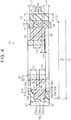
FIG. 2 is a sectional view illustrating a schematic configuration of a worm wheel of a worm speed reducer in an assist mechanism in terms of the electric power steering system; -
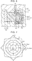
FIG. 3 is a perspective view illustrating a schematic configuration of a sleeve of the worm wheel; -
FIG. 4 is a sectional view illustrating a schematic configuration of the worm wheel when viewed from an arrow-A direction inFIG. 2 ; -
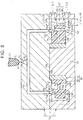
FIG. 5 is a sectional view to describe a manufacturing method for the worm wheel; -
FIG. 6 is a view illustrating a state where resin flows in terms of the manufacturing method for the worm wheel; and -
FIG. 7 is a view to describe roundness of a toothed portion in terms of the worm wheel. - One embodiment of a worm wheel and an electric power steering system will be described below. As illustrated in
FIG. 1 , for example, a vehicle is provided with an electric power steering system (hereinafter referred to as the "EPS") 1 configured to apply an assist force to asteering mechanism 2 as a steering force to steer steeredwheels 15. TheEPS 1 gives the assist force in response to a steering operation of a user so as to assist the steering operation of the user. - The
EPS 1 includes thesteering mechanism 2 and anassist mechanism 3. Thesteering mechanism 2 includes asteering wheel 10, a steering shaft 11, arack shaft 12, a rack-and-pinion mechanism 13,tie rods 14, and the steeredwheels 15. - The steering shaft 11 includes a
column shaft 11 a, anintermediate shaft 11b, and apinion shaft 11c. Thecolumn shaft 11a is connected to thesteering wheel 10. Theintermediate shaft 11b is connected to a lower end of thecolumn shaft 11a. Thepinion shaft 11c is connected to a lower end of theintermediate shaft 11b. Therack shaft 12 is connected to a lower end of thepinion shaft 11c via the rack-and-pinion mechanism 13. - Hereby, the steering shaft 11 rotates in conjunction with the
steering wheel 10. A rotational motion of the steering shaft 11 is converted into a reciprocating linear motion of therack shaft 12 in an axial direction (a right-left direction ofFIG. 1 ) via the rack-and-pinion mechanism 13 connecting thepinion shaft 11c to therack shaft 12. The reciprocating linear motion is transmitted to right and left steeredwheels 15 via thetie rods 14 connected to both ends of therack shaft 12, so that a steered angle of the steeredwheels 15 is changed. - The
assist mechanism 3 includes amotor 20 and aworm deceleration mechanism 22. Themotor 20 includes arotating shaft 21 configured to output a rotational force for rotation. For example, themotor 20 is a three-phase brushless motor that rotates based on a three-phase (U, V, W) driving electric power. - The
worm deceleration mechanism 22 includes aworm shaft 23 and aworm wheel 24. Theworm shaft 23 is connected to a tip end of therotating shaft 21 of themotor 20. Theworm wheel 24 is engaged with a worm of theworm shaft 23. Further, theworm wheel 24 is connected to thecolumn shaft 11a of the steering shaft 11 in an integrally rotatable manner. - Hereby, a rotational force of the
rotating shaft 21 of themotor 20 is transmitted to thecolumn shaft 11a, and further to therack shaft 12 via theworm shaft 23 and the worm wheel 24 (the worm deceleration mechanism 22). As such, theassist mechanism 3 converts the rotational force of therotating shaft 21 of themotor 20 into a force to cause therack shaft 12 to linearly reciprocate in the axial direction, via theworm deceleration mechanism 22. An axial force to be given to therack shaft 12 becomes an assist force, so as to assist the steering operation of the user. - Note that a
steering ECU 30 is connected to themotor 20. The steeringECU 30 controls driving (rotation) of themotor 20 based on detection results of various sensors provided in the vehicle. The various sensors include atorque sensor 40, a rotation angle sensor 41, and avehicle speed sensor 42. Thetorque sensor 40 is provided in thecolumn shaft 11 a. Thetorque sensor 40 detects a torque value Th, which is value indicative of a magnitude and a direction of a steering torque, which is a load applied to the steering shaft 11 by the steering operation of the user. The rotation angle sensor 41 is provided in themotor 20. The rotation angle sensor 41 detects a motor angle θm of therotating shaft 21 of themotor 20. Thevehicle speed sensor 42 detects a vehicle speed value V, which is a vehicle running speed. - The steering
ECU 30 sets a target assist torque (an assist force) based on the detection results of the sensors, and controls a current to be supplied to themotor 20 so that an actual assist torque reaches the target assist torque. - Next will be described the configuration of the
worm wheel 24 of theworm deceleration mechanism 22 in detail. As illustrated inFIG. 2 , theworm wheel 24 includes asleeve 50 and atoothed portion 60. - The
sleeve 50 includes aboss 51 and anannular portion 52. Theboss 51 is made of a metallic material such as stainless steel. Theboss 51 has a cylindrical shape. Theboss 51 is fitted to an outer peripheral surface of thecolumn shaft 11a of the steering shaft 11 by press-fitting or the like. Theannular portion 52 is made of a resin material such as synthetic resin. Theannular portion 52 has a cylindrical shape. Theannular portion 52 includes a firstannular portion 53, which is a part having an axial length (thickness) longer than the other parts, and a secondannular portion 54, which is a part having an axial length (thickness) smaller than the firstannular portion 53. Theannular portion 52 is integrated with theboss 51 by injection molding so as to cover a most axial part of an outer peripheral surface of theboss 51 in a radial direction. - The
toothed portion 60 is made of a resin material such as synthetic resin. Thetoothed portion 60 has a cylindrical shape. A plurality ofteeth 62 each having a tooth flank serving as a surface meshing with the worm of theworm shaft 23 is provided on an outerperipheral surface 61, which is a surface of thetoothed portion 60 in the radial direction. Note that the outerperipheral surface 61 is constituted by vertexes of theteeth 62. Thetoothed portion 60 is integrated with thesleeve 50 by injection molding so as to cover the secondannular portion 54 in theannular portion 52, which is a part of thesleeve 50, from the axial direction and the radial direction. - Next will be described a configuration of the
sleeve 50 further in detail. As illustrated inFIG. 2, FIG. 3 , and,FIG. 4 , which is a view seen from an arrow-A direction inFIG. 2 , the firstannular portion 53 includes a plurality of recessedportions sleeve 50. Each of the recessedportions 55 is opened on afirst side face 53a, which is a surface on one side (an upper side in each figure) of the firstannular portion 53 in the axial direction, and has a depth in the axial direction. Each of the recessedportions 56 is opened on asecond side face 53b, which is a surface on a side (a lower side in each figure) opposite to thefirst side face 53a of the firstannular portion 53 in the axial direction, and has a depth in the axial direction. The recessedportions portions portions FIG. 4 ), which is a length from an opening of the recessedportion 55 to a bottom thereof and a depth (L2 inFIG. 4 ), which is a length from an opening of the recessedportion 56 to a bottom thereof are set to the same magnitude (L1 = L2). - Note that, between the recessed
portions 55 adjacent to each other in the circumferential direction, aninner rib 55a is defined by circumferential walls of the recessedportions 55. The same can be said about the recessedportions 56. Respectiveinner ribs sleeve 50. - Similarly, as illustrated in
FIGS. 2, 3 , and4 , the secondannular portion 54 has a plurality of engagingholes sleeve 50. Each of the engagingholes 57 is opened on afirst side face 54a, which is a surface on one side (an upper side in each figure) of the secondannular portion 54 in the axial direction, and has a depth in the axial direction. Each of the engagingholes 58 is opened on asecond side face 54b, which is a surface on a side (a lower side in each figure) opposite to thefirst side face 54a of the secondannular portion 54 in the axial direction, and has a depth in the axial direction. The engagingholes holes holes holes FIG. 4 ), which is a length of the engaginghole 58 provided on thesecond side face 54b from an opening thereof to a bottom thereof is set to be smaller than a depth (L3 inFIG. 4 ), which is a length of the engaginghole 57 provided on thefirst side face 54a from an opening thereof to a bottom thereof (L3 > L4). - Note that, between the engaging
holes 57 adjacent to each other in the circumferential direction, anouter rib 57a is defined by respective walls of the engagingholes 57 in the circumferential direction. The same can be said about the engaging holes 58. Respectiveouter ribs sleeve 50. - Further, as illustrated in
FIG. 3 , theinner ribs 55a of the firstannular portion 53 and theouter ribs 57a of the secondannular portion 54 are configured such that their phases (circumferential positions) in the circumferential direction are different from each other. More specifically, theinner ribs 55a and theouter ribs 57a are configured so as to be displaced from each other in the circumferential direction by an angle θa on the basis of an axial center m of thesleeve 50. Hereby, theinner ribs 55a are placed with respect to theouter ribs 57a such that each of theinner ribs 55a is placed between its adjacentouter ribs 57a. Further, theouter ribs 57a are placed with respect to theinner ribs 55a such that each of theouter ribs 57a is placed between its adjacentinner ribs 55a. The same can be said about theinner ribs 56a and theouter ribs 58a. - Here, a configuration of the second
annular portion 54 is described further in detail with a configuration of thetoothed portion 60. As illustrated inFIGS. 2, 3 , and4 , the side faces 54a, 54b of the secondannular portion 54 are provided flat with respect to a direction perpendicular to the axial direction of thesleeve 50. A central part 54cc, in the axial direction, of an outerperipheral surface 54c of the secondannular portion 54 radially projects relative to both ends 54ca, 54cb thereof in the axial direction. That is, a diameter (L5 inFIG. 4 ) of the central part 54cc of the secondannular portion 54 is set to be larger than a diameter of the both ends 54ca, 54cb (L6 inFIG. 4 ) (L5 > L6). Hereby, a section of the secondannular portion 54 in the arrow-A direction has a trapezoidal shape projecting radially outside thesleeve 50. - Note that the both ends 54ca, 54cb of the second
annular portion 54 have an inclined surface that is inclined relative to the axial direction. The inclined surfaces of the both ends 54ca, 54cb are provided flat with respect to the circumferential direction. The central part 54cc of the secondannular portion 54 has a flat surface that is flat with respect to the axial direction. The flat surface of the central part 54cc is also provided flat with respect to the circumferential direction. - The
toothed portion 60 includes a firstthick portion 63, a secondthick portion 64, and atooth forming portion 65. The firstthick portion 63 is provided on thefirst side face 54a (an upper side inFIG. 4 ) of the secondannular portion 54, on which the engagingholes 57 with a large depth are provided. That is, thefirst side face 54a is a part opposed to the firstthick portion 63. The secondthick portion 64 is provided on thesecond side face 54b (a lower side inFIG. 4 ) of the secondannular portion 54, on which the engagingholes 58 with a small depth are provided. That is, thesecond side face 54b is a part opposed to the secondthick portion 64. A thickness (L7 inFIG. 4 ) of the firstthick portion 63 in the axial direction is set to be smaller than a thickness (L8 inFIG. 4 ) of the secondthick portion 64 in the axial direction (L7 < L8). - The
tooth forming portion 65 is provided on the outerperipheral surface 54c (on right and left sides inFIG. 4 ) of the secondannular portion 54. The outerperipheral surface 61 of thetoothed portion 60, as a surface of thetooth forming portion 65, has a flat surface flush with thesleeve 50, namely, the axial direction of theworm wheel 24. The flat surface of thetooth forming portion 65 is provided also flat with respect to the circumferential direction. - Hereby, in the
tooth forming portion 65, a toothcentral part 65c provided on the central part 54cc of the outerperipheral surface 54c of the secondannular portion 54 is set to have a small thickness in the radial direction in comparison withtooth end parts peripheral surface 54c of the secondannular portion 54, as much as the outerperipheral surface 54c of the secondannular portion 54 projects radially outward. That is, a thickness (L9), in the radial direction, of the toothcentral part 65c of thetooth forming portion 65 is set to be smaller than a thickness (L10) of thetooth end parts - Further, the
thick portions protrusions protrusions 67 extend from the firstthick portion 63 toward thefirst side face 54a of the secondannular portion 54, to which the engagingprotrusions 67 are opposed. The engagingprotrusion 67 is opposed to the engaginghole 57 provided in the secondannular portion 54. That is, similarly to the engagingholes 57, the engagingprotrusions 67 are provided at regular intervals in the circumferential direction. The same can be also said about the engagingprotrusions 68 provided in the secondthick portion 64. The engagingprotrusions holes holes - Hereby, a whirl-stop function to restrict a relative rotation of the
toothed portion 60 to thesleeve 50 is applied to theworm wheel 24 through the engagement between the engagingholes protrusions thick portions - Next will be described a manufacturing method of the
worm wheel 24. As illustrated inFIG. 5 , theworm wheel 24 is manufactured such that aresin material 80 melted by a heater or the like is injected into adie 70, so that thetoothed portion 60 is injection-molded integrally with thesleeve 50. - The
die 70 includes acavity 71 and acore 72. Thecavity 71 and the core 72 are made of a metallic material such as steel. Thecavity 71 and the core 72 are separated from each other at a parting line PL. The parting line PL is provided so as to have a rugged shape between thecavity 71 and thecore 72. - The
cavity 71 includes amold portion 73 and amold fixing base 74. Themold portion 73 is an internal space provided by cutting an inner part of thecavity 71. Themold portion 73 has anopening 73a opened on a side opposed to thecore 72 of thecavity 71. Themold portion 73 is modelled to mold thetoothed portion 60 such that theopening 73a is closed by the core 72 in a state where thesleeve 50 is placed inside thecavity 71. - The
mold fixing base 74 includes abase portion 74a and a fixedportion 74b. Thebase portion 74a has a discoidal shape. Thebase portion 74a projects toward theopening 73a from a center of a bottom 73b opposed to theopening 73a of themold portion 73. Thebase portion 74a is used to place thesleeve 50 inside thecavity 71. The fixedportion 74b has a columnar shape. The fixedportion 74b projects toward theopening 73a from a center of a part of thebase portion 74a on a side opposed to theopening 73a. The fixedportion 74b is fitted to theboss 51 of thesleeve 50 so as to position and fix thesleeve 50 inside thecavity 71. - The
core 72 includes anozzle arrangement portion 75, asprue 76, a runner 77, and agate 78. Thenozzle arrangement portion 75 is opened on an opposite side of the core 72 to a side opposed to thecavity 71. Anozzle 91 of aninjector 90 for injecting theresin material 80 is placed in thenozzle arrangement portion 75. Thesprue 76 is a tubular passage. Thesprue 76 extends from thenozzle arrangement portion 75 toward thecavity 71. The runner 77 is a cylindrical passage. The runner 77 expands in a circular shape (a radial shape) from thesprue 76 along the parting line PL, and then extends toward thecavity 71. That is, thesprue 76 is a passage that connects thenozzle arrangement portion 75 to the runner 77. Thegate 78 is a tubular passage. Thegate 78 extends in a tapered shape from the runner 77 toward thecavity 71, so as to communicate with themold portion 73 of thecavity 71. - Further, the
core 72 includes amale die portion 72a. In a case where theopening 73a is closed by the core 72 in a state where thesleeve 50 is placed inside thecavity 71, themale die portion 72a closes the openings of the recessedportions 55 provided on thefirst side face 53a of the firstannular portion 53. Note that the openings of the recessedportions 56 provided on thesecond side face 53b of the firstannular portion 53 are closed by thebase portion 74a of themold fixing base 74. Hereby, themale die portion 72a and thebase portion 74a restrict theresin material 80 from entering the recessedportions annular portion 53. In this regard, themold portion 73 communicates with the engagingholes annular portion 54, so as to allow theresin material 80 to enter the engagingholes - As illustrated in
FIG. 5 , thesleeve 50 is placed inside thecavity 71, that is, in themold portion 73, so that thefirst side face 54a of the secondannular portion 54 is opposed to thegate 78. In this case, thefirst side face 54a of the secondannular portion 54 is placed on a side closer to thegate 78 relative to thesecond side face 54b. - When the
opening 73a is closed by the core 72 in a state where thesleeve 50 is placed as such, a first thick mold portion 63' corresponding to the firstthick portion 63 of thetoothed portion 60 is formed between thefirst side face 54a of the secondannular portion 54 and an inner peripheral surface, of themold portion 73, opposed to thefirst side face 54a. Further, a second thick mold portion 64' corresponding to the secondthick portion 64 of thetoothed portion 60 is formed between thesecond side face 54b of the secondannular portion 54 and an inner peripheral surface, of themold portion 73, opposed to thesecond side face 54b. A tooth mold portion 65' corresponding to thetooth forming portion 65 of thetoothed portion 60 is formed between the outerperipheral surface 54c of the secondannular portion 54 and an inner peripheral surface, of themold portion 73, opposed to the outerperipheral surface 54c. - Note that, in the present embodiment, the first thick mold portion 63' is placed on a side closer to the
gate 78 relative to the second thick mold portion 64'. Hereby, the firstthick portion 63 corresponding to the first thick mold portion 63' is molded on the side closer to thegate 78 relative to the secondthick portion 64 corresponding to the second thick mold portion 64'. - In the axial direction of the
sleeve 50, an interval (L11 inFIG. 5 ) of the first thick mold portion 63' is set to be smaller than an interval (L12 inFIG. 5 ) of the second thick mold portion 64' (L11 < L12). Note that the interval L11 is the same as the thickness L7 inFIG. 4 and the interval L12 is the same as the thickness L8 inFIG. 4 . - In the radial direction of the
sleeve 50, an interval (L13 inFIG. 5 ) of a toothcenter mold portion 65c', of the tooth mold portion 65', corresponding to the toothcentral part 65c is set to be smaller than an interval (L14 inFIG. 5 ) of both toothend mold portions 65a', 65b', of the tooth mold portion 65', corresponding to thetooth end parts FIG. 4 and the interval L14 is the same as the thickness L10 inFIG. 4 . - Subsequently, after the
sleeve 50 is placed in themold portion 73 and a pressure is applied to perform clamping in a state where theopening 73a is closed by thecore 72, theresin material 80 is injected to be supplied into the thick mold portions 63', 64' of themold portion 73 and the tooth mold portion 65' from theinjector 90 through thegate 78. - As illustrated in an enlarged view of
FIG. 6 , theresin material 80 passes through between themale die portion 72a of thecore 72 and theopening 73a of thecavity 71 from the core-72 side so as to be supplied by injection into thewhole mold portion 73. The second thick mold portion 64', the tooth mold portion 65', and the first thick mold portion 63' are supplied with theresin material 80 in this order, and theresin material 80 is cooled off through the contact with the inner peripheral surface of themold portion 73 so as to shrink and solidify in the order of supplying. In this case, theresin material 80 is supplied into the engaginghole 57 on the first thick mold portion 63' side and also supplied into the engaginghole 58 on the second thick mold portion 64' side between the engagingholes resin material 80 supplied into the engaginghole 57 on the first thick mold portion 63' side and theresin material 80 supplied into the engaginghole 58 on the second thick mold portion 64' side through the outerperipheral surface 54c side of the engaginghole 57 are supplied without forming a joining part on the outerperipheral surface 54c side. - The
resin material 80 shrinks and solidifies from the second thick mold portion 64' along a periphery of the inner peripheral surface of themold portion 73, and finally, theresin material 80 shrinks and solidifies in a part of the tooth mold portion 65' around the secondannular portion 54, the part being relatively distanced from the inner peripheral surface of themold portion 73. That is, particularly the toothcenter mold portion 65c' of the tooth mold portion 65' solidifies later than the other parts, i.e., thetooth end parts - After that, a unified product in which the
toothed portion 60 is integrated with thesleeve 50 by injection molding is taken out of the die 70 (thecavity 71 and the core 72), and thus, theworm wheel 24 is finished. - Note that, in
FIG. 7 in which theworm wheel 24 is illustrated in a simplified manner, theinner ribs outer ribs FIG. 7 ) virtually indicating changes of irregularities of the outer peripheral surface 61 (indicated by a bold line inFIG. 7 ) of thetoothed portion 60 with respect to the circumferential direction exhibits changes that project only by generally the same amount in the radial direction at respective parts where theinner ribs outer ribs - In this regard, as illustrated in
FIG. 7 in which theinner ribs inner ribs outer ribs FIG. 7 ) virtually indicating changes of irregularities of the outerperipheral surface 61 of thetoothed portion 60 with respect to the circumferential direction exhibits such a change that parts where theinner ribs outer ribs inner ribs outer ribs worm wheel 24 of the present embodiment is improved in flatness with respect to the circumferential direction of the outerperipheral surface 61 of thetoothed portion 60, that is, accuracy in so-called roundness. - With the present embodiment described above, it is possible to obtain the following operation/working-effects. With the manufacturing method of the worm wheel of the present embodiment, it is possible to manufacture the
worm wheel 24 which restrains the toothcentral part 65c of thetooth forming portion 65, in the outerperipheral surface 61 of thetoothed portion 60, from being recessed in comparison with thetooth end parts thick portion 63 side, in the outerperipheral surface 61 of thetoothed portion 60, from being recessed in comparison with a part on the secondthick portion 64 side. In theworm wheel 24 manufactured as such, a decrease in accuracy of flatness of thetooth forming portion 65, that is, the outerperipheral surface 61 of thetoothed portion 60 with respect to the axial direction is restrained. - More specifically, as illustrated in
FIG. 4 , in theworm wheel 24 of the present embodiment, the thickness (L9), in the radial direction, of the toothcentral part 65c of thetooth forming portion 65 is set to be smaller than the thickness (L10) of thetooth end parts - Accordingly, as illustrated in
FIG. 5 , in a shrinkage course at the time when theresin material 80 supplied in the tooth mold portion 65' of the die 70 solidifies, it is possible to reduce a sink amount of the toothcenter mold portion 65c' to be pulled toward thesleeve 50 side in comparison with the teeth endmold portions 65a', 65b', the toothcenter mold portion 65c' solidifying later than the toothend mold portions 65a', 65b' of thedie 70. This is apparent from general findings that the sink amount is smaller as the thickness is smaller in injection molding. - Furthermore, as illustrated in
FIG. 4 , in theworm wheel 24 of the present embodiment, thethick portions thick portion 64, which is distanced from thegate 78 in comparison with the firstthick portion 63 molded on the side closer to thegate 78 at the time of injection molding, is larger than the thickness (L7) of the firstthick portion 63. - Accordingly, as illustrated in
FIG. 5 , in a course of supplying the resin into the thick mold portions 63', 64' of the die 70, the second thick mold portion 64', which is distanced from thegate 78 in comparison with the first thick mold portion 63', can have a larger resin amount of theresin material 80 to be supplied therein in comparison with the first thick mold portion 63' closer to thegate 78. As a result, as apparent from the general findings, since the second thick mold portion 64' of the die 70 has a large resin amount of theresin material 80 to be supplied therein in comparison with a part to become the first thick mold portion 63' of the die 70, the sink amount can be increased by just that much, thereby making it possible to decrease a difference in the sink amount between the thick mold portions 63', 64'. - As a result, it is possible to restrain the tooth
central part 65c of thetooth forming portion 65, in the outerperipheral surface 61 of thetoothed portion 60, from being recessed in comparison with thetooth end parts tooth end part 65a on the firstthick portion 63 side, in the outerperipheral surface 61 of thetoothed portion 60, from being recessed in comparison with thetooth end part 65b on the secondthick portion 64 side. Accordingly, it is possible to restrain a decrease in accuracy of flatness of thetooth forming portion 65, that is, the outerperipheral surface 61 of thetoothed portion 60 with respect to the axial direction. - The
worm wheel 24 has a whirl-stop function to restrict a relative rotation of thetoothed portion 60 to thesleeve 50. Note that constituents to add the whirl-stop function, that is, the engagingholes protrusions thick portions annular portion 54 of thesleeve 50. Accordingly, the outerperipheral surface 54c of the secondannular portion 54, which is the outer peripheral surface of thesleeve 50, can be formed as a flat surface that is flat with respect to the circumferential direction. Accordingly, even if the whirl-stop function is added, it is possible to restrain the decrease in accuracy of flatness of the outerperipheral surface 61 of thetoothed portion 60 with respect to the axial direction. - In the present embodiment, the thickness of the
tooth forming portion 65 in the radial direction is decreased from thetooth end parts central part 65c. That is, the thickness of thetooth forming portion 65 in the radial direction becomes smaller from the second thick mold portion 64' of the die 70, in which theresin material 80 supplied in thedie 70 solidifies early, toward the first thick mold portion 63' of the die 70, in which theresin material 80 solidifies later, at the time of injection molding of thetoothed portion 60. Accordingly, it is possible to more effectively restrain the toothcentral part 65c of thetooth forming portion 65, in the outerperipheral surface 61 of thetoothed portion 60, from being recessed in comparison with thetooth end parts peripheral surface 61 of thetoothed portion 60 with respect to the axial direction. - In the
worm wheel 24, the outerperipheral surface 54c of the secondannular portion 54 of thesleeve 50 is provided flat with respect to the circumferential direction. Accordingly, similarly to the above, it is possible to more effectively restrain the outerperipheral surface 61 of thetoothed portion 60 from changing irregularly and it is possible to more appropriately restrain the decrease in accuracy of flatness of the outerperipheral surface 61 of thetoothed portion 60 with respect to the axial direction. - In the manufacturing method of the worm wheel of the present embodiment, even if the
toothed portion 60 is injection-molded, it is possible to restrain the decrease in accuracy of flatness of the outerperipheral surface 61 of thetoothed portion 60 with respect to the circumferential direction and it is possible to manufacture theworm wheel 24 without a weld line on the outerperipheral surface 54c side of the engagingholes worm wheel 24 manufactured as such, the decrease in accuracy of flatness of the outerperipheral surface 61 of thetoothed portion 60 with respect to the circumferential direction is restrained and a decrease in strength and durability is also restrained. - More specifically, as illustrated in
FIG. 4 , theworm wheel 24 of the present embodiment has a whirl-stop function to restrict a relative rotation of thetoothed portion 60 to thesleeve 50. The constituents to add the whirl-stop function, that is, the engagingholes protrusions thick portions peripheral surface 54c of the secondannular portion 54 of thesleeve 50, but on the side faces 54a, 54b thereof, thereby making it possible to maintain flatness of the outerperipheral surface 54c of the secondannular portion 54 with respect to the circumferential direction. Furthermore, as illustrated in the figure, in theworm wheel 24 of the present embodiment, the engaginghole 57 of the secondannular portion 54 is not a through-hole, but a hole (bottomed hole) having a depth. - Hereby, even if the
toothed portion 60 is injection-molded, it is possible to restrain the decrease in accuracy of flatness of the outerperipheral surface 61 of thetoothed portion 60 with respect to the circumferential direction. Besides, in this case, theresin material 80 supplied into the engaginghole 57 of thesleeve 50 and theresin material 80 supplied into the engaginghole 58 through the outerperipheral surface 54c side of the engaginghole 57 are not joined on the outerperipheral surface 54c side, so that a weld line is not formed. Accordingly, it is possible to restrain the decrease in accuracy of flatness of the outerperipheral surface 61 of thetoothed portion 60 with respect to the circumferential direction and to restrain the decrease in strength and durability. - In the present embodiment, the constituents to add the whirl-stop function are provided on the side faces 54a, 54b of the second
annular portion 54 of thesleeve 50, thereby making it possible to more appropriately yield an effect to restrict a relative rotation of thetoothed portion 60 to thesleeve 50. Further, even in a case where the constituents to add the whirl-stop function are provided on the side faces 54a, 54b of the secondannular portion 54 as such, the engagingholes peripheral surface 54c of the secondannular portion 54, so that it is possible to maintain the flatness of the outerperipheral surface 54c of the secondannular portion 54 with respect to the circumferential direction. - In the
worm wheel 24, at the time of injection molding of thetoothed portion 60, the depth of the engaginghole 57 on thefirst side face 54a of the secondannular portion 54 is set to be larger than the depth of the engaginghole 58 on thesecond side face 54b of the secondannular portion 54. Accordingly, at the time of injection molding of thetoothed portion 60, a difference between a distance from thegate 78 to the bottom of the engaginghole 57 on thefirst side face 54a side of the secondannular portion 54 and a distance from thegate 78 to the bottom of the engaginghole 58 on thesecond side face 54b side of the secondannular portion 54 can be made small in comparison with a case where the engagingholes annular portion 54 have the same depth. Hereby, it is possible to reduce a difference in the cooling speed of the suppliedresin material 80 between the side faces 54a, 54b of the secondannular portion 54, thereby making it possible to decrease a difference in a sink amount between the side faces 54a, 54b. Accordingly, even if the whirl-stop function is added, it is possible to more appropriately restrain the decrease in accuracy of flatness of the outerperipheral surface 61 of thetoothed portion 60 with respect to the axial direction. - With the use of the
worm wheel 24 of the present embodiment, which restrains the decrease in accuracy of flatness of thetooth forming portion 65, that is, the outerperipheral surface 61 of thetoothed portion 60 with respect to the axial direction, which restrains the decrease in accuracy of flatness of the outerperipheral surface 61 of thetoothed portion 60 with respect to the circumferential direction, and which restrains the decrease in strength and durability, it is possible to achieve improvement of transfer efficiency at the time when an assist force generated by themotor 20 is transmitted to the steeredwheels 15. Accordingly, it is possible to achieve theEPS 1 that can improve reliability in application of the assist force. - Note that the above embodiment can be performed in the following manner. The flatness of the outer
peripheral surface 54c of the secondannular portion 54 with respect to the circumferential direction may be decreased as compared with the above embodiment, as long as it is possible to maintain the flatness of the outerperipheral surface 61 of thetoothed portion 60 with respect to the axial direction. - The both ends 54ca, 54cb may have a flat surface with respect to the axial direction, for example, provided that the central part 54cc radially projects relative to the both ends 54ca, 54cb in the outer
peripheral surface 54c of the secondannular portion 54. Further, in a case where the shapes of the both ends 54ca, 54cb are adjusted, it is possible to adjust increase and decrease in the resin amount of theresin material 80 to be supplied between the thick mold portions 63', 64'. In this case, without making a structural change to thecavity 71 of the die 70, it is possible to adjust the difference in the sink amount between the thick mold portions 63', 64'. - The depths (L3, L4) of the engaging
holes hole 57 in thefirst side face 54a may be set to be smaller than the depth (L4) of the engaginghole 58 in thesecond side face 54b (L4 > L3). - The whirl-stop function to restrict a relative rotation of the
toothed portion 60 to thesleeve 50 may be achieved by providing the engaging holes only in either one of the side faces 54a, 54b of the secondannular portion 54. Even in this case, it is possible to maintain the outerperipheral surface 54c of the secondannular portion 54, which is the outer peripheral surface of thesleeve 50, to be flat with respect to the circumferential direction, thereby making it possible to yield an effect to restrain the decrease in accuracy of flatness of the outerperipheral surface 61 of thetoothed portion 60 with respect to the axial direction. - The whirl-stop function to restrict a relative rotation of the
toothed portion 60 to thesleeve 50 may be achieved such that a plurality of ribs is provided instead of providing the engagingholes annular portion 54 and the plurality of ribs is buried in thetoothed portion 60. - In the present embodiment, if a relative rotation of the
toothed portion 60 to thesleeve 50 can be restricted by a bonding force of integration by injection molding, the configurations of the engagingholes protrusions portions annular portion 53 may be used as the whirl-stop function. - The
gate 78 may be placed on thesecond side face 54b side of the secondannular portion 54. Further, if thegate 78 is placed on either of the side faces 54a, 54b of the secondannular portion 54, thegate 78 may be displaced to the outerperipheral surface 54c side or to the firstannular portion 53 side or may be changed so that an injection direction of theresin material 80 becomes the radial direction. - The
annular portion 52 may be made of a metallic material such as stainless steel. In this case, theboss 51 and theannular portion 52 may be integrated. Theworm wheel 24 can be applied to a machine tool or the like, for example, as a device other than the electric power steering system, provided that the device includes theworm deceleration mechanism 22. - The embodiment embodies the invention in the form of the column-
type EPS 1, but is not limited to this. For example, the invention may be embodied in the form of a rack-type EPS that applies an assist force to therack shaft 12 via a rack-and-pinion mechanism provided separately from the rack-and-pinion mechanism 13. Further, the invention may be applied to a steer-by-wire (SBW) steering apparatus. Further, the invention is not limited to the steer-by-wire system, and may be embodied in the form of a rear wheel steering system and a four-wheel steering system (4WS).
Claims (9)
- A worm wheel characterized by comprising:a sleeve (50) having an annular shape; anda toothed portion (60) provided by injection molding so as to cover a part of the sleeve (50), the toothed portion (60) including a tooth forming portion (65) provided on an outer peripheral surface, which is a surface of the sleeve (50) in a radial direction, a first thick portion (63) provided on a first side face (54a), which is a surface of the sleeve (50) on a side closer to an injection-mold gate in an axial direction, and a second thick portion (64) provided on a second side face (54b), which is a surface of the sleeve (50) on an opposite side to the first side face (54a) in the axial direction, wherein:a central part (54cc), in the axial direction, of the outer peripheral surface (54c) of the sleeve (50) projects in the radial direction relative to both ends (54ca, 54cb) in the axial direction; andthe first thick portion (63) of the toothed portion (60) has a smaller thickness in the axial direction than the second thick portion (64).
- The worm wheel according to claim 1, wherein
a diameter of the outer peripheral surface (54c) of the sleeve (50) increases from the both ends (54ca, 54cb) toward the central part (54cc). - The worm wheel according to claim 1 or 2, wherein
the outer peripheral surface (54c) of the sleeve (50) is provided flat with respect to a circumferential direction. - The worm wheel according to any one of claims 1 to 3, wherein:the sleeve (50) has an engaging hole (57, 58) having a depth in the axial direction and provided in a part of at least one of the first side face (54a) and the second side face (54b), the part being opposed to the thick portion of the toothed portion (60); andthe thick portion opposed to the side face having the engaging hole (57, 58), out of the first thick portion (63) and the second thick portion (64), engages with the engaging hole (57, 58).
- The worm wheel according to claim 4, wherein:the sleeve (50) has respective engaging holes (57, 58) having a depth in the axial direction and provided in respective parts of both the first side face (54a) and the second side face (54b), the respective parts being opposed to the first thick portion (63) and the second thick portion (64) of the toothed portion (60); andthe first thick portion (63) and the second thick portion (64) engage with the respective engaging holes (57, 58).
- The worm wheel according to claim 5, wherein:the engaging hole (58) provided on the second side face (54b) has a smaller depth in the axial direction than the engaging hole (57) provided on the first side face (54a).
- An electric power steering system characterized by comprising:the worm wheel (24) according to any one of claims 1 to 6; anda motor (20) configured to generate a steering force to steer steered wheels (15) of a steering mechanism (2), wherein:the worm wheel (24) mechanically connects the steering mechanism (2) to the motor (20) so as to transmit the steering force generated by the motor (20) to the steered wheels (15); andthe steered wheels (15) are steered when the steering force generated by the motor (20) is transmitted to the steered wheels (15).
- A manufacturing method for a worm wheel obtained such that a toothed portion is injection-molded so as to cover a part of a sleeve having an annular shape, the toothed portion including a tooth forming portion on an outer peripheral surface, which is a surface of the sleeve in a radial direction, a first thick portion on a first side face, which is one surface of the sleeve in an axial direction, and a second thick portion on a second side face, which is a surface of the sleeve on an opposite side to the first side face in the axial direction, the manufacturing method characterized by comprising:placing the sleeve (50) in a die (70) so that a gate from which resin is injected is positioned on a side closer to the first side face (54a) of the sleeve (50), wherein a central part (54cc), in the axial direction, of the outer peripheral surface (54c) of the sleeve (50) projects in the radial direction relative to both ends (54ca, 54cb) in the axial direction, and an axial interval between the first side face (54a) of the sleeve (50) and an inner surface of the die (70), the inner surface being opposed to the first side face (54a) is smaller than an axial interval between the second side face (54b) of the sleeve (50) on an opposite side to the first side face (54a) and an inner surface of the die (70), the inner surface being opposed to the second side face (54b); andsupplying the resin into the die (70) in a state where the sleeve (50) is placed inside the die (70).
- The manufacturing method according to claim 8, wherein:the supplying is performed on an engaging hole of the sleeve (50);the outer peripheral surface (54c) of the sleeve (50) is provided flat with respect to a circumferential direction; andthe sleeve (50) has the engaging hole (57, 58) having a depth in the axial direction and provided in a part opposed to the thick portion of the toothed portion (60), the thick portion being opposed to at least one of the first side face (54a) and the second side face (54b).
Applications Claiming Priority (2)
| Application Number | Priority Date | Filing Date | Title |
|---|---|---|---|
| JP2016139341A JP2018009657A (en) | 2016-07-14 | 2016-07-14 | Worm wheel, electric power steering device and manufacturing method of worm wheel |
| JP2016139340A JP6729113B2 (en) | 2016-07-14 | 2016-07-14 | Worm wheel, electric power steering device, and method for manufacturing worm wheel |
Publications (3)
| Publication Number | Publication Date |
|---|---|
| EP3270008A2 true EP3270008A2 (en) | 2018-01-17 |
| EP3270008A3 EP3270008A3 (en) | 2018-02-28 |
| EP3270008B1 EP3270008B1 (en) | 2020-11-25 |
Family
ID=59325219
Family Applications (1)
| Application Number | Title | Priority Date | Filing Date |
|---|---|---|---|
| EP17180996.5A Not-in-force EP3270008B1 (en) | 2016-07-14 | 2017-07-12 | Worm wheel, electric power steering system, and manufacturing method for worm wheel |
Country Status (3)
| Country | Link |
|---|---|
| US (1) | US10724620B2 (en) |
| EP (1) | EP3270008B1 (en) |
| CN (1) | CN107620782B (en) |
Families Citing this family (12)
| Publication number | Priority date | Publication date | Assignee | Title |
|---|---|---|---|---|
| JP6632921B2 (en) * | 2016-03-23 | 2020-01-22 | 株式会社エンプラス | Resin gear, resin gear injection molding method, resin toothed belt pulley, and resin rotating body |
| KR102645000B1 (en) | 2019-03-08 | 2024-03-08 | 에이치엘만도 주식회사 | Steer-by-wire Type Steering Apparatus |
| FR3100150B1 (en) * | 2019-08-29 | 2021-08-13 | Jtekt Europe Sas | Method of manufacturing a reducer wheel by overmolding |
| JP7339076B2 (en) * | 2019-08-30 | 2023-09-05 | ファナック株式会社 | Lightweight gear and its manufacturing method, gear train manufacturing method and robot |
| KR102670455B1 (en) * | 2019-09-03 | 2024-05-29 | 에이치엘만도 주식회사 | Worm Wheel of Reducer for Steering Apparatus and Manufacturing Method of The Same |
| EP3789635B1 (en) * | 2019-09-03 | 2022-06-01 | IMS Gear SE & Co. KGaA | Gearwheel |
| EP3800375B1 (en) * | 2019-10-01 | 2023-02-15 | IMS Gear SE & Co. KGaA | Gear crane support part for a two-component or multi-component toothed wheel and two-component or multi-component toothed wheel with such a tooth-crane support part |
| US12607255B2 (en) | 2020-07-07 | 2026-04-21 | Nsk Ltd. | Method for producing worm wheel, and worm wheel |
| JP7508997B2 (en) * | 2020-11-04 | 2024-07-02 | 株式会社プロテリアル | Resin-sealed electronic component and its manufacturing method |
| WO2022266147A1 (en) | 2021-06-14 | 2022-12-22 | Reell Precision Manufacturing Corporation | Molded housing friction device having stable torque over temperature range |
| WO2022264376A1 (en) * | 2021-06-17 | 2022-12-22 | 株式会社ジェイテクト | Gear and steering device |
| CN113446378B (en) * | 2021-07-21 | 2022-09-13 | 浙江汇丰汽车零部件股份有限公司 | Gear structure of steering engine and preparation method thereof |
Citations (2)
| Publication number | Priority date | Publication date | Assignee | Title |
|---|---|---|---|---|
| JP2010014253A (en) | 2008-07-07 | 2010-01-21 | Nsk Ltd | Steering auxiliary gear for electric power steering device |
| JP2015155757A (en) | 2009-03-17 | 2015-08-27 | クワドラント エーペーペー アクチェンゲゼルシャフトQuadrant Epp Ag | Composite gear blank and method for manufacturing the same |
Family Cites Families (7)
| Publication number | Priority date | Publication date | Assignee | Title |
|---|---|---|---|---|
| KR0137782B1 (en) | 1993-12-07 | 1998-06-01 | 쭈보이 우주히꼬 | Power steering apparatus |
| JP4482802B2 (en) | 2004-07-07 | 2010-06-16 | 株式会社ジェイテクト | Worm wheel and electric power steering device |
| DE102006030097B3 (en) | 2006-06-28 | 2008-02-14 | Zf Friedrichshafen Ag | screw gear |
| JP4944941B2 (en) * | 2009-12-21 | 2012-06-06 | 日立オートモティブシステムズ株式会社 | Worm wheel |
| JP2011202682A (en) * | 2010-03-24 | 2011-10-13 | Jtekt Corp | Gear |
| JP2015113967A (en) | 2013-12-16 | 2015-06-22 | 日本電産株式会社 | Motor and method for manufacturing gear used in the motor |
| JP6523631B2 (en) * | 2014-08-12 | 2019-06-05 | Ntn株式会社 | Gear and electric actuator provided with the same |
-
2017
- 2017-07-11 US US15/646,197 patent/US10724620B2/en not_active Expired - Fee Related
- 2017-07-12 EP EP17180996.5A patent/EP3270008B1/en not_active Not-in-force
- 2017-07-12 CN CN201710565523.4A patent/CN107620782B/en not_active Expired - Fee Related
Patent Citations (2)
| Publication number | Priority date | Publication date | Assignee | Title |
|---|---|---|---|---|
| JP2010014253A (en) | 2008-07-07 | 2010-01-21 | Nsk Ltd | Steering auxiliary gear for electric power steering device |
| JP2015155757A (en) | 2009-03-17 | 2015-08-27 | クワドラント エーペーペー アクチェンゲゼルシャフトQuadrant Epp Ag | Composite gear blank and method for manufacturing the same |
Also Published As
| Publication number | Publication date |
|---|---|
| US20180017149A1 (en) | 2018-01-18 |
| EP3270008A3 (en) | 2018-02-28 |
| CN107620782A (en) | 2018-01-23 |
| US10724620B2 (en) | 2020-07-28 |
| EP3270008B1 (en) | 2020-11-25 |
| CN107620782B (en) | 2022-05-17 |
Similar Documents
| Publication | Publication Date | Title |
|---|---|---|
| EP3270008B1 (en) | Worm wheel, electric power steering system, and manufacturing method for worm wheel | |
| US20120111144A1 (en) | Gear | |
| US6497041B2 (en) | Method of producing resin gear | |
| EP1950122B1 (en) | Gear and electric power steering device | |
| US9707992B2 (en) | Worm wheel and electric power steering apparatus | |
| JP5310109B2 (en) | Brushless motor rotor, brushless motor, electric power steering apparatus, and method for manufacturing brushless motor rotor | |
| CN108698277B (en) | Method for producing a steering shaft of variable length and injection moulding device for carrying out the method | |
| CN108698276B (en) | Method for manufacturing a steering shaft of variable length and injection moulding device for carrying out the method | |
| JP2017082858A (en) | GEAR, GEAR MANUFACTURING METHOD, AND STEERING DEVICE | |
| KR101906716B1 (en) | Wormwheel for electronic steering | |
| JP6729113B2 (en) | Worm wheel, electric power steering device, and method for manufacturing worm wheel | |
| KR101798906B1 (en) | Worm wheel for motor driven power steering and manufacturing method thereof | |
| CN112728030B (en) | Ball screw nut, rotating unit and method for manufacturing ball screw nut | |
| CN221678813U (en) | Worm wheel of electric power steering device | |
| JP2018009657A (en) | Worm wheel, electric power steering device and manufacturing method of worm wheel | |
| JP2017082859A (en) | Gear and steering device | |
| JP7283319B2 (en) | Worm wheel unit and manufacturing method thereof, worm reduction gear | |
| JP2018020453A (en) | Insert molding method, insert molded product, torque detection device, and electric power steering device | |
| US12331821B2 (en) | Gear and steering device | |
| JP2012110913A (en) | Worm wheel, manufacturing method thereof, and electric power steering device | |
| KR101942878B1 (en) | Injection molding apparatus for Worm-wheel | |
| JP7645532B2 (en) | Worm wheel and manufacturing method thereof | |
| JP2017082860A (en) | Gear and steering device | |
| JP2016068652A (en) | Worm wheel for electric power steering device and manufacturing method of the same | |
| JP2004351989A (en) | Electric power steering device and manufacturing method of electric power steering device |
Legal Events
| Date | Code | Title | Description |
|---|---|---|---|
| PUAI | Public reference made under article 153(3) epc to a published international application that has entered the european phase |
Free format text: ORIGINAL CODE: 0009012 |
|
| STAA | Information on the status of an ep patent application or granted ep patent |
Free format text: STATUS: THE APPLICATION HAS BEEN PUBLISHED |
|
| AK | Designated contracting states |
Kind code of ref document: A2 Designated state(s): AL AT BE BG CH CY CZ DE DK EE ES FI FR GB GR HR HU IE IS IT LI LT LU LV MC MK MT NL NO PL PT RO RS SE SI SK SM TR |
|
| AX | Request for extension of the european patent |
Extension state: BA ME |
|
| PUAL | Search report despatched |
Free format text: ORIGINAL CODE: 0009013 |
|
| AK | Designated contracting states |
Kind code of ref document: A3 Designated state(s): AL AT BE BG CH CY CZ DE DK EE ES FI FR GB GR HR HU IE IS IT LI LT LU LV MC MK MT NL NO PL PT RO RS SE SI SK SM TR |
|
| AX | Request for extension of the european patent |
Extension state: BA ME |
|
| RIC1 | Information provided on ipc code assigned before grant |
Ipc: F16H 55/22 20060101AFI20180123BHEP |
|
| STAA | Information on the status of an ep patent application or granted ep patent |
Free format text: STATUS: REQUEST FOR EXAMINATION WAS MADE |
|
| 17P | Request for examination filed |
Effective date: 20180824 |
|
| RBV | Designated contracting states (corrected) |
Designated state(s): AL AT BE BG CH CY CZ DE DK EE ES FI FR GB GR HR HU IE IS IT LI LT LU LV MC MK MT NL NO PL PT RO RS SE SI SK SM TR |
|
| STAA | Information on the status of an ep patent application or granted ep patent |
Free format text: STATUS: EXAMINATION IS IN PROGRESS |
|
| 17Q | First examination report despatched |
Effective date: 20191107 |
|
| GRAP | Despatch of communication of intention to grant a patent |
Free format text: ORIGINAL CODE: EPIDOSNIGR1 |
|
| STAA | Information on the status of an ep patent application or granted ep patent |
Free format text: STATUS: GRANT OF PATENT IS INTENDED |
|
| INTG | Intention to grant announced |
Effective date: 20200709 |
|
| GRAS | Grant fee paid |
Free format text: ORIGINAL CODE: EPIDOSNIGR3 |
|
| GRAA | (expected) grant |
Free format text: ORIGINAL CODE: 0009210 |
|
| STAA | Information on the status of an ep patent application or granted ep patent |
Free format text: STATUS: THE PATENT HAS BEEN GRANTED |
|
| AK | Designated contracting states |
Kind code of ref document: B1 Designated state(s): AL AT BE BG CH CY CZ DE DK EE ES FI FR GB GR HR HU IE IS IT LI LT LU LV MC MK MT NL NO PL PT RO RS SE SI SK SM TR |
|
| REG | Reference to a national code |
Ref country code: GB Ref legal event code: FG4D |
|
| REG | Reference to a national code |
Ref country code: CH Ref legal event code: EP |
|
| REG | Reference to a national code |
Ref country code: DE Ref legal event code: R096 Ref document number: 602017028113 Country of ref document: DE |
|
| REG | Reference to a national code |
Ref country code: AT Ref legal event code: REF Ref document number: 1338704 Country of ref document: AT Kind code of ref document: T Effective date: 20201215 |
|
| REG | Reference to a national code |
Ref country code: IE Ref legal event code: FG4D |
|
| REG | Reference to a national code |
Ref country code: AT Ref legal event code: MK05 Ref document number: 1338704 Country of ref document: AT Kind code of ref document: T Effective date: 20201125 |
|
| REG | Reference to a national code |
Ref country code: NL Ref legal event code: MP Effective date: 20201125 |
|
| PG25 | Lapsed in a contracting state [announced via postgrant information from national office to epo] |
Ref country code: NO Free format text: LAPSE BECAUSE OF FAILURE TO SUBMIT A TRANSLATION OF THE DESCRIPTION OR TO PAY THE FEE WITHIN THE PRESCRIBED TIME-LIMIT Effective date: 20210225 Ref country code: PT Free format text: LAPSE BECAUSE OF FAILURE TO SUBMIT A TRANSLATION OF THE DESCRIPTION OR TO PAY THE FEE WITHIN THE PRESCRIBED TIME-LIMIT Effective date: 20210325 Ref country code: RS Free format text: LAPSE BECAUSE OF FAILURE TO SUBMIT A TRANSLATION OF THE DESCRIPTION OR TO PAY THE FEE WITHIN THE PRESCRIBED TIME-LIMIT Effective date: 20201125 Ref country code: GR Free format text: LAPSE BECAUSE OF FAILURE TO SUBMIT A TRANSLATION OF THE DESCRIPTION OR TO PAY THE FEE WITHIN THE PRESCRIBED TIME-LIMIT Effective date: 20210226 Ref country code: FI Free format text: LAPSE BECAUSE OF FAILURE TO SUBMIT A TRANSLATION OF THE DESCRIPTION OR TO PAY THE FEE WITHIN THE PRESCRIBED TIME-LIMIT Effective date: 20201125 |
|
| PG25 | Lapsed in a contracting state [announced via postgrant information from national office to epo] |
Ref country code: AT Free format text: LAPSE BECAUSE OF FAILURE TO SUBMIT A TRANSLATION OF THE DESCRIPTION OR TO PAY THE FEE WITHIN THE PRESCRIBED TIME-LIMIT Effective date: 20201125 Ref country code: LV Free format text: LAPSE BECAUSE OF FAILURE TO SUBMIT A TRANSLATION OF THE DESCRIPTION OR TO PAY THE FEE WITHIN THE PRESCRIBED TIME-LIMIT Effective date: 20201125 Ref country code: IS Free format text: LAPSE BECAUSE OF FAILURE TO SUBMIT A TRANSLATION OF THE DESCRIPTION OR TO PAY THE FEE WITHIN THE PRESCRIBED TIME-LIMIT Effective date: 20210325 Ref country code: PL Free format text: LAPSE BECAUSE OF FAILURE TO SUBMIT A TRANSLATION OF THE DESCRIPTION OR TO PAY THE FEE WITHIN THE PRESCRIBED TIME-LIMIT Effective date: 20201125 Ref country code: BG Free format text: LAPSE BECAUSE OF FAILURE TO SUBMIT A TRANSLATION OF THE DESCRIPTION OR TO PAY THE FEE WITHIN THE PRESCRIBED TIME-LIMIT Effective date: 20210225 Ref country code: SE Free format text: LAPSE BECAUSE OF FAILURE TO SUBMIT A TRANSLATION OF THE DESCRIPTION OR TO PAY THE FEE WITHIN THE PRESCRIBED TIME-LIMIT Effective date: 20201125 |
|
| REG | Reference to a national code |
Ref country code: LT Ref legal event code: MG9D |
|
| PG25 | Lapsed in a contracting state [announced via postgrant information from national office to epo] |
Ref country code: HR Free format text: LAPSE BECAUSE OF FAILURE TO SUBMIT A TRANSLATION OF THE DESCRIPTION OR TO PAY THE FEE WITHIN THE PRESCRIBED TIME-LIMIT Effective date: 20201125 |
|
| PG25 | Lapsed in a contracting state [announced via postgrant information from national office to epo] |
Ref country code: RO Free format text: LAPSE BECAUSE OF FAILURE TO SUBMIT A TRANSLATION OF THE DESCRIPTION OR TO PAY THE FEE WITHIN THE PRESCRIBED TIME-LIMIT Effective date: 20201125 Ref country code: SK Free format text: LAPSE BECAUSE OF FAILURE TO SUBMIT A TRANSLATION OF THE DESCRIPTION OR TO PAY THE FEE WITHIN THE PRESCRIBED TIME-LIMIT Effective date: 20201125 Ref country code: CZ Free format text: LAPSE BECAUSE OF FAILURE TO SUBMIT A TRANSLATION OF THE DESCRIPTION OR TO PAY THE FEE WITHIN THE PRESCRIBED TIME-LIMIT Effective date: 20201125 Ref country code: EE Free format text: LAPSE BECAUSE OF FAILURE TO SUBMIT A TRANSLATION OF THE DESCRIPTION OR TO PAY THE FEE WITHIN THE PRESCRIBED TIME-LIMIT Effective date: 20201125 Ref country code: LT Free format text: LAPSE BECAUSE OF FAILURE TO SUBMIT A TRANSLATION OF THE DESCRIPTION OR TO PAY THE FEE WITHIN THE PRESCRIBED TIME-LIMIT Effective date: 20201125 Ref country code: SM Free format text: LAPSE BECAUSE OF FAILURE TO SUBMIT A TRANSLATION OF THE DESCRIPTION OR TO PAY THE FEE WITHIN THE PRESCRIBED TIME-LIMIT Effective date: 20201125 |
|
| REG | Reference to a national code |
Ref country code: DE Ref legal event code: R097 Ref document number: 602017028113 Country of ref document: DE |
|
| PG25 | Lapsed in a contracting state [announced via postgrant information from national office to epo] |
Ref country code: DK Free format text: LAPSE BECAUSE OF FAILURE TO SUBMIT A TRANSLATION OF THE DESCRIPTION OR TO PAY THE FEE WITHIN THE PRESCRIBED TIME-LIMIT Effective date: 20201125 |
|
| PLBE | No opposition filed within time limit |
Free format text: ORIGINAL CODE: 0009261 |
|
| STAA | Information on the status of an ep patent application or granted ep patent |
Free format text: STATUS: NO OPPOSITION FILED WITHIN TIME LIMIT |
|
| PG25 | Lapsed in a contracting state [announced via postgrant information from national office to epo] |
Ref country code: IT Free format text: LAPSE BECAUSE OF FAILURE TO SUBMIT A TRANSLATION OF THE DESCRIPTION OR TO PAY THE FEE WITHIN THE PRESCRIBED TIME-LIMIT Effective date: 20201125 Ref country code: AL Free format text: LAPSE BECAUSE OF FAILURE TO SUBMIT A TRANSLATION OF THE DESCRIPTION OR TO PAY THE FEE WITHIN THE PRESCRIBED TIME-LIMIT Effective date: 20201125 Ref country code: NL Free format text: LAPSE BECAUSE OF FAILURE TO SUBMIT A TRANSLATION OF THE DESCRIPTION OR TO PAY THE FEE WITHIN THE PRESCRIBED TIME-LIMIT Effective date: 20201125 |
|
| 26N | No opposition filed |
Effective date: 20210826 |
|
| PG25 | Lapsed in a contracting state [announced via postgrant information from national office to epo] |
Ref country code: SI Free format text: LAPSE BECAUSE OF FAILURE TO SUBMIT A TRANSLATION OF THE DESCRIPTION OR TO PAY THE FEE WITHIN THE PRESCRIBED TIME-LIMIT Effective date: 20201125 |
|
| PG25 | Lapsed in a contracting state [announced via postgrant information from national office to epo] |
Ref country code: ES Free format text: LAPSE BECAUSE OF FAILURE TO SUBMIT A TRANSLATION OF THE DESCRIPTION OR TO PAY THE FEE WITHIN THE PRESCRIBED TIME-LIMIT Effective date: 20201125 |
|
| REG | Reference to a national code |
Ref country code: CH Ref legal event code: PL |
|
| GBPC | Gb: european patent ceased through non-payment of renewal fee |
Effective date: 20210712 |
|
| PG25 | Lapsed in a contracting state [announced via postgrant information from national office to epo] |
Ref country code: MC Free format text: LAPSE BECAUSE OF FAILURE TO SUBMIT A TRANSLATION OF THE DESCRIPTION OR TO PAY THE FEE WITHIN THE PRESCRIBED TIME-LIMIT Effective date: 20201125 |
|
| REG | Reference to a national code |
Ref country code: BE Ref legal event code: MM Effective date: 20210731 |
|
| PG25 | Lapsed in a contracting state [announced via postgrant information from national office to epo] |
Ref country code: LI Free format text: LAPSE BECAUSE OF NON-PAYMENT OF DUE FEES Effective date: 20210731 Ref country code: GB Free format text: LAPSE BECAUSE OF NON-PAYMENT OF DUE FEES Effective date: 20210712 Ref country code: CH Free format text: LAPSE BECAUSE OF NON-PAYMENT OF DUE FEES Effective date: 20210731 |
|
| PG25 | Lapsed in a contracting state [announced via postgrant information from national office to epo] |
Ref country code: IS Free format text: LAPSE BECAUSE OF FAILURE TO SUBMIT A TRANSLATION OF THE DESCRIPTION OR TO PAY THE FEE WITHIN THE PRESCRIBED TIME-LIMIT Effective date: 20210325 Ref country code: LU Free format text: LAPSE BECAUSE OF NON-PAYMENT OF DUE FEES Effective date: 20210712 |
|
| PG25 | Lapsed in a contracting state [announced via postgrant information from national office to epo] |
Ref country code: IE Free format text: LAPSE BECAUSE OF NON-PAYMENT OF DUE FEES Effective date: 20210712 Ref country code: BE Free format text: LAPSE BECAUSE OF NON-PAYMENT OF DUE FEES Effective date: 20210731 |
|
| PGFP | Annual fee paid to national office [announced via postgrant information from national office to epo] |
Ref country code: FR Payment date: 20220609 Year of fee payment: 6 |
|
| PG25 | Lapsed in a contracting state [announced via postgrant information from national office to epo] |
Ref country code: HU Free format text: LAPSE BECAUSE OF FAILURE TO SUBMIT A TRANSLATION OF THE DESCRIPTION OR TO PAY THE FEE WITHIN THE PRESCRIBED TIME-LIMIT; INVALID AB INITIO Effective date: 20170712 |
|
| PG25 | Lapsed in a contracting state [announced via postgrant information from national office to epo] |
Ref country code: CY Free format text: LAPSE BECAUSE OF FAILURE TO SUBMIT A TRANSLATION OF THE DESCRIPTION OR TO PAY THE FEE WITHIN THE PRESCRIBED TIME-LIMIT Effective date: 20201125 |
|
| PGFP | Annual fee paid to national office [announced via postgrant information from national office to epo] |
Ref country code: DE Payment date: 20230531 Year of fee payment: 7 |
|
| PG25 | Lapsed in a contracting state [announced via postgrant information from national office to epo] |
Ref country code: MK Free format text: LAPSE BECAUSE OF FAILURE TO SUBMIT A TRANSLATION OF THE DESCRIPTION OR TO PAY THE FEE WITHIN THE PRESCRIBED TIME-LIMIT Effective date: 20201125 |
|
| PG25 | Lapsed in a contracting state [announced via postgrant information from national office to epo] |
Ref country code: FR Free format text: LAPSE BECAUSE OF NON-PAYMENT OF DUE FEES Effective date: 20230731 |
|
| PG25 | Lapsed in a contracting state [announced via postgrant information from national office to epo] |
Ref country code: TR Free format text: LAPSE BECAUSE OF FAILURE TO SUBMIT A TRANSLATION OF THE DESCRIPTION OR TO PAY THE FEE WITHIN THE PRESCRIBED TIME-LIMIT Effective date: 20201125 |
|
| PG25 | Lapsed in a contracting state [announced via postgrant information from national office to epo] |
Ref country code: MT Free format text: LAPSE BECAUSE OF FAILURE TO SUBMIT A TRANSLATION OF THE DESCRIPTION OR TO PAY THE FEE WITHIN THE PRESCRIBED TIME-LIMIT Effective date: 20201125 |
|
| REG | Reference to a national code |
Ref country code: DE Ref legal event code: R119 Ref document number: 602017028113 Country of ref document: DE |
|
| PG25 | Lapsed in a contracting state [announced via postgrant information from national office to epo] |
Ref country code: DE Free format text: LAPSE BECAUSE OF NON-PAYMENT OF DUE FEES Effective date: 20250201 |