EP3269991A1 - Fixed constant velocity universal joint and method for assembling fixed constant velocity universal joint - Google Patents
Fixed constant velocity universal joint and method for assembling fixed constant velocity universal joint Download PDFInfo
- Publication number
- EP3269991A1 EP3269991A1 EP16764659.5A EP16764659A EP3269991A1 EP 3269991 A1 EP3269991 A1 EP 3269991A1 EP 16764659 A EP16764659 A EP 16764659A EP 3269991 A1 EP3269991 A1 EP 3269991A1
- Authority
- EP
- European Patent Office
- Prior art keywords
- constant velocity
- velocity universal
- joint member
- shaft
- universal joint
- Prior art date
- Legal status (The legal status is an assumption and is not a legal conclusion. Google has not performed a legal analysis and makes no representation as to the accuracy of the status listed.)
- Withdrawn
Links
- 238000000034 method Methods 0.000 title claims description 12
- 230000004323 axial length Effects 0.000 claims description 8
- 230000000694 effects Effects 0.000 description 3
- 230000001105 regulatory effect Effects 0.000 description 3
- 230000008961 swelling Effects 0.000 description 3
- 239000007787 solid Substances 0.000 description 2
- 239000000463 material Substances 0.000 description 1
- 239000002184 metal Substances 0.000 description 1
- 238000012986 modification Methods 0.000 description 1
- 230000004048 modification Effects 0.000 description 1
- 239000002990 reinforced plastic Substances 0.000 description 1
- 239000011347 resin Substances 0.000 description 1
- 229920005989 resin Polymers 0.000 description 1
- 238000005096 rolling process Methods 0.000 description 1
Images



Classifications
-
- F—MECHANICAL ENGINEERING; LIGHTING; HEATING; WEAPONS; BLASTING
- F16—ENGINEERING ELEMENTS AND UNITS; GENERAL MEASURES FOR PRODUCING AND MAINTAINING EFFECTIVE FUNCTIONING OF MACHINES OR INSTALLATIONS; THERMAL INSULATION IN GENERAL
- F16D—COUPLINGS FOR TRANSMITTING ROTATION; CLUTCHES; BRAKES
- F16D3/00—Yielding couplings, i.e. with means permitting movement between the connected parts during the drive
- F16D3/16—Universal joints in which flexibility is produced by means of pivots or sliding or rolling connecting parts
- F16D3/20—Universal joints in which flexibility is produced by means of pivots or sliding or rolling connecting parts one coupling part entering a sleeve of the other coupling part and connected thereto by sliding or rolling members
- F16D3/22—Universal joints in which flexibility is produced by means of pivots or sliding or rolling connecting parts one coupling part entering a sleeve of the other coupling part and connected thereto by sliding or rolling members the rolling members being balls, rollers, or the like, guided in grooves or sockets in both coupling parts
- F16D3/223—Universal joints in which flexibility is produced by means of pivots or sliding or rolling connecting parts one coupling part entering a sleeve of the other coupling part and connected thereto by sliding or rolling members the rolling members being balls, rollers, or the like, guided in grooves or sockets in both coupling parts the rolling members being guided in grooves in both coupling parts
- F16D3/224—Universal joints in which flexibility is produced by means of pivots or sliding or rolling connecting parts one coupling part entering a sleeve of the other coupling part and connected thereto by sliding or rolling members the rolling members being balls, rollers, or the like, guided in grooves or sockets in both coupling parts the rolling members being guided in grooves in both coupling parts the groove centre-lines in each coupling part lying on a sphere
- F16D3/2245—Universal joints in which flexibility is produced by means of pivots or sliding or rolling connecting parts one coupling part entering a sleeve of the other coupling part and connected thereto by sliding or rolling members the rolling members being balls, rollers, or the like, guided in grooves or sockets in both coupling parts the rolling members being guided in grooves in both coupling parts the groove centre-lines in each coupling part lying on a sphere where the groove centres are offset from the joint centre
-
- F—MECHANICAL ENGINEERING; LIGHTING; HEATING; WEAPONS; BLASTING
- F16—ENGINEERING ELEMENTS AND UNITS; GENERAL MEASURES FOR PRODUCING AND MAINTAINING EFFECTIVE FUNCTIONING OF MACHINES OR INSTALLATIONS; THERMAL INSULATION IN GENERAL
- F16D—COUPLINGS FOR TRANSMITTING ROTATION; CLUTCHES; BRAKES
- F16D3/00—Yielding couplings, i.e. with means permitting movement between the connected parts during the drive
- F16D3/16—Universal joints in which flexibility is produced by means of pivots or sliding or rolling connecting parts
- F16D3/20—Universal joints in which flexibility is produced by means of pivots or sliding or rolling connecting parts one coupling part entering a sleeve of the other coupling part and connected thereto by sliding or rolling members
-
- F—MECHANICAL ENGINEERING; LIGHTING; HEATING; WEAPONS; BLASTING
- F16—ENGINEERING ELEMENTS AND UNITS; GENERAL MEASURES FOR PRODUCING AND MAINTAINING EFFECTIVE FUNCTIONING OF MACHINES OR INSTALLATIONS; THERMAL INSULATION IN GENERAL
- F16D—COUPLINGS FOR TRANSMITTING ROTATION; CLUTCHES; BRAKES
- F16D3/00—Yielding couplings, i.e. with means permitting movement between the connected parts during the drive
- F16D3/16—Universal joints in which flexibility is produced by means of pivots or sliding or rolling connecting parts
- F16D3/20—Universal joints in which flexibility is produced by means of pivots or sliding or rolling connecting parts one coupling part entering a sleeve of the other coupling part and connected thereto by sliding or rolling members
- F16D3/22—Universal joints in which flexibility is produced by means of pivots or sliding or rolling connecting parts one coupling part entering a sleeve of the other coupling part and connected thereto by sliding or rolling members the rolling members being balls, rollers, or the like, guided in grooves or sockets in both coupling parts
- F16D3/223—Universal joints in which flexibility is produced by means of pivots or sliding or rolling connecting parts one coupling part entering a sleeve of the other coupling part and connected thereto by sliding or rolling members the rolling members being balls, rollers, or the like, guided in grooves or sockets in both coupling parts the rolling members being guided in grooves in both coupling parts
-
- F—MECHANICAL ENGINEERING; LIGHTING; HEATING; WEAPONS; BLASTING
- F16—ENGINEERING ELEMENTS AND UNITS; GENERAL MEASURES FOR PRODUCING AND MAINTAINING EFFECTIVE FUNCTIONING OF MACHINES OR INSTALLATIONS; THERMAL INSULATION IN GENERAL
- F16D—COUPLINGS FOR TRANSMITTING ROTATION; CLUTCHES; BRAKES
- F16D3/00—Yielding couplings, i.e. with means permitting movement between the connected parts during the drive
- F16D3/16—Universal joints in which flexibility is produced by means of pivots or sliding or rolling connecting parts
- F16D3/20—Universal joints in which flexibility is produced by means of pivots or sliding or rolling connecting parts one coupling part entering a sleeve of the other coupling part and connected thereto by sliding or rolling members
- F16D3/22—Universal joints in which flexibility is produced by means of pivots or sliding or rolling connecting parts one coupling part entering a sleeve of the other coupling part and connected thereto by sliding or rolling members the rolling members being balls, rollers, or the like, guided in grooves or sockets in both coupling parts
- F16D3/223—Universal joints in which flexibility is produced by means of pivots or sliding or rolling connecting parts one coupling part entering a sleeve of the other coupling part and connected thereto by sliding or rolling members the rolling members being balls, rollers, or the like, guided in grooves or sockets in both coupling parts the rolling members being guided in grooves in both coupling parts
- F16D2003/2232—Elements arranged in the hollow space between the end of the inner shaft and the outer joint member
-
- F—MECHANICAL ENGINEERING; LIGHTING; HEATING; WEAPONS; BLASTING
- F16—ENGINEERING ELEMENTS AND UNITS; GENERAL MEASURES FOR PRODUCING AND MAINTAINING EFFECTIVE FUNCTIONING OF MACHINES OR INSTALLATIONS; THERMAL INSULATION IN GENERAL
- F16D—COUPLINGS FOR TRANSMITTING ROTATION; CLUTCHES; BRAKES
- F16D2250/00—Manufacturing; Assembly
- F16D2250/0084—Assembly or disassembly
-
- Y—GENERAL TAGGING OF NEW TECHNOLOGICAL DEVELOPMENTS; GENERAL TAGGING OF CROSS-SECTIONAL TECHNOLOGIES SPANNING OVER SEVERAL SECTIONS OF THE IPC; TECHNICAL SUBJECTS COVERED BY FORMER USPC CROSS-REFERENCE ART COLLECTIONS [XRACs] AND DIGESTS
- Y10—TECHNICAL SUBJECTS COVERED BY FORMER USPC
- Y10S—TECHNICAL SUBJECTS COVERED BY FORMER USPC CROSS-REFERENCE ART COLLECTIONS [XRACs] AND DIGESTS
- Y10S464/00—Rotary shafts, gudgeons, housings, and flexible couplings for rotary shafts
- Y10S464/904—Homokinetic coupling
- Y10S464/906—Torque transmitted via radially spaced balls
Definitions
- the present invention relates to a fixed type constant velocity universal joint to be applied to automobiles and various other industrial machines, and to a method of assembling the fixed type constant velocity universal joint.
- a fixed type constant velocity universal joint includes an outer joint member 3 having a radially inner surface 1 in which a plurality of (for example, six) track grooves 2 are formed in an axial direction, an inner joint member 6 having a radially outer surface 4 in which a plurality of (six, for example) track grooves 5 are formed in the axial direction, a plurality of (six, for example) torque transmitting balls 7 arranged in ball tracks formed of pairs of the track grooves 2 of the outer joint member 3 and the track grooves 5 of the inner joint member 6, and a cage 8 interposed between the radially inner surface 1 of the outer joint member 3 and the radially outer surface 4 of the inner joint member 6 and configured to retain the torque transmitting balls 7.
- a shaft-fitting hole portion 9 is formed in the inner joint member 6, and an end portion of a shaft (not shown) is fitted along a radially inner surface of the shaft-fitting hole portion 9.
- the fixed type constant velocity universal joint illustrated in FIG. 8 is a Birfield type (BJ) in which a groove bottom of each of track grooves is formed of a circular-arc portion.
- BJ Birfield type
- UJ undercut-free type
- eight balls are used in order to achieve reduction in weight and size.
- Those fixed type constant velocity universal joints normally have a maximum operating angle of 45° or more, and are mainly applied to a tire side of a drive shaft for a front wheel of an automobile. Further, those constant velocity universal joints are sometimes applied to a tire side of a drive shaft for a rear wheel of an automobile or to a propeller shaft for an automobile.
- those constant velocity universal joints are applied to the drive shaft for the rear wheel or to the propeller shaft, unlike the case of applying those constant velocity universal joints to the drive shaft for the front wheel, it is not necessary to set the maximum operating angle to 45° or more. It is enough to set the maximum operating angle to 30° or less though this depends on vehicles.
- an outer joint member including a cup section having a length that is set to a small length for use in the drive shaft for the front wheel (it is enough for a cup section of an outer ring to have a length necessary for an angle corresponding to the maximum operating angle).
- the constant velocity universal joint forms an extremely large angle so that the balls 7 sometimes slip out of the track grooves 2 and 5.
- Patent Literature 1 to Patent Literature 7 there have been proposed the related-art joints described in Patent Literature 1 to Patent Literature 7.
- Patent Literature 1 a shaft end portion of a shaft to be fitted into an inner joint member is extended, and the shaft end portion is caused to interfere with a bottom of a cup section of an outer joint member. In this manner, an operating angle is controlled. Further, in Patent Literature 2, a protruding portion (swelling portion) is formed on a shaft, and the protruding portion (swelling portion) is caused to interfere with an outer jointmember. In this manner, an operating angle is controlled. In Patent Literature 3, a cage includes an axially extended portion, and the extended portion is caused to interfere with a shaft. In this manner, an operating angle is controlled. In Patent Literature 4, a locking member is mounted to a cage, and the locking member is caused to interfere with a shaft.
- Patent Literature 5 Patent Literature 6, and Patent Literature 7, a ball falling preventing member is mounted so as to be held in abutment against a joint-opening-side end surface of an inner joint member, and the ball falling preventing member is brought into abutment against balls. In this manner, an operating angle is controlled.
- Patent Literature 1 the shaft end portion of the shaft is extended so that the shaft end portion has a longer length than necessary. This leads to increase in weight of the shaft.
- Patent Literature 2 it is necessary to form the protruding portion (swelling portion) on the shaft.
- Such a shaft to be coupled to the constant velocity universal joint is manufactured by performing cutting work on a blank having a diameter larger than that of a manufactured shaft. Accordingly, the joint including the protruding portion as described in Patent Literature 2 requires the blank to have a large diameter before the shaft is formed (before cutting work is performed). This increases cost.
- Patent Literature 3 it is necessary to axially extend the cage. Consequently, the cage is formed into a special shape, and a size and a weight of the cage itself and cost are increased.
- the cage or the inner joint member is increased in weight, and cost is increased.
- the member described in Patent Literature 7 is also brought into abutment against the shaft. Accordingly, the member is increased in size, and thus increased in weight.
- the configuration described in Patent Literature 7 is effective when the maximum operating angle is set to a large angle, but is less likely to be effective when it is desired that the operating angle be set to a small angle.
- a fixed type constant velocity universal joint comprising: an outer joint member comprising a cup section having a radially inner surface in which a plurality of track grooves are formed, and a hollow shaft section extending from a bottom portion of the cup section in an axial direction of the outer joint member; an inner joint member having a radially outer surface in which a plurality of track grooves are formed, and having a radially inner hole formed in the inner joint member so as to allow one end of a shaft to be coupled into the inner joint member; a plurality of torque transmitting balls arranged in ball tracks formed of pairs of the plurality of track grooves of the outer joint member and the plurality of track grooves of the inner joint member; a cage interposed between the radially inner surface of the outer joint member and the radially outer surface of the inner joint member and configured to retain the plurality of torque transmitting balls; and a stopper configured to regulate a maximum operating angle by being inserted into the hollow shaft section of the outer joint member and
- the fixed type constant velocity universal joint comprises the stopper configured to regulate the maximum operating angle until the fixed type constant velocity universal joint is mounted to the joint mounting device such as a vehicle after the balls are incorporated, that is, after a sub-assembly comprising the outer joint member, the inner joint member, the cage, and the balls is assembled, and then the shaft is mounted to the fixed type constant velocity universal joint.
- the stopper is inserted into the shaft section of the outer joint member, and is brought into abutment against the shaft so as to disable the fixed type constant velocity universal joint from forming a larger operating angle than necessary. In this manner, the stopper can regulate the maximum operating angle.
- the stopper according to the present invention is removable. After the constant velocity universal joint is mounted to the joint mounting device, the constant velocity universal joint does not form a larger angle than necessary, in other words, does not form an angle causing falling of the balls. Consequently, there is no need to regulate the maximum operating angle. Accordingly, the stopper can be removed under a state in which the constant velocity universal joint is mounted to the joint mounting device. That is, the stopper according to the present invention can be used only when the constant velocity universal joint may forma larger operating angle than necessary.
- the cup section of the outer joint member may have an axial length that is set to a small length for use in a rear-wheel drive mechanism of an automobile. That is, even when the axial length dimension of the cup section of the outer joint member is set to a small dimension, falling of the balls can be effectively prevented. Further, the maximum operating angle may be set to 30° or less.
- the fixed type constant velocity universal joint may further comprise: a thread portion formed in a radially outer surface of the stopper; and another thread portion formed in a radially inner surface of the hollow shaft section so as to be threadedly engaged with the stopper. Further, the stopper may be press-fitted into a radially inner surface of the hollow shaft section. With this configuration, the stopper is fixed to the radially inner surface of the shaft section.
- the fixed type constant velocity universal joint may further comprise: a thread portion formed in the stopper; and another thread portion formed in a radially inner side of the shaft so as to be threadedly engaged with the stopper.
- the number of the torque transmitting balls may be set to any one of five to eight.
- a groove bottom of each of the track grooves may be formed of only a circular-arc portion, or the groove bottom of each of the track grooves may be formed of a circular-arc portion and a straight portion.
- a method of assembling a fixed type constant velocity universal j oint comprising a stopper configured to regulate a maximum operating angle, the method comprising: incorporating, into a cup section of an outer joint member, internal components comprising an inner joint member, a cage, and torque transmitting balls; fitting a shaft into the inner joint member; and inserting the stopper into a shaft section of the outer joint member to bring a distal end portion of the stopper into abutment against the shaft until the fixed type constant velocity universal joint is mounted to a joint mounting device.
- the stopper can regulate the maximum operating angle in such a manner that the stopper is inserted into the shaft section of the outer joint member and the distal end portion is brought into abutment against the shaft until the fixed type constant velocity universal joint is mounted to the joint mounting device such as a vehicle after the balls are incorporated, that is, after the sub-assembly comprising the outer joint member, the inner joint member, the cage, and the balls is assembled, and then the shaft is mounted to the fixed type constant velocity universal joint.
- the stopper can be removed under the state in which the constant velocity universal joint is mounted to the joint mounting device, and the stopper can be used only when the constant velocity universal joint may form a larger operating angle than necessary.
- the stopper regulates the maximum operating angle so that the fixed type constant velocity universal joint cannot form a larger operating angle than necessary. Accordingly, falling of the balls can be effectively prevented. Further, existing components can be used as the shaft and the cage. As a result, increase in weight and cost can be prevented.
- the stopper can be used only when the fixed type constant velocity universal joint may form a larger operating angle than necessary. Accordingly, the stopper is removed under the state in which the constant velocity universal joint is mounted to the joint mounting device, thereby being capable of obtaining a lightweight constant velocity universal joint.
- the stopper When the stopper is fixed to the radially inner surface of the shaft section, the stopper can be prevented from, for example, slipping off, and stabilizes a function of preventing falling of the balls. Further, when the stopper extends into the radially inner side of the shaft, it is not necessary to set a length dimension and a radial dimension of the stopper with high accuracy. In addition, when the stopper and the shaft are threadedly engaged with each other, the stopper is fixed to the radially inner surface of the shaft. Thus, the operating angle can be reduced effectively.
- the number of the torque transmitting balls can be set to any one of five to eight. Consequently, a large degree of design freedom is obtained, thereby achieving excellent designability.
- the groove bottom of each of the track grooves may be formed of only the circular-arc portion, or the groove bottom of each of the track grooves may be formed of the circular-arc portion and the straight portion. That is, the present invention is applicable to various types of fixed type constant velocity universal joints.
- the fixed type constant velocity universal joint cannot form a larger operating angle than necessary. Accordingly, falling of the balls can be effectively prevented. Further, the increase in weight and cost can be prevented.
- FIG. 1 A fixed type constant velocity universal joint according to the present invention is illustrated in FIG. 1 .
- the fixed type constant velocity universal joint comprises an outer joint member 23 having a radially inner surface 21 in which a plurality of track grooves 22 are formed in an axial direction, an inner joint member 26 having a radially outer surface 24 in which a plurality of track grooves 25 are formed in the axial direction, a plurality of torque transmitting balls 27 arranged in ball tracks formed of pairs of the track grooves 22 of the outer joint member 23 and the track grooves 25 of the inner joint member 26, and a cage 28 interposed between the radially inner surface 21 of the outer joint member 23 and the radially outer surface 24 of the inner joint member 26 and configured to retain the torque transmitting balls 27.
- the outer joint member 23 comprises a cup section 30 having the track grooves 22 formed therein, and a shaft section (stem section) 32 formed continuously with a bottom wall 31 of the cup section 30.
- a track groove bottom of each of the track grooves 22 is formed of only a circular-arc portion.
- a male spline 33 is formed in the stem section 32 of the outer joint member 23, and the male spline 33 is fitted to a female spline 75 formed in a radially inner surface of a shaft section 70 of a hub wheel 66 as described later with reference to FIG. 5 .
- a hole portion 34 is formed in a radially inner side of the stem section 32.
- the hole portion 34 passes through the stem section 32, and comprises a female thread portion 36 formed on a cup section side of the hole portion 34, and a large-diameter hole portion 37 formed on a side of the hole portion 34 opposite to the cup section side thereof.
- a shaft-fitting hole portion 29 is formed in the inner joint member 26, and a female spline 47 is formed in a radially inner surface of the shaft-fitting hole portion 29. Further, a track groove bottom of each of the track grooves 25 of the inner joint member 26 is also formed of only a circular-arc portion. That is, the constant velocity universal joint illustrated in FIG. 1 is a so-called Rzeppa type constant velocity universal joint.
- the number of the torque transmitting balls may be set to any one of five to eight.
- a distal male spline 35a of a shaft 35 is fitted into the shaft-fitting hole portion 29 of the inner joint member 26, and the distal male spline 35a is fitted to the female spline 47 of the inner joint member 26.
- the shaft 35 has a radially inner hole portion 40 formed therein, and thus has a hollow shape. Further, a circumferential groove 38 is formed in an end portion of the distal male spline 35a, and a snap ring 39 is mounted in the circumferential groove 38.
- a stopper 41 configured to regulate a maximum operating angle is mounted in the hole portion 34 of the stem section 32 of the outer joint member 23.
- the stopper 41 comprises a head portion 42 and a shaft portion 43.
- the shaft portion 43 comprises a body portion 44 and a distal end portion 45.
- a male thread portion 46 is formed in the body portion 44.
- the stopper 41 is fitted and fixed to the stem section 32 of the outer joint member 23 by threadedly engaging the male thread portion 46 with the female thread portion 36 of the hole portion 34 of the stem section 32.
- the distal end portion 45 has a diameter smaller than a diameter of the body portion 44, and extends into the radially inner hole portion 40 of the shaft 35.
- FIG. 2 a sub-assembly is assembled by incorporating internal components, which comprise the inner joint member 26, the balls 27, and the cage 28, into the cup section 30 of the outer joint member 23.
- FIG. 3 the distal male spline 35a of the shaft 35 is fitted into the shaft-fitting hole portion 29 so that the distal male spline 35a and the female spline 47 of the inner joint member 26 are fitted to each other.
- the snap ring 39 is engaged with the circumferential groove 38 of the shaft 35 so as to prevent the shaft 35 from slipping off.
- the stopper 41 is inserted into the hole portion 34 of the stem section 32 of the outer joint member 23. That is, the male thread portion 46 of the stopper 41 is threadedly engaged with the female thread portion 36 of the stem section 32.
- the constant velocity universal joint having the above-mentioned configuration forms an operating angle, as illustrated in FIG. 4 , the radially inner surface of the shaft 35 is brought into abutment against the distal end portion 45 of the stopper 41.
- the joint mounting device is a wheel bearing 58 that is mounted to a vehicle.
- the wheel bearing 58 comprises an outer member 53 comprising a plurality of outer raceway surfaces 51 and 52 formed on an inner circumferential side of the wheel bearing 58, an inner member 56 comprising a plurality of inner raceway surfaces 54 and 55 formed on an outer circumferential side of the wheel bearing 58, and rolling elements 57 arranged between the outer raceway surfaces 51 and 52 of the outer member 53 and the inner raceway surfaces 54 and 55 of the inner member 56 that are opposed to the outer raceway surfaces 51 and 52 of the outer member 53.
- the stem section 32 of the outer joint member 23 of the constant velocity universal joint is fitted into the inner member 56 of the wheel bearing 58.
- the inner member 56 comprises the hub wheel 66 comprising a wheel mounting flange 65, and comprises a pair of inner rings 68 and 69 externally fitted and mounted to the hub wheel 66. That is, the hub wheel 66 comprises the shaft section 70 having a tubular shape, and the flange 65 formed on a radially outer surface of the shaft section 70. Further, a stepped portion 71 is formed on an inboard-side portion of the radially outer surface of the shaft section 70 with respect to the flange 65, and the inner rings 68 and 69 are externally fitted to the stepped portion 71.
- the inner raceway surfaces 54 and 55 are formed in radially outer surfaces of the inner rings 68 and 69, respectively.
- a bolt mounting hole 72 is formed in the flange 65, and a hub bolt 73 configured to fix a wheel and a brake rotor to the flange 65 is mounted in the bolt mounting hole 72.
- the female spline 75 is formed in the radially inner surface of the shaft section 70 of the hub wheel 66.
- the male spline 33 of the stem section 32 of the outer joint member 23 is fitted to the female spline 75.
- a screw member 77 is inserted into the shaft section 70, and the screw member 77 is threadedly engaged with the female thread portion 36 of the stem section 32 of the outer joint member 23. In this manner, the stem section 32 of the outer joint member 23 of the constant velocity universal joint is fitted and fixed into the inner member 56 of the wheel bearing 58.
- the constant velocity universal joint After the constant velocity universal joint is mounted to the wheel bearing 58 as illustrated in FIG. 5 , the constant velocity universal joint does not form a larger angle than necessary, in other words, the constant velocity universal joint does not form an angle causing falling of the balls 27. Thus, it is not necessary to regulate the maximum operating angle. Accordingly, the stopper 41 (see FIG. 1 ) is removed, and the screw member 77 is inserted instead so that the constant velocity universal joint is mounted to the wheel bearing 58. In this manner, the stopper 41 can be used only when the constant velocity universal joint may form a larger operating angle than necessary, that is, only until the constant velocity universal joint is mounted to the wheel bearing 58 after the balls are incorporated and then the shaft is mounted to the constant velocity universal joint.
- the stopper 41 that is inserted into the stem section 32 of the outer joint member 23 and is brought into abutment against the shaft 35 until the constant velocity universal joint is mounted to the wheel bearing 58 after the balls are incorporated.
- the stopper 41 regulates the maximum operating angle so that the constant velocity universal joint cannot form a larger operating angle than necessary. Accordingly, falling of the balls 27 can be effectively prevented.
- the stopper 41 can be used only when the constant velocity universal joint may form a larger operating angle than necessary. Accordingly, the stopper 41 is removed under a state in which the constant velocity universal joint is mounted to the wheel bearing 58, thereby being capable of obtaining a lightweight constant velocity universal joint.
- the constant velocity universal joint is optimum for use in a rear-wheel drive mechanism of an automobile that adopts the cup section 30 of the outer joint member 23, which has a smaller axial length dimension.
- the maximum operating angle can be set to 30° or less, and adjustment of the maximum operating angle can be set freely selectively. Accordingly, there can be provided the fixed type constant velocity universal joint capable of setting, in accordance with a device using the fixed type constant velocity universal joint, the operating angle to be equal to or smaller than an angle that is needed and causes no falling of the balls.
- the number of the balls 27 can be set to any one of five to eight. Consequently, a large degree of design freedom is obtained, thereby achieving excellent designability.
- the male thread portion 46 is formed in the radially outer surface of the stopper 41, and the female thread portion 36 to be threadedly engaged with the stopper 41 is formed in the radially inner surface of the stem section 32. Accordingly, the stopper 41 is fixed to the radially inner surface of the stem section 32. Thus, the stopper 41 can be prevented from, for example, slipping off, and stabilizes a function of preventing falling of the balls 27. Further, the distal end portion 45 of the stopper 41 extends into the radially inner side of the shaft 35. Thus, it is not necessary to set a length dimension and a radial dimension of the stopper 41 with high accuracy.
- the Birfield type constant velocity universal joint in which the groove bottom of each of the track grooves 22 and 25 is formed of only the circular-arc portion, but a fixed type undercut-free constant velocity universal joint may be also adopted. That is, the groove bottom of each of the track grooves 22 of the outer joint member 23 is formed of a circular-arc portion and a straight portion, and the groove bottom of each of the track grooves 25 of the inner joint member 26 is formed of a straight portion and a circular-arc portion formed on a joint opening side.
- the stopper is fixed by being threadedly engaged with the radially inner surface of the stem section.
- a stopper 81 may be fixed by being press-fitted into the radially inner surface of the stem section 32.
- the stopper 81 comprises a head portion 82 and a shaft portion 83.
- the shaft portion 83 is not threaded.
- the shaft portion 83 comprises two protruding portions, that is, a first protruding portion 84 and a second protruding portion 85 protruding radially.
- the first protruding portion 84 is brought into abutment against a shoulder portion 86 formed between the female thread portion 36 and the large-diameter hole portion 37, and the second protruding portion 85 is brought into press-contact with the radially inner surface of the female thread portion 36.
- the stopper 81 is fitted and fixed to the stem section 32 of the outer joint member 23.
- the shaft portion 83 extends into the radially inner hole portion 40 of the shaft 35.
- the other components of the fixed type constant velocity universal joint illustrated in FIG. 6 are the same as those of the fixed type constant velocity universal joint illustrated in FIG. 1 . Accordingly, the same components as those of the constant velocity universal joint illustrated in FIG. 1 are denoted by the same reference symbols as those of FIG. 1 , and description thereof is omitted.
- the fixed type constant velocity universal joint according to the second embodiment illustrated in FIG. 6 can obtain the same operations and effects as those of the fixed type constant velocity universal joint according to the first embodiment illustrated in FIG. 1 .
- the stopper is fixed to the radially inner surface of the stem section.
- a stopper 91 may be fixed to the radially inner surface of the shaft 87.
- the stopper 91 comprises a head portion 92 and a shaft portion 93.
- a male thread portion 94 is formed in the shaft portion 93.
- the shaft 87 has a radially inner hole portion 88 formed therein, and thus has a hollow shape.
- the radially inner hole portion 88 comprises a large-diameter hole portion 95, a tapered hole portion 96, and a small-diameter hole portion 97 in the stated order from the joint opening side.
- a female thread portion 98 is formed in the small-diameter hole portion 97.
- the stopper 91 is fitted and fixed to the shaft 87 in such a manner that the male thread portion 94 formed in the shaft portion 93 of the stopper 91 is threadedly engaged with the female thread portion 98 formed in the small-diameter hole portion 97 of the shaft 87.
- the other components of the fixed type constant velocity universal joint illustrated in FIG. 7 are the same as those of the fixed type constant velocity universal joint illustrated in FIG. 1 . Accordingly, the same components as those of the constant velocity universal joint illustrated in FIG. 1 are denoted by the same reference symbols as those of FIG. 1 , and description thereof is omitted.
- the fixed type constant velocity universal joint according to the third embodiment illustrated in FIG. 7 can obtain the same operations and effects as those of the fixed type constant velocity universal joint according to the first embodiment illustrated in FIG. 1 .
- the stopper 91 is fixed to the shaft 87. Thus, the operating angle can be reduced effectively.
- a material for the stopper is not particularly limited, and a resin such as reinforced plastic or a metal may be used. That is, it is only necessary that the stopper has strength capable of regulating the operating angle without being broken through abutment against (interference with) the shaft. A radial dimension and an axial dimension of the shaft portion of the stopper may be set freely selectively. The stopper can be collected and reused after the constant velocity universal joint is mounted to the joint mounting device. Thus, cost can be reduced.
- the stopper is always mounted until the constant velocity universal joint is mounted to the joint mounting device after the balls are incorporated and then the shaft is mounted to the joint.
- the stopper may be temporarily mounted by the time the constant velocity universal joint is mounted to the joint mounting device.
- the shaft may be solid, or may be partially hollow so as to comprise a recessed portion that is open to the stem section side. When the shaft is solid, the stopper is brought into abutment against any position of the shaft, and thus can regulate the maximum operating angle.
- the joint mounting device is not limited to a vehicle, and may comprise various industrial machines. Further, the outer joint member is not limited to use in a rear-wheel drive mechanism of an automobile. Further, the maximum operating angle to be regulated is not limited to 30° or less, and may be set to various angles.
Landscapes
- Engineering & Computer Science (AREA)
- General Engineering & Computer Science (AREA)
- Mechanical Engineering (AREA)
- Shafts, Cranks, Connecting Bars, And Related Bearings (AREA)
- Arrangement And Driving Of Transmission Devices (AREA)
Abstract
Description
- The present invention relates to a fixed type constant velocity universal joint to be applied to automobiles and various other industrial machines, and to a method of assembling the fixed type constant velocity universal joint.
- As illustrated in
FIG. 8 , a fixed type constant velocity universal joint includes anouter joint member 3 having a radiallyinner surface 1 in which a plurality of (for example, six)track grooves 2 are formed in an axial direction, aninner joint member 6 having a radiallyouter surface 4 in which a plurality of (six, for example)track grooves 5 are formed in the axial direction, a plurality of (six, for example)torque transmitting balls 7 arranged in ball tracks formed of pairs of thetrack grooves 2 of theouter joint member 3 and thetrack grooves 5 of theinner joint member 6, and acage 8 interposed between the radiallyinner surface 1 of theouter joint member 3 and the radiallyouter surface 4 of theinner joint member 6 and configured to retain thetorque transmitting balls 7. A shaft-fitting hole portion 9 is formed in theinner joint member 6, and an end portion of a shaft (not shown) is fitted along a radially inner surface of the shaft-fitting hole portion 9. - The fixed type constant velocity universal joint illustrated in
FIG. 8 is a Birfield type (BJ) in which a groove bottom of each of track grooves is formed of a circular-arc portion. However, as types of fixed type constant velocity universal joints, there is also known an undercut-free type (UJ) in which each track groove is formed of a circular-arc portion and a straight portion. Further, in recent years, in some of those fixed type constant velocity universal joints, eight balls are used in order to achieve reduction in weight and size. - Those fixed type constant velocity universal joints normally have a maximum operating angle of 45° or more, and are mainly applied to a tire side of a drive shaft for a front wheel of an automobile. Further, those constant velocity universal joints are sometimes applied to a tire side of a drive shaft for a rear wheel of an automobile or to a propeller shaft for an automobile. When those constant velocity universal joints are applied to the drive shaft for the rear wheel or to the propeller shaft, unlike the case of applying those constant velocity universal joints to the drive shaft for the front wheel, it is not necessary to set the maximum operating angle to 45° or more. It is enough to set the maximum operating angle to 30° or less though this depends on vehicles.
- Accordingly, in order to achieve reduction in weight and cost, in some joints, there is used an outer joint member including a cup section having a length that is set to a small length for use in the drive shaft for the front wheel (it is enough for a cup section of an outer ring to have a length necessary for an angle corresponding to the maximum operating angle). However, in this case, while the constant velocity universal joint is carried, or while the constant velocity universal joint is mounted to a vehicle or the like, as illustrated in
FIG. 9 , the constant velocity universal joint forms an extremely large angle so that theballs 7 sometimes slip out of thetrack grooves Patent Literature 1 toPatent Literature 7. - In
Patent Literature 1, a shaft end portion of a shaft to be fitted into an inner joint member is extended, and the shaft end portion is caused to interfere with a bottom of a cup section of an outer joint member. In this manner, an operating angle is controlled. Further, inPatent Literature 2, a protruding portion (swelling portion) is formed on a shaft, and the protruding portion (swelling portion) is caused to interfere with an outer jointmember. In this manner, an operating angle is controlled. InPatent Literature 3, a cage includes an axially extended portion, and the extended portion is caused to interfere with a shaft. In this manner, an operating angle is controlled. InPatent Literature 4, a locking member is mounted to a cage, and the locking member is caused to interfere with a shaft. In this manner, an operating angle is controlled. InPatent Literature 5,Patent Literature 6, andPatent Literature 7, a ball falling preventing member is mounted so as to be held in abutment against a joint-opening-side end surface of an inner joint member, and the ball falling preventing member is brought into abutment against balls. In this manner, an operating angle is controlled. -
- Patent Literature 1:
JP 03-113124 A - Patent Literature 2:
JP 2001-280359 A - Patent Literature 3:
JP 2008-215403 A - Patent Literature 4:
JP 2008-215404 A - Patent Literature 5:
JP 2010-138977 A - Patent Literature 6:
JP 2010-127338 A - Patent Literature 7:
JP 2011-80556 A - In
Patent Literature 1, the shaft end portion of the shaft is extended so that the shaft end portion has a longer length than necessary. This leads to increase in weight of the shaft. - Further, in
Patent Literature 2, it is necessary to form the protruding portion (swelling portion) on the shaft. Such a shaft to be coupled to the constant velocity universal joint is manufactured by performing cutting work on a blank having a diameter larger than that of a manufactured shaft. Accordingly, the joint including the protruding portion as described inPatent Literature 2 requires the blank to have a large diameter before the shaft is formed (before cutting work is performed). This increases cost. - In
Patent Literature 3, it is necessary to axially extend the cage. Consequently, the cage is formed into a special shape, and a size and a weight of the cage itself and cost are increased. - When a separate member is mounted to the cage or the inner joint member as described in
Patent Literature 4 toPatent Literature 7, the cage or the inner joint member is increased in weight, and cost is increased. In particular, the member described inPatent Literature 7 is also brought into abutment against the shaft. Accordingly, the member is increased in size, and thus increased in weight. In addition, the configuration described inPatent Literature 7 is effective when the maximum operating angle is set to a large angle, but is less likely to be effective when it is desired that the operating angle be set to a small angle. - Therefore, in view of the above-mentioned circumstances, it is an object of the present invention to provide a fixed type constant velocity universal joint capable of preventing falling of balls until the fixed type constant velocity universal joint is mounted to a joint mounting device and of preventing increase in weight and cost, and a method of assembling the fixed type constant velocity universal joint.
- According to one embodiment of the present invention, there is provided a fixed type constant velocity universal joint comprising: an outer joint member comprising a cup section having a radially inner surface in which a plurality of track grooves are formed, and a hollow shaft section extending from a bottom portion of the cup section in an axial direction of the outer joint member; an inner joint member having a radially outer surface in which a plurality of track grooves are formed, and having a radially inner hole formed in the inner joint member so as to allow one end of a shaft to be coupled into the inner joint member; a plurality of torque transmitting balls arranged in ball tracks formed of pairs of the plurality of track grooves of the outer joint member and the plurality of track grooves of the inner joint member; a cage interposed between the radially inner surface of the outer joint member and the radially outer surface of the inner joint member and configured to retain the plurality of torque transmitting balls; and a stopper configured to regulate a maximum operating angle by being inserted into the hollow shaft section of the outer joint member and brought into abutment against the shaft until the fixed type constant velocity universal joint is mounted to a joint mounting device after the plurality of torque transmitting balls are incorporated and then the shaft is mounted to the fixed type constant velocity universal joint.
- The fixed type constant velocity universal joint according to the present invention comprises the stopper configured to regulate the maximum operating angle until the fixed type constant velocity universal joint is mounted to the joint mounting device such as a vehicle after the balls are incorporated, that is, after a sub-assembly comprising the outer joint member, the inner joint member, the cage, and the balls is assembled, and then the shaft is mounted to the fixed type constant velocity universal joint. The stopper is inserted into the shaft section of the outer joint member, and is brought into abutment against the shaft so as to disable the fixed type constant velocity universal joint from forming a larger operating angle than necessary. In this manner, the stopper can regulate the maximum operating angle. In addition, it is only necessary to bring the stopper into abutment against the shaft. Accordingly, it is not necessary to design the shaft, the cage, and the like into special components, and existing components can be used.
- Further, the stopper according to the present invention is removable. After the constant velocity universal joint is mounted to the joint mounting device, the constant velocity universal joint does not form a larger angle than necessary, in other words, does not form an angle causing falling of the balls. Consequently, there is no need to regulate the maximum operating angle. Accordingly, the stopper can be removed under a state in which the constant velocity universal joint is mounted to the joint mounting device. That is, the stopper according to the present invention can be used only when the constant velocity universal joint may forma larger operating angle than necessary.
- The cup section of the outer joint member may have an axial length that is set to a small length for use in a rear-wheel drive mechanism of an automobile. That is, even when the axial length dimension of the cup section of the outer joint member is set to a small dimension, falling of the balls can be effectively prevented. Further, the maximum operating angle may be set to 30° or less.
- In the above-mentioned configuration, the fixed type constant velocity universal joint may further comprise: a thread portion formed in a radially outer surface of the stopper; and another thread portion formed in a radially inner surface of the hollow shaft section so as to be threadedly engaged with the stopper. Further, the stopper may be press-fitted into a radially inner surface of the hollow shaft section. With this configuration, the stopper is fixed to the radially inner surface of the shaft section.
- In the above-mentioned configuration, at least a part of the shaft on the hollow shaft section side may be hollow, and the stopper may extend into a radially inner side of the shaft. In this case, the fixed type constant velocity universal joint may further comprise: a thread portion formed in the stopper; and another thread portion formed in a radially inner side of the shaft so as to be threadedly engaged with the stopper. With this configuration, the stopper is fixed to the radially inner surface of the shaft.
- In the above-mentioned configuration, the number of the torque transmitting balls may be set to any one of five to eight. Further, a groove bottom of each of the track grooves may be formed of only a circular-arc portion, or the groove bottom of each of the track grooves may be formed of a circular-arc portion and a straight portion.
- According to one embodiment of the present invention, there is provided a method of assembling a fixed type constant velocity universal j oint comprising a stopper configured to regulate a maximum operating angle, the method comprising: incorporating, into a cup section of an outer joint member, internal components comprising an inner joint member, a cage, and torque transmitting balls; fitting a shaft into the inner joint member; and inserting the stopper into a shaft section of the outer joint member to bring a distal end portion of the stopper into abutment against the shaft until the fixed type constant velocity universal joint is mounted to a joint mounting device.
- According to the method of assembling the fixed type constant velocity universal joint of the present invention, the stopper can regulate the maximum operating angle in such a manner that the stopper is inserted into the shaft section of the outer joint member and the distal end portion is brought into abutment against the shaft until the fixed type constant velocity universal joint is mounted to the joint mounting device such as a vehicle after the balls are incorporated, that is, after the sub-assembly comprising the outer joint member, the inner joint member, the cage, and the balls is assembled, and then the shaft is mounted to the fixed type constant velocity universal joint. As described above, it is only necessary to bring the stopper into abutment against the shaft. Accordingly, it is not necessary to design the shaft, the cage, and the like into special components, and existing components can be used. Further, the stopper can be removed under the state in which the constant velocity universal joint is mounted to the joint mounting device, and the stopper can be used only when the constant velocity universal joint may form a larger operating angle than necessary.
- Until the fixed type constant velocity universal joint according to the present invention is mounted to the joint mounting device, the stopper regulates the maximum operating angle so that the fixed type constant velocity universal joint cannot form a larger operating angle than necessary. Accordingly, falling of the balls can be effectively prevented. Further, existing components can be used as the shaft and the cage. As a result, increase in weight and cost can be prevented. In addition, the stopper can be used only when the fixed type constant velocity universal joint may form a larger operating angle than necessary. Accordingly, the stopper is removed under the state in which the constant velocity universal joint is mounted to the joint mounting device, thereby being capable of obtaining a lightweight constant velocity universal joint.
- Even when the axial length dimension of the cup section of the outer joint member is set to a small dimension for use in a rear-wheel drive mechanism of an automobile, falling of the balls can be effectively prevented, and further reduction in weight and cost can be achieved because the axial length dimension of the cup section is set to the small dimension.
- When the stopper is fixed to the radially inner surface of the shaft section, the stopper can be prevented from, for example, slipping off, and stabilizes a function of preventing falling of the balls. Further, when the stopper extends into the radially inner side of the shaft, it is not necessary to set a length dimension and a radial dimension of the stopper with high accuracy. In addition, when the stopper and the shaft are threadedly engaged with each other, the stopper is fixed to the radially inner surface of the shaft. Thus, the operating angle can be reduced effectively.
- The number of the torque transmitting balls can be set to any one of five to eight. Consequently, a large degree of design freedom is obtained, thereby achieving excellent designability. Further, the groove bottom of each of the track grooves may be formed of only the circular-arc portion, or the groove bottom of each of the track grooves may be formed of the circular-arc portion and the straight portion. That is, the present invention is applicable to various types of fixed type constant velocity universal joints.
- In the method of assembling a fixed type constant velocity universal joint according to the present invention, until the fixed type constant velocity universal joint is mounted to the joint mounting device, the fixed type constant velocity universal joint cannot form a larger operating angle than necessary. Accordingly, falling of the balls can be effectively prevented. Further, the increase in weight and cost can be prevented.
-
-
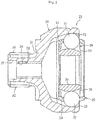
FIG. 1 is a sectional view for illustrating a fixed type constant velocity universal joint according to a first embodiment of the present invention. -
FIG. 2 is a sectional view for illustrating a method of assembling the fixed type constant velocity universal joint ofFIG. 1 and illustrating an assembled state of a sub-assembly. -
FIG. 3 is a sectional view for illustrating the method of assembling the fixed type constant velocity universal joint ofFIG. 1 and illustrating a state in which a shaft is fitted into an inner joint member. -
FIG. 4 is a sectional view for illustrating a state in which the fixed type constant velocity universal joint forms a maximum operating angle of 30° and the shaft is held in abutment against a stopper. -
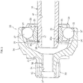
FIG. 5 is a sectional view for illustrating a state in which the fixed type constant velocity universal joint ofFIG. 1 is mounted to a wheel bearing. -
FIG. 6 is a sectional view for illustrating a fixed type constant velocity universal joint according to a second embodiment of the present invention. -
FIG. 7 is a sectional view for illustrating a fixed type constant velocity universal joint according to a third embodiment of the present invention. -
FIG. 8 is a sectional view for illustrating a related-art fixed type constant velocity universal joint. -
FIG. 9 is a sectional view for illustrating a state in which balls of the fixed type constant velocity universal joint ofFIG. 8 slip off. - Now, description is made of embodiments of the present invention with reference to
FIG. 1 to FIG. 7 . - A fixed type constant velocity universal joint according to the present invention is illustrated in
FIG. 1 . The fixed type constant velocity universal joint comprises an outerjoint member 23 having a radiallyinner surface 21 in which a plurality oftrack grooves 22 are formed in an axial direction, an innerjoint member 26 having a radiallyouter surface 24 in which a plurality oftrack grooves 25 are formed in the axial direction, a plurality oftorque transmitting balls 27 arranged in ball tracks formed of pairs of thetrack grooves 22 of the outerjoint member 23 and thetrack grooves 25 of the innerjoint member 26, and acage 28 interposed between the radiallyinner surface 21 of the outerjoint member 23 and the radiallyouter surface 24 of the innerjoint member 26 and configured to retain thetorque transmitting balls 27. - The outer
joint member 23 comprises acup section 30 having thetrack grooves 22 formed therein, and a shaft section (stem section) 32 formed continuously with abottom wall 31 of thecup section 30. A track groove bottom of each of thetrack grooves 22 is formed of only a circular-arc portion. Amale spline 33 is formed in thestem section 32 of the outerjoint member 23, and themale spline 33 is fitted to afemale spline 75 formed in a radially inner surface of ashaft section 70 of ahub wheel 66 as described later with reference toFIG. 5 . Further, ahole portion 34 is formed in a radially inner side of thestem section 32. Thehole portion 34 passes through thestem section 32, and comprises afemale thread portion 36 formed on a cup section side of thehole portion 34, and a large-diameter hole portion 37 formed on a side of thehole portion 34 opposite to the cup section side thereof. - A shaft-fitting
hole portion 29 is formed in the innerjoint member 26, and afemale spline 47 is formed in a radially inner surface of the shaft-fittinghole portion 29. Further, a track groove bottom of each of thetrack grooves 25 of the innerjoint member 26 is also formed of only a circular-arc portion. That is, the constant velocity universal joint illustrated inFIG. 1 is a so-called Rzeppa type constant velocity universal joint. The number of the torque transmitting balls may be set to any one of five to eight. - A
distal male spline 35a of ashaft 35 is fitted into the shaft-fittinghole portion 29 of the innerjoint member 26, and thedistal male spline 35a is fitted to thefemale spline 47 of the innerjoint member 26. Theshaft 35 has a radiallyinner hole portion 40 formed therein, and thus has a hollow shape. Further, acircumferential groove 38 is formed in an end portion of thedistal male spline 35a, and asnap ring 39 is mounted in thecircumferential groove 38. - A
stopper 41 configured to regulate a maximum operating angle is mounted in thehole portion 34 of thestem section 32 of the outerjoint member 23. Thestopper 41 comprises ahead portion 42 and ashaft portion 43. Further, theshaft portion 43 comprises abody portion 44 and adistal end portion 45. Amale thread portion 46 is formed in thebody portion 44. Thestopper 41 is fitted and fixed to thestem section 32 of the outerjoint member 23 by threadedly engaging themale thread portion 46 with thefemale thread portion 36 of thehole portion 34 of thestem section 32. Further, thedistal end portion 45 has a diameter smaller than a diameter of thebody portion 44, and extends into the radiallyinner hole portion 40 of theshaft 35. - Next, description is made of a method of assembling the constant velocity universal joint illustrated in
FIG. 1 . First, as illustrated inFIG. 2 , a sub-assembly is assembled by incorporating internal components, which comprise the innerjoint member 26, theballs 27, and thecage 28, into thecup section 30 of the outerjoint member 23. Next, as illustrated inFIG. 3 , thedistal male spline 35a of theshaft 35 is fitted into the shaft-fittinghole portion 29 so that thedistal male spline 35a and thefemale spline 47 of the innerjoint member 26 are fitted to each other. Under a state in which theshaft 35 is fitted into the innerjoint member 26, thesnap ring 39 is engaged with thecircumferential groove 38 of theshaft 35 so as to prevent theshaft 35 from slipping off. - After that, as illustrated in
FIG. 1 , thestopper 41 is inserted into thehole portion 34 of thestem section 32 of the outerjoint member 23. That is, themale thread portion 46 of thestopper 41 is threadedly engaged with thefemale thread portion 36 of thestem section 32. When the constant velocity universal joint having the above-mentioned configuration forms an operating angle, as illustrated inFIG. 4 , the radially inner surface of theshaft 35 is brought into abutment against thedistal end portion 45 of thestopper 41. - In this manner, the maximum operating angle is regulated.
- A state in which the constant velocity universal joint is mounted to a joint mounting device is illustrated in
FIG. 5 . In the first embodiment, the joint mounting device is a wheel bearing 58 that is mounted to a vehicle. Thewheel bearing 58 comprises anouter member 53 comprising a plurality of outer raceway surfaces 51 and 52 formed on an inner circumferential side of the wheel bearing 58, aninner member 56 comprising a plurality of inner raceway surfaces 54 and 55 formed on an outer circumferential side of the wheel bearing 58, and rollingelements 57 arranged between the outer raceway surfaces 51 and 52 of theouter member 53 and the inner raceway surfaces 54 and 55 of theinner member 56 that are opposed to the outer raceway surfaces 51 and 52 of theouter member 53. Thestem section 32 of the outerjoint member 23 of the constant velocity universal joint is fitted into theinner member 56 of thewheel bearing 58. - The
inner member 56 comprises thehub wheel 66 comprising awheel mounting flange 65, and comprises a pair ofinner rings hub wheel 66. That is, thehub wheel 66 comprises theshaft section 70 having a tubular shape, and theflange 65 formed on a radially outer surface of theshaft section 70. Further, a steppedportion 71 is formed on an inboard-side portion of the radially outer surface of theshaft section 70 with respect to theflange 65, and theinner rings portion 71. The inner raceway surfaces 54 and 55 are formed in radially outer surfaces of theinner rings bolt mounting hole 72 is formed in theflange 65, and ahub bolt 73 configured to fix a wheel and a brake rotor to theflange 65 is mounted in thebolt mounting hole 72. - The
female spline 75 is formed in the radially inner surface of theshaft section 70 of thehub wheel 66. When thestem section 32 of the outerjoint member 23 is fitted into theshaft section 70, themale spline 33 of thestem section 32 of the outerjoint member 23 is fitted to thefemale spline 75. Further, ascrew member 77 is inserted into theshaft section 70, and thescrew member 77 is threadedly engaged with thefemale thread portion 36 of thestem section 32 of the outerjoint member 23. In this manner, thestem section 32 of the outerjoint member 23 of the constant velocity universal joint is fitted and fixed into theinner member 56 of thewheel bearing 58. - After the constant velocity universal joint is mounted to the wheel bearing 58 as illustrated in
FIG. 5 , the constant velocity universal joint does not form a larger angle than necessary, in other words, the constant velocity universal joint does not form an angle causing falling of theballs 27. Thus, it is not necessary to regulate the maximum operating angle. Accordingly, the stopper 41 (seeFIG. 1 ) is removed, and thescrew member 77 is inserted instead so that the constant velocity universal joint is mounted to thewheel bearing 58. In this manner, thestopper 41 can be used only when the constant velocity universal joint may form a larger operating angle than necessary, that is, only until the constant velocity universal joint is mounted to the wheel bearing 58 after the balls are incorporated and then the shaft is mounted to the constant velocity universal joint. - According to the present invention, there is used the
stopper 41 that is inserted into thestem section 32 of the outerjoint member 23 and is brought into abutment against theshaft 35 until the constant velocity universal joint is mounted to the wheel bearing 58 after the balls are incorporated. Thus, thestopper 41 regulates the maximum operating angle so that the constant velocity universal joint cannot form a larger operating angle than necessary. Accordingly, falling of theballs 27 can be effectively prevented. In addition, it is only necessary to bring thestopper 41 into abutment against theshaft 35. Thus, it is not necessary to design theshaft 35, thecage 28, and the like into special components, and existing components can be used. As a result, increase in weight and cost can be prevented. In addition, thestopper 41 can be used only when the constant velocity universal joint may form a larger operating angle than necessary. Accordingly, thestopper 41 is removed under a state in which the constant velocity universal joint is mounted to the wheel bearing 58, thereby being capable of obtaining a lightweight constant velocity universal joint. - Accordingly, even when an axial length dimension of the
cup section 30 of the outerjoint member 23 is set to a small dimension so as to allow the constant velocity universal joint to form only the maximum operating angle of 30° or less, falling of theballs 27 can be effectively prevented. Thus, reduction in weight and cost can be achieved because the axial length dimension is set to the small dimension. Therefore, the constant velocity universal joint is optimum for use in a rear-wheel drive mechanism of an automobile that adopts thecup section 30 of the outerjoint member 23, which has a smaller axial length dimension. - According to the present invention, for example, the maximum operating angle can be set to 30° or less, and adjustment of the maximum operating angle can be set freely selectively. Accordingly, there can be provided the fixed type constant velocity universal joint capable of setting, in accordance with a device using the fixed type constant velocity universal joint, the operating angle to be equal to or smaller than an angle that is needed and causes no falling of the balls. In addition, the number of the
balls 27 can be set to any one of five to eight. Consequently, a large degree of design freedom is obtained, thereby achieving excellent designability. - Further, as illustrated in
FIG. 1 , themale thread portion 46 is formed in the radially outer surface of thestopper 41, and thefemale thread portion 36 to be threadedly engaged with thestopper 41 is formed in the radially inner surface of thestem section 32. Accordingly, thestopper 41 is fixed to the radially inner surface of thestem section 32. Thus, thestopper 41 can be prevented from, for example, slipping off, and stabilizes a function of preventing falling of theballs 27. Further, thedistal end portion 45 of thestopper 41 extends into the radially inner side of theshaft 35. Thus, it is not necessary to set a length dimension and a radial dimension of thestopper 41 with high accuracy. - In the first embodiment, there is described the Birfield type constant velocity universal joint in which the groove bottom of each of the
track grooves track grooves 22 of the outerjoint member 23 is formed of a circular-arc portion and a straight portion, and the groove bottom of each of thetrack grooves 25 of the innerjoint member 26 is formed of a straight portion and a circular-arc portion formed on a joint opening side. - In the first embodiment, the stopper is fixed by being threadedly engaged with the radially inner surface of the stem section. However, in a second embodiment of the present invention, as illustrated in
FIG. 6 , astopper 81 may be fixed by being press-fitted into the radially inner surface of thestem section 32. In the second embodiment, thestopper 81 comprises ahead portion 82 and ashaft portion 83. In the second embodiment, theshaft portion 83 is not threaded. Theshaft portion 83 comprises two protruding portions, that is, a first protrudingportion 84 and a second protrudingportion 85 protruding radially. In thehole portion 34 of thestem section 32, the first protrudingportion 84 is brought into abutment against ashoulder portion 86 formed between thefemale thread portion 36 and the large-diameter hole portion 37, and the second protrudingportion 85 is brought into press-contact with the radially inner surface of thefemale thread portion 36. In this manner, thestopper 81 is fitted and fixed to thestem section 32 of the outerjoint member 23. Further, theshaft portion 83 extends into the radiallyinner hole portion 40 of theshaft 35. - The other components of the fixed type constant velocity universal joint illustrated in
FIG. 6 are the same as those of the fixed type constant velocity universal joint illustrated inFIG. 1 . Accordingly, the same components as those of the constant velocity universal joint illustrated inFIG. 1 are denoted by the same reference symbols as those ofFIG. 1 , and description thereof is omitted. The fixed type constant velocity universal joint according to the second embodiment illustrated inFIG. 6 can obtain the same operations and effects as those of the fixed type constant velocity universal joint according to the first embodiment illustrated inFIG. 1 . - In the first embodiment, the stopper is fixed to the radially inner surface of the stem section. However, in a third embodiment of the present invention, as illustrated in
FIG. 7 , astopper 91 may be fixed to the radially inner surface of theshaft 87. In the third embodiment, thestopper 91 comprises ahead portion 92 and ashaft portion 93. Amale thread portion 94 is formed in theshaft portion 93. Further, theshaft 87 has a radiallyinner hole portion 88 formed therein, and thus has a hollow shape. The radiallyinner hole portion 88 comprises a large-diameter hole portion 95, atapered hole portion 96, and a small-diameter hole portion 97 in the stated order from the joint opening side. Afemale thread portion 98 is formed in the small-diameter hole portion 97. Thestopper 91 is fitted and fixed to theshaft 87 in such a manner that themale thread portion 94 formed in theshaft portion 93 of thestopper 91 is threadedly engaged with thefemale thread portion 98 formed in the small-diameter hole portion 97 of theshaft 87. - The other components of the fixed type constant velocity universal joint illustrated in
FIG. 7 are the same as those of the fixed type constant velocity universal joint illustrated inFIG. 1 . Accordingly, the same components as those of the constant velocity universal joint illustrated inFIG. 1 are denoted by the same reference symbols as those ofFIG. 1 , and description thereof is omitted. The fixed type constant velocity universal joint according to the third embodiment illustrated inFIG. 7 can obtain the same operations and effects as those of the fixed type constant velocity universal joint according to the first embodiment illustrated inFIG. 1 . In addition, in the fixed type constant velocity universal joint according to the third embodiment, thestopper 91 is fixed to theshaft 87. Thus, the operating angle can be reduced effectively. - The first to third embodiments of the present invention are described above. However, the present invention is not limited to the first to third embodiments, and various modifications can be made. For example, a material for the stopper is not particularly limited, and a resin such as reinforced plastic or a metal may be used. That is, it is only necessary that the stopper has strength capable of regulating the operating angle without being broken through abutment against (interference with) the shaft. A radial dimension and an axial dimension of the shaft portion of the stopper may be set freely selectively. The stopper can be collected and reused after the constant velocity universal joint is mounted to the joint mounting device. Thus, cost can be reduced.
- It is not necessary that the stopper is always mounted until the constant velocity universal joint is mounted to the joint mounting device after the balls are incorporated and then the shaft is mounted to the joint. The stopper may be temporarily mounted by the time the constant velocity universal joint is mounted to the joint mounting device. Further, the shaft may be solid, or may be partially hollow so as to comprise a recessed portion that is open to the stem section side. When the shaft is solid, the stopper is brought into abutment against any position of the shaft, and thus can regulate the maximum operating angle.
- The joint mounting device is not limited to a vehicle, and may comprise various industrial machines. Further, the outer joint member is not limited to use in a rear-wheel drive mechanism of an automobile. Further, the maximum operating angle to be regulated is not limited to 30° or less, and may be set to various angles.
-
- 21
- radially inner surface
- 22, 25
- track groove
- 23
- outer joint member
- 24
- radially outer surface
- 26
- inner joint member
- 27
- torque transmitting ball
- 28
- cage
- 30
- cup section
- 32
- stem section
- 35, 87
- shaft
- 36,
- 46 thread portion
- 41, 81, 91
- stopper
- 58
- wheel bearing
- 94, 98
- thread portion
Claims (8)
- A fixed type constant velocity universal joint, comprising:an outer joint member comprisinga cup section having a radially inner surface in which a plurality of track grooves are formed, anda hollow shaft section extending from a bottom portion of the cup section in an axial direction of the outer joint member;an inner joint member having a radially outer surface in which a plurality of track grooves are formed, and having a radially inner hole formed in the inner joint member so as to allow one end of a shaft to be coupled into the inner joint member;a plurality of torque transmitting balls arranged in ball tracks formed of pairs of the plurality of track grooves of the outer joint member and the plurality of track grooves of the inner joint member;a cage interposed between the radially inner surface of the outer joint member and the radially outer surface of the inner joint member and configured to retain the plurality of torque transmitting balls; anda stopper configured to regulate a maximum operating angle by being inserted into the hollow shaft section of the outer joint member and brought into abutment against the shaft until the fixed type constant velocity universal joint is mounted to a joint mounting device after the plurality of torque transmitting balls are incorporated and then the shaft is mounted to the fixed type constant velocity universal joint.
- The fixed type constant velocity universal joint according to claim 1, wherein the cup section of the outer joint member has an axial length that is set to a small length for use in a rear-wheel drive mechanism of an automobile.
- The fixed type constant velocity universal joint according to claim 1 or 2, wherein the maximum operating angle is set to 30° or less.
- The fixed type constant velocity universal joint according to any one of claims 1 to 3, further comprising:a thread portion formed in a radially outer surface of the stopper; andanother thread portion formed in a radially inner surface of the hollow shaft section so as to be threadedly engaged with the stopper.
- The fixed type constant velocity universal joint according to any one of claims 1 to 3, wherein the stopper is press-fitted into a radially inner surface of the hollow shaft section.
- The fixed type constant velocity universal joint according to any one of claims 1 to 5,
wherein at least a part of the shaft on the hollow shaft section side is hollow, and
wherein the stopper extends into a radially inner side of the shaft. - The fixed type constant velocity universal joint according to claim 6, further comprising:a thread portion formed in the stopper; andanother thread portion formed in a radially inner side of the shaft so as to be threadedly engaged with the stopper.
- A method of assembling a fixed type constant velocity universal joint comprising a stopper configured to regulate a maximum operating angle, the method comprising:incorporating, into a cup section of an outer joint member, internal components comprising an inner joint member, a cage, and torque transmitting balls;fitting a shaft into the inner joint member; andinserting the stopper into a shaft section of the outer joint member to bring a distal end portion of the stopper into abutment against the shaft until the fixed type constant velocity universal joint is mounted to a joint mounting device.
Applications Claiming Priority (2)
| Application Number | Priority Date | Filing Date | Title |
|---|---|---|---|
| JP2015050764A JP6532714B2 (en) | 2015-03-13 | 2015-03-13 | Fixed type constant velocity universal joint and assembling method of fixed type constant velocity universal joint |
| PCT/JP2016/055594 WO2016147829A1 (en) | 2015-03-13 | 2016-02-25 | Fixed constant velocity universal joint and method for assembling fixed constant velocity universal joint |
Publications (2)
| Publication Number | Publication Date |
|---|---|
| EP3269991A1 true EP3269991A1 (en) | 2018-01-17 |
| EP3269991A4 EP3269991A4 (en) | 2018-12-05 |
Family
ID=56918940
Family Applications (1)
| Application Number | Title | Priority Date | Filing Date |
|---|---|---|---|
| EP16764659.5A Withdrawn EP3269991A4 (en) | 2015-03-13 | 2016-02-25 | Fixed constant velocity universal joint and method for assembling fixed constant velocity universal joint |
Country Status (5)
| Country | Link |
|---|---|
| US (1) | US20180106296A1 (en) |
| EP (1) | EP3269991A4 (en) |
| JP (1) | JP6532714B2 (en) |
| CN (1) | CN107407339A (en) |
| WO (1) | WO2016147829A1 (en) |
Cited By (1)
| Publication number | Priority date | Publication date | Assignee | Title |
|---|---|---|---|---|
| US10875357B2 (en) | 2015-10-27 | 2020-12-29 | Ntn Corporation | Fixed constant velocity universal joint, and bearing device for wheels |
Families Citing this family (1)
| Publication number | Priority date | Publication date | Assignee | Title |
|---|---|---|---|---|
| JP7412099B2 (en) * | 2019-07-05 | 2024-01-12 | Ntn株式会社 | Power transmission mechanism and vehicle |
Family Cites Families (6)
| Publication number | Priority date | Publication date | Assignee | Title |
|---|---|---|---|---|
| DE2461289B1 (en) * | 1974-12-23 | 1975-11-13 | Loehr & Bromkamp Gmbh | Constant velocity swivel |
| DE2807921A1 (en) * | 1978-02-24 | 1979-08-30 | Loehr & Bromkamp Gmbh | CONTINUOUS SWIVEL JOINT |
| JPS5927543Y2 (en) * | 1978-03-16 | 1984-08-09 | エヌ・テ−・エヌ東洋ベアリング株式会社 | Constant velocity joint |
| JP5167903B2 (en) * | 2008-03-28 | 2013-03-21 | 株式会社ジェイテクト | Wheel bearing device |
| JP2011153642A (en) * | 2010-01-26 | 2011-08-11 | Ntn Corp | Fixed constant velocity universal joint and method for assembling the same |
| CN102927146B (en) * | 2012-10-25 | 2015-04-22 | 长城汽车股份有限公司 | Constant velocity universal joint with fixed centre and automobile applying same |
-
2015
- 2015-03-13 JP JP2015050764A patent/JP6532714B2/en not_active Expired - Fee Related
-
2016
- 2016-02-25 WO PCT/JP2016/055594 patent/WO2016147829A1/en not_active Ceased
- 2016-02-25 US US15/556,443 patent/US20180106296A1/en not_active Abandoned
- 2016-02-25 CN CN201680014132.7A patent/CN107407339A/en active Pending
- 2016-02-25 EP EP16764659.5A patent/EP3269991A4/en not_active Withdrawn
Cited By (1)
| Publication number | Priority date | Publication date | Assignee | Title |
|---|---|---|---|---|
| US10875357B2 (en) | 2015-10-27 | 2020-12-29 | Ntn Corporation | Fixed constant velocity universal joint, and bearing device for wheels |
Also Published As
| Publication number | Publication date |
|---|---|
| US20180106296A1 (en) | 2018-04-19 |
| JP2016169825A (en) | 2016-09-23 |
| CN107407339A (en) | 2017-11-28 |
| WO2016147829A1 (en) | 2016-09-22 |
| EP3269991A4 (en) | 2018-12-05 |
| JP6532714B2 (en) | 2019-06-19 |
Similar Documents
| Publication | Publication Date | Title |
|---|---|---|
| EP2806180B1 (en) | Constant velocity joint | |
| US8944694B2 (en) | Bearing device for driving wheel, and its assembling method | |
| WO2014136626A1 (en) | Propeller shaft and adapter member for propeller shaft | |
| EP2920479B1 (en) | Inner race of a constant velocity joint and boot sleeve | |
| EP2634012B1 (en) | Wheel support device | |
| EP2708376A1 (en) | Vehicle bearing apparatus | |
| US10352365B2 (en) | Power transmission shaft and spline-processing method | |
| US10962063B2 (en) | Fixed constant velocity universal joint | |
| EP3369956B1 (en) | Fixed constant velocity universal joint, and bearing device for wheels | |
| EP2634011A1 (en) | Spline forming method for hub unit, hub unit, spline forming method for joint, and joint | |
| US20180106296A1 (en) | Fixed constant velocity universal joint and method for assembling fixed constant velocity universal joint | |
| US9097287B2 (en) | Inner race and boot sleeve | |
| JP2014233782A (en) | Manufacturing method for machine element and chuck device | |
| JP6486694B2 (en) | Constant velocity universal joint | |
| EP2634013B1 (en) | Wheel support device | |
| JP2020067150A (en) | Connection structure between power transmission shaft and hub ring | |
| JP6901241B2 (en) | Constant velocity universal joint | |
| JP2011153642A (en) | Fixed constant velocity universal joint and method for assembling the same | |
| KR20180059142A (en) | Structure for preventing stick-slip noise applied constant velocity joint and manufacturing method thereof |
Legal Events
| Date | Code | Title | Description |
|---|---|---|---|
| PUAI | Public reference made under article 153(3) epc to a published international application that has entered the european phase |
Free format text: ORIGINAL CODE: 0009012 |
|
| 17P | Request for examination filed |
Effective date: 20171011 |
|
| AK | Designated contracting states |
Kind code of ref document: A1 Designated state(s): AL AT BE BG CH CY CZ DE DK EE ES FI FR GB GR HR HU IE IS IT LI LT LU LV MC MK MT NL NO PL PT RO RS SE SI SK SM TR |
|
| AX | Request for extension of the european patent |
Extension state: BA ME |
|
| DAV | Request for validation of the european patent (deleted) | ||
| DAX | Request for extension of the european patent (deleted) | ||
| A4 | Supplementary search report drawn up and despatched |
Effective date: 20181029 |
|
| RIC1 | Information provided on ipc code assigned before grant |
Ipc: F16D 3/20 20060101ALI20181023BHEP Ipc: F16D 3/223 20110101AFI20181023BHEP |
|
| STAA | Information on the status of an ep patent application or granted ep patent |
Free format text: STATUS: THE APPLICATION HAS BEEN WITHDRAWN |
|
| 18W | Application withdrawn |
Effective date: 20191007 |