EP3269987A1 - Connection fastener - Google Patents
Connection fastener Download PDFInfo
- Publication number
- EP3269987A1 EP3269987A1 EP17181391.8A EP17181391A EP3269987A1 EP 3269987 A1 EP3269987 A1 EP 3269987A1 EP 17181391 A EP17181391 A EP 17181391A EP 3269987 A1 EP3269987 A1 EP 3269987A1
- Authority
- EP
- European Patent Office
- Prior art keywords
- fastener
- connection
- holding
- attaching
- portions
- Prior art date
- Legal status (The legal status is an assumption and is not a legal conclusion. Google has not performed a legal analysis and makes no representation as to the accuracy of the status listed.)
- Granted
Links
Images




Classifications
-
- F—MECHANICAL ENGINEERING; LIGHTING; HEATING; WEAPONS; BLASTING
- F16—ENGINEERING ELEMENTS AND UNITS; GENERAL MEASURES FOR PRODUCING AND MAINTAINING EFFECTIVE FUNCTIONING OF MACHINES OR INSTALLATIONS; THERMAL INSULATION IN GENERAL
- F16B—DEVICES FOR FASTENING OR SECURING CONSTRUCTIONAL ELEMENTS OR MACHINE PARTS TOGETHER, e.g. NAILS, BOLTS, CIRCLIPS, CLAMPS, CLIPS OR WEDGES; JOINTS OR JOINTING
- F16B15/00—Nails; Staples
- F16B15/08—Nails; Staples formed in integral series but easily separable
-
- B—PERFORMING OPERATIONS; TRANSPORTING
- B25—HAND TOOLS; PORTABLE POWER-DRIVEN TOOLS; MANIPULATORS
- B25C—HAND-HELD NAILING OR STAPLING TOOLS; MANUALLY OPERATED PORTABLE STAPLING TOOLS
- B25C1/00—Hand-held nailing tools; Nail feeding devices
- B25C1/001—Nail feeding devices
- B25C1/003—Nail feeding devices for belts of nails
-
- F—MECHANICAL ENGINEERING; LIGHTING; HEATING; WEAPONS; BLASTING
- F16—ENGINEERING ELEMENTS AND UNITS; GENERAL MEASURES FOR PRODUCING AND MAINTAINING EFFECTIVE FUNCTIONING OF MACHINES OR INSTALLATIONS; THERMAL INSULATION IN GENERAL
- F16B—DEVICES FOR FASTENING OR SECURING CONSTRUCTIONAL ELEMENTS OR MACHINE PARTS TOGETHER, e.g. NAILS, BOLTS, CIRCLIPS, CLAMPS, CLIPS OR WEDGES; JOINTS OR JOINTING
- F16B27/00—Bolts, screws, or nuts formed in integral series but easily separable, particularly for use in automatic machines
Definitions
- the present invention relates to a connection fastener used for a driving tool.
- connection fastener for connecting a plurality of fasteners with a connection band can set a great deal of fasteners to a driving tool en bloc and continuously inject the great deal of fasteners
- the connection fastener is used in various driving tools.
- the connection band of this connection fastener holds the fastener in two upper and lower places as described in, for instance, JP-U-A-H03-96417 , and thereby can stably hold the fastener.
- connection fastener used for this driving tool uses a connection band according to specifications of the tool, and thereby enables use for the same tool even when the connection fasteners have different lengths.
- a shape or the like of the connection band is designated by the specifications of the tool, and cannot be freely changed.
- a vertical width (a distance between a lower holding portion and an upper holding portion) of the connection band is designated by a width capable of corresponding to a feed motion of the connection fastener of the tool and a discharge motion of the connection band, and cannot be freely changed.
- connection band cannot stably hold the fastener, this causes an obstacle that the fastener driven in an oblique state is buckled or that the connection band removed and spread from the fastener is pulled into a machine so that the feed motion of the connection fastener is not smoothly performed.
- the fastener that cannot be held by the connection band regulated by the tool in the related art cannot be used, and restrictions are placed on a length of the fastener that can be used by a tool.
- An object of the present invention is to provide a connection fastener capable of stably supporting short fasteners even when a width of a connection band (a connection portion) is regulated by a tool, and thereby using the short fasteners without changing specifications of the tool.
- the present invention was made to solve the above problem, and is characterized by the following.
- connection fastener includes: a plurality of fasteners each of which includes a head portion provided at one end portion side and a tapered leading end portion provided at the other end portion side; a sheet-shaped connection portion that is configured to connect the plurality of fasteners in a parallel direction; and attaching portions that are separate from the connection portion attached to the fasteners such that each attaching portion covers at least one part of each leading end portion.
- the connection portion includes: first holding portions each of which is configured to support ahead portion side of each fastener; and second holding portions each of which is configured to support at least one part of a circumferential surface of each attaching portion.
- the fasteners are stretched by the attaching portions and can be held by the second holding portions, even when a width of the connection portion is regulated by a tool, the fasteners can be stably supported regardless of lengths of the fasteners.
- the attaching portions are members which are separate from and are independent of the connection portion, the attaching portions are not pulled and inclined by the connection portion when removed from the connection portion. Therefore, the fasteners can be prevented from being inclined and buckled. No energy is lost to cut the connection portion.
- the attaching portion that is more easily stabilized in dimensional precision than the fastener formed of a metal is used. Thereby, dimensions of the attaching portions and dimensions of the second holding portions can be made compatible with each other, and a holding force of the fastener held via the attaching portion by the second holding portion can be enhanced.
- the attaching portion is attached to the fastener, and thereby a diameter of the toe side (the leading end portion side) of the fastener is increased. For this reason, the fastener is prevented from falling within an injection path during driving. Therefore, it is possible to stabilize a driving posture of the fastener to prevent buckling.
- the diameter of the second holding hole holding the attaching portion provided at the second holding portion is larger than that of the first holding hole holding the head portion side of the fastener provided at the first holding portion. According to this configuration, the shank of the fastener is held by the first holding hole having a relatively small diameter, and the attaching portion is held by the second holding hole having a relatively large diameter. Thus, the fastener can be tightly held even at the second portion thickened by the amount of attaching the attaching portion.
- the opening width of the opening slit (opening edge) of the second holding hole that supports and holds the attaching portion provided at the second holding portion is larger than that of the opening slit (opening edge) of the first holding hole that supports and holds the head portion side of the fastener provided at the first holding portion.
- the fastener can be loaded and held even at the lower portion thickened by the amount of attaching the attaching portion without difficulty, and assemblability is good. Even when the fastener is driven, the opening width of the opening slit (opening edge) of the second holding hole is large, and thus the fastener can be smoothly removed from the connection portion.
- the fastener includes the shank provided between the head portion and the leading end portion, and the second holding portion supports and holds the attaching portion at the position at which the second holding portion overlaps the tapered leading end portion of the fastener or at the position at which the second holding portion does not overlap the fastener.
- this short fastener is stretched by the attaching portion, and is held by the second holding portion.
- the short fastener limited by specifications of the tool so far can be used. Since even the short fastener is stably held, and since the driving posture of the fastener is stable, the buckling during driving can be prevented.
- the length of the shank when viewed in the axial direction of the fastener, is shorter than that of the band-shaped portion. According to this configuration, even in the short fastener in which the length of the shank is shorter than that of the band-shaped portion, this short fastener is stretched by the attaching portion, and is held by the second holding portion. Thus, upper and lower portions of the shank of the fastener can be reliably held.
- the fastener includes the stepped portion at the shank.
- the stepped portion is formed such that the outer diameter of the leading end portion side is smaller than that of the head side, and faces the upper edge portion of the attaching portion.
- the attaching portion includes the flange portion protruding below the second holding portion in the outer circumferential direction. According to this configuration, since the second holding portion is prevented from falling off by the flange portion, the second holding portion is prevented from being removed from the attaching portion.
- the flange portion is provided, and thereby the diameter of the toe side of the fastener is increased.
- an effect of preventing the fastener from falling within the injection path during driving can be enhanced. Therefore, it is possible to stabilize the driving posture of the fastener to prevent the buckling.
- the attaching portion includes the fall-preventing shape for preventing the second holding portion from falling off. According to this configuration, since the second holding portion is prevented from falling off by the fall-preventing shape, the second holding portion is prevented from being removed from the attaching portion.
- the fall-preventing shape is provided for the fastener, there is a problem that penetration resistance of the fastener is increased or that the fastener is easily buckled.
- the fall-preventing shape is provided for the attaching portion, and thereby such a problem does not occur.
- connection fastener 10 according to the present embodiment will be described with reference to the drawings.
- connection fastener 10 is configured to connect a plurality of fasteners 11 with a connection band (a connection portion) 20, so that a great deal of fasteners 11 can be set for a driving tool en bloc and be continuously injected.
- the driving tool is provided with a magazine for containing the connection fastener 10, and a feed mechanism for feeding the connection fastener 10 stored in the magazine to a leading end portion of a tool main body thereof.
- the feed mechanism is linked to a driving motion and feeds the connection fastener 10 one by one, thereby setting the fastener 11 in the forefront of the connection fastener 10 for an injection path 40 provided at the leading end portion of the tool main body.
- the fastener 11 set for the injection path 40 in this way is driven out by a driver 41 operated by a striking mechanism of the driving tool.
- the fastener 11 driven out by the driver 41 passes through the injection path 40 and is injected from an injection port provided at the leading end portion of the tool main body.
- connection fastener 10 arranges and connects the fasteners 11 in parallel (in a parallel direction) such that a line connecting the centers of the fasteners 11 becomes a straight line. Thereby, the connection fastener 10 is formed in a straight band shape.
- the fastener 11 is a concrete pin that is driven into, for instance, concrete or a siding member, and is, as illustrated in Fig. 2A , provided with a head portion 12, an under-head tapered portion 13 that is continuous to the head portion 12, a shank 14 that is continuous to the under-head tapered portion 13, and a tapered leading end portion 15 that is continuous to the shank 14.
- the head portion 12 is a discoid region being subject to the driving of the driver 41.
- the under-head tapered portion 13 is for smoothly connecting the head portion 12 and the shank 14, and is a region whose diameter is gradually reduced in a direction from the head portion 12 to the shank 14.
- the shank 14 is a region that is formed in a columnar shape and generates pullout resistance when driven into a driven material.
- the leading end portion 15 is a region that is formed in a pointed shape and is pierced into a driven material. In the present embodiment, the leading end portion 15 is formed in a shell shape.
- the fastener 11 may have a shape with a head portion, a shank of a gently tapered shape that is continuous to the head portion (wherein an under-head tapered portion that is continuous to the head portion may be present between the head portion and the shank), and a tapered leading end portion that is continuous to the shank.
- a stepped portion 14a for reducing penetration resistance is continuously formed at the shank 14 of the fastener 11 according to the present embodiment.
- a diameter of the shank 14 is configured such that, in comparison with a diameter of a straight portion closer to the head portion 12 than the stepped portion 14a, a diameter of a straight portion closer to the leading end portion 15 than the stepped portion 14a is smaller.
- a cylindrical member 30 acting as a tubular member (an attaching portion) is attached to the shank 14 of the fastener 11.
- the cylindrical member 30 is a member formed of aluminum or a synthetic resin and, as illustrated in Figs. 4A and 4B , includes a tubular portion 31 and a flange portion 33 formed to protrude from an opening edge of the tubular portion 31.
- the flange portion 33 may protrude below a lower holding portion 23 in an outer circumferential direction or be provided at a position other than the opening edge.
- the flange portion 33 may be formed on an outer circumferential surface of the tubular portion 31 to protrude in a radial direction.
- the flange portion 33 may be formed separately from and independently of the tubular portion 31.
- a shape of the flange portion 33 is not limited to a circular shape as shown in Fig. 4A , but it may be a shape in which an outer circumference is on a cylindrical locus.
- the shape of the flange portion 33 may be a polygonal shape or a rectangular shape having a cutout portion.
- a shape of the cylindrical member 30 is not also limited to a circular shape, but it may be a tubular shape in which an inner circumference is on a cylindrical locus.
- the cylindrical member 30 may be a tubular member having a polygonal shape or a rectangular shape which forms a cutout portion such that the tubular member covers at least one part of the shank 14.
- An inner diameter of the tubular portion 31 is formed in such a size as to be able to forcibly insert the shank 14 of the fastener 11 (which is closer to the leading end portion 15 than the stepped portion 14a).
- the leading end portion 15 of the fastener 11 is inserted into the tubular portion 31, and thereby the cylindrical member 30 can be attached to the fastener 11.
- the fastener 11 can be inserted up to a position where the stepped portion 14a reaches an upper edge portion 32 of the cylindrical member 30, and an inserted position of the cylindrical member 30 into the fastener 11 is configured to be determined by the stepped portion 14a, so that assemblability is good.
- connection band 20 connecting the fasteners 11 is a sheet-shaped member as shown in Figs. 3A and 3B , and is formed of a synthetic resin in the present embodiment. Although it is shown in the figure that the connection band 20 is short in length, the connection band 20 is actually formed from one long sheet in which the same shape is continuous in a vertical direction of Fig. 3A .
- This connection band 20 is provided with upper holding portions (first holding portions) 22, each of which holds the head portion 12 side of the fastener 11, lower holding portions (second holding portions) 23, each of which supports and holds the cylindrical member 30 attached to the fastener 11, and a band-shaped portion 21 that connects the upper holding portions 22 and the lower holding portions 23.
- the upper holding portions 22 and the lower holding portions 23 are provided by the same number to be correspond to each other, and one fastener 11 is configured to be held by a pair of corresponding upper and lower holding portions 22 and 23.
- the band-shaped portion 21 runs in a longitudinal direction to connect all of the upper and lower holding portions 22 and 23.
- connection band 20 the upper holding portions 22, the lower holding portions 23, and the band-shaped portion 21 are formed on the same plane, and a folding groove 20a is formed between the upper holding portions 22 and the band-shaped portion 21 and between the lower holding portions 23 and the band-shaped portion 21.
- the connection band 20 is folded along the folding groove 20a. Thereby, as illustrated in Fig. 2A , the connection band 20 formed from one long sheet is deformed in a C shape to support and hold the fasteners 11.
- the upper holding portion 22 supports and holds the top of the shank 14 of the fastener 11.
- the upper holding portion 22 is provided with an upper slit 22a whose width is narrower than a maximum diameter of the shank 14 of the fastener 11, and an upper holding hole (a first holding hole) 22b that is provided behind the upper slit 22a.
- a diameter of the upper holding hole 22b is greater than the maximum diameter of the shank 14 of the fastener 11.
- the upper slit 22a is provided as an opening edge of the upper holding hole 22b, and communicates with the upper holding hole 22b.
- the lower holding portion 23 supports and holds the tubular portion 31 of the cylindrical member 30. Additionally, the lower holding portion 23 may be configured to support and hold at least one part of a circumferential surface of the cylindrical member 30. As illustrated in Fig. 3A , the lower holding portion 23 is provided with a lower slit 23a whose width is narrower than a diameter of the tubular portion 31 of the cylindrical member 30, and a lower holding hole (a second holding hole) 23b that is provided behind the lower slit 23a. A diameter of the lower holding hole 23b is greater than the diameter of the tubular portion 31 of the cylindrical member 30. The lower slit 23a is provided as an opening edge of the lower holding hole 23b, and communicates with the lower holding hole 23b.
- the width DW1 of the lower slit 23a (an opening width of the opening slit (opening edge) of the lower holding hole 23b) is formed to be greater than the width UW1 of the upper slit 22a (an opening width of the opening slit (opening edge) of the upper holding hole 22b), and a diameter DW2 of the lower holding hole 23b is formed to be greater than a diameter UW2 of the upper holding hole 22b.
- an inner diameter of the lower holding hole 23b is increased depending on a lower portion of the fastener 11 which is thickened by the amount of attaching the cylindrical member 30, and the fastener 11 can be stably held.
- the shank 14 of the fastener 11 is loaded from the upper slit 22a to the upper holding hole 22b, and the cylindrical member 30 is loaded from the lower slit 23a to the lower holding hole 23b.
- the width DW1 of the lower slit 23a is increased depending on the lower portion of the fastener 11 which is thickened by the amount of attaching the cylindrical member 30, the fastener 11 can be loaded and held without difficulty, and the assemblability is good.
- feeding holes 21a are formed in the band-shaped portion 21 of the connection band 20 at the same intervals as those at which the fasteners 11 are held.
- the feeding holes 21a are intended for use of the feed mechanism of the driving tool. That is, the feed mechanism is operated with feed claws thereof engaged with the feeding holes 21a, and thereby the fasteners 11 are configured to be fed to the injection path 40 in turn.
- a width of the band-shaped portion 21 having these feeding holes 21a (a length H1 of the band-shaped portion 21 when viewed in an axial direction of the fastener 11) (see Fig. 2A ) is regulated by the driving tool, and cannot be easily changed.
- the feed mechanism cannot normally perform the feed operation. Therefore, the length H1 of the band-shaped portion 21 cannot be changed.
- a structure of the related art has a problem that, since the length H1 of the band-shaped portion 21 cannot be reduced, short fasteners 11 cannot be held by the connection band 20.
- a length H2 of the shank 14 of the fastener 11 is configured to be shorter than the length H1 of the band-shaped portion 21 of the connection band 20.
- the lower holding portion 23 is located at a position at which it overlaps the leading end portion 15 of the fastener 11.
- this short fastener 11 is to be held in the structure of the related art, there is a possibility of the lower holding portion 23 falling out of the leading end portion 15 of the fastener 11 as illustrated in Fig. 2B , and the fastener 11 cannot be reliably held.
- the cylindrical member 30 is attached to the fastener 11, and since the lower holding portion 23 supports and holds the cylindrical member 30, the upper and lower portions of the fastener 11 can be reliably held. Therefore, the short fastener 11 limited by specifications of the tool so far can be used, and buckling during driving can be prevented because the driving posture of the fastener 11 is stable.
- the fastener 11 when the fastener 11 is driven by the driver 41 within the injection path 40 of the driving tool, the fastener 11 moves within the injection path 40 with the cylindrical member 30 attached to a toe of the fastener 11. For this reason, a tilt of the fastener 11 is suppressed.
- the fastener 11 is inclined within the injection path 40 and is obliquely driven as illustrated in Fig. 5B , which is attributed to the buckling or the like of the fastener 11.
- the connection fastener 10 according to the present embodiment is configured to be able to prevent the buckling during driving.
- the cylindrical member 30 is provided separately from and independently of the connection band 20, there is no need to sever the cylindrical member 30 from the connection band 20 during driving of the fastener 11. For this reason, when the fastener 11 is driven by the driver 41 within the injection path 40 of the driving tool, the cylindrical member 30 is removed from the connection band 20 as illustrated in Figs. 6A to 6D , but the cylindrical member 30 is not pulled and inclined by the connection band 20. Therefore, the fastener 11 can be prevented from being inclined and buckled. Energy is not lost in order to cut the connection band 20.
- connection band 20 When the cylindrical member 30 is provided as a part of the connection band 20, the cylindrical member 30 is pulled by the connection band 20 when severed from the connection band 20 as illustrated in Figs. 7A to 7C , so that the cylindrical member 30 is inclined. For this reason, there is a possibility of the fastener 11 being inclined and buckled. The loss of energy to cut the connection band 20 is caused. In this regard, when the connection band 20 and the cylindrical member 30 are separately provided as in the present embodiment, this problem does not occur.
- the lower holding portion 23 supports and holds the cylindrical member 30 at a position at which it overlaps the leading end portion 15 of the fastener 11 when viewed from a side direction of the fastener 11 has been described.
- the lower holding portion 23 supports and holds the cylindrical member 30 at a position at which the tapered leading end portion 15 of the fasteners 11 reaches the lower holding portion 23 in the axial direction of the fasteners 11.
- the embodiment is not limited thereto.
- the lower holding portion 23 may be configured to support and hold the cylindrical member 30 at a position at which it does not overlap the fastener 11 when viewed from a side direction of the fastener 11.
- the lower holding portion 23 supports and holds the cylindrical member 30 at a position at which the tapered leading end portion 15 of the fasteners 11 does not reach the lower holding portion 23 in the axial direction of the fasteners 11. Even when the very short fastener 11 is used in this way, the fastener 11 is lengthened by the cylindrical member 30, and thereby the fastener 11 can be stably held.
- the flange portion 33 of the cylindrical member 30 may be disposed to make it possible to come into contact with a lower portion of the lower holding portion 23. Thereby, since spreading of the lower holding portion 23 can be suppressed by the flange portion 33, the lower holding portion 23 can be prevented from being removed from the cylindrical member 30.
- the concrete pin has been described as the fastener 11 by way of example, but the embodiment is not limited thereto.
- a nail may be used as the fastener 11.
- a screw may be used as the fastener 11.
- the flange portion 33 is provided for the cylindrical member 30, but the embodiment is not limited thereto. As illustrated in Fig. 10A , the flange portion 33 may not be provided for the cylindrical member 30. In addition, as illustrated in Figs. 10B and 10C , a long fastener 11 may be used.
- a fall-preventing shape for preventing the lower holding portion 23 from falling off may be provided for the cylindrical member 30.
- the tubular portion 31 of the cylindrical member 30 has a tapered shape 34 whose diameter is gradually increased in a direction of a leading end portion thereof, and the tapered shape 34 is held by the lower holding portion 23.
- a fall-preventing shape for preventing the lower holding portion 23 from falling off may be formed.
- an inserted position of the lower holding portion 23 of the connection band 20 can depend on the tapered shape 34, and thus the assemblability can be improved.
- the cylindrical member 30 of the tapered shape 34 falls off from the lower holding portion 23 as it is, and thus the fastener 11 can be smoothly removed from the connection band 20.
- a stepped shape 35 having a large diameter is formed at a leading end portion side of the tubular portion 31 of the cylindrical member 30, and the lower holding portion 23 is engaged with this stepped shape 35.
- the tubular portion 31 of the cylindrical member 30 may be formed in the fall-preventing shape for preventing the lower holding portion 23 from falling off.
- the inserted position of the lower holding portion 23 of the connection band 20 can depend on the stepped shape 35, and thus the assemblability can be improved.
- a concave shape 36 is formed at the tubular portion 31 of the cylindrical member 30 in a circumferential groove shape, and the lower holding portion 23 is engaged with this concave shape 36.
- the tubular portion 31 of the cylindrical member 30 may be formed in the fall-preventing shape for preventing the lower holding portion 23 from falling off.
- the inserted position of the lower holding portion 23 of the connection band 20 can depend on the concave shape 36, and thus the assemblability can be improved.
- a bulgy shape 37 swollen in an outer circumferential direction is provided at the leading end portion side of the tubular portion 31 of the cylindrical member 30, and the lower holding portion 23 is engaged with this bulgy shape 37.
- the tubular portion 31 of the cylindrical member 30 may be formed in the fall-preventing shape for preventing the lower holding portion 23 from falling off.
- the inserted position of the lower holding portion 23 of the connection band 20 can depend on the bulgy shape 37, and thus the assemblability can be improved.
- a large diameter shape 38 is formed by making a large diameter for the leading end portion side of the tubular portion 31 of the cylindrical member 30, and the large diameter shape 38 is held by the lower holding portion 23.
- the tubular portion 31 of the cylindrical member 30 may be formed in the fall-preventing shape for preventing the lower holding portion 23 from falling off.
- the inserted position of the lower holding portion 23 of the connection band 20 can depend on the large diameter shape 38, and thus the assemblability can be improved.
- a stepped portion 39 may be provided at the tubular portion 31 of the cylindrical member 30.
- a leading end portion side of the stepped portion 39 is formed to be larger in diameter than a trailing end portion side of the stepped portion 39.
- This stepped portion 39 is disposed closer to the toe side (the leading end portion 15 side) of the fastener 11 than the lower holding portion 23, and is configured not to be contact with the lower holding portion 23. Even in this configuration, as in the form shown in Fig. 11B , the lower holding portion 23 can be inhibited from being spread by the stepped portion 39, and the tubular portion 31 of the cylindrical member 30 can be formed in the fall-preventing shape for preventing the lower holding portion 23 from falling off.
- the stepped portion 39 is formed by corners whose cross sections are formed at a right angle. In this way, the corners of the stepped portion 39 are formed at a right angle, and thereby the lower holding portion 23 is easily caught, and thus an effect of preventing the spread of the lower holding portion 23 can be enhanced.
- the corners of the stepped portion 39 are not limited to the right angle, and may have an R shape as small as possible.
- connection band 20 including the cylindrical member 30 attached to the fastener 11 is provided with the upper holding portions 22, each of which supports and holds the head portion 12 side of the fastener 11, and the lower holding portions 23, each of which supports and holds the cylindrical member 30 attached to the fastener 11. According to this configuration, since the fasteners 11 are stretched by the cylindrical members 30 and are held by the lower holding portions 23, even when the width of the connection band 20 is regulated by the tool, the fasteners 11 can be stably supported regardless of the lengths of the fasteners 11.
- the cylindrical members 30 are members which are separate from and are independent of the connection band 20 because the cylindrical members 30 are not pulled and inclined by the connection band 20 when removed from the connection band 20. Therefore, the fasteners 11 can be prevented from being inclined and buckled. No energy is lost to cut the connection band 20.
- the cylindrical member 30 that is more easily stabilized in dimensional precision than the fastener 11 formed of a metal is used. Thereby, dimensions of the cylindrical member 30 and dimensions of the lower holding portion 23 can be made compatible with each other, and a holding force of the fastener 11 held via the cylindrical member 30 by the lower holding portion 23 can be enhanced.
- the cylindrical member 30 is attached to the fastener 11, and thereby the diameter of the toe side (the leading end portion 15 side) of the fastener 11 is increased. For this reason, the fastener 11 is prevented from falling within the injection path 40 during driving. Therefore, it is possible to stabilize the driving posture of the fastener 11 to prevent the buckling.
- the diameter of the lower holding hole 23b holding the cylindrical member 30 provided at the lower holding portion 23 is larger than that of the upper holding hole 22b holding the head portion 12 side of the fastener 11 provided at the upper holding portion 22. According to this configuration, the shank 14 of the fastener 11 is held by the upper holding hole 22b having a relatively small diameter, and the cylindrical member 30 is held by the lower holding hole 23b having a relatively large diameter. Thus, the fastener 11 can be tightly held even at the lower portion thickened by the amount of attaching the cylindrical member 30.
- the lower holding portion 23 supports and holds the cylindrical member 30 at a position at which it overlaps the tapered leading end portion 15 of the fastener 11 or at a position at which it does not overlap the fastener 11. According to this configuration, even in the short fastener 11 located at the position at which the lower holding portion 23 overlaps the leading end portion 15 of the fastener 11 or at the position at which the lower holding portion 23 does not overlap the fastener 11, this short fastener 11 is stretched by the cylindrical member 30, and is held by the lower holding portion 23. Thus, the fastener 11 can be stably held.
- the length H2 of the shank 14 is shorter than the length H1 of the band-shaped portion 21. According to this configuration, even in the short fastener 11 in which the length H2 of the shank 14 is shorter than the length H1 of the band-shaped portion 21, this short fastener 11 is stretched by the cylindrical member 30, and is held by the lower holding portion 23. Thus, the fastener 11 can be stably held.
- the cylindrical member 30 includes the flange portion 33 that faces the lower portion of the lower holding portion 23 and is formed to protrude in a radial direction of the outer circumference of the cylindrical member 30. According to this configuration, since the lower holding portion 23 is prevented from falling off by the flange portion 33, the lower holding portion 23 is prevented from being removed from the cylindrical member 30.
- the flange portion 33 is provided, and thereby the diameter of the toe side of the fastener 11 is increased.
- an effect of preventing the fastener 11 from falling within the injection path 40 during driving can be enhanced. Therefore, it is possible to stabilize the driving posture of the fastener 11 to prevent the buckling.
- the fastener 11 includes the stepped portion 14a at the shank 14, and the stepped portion 14a is formed such that the outer diameter thereof close to the leading end portion 15 is smaller than that close to the head portion 12, and faces the upper edge portion 32 of the cylindrical member 30. According to this configuration, when the cylindrical member 30 is attached to the fastener 11, the position of the cylindrical member 30 depends on the stepped portion 14a, and thus a problem that the attached position of the cylindrical member 30 to the fastener 11 is made too shallow or too deep can be avoided.
- the cylindrical member 30 includes the fall-preventing shape for preventing the lower holding portion 23 from falling off. According to this configuration, since the lower holding portion 23 is prevented from falling off by the fall-preventing shape, the lower holding portion 23 is prevented from being removed from the cylindrical member 30.
- the fall-preventing shape is provided for the fastener 11
- the fall-preventing shape is provided for the cylindrical member 30, and thereby such a problem does not occur.
Landscapes
- Engineering & Computer Science (AREA)
- General Engineering & Computer Science (AREA)
- Mechanical Engineering (AREA)
- Clamps And Clips (AREA)
- Insertion Pins And Rivets (AREA)
Abstract
Description
- The present invention relates to a connection fastener used for a driving tool.
- Since a connection fastener for connecting a plurality of fasteners with a connection band can set a great deal of fasteners to a driving tool en bloc and continuously inject the great deal of fasteners, the connection fastener is used in various driving tools. The connection band of this connection fastener holds the fastener in two upper and lower places as described in, for instance,
JP-U-A-H03-96417 - Among the driving tools mentioned above, one capable of using a plurality of types of fasteners having different lengths is present. A connection fastener used for this driving tool uses a connection band according to specifications of the tool, and thereby enables use for the same tool even when the connection fasteners have different lengths. In other words, a shape or the like of the connection band is designated by the specifications of the tool, and cannot be freely changed. For example, a vertical width (a distance between a lower holding portion and an upper holding portion) of the connection band is designated by a width capable of corresponding to a feed motion of the connection fastener of the tool and a discharge motion of the connection band, and cannot be freely changed.
- For this reason, when a fastener in which a length of a shank (a straight portion between a head portion and a tapered leading end portion of the fastener or a straight portion between an under-head tapered portion and the tapered leading end portion. The straight portion may be gently tapered) of the fastener is shorter than a vertical width of the connection band is to be used, there is a problem that the shank of the fastener cannot be held in two upper and lower places by the connection band and the fastener is not stably held. When the connection band cannot stably hold the fastener, this causes an obstacle that the fastener driven in an oblique state is buckled or that the connection band removed and spread from the fastener is pulled into a machine so that the feed motion of the connection fastener is not smoothly performed. Under these circumstances, the fastener that cannot be held by the connection band regulated by the tool in the related art cannot be used, and restrictions are placed on a length of the fastener that can be used by a tool.
- An object of the present invention is to provide a connection fastener capable of stably supporting short fasteners even when a width of a connection band (a connection portion) is regulated by a tool, and thereby using the short fasteners without changing specifications of the tool.
- The present invention was made to solve the above problem, and is characterized by the following.
- (1) A connection fastener includes:
- a plurality of fasteners each of which includes a head portion provided at one end portion side and a tapered leading end portion provided at the other end portion side;
- a sheet-shaped connection portion that is configured to connect the plurality of fasteners in a parallel direction; and
- attaching portions that are separate from the connection portion attached to the fasteners such that each attaching portion covers at least one part of each leading end portion,
- wherein the connection portion includes:
- first holding portions each of which is configured to support a head portion side of each fastener; and
- second holding portions each of which is configured to support at least one part of a circumferential surface of each attaching portion.
- (2) The connection fastener according to (1), wherein:
- the connection portion includes second holding holes which support the attaching portions provided at the second holding portions, and first holding holes which support the head portion sides of the fasteners provided at the first holding portions; and
- diameters of the second holding holes are larger than diameters of the first holding holes.
- (3) The connection fastener according to (1) or (2), wherein:
- the connection portion includes second holding holes which support the attaching portions provided at the second holding portions, and first holding holes which support the head portion sides of the fasteners provided at the first holding portions; and
- opening widths of opening slits of the second holding holes are larger than opening widths of opening slits of the first holding holes.
- (4) The connection fastener according to any one of (1) to (3), wherein:
- each of the fasteners includes a shank continuously provided between the head portion and the leading end portion; and
- the second holding portions support the attaching portions at positions at which the second holding portions overlap the tapered leading end portions of the fasteners or at positions at which the second holding portions do not overlap the fasteners, when viewed from a side direction of the fastener.
- (5) The connection fastener according to any one of (1) to (4), wherein:
- the connection portion is formed by bending one long sheet in a C shape;
- the first holding portions, the second holding portions, and a band-shaped portion connecting the first holding portions and the second holding portions are formed on the same plane in the long sheet;
- each of the fasteners includes a shank continuously provided between the head portion and the leading end portion; and
- in an axial direction of the fastener, a length of the shank is shorter than a length of the band-shaped portion.
- (6) The connection fastener according to (5), wherein:
- each fastener includes a stepped portion at the shank; and
- the stepped portion is formed such that an outer diameter of a leading end portion side is smaller than an outer diameter of the head portion side, and faces an upper edge portion of the attaching portion.
- (7) The connection fastener according to any one of (1) to (6), wherein
each of the attaching portions includes a flange portion protruding in an outer circumferential direction below the second holding portion. - (8) The connection fastener according to any one of (1) to (7), wherein
each of the attaching portions includes a fall-preventing shape for preventing the second holding portion from falling off. - (9) The connection fastener according to (8), wherein the fall-preventing shape is a tapered shape which diameter is gradually increased toward a leading end portion side of the fastener.
- (10) The connection fastener according to (8), wherein the fall-preventing shape is a stepped shape formed by making a large diameter of the attaching portion in a leading end portion side of the fastener or a concave shape of a circumferential groove shape.
- (11) The connection fastener according to (8), wherein the fall-preventing shape is a bulgy shape in which the attaching portion in the head side of the fastener is swollen in an outer circumferential direction or a large diameter shape formed by making a large diameter of the attaching portion in the head side of the fastener.
- According to the fist aspect of the invention, the connection fastener includes: a plurality of fasteners each of which includes a head portion provided at one end portion side and a tapered leading end portion provided at the other end portion side; a sheet-shaped connection portion that is configured to connect the plurality of fasteners in a parallel direction; and attaching portions that are separate from the connection portion attached to the fasteners such that each attaching portion covers at least one part of each leading end portion. The connection portion includes: first holding portions each of which is configured to support ahead portion side of each fastener; and second holding portions each of which is configured to support at least one part of a circumferential surface of each attaching portion. According to this configuration, since the fasteners are stretched by the attaching portions and can be held by the second holding portions, even when a width of the connection portion is regulated by a tool, the fasteners can be stably supported regardless of lengths of the fasteners.
- Since the attaching portions are members which are separate from and are independent of the connection portion, the attaching portions are not pulled and inclined by the connection portion when removed from the connection portion. Therefore, the fasteners can be prevented from being inclined and buckled. No energy is lost to cut the connection portion.
- The attaching portion that is more easily stabilized in dimensional precision than the fastener formed of a metal is used. Thereby, dimensions of the attaching portions and dimensions of the second holding portions can be made compatible with each other, and a holding force of the fastener held via the attaching portion by the second holding portion can be enhanced.
- The attaching portion is attached to the fastener, and thereby a diameter of the toe side (the leading end portion side) of the fastener is increased. For this reason, the fastener is prevented from falling within an injection path during driving. Therefore, it is possible to stabilize a driving posture of the fastener to prevent buckling.
- According to the second aspect of the invention, the diameter of the second holding hole holding the attaching portion provided at the second holding portion is larger than that of the first holding hole holding the head portion side of the fastener provided at the first holding portion. According to this configuration, the shank of the fastener is held by the first holding hole having a relatively small diameter, and the attaching portion is held by the second holding hole having a relatively large diameter. Thus, the fastener can be tightly held even at the second portion thickened by the amount of attaching the attaching portion.
- According to the third aspect of the invention, the opening width of the opening slit (opening edge) of the second holding hole that supports and holds the attaching portion provided at the second holding portion is larger than that of the opening slit (opening edge) of the first holding hole that supports and holds the head portion side of the fastener provided at the first holding portion. According to this configuration, when the fastener is loaded on the connection portion, the shank of the fastener is loaded and held by the first holding hole whose opening slit (opening edge) has a relatively small opening width, and the attaching portion is loaded and held by the second holding hole whose opening slit (opening edge) has a relatively large opening width. Thus, the fastener can be loaded and held even at the lower portion thickened by the amount of attaching the attaching portion without difficulty, and assemblability is good. Even when the fastener is driven, the opening width of the opening slit (opening edge) of the second holding hole is large, and thus the fastener can be smoothly removed from the connection portion.
- According to the fourth aspect of the invention, the fastener includes the shank provided between the head portion and the leading end portion, and the second holding portion supports and holds the attaching portion at the position at which the second holding portion overlaps the tapered leading end portion of the fastener or at the position at which the second holding portion does not overlap the fastener. According to this configuration, even in the short fastener located at the position at which the second holding portion overlaps the leading end portion of the fastener or at the position at which the second holding portion does not overlap the fastener, this short fastener is stretched by the attaching portion, and is held by the second holding portion. Thus, the short fastener limited by specifications of the tool so far can be used. Since even the short fastener is stably held, and since the driving posture of the fastener is stable, the buckling during driving can be prevented.
- According to the fifth aspect of the invention, when viewed in the axial direction of the fastener, the length of the shank is shorter than that of the band-shaped portion. According to this configuration, even in the short fastener in which the length of the shank is shorter than that of the band-shaped portion, this short fastener is stretched by the attaching portion, and is held by the second holding portion. Thus, upper and lower portions of the shank of the fastener can be reliably held.
- According to the sixth aspect of the invention, the fastener includes the stepped portion at the shank. The stepped portion is formed such that the outer diameter of the leading end portion side is smaller than that of the head side, and faces the upper edge portion of the attaching portion. According to this configuration, when the attaching portion is attached to the fastener, the position of the attaching portion depends on the stepped portion, and thus a problem that the attached position of the attaching portion to the fastener is made too shallow or too deep can be avoided.
- According to the seventh aspect of the invention, the attaching portion includes the flange portion protruding below the second holding portion in the outer circumferential direction. According to this configuration, since the second holding portion is prevented from falling off by the flange portion, the second holding portion is prevented from being removed from the attaching portion.
- The flange portion is provided, and thereby the diameter of the toe side of the fastener is increased. Thus, an effect of preventing the fastener from falling within the injection path during driving can be enhanced. Therefore, it is possible to stabilize the driving posture of the fastener to prevent the buckling.
- According to the eighth aspect of the invention, the attaching portion includes the fall-preventing shape for preventing the second holding portion from falling off. According to this configuration, since the second holding portion is prevented from falling off by the fall-preventing shape, the second holding portion is prevented from being removed from the attaching portion.
- When the fall-preventing shape is provided for the fastener, there is a problem that penetration resistance of the fastener is increased or that the fastener is easily buckled. However, the fall-preventing shape is provided for the attaching portion, and thereby such a problem does not occur.
-
-
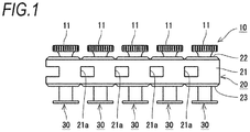
Fig. 1 is a side view of a connection fastener; -
Fig. 2A is a partial sectional view of the connection fastener, andFig. 2B is a sectional view of a conventional connection fastener; -
Fig. 3A is a development view of a connection band (a connection portion), andFig. 3B is a side view of the connection band (the connection portion); -
Fig. 4A is a top view of a tubular member (an attaching portion), andFig. 4B is a sectional view of the tubular member (the attaching portion); -
Figs. 5A and 5B are views illustrating postures during driving; whereinFig. 5A is a view when the tubular member is present andFig. 5B is a view when the tubular member is not present; -
Figs. 6A to 6D are views illustrating postures during driving according to the present embodiment; whereinFig. 6A is a view before a fastener comes into contact with a driver,Fig. 6B is a view just after the fastener comes into contact with the driver,Fig. 6C is a view of a state in which the tubular member is removed from the connection band, andFig. 6D is a view of a state in which the fastener is severed from the connection band; -
Figs. 7A and 7C are views illustrating postures during driving when the tubular member is formed integrally with the connection band; whereinFig. 7A is a view before the fastener comes into contact with a driver,Fig. 7B is a view just after the fastener comes into contact with the driver, andFig. 7C is a view of a state in which the tubular member is severed from the connection band; -
Figs. 8A and 8B are views according to a modification; whereinFig. 8A is a partial sectional view of the connection fastener in which a short fastener is used andFig. 8B is a partial sectional view of the connection fastener in which the connection band is pressed by a flange portion; -
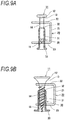
Figs. 9A and 9B are views according to a modification; whereinFig. 9A is a partial sectional view of the connection fastener in which a nail is used andFig. 9B is a partial sectional view of the connection fastener in which a screw is used; -
Figs. 10A to 10C are views according to a modification in which the tubular member without a flange portion is used; whereinFig. 10A is a partial sectional view of the connection fastener in which a short fastener is used,Fig. 10B is a partial sectional view of the connection fastener in which a fastener having a medium length is used, andFig. 10C is a partial sectional view of the connection fastener in which a long fastener is used; -
Figs. 11A to 11E are views according to a modification; whereinFig. 11A is a partial sectional view of the connection fastener having an fall-preventing shape of a tapered shape,Fig. 11B is a partial sectional view of the connection fastener having an fall-preventing shape of a stepped shape,Fig. 11C is a partial sectional view of the connection fastener having an fall-preventing shape of a concave shape,Fig. 11D is a partial sectional view of the connection fastener having an fall-preventing shape of a bulgy shape, andFig. 11E is a partial sectional view of the connection fastener having an fall-preventing shape of a large diameter shape; and -
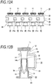
Figs. 12A and 12B are views according to a modification; whereinFig. 12A is a side view of the connection fastener in which a stepped portion is provided for the tubular member, andFig. 12B is a partial sectional view of the connection fastener in which the stepped portion is provided for the tubular member. - A
connection fastener 10 according to the present embodiment will be described with reference to the drawings. - As illustrated in
Fig. 1 , theconnection fastener 10 according to the present embodiment is configured to connect a plurality offasteners 11 with a connection band (a connection portion) 20, so that a great deal offasteners 11 can be set for a driving tool en bloc and be continuously injected. Although particularly not illustrated, the driving tool is provided with a magazine for containing theconnection fastener 10, and a feed mechanism for feeding theconnection fastener 10 stored in the magazine to a leading end portion of a tool main body thereof. The feed mechanism is linked to a driving motion and feeds theconnection fastener 10 one by one, thereby setting thefastener 11 in the forefront of theconnection fastener 10 for aninjection path 40 provided at the leading end portion of the tool main body. Thefastener 11 set for theinjection path 40 in this way is driven out by adriver 41 operated by a striking mechanism of the driving tool. Thefastener 11 driven out by thedriver 41 passes through theinjection path 40 and is injected from an injection port provided at the leading end portion of the tool main body. - The
connection fastener 10 according to the present embodiment arranges and connects thefasteners 11 in parallel (in a parallel direction) such that a line connecting the centers of thefasteners 11 becomes a straight line. Thereby, theconnection fastener 10 is formed in a straight band shape. - The
fastener 11 according to the present embodiment is a concrete pin that is driven into, for instance, concrete or a siding member, and is, as illustrated inFig. 2A , provided with ahead portion 12, an under-head taperedportion 13 that is continuous to thehead portion 12, ashank 14 that is continuous to the under-head taperedportion 13, and a taperedleading end portion 15 that is continuous to theshank 14. Thehead portion 12 is a discoid region being subject to the driving of thedriver 41. The under-head taperedportion 13 is for smoothly connecting thehead portion 12 and theshank 14, and is a region whose diameter is gradually reduced in a direction from thehead portion 12 to theshank 14. Theshank 14 is a region that is formed in a columnar shape and generates pullout resistance when driven into a driven material. Theleading end portion 15 is a region that is formed in a pointed shape and is pierced into a driven material. In the present embodiment, theleading end portion 15 is formed in a shell shape. - The
fastener 11 may have a shape with a head portion, a shank of a gently tapered shape that is continuous to the head portion (wherein an under-head tapered portion that is continuous to the head portion may be present between the head portion and the shank), and a tapered leading end portion that is continuous to the shank. - A stepped
portion 14a for reducing penetration resistance is continuously formed at theshank 14 of thefastener 11 according to the present embodiment. For this reason, a diameter of theshank 14 is configured such that, in comparison with a diameter of a straight portion closer to thehead portion 12 than the steppedportion 14a, a diameter of a straight portion closer to theleading end portion 15 than the steppedportion 14a is smaller. - A
cylindrical member 30 acting as a tubular member (an attaching portion) is attached to theshank 14 of thefastener 11. Thecylindrical member 30 is a member formed of aluminum or a synthetic resin and, as illustrated inFigs. 4A and 4B , includes atubular portion 31 and aflange portion 33 formed to protrude from an opening edge of thetubular portion 31. - The
flange portion 33 may protrude below alower holding portion 23 in an outer circumferential direction or be provided at a position other than the opening edge. For example, theflange portion 33 may be formed on an outer circumferential surface of thetubular portion 31 to protrude in a radial direction. - In addition, the
flange portion 33 may be formed separately from and independently of thetubular portion 31. A shape of theflange portion 33 is not limited to a circular shape as shown inFig. 4A , but it may be a shape in which an outer circumference is on a cylindrical locus. For example, the shape of theflange portion 33 may be a polygonal shape or a rectangular shape having a cutout portion. Similarly, a shape of thecylindrical member 30 is not also limited to a circular shape, but it may be a tubular shape in which an inner circumference is on a cylindrical locus. For example, thecylindrical member 30 may be a tubular member having a polygonal shape or a rectangular shape which forms a cutout portion such that the tubular member covers at least one part of theshank 14. - An inner diameter of the
tubular portion 31 is formed in such a size as to be able to forcibly insert theshank 14 of the fastener 11 (which is closer to theleading end portion 15 than the steppedportion 14a). Theleading end portion 15 of thefastener 11 is inserted into thetubular portion 31, and thereby thecylindrical member 30 can be attached to thefastener 11. In the present embodiment, as illustrated inFig. 2A , thefastener 11 can be inserted up to a position where the steppedportion 14a reaches anupper edge portion 32 of thecylindrical member 30, and an inserted position of thecylindrical member 30 into thefastener 11 is configured to be determined by the steppedportion 14a, so that assemblability is good. - The
connection band 20 connecting thefasteners 11 is a sheet-shaped member as shown inFigs. 3A and 3B , and is formed of a synthetic resin in the present embodiment. Although it is shown in the figure that theconnection band 20 is short in length, theconnection band 20 is actually formed from one long sheet in which the same shape is continuous in a vertical direction ofFig. 3A . - This
connection band 20 is provided with upper holding portions (first holding portions) 22, each of which holds thehead portion 12 side of thefastener 11, lower holding portions (second holding portions) 23, each of which supports and holds thecylindrical member 30 attached to thefastener 11, and a band-shapedportion 21 that connects theupper holding portions 22 and thelower holding portions 23. Theupper holding portions 22 and thelower holding portions 23 are provided by the same number to be correspond to each other, and onefastener 11 is configured to be held by a pair of corresponding upper andlower holding portions portion 21 runs in a longitudinal direction to connect all of the upper andlower holding portions - In this
connection band 20, theupper holding portions 22, thelower holding portions 23, and the band-shapedportion 21 are formed on the same plane, and afolding groove 20a is formed between theupper holding portions 22 and the band-shapedportion 21 and between thelower holding portions 23 and the band-shapedportion 21. Theconnection band 20 is folded along thefolding groove 20a. Thereby, as illustrated inFig. 2A , theconnection band 20 formed from one long sheet is deformed in a C shape to support and hold thefasteners 11. - As illustrated in
Fig. 2A , the upper holdingportion 22 supports and holds the top of theshank 14 of thefastener 11. As illustrated inFig. 3A , the upper holdingportion 22 is provided with anupper slit 22a whose width is narrower than a maximum diameter of theshank 14 of thefastener 11, and an upper holding hole (a first holding hole) 22b that is provided behind theupper slit 22a. A diameter of theupper holding hole 22b is greater than the maximum diameter of theshank 14 of thefastener 11. Theupper slit 22a is provided as an opening edge of theupper holding hole 22b, and communicates with theupper holding hole 22b. - As illustrated in
Fig. 2A , thelower holding portion 23 supports and holds thetubular portion 31 of thecylindrical member 30. Additionally, thelower holding portion 23 may be configured to support and hold at least one part of a circumferential surface of thecylindrical member 30. As illustrated inFig. 3A , thelower holding portion 23 is provided with alower slit 23a whose width is narrower than a diameter of thetubular portion 31 of thecylindrical member 30, and a lower holding hole (a second holding hole) 23b that is provided behind thelower slit 23a. A diameter of thelower holding hole 23b is greater than the diameter of thetubular portion 31 of thecylindrical member 30. Thelower slit 23a is provided as an opening edge of thelower holding hole 23b, and communicates with thelower holding hole 23b. - At this time, the width DW1 of the
lower slit 23a (an opening width of the opening slit (opening edge) of thelower holding hole 23b) is formed to be greater than the width UW1 of theupper slit 22a (an opening width of the opening slit (opening edge) of theupper holding hole 22b), and a diameter DW2 of thelower holding hole 23b is formed to be greater than a diameter UW2 of theupper holding hole 22b. - With this formation, an inner diameter of the
lower holding hole 23b is increased depending on a lower portion of thefastener 11 which is thickened by the amount of attaching thecylindrical member 30, and thefastener 11 can be stably held. - When the
fastener 11 is loaded on theconnection band 20, theshank 14 of thefastener 11 is loaded from theupper slit 22a to theupper holding hole 22b, and thecylindrical member 30 is loaded from thelower slit 23a to thelower holding hole 23b. At this time, since the width DW1 of thelower slit 23a is increased depending on the lower portion of thefastener 11 which is thickened by the amount of attaching thecylindrical member 30, thefastener 11 can be loaded and held without difficulty, and the assemblability is good. - Even when the
fastener 11 is driven, since the width DW1 of the lower slit 23 a is great, thefastener 11 can be smoothly removed from theconnection band 20. - Meanwhile, as illustrated in
Fig. 3A , feedingholes 21a are formed in the band-shapedportion 21 of theconnection band 20 at the same intervals as those at which thefasteners 11 are held. The feeding holes 21a are intended for use of the feed mechanism of the driving tool. That is, the feed mechanism is operated with feed claws thereof engaged with thefeeding holes 21a, and thereby thefasteners 11 are configured to be fed to theinjection path 40 in turn. A width of the band-shapedportion 21 having these feedingholes 21a (a length H1 of the band-shapedportion 21 when viewed in an axial direction of the fastener 11) (seeFig. 2A ) is regulated by the driving tool, and cannot be easily changed. For example, when the length H1 of the band-shapedportion 21 is reduced, the feed mechanism cannot normally perform the feed operation. Therefore, the length H1 of the band-shapedportion 21 cannot be changed. However, a structure of the related art has a problem that, since the length H1 of the band-shapedportion 21 cannot be reduced,short fasteners 11 cannot be held by theconnection band 20. - For example, in the present embodiment, as illustrated in
Fig. 2A , when viewed in the axial direction of thefastener 11, a length H2 of theshank 14 of thefastener 11 is configured to be shorter than the length H1 of the band-shapedportion 21 of theconnection band 20. - For this reason, the
lower holding portion 23 is located at a position at which it overlaps theleading end portion 15 of thefastener 11. When thisshort fastener 11 is to be held in the structure of the related art, there is a possibility of thelower holding portion 23 falling out of theleading end portion 15 of thefastener 11 as illustrated inFig. 2B , and thefastener 11 cannot be reliably held. In this regard, according to the present embodiment, since thecylindrical member 30 is attached to thefastener 11, and since thelower holding portion 23 supports and holds thecylindrical member 30, the upper and lower portions of thefastener 11 can be reliably held. Therefore, theshort fastener 11 limited by specifications of the tool so far can be used, and buckling during driving can be prevented because the driving posture of thefastener 11 is stable. - In the present embodiment, as illustrated in
Fig. 5A , when thefastener 11 is driven by thedriver 41 within theinjection path 40 of the driving tool, thefastener 11 moves within theinjection path 40 with thecylindrical member 30 attached to a toe of thefastener 11. For this reason, a tilt of thefastener 11 is suppressed. When thecylindrical member 30 is not present, thefastener 11 is inclined within theinjection path 40 and is obliquely driven as illustrated inFig. 5B , which is attributed to the buckling or the like of thefastener 11. In this way, as thecylindrical member 30 is attached to the toe (theleading end portion 15 side) of thefastener 11, theconnection fastener 10 according to the present embodiment is configured to be able to prevent the buckling during driving. - In the present embodiment, since the
cylindrical member 30 is provided separately from and independently of theconnection band 20, there is no need to sever thecylindrical member 30 from theconnection band 20 during driving of thefastener 11. For this reason, when thefastener 11 is driven by thedriver 41 within theinjection path 40 of the driving tool, thecylindrical member 30 is removed from theconnection band 20 as illustrated inFigs. 6A to 6D , but thecylindrical member 30 is not pulled and inclined by theconnection band 20. Therefore, thefastener 11 can be prevented from being inclined and buckled. Energy is not lost in order to cut theconnection band 20. - When the
cylindrical member 30 is provided as a part of theconnection band 20, thecylindrical member 30 is pulled by theconnection band 20 when severed from theconnection band 20 as illustrated inFigs. 7A to 7C , so that thecylindrical member 30 is inclined. For this reason, there is a possibility of thefastener 11 being inclined and buckled. The loss of energy to cut theconnection band 20 is caused. In this regard, when theconnection band 20 and thecylindrical member 30 are separately provided as in the present embodiment, this problem does not occur. - In the above embodiment, the example in which the
lower holding portion 23 supports and holds thecylindrical member 30 at a position at which it overlaps theleading end portion 15 of thefastener 11 when viewed from a side direction of thefastener 11 has been described. In other words, thelower holding portion 23 supports and holds thecylindrical member 30 at a position at which the taperedleading end portion 15 of thefasteners 11 reaches thelower holding portion 23 in the axial direction of thefasteners 11. But, the embodiment is not limited thereto. As illustrated inFig. 8A , thelower holding portion 23 may be configured to support and hold thecylindrical member 30 at a position at which it does not overlap thefastener 11 when viewed from a side direction of thefastener 11. In other words, thelower holding portion 23 supports and holds thecylindrical member 30 at a position at which the taperedleading end portion 15 of thefasteners 11 does not reach thelower holding portion 23 in the axial direction of thefasteners 11. Even when the veryshort fastener 11 is used in this way, thefastener 11 is lengthened by thecylindrical member 30, and thereby thefastener 11 can be stably held. - As illustrated in
Fig. 8B , theflange portion 33 of thecylindrical member 30 may be disposed to make it possible to come into contact with a lower portion of thelower holding portion 23. Thereby, since spreading of thelower holding portion 23 can be suppressed by theflange portion 33, thelower holding portion 23 can be prevented from being removed from thecylindrical member 30. - In the above embodiment, the concrete pin has been described as the
fastener 11 by way of example, but the embodiment is not limited thereto. For example, as illustrated inFig. 9A , a nail may be used as thefastener 11. In addition, as illustrated inFig. 9B , a screw may be used as thefastener 11. - In the above embodiment, the
flange portion 33 is provided for thecylindrical member 30, but the embodiment is not limited thereto. As illustrated inFig. 10A , theflange portion 33 may not be provided for thecylindrical member 30. In addition, as illustrated inFigs. 10B and 10C , along fastener 11 may be used. - As illustrated in
Figs. 11A to 11E , a fall-preventing shape for preventing thelower holding portion 23 from falling off may be provided for thecylindrical member 30. - For example, as illustrated in
Fig. 11A , thetubular portion 31 of thecylindrical member 30 has a taperedshape 34 whose diameter is gradually increased in a direction of a leading end portion thereof, and the taperedshape 34 is held by thelower holding portion 23. Thereby, a fall-preventing shape for preventing thelower holding portion 23 from falling off may be formed. In this configuration, besides being able to preventing thelower holding portion 23 from falling off, when thefastener 11 is loaded on theconnection band 20, an inserted position of thelower holding portion 23 of theconnection band 20 can depend on the taperedshape 34, and thus the assemblability can be improved. When thefastener 11 is driven, thecylindrical member 30 of the taperedshape 34 falls off from thelower holding portion 23 as it is, and thus thefastener 11 can be smoothly removed from theconnection band 20. - As illustrated in
Fig. 11B , a steppedshape 35 having a large diameter is formed at a leading end portion side of thetubular portion 31 of thecylindrical member 30, and thelower holding portion 23 is engaged with this steppedshape 35. Thereby, thetubular portion 31 of thecylindrical member 30 may be formed in the fall-preventing shape for preventing thelower holding portion 23 from falling off. In this configuration, besides being able to preventing thelower holding portion 23 from falling off, when thefastener 11 is loaded on theconnection band 20, the inserted position of thelower holding portion 23 of theconnection band 20 can depend on the steppedshape 35, and thus the assemblability can be improved. - As illustrated in
Fig. 11C , aconcave shape 36 is formed at thetubular portion 31 of thecylindrical member 30 in a circumferential groove shape, and thelower holding portion 23 is engaged with thisconcave shape 36. Thereby, thetubular portion 31 of thecylindrical member 30 may be formed in the fall-preventing shape for preventing thelower holding portion 23 from falling off. In this configuration, besides being able to preventing thelower holding portion 23 from falling off, when thefastener 11 is loaded on theconnection band 20, the inserted position of thelower holding portion 23 of theconnection band 20 can depend on theconcave shape 36, and thus the assemblability can be improved. - As illustrated in
Fig. 11D , abulgy shape 37 swollen in an outer circumferential direction is provided at the leading end portion side of thetubular portion 31 of thecylindrical member 30, and thelower holding portion 23 is engaged with thisbulgy shape 37. Thereby, thetubular portion 31 of thecylindrical member 30 may be formed in the fall-preventing shape for preventing thelower holding portion 23 from falling off. In this configuration, besides being able to preventing thelower holding portion 23 from falling off, when thefastener 11 is loaded on theconnection band 20, the inserted position of thelower holding portion 23 of theconnection band 20 can depend on thebulgy shape 37, and thus the assemblability can be improved. - As illustrated in
Fig. 11E , alarge diameter shape 38 is formed by making a large diameter for the leading end portion side of thetubular portion 31 of thecylindrical member 30, and thelarge diameter shape 38 is held by thelower holding portion 23. Thereby, thetubular portion 31 of thecylindrical member 30 may be formed in the fall-preventing shape for preventing thelower holding portion 23 from falling off. In this configuration, besides being able to preventing thelower holding portion 23 from falling off, when thefastener 11 is loaded on theconnection band 20, the inserted position of thelower holding portion 23 of theconnection band 20 can depend on thelarge diameter shape 38, and thus the assemblability can be improved. - As illustrated in
Figs. 12A and 12B , a steppedportion 39 may be provided at thetubular portion 31 of thecylindrical member 30. By providing this steppedportion 39, a leading end portion side of the steppedportion 39 is formed to be larger in diameter than a trailing end portion side of the steppedportion 39. This steppedportion 39 is disposed closer to the toe side (theleading end portion 15 side) of thefastener 11 than thelower holding portion 23, and is configured not to be contact with thelower holding portion 23. Even in this configuration, as in the form shown inFig. 11B , thelower holding portion 23 can be inhibited from being spread by the steppedportion 39, and thetubular portion 31 of thecylindrical member 30 can be formed in the fall-preventing shape for preventing thelower holding portion 23 from falling off. - In the example shown in
Figs. 12A and 12B , the steppedportion 39 is formed by corners whose cross sections are formed at a right angle. In this way, the corners of the steppedportion 39 are formed at a right angle, and thereby thelower holding portion 23 is easily caught, and thus an effect of preventing the spread of thelower holding portion 23 can be enhanced. However, the corners of the steppedportion 39 are not limited to the right angle, and may have an R shape as small as possible. - As described above, according to the present embodiment, the
connection band 20 including thecylindrical member 30 attached to thefastener 11 is provided with theupper holding portions 22, each of which supports and holds thehead portion 12 side of thefastener 11, and thelower holding portions 23, each of which supports and holds thecylindrical member 30 attached to thefastener 11. According to this configuration, since thefasteners 11 are stretched by thecylindrical members 30 and are held by thelower holding portions 23, even when the width of theconnection band 20 is regulated by the tool, thefasteners 11 can be stably supported regardless of the lengths of thefasteners 11. - Since the
cylindrical members 30 are members which are separate from and are independent of theconnection band 20, thecylindrical members 30 are not pulled and inclined by theconnection band 20 when removed from theconnection band 20. Therefore, thefasteners 11 can be prevented from being inclined and buckled. No energy is lost to cut theconnection band 20. - The
cylindrical member 30 that is more easily stabilized in dimensional precision than thefastener 11 formed of a metal is used. Thereby, dimensions of thecylindrical member 30 and dimensions of thelower holding portion 23 can be made compatible with each other, and a holding force of thefastener 11 held via thecylindrical member 30 by thelower holding portion 23 can be enhanced. - The
cylindrical member 30 is attached to thefastener 11, and thereby the diameter of the toe side (theleading end portion 15 side) of thefastener 11 is increased. For this reason, thefastener 11 is prevented from falling within theinjection path 40 during driving. Therefore, it is possible to stabilize the driving posture of thefastener 11 to prevent the buckling. - The diameter of the
lower holding hole 23b holding thecylindrical member 30 provided at thelower holding portion 23 is larger than that of theupper holding hole 22b holding thehead portion 12 side of thefastener 11 provided at the upper holdingportion 22. According to this configuration, theshank 14 of thefastener 11 is held by theupper holding hole 22b having a relatively small diameter, and thecylindrical member 30 is held by thelower holding hole 23b having a relatively large diameter. Thus, thefastener 11 can be tightly held even at the lower portion thickened by the amount of attaching thecylindrical member 30. - The
lower holding portion 23 supports and holds thecylindrical member 30 at a position at which it overlaps the taperedleading end portion 15 of thefastener 11 or at a position at which it does not overlap thefastener 11. According to this configuration, even in theshort fastener 11 located at the position at which thelower holding portion 23 overlaps theleading end portion 15 of thefastener 11 or at the position at which thelower holding portion 23 does not overlap thefastener 11, thisshort fastener 11 is stretched by thecylindrical member 30, and is held by thelower holding portion 23. Thus, thefastener 11 can be stably held. - When viewed in the axial direction of the
fastener 11, the length H2 of theshank 14 is shorter than the length H1 of the band-shapedportion 21. According to this configuration, even in theshort fastener 11 in which the length H2 of theshank 14 is shorter than the length H1 of the band-shapedportion 21, thisshort fastener 11 is stretched by thecylindrical member 30, and is held by thelower holding portion 23. Thus, thefastener 11 can be stably held. - The
cylindrical member 30 includes theflange portion 33 that faces the lower portion of thelower holding portion 23 and is formed to protrude in a radial direction of the outer circumference of thecylindrical member 30. According to this configuration, since thelower holding portion 23 is prevented from falling off by theflange portion 33, thelower holding portion 23 is prevented from being removed from thecylindrical member 30. - The
flange portion 33 is provided, and thereby the diameter of the toe side of thefastener 11 is increased. Thus, an effect of preventing thefastener 11 from falling within theinjection path 40 during driving can be enhanced. Therefore, it is possible to stabilize the driving posture of thefastener 11 to prevent the buckling. - The
fastener 11 includes the steppedportion 14a at theshank 14, and the steppedportion 14a is formed such that the outer diameter thereof close to theleading end portion 15 is smaller than that close to thehead portion 12, and faces theupper edge portion 32 of thecylindrical member 30. According to this configuration, when thecylindrical member 30 is attached to thefastener 11, the position of thecylindrical member 30 depends on the steppedportion 14a, and thus a problem that the attached position of thecylindrical member 30 to thefastener 11 is made too shallow or too deep can be avoided. - The
cylindrical member 30 includes the fall-preventing shape for preventing thelower holding portion 23 from falling off. According to this configuration, since thelower holding portion 23 is prevented from falling off by the fall-preventing shape, thelower holding portion 23 is prevented from being removed from thecylindrical member 30. - When the fall-preventing shape is provided for the
fastener 11, there is a problem that the penetration resistance of thefastener 11 is increased or that thefastener 11 is easily buckled. However, the fall-preventing shape is provided for thecylindrical member 30, and thereby such a problem does not occur. - (1) A connection fastener includes:
- a plurality of fasteners each of which includes a head portion provided at one end portion side and a tapered leading end portion provided at the other end portion side;
- a sheet-shaped connection portion that is configured to connect the plurality of fasteners in a parallel direction; and
- attaching portions that are separate from the connection portion attached to the fasteners such that each attaching portion covers at least one part of each leading end portion,
- wherein the connection portion includes:
- first holding portions each of which is configured to support a head portion side of each fastener; and
- second holding portions each of which is configured to support at least one part of a circumferential surface of each attaching portion.
- (2) The connection fastener according to (1), wherein:
- the connection portion includes second holding holes which support the attaching portions provided at the second holding portions, and first holding holes which support the head portion sides of the fasteners provided at the first holding portions; and
- diameters of the second holding holes are larger than diameters of the first holding holes.
- (3) The connection fastener according to (1) or (2), wherein:
- the connection portion includes second holding holes which support the attaching portions provided at the second holding portions, and first holding holes which support the head portion sides of the fasteners provided at the first holding portions; and
- opening widths of opening slits of the second holding holes are larger than opening widths of opening slits of the first holding holes.
- (4) The connection fastener according to any one of (1) to (3), wherein:
- each of the fasteners includes a shank continuously provided between the head portion and the leading end portion; and
- the second holding portions support the attaching portions at positions at which the second holding portions overlap the tapered leading end portions of the fasteners or at positions at which the second holding portions do not overlap the fasteners, when viewed from a side direction of the fastener.
- (5) The connection fastener according to any one of (1) to (4), wherein:
- the connection portion is formed by bending one long sheet in a C shape;
- the first holding portions, the second holding portions, and a band-shaped portion connecting the first holding portions and the second holding portions are formed on the same plane in the long sheet;
- each of the fasteners includes a shank continuously provided between the head portion and the leading end portion; and
- in an axial direction of the fastener, a length of the shank is shorter than a length of the band-shaped portion.
- (6) The connection fastener according to (5), wherein:
- each fastener includes a stepped portion at the shank; and
- the stepped portion is formed such that an outer diameter of a leading end portion side is smaller than an outer diameter of the head portion side, and faces an upper edge portion of the attaching portion.
- (7) The connection fastener according to any one of (1) to (6), wherein
each of the attaching portions includes a flange portion protruding in an outer circumferential direction below the second holding portion. - (8) The connection fastener according to any one of (1) to (7), wherein
each of the attaching portions includes a fall-preventing shape for preventing the second holding portion from falling off. - (9) The connection fastener according to (8), wherein the fall-preventing shape is a tapered shape which diameter is gradually increased toward a leading end portion side of the fastener.
- (10) The connection fastener according to (8), wherein the fall-preventing shape is a stepped shape formed by making a large diameter of the attaching portion in a leading end portion side of the fastener or a concave shape of a circumferential groove shape.
- (11) The connection fastener according to (8), wherein the fall-preventing shape is a bulgy shape in which the attaching portion in the head side of the fastener is swollen in an outer circumferential direction or a large diameter shape formed by making a large diameter of the attaching portion in the head side of the fastener.
Claims (11)
- A connection fastener comprising:a plurality of fasteners each of which includes a head portion provided at one end portion side and a tapered leading end portion provided at the other end portion side;a sheet-shaped connection portion that is configured to connect the plurality of fasteners in a parallel direction; andattaching portions that are separate from the connection portion attached to the fasteners such that each attaching portion covers at least one part of each leading end portion,wherein the connection portion includes:first holding portions each of which is configured to support a head portion side of each fastener; andsecond holding portions each of which is configured to support at least one part of a circumferential surface of each attaching portion.
- The connection fastener according to claim 1, wherein:the connection portion includes second holding holes which support the attaching portions provided at the second holding portions, and first holding holes which support the head portion sides of the fasteners provided at the first holding portions; anddiameters of the second holding holes are larger than diameters of the first holding holes.
- The connection fastener according to claim 1 or 2, wherein:the connection portion includes second holding holes which support the attaching portions provided at the second holding portions, and first holding holes which support the head portion sides of the fasteners provided at the first holding portions; andopening widths of opening slits of the second holding holes are larger than opening widths of opening slits of the first holding holes.
- The connection fastener according to any one of claims 1 to 3, wherein:each of the fasteners includes a shank continuously provided between the head portion and the leading end portion; andthe second holding portions support the attaching portions at positions at which the second holding portions overlap the tapered leading end portions of the fasteners or at positions at which the second holding portions do not overlap the fasteners, when viewed from a side direction of the fastener.
- The connection fastener according to any one of claims 1 to 4, wherein:the connection portion is formed by bending one long sheet in a C shape;the first holding portions, the second holding portions, and a band-shaped portion connecting the first holding portions and the second holding portions are formed on the same plane in the long sheet;each of the fasteners includes a shank continuously provided between the head portion and the leading end portion; andin an axial direction of the fastener, a length of the shank is shorter than a length of the band-shaped portion.
- The connection fastener according to claim 5, wherein:each fastener includes a stepped portion at the shank; andthe stepped portion is formed such that an outer diameter of a leading end portion side is smaller than an outer diameter of the head portion side, and faces an upper edge portion of the attaching portion
- The connection fastener according to any one of claim 1 to 6, wherein
each of the attaching portions includes a flange portion protruding in an outer circumferential direction below the second holding portion. - The connection fastener according to any one of claims 1 to 7, wherein
each of the attaching portions includes a fall-preventing shape for preventing the second holding portion from falling off. - The connection fastener according to claim 8, wherein the fall-preventing shape is a tapered shape which diameter is gradually increased toward a leading end portion side of the fastener.
- The connection fastener according to claim 8, wherein the fall-preventing shape is a stepped shape formed by making a large diameter of the attaching portion in a leading end portion side of the fastener or a concave shape of a circumferential groove shape.
- The connection fastener according to claim 8, wherein the fall-preventing shape is a bulgy shape in which the attaching portion in the head side of the fastener is swollen in an outer circumferential direction or a large diameter shape formed by making a large diameter of the attaching portion in the head side of the fastener.
Priority Applications (1)
| Application Number | Priority Date | Filing Date | Title |
|---|---|---|---|
| PL17181391T PL3269987T3 (en) | 2016-07-15 | 2017-07-14 | Connection fastener |
Applications Claiming Priority (2)
| Application Number | Priority Date | Filing Date | Title |
|---|---|---|---|
| JP2016139922 | 2016-07-15 | ||
| JP2017096995A JP6897302B2 (en) | 2016-07-15 | 2017-05-16 | Connecting fastener |
Publications (2)
| Publication Number | Publication Date |
|---|---|
| EP3269987A1 true EP3269987A1 (en) | 2018-01-17 |
| EP3269987B1 EP3269987B1 (en) | 2021-09-08 |
Family
ID=59362967
Family Applications (1)
| Application Number | Title | Priority Date | Filing Date |
|---|---|---|---|
| EP17181391.8A Active EP3269987B1 (en) | 2016-07-15 | 2017-07-14 | Connection fastener |
Country Status (5)
| Country | Link |
|---|---|
| US (1) | US10428853B2 (en) |
| EP (1) | EP3269987B1 (en) |
| KR (1) | KR102242482B1 (en) |
| ES (1) | ES2892752T3 (en) |
| PL (1) | PL3269987T3 (en) |
Cited By (2)
| Publication number | Priority date | Publication date | Assignee | Title |
|---|---|---|---|---|
| TWI689667B (en) * | 2019-06-24 | 2020-04-01 | 光柘企業有限公司 | Screw carrier tape |
| US11624391B2 (en) | 2018-12-27 | 2023-04-11 | Max Co., Ltd. | Connection fastener |
Families Citing this family (1)
| Publication number | Priority date | Publication date | Assignee | Title |
|---|---|---|---|---|
| US10816025B1 (en) * | 2019-08-23 | 2020-10-27 | Guangzhe Enterprise Co., Ltd. | Screw band |
Citations (5)
| Publication number | Priority date | Publication date | Assignee | Title |
|---|---|---|---|---|
| US4915561A (en) * | 1987-12-18 | 1990-04-10 | Hilti Aktiengesellschaft | Fastening element assembly with a deformable sleeve |
| JPH0396417A (en) | 1989-09-08 | 1991-04-22 | Mazda Motor Corp | Air conditioner for vehicle |
| JP2002081424A (en) * | 2000-09-07 | 2002-03-22 | Sakai Fastening:Kk | Concrete pin and manufacturing method therefor |
| US6779959B1 (en) * | 2003-04-21 | 2004-08-24 | Testo Industry Corp. | Belt of nails for nailers |
| EP2258954A1 (en) * | 2008-03-31 | 2010-12-08 | Max Co., Ltd. | Connected fasteners |
Family Cites Families (14)
| Publication number | Priority date | Publication date | Assignee | Title |
|---|---|---|---|---|
| US2203294A (en) * | 1939-03-16 | 1940-06-04 | Ralph L Engle | Nail for fastening sheeting |
| CA960189A (en) * | 1971-07-12 | 1974-12-31 | Hilti Aktiengesellschaft | Nail holder assembly |
| US4606455A (en) * | 1984-08-17 | 1986-08-19 | Duo-Fast Corporation | Collated fastener strip |
| US5178903A (en) * | 1989-09-29 | 1993-01-12 | Illinois Tool Works Inc. | Coated metal fastener and method for making same |
| JPH0637203Y2 (en) | 1990-01-23 | 1994-09-28 | 若井産業株式会社 | Interlocking nail tape |
| JPH07100208B2 (en) * | 1992-10-15 | 1995-11-01 | 大内 正年 | Blind rivet holder |
| JP3429202B2 (en) * | 1998-08-11 | 2003-07-22 | 株式会社パイオラックス | Clip for fixing panel-shaped parts |
| CA2292166A1 (en) * | 1999-01-13 | 2000-07-13 | Kent B. Godsted | Chemically coated fasteners having improved penetration and withdrawal resistance |
| US7273337B2 (en) * | 2003-06-30 | 2007-09-25 | Illinois Tool Works Inc. | Partially coated fastener assembly and method for coating |
| ITBO20070658A1 (en) * | 2007-09-27 | 2009-03-28 | Samp S P A | EXTRUSION SCREW FOR MACHINES TO EXTRUDE PLASTIC MATERIAL. |
| TWI530623B (en) * | 2007-11-06 | 2016-04-21 | 美克司股份有限公司 | Connected fastener assembly |
| JP2010265952A (en) * | 2009-05-13 | 2010-11-25 | Nifco Inc | Fastener |
| US20120298716A1 (en) * | 2011-05-23 | 2012-11-29 | Ricardo Segura | Fastener collation having a collation of frangible fastener alignment caps |
| US20130270135A1 (en) * | 2012-04-13 | 2013-10-17 | Ching Yun Huang | Strip for supporting fasteners |
-
2017
- 2017-07-13 KR KR1020170088885A patent/KR102242482B1/en active Active
- 2017-07-13 US US15/648,818 patent/US10428853B2/en active Active
- 2017-07-14 PL PL17181391T patent/PL3269987T3/en unknown
- 2017-07-14 EP EP17181391.8A patent/EP3269987B1/en active Active
- 2017-07-14 ES ES17181391T patent/ES2892752T3/en active Active
Patent Citations (5)
| Publication number | Priority date | Publication date | Assignee | Title |
|---|---|---|---|---|
| US4915561A (en) * | 1987-12-18 | 1990-04-10 | Hilti Aktiengesellschaft | Fastening element assembly with a deformable sleeve |
| JPH0396417A (en) | 1989-09-08 | 1991-04-22 | Mazda Motor Corp | Air conditioner for vehicle |
| JP2002081424A (en) * | 2000-09-07 | 2002-03-22 | Sakai Fastening:Kk | Concrete pin and manufacturing method therefor |
| US6779959B1 (en) * | 2003-04-21 | 2004-08-24 | Testo Industry Corp. | Belt of nails for nailers |
| EP2258954A1 (en) * | 2008-03-31 | 2010-12-08 | Max Co., Ltd. | Connected fasteners |
Cited By (3)
| Publication number | Priority date | Publication date | Assignee | Title |
|---|---|---|---|---|
| US11624391B2 (en) | 2018-12-27 | 2023-04-11 | Max Co., Ltd. | Connection fastener |
| EP3674569B1 (en) * | 2018-12-27 | 2025-05-21 | Max Co., Ltd. | Connection fastener |
| TWI689667B (en) * | 2019-06-24 | 2020-04-01 | 光柘企業有限公司 | Screw carrier tape |
Also Published As
| Publication number | Publication date |
|---|---|
| US20180017093A1 (en) | 2018-01-18 |
| ES2892752T3 (en) | 2022-02-04 |
| KR20180008312A (en) | 2018-01-24 |
| PL3269987T3 (en) | 2022-01-31 |
| EP3269987B1 (en) | 2021-09-08 |
| KR102242482B9 (en) | 2022-04-14 |
| KR102242482B1 (en) | 2021-04-20 |
| US10428853B2 (en) | 2019-10-01 |
Similar Documents
| Publication | Publication Date | Title |
|---|---|---|
| EP3269987B1 (en) | Connection fastener | |
| US6969220B2 (en) | Wall anchor for a screw, and assembly constituted by such a wall anchor and a screw | |
| TWI571567B (en) | Elongated fastener strip and fastener | |
| JP2787506B2 (en) | Guidance device | |
| JP5895648B2 (en) | Replaceable head cutting tool | |
| CN102493990B (en) | Connected fastener assembly | |
| JPS63210404A (en) | Nail retaining band for piston type driving device | |
| US11149773B2 (en) | Connection fastener | |
| CN101440836B (en) | Connected fastener assembly | |
| US10006251B2 (en) | Digging bit | |
| JP2020016276A (en) | Screw nail and member fixing device | |
| US20250052268A1 (en) | Fastener support, coupled fastener, and manufacturing method of fastener support | |
| WO2016092675A1 (en) | Post-installed anchor, post-installed anchor construction method, and post-installed anchor system | |
| JPS6311522B2 (en) | ||
| JP7290535B2 (en) | Adherent device | |
| US20060234801A1 (en) | Nail with wings on tip | |
| JP6703221B2 (en) | Board anchor construction tool | |
| JPS6326567Y2 (en) | ||
| EP3674569B1 (en) | Connection fastener | |
| JP4179171B2 (en) | Throw-away drill and throw-away tip | |
| JP6075437B2 (en) | Replaceable head cutting tool | |
| JP4747314B2 (en) | Throw-away drill | |
| JP2017129213A (en) | anchor | |
| JPH09177744A (en) | Connecting screw holding belt | |
| JPS61241511A (en) | Insert |
Legal Events
| Date | Code | Title | Description |
|---|---|---|---|
| PUAI | Public reference made under article 153(3) epc to a published international application that has entered the european phase |
Free format text: ORIGINAL CODE: 0009012 |
|
| STAA | Information on the status of an ep patent application or granted ep patent |
Free format text: STATUS: THE APPLICATION HAS BEEN PUBLISHED |
|
| AK | Designated contracting states |
Kind code of ref document: A1 Designated state(s): AL AT BE BG CH CY CZ DE DK EE ES FI FR GB GR HR HU IE IS IT LI LT LU LV MC MK MT NL NO PL PT RO RS SE SI SK SM TR |
|
| AX | Request for extension of the european patent |
Extension state: BA ME |
|
| STAA | Information on the status of an ep patent application or granted ep patent |
Free format text: STATUS: REQUEST FOR EXAMINATION WAS MADE |
|
| 17P | Request for examination filed |
Effective date: 20180424 |
|
| RBV | Designated contracting states (corrected) |
Designated state(s): AL AT BE BG CH CY CZ DE DK EE ES FI FR GB GR HR HU IE IS IT LI LT LU LV MC MK MT NL NO PL PT RO RS SE SI SK SM TR |
|
| GRAP | Despatch of communication of intention to grant a patent |
Free format text: ORIGINAL CODE: EPIDOSNIGR1 |
|
| STAA | Information on the status of an ep patent application or granted ep patent |
Free format text: STATUS: GRANT OF PATENT IS INTENDED |
|
| INTG | Intention to grant announced |
Effective date: 20210507 |
|
| RIN1 | Information on inventor provided before grant (corrected) |
Inventor name: ARAI, TOSHIMICHI Inventor name: NAKAGAWA, YASUSHI |
|
| GRAS | Grant fee paid |
Free format text: ORIGINAL CODE: EPIDOSNIGR3 |
|
| GRAA | (expected) grant |
Free format text: ORIGINAL CODE: 0009210 |
|
| STAA | Information on the status of an ep patent application or granted ep patent |
Free format text: STATUS: THE PATENT HAS BEEN GRANTED |
|
| AK | Designated contracting states |
Kind code of ref document: B1 Designated state(s): AL AT BE BG CH CY CZ DE DK EE ES FI FR GB GR HR HU IE IS IT LI LT LU LV MC MK MT NL NO PL PT RO RS SE SI SK SM TR |
|
| REG | Reference to a national code |
Ref country code: GB Ref legal event code: FG4D |
|
| REG | Reference to a national code |
Ref country code: CH Ref legal event code: EP Ref country code: AT Ref legal event code: REF Ref document number: 1428846 Country of ref document: AT Kind code of ref document: T Effective date: 20210915 |
|
| REG | Reference to a national code |
Ref country code: DE Ref legal event code: R096 Ref document number: 602017045568 Country of ref document: DE |
|
| REG | Reference to a national code |
Ref country code: IE Ref legal event code: FG4D |
|
| REG | Reference to a national code |
Ref country code: FI Ref legal event code: FGE |
|
| REG | Reference to a national code |
Ref country code: DK Ref legal event code: T3 Effective date: 20210929 |
|
| REG | Reference to a national code |
Ref country code: SE Ref legal event code: TRGR |
|
| REG | Reference to a national code |
Ref country code: NL Ref legal event code: FP |
|
| REG | Reference to a national code |
Ref country code: LT Ref legal event code: MG9D |
|
| REG | Reference to a national code |
Ref country code: NO Ref legal event code: T2 Effective date: 20210908 |
|
| PG25 | Lapsed in a contracting state [announced via postgrant information from national office to epo] |
Ref country code: RS Free format text: LAPSE BECAUSE OF FAILURE TO SUBMIT A TRANSLATION OF THE DESCRIPTION OR TO PAY THE FEE WITHIN THE PRESCRIBED TIME-LIMIT Effective date: 20210908 Ref country code: BG Free format text: LAPSE BECAUSE OF FAILURE TO SUBMIT A TRANSLATION OF THE DESCRIPTION OR TO PAY THE FEE WITHIN THE PRESCRIBED TIME-LIMIT Effective date: 20211208 Ref country code: LT Free format text: LAPSE BECAUSE OF FAILURE TO SUBMIT A TRANSLATION OF THE DESCRIPTION OR TO PAY THE FEE WITHIN THE PRESCRIBED TIME-LIMIT Effective date: 20210908 Ref country code: HR Free format text: LAPSE BECAUSE OF FAILURE TO SUBMIT A TRANSLATION OF THE DESCRIPTION OR TO PAY THE FEE WITHIN THE PRESCRIBED TIME-LIMIT Effective date: 20210908 |
|
| REG | Reference to a national code |
Ref country code: ES Ref legal event code: FG2A Ref document number: 2892752 Country of ref document: ES Kind code of ref document: T3 Effective date: 20220204 |
|
| PG25 | Lapsed in a contracting state [announced via postgrant information from national office to epo] |
Ref country code: LV Free format text: LAPSE BECAUSE OF FAILURE TO SUBMIT A TRANSLATION OF THE DESCRIPTION OR TO PAY THE FEE WITHIN THE PRESCRIBED TIME-LIMIT Effective date: 20210908 Ref country code: GR Free format text: LAPSE BECAUSE OF FAILURE TO SUBMIT A TRANSLATION OF THE DESCRIPTION OR TO PAY THE FEE WITHIN THE PRESCRIBED TIME-LIMIT Effective date: 20211209 |
|
| PG25 | Lapsed in a contracting state [announced via postgrant information from national office to epo] |
Ref country code: IS Free format text: LAPSE BECAUSE OF FAILURE TO SUBMIT A TRANSLATION OF THE DESCRIPTION OR TO PAY THE FEE WITHIN THE PRESCRIBED TIME-LIMIT Effective date: 20220108 Ref country code: SM Free format text: LAPSE BECAUSE OF FAILURE TO SUBMIT A TRANSLATION OF THE DESCRIPTION OR TO PAY THE FEE WITHIN THE PRESCRIBED TIME-LIMIT Effective date: 20210908 Ref country code: SK Free format text: LAPSE BECAUSE OF FAILURE TO SUBMIT A TRANSLATION OF THE DESCRIPTION OR TO PAY THE FEE WITHIN THE PRESCRIBED TIME-LIMIT Effective date: 20210908 Ref country code: RO Free format text: LAPSE BECAUSE OF FAILURE TO SUBMIT A TRANSLATION OF THE DESCRIPTION OR TO PAY THE FEE WITHIN THE PRESCRIBED TIME-LIMIT Effective date: 20210908 Ref country code: PT Free format text: LAPSE BECAUSE OF FAILURE TO SUBMIT A TRANSLATION OF THE DESCRIPTION OR TO PAY THE FEE WITHIN THE PRESCRIBED TIME-LIMIT Effective date: 20220110 Ref country code: EE Free format text: LAPSE BECAUSE OF FAILURE TO SUBMIT A TRANSLATION OF THE DESCRIPTION OR TO PAY THE FEE WITHIN THE PRESCRIBED TIME-LIMIT Effective date: 20210908 Ref country code: CZ Free format text: LAPSE BECAUSE OF FAILURE TO SUBMIT A TRANSLATION OF THE DESCRIPTION OR TO PAY THE FEE WITHIN THE PRESCRIBED TIME-LIMIT Effective date: 20210908 Ref country code: AL Free format text: LAPSE BECAUSE OF FAILURE TO SUBMIT A TRANSLATION OF THE DESCRIPTION OR TO PAY THE FEE WITHIN THE PRESCRIBED TIME-LIMIT Effective date: 20210908 |
|
| REG | Reference to a national code |
Ref country code: DE Ref legal event code: R097 Ref document number: 602017045568 Country of ref document: DE |
|
| PLBE | No opposition filed within time limit |
Free format text: ORIGINAL CODE: 0009261 |
|
| STAA | Information on the status of an ep patent application or granted ep patent |
Free format text: STATUS: NO OPPOSITION FILED WITHIN TIME LIMIT |
|
| 26N | No opposition filed |
Effective date: 20220609 |
|
| PG25 | Lapsed in a contracting state [announced via postgrant information from national office to epo] |
Ref country code: SI Free format text: LAPSE BECAUSE OF FAILURE TO SUBMIT A TRANSLATION OF THE DESCRIPTION OR TO PAY THE FEE WITHIN THE PRESCRIBED TIME-LIMIT Effective date: 20210908 |
|
| PG25 | Lapsed in a contracting state [announced via postgrant information from national office to epo] |
Ref country code: MC Free format text: LAPSE BECAUSE OF FAILURE TO SUBMIT A TRANSLATION OF THE DESCRIPTION OR TO PAY THE FEE WITHIN THE PRESCRIBED TIME-LIMIT Effective date: 20210908 |
|
| REG | Reference to a national code |
Ref country code: AT Ref legal event code: UEP Ref document number: 1428846 Country of ref document: AT Kind code of ref document: T Effective date: 20210908 |
|
| PG25 | Lapsed in a contracting state [announced via postgrant information from national office to epo] |
Ref country code: LU Free format text: LAPSE BECAUSE OF NON-PAYMENT OF DUE FEES Effective date: 20220714 |
|
| PG25 | Lapsed in a contracting state [announced via postgrant information from national office to epo] |
Ref country code: IE Free format text: LAPSE BECAUSE OF NON-PAYMENT OF DUE FEES Effective date: 20220714 |
|
| PG25 | Lapsed in a contracting state [announced via postgrant information from national office to epo] |
Ref country code: HU Free format text: LAPSE BECAUSE OF FAILURE TO SUBMIT A TRANSLATION OF THE DESCRIPTION OR TO PAY THE FEE WITHIN THE PRESCRIBED TIME-LIMIT; INVALID AB INITIO Effective date: 20170714 |
|
| PG25 | Lapsed in a contracting state [announced via postgrant information from national office to epo] |
Ref country code: MK Free format text: LAPSE BECAUSE OF FAILURE TO SUBMIT A TRANSLATION OF THE DESCRIPTION OR TO PAY THE FEE WITHIN THE PRESCRIBED TIME-LIMIT Effective date: 20210908 Ref country code: CY Free format text: LAPSE BECAUSE OF FAILURE TO SUBMIT A TRANSLATION OF THE DESCRIPTION OR TO PAY THE FEE WITHIN THE PRESCRIBED TIME-LIMIT Effective date: 20210908 |
|
| PG25 | Lapsed in a contracting state [announced via postgrant information from national office to epo] |
Ref country code: MT Free format text: LAPSE BECAUSE OF FAILURE TO SUBMIT A TRANSLATION OF THE DESCRIPTION OR TO PAY THE FEE WITHIN THE PRESCRIBED TIME-LIMIT Effective date: 20210908 |
|
| PGFP | Annual fee paid to national office [announced via postgrant information from national office to epo] |
Ref country code: PL Payment date: 20250529 Year of fee payment: 9 |
|
| PGFP | Annual fee paid to national office [announced via postgrant information from national office to epo] |
Ref country code: GB Payment date: 20250529 Year of fee payment: 9 |
|
| PGFP | Annual fee paid to national office [announced via postgrant information from national office to epo] |
Ref country code: BE Payment date: 20250619 Year of fee payment: 9 Ref country code: NL Payment date: 20250613 Year of fee payment: 9 |
|
| PGFP | Annual fee paid to national office [announced via postgrant information from national office to epo] |
Ref country code: FR Payment date: 20250610 Year of fee payment: 9 |
|
| PGFP | Annual fee paid to national office [announced via postgrant information from national office to epo] |
Ref country code: SE Payment date: 20250528 Year of fee payment: 9 |
|
| PGFP | Annual fee paid to national office [announced via postgrant information from national office to epo] |
Ref country code: FI Payment date: 20250715 Year of fee payment: 9 Ref country code: ES Payment date: 20250801 Year of fee payment: 9 |
|
| PGFP | Annual fee paid to national office [announced via postgrant information from national office to epo] |
Ref country code: DE Payment date: 20250528 Year of fee payment: 9 Ref country code: DK Payment date: 20250714 Year of fee payment: 9 |
|
| PGFP | Annual fee paid to national office [announced via postgrant information from national office to epo] |
Ref country code: NO Payment date: 20250709 Year of fee payment: 9 |
|
| PGFP | Annual fee paid to national office [announced via postgrant information from national office to epo] |
Ref country code: TR Payment date: 20250704 Year of fee payment: 9 Ref country code: IT Payment date: 20250623 Year of fee payment: 9 |
|
| PGFP | Annual fee paid to national office [announced via postgrant information from national office to epo] |
Ref country code: AT Payment date: 20250625 Year of fee payment: 9 |
|
| PGFP | Annual fee paid to national office [announced via postgrant information from national office to epo] |
Ref country code: CH Payment date: 20250801 Year of fee payment: 9 |