EP3269839A1 - Coated seal housing - Google Patents
Coated seal housing Download PDFInfo
- Publication number
- EP3269839A1 EP3269839A1 EP17180315.8A EP17180315A EP3269839A1 EP 3269839 A1 EP3269839 A1 EP 3269839A1 EP 17180315 A EP17180315 A EP 17180315A EP 3269839 A1 EP3269839 A1 EP 3269839A1
- Authority
- EP
- European Patent Office
- Prior art keywords
- axially facing
- seal
- annular
- notch
- substrate
- Prior art date
- Legal status (The legal status is an assumption and is not a legal conclusion. Google has not performed a legal analysis and makes no representation as to the accuracy of the status listed.)
- Granted
Links
Images


Classifications
-
- F—MECHANICAL ENGINEERING; LIGHTING; HEATING; WEAPONS; BLASTING
- F16—ENGINEERING ELEMENTS AND UNITS; GENERAL MEASURES FOR PRODUCING AND MAINTAINING EFFECTIVE FUNCTIONING OF MACHINES OR INSTALLATIONS; THERMAL INSULATION IN GENERAL
- F16J—PISTONS; CYLINDERS; SEALINGS
- F16J15/00—Sealings
- F16J15/16—Sealings between relatively-moving surfaces
- F16J15/32—Sealings between relatively-moving surfaces with elastic sealings, e.g. O-rings
- F16J15/3284—Sealings between relatively-moving surfaces with elastic sealings, e.g. O-rings characterised by their structure; Selection of materials
-
- C—CHEMISTRY; METALLURGY
- C23—COATING METALLIC MATERIAL; COATING MATERIAL WITH METALLIC MATERIAL; CHEMICAL SURFACE TREATMENT; DIFFUSION TREATMENT OF METALLIC MATERIAL; COATING BY VACUUM EVAPORATION, BY SPUTTERING, BY ION IMPLANTATION OR BY CHEMICAL VAPOUR DEPOSITION, IN GENERAL; INHIBITING CORROSION OF METALLIC MATERIAL OR INCRUSTATION IN GENERAL
- C23C—COATING METALLIC MATERIAL; COATING MATERIAL WITH METALLIC MATERIAL; SURFACE TREATMENT OF METALLIC MATERIAL BY DIFFUSION INTO THE SURFACE, BY CHEMICAL CONVERSION OR SUBSTITUTION; COATING BY VACUUM EVAPORATION, BY SPUTTERING, BY ION IMPLANTATION OR BY CHEMICAL VAPOUR DEPOSITION, IN GENERAL
- C23C4/00—Coating by spraying the coating material in the molten state, e.g. by flame, plasma or electric discharge
-
- C—CHEMISTRY; METALLURGY
- C23—COATING METALLIC MATERIAL; COATING MATERIAL WITH METALLIC MATERIAL; CHEMICAL SURFACE TREATMENT; DIFFUSION TREATMENT OF METALLIC MATERIAL; COATING BY VACUUM EVAPORATION, BY SPUTTERING, BY ION IMPLANTATION OR BY CHEMICAL VAPOUR DEPOSITION, IN GENERAL; INHIBITING CORROSION OF METALLIC MATERIAL OR INCRUSTATION IN GENERAL
- C23C—COATING METALLIC MATERIAL; COATING MATERIAL WITH METALLIC MATERIAL; SURFACE TREATMENT OF METALLIC MATERIAL BY DIFFUSION INTO THE SURFACE, BY CHEMICAL CONVERSION OR SUBSTITUTION; COATING BY VACUUM EVAPORATION, BY SPUTTERING, BY ION IMPLANTATION OR BY CHEMICAL VAPOUR DEPOSITION, IN GENERAL
- C23C4/00—Coating by spraying the coating material in the molten state, e.g. by flame, plasma or electric discharge
- C23C4/18—After-treatment
-
- F—MECHANICAL ENGINEERING; LIGHTING; HEATING; WEAPONS; BLASTING
- F01—MACHINES OR ENGINES IN GENERAL; ENGINE PLANTS IN GENERAL; STEAM ENGINES
- F01D—NON-POSITIVE DISPLACEMENT MACHINES OR ENGINES, e.g. STEAM TURBINES
- F01D11/00—Preventing or minimising internal leakage of working-fluid, e.g. between stages
- F01D11/02—Preventing or minimising internal leakage of working-fluid, e.g. between stages by non-contact sealings, e.g. of labyrinth type
- F01D11/04—Preventing or minimising internal leakage of working-fluid, e.g. between stages by non-contact sealings, e.g. of labyrinth type using sealing fluid, e.g. steam
-
- F—MECHANICAL ENGINEERING; LIGHTING; HEATING; WEAPONS; BLASTING
- F01—MACHINES OR ENGINES IN GENERAL; ENGINE PLANTS IN GENERAL; STEAM ENGINES
- F01D—NON-POSITIVE DISPLACEMENT MACHINES OR ENGINES, e.g. STEAM TURBINES
- F01D25/00—Component parts, details, or accessories, not provided for in, or of interest apart from, other groups
- F01D25/18—Lubricating arrangements
- F01D25/183—Sealing means
-
- F—MECHANICAL ENGINEERING; LIGHTING; HEATING; WEAPONS; BLASTING
- F16—ENGINEERING ELEMENTS AND UNITS; GENERAL MEASURES FOR PRODUCING AND MAINTAINING EFFECTIVE FUNCTIONING OF MACHINES OR INSTALLATIONS; THERMAL INSULATION IN GENERAL
- F16J—PISTONS; CYLINDERS; SEALINGS
- F16J15/00—Sealings
- F16J15/16—Sealings between relatively-moving surfaces
- F16J15/18—Sealings between relatively-moving surfaces with stuffing-boxes for elastic or plastic packings
- F16J15/24—Sealings between relatively-moving surfaces with stuffing-boxes for elastic or plastic packings with radially or tangentially compressed packing
-
- F—MECHANICAL ENGINEERING; LIGHTING; HEATING; WEAPONS; BLASTING
- F16—ENGINEERING ELEMENTS AND UNITS; GENERAL MEASURES FOR PRODUCING AND MAINTAINING EFFECTIVE FUNCTIONING OF MACHINES OR INSTALLATIONS; THERMAL INSULATION IN GENERAL
- F16J—PISTONS; CYLINDERS; SEALINGS
- F16J15/00—Sealings
- F16J15/56—Other sealings for reciprocating rods
-
- F—MECHANICAL ENGINEERING; LIGHTING; HEATING; WEAPONS; BLASTING
- F05—INDEXING SCHEMES RELATING TO ENGINES OR PUMPS IN VARIOUS SUBCLASSES OF CLASSES F01-F04
- F05D—INDEXING SCHEME FOR ASPECTS RELATING TO NON-POSITIVE-DISPLACEMENT MACHINES OR ENGINES, GAS-TURBINES OR JET-PROPULSION PLANTS
- F05D2230/00—Manufacture
- F05D2230/90—Coating; Surface treatment
Definitions
- the present invention relates generally to bearing assemblies, and more particularly to a coated seal housing structure suitable for use in a gas turbine seal assembly.
- Coated structures such as seal housings can have strict tolerances requiring even, sharply-angled corners. Coatings are applied to substrate surfaces, and delamination and irregularity of coating deposition can create imperfections in corners of the resulting coated structure. In seal assemblies, irregularities in corner location near intersections of facing parts can increase wear and/or introduce part failures.
- Some coated seal housings include chamfers at ID annular corners of substrates to reduce chipping and delamination. Chamfered substrate corners can produce irregularities in coated ID corner location that are harmful to adjacent components.
- the present invention is directed toward a seal housing disposed to support an axially facing seal segment.
- the seal housing comprises a substrate and a coating.
- the substrate has an inner annular surface, an axially facing substrate surface, and a corner feature at an intersection of the inner annular surface and the axially facing substrate surface.
- the corner feature includes an annular notch in the inner annular surface, and a chamfer extending from the annular notch to the axially facing substrate surface.
- the coating is formed on the axially facing substrate surface and into the corner feature of the substrate, and has a coating surface, parallel to the axially facing substrate surface, that terminates at the inner annular surface and abuts the seal segment.
- the present invention is directed toward a method of forming an edge of an annular workpiece by fabricating a substrate, depositing coating material onto the substrate, and removing excess coating material beyond a target plane.
- the substrate is formed with an annular surface, an axially facing substrate surface, and a corner feature at the intersection of the annular surface and the axially facing substrate surface.
- the corner feature includes an annular notch in the annular surface, and a chamfer extending from the annular notch to the axially facing substrate surface.
- Coating material is spray deposited into the corner feature and on the axially facing substrate surface, axially out to at least a target plane parallel to the axially facing substrate surface.
- the coating is sprayed at a spray orientation obtuse to the axially facing substrate surface and at least an axial surface of the annular notch. Removing excess material beyond the target plane provides the coating with a uniform first axial thickness along the axially facing substrate surface, and a greater thickness within the corner feature.
- the present invention is directed toward a seal assembly comprising a rotating shaft, a seal segment, and a seal housing.
- the seal segment is situated on and reciprocatable with the rotating shaft, and has an axially facing seal surface terminating at a first inner radial extent.
- the seal housing is situated adjacent the seal segment and around the rotating shaft, and comprises a substrate underlying a coated surface.
- the substrate terminates at a second inner radial extent inboard of the first inner radial extent, and has an annular notch at a corner adjacent the seal segment.
- the annular notch extendes radially outward from the second inner radial extent, inboard and axially forward of a corner chamfer.
- the coated surface is deposited atop the substrate, covering the annular notch and the corner chamfer, abutting the axially facing seal surface, and terminating at the second inner radial extent.
- the present invention provides a substrate structure for a coated annular corner.
- This substrate structure includes a corner feature with an annular notch situated between a corner chamfer and an uncoated surface. This notch encourages bonding of coating material at corner of the substrate, reducing circumferential variation in post-coat corner location and accordingly reducing the risk of part failures due to malpositioning.
- FIG. 1 is a cross-sectional view of seal assembly 10, which includes shaft 12, seal segment 14, and seal housing 16.
- Shaft 12 is a rotating element extending along axis A.
- Seal segment 14 includes spring 18, seal segment axially facing surface 20, segment step 22, and step corner 24.
- Seal housing 16 includes housing axially facing surface 26 and housing inner annular surface 28, which meet at housing inner diameter (ID) corner 30 in region R.
- Seal segment 14 is a sealing element of a seal assembly, e.g. a shaft seal assembly of a gas turbine engine. Seal segment 14 is retained radially by spring 18, and rides shaft 12, reciprocating with runout of shaft 12. Seal segment 14 can, for example, be formed partially or entirely of carbon. Seal segment 14 abuts seal housing 16 axially at seal segment axially facing surface 20. In the illustrated embodiment, seal segment axially facing surface 20 transitions at an ID location into segment step 22 via step corner 24, such that step corner 24 defines the ID extent of seal segment axially facing surface 20 at its contact with seal housing 16. Seal segment is separated radially from seal housing 16, and only contacts seal housing 16 via seal segment axially facing surface 20.
- Seal housing 16 is a stationary retaining structure that positions seal segment 14 from an axially forward position. Seal housing 16 does not rotate with shaft 12 and or reciprocate with seal segment 14. Seal housing 16 can, for example, be formed of a metal substrate coated with a high velocity oxygen fueled (HVOF) coating. The substrate of seal housing 16 can for example be formed of a metal such as aluminum, or of an alloy such as steel. Seal housing 16 contacts seal segment axially facing surface 20 with housing axially facing surface 26. Seal segment axially facing surface 20 and housing axially facing surface 26 are parallel surfaces, and can in one embodiment be strictly radially extending surfaces normal to axis A of shaft 12. Housing axially facing surface 26 extends radially to a minimum radial position defined by housing inner annular surface 28.
- HVOF high velocity oxygen fueled
- Housing inner annular surface 28 surrounds but does not contact shaft 12. Housing axially facing surface 26 and housing inner annular surface 28 meet at housing ID corner 30, within region R of seal housing 16. Housing ID corner 30 is discussed in greater detail below with respect to FIG. 3 , and is contrasted with prior art structures with respect to FIG. 2 .
- Inner annular surface 28 of seal housing 16 is separated from shaft 12 by shaft separation distance d shaft .
- Segment step 22 of seal segment axially facing surface 20 is situated a step distance d step from shaft 12.
- shaft 12 can deflect, vibrate, rotate, or translate with respect to seal housing 16, causing shaft separation distance d shaft (and consequently d offset ) to vary slightly.
- Housing ID corner 30 is situated radially inboard of step corner 24, such that offset distance d offset represents a distance radially inward from step corner 24 to housing ID corner 30.
- step corner 24 is situated radially inboard of housing ID corner 30.
- malpositioning of housing ID corner 30 relative to step corner 24 could cause the seal segment axially facing surface 20 to form uneven wear and damage the seal segment 14 if housing ID corner 30 were to fall radially outward of step corner 24.
- These failure conditions are avoided by fabricating housing ID corner 30 to strict specifications.
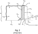
- FIG. 2 is a cross-sectional view of corner region R of seal housing 16pa.
- Seal housing 16pa is a prior art design for seal housing 16 featuring a simple chamfered corner.
- Seal housing 16pa has housing axially facing surface 26pa and housing inner annular surface 28pa, which meet at housing ID corner 30pa, generally as described above.
- Seal housing 16pa is formed of coating 32pa bonded to substrate 34pa.
- Substrate 34pa has axially facing substrate surface 36pa, which transitions to housing inner annular surface 28pa via chamfer 38pa. Housing inner annular surface 28pa is uncoated.
- Coating 32pa defines the entirety of housing axially facing surface 26pa, as well as coating ID surface 40pa near housing ID corner 30pa. In some cases, coating ID surface 40pa can deviate from housing inner annular surface 28pa, causing a shift in the location of housing ID corner 30pa.
- Coating 32pa is bonded to substrate 34pa via spray deposition with spray apparatus SA at spray orientation S.
- Spray orientation S is obtusely angled at spray angle ⁇ S with respect to housing axially facing surface 26pa.
- Spray orientation S is directed partially radially inward, to avoid depositing coating material on housing inner annular surface 28pa.
- coating 32pa is initially deposited to an excessive thickness out to initial axial coating surface 42pa, and excess coating material deposited is subsequently machined away to produce a finished, smooth surface grind plane 44.
- Coating 32pa bonds readily to substrate 34pa along substrate axially facing surface 36pa, but the shallow angle of attack of spray orientation S with respect to chamfer 38pa can cause coating material be partially deflected at chamfer 38pa, resulting in departure of coating ID surface 40pa from the straight cross-section of housing inner annular surface 28pa.
- coating ID surface 40pa can deviate from a desired annular profile, such that the actual location of housing ID corner 30pa is offset radially outward from an ideal sharp corner location (labeled 30 T ) by deviation distance d dev .
- Target corner 30 T is situated at the intersection of annular surface 28pa and grind plane 40.
- Deviation distance d dev is a cross-sectional distance between target corner 30 T and the actual location of corner 30 at the intersection of coating ID surface 40 and housing axially facing surface 26pa.
- deviation distance d dev can offset housing ID corner 30pa enough to elevate housing ID corner 30pa radially outward of step corner 24, such that radial offset distance d offset is negative (see FIG. 1 ).
- the acylindrical irregularity of coating ID surface 40pa can cause imbalances in seal assembly 10 and part failures in seal segment 14, in particular.
- corner structures for seal housings include unchamfered corners at the intersection of annular and axially-facing housing surfaces. These unchamfered designs can suffer from chipping or delamination of coating from axially-facing surfaces. Chamfer 38pa substantially avoids this chipping and delamination. As discussed above, however, chamfer 38pa can produce damaging irregularities in the location of housing ID corner 30 relative to step corner 24.
- FIG. 3 is a cross-sectional view of corner region R of seal housing 16 of FIG. 1 .
- Seal housing 16 generally parallels prior art seal housing 16pa, as described above, but has additional corner features to prevent coating ID surface drift that could cause changes in the location of housing ID corner 30.
- Seal housing 16 has housing axially facing surface 26 and housing inner annular surface 28, which meet at housing ID corner 30.
- Seal housing 16 includes coating 32 bonded to substrate 34 where seal housing 16 abuts seal segment 14 (see FIG. 1 ).
- Substrate 34 has substrate axially facing surface 36 parallel to housing axially facing surface 26, generally as described above with respect to prior art substrate 34pa, except that substrate axially facing surface 36 ends further from housing ID corner 30.
- coating 32 forms axially facing surface 26 and coating ID surface 40.
- substrate 34 includes notch 46, an annular notch that can, for example, have a rectangular cross-section as illustrated in FIG. 3 .
- Notch 46 is defined by axially facing notch surface 48 and annular notch surface 50.
- axially facing notch surface 48 is perpendicular to axis A and parallel to housing axially facing surface 26, and annular notch surface 50 is perpendicular to axially facing notch surface 48 and consequently parallel to housing inner annular surface 28 in substrate 34.
- notch 46 has a radial width of d r and an axial width of d a .
- Notch 46 provides a bonding surface for coating 32, thereby avoiding irregular coating build-up along coating ID surface 40, such that housing ID corner 30 aligns with housing inner annular surface 28.
- chamfer 38 defines a frustoconical surface connecting substrate axially facing surface 36 and annular notch surface 50.
- Chamfer 38 thereby provides the aforementioned benefits of reducing chipping and delamination, while notch 46 prevents coating deflection and resulting acylindrical coating shape at housing ID corner 30.
- Chamfer 38 is defined by chamfer angles ⁇ 1 and ⁇ 2 . In one embodiment, chamfer angles ⁇ 1 and ⁇ 2 are both 45°.
- coating material is deposited on substrate 34 via spray apparatus SA (shown only schematically) aimed obliquely radially inward with respect to axis A, and obtusely with respect to housing axially facing surface 26, at orientation S described by spray angle ⁇ s .
- Coating material can be deposited to initial axially facing coating surface 42, and housing axially facing surface 26 formed by machining away excess material to grind plane 44.
- the post-machining thickness of coating 32 along substrate axially facing surface 36 is coating thickness t.
- radial notch width d r and axial notch width d a are both greater than or equal to coating thickness t to encourage coating material bonding in notch 46.
- Spray angle ⁇ s is selected to avoid depositing coating material along inner annular surface 28, while providing a shallow angle of attack to minimize spray deflection and encourage coating bonding to substrate 34.
- Spray angle ⁇ s can, for example, be an obtuse angle greater than or equal to 60°. In general, spray angle ⁇ s is greater than chamfer angle ⁇ 2 , but less than 90°. Where chamfer angle ⁇ 1 is 45°, chamfer 38 and spray orientation S are separated by 45° or less, so as to avoid depositing spray material on housing inner annular surface 28.
- corner substrate feature situated at an ID location
- this corner feature can analogously be applied to OD annular corners and to non-cylindrical structures, as well.
- the corner feature described herein encourages coating bonding to produce a uniform inner annular surface with housing ID corner 30 aligned with housing inner annular surface 28. Notch 48 and chamfer 38 accordingly reduce the risk of part failures due to misalignment of housing ID corner 30 relative to step corner 24.
- a seal housing disposed to support an axially facing seal segment, the seal housing comprising: a substrate having an inner annular surface, an axially facing substrate surface, and a corner feature at an intersection of the inner annular surface and the axially facing substrate surface, the corner feature including an annular notch in the inner annular surface, and a chamfer extending from the annular notch to the axially facing substrate surface; and a coating formed on the axially facing substrate surface and into the corner feature of the substrate, and having a coating surface, parallel to the axially facing substrate surface, that terminates at the inner annular surface and abuts the seal segment.
- seal housing of the preceding paragraph can optionally include, additionally and/or alternatively, any one or more of the following features, configurations and/or additional components:
- a further embodiment of any of the foregoing seal housings wherein the coating surface is separated from the axially facing substrate surface by a coating thickness, and wherein the axially facing notch surface has a radial extent greater than or equal to the coating thickness.
- a further embodiment of any of the foregoing seal housings wherein the coating surface is separated from the axially facing substrate surface by a coating thickness, and wherein the annular notch surface has an axial extent greater than or equal to the coating thickness.
- a method of forming an edge of an annular workpiece comprising: fabricating a substrate having an annular surface, an axially facing substrate surface, and a corner feature at the intersection of the annular surface and the axially facing substrate surface, the corner feature including an annular notch in the annular surface, and a chamfer extending from the annular notch to the axially facing substrate surface; depositing coating material into the corner feature and on the axially facing substrate surface, axially out to at least a target plane parallel to the axially facing substrate surface, via spray deposition at a spray orientation obtuse to the axially facing substrate surface and at least an axial surface of the annular notch; and removing excess coating material beyond the target plane, such that the coating material has a uniform first axial thickness along the axially facing substrate surface, and greater thickness within the corner feature.
- the method of the preceding paragraph can optionally include, additionally and/or alternatively, any one or more of the following features, configurations and/or additional components:
- a seal assembly comprising: a rotating shaft; a seal segment situated on and reciprocatable with the rotating shaft, the seal segment having an axially facing seal surface terminating at a first inner radial extent; a seal housing situated adjacent the seal segment and around the rotating shaft, the seal housing comprising: a substrate terminating at a second inner radial extent inboard of the first inner radial extent, the substrate having an annular notch at a corner adjacent the seal segment, the annular notch extending radially outward from the second inner radial extent, inboard and axially forward of a corner chamfer; and a coated surface deposited atop the substrate, covering the annular notch and the corner chamfer, abutting the axially facing seal surface and terminating at the second inner radial extent.
- seal assembly of the preceding paragraph can optionally include, additionally and/or alternatively, any one or more of the following features, configurations and/or additional components:
- seal segment is formed at least partially of carbon.
- the substrate comprises: a primary coated axial surface parallel to the axial seal face; an inner annular surface situated at the second inner radial extent; an axially facing notch surface parallel to and inboard of the coated axial surface; an annular notch surface situated parallel to and outboard of the inner annular surface, and extending axially from the axially facing notch surface to the corner chamfer, such that the axially facing notch surface and the annular notch surface together define the rectangular cross-section of the notch.
- seal segment is permitted to displace radially up to a deflection distance with respect to the seal housing.
- any relative terms or terms of degree used herein such as “substantially”, “essentially”, “generally”, “approximately” and the like, should be interpreted in accordance with and subject to any applicable definitions or limits expressly stated herein. In all instances, any relative terms or terms of degree used herein should be interpreted to broadly encompass any relevant disclosed embodiments as well as such ranges or variations as would be understood by a person of ordinary skill in the art in view of the entirety of the present disclosure, such as to encompass ordinary manufacturing tolerance variations, incidental alignment variations, alignment or shape variations induced by thermal, rotational or vibrational operational conditions, and the like.
Landscapes
- Engineering & Computer Science (AREA)
- General Engineering & Computer Science (AREA)
- Mechanical Engineering (AREA)
- Chemical & Material Sciences (AREA)
- Physics & Mathematics (AREA)
- Plasma & Fusion (AREA)
- Chemical Kinetics & Catalysis (AREA)
- Materials Engineering (AREA)
- Metallurgy (AREA)
- Organic Chemistry (AREA)
- Sealing Using Fluids, Sealing Without Contact, And Removal Of Oil (AREA)
- Turbine Rotor Nozzle Sealing (AREA)
Abstract
Description
- The present invention relates generally to bearing assemblies, and more particularly to a coated seal housing structure suitable for use in a gas turbine seal assembly.
- Coated structures such as seal housings can have strict tolerances requiring even, sharply-angled corners. Coatings are applied to substrate surfaces, and delamination and irregularity of coating deposition can create imperfections in corners of the resulting coated structure. In seal assemblies, irregularities in corner location near intersections of facing parts can increase wear and/or introduce part failures. Some coated seal housings include chamfers at ID annular corners of substrates to reduce chipping and delamination. Chamfered substrate corners can produce irregularities in coated ID corner location that are harmful to adjacent components.
- In one aspect, the present invention is directed toward a seal housing disposed to support an axially facing seal segment. The seal housing comprises a substrate and a coating. The substrate has an inner annular surface, an axially facing substrate surface, and a corner feature at an intersection of the inner annular surface and the axially facing substrate surface. The corner feature includes an annular notch in the inner annular surface, and a chamfer extending from the annular notch to the axially facing substrate surface. The coating is formed on the axially facing substrate surface and into the corner feature of the substrate, and has a coating surface, parallel to the axially facing substrate surface, that terminates at the inner annular surface and abuts the seal segment.
- In another aspect, the present invention is directed toward a method of forming an edge of an annular workpiece by fabricating a substrate, depositing coating material onto the substrate, and removing excess coating material beyond a target plane. The substrate is formed with an annular surface, an axially facing substrate surface, and a corner feature at the intersection of the annular surface and the axially facing substrate surface. The corner feature includes an annular notch in the annular surface, and a chamfer extending from the annular notch to the axially facing substrate surface. Coating material is spray deposited into the corner feature and on the axially facing substrate surface, axially out to at least a target plane parallel to the axially facing substrate surface. The coating is sprayed at a spray orientation obtuse to the axially facing substrate surface and at least an axial surface of the annular notch. Removing excess material beyond the target plane provides the coating with a uniform first axial thickness along the axially facing substrate surface, and a greater thickness within the corner feature.
- In yet another aspect, the present invention is directed toward a seal assembly comprising a rotating shaft, a seal segment, and a seal housing. The seal segment is situated on and reciprocatable with the rotating shaft, and has an axially facing seal surface terminating at a first inner radial extent. The seal housing is situated adjacent the seal segment and around the rotating shaft, and comprises a substrate underlying a coated surface. The substrate terminates at a second inner radial extent inboard of the first inner radial extent, and has an annular notch at a corner adjacent the seal segment. The annular notch extendes radially outward from the second inner radial extent, inboard and axially forward of a corner chamfer. The coated surface is deposited atop the substrate, covering the annular notch and the corner chamfer, abutting the axially facing seal surface, and terminating at the second inner radial extent.
- The present summary is provided only by way of example, and not limitation. Other aspects of the present disclosure will be appreciated in view of the entirety of the present disclosure, including the entire text, claims, and accompanying figures.
-
-
FIG. 1 is cross-sectional view of a seal assembly including a seal housing abutting a seal segment. -
FIG. 2 is a schematic cross-sectional view a prior art design for an edge region of the seal housing ofFIG. 1 . -
FIG. 3 is a schematic cross-sectional view of a new design of an edge region of the seal housing ofFIG. 1 . - While the above-identified figures set forth one or more embodiments of the present disclosure, other embodiments are also contemplated, as noted in the discussion. In all cases, this disclosure presents the invention by way of representation and not limitation. It should be understood that numerous other modifications and embodiments can be devised by those skilled in the art, which fall within the scope of the principles of the invention. The figures may not be drawn to scale, and applications and embodiments of the present invention may include features and components not specifically shown in the drawings.
- The present invention provides a substrate structure for a coated annular corner. This substrate structure includes a corner feature with an annular notch situated between a corner chamfer and an uncoated surface. This notch encourages bonding of coating material at corner of the substrate, reducing circumferential variation in post-coat corner location and accordingly reducing the risk of part failures due to malpositioning.
-
FIG. 1 is a cross-sectional view ofseal assembly 10, which includesshaft 12,seal segment 14, andseal housing 16.Shaft 12 is a rotating element extending along axisA. Seal segment 14 includesspring 18, seal segment axially facingsurface 20,segment step 22, andstep corner 24.Seal housing 16 includes housing axially facingsurface 26 and housing innerannular surface 28, which meet at housing inner diameter (ID)corner 30 in region R. -
Seal segment 14 is a sealing element of a seal assembly, e.g. a shaft seal assembly of a gas turbine engine.Seal segment 14 is retained radially byspring 18, and ridesshaft 12, reciprocating with runout ofshaft 12.Seal segment 14 can, for example, be formed partially or entirely of carbon.Seal segment 14abuts seal housing 16 axially at seal segment axially facingsurface 20. In the illustrated embodiment, seal segment axially facingsurface 20 transitions at an ID location intosegment step 22 viastep corner 24, such thatstep corner 24 defines the ID extent of seal segment axially facingsurface 20 at its contact withseal housing 16. Seal segment is separated radially fromseal housing 16, and onlycontacts seal housing 16 via seal segment axially facingsurface 20. -
Seal housing 16 is a stationary retaining structure thatpositions seal segment 14 from an axially forward position.Seal housing 16 does not rotate withshaft 12 and or reciprocate withseal segment 14.Seal housing 16 can, for example, be formed of a metal substrate coated with a high velocity oxygen fueled (HVOF) coating. The substrate ofseal housing 16 can for example be formed of a metal such as aluminum, or of an alloy such as steel. Seal housing 16 contacts seal segment axially facingsurface 20 with housing axially facingsurface 26. Seal segment axially facingsurface 20 and housing axially facingsurface 26 are parallel surfaces, and can in one embodiment be strictly radially extending surfaces normal to axis A ofshaft 12. Housing axially facingsurface 26 extends radially to a minimum radial position defined by housing innerannular surface 28. Housing innerannular surface 28 surrounds but does not contactshaft 12. Housing axially facingsurface 26 and housing innerannular surface 28 meet athousing ID corner 30, within region R ofseal housing 16.Housing ID corner 30 is discussed in greater detail below with respect toFIG. 3 , and is contrasted with prior art structures with respect toFIG. 2 . - Inner
annular surface 28 ofseal housing 16 is separated fromshaft 12 by shaft separation distance dshaft.Segment step 22 of seal segment axially facingsurface 20 is situated a step distance dstep fromshaft 12.Step corner 24 is consequently situated a radial offset distance doffset fromhousing ID corner 30, wherein doffset = dstep - dshaft. Over the course of normal operation ofseal assembly 10,shaft 12 can deflect, vibrate, rotate, or translate with respect toseal housing 16, causing shaft separation distance dshaft (and consequently doffset) to vary slightly.Housing ID corner 30 is situated radially inboard ofstep corner 24, such that offset distance doffset represents a distance radially inward fromstep corner 24 tohousing ID corner 30. Increased wear, imbalances, and part failures can occur ifstep corner 24 is situated radially inboard ofhousing ID corner 30. In some cases, for example, malpositioning ofhousing ID corner 30 relative tostep corner 24 could cause the seal segment axially facingsurface 20 to form uneven wear and damage theseal segment 14 ifhousing ID corner 30 were to fall radially outward ofstep corner 24. These failure conditions are avoided by fabricatinghousing ID corner 30 to strict specifications. -
FIG. 2 is a cross-sectional view of corner region R of seal housing 16pa. Seal housing 16pa is a prior art design forseal housing 16 featuring a simple chamfered corner. Seal housing 16pa has housing axially facing surface 26pa and housing inner annular surface 28pa, which meet at housing ID corner 30pa, generally as described above. Seal housing 16pa is formed of coating 32pa bonded to substrate 34pa. Substrate 34pa has axially facing substrate surface 36pa, which transitions to housing inner annular surface 28pa via chamfer 38pa. Housing inner annular surface 28pa is uncoated. Coating 32pa defines the entirety of housing axially facing surface 26pa, as well as coating ID surface 40pa near housing ID corner 30pa. In some cases, coating ID surface 40pa can deviate from housing inner annular surface 28pa, causing a shift in the location of housing ID corner 30pa. - Coating 32pa is bonded to substrate 34pa via spray deposition with spray apparatus SA at spray orientation S. Spray orientation S is obtusely angled at spray angle θS with respect to housing axially facing surface 26pa. Spray orientation S is directed partially radially inward, to avoid depositing coating material on housing inner annular surface 28pa. In at least some embodiments, coating 32pa is initially deposited to an excessive thickness out to initial axial coating surface 42pa, and excess coating material deposited is subsequently machined away to produce a finished, smooth
surface grind plane 44. - Coating 32pa bonds readily to substrate 34pa along substrate axially facing surface 36pa, but the shallow angle of attack of spray orientation S with respect to chamfer 38pa can cause coating material be partially deflected at chamfer 38pa, resulting in departure of coating ID surface 40pa from the straight cross-section of housing inner annular surface 28pa. In particular, coating ID surface 40pa can deviate from a desired annular profile, such that the actual location of housing ID corner 30pa is offset radially outward from an ideal sharp corner location (labeled 30T) by deviation distance ddev.
Target corner 30T is situated at the intersection of annular surface 28pa and grindplane 40. Deviation distance ddev is a cross-sectional distance betweentarget corner 30T and the actual location ofcorner 30 at the intersection ofcoating ID surface 40 and housing axially facing surface 26pa. In some cases, deviation distance ddev can offset housing ID corner 30pa enough to elevate housing ID corner 30pa radially outward ofstep corner 24, such that radial offset distance doffset is negative (seeFIG. 1 ). In such cases, the acylindrical irregularity of coating ID surface 40pa can cause imbalances inseal assembly 10 and part failures inseal segment 14, in particular. - Some alternative prior art designs of corner structures for seal housings include unchamfered corners at the intersection of annular and axially-facing housing surfaces. These unchamfered designs can suffer from chipping or delamination of coating from axially-facing surfaces. Chamfer 38pa substantially avoids this chipping and delamination. As discussed above, however, chamfer 38pa can produce damaging irregularities in the location of
housing ID corner 30 relative to stepcorner 24. -
FIG. 3 is a cross-sectional view of corner region R ofseal housing 16 ofFIG. 1 .Seal housing 16 generally parallels prior art seal housing 16pa, as described above, but has additional corner features to prevent coating ID surface drift that could cause changes in the location ofhousing ID corner 30.Seal housing 16 has housing axially facingsurface 26 and housing innerannular surface 28, which meet athousing ID corner 30.Seal housing 16 includescoating 32 bonded tosubstrate 34 whereseal housing 16 abuts seal segment 14 (seeFIG. 1 ).Substrate 34 has substrate axially facingsurface 36 parallel to housing axially facingsurface 26, generally as described above with respect to prior art substrate 34pa, except that substrate axially facingsurface 36 ends further fromhousing ID corner 30. - As described similarly with respect to prior art seal housing 16pa of
FIG. 2 , coating 32 forms axially facingsurface 26 andcoating ID surface 40. Unlike prior art substrate 34pa,substrate 34 includesnotch 46, an annular notch that can, for example, have a rectangular cross-section as illustrated inFIG. 3 .Notch 46 is defined by axially facingnotch surface 48 andannular notch surface 50. In at least some embodiments axially facingnotch surface 48 is perpendicular to axis A and parallel to housing axially facingsurface 26, andannular notch surface 50 is perpendicular to axially facingnotch surface 48 and consequently parallel to housing innerannular surface 28 insubstrate 34. In the illustratedembodiment notch 46 has a radial width of dr and an axial width of da.Notch 46 provides a bonding surface for coating 32, thereby avoiding irregular coating build-up alongcoating ID surface 40, such thathousing ID corner 30 aligns with housing innerannular surface 28. Rather than forming a transition between substrate axially facingsurface 36 and housing inner annular surface 28 (seeFIG. 2 ),chamfer 38 defines a frustoconical surface connecting substrate axially facingsurface 36 andannular notch surface 50.Chamfer 38 thereby provides the aforementioned benefits of reducing chipping and delamination, whilenotch 46 prevents coating deflection and resulting acylindrical coating shape athousing ID corner 30.Chamfer 38 is defined by chamfer angles ϕ1 and ϕ2. In one embodiment, chamfer angles ϕ1 and ϕ2 are both 45°. - As discussed above with respect to
FIG. 2 , coating material is deposited onsubstrate 34 via spray apparatus SA (shown only schematically) aimed obliquely radially inward with respect to axis A, and obtusely with respect to housing axially facingsurface 26, at orientation S described by spray angle θs. Coating material can be deposited to initial axially facingcoating surface 42, and housing axially facingsurface 26 formed by machining away excess material to grindplane 44. In the illustrated embodiment, the post-machining thickness ofcoating 32 along substrate axially facingsurface 36 is coating thickness t. In some embodiments, radial notch width dr and axial notch width da are both greater than or equal to coating thickness t to encourage coating material bonding innotch 46. - Spray angle θs is selected to avoid depositing coating material along inner
annular surface 28, while providing a shallow angle of attack to minimize spray deflection and encourage coating bonding tosubstrate 34. Spray angle θs can, for example, be an obtuse angle greater than or equal to 60°. In general, spray angle θs is greater than chamfer angle ϕ2, but less than 90°. Where chamfer angle ϕ1 is 45°,chamfer 38 and spray orientation S are separated by 45° or less, so as to avoid depositing spray material on housing innerannular surface 28. - Although the present description focuses on a corner substrate feature situated at an ID location, a person skilled in the art will recognize that this corner feature can analogously be applied to OD annular corners and to non-cylindrical structures, as well.
- The corner feature described herein, with
notch 46 andchamfer 38, encourages coating bonding to produce a uniform inner annular surface withhousing ID corner 30 aligned with housing innerannular surface 28.Notch 48 andchamfer 38 accordingly reduce the risk of part failures due to misalignment ofhousing ID corner 30 relative to stepcorner 24. - The following are non-exclusive descriptions of possible embodiments of the present invention.
- A seal housing disposed to support an axially facing seal segment, the seal housing comprising: a substrate having an inner annular surface, an axially facing substrate surface, and a corner feature at an intersection of the inner annular surface and the axially facing substrate surface, the corner feature including an annular notch in the inner annular surface, and a chamfer extending from the annular notch to the axially facing substrate surface; and a coating formed on the axially facing substrate surface and into the corner feature of the substrate, and having a coating surface, parallel to the axially facing substrate surface, that terminates at the inner annular surface and abuts the seal segment.
- The seal housing of the preceding paragraph can optionally include, additionally and/or alternatively, any one or more of the following features, configurations and/or additional components:
- A further embodiment of the foregoing seal housing, wherein the annular notch comprises: an axially facing notch surface extending radially outward from the inner annular surface; and an annular notch surface extending axially towards the chamfer from the axially facing notch surface.
- A further embodiment of any of the foregoing seal housings, wherein the chamfer is a frustoconical surface extending from the annular notch surface to the axially facing substrate surface, and angled radially outward and axially away from the axially facing notch surface.
- A further embodiment of any of the foregoing seal housings, wherein the frustoconical surface is angled at 45° with respect to the annular notch surface and the axially facing substrate surface.
- A further embodiment of any of the foregoing seal housings, wherein the coating surface is separated from the axially facing substrate surface by a coating thickness, and wherein the axially facing notch surface has a radial extent greater than or equal to the coating thickness.
- A further embodiment of any of the foregoing seal housings, wherein the coating surface is separated from the axially facing substrate surface by a coating thickness, and wherein the annular notch surface has an axial extent greater than or equal to the coating thickness.
- A method of forming an edge of an annular workpiece, the method comprising: fabricating a substrate having an annular surface, an axially facing substrate surface, and a corner feature at the intersection of the annular surface and the axially facing substrate surface, the corner feature including an annular notch in the annular surface, and a chamfer extending from the annular notch to the axially facing substrate surface; depositing coating material into the corner feature and on the axially facing substrate surface, axially out to at least a target plane parallel to the axially facing substrate surface, via spray deposition at a spray orientation obtuse to the axially facing substrate surface and at least an axial surface of the annular notch; and removing excess coating material beyond the target plane, such that the coating material has a uniform first axial thickness along the axially facing substrate surface, and greater thickness within the corner feature.
- The method of the preceding paragraph can optionally include, additionally and/or alternatively, any one or more of the following features, configurations and/or additional components:
- A further embodiment of the foregoing method, wherein the annular notch comprises: an axially facing notch surface extending at a right angle from the annular surface; and an annular notch surface extending at a right angle from the axially facing notch surface to the chamfer.
- A further embodiment of any of the foregoing methods, wherein the chamfer extends frustoconically from the annular notch surface to the axially facing substrate surface.
- A further embodiment of any of the foregoing methods, wherein the spray orientation is angled at more than 60° with respect to the axially facing substrate surface.
- A further embodiment of any of the foregoing methods, wherein the chamfer forms a 45° angle with respect to the annular notch surface and the axially facing substrate surface.
- A further embodiment of any of the foregoing methods, wherein the spray orientation is angled at less than 45° with respect to the chamfer.
- A seal assembly comprising: a rotating shaft; a seal segment situated on and reciprocatable with the rotating shaft, the seal segment having an axially facing seal surface terminating at a first inner radial extent; a seal housing situated adjacent the seal segment and around the rotating shaft, the seal housing comprising: a substrate terminating at a second inner radial extent inboard of the first inner radial extent, the substrate having an annular notch at a corner adjacent the seal segment, the annular notch extending radially outward from the second inner radial extent, inboard and axially forward of a corner chamfer; and a coated surface deposited atop the substrate, covering the annular notch and the corner chamfer, abutting the axially facing seal surface and terminating at the second inner radial extent.
- The seal assembly of the preceding paragraph can optionally include, additionally and/or alternatively, any one or more of the following features, configurations and/or additional components:
- A further embodiment of the foregoing seal assembly, wherein the seal segment is a gas turbine engine bearing seal.
- A further embodiment of any of the foregoing seal assemblies, wherein coating is a high velocity oxygen fuel coating.
- A further embodiment of any of the foregoing seal assemblies, wherein the seal segment is formed at least partially of carbon.
- A further embodiment of any of the foregoing seal assemblies, wherein the annular notch has a rectangular cross-section.
- A further embodiment of any of the foregoing seal assemblies, wherein the substrate comprises: a primary coated axial surface parallel to the axial seal face; an inner annular surface situated at the second inner radial extent; an axially facing notch surface parallel to and inboard of the coated axial surface; an annular notch surface situated parallel to and outboard of the inner annular surface, and extending axially from the axially facing notch surface to the corner chamfer, such that the axially facing notch surface and the annular notch surface together define the rectangular cross-section of the notch.
- A further embodiment of any of the foregoing seal assemblies, wherein the seal segment is permitted to displace radially up to a deflection distance with respect to the seal housing.
- A further embodiment of any of the foregoing seal assemblies, wherein the deflection distance is less than a radial separation between the first inner radial extent and the second inner radial extent.
- Any relative terms or terms of degree used herein, such as "substantially", "essentially", "generally", "approximately" and the like, should be interpreted in accordance with and subject to any applicable definitions or limits expressly stated herein. In all instances, any relative terms or terms of degree used herein should be interpreted to broadly encompass any relevant disclosed embodiments as well as such ranges or variations as would be understood by a person of ordinary skill in the art in view of the entirety of the present disclosure, such as to encompass ordinary manufacturing tolerance variations, incidental alignment variations, alignment or shape variations induced by thermal, rotational or vibrational operational conditions, and the like.
- While the invention has been described with reference to an exemplary embodiment(s), it will be understood by those skilled in the art that various changes may be made and equivalents may be substituted for elements thereof without departing from the scope of the invention. In addition, many modifications may be made to adapt a particular situation or material to the teachings of the invention without departing from the essential scope thereof. Therefore, it is intended that the invention not be limited to the particular embodiment(s) disclosed, but that the invention will include all embodiments falling within the scope of the appended claims.
Claims (15)
- A seal housing (16) disposed to support an axially facing seal segment (14), the seal housing (16) comprising:a substrate (34) having an inner annular surface (28), an axially facing substrate surface (36), and a corner feature at an intersection of the inner annular surface (28) and the axially facing substrate surface (36), the corner feature including an annular notch (46) in the inner annular surface (28), and a chamfer (38) extending from the annular notch (46) to the axially facing substrate surface (36); anda coating (32) formed on the axially facing substrate surface (36) and into the corner feature of the substrate (34), and having a coating surface (26), parallel to the axially facing substrate surface (36), that terminates at the inner annular surface (28) and abuts the seal segment (14).
- The seal housing of claim 1, wherein the annular notch (46) comprises:an axially facing notch surface (48) extending radially outward from the inner annular surface (28); andan annular notch surface (50) extending axially towards the chamfer (38) from the axially facing notch surface (48).
- The seal housing of claim 2, wherein the chamfer (38) is a frustoconical surface extending from the annular notch surface (50) to the axially facing substrate surface (36), and angled radially outward and axially away from the axially facing notch surface (48) wherein, optionally, the frustoconical surface (38) is angled at 45° with respect to the annular notch surface (50) and the axially facing substrate surface (36).
- The seal housing of claim 2 or 3, wherein the coating surface (26) is separated from the axially facing substrate surface (36) by a coating thickness (t), and wherein the axially facing notch surface (48) has a radial extent (dr) greater than or equal to the coating thickness (t).
- The seal housing of any of claims 2 to 4, wherein the coating surface (26) is separated from the axially facing substrate surface (36) by a or the coating thickness (t), and wherein the annular notch surface (50) has an axial extent (da) greater than or equal to the coating thickness (t).
- A method of forming an edge of an annular workpiece, the method comprising:fabricating a substrate (34) having an annular surface (28), an axially facing substrate surface (36), and a corner feature at the intersection of the annular surface (28) and the axially facing substrate surface (36), the corner feature including an annular notch (46) in the annular surface (28), and a chamfer (38) extending from the annular notch (46) to the axially facing substrate surface (36);depositing coating material into the corner feature and on the axially facing substrate surface (36), axially out to at least a target plane (44) parallel to the axially facing substrate surface (26), via spray deposition at a spray orientation (S) obtuse to the axially facing substrate surface (36) and at least an axial surface (48) of the annular notch (46); andremoving excess coating material beyond the target plane (44), such that the coating material has a uniform first axial thickness (t) along the axially facing substrate surface (36), and greater thickness within the corner feature.
- The method of claim 6, wherein the annular notch (46) comprises:an axially facing notch surface (48) extending at a right angle from the annular surface (28); andan annular notch surface (50) extending at a right angle from the axially facing notch surface (48) to the chamfer (38).wherein, optionally, the chamfer (38) extends frustoconically from the annular notch surface (50) to the axially facing substrate surface (36).
- The method of claim 6 or 7, wherein the spray orientation (S) is angled at more than 60° with respect to the axially facing substrate surface (36).
- The method of any of claims 6 to 8, wherein the chamfer (38) forms a 45° angle with respect to the annular notch surface (50) and the axially facing substrate surface (26), and wherein, optionally, the spray orientation (S) is angled at less than 45° with respect to the chamfer (38).
- A seal assembly (10) comprising:a rotating shaft (12);a seal segment (14) situated on and reciprocatable with the rotating shaft (12), the seal segment (14) having an axially facing seal surface (20) terminating at a first inner radial extent (dstep);a seal housing (16) situated adjacent the seal segment (14) and around the rotating shaft (12), the seal housing (16) comprising:a substrate (34) terminating at a second inner radial extent (dshaft) inboard of the first inner radial extent (dstep), the substrate (34) having an annular notch (46) at a corner adjacent the seal segment (14), the annular notch (46) extending radially outward from the second inner radial extent (dshaft), inboard and axially forward of a corner chamfer (38); anda coated surface (32) deposited atop the substrate (34), covering the annular notch (46) and the corner chamfer (38), abutting the axially facing seal surface (20) and terminating at the second inner radial extent (dshaft), wherein the seal segment (14) is a gas turbine engine bearing seal.
- The seal assembly of claim 10, wherein the coated surface (32) comprises a high velocity oxygen fuel coating (32).
- The seal assembly of claim 10 or 11, wherein the seal segment (14) is formed at least partially of carbon.
- The seal assembly of any of claims 10 to 12, wherein the annular notch (46) has a rectangular cross-section.
- The seal assembly of claim 13, wherein the substrate (34) comprises:a primary coated axial surface (26) parallel to the axial seal face (20);an inner annular surface (28) situated at the second inner radial extent (dshaft);an axially facing notch surface (48) parallel to and inboard of the coated axial surface (26);an annular notch surface (50) situated parallel to and outboard of the inner annular surface (28), and extending axially from the axially facing notch surface (48) to the corner chamfer (38), such that the axially facing notch surface (48) and the annular notch surface (50) together define the rectangular cross-section of the notch.
- The seal assembly of any of claims 10 to 14, wherein the seal segment (14) is permitted to displace radially up to a deflection distance with respect to the seal housing (16), wherein, optionally, the deflection distance is less than a radial separation (doffset) between the first inner radial extent (dstep) and the second inner radial extent (dshaft).
Applications Claiming Priority (1)
| Application Number | Priority Date | Filing Date | Title |
|---|---|---|---|
| US15/208,035 US9995397B2 (en) | 2016-07-12 | 2016-07-12 | Coated seal housing |
Publications (2)
| Publication Number | Publication Date |
|---|---|
| EP3269839A1 true EP3269839A1 (en) | 2018-01-17 |
| EP3269839B1 EP3269839B1 (en) | 2019-11-27 |
Family
ID=59409152
Family Applications (1)
| Application Number | Title | Priority Date | Filing Date |
|---|---|---|---|
| EP17180315.8A Active EP3269839B1 (en) | 2016-07-12 | 2017-07-07 | Coated seal housing |
Country Status (2)
| Country | Link |
|---|---|
| US (1) | US9995397B2 (en) |
| EP (1) | EP3269839B1 (en) |
Families Citing this family (2)
| Publication number | Priority date | Publication date | Assignee | Title |
|---|---|---|---|---|
| EP4466476A1 (en) | 2022-01-21 | 2024-11-27 | RTX Corporation | Carbon face seal |
| US12060797B2 (en) | 2022-01-21 | 2024-08-13 | Rtx Corporation | Carbon face seal |
Citations (3)
| Publication number | Priority date | Publication date | Assignee | Title |
|---|---|---|---|---|
| US20040226547A1 (en) * | 2003-02-07 | 2004-11-18 | Johann Holzleitner | Plasma coating for cylinder liner and method for applying the same |
| US20100164179A1 (en) * | 2008-01-25 | 2010-07-01 | Yuichi Hirakawa | Seal structure |
| EP3037570A1 (en) * | 2014-12-15 | 2016-06-29 | United Technologies Corporation | Seal coating |
Family Cites Families (34)
| Publication number | Priority date | Publication date | Assignee | Title |
|---|---|---|---|---|
| US1181618A (en) | 1915-09-17 | 1916-05-02 | Alba J Smith | Piston-ring. |
| US1635407A (en) | 1922-02-27 | 1927-07-12 | Grover Ray | Piston ring |
| US1532938A (en) | 1923-02-10 | 1925-04-07 | Dock J Peeler | Piston ring |
| US2068042A (en) | 1933-10-30 | 1937-01-19 | Perfect Circle Co | Piston and piston ring |
| US2386873A (en) | 1943-08-16 | 1945-10-16 | Mercier Jean | Duplex elastic seal |
| US2917329A (en) | 1955-05-13 | 1959-12-15 | City Nat Bank And Trust Compan | Rotary seal |
| US3655208A (en) | 1970-04-13 | 1972-04-11 | Mc Donnell Douglas Corp | Split piston ring and method of manufacture |
| JPS5412022A (en) * | 1977-06-25 | 1979-01-29 | Goetzewerke | Machine portion material exposed to wear that has coating layer on sliding surface in shape that riser portion is mounted to one side or both sides |
| US4189161A (en) | 1978-08-28 | 1980-02-19 | Muskegon Piston Ring Company | Bi-directional ring gap seal |
| US4256318A (en) | 1980-04-28 | 1981-03-17 | Sealed Power Corporation | Piston ring |
| GB2134604B (en) | 1983-01-28 | 1986-03-12 | Cross Mfg Co | Rotatable shaft seals |
| JPS59126158U (en) | 1983-02-12 | 1984-08-24 | 株式会社リケン | Piston for reciprocating internal combustion engine |
| US4844487A (en) | 1988-11-04 | 1989-07-04 | Kaydon Corporation | Lock-step duo step split sealing ring |
| US5056935A (en) | 1990-11-05 | 1991-10-15 | General Electric Company | Oil film damper seal ring |
| US5178400A (en) | 1991-01-14 | 1993-01-12 | General Electric Company | Squeeze film damper seal |
| JPH04362370A (en) | 1991-06-04 | 1992-12-15 | Riken Corp | Compression ring for internal combustion engine |
| GB2264541A (en) | 1992-02-29 | 1993-09-01 | Rolls Royce Plc | Improved sealing ring for gas turbine engines |
| US5292138A (en) | 1992-09-21 | 1994-03-08 | General Elecric Company | Rotor to rotor split ring seal |
| JP3324887B2 (en) | 1994-11-08 | 2002-09-17 | 本田技研工業株式会社 | Hydraulic sealing device |
| WO1996021116A1 (en) | 1995-01-04 | 1996-07-11 | Polypenco Kunststofftechnik Gmbh | Sealing ring |
| US5934680A (en) | 1995-05-31 | 1999-08-10 | Ntn Corporation | Split resin seal ring with chamfered end connection structures |
| JPH08338538A (en) | 1995-06-09 | 1996-12-24 | Honda Motor Co Ltd | Hydraulic seal device |
| JPH10183327A (en) | 1996-10-28 | 1998-07-14 | Nippon Piston Ring Co Ltd | Thermally sprayed film layer having fitness to sliding member |
| JPH11325259A (en) | 1998-05-19 | 1999-11-26 | Nok Corp | Seal ring |
| DE60113246T2 (en) | 2000-04-28 | 2006-06-08 | Nok Corp. | SEAL |
| WO2003100301A1 (en) | 2002-05-29 | 2003-12-04 | Nok Corporation | Seal ring |
| WO2004011827A1 (en) | 2002-07-26 | 2004-02-05 | Nok Corporation | Seal ring |
| US20040046329A1 (en) | 2002-09-05 | 2004-03-11 | Koen Pieters | Sealing ring |
| US7217081B2 (en) | 2004-10-15 | 2007-05-15 | Siemens Power Generation, Inc. | Cooling system for a seal for turbine vane shrouds |
| DE102004056660A1 (en) | 2004-11-24 | 2006-06-01 | Robert Bosch Gmbh | Piston pump and piston ring |
| US7431504B1 (en) | 2006-05-18 | 2008-10-07 | Florida Turbine Technologies, Inc. | High temperature damper for a roller bearing |
| GB0718799D0 (en) | 2007-09-26 | 2007-11-07 | Cross Mfg 1938 Ltd | Sealing rings |
| US20120112415A1 (en) | 2010-11-10 | 2012-05-10 | United Technologies Corporation | Rotating seal ring with targeted split surface orientation |
| KR101983012B1 (en) * | 2015-05-01 | 2019-05-29 | 생-고뱅 퍼포먼스 플라스틱스 엘+에스 게엠베하 | Seal ring |
-
2016
- 2016-07-12 US US15/208,035 patent/US9995397B2/en active Active
-
2017
- 2017-07-07 EP EP17180315.8A patent/EP3269839B1/en active Active
Patent Citations (3)
| Publication number | Priority date | Publication date | Assignee | Title |
|---|---|---|---|---|
| US20040226547A1 (en) * | 2003-02-07 | 2004-11-18 | Johann Holzleitner | Plasma coating for cylinder liner and method for applying the same |
| US20100164179A1 (en) * | 2008-01-25 | 2010-07-01 | Yuichi Hirakawa | Seal structure |
| EP3037570A1 (en) * | 2014-12-15 | 2016-06-29 | United Technologies Corporation | Seal coating |
Also Published As
| Publication number | Publication date |
|---|---|
| EP3269839B1 (en) | 2019-11-27 |
| US20180017165A1 (en) | 2018-01-18 |
| US9995397B2 (en) | 2018-06-12 |
Similar Documents
| Publication | Publication Date | Title |
|---|---|---|
| JP5101317B2 (en) | Seal structure | |
| EP3269839B1 (en) | Coated seal housing | |
| US10329033B2 (en) | Cold spray method to join or in certain cases strengthen metals | |
| US9638321B2 (en) | Method for producing an oil scraper piston ring | |
| CN111571803B (en) | Improved tool device for coating lips | |
| JP2010503802A (en) | Method for making connecting rod | |
| US10766082B2 (en) | Blades | |
| US20190301393A1 (en) | A coating method, a thermal coating and a cylinder having a thermal coating | |
| EP2027932B1 (en) | Masking fixture for a coating process | |
| RU2700848C2 (en) | Turbomachine component manufacturing method, turbomachine component and turbomachine | |
| US20100244386A1 (en) | Labyrinth seal and method of producing a labyrinth seal | |
| EP2639403B1 (en) | Shaft Assembly for a Gas Turbine Engine | |
| EP4378911A3 (en) | Turbine engine abradable systems | |
| WO2017083273A1 (en) | Thermal coating for mechanical seals | |
| WO2016121483A1 (en) | Piston ring | |
| US3421198A (en) | Method of making wear resistant piston ring | |
| US20160076128A1 (en) | Thermal Spray Coating for Mechanical Face Seals | |
| US8992169B2 (en) | Layer system for rotor/stator seal of a turbomachine and method for producing this type of layer system | |
| US20130101806A1 (en) | Method for adhering a coating to a substrate structure | |
| US20170056943A1 (en) | Method for manufacturing a steel friction lamella for a friction coupling | |
| US20150004308A1 (en) | Method for creating a textured bond coat surface | |
| US20240240574A1 (en) | Equipment for treating an aircraft turbomachine component | |
| US20180066349A1 (en) | Method for coating a cylinder of an internal combustion engine, and cylinder for an internal combustion engine | |
| EP3199659B1 (en) | Method for manufacture of high temperature cylindrical component for a gas turbine engine | |
| EP3015211B1 (en) | Method of forming tubulators on a turbomachine surface using build-up welding and corresponding turbomachine |
Legal Events
| Date | Code | Title | Description |
|---|---|---|---|
| PUAI | Public reference made under article 153(3) epc to a published international application that has entered the european phase |
Free format text: ORIGINAL CODE: 0009012 |
|
| STAA | Information on the status of an ep patent application or granted ep patent |
Free format text: STATUS: THE APPLICATION HAS BEEN PUBLISHED |
|
| AK | Designated contracting states |
Kind code of ref document: A1 Designated state(s): AL AT BE BG CH CY CZ DE DK EE ES FI FR GB GR HR HU IE IS IT LI LT LU LV MC MK MT NL NO PL PT RO RS SE SI SK SM TR |
|
| AX | Request for extension of the european patent |
Extension state: BA ME |
|
| STAA | Information on the status of an ep patent application or granted ep patent |
Free format text: STATUS: REQUEST FOR EXAMINATION WAS MADE |
|
| 17P | Request for examination filed |
Effective date: 20180716 |
|
| RBV | Designated contracting states (corrected) |
Designated state(s): AL AT BE BG CH CY CZ DE DK EE ES FI FR GB GR HR HU IE IS IT LI LT LU LV MC MK MT NL NO PL PT RO RS SE SI SK SM TR |
|
| GRAP | Despatch of communication of intention to grant a patent |
Free format text: ORIGINAL CODE: EPIDOSNIGR1 |
|
| STAA | Information on the status of an ep patent application or granted ep patent |
Free format text: STATUS: GRANT OF PATENT IS INTENDED |
|
| RIC1 | Information provided on ipc code assigned before grant |
Ipc: F16J 15/3284 20160101ALI20190508BHEP Ipc: C23C 4/00 20160101AFI20190508BHEP Ipc: F16J 15/16 20060101ALI20190508BHEP Ipc: F01D 25/18 20060101ALI20190508BHEP Ipc: F16J 15/56 20060101ALI20190508BHEP Ipc: F01D 11/04 20060101ALI20190508BHEP Ipc: C23C 4/18 20060101ALI20190508BHEP Ipc: F16J 15/24 20060101ALI20190508BHEP |
|
| INTG | Intention to grant announced |
Effective date: 20190607 |
|
| GRAS | Grant fee paid |
Free format text: ORIGINAL CODE: EPIDOSNIGR3 |
|
| GRAA | (expected) grant |
Free format text: ORIGINAL CODE: 0009210 |
|
| STAA | Information on the status of an ep patent application or granted ep patent |
Free format text: STATUS: THE PATENT HAS BEEN GRANTED |
|
| AK | Designated contracting states |
Kind code of ref document: B1 Designated state(s): AL AT BE BG CH CY CZ DE DK EE ES FI FR GB GR HR HU IE IS IT LI LT LU LV MC MK MT NL NO PL PT RO RS SE SI SK SM TR |
|
| REG | Reference to a national code |
Ref country code: GB Ref legal event code: FG4D |
|
| REG | Reference to a national code |
Ref country code: CH Ref legal event code: EP |
|
| REG | Reference to a national code |
Ref country code: AT Ref legal event code: REF Ref document number: 1206732 Country of ref document: AT Kind code of ref document: T Effective date: 20191215 |
|
| REG | Reference to a national code |
Ref country code: DE Ref legal event code: R096 Ref document number: 602017009049 Country of ref document: DE |
|
| REG | Reference to a national code |
Ref country code: IE Ref legal event code: FG4D |
|
| REG | Reference to a national code |
Ref country code: NL Ref legal event code: MP Effective date: 20191127 |
|
| REG | Reference to a national code |
Ref country code: LT Ref legal event code: MG4D |
|
| PG25 | Lapsed in a contracting state [announced via postgrant information from national office to epo] |
Ref country code: FI Free format text: LAPSE BECAUSE OF FAILURE TO SUBMIT A TRANSLATION OF THE DESCRIPTION OR TO PAY THE FEE WITHIN THE PRESCRIBED TIME-LIMIT Effective date: 20191127 Ref country code: BG Free format text: LAPSE BECAUSE OF FAILURE TO SUBMIT A TRANSLATION OF THE DESCRIPTION OR TO PAY THE FEE WITHIN THE PRESCRIBED TIME-LIMIT Effective date: 20200227 Ref country code: GR Free format text: LAPSE BECAUSE OF FAILURE TO SUBMIT A TRANSLATION OF THE DESCRIPTION OR TO PAY THE FEE WITHIN THE PRESCRIBED TIME-LIMIT Effective date: 20200228 Ref country code: NO Free format text: LAPSE BECAUSE OF FAILURE TO SUBMIT A TRANSLATION OF THE DESCRIPTION OR TO PAY THE FEE WITHIN THE PRESCRIBED TIME-LIMIT Effective date: 20200227 Ref country code: SE Free format text: LAPSE BECAUSE OF FAILURE TO SUBMIT A TRANSLATION OF THE DESCRIPTION OR TO PAY THE FEE WITHIN THE PRESCRIBED TIME-LIMIT Effective date: 20191127 Ref country code: LV Free format text: LAPSE BECAUSE OF FAILURE TO SUBMIT A TRANSLATION OF THE DESCRIPTION OR TO PAY THE FEE WITHIN THE PRESCRIBED TIME-LIMIT Effective date: 20191127 Ref country code: NL Free format text: LAPSE BECAUSE OF FAILURE TO SUBMIT A TRANSLATION OF THE DESCRIPTION OR TO PAY THE FEE WITHIN THE PRESCRIBED TIME-LIMIT Effective date: 20191127 Ref country code: LT Free format text: LAPSE BECAUSE OF FAILURE TO SUBMIT A TRANSLATION OF THE DESCRIPTION OR TO PAY THE FEE WITHIN THE PRESCRIBED TIME-LIMIT Effective date: 20191127 |
|
| PG25 | Lapsed in a contracting state [announced via postgrant information from national office to epo] |
Ref country code: HR Free format text: LAPSE BECAUSE OF FAILURE TO SUBMIT A TRANSLATION OF THE DESCRIPTION OR TO PAY THE FEE WITHIN THE PRESCRIBED TIME-LIMIT Effective date: 20191127 Ref country code: RS Free format text: LAPSE BECAUSE OF FAILURE TO SUBMIT A TRANSLATION OF THE DESCRIPTION OR TO PAY THE FEE WITHIN THE PRESCRIBED TIME-LIMIT Effective date: 20191127 Ref country code: IS Free format text: LAPSE BECAUSE OF FAILURE TO SUBMIT A TRANSLATION OF THE DESCRIPTION OR TO PAY THE FEE WITHIN THE PRESCRIBED TIME-LIMIT Effective date: 20200327 |
|
| PG25 | Lapsed in a contracting state [announced via postgrant information from national office to epo] |
Ref country code: AL Free format text: LAPSE BECAUSE OF FAILURE TO SUBMIT A TRANSLATION OF THE DESCRIPTION OR TO PAY THE FEE WITHIN THE PRESCRIBED TIME-LIMIT Effective date: 20191127 |
|
| PG25 | Lapsed in a contracting state [announced via postgrant information from national office to epo] |
Ref country code: EE Free format text: LAPSE BECAUSE OF FAILURE TO SUBMIT A TRANSLATION OF THE DESCRIPTION OR TO PAY THE FEE WITHIN THE PRESCRIBED TIME-LIMIT Effective date: 20191127 Ref country code: DK Free format text: LAPSE BECAUSE OF FAILURE TO SUBMIT A TRANSLATION OF THE DESCRIPTION OR TO PAY THE FEE WITHIN THE PRESCRIBED TIME-LIMIT Effective date: 20191127 Ref country code: PT Free format text: LAPSE BECAUSE OF FAILURE TO SUBMIT A TRANSLATION OF THE DESCRIPTION OR TO PAY THE FEE WITHIN THE PRESCRIBED TIME-LIMIT Effective date: 20200419 Ref country code: CZ Free format text: LAPSE BECAUSE OF FAILURE TO SUBMIT A TRANSLATION OF THE DESCRIPTION OR TO PAY THE FEE WITHIN THE PRESCRIBED TIME-LIMIT Effective date: 20191127 Ref country code: RO Free format text: LAPSE BECAUSE OF FAILURE TO SUBMIT A TRANSLATION OF THE DESCRIPTION OR TO PAY THE FEE WITHIN THE PRESCRIBED TIME-LIMIT Effective date: 20191127 Ref country code: ES Free format text: LAPSE BECAUSE OF FAILURE TO SUBMIT A TRANSLATION OF THE DESCRIPTION OR TO PAY THE FEE WITHIN THE PRESCRIBED TIME-LIMIT Effective date: 20191127 |
|
| REG | Reference to a national code |
Ref country code: DE Ref legal event code: R097 Ref document number: 602017009049 Country of ref document: DE |
|
| PG25 | Lapsed in a contracting state [announced via postgrant information from national office to epo] |
Ref country code: SM Free format text: LAPSE BECAUSE OF FAILURE TO SUBMIT A TRANSLATION OF THE DESCRIPTION OR TO PAY THE FEE WITHIN THE PRESCRIBED TIME-LIMIT Effective date: 20191127 Ref country code: SK Free format text: LAPSE BECAUSE OF FAILURE TO SUBMIT A TRANSLATION OF THE DESCRIPTION OR TO PAY THE FEE WITHIN THE PRESCRIBED TIME-LIMIT Effective date: 20191127 |
|
| REG | Reference to a national code |
Ref country code: AT Ref legal event code: MK05 Ref document number: 1206732 Country of ref document: AT Kind code of ref document: T Effective date: 20191127 |
|
| PLBE | No opposition filed within time limit |
Free format text: ORIGINAL CODE: 0009261 |
|
| STAA | Information on the status of an ep patent application or granted ep patent |
Free format text: STATUS: NO OPPOSITION FILED WITHIN TIME LIMIT |
|
| 26N | No opposition filed |
Effective date: 20200828 |
|
| PG25 | Lapsed in a contracting state [announced via postgrant information from national office to epo] |
Ref country code: AT Free format text: LAPSE BECAUSE OF FAILURE TO SUBMIT A TRANSLATION OF THE DESCRIPTION OR TO PAY THE FEE WITHIN THE PRESCRIBED TIME-LIMIT Effective date: 20191127 Ref country code: PL Free format text: LAPSE BECAUSE OF FAILURE TO SUBMIT A TRANSLATION OF THE DESCRIPTION OR TO PAY THE FEE WITHIN THE PRESCRIBED TIME-LIMIT Effective date: 20191127 Ref country code: SI Free format text: LAPSE BECAUSE OF FAILURE TO SUBMIT A TRANSLATION OF THE DESCRIPTION OR TO PAY THE FEE WITHIN THE PRESCRIBED TIME-LIMIT Effective date: 20191127 |
|
| PG25 | Lapsed in a contracting state [announced via postgrant information from national office to epo] |
Ref country code: IT Free format text: LAPSE BECAUSE OF FAILURE TO SUBMIT A TRANSLATION OF THE DESCRIPTION OR TO PAY THE FEE WITHIN THE PRESCRIBED TIME-LIMIT Effective date: 20191127 |
|
| PG25 | Lapsed in a contracting state [announced via postgrant information from national office to epo] |
Ref country code: MC Free format text: LAPSE BECAUSE OF FAILURE TO SUBMIT A TRANSLATION OF THE DESCRIPTION OR TO PAY THE FEE WITHIN THE PRESCRIBED TIME-LIMIT Effective date: 20191127 |
|
| REG | Reference to a national code |
Ref country code: CH Ref legal event code: PL |
|
| REG | Reference to a national code |
Ref country code: BE Ref legal event code: MM Effective date: 20200731 |
|
| PG25 | Lapsed in a contracting state [announced via postgrant information from national office to epo] |
Ref country code: CH Free format text: LAPSE BECAUSE OF NON-PAYMENT OF DUE FEES Effective date: 20200731 Ref country code: LI Free format text: LAPSE BECAUSE OF NON-PAYMENT OF DUE FEES Effective date: 20200731 Ref country code: LU Free format text: LAPSE BECAUSE OF NON-PAYMENT OF DUE FEES Effective date: 20200707 Ref country code: IE Free format text: LAPSE BECAUSE OF NON-PAYMENT OF DUE FEES Effective date: 20200707 |
|
| PG25 | Lapsed in a contracting state [announced via postgrant information from national office to epo] |
Ref country code: BE Free format text: LAPSE BECAUSE OF NON-PAYMENT OF DUE FEES Effective date: 20200731 |
|
| PG25 | Lapsed in a contracting state [announced via postgrant information from national office to epo] |
Ref country code: TR Free format text: LAPSE BECAUSE OF FAILURE TO SUBMIT A TRANSLATION OF THE DESCRIPTION OR TO PAY THE FEE WITHIN THE PRESCRIBED TIME-LIMIT Effective date: 20191127 Ref country code: MT Free format text: LAPSE BECAUSE OF FAILURE TO SUBMIT A TRANSLATION OF THE DESCRIPTION OR TO PAY THE FEE WITHIN THE PRESCRIBED TIME-LIMIT Effective date: 20191127 Ref country code: CY Free format text: LAPSE BECAUSE OF FAILURE TO SUBMIT A TRANSLATION OF THE DESCRIPTION OR TO PAY THE FEE WITHIN THE PRESCRIBED TIME-LIMIT Effective date: 20191127 |
|
| PG25 | Lapsed in a contracting state [announced via postgrant information from national office to epo] |
Ref country code: MK Free format text: LAPSE BECAUSE OF FAILURE TO SUBMIT A TRANSLATION OF THE DESCRIPTION OR TO PAY THE FEE WITHIN THE PRESCRIBED TIME-LIMIT Effective date: 20191127 |
|
| REG | Reference to a national code |
Ref country code: DE Ref legal event code: R081 Ref document number: 602017009049 Country of ref document: DE Owner name: RAYTHEON TECHNOLOGIES CORPORATION (N.D.GES.D.S, US Free format text: FORMER OWNER: UNITED TECHNOLOGIES CORPORATION, FARMINGTON, CONN., US Ref country code: DE Ref legal event code: R081 Ref document number: 602017009049 Country of ref document: DE Owner name: RTX CORPORATION (N.D.GES.D. STAATES DELAWARE),, US Free format text: FORMER OWNER: UNITED TECHNOLOGIES CORPORATION, FARMINGTON, CONN., US |
|
| P01 | Opt-out of the competence of the unified patent court (upc) registered |
Effective date: 20230520 |
|
| PGFP | Annual fee paid to national office [announced via postgrant information from national office to epo] |
Ref country code: GB Payment date: 20250619 Year of fee payment: 9 |
|
| PGFP | Annual fee paid to national office [announced via postgrant information from national office to epo] |
Ref country code: FR Payment date: 20250620 Year of fee payment: 9 |
|
| PGFP | Annual fee paid to national office [announced via postgrant information from national office to epo] |
Ref country code: DE Payment date: 20250620 Year of fee payment: 9 |
|
| REG | Reference to a national code |
Ref country code: DE Ref legal event code: R081 Ref document number: 602017009049 Country of ref document: DE Owner name: RTX CORPORATION (N.D.GES.D. STAATES DELAWARE),, US Free format text: FORMER OWNER: RAYTHEON TECHNOLOGIES CORPORATION (N.D.GES.D.STAATES DELAWARE), ARLINGTON, VA, US |