EP3269753A2 - Polymer and organic solar cell comprising same - Google Patents
Polymer and organic solar cell comprising same Download PDFInfo
- Publication number
- EP3269753A2 EP3269753A2 EP16761984.0A EP16761984A EP3269753A2 EP 3269753 A2 EP3269753 A2 EP 3269753A2 EP 16761984 A EP16761984 A EP 16761984A EP 3269753 A2 EP3269753 A2 EP 3269753A2
- Authority
- EP
- European Patent Office
- Prior art keywords
- polymer
- group
- substituted
- organic solar
- experimental example
- Prior art date
- Legal status (The legal status is an assumption and is not a legal conclusion. Google has not performed a legal analysis and makes no representation as to the accuracy of the status listed.)
- Granted
Links
- 229920000642 polymer Polymers 0.000 title claims abstract description 270
- 239000000126 substance Substances 0.000 claims description 105
- MVPPADPHJFYWMZ-UHFFFAOYSA-N chlorobenzene Chemical compound ClC1=CC=CC=C1 MVPPADPHJFYWMZ-UHFFFAOYSA-N 0.000 claims description 34
- 238000004770 highest occupied molecular orbital Methods 0.000 claims description 31
- 229910052739 hydrogen Inorganic materials 0.000 claims description 30
- 239000001257 hydrogen Substances 0.000 claims description 30
- 125000005843 halogen group Chemical group 0.000 claims description 27
- 125000000217 alkyl group Chemical group 0.000 claims description 24
- 125000003118 aryl group Chemical group 0.000 claims description 23
- 239000011737 fluorine Substances 0.000 claims description 23
- 229910052731 fluorine Inorganic materials 0.000 claims description 23
- 239000011368 organic material Substances 0.000 claims description 20
- UFHFLCQGNIYNRP-UHFFFAOYSA-N Hydrogen Chemical compound [H][H] UFHFLCQGNIYNRP-UHFFFAOYSA-N 0.000 claims description 18
- 125000000623 heterocyclic group Chemical group 0.000 claims description 16
- PXGOKWXKJXAPGV-UHFFFAOYSA-N Fluorine Chemical compound FF PXGOKWXKJXAPGV-UHFFFAOYSA-N 0.000 claims description 14
- 125000003545 alkoxy group Chemical group 0.000 claims description 13
- YZCKVEUIGOORGS-OUBTZVSYSA-N Deuterium Chemical compound [2H] YZCKVEUIGOORGS-OUBTZVSYSA-N 0.000 claims description 10
- 239000000654 additive Substances 0.000 claims description 10
- 229910052805 deuterium Inorganic materials 0.000 claims description 10
- 125000002887 hydroxy group Chemical group [H]O* 0.000 claims description 10
- 230000000996 additive effect Effects 0.000 claims description 8
- 229910052799 carbon Inorganic materials 0.000 claims description 7
- 229910052711 selenium Inorganic materials 0.000 claims description 7
- 125000000101 thioether group Chemical group 0.000 claims description 6
- 101001043818 Mus musculus Interleukin-31 receptor subunit alpha Proteins 0.000 claims description 5
- 239000010409 thin film Substances 0.000 claims description 5
- 101000900567 Pisum sativum Disease resistance response protein Pi49 Proteins 0.000 claims description 4
- 229910052717 sulfur Inorganic materials 0.000 claims description 4
- 238000009826 distribution Methods 0.000 claims description 3
- -1 1-methylpentyl Chemical group 0.000 description 75
- 239000000243 solution Substances 0.000 description 74
- 238000004519 manufacturing process Methods 0.000 description 71
- 239000002131 composite material Substances 0.000 description 53
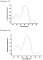
- 238000000862 absorption spectrum Methods 0.000 description 44
- XLOMVQKBTHCTTD-UHFFFAOYSA-N Zinc monoxide Chemical compound [Zn]=O XLOMVQKBTHCTTD-UHFFFAOYSA-N 0.000 description 39
- 238000002371 ultraviolet--visible spectrum Methods 0.000 description 38
- 238000006243 chemical reaction Methods 0.000 description 33
- 239000000758 substrate Substances 0.000 description 27
- KFZMGEQAYNKOFK-UHFFFAOYSA-N Isopropanol Chemical compound CC(C)O KFZMGEQAYNKOFK-UHFFFAOYSA-N 0.000 description 25
- 239000000463 material Substances 0.000 description 25
- 239000011248 coating agent Substances 0.000 description 24
- 238000000576 coating method Methods 0.000 description 24
- 238000004768 lowest unoccupied molecular orbital Methods 0.000 description 23
- 239000010408 film Substances 0.000 description 22
- 238000000034 method Methods 0.000 description 22
- 238000005259 measurement Methods 0.000 description 20
- 238000010521 absorption reaction Methods 0.000 description 19
- MCEWYIDBDVPMES-UHFFFAOYSA-N [60]pcbm Chemical compound C123C(C4=C5C6=C7C8=C9C%10=C%11C%12=C%13C%14=C%15C%16=C%17C%18=C(C=%19C=%20C%18=C%18C%16=C%13C%13=C%11C9=C9C7=C(C=%20C9=C%13%18)C(C7=%19)=C96)C6=C%11C%17=C%15C%13=C%15C%14=C%12C%12=C%10C%10=C85)=C9C7=C6C2=C%11C%13=C2C%15=C%12C%10=C4C23C1(CCCC(=O)OC)C1=CC=CC=C1 MCEWYIDBDVPMES-UHFFFAOYSA-N 0.000 description 18
- 125000001424 substituent group Chemical group 0.000 description 18
- 239000011787 zinc oxide Substances 0.000 description 18
- 125000004432 carbon atom Chemical group C* 0.000 description 17
- USIUVYZYUHIAEV-UHFFFAOYSA-N diphenyl ether Chemical compound C=1C=CC=CC=1OC1=CC=CC=C1 USIUVYZYUHIAEV-UHFFFAOYSA-N 0.000 description 16
- XXZCIYUJYUESMD-UHFFFAOYSA-N 2-[4-[2-(2,3-dihydro-1H-inden-2-ylamino)pyrimidin-5-yl]-3-(morpholin-4-ylmethyl)pyrazol-1-yl]-1-(2,4,6,7-tetrahydrotriazolo[4,5-c]pyridin-5-yl)ethanone Chemical compound C1C(CC2=CC=CC=C12)NC1=NC=C(C=N1)C=1C(=NN(C=1)CC(=O)N1CC2=C(CC1)NN=N2)CN1CCOCC1 XXZCIYUJYUESMD-UHFFFAOYSA-N 0.000 description 14
- JKQOBWVOAYFWKG-UHFFFAOYSA-N molybdenum trioxide Chemical compound O=[Mo](=O)=O JKQOBWVOAYFWKG-UHFFFAOYSA-N 0.000 description 14
- 0 CC**C(CC1=C*=CCC1)=I Chemical compound CC**C(CC1=C*=CCC1)=I 0.000 description 13
- 125000004435 hydrogen atom Chemical group [H]* 0.000 description 13
- CSCPPACGZOOCGX-UHFFFAOYSA-N Acetone Chemical compound CC(C)=O CSCPPACGZOOCGX-UHFFFAOYSA-N 0.000 description 12
- 238000010438 heat treatment Methods 0.000 description 11
- RTZKZFJDLAIYFH-UHFFFAOYSA-N Diethyl ether Chemical compound CCOCC RTZKZFJDLAIYFH-UHFFFAOYSA-N 0.000 description 9
- 230000015572 biosynthetic process Effects 0.000 description 9
- 125000001153 fluoro group Chemical group F* 0.000 description 9
- 230000001965 increasing effect Effects 0.000 description 9
- 239000002904 solvent Substances 0.000 description 9
- 238000003786 synthesis reaction Methods 0.000 description 9
- 238000002207 thermal evaporation Methods 0.000 description 9
- JTPNRXUCIXHOKM-UHFFFAOYSA-N 1-chloronaphthalene Chemical compound C1=CC=C2C(Cl)=CC=CC2=C1 JTPNRXUCIXHOKM-UHFFFAOYSA-N 0.000 description 8
- CBENFWSGALASAD-UHFFFAOYSA-N Ozone Chemical compound [O-][O+]=O CBENFWSGALASAD-UHFFFAOYSA-N 0.000 description 8
- 239000000178 monomer Substances 0.000 description 8
- KZDTZHQLABJVLE-UHFFFAOYSA-N 1,8-diiodooctane Chemical compound ICCCCCCCCI KZDTZHQLABJVLE-UHFFFAOYSA-N 0.000 description 7
- 239000011521 glass Substances 0.000 description 7
- 239000000203 mixture Substances 0.000 description 7
- NPHULPIAPWNOOH-UHFFFAOYSA-N 2-[4-[2-(2,3-dihydro-1H-inden-2-ylamino)pyrimidin-5-yl]-3-(2,3-dihydroindol-1-ylmethyl)pyrazol-1-yl]-1-(2,4,6,7-tetrahydrotriazolo[4,5-c]pyridin-5-yl)ethanone Chemical compound C1C(CC2=CC=CC=C12)NC1=NC=C(C=N1)C=1C(=NN(C=1)CC(=O)N1CC2=C(CC1)NN=N2)CN1CCC2=CC=CC=C12 NPHULPIAPWNOOH-UHFFFAOYSA-N 0.000 description 6
- 150000001875 compounds Chemical class 0.000 description 6
- 238000002347 injection Methods 0.000 description 6
- 239000007924 injection Substances 0.000 description 6
- 229910052751 metal Inorganic materials 0.000 description 6
- 239000002184 metal Substances 0.000 description 6
- XMWRBQBLMFGWIX-UHFFFAOYSA-N C60 fullerene Chemical compound C12=C3C(C4=C56)=C7C8=C5C5=C9C%10=C6C6=C4C1=C1C4=C6C6=C%10C%10=C9C9=C%11C5=C8C5=C8C7=C3C3=C7C2=C1C1=C2C4=C6C4=C%10C6=C9C9=C%11C5=C5C8=C3C3=C7C1=C1C2=C4C6=C2C9=C5C3=C12 XMWRBQBLMFGWIX-UHFFFAOYSA-N 0.000 description 5
- 239000012153 distilled water Substances 0.000 description 5
- XLYOFNOQVPJJNP-UHFFFAOYSA-N water Chemical compound O XLYOFNOQVPJJNP-UHFFFAOYSA-N 0.000 description 5
- WLNFHSOQOLOFQO-UHFFFAOYSA-N 5,6-difluoro-4,7-diiodo-2,1,3-benzothiadiazole Chemical compound IC1=C(F)C(F)=C(I)C2=NSN=C21 WLNFHSOQOLOFQO-UHFFFAOYSA-N 0.000 description 4
- HEDRZPFGACZZDS-UHFFFAOYSA-N Chloroform Chemical compound ClC(Cl)Cl HEDRZPFGACZZDS-UHFFFAOYSA-N 0.000 description 4
- LRHPLDYGYMQRHN-UHFFFAOYSA-N N-Butanol Chemical compound CCCCO LRHPLDYGYMQRHN-UHFFFAOYSA-N 0.000 description 4
- 125000003368 amide group Chemical group 0.000 description 4
- 125000000484 butyl group Chemical group [H]C([*])([H])C([H])([H])C([H])([H])C([H])([H])[H] 0.000 description 4
- 125000004051 hexyl group Chemical group [H]C([H])([H])C([H])([H])C([H])([H])C([H])([H])C([H])([H])C([H])([H])* 0.000 description 4
- 125000002347 octyl group Chemical group [H]C([*])([H])C([H])([H])C([H])([H])C([H])([H])C([H])([H])C([H])([H])C([H])([H])C([H])([H])[H] 0.000 description 4
- 239000002243 precursor Substances 0.000 description 4
- 230000032258 transport Effects 0.000 description 4
- ONGNEJPRRURZEY-UHFFFAOYSA-N 3-(2-ethyldecyl)thiophene Chemical compound C(C)C(CC1=CSC=C1)CCCCCCCC ONGNEJPRRURZEY-UHFFFAOYSA-N 0.000 description 3
- LEWKFGOZTUSUMV-UHFFFAOYSA-N C[Sn](C=1SC=C(C=1)CC(CCCCCCCC)CC)(C)C Chemical compound C[Sn](C=1SC=C(C=1)CC(CCCCCCCC)CC)(C)C LEWKFGOZTUSUMV-UHFFFAOYSA-N 0.000 description 3
- 229920000144 PEDOT:PSS Polymers 0.000 description 3
- 238000006619 Stille reaction Methods 0.000 description 3
- YTPLMLYBLZKORZ-UHFFFAOYSA-N Thiophene Chemical group C=1C=CSC=1 YTPLMLYBLZKORZ-UHFFFAOYSA-N 0.000 description 3
- YXFVVABEGXRONW-UHFFFAOYSA-N Toluene Chemical compound CC1=CC=CC=C1 YXFVVABEGXRONW-UHFFFAOYSA-N 0.000 description 3
- 125000005332 alkyl sulfoxy group Chemical group 0.000 description 3
- 125000005377 alkyl thioxy group Chemical group 0.000 description 3
- 229910052782 aluminium Inorganic materials 0.000 description 3
- 125000003277 amino group Chemical group 0.000 description 3
- 125000005165 aryl thioxy group Chemical group 0.000 description 3
- 125000004104 aryloxy group Chemical group 0.000 description 3
- 125000004429 atom Chemical group 0.000 description 3
- 125000006267 biphenyl group Chemical group 0.000 description 3
- 239000000470 constituent Substances 0.000 description 3
- 229960004132 diethyl ether Drugs 0.000 description 3
- 125000003438 dodecyl group Chemical group [H]C([H])([H])C([H])([H])C([H])([H])C([H])([H])C([H])([H])C([H])([H])C([H])([H])C([H])([H])C([H])([H])C([H])([H])C([H])([H])C([H])([H])* 0.000 description 3
- 230000000694 effects Effects 0.000 description 3
- 125000003983 fluorenyl group Chemical group C1(=CC=CC=2C3=CC=CC=C3CC12)* 0.000 description 3
- 125000005462 imide group Chemical group 0.000 description 3
- 230000004048 modification Effects 0.000 description 3
- 238000012986 modification Methods 0.000 description 3
- VLKZOEOYAKHREP-UHFFFAOYSA-N n-Hexane Chemical compound CCCCCC VLKZOEOYAKHREP-UHFFFAOYSA-N 0.000 description 3
- 125000004108 n-butyl group Chemical group [H]C([H])([H])C([H])([H])C([H])([H])C([H])([H])* 0.000 description 3
- 125000001280 n-hexyl group Chemical group C(CCCCC)* 0.000 description 3
- 230000001590 oxidative effect Effects 0.000 description 3
- 229910052760 oxygen Inorganic materials 0.000 description 3
- 238000005191 phase separation Methods 0.000 description 3
- 238000002360 preparation method Methods 0.000 description 3
- 230000008569 process Effects 0.000 description 3
- 239000004065 semiconductor Substances 0.000 description 3
- VXWYQEYFYNAZOD-UHFFFAOYSA-N 2-[3-[(4,4-difluoropiperidin-1-yl)methyl]-4-[2-(2,3-dihydro-1H-inden-2-ylamino)pyrimidin-5-yl]pyrazol-1-yl]-1-(2,4,6,7-tetrahydrotriazolo[4,5-c]pyridin-5-yl)ethanone Chemical compound FC1(F)CCN(CC2=NN(CC(=O)N3CCC4=C(C3)N=NN4)C=C2C2=CN=C(NC3CC4=C(C3)C=CC=C4)N=C2)CC1 VXWYQEYFYNAZOD-UHFFFAOYSA-N 0.000 description 2
- 125000005916 2-methylpentyl group Chemical group 0.000 description 2
- OKTJSMMVPCPJKN-UHFFFAOYSA-N Carbon Chemical compound [C] OKTJSMMVPCPJKN-UHFFFAOYSA-N 0.000 description 2
- 229920002284 Cellulose triacetate Polymers 0.000 description 2
- YLQBMQCUIZJEEH-UHFFFAOYSA-N Furan Chemical group C=1C=COC=1 YLQBMQCUIZJEEH-UHFFFAOYSA-N 0.000 description 2
- 239000004693 Polybenzimidazole Substances 0.000 description 2
- 229920002873 Polyethylenimine Polymers 0.000 description 2
- 239000004642 Polyimide Substances 0.000 description 2
- 239000004743 Polypropylene Substances 0.000 description 2
- 238000006069 Suzuki reaction reaction Methods 0.000 description 2
- WYURNTSHIVDZCO-UHFFFAOYSA-N Tetrahydrofuran Chemical compound C1CCOC1 WYURNTSHIVDZCO-UHFFFAOYSA-N 0.000 description 2
- GWEVSGVZZGPLCZ-UHFFFAOYSA-N Titan oxide Chemical compound O=[Ti]=O GWEVSGVZZGPLCZ-UHFFFAOYSA-N 0.000 description 2
- NNLVGZFZQQXQNW-ADJNRHBOSA-N [(2r,3r,4s,5r,6s)-4,5-diacetyloxy-3-[(2s,3r,4s,5r,6r)-3,4,5-triacetyloxy-6-(acetyloxymethyl)oxan-2-yl]oxy-6-[(2r,3r,4s,5r,6s)-4,5,6-triacetyloxy-2-(acetyloxymethyl)oxan-3-yl]oxyoxan-2-yl]methyl acetate Chemical compound O([C@@H]1O[C@@H]([C@H]([C@H](OC(C)=O)[C@H]1OC(C)=O)O[C@H]1[C@@H]([C@@H](OC(C)=O)[C@H](OC(C)=O)[C@@H](COC(C)=O)O1)OC(C)=O)COC(=O)C)[C@@H]1[C@@H](COC(C)=O)O[C@@H](OC(C)=O)[C@H](OC(C)=O)[C@H]1OC(C)=O NNLVGZFZQQXQNW-ADJNRHBOSA-N 0.000 description 2
- 125000003342 alkenyl group Chemical group 0.000 description 2
- 229910045601 alloy Inorganic materials 0.000 description 2
- 239000000956 alloy Substances 0.000 description 2
- 229910001632 barium fluoride Inorganic materials 0.000 description 2
- 230000008901 benefit Effects 0.000 description 2
- 238000009835 boiling Methods 0.000 description 2
- FJDQFPXHSGXQBY-UHFFFAOYSA-L caesium carbonate Chemical compound [Cs+].[Cs+].[O-]C([O-])=O FJDQFPXHSGXQBY-UHFFFAOYSA-L 0.000 description 2
- 229910000024 caesium carbonate Inorganic materials 0.000 description 2
- 239000011575 calcium Substances 0.000 description 2
- 238000004440 column chromatography Methods 0.000 description 2
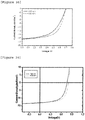
- 238000002484 cyclic voltammetry Methods 0.000 description 2
- 125000000753 cycloalkyl group Chemical group 0.000 description 2
- 230000003247 decreasing effect Effects 0.000 description 2
- 229910003472 fullerene Inorganic materials 0.000 description 2
- 125000005842 heteroatom Chemical group 0.000 description 2
- 229910052744 lithium Inorganic materials 0.000 description 2
- 239000011777 magnesium Substances 0.000 description 2
- 229910044991 metal oxide Inorganic materials 0.000 description 2
- 150000004706 metal oxides Chemical class 0.000 description 2
- 229910000476 molybdenum oxide Inorganic materials 0.000 description 2
- 125000002950 monocyclic group Chemical group 0.000 description 2
- 239000002105 nanoparticle Substances 0.000 description 2
- 229910000480 nickel oxide Inorganic materials 0.000 description 2
- 125000004433 nitrogen atom Chemical group N* 0.000 description 2
- 239000001301 oxygen Substances 0.000 description 2
- 125000002080 perylenyl group Chemical group C1(=CC=C2C=CC=C3C4=CC=CC5=CC=CC(C1=C23)=C45)* 0.000 description 2
- 125000001997 phenyl group Chemical group [H]C1=C([H])C([H])=C(*)C([H])=C1[H] 0.000 description 2
- BASFCYQUMIYNBI-UHFFFAOYSA-N platinum Chemical compound [Pt] BASFCYQUMIYNBI-UHFFFAOYSA-N 0.000 description 2
- 229920002480 polybenzimidazole Polymers 0.000 description 2
- 125000003367 polycyclic group Chemical group 0.000 description 2
- 229920000139 polyethylene terephthalate Polymers 0.000 description 2
- 239000005020 polyethylene terephthalate Substances 0.000 description 2
- 229920001721 polyimide Polymers 0.000 description 2
- 229920001155 polypropylene Polymers 0.000 description 2
- 238000002203 pretreatment Methods 0.000 description 2
- 238000010992 reflux Methods 0.000 description 2
- 238000007650 screen-printing Methods 0.000 description 2
- 238000004528 spin coating Methods 0.000 description 2
- 125000001973 tert-pentyl group Chemical group [H]C([H])([H])C([H])([H])C(*)(C([H])([H])[H])C([H])([H])[H] 0.000 description 2
- XOLBLPGZBRYERU-UHFFFAOYSA-N tin dioxide Chemical compound O=[Sn]=O XOLBLPGZBRYERU-UHFFFAOYSA-N 0.000 description 2
- OGIDPMRJRNCKJF-UHFFFAOYSA-N titanium oxide Inorganic materials [Ti]=O OGIDPMRJRNCKJF-UHFFFAOYSA-N 0.000 description 2
- 125000001425 triazolyl group Chemical group 0.000 description 2
- JYEUMXHLPRZUAT-UHFFFAOYSA-N 1,2,3-triazine Chemical group C1=CN=NN=C1 JYEUMXHLPRZUAT-UHFFFAOYSA-N 0.000 description 1
- AJKNNUJQFALRIK-UHFFFAOYSA-N 1,2,3-trifluorobenzene Chemical group FC1=CC=CC(F)=C1F AJKNNUJQFALRIK-UHFFFAOYSA-N 0.000 description 1
- YJTKZCDBKVTVBY-UHFFFAOYSA-N 1,3-Diphenylbenzene Chemical group C1=CC=CC=C1C1=CC=CC(C=2C=CC=CC=2)=C1 YJTKZCDBKVTVBY-UHFFFAOYSA-N 0.000 description 1
- 125000000355 1,3-benzoxazolyl group Chemical group O1C(=NC2=C1C=CC=C2)* 0.000 description 1
- FCEHBMOGCRZNNI-UHFFFAOYSA-N 1-benzothiophene Chemical group C1=CC=C2SC=CC2=C1 FCEHBMOGCRZNNI-UHFFFAOYSA-N 0.000 description 1
- 125000004973 1-butenyl group Chemical group C(=CCC)* 0.000 description 1
- 125000006218 1-ethylbutyl group Chemical group [H]C([H])([H])C([H])([H])C([H])([H])C([H])(*)C([H])([H])C([H])([H])[H] 0.000 description 1
- 125000006023 1-pentenyl group Chemical group 0.000 description 1
- 125000006017 1-propenyl group Chemical group 0.000 description 1
- MYKQKWIPLZEVOW-UHFFFAOYSA-N 11h-benzo[a]carbazole Chemical group C1=CC2=CC=CC=C2C2=C1C1=CC=CC=C1N2 MYKQKWIPLZEVOW-UHFFFAOYSA-N 0.000 description 1
- AVPWUAFYDNQGNZ-UHFFFAOYSA-N 2,3,4,5-tetrabromothiophene Chemical compound BrC=1SC(Br)=C(Br)C=1Br AVPWUAFYDNQGNZ-UHFFFAOYSA-N 0.000 description 1
- STTGYIUESPWXOW-UHFFFAOYSA-N 2,9-dimethyl-4,7-diphenyl-1,10-phenanthroline Chemical compound C=12C=CC3=C(C=4C=CC=CC=4)C=C(C)N=C3C2=NC(C)=CC=1C1=CC=CC=C1 STTGYIUESPWXOW-UHFFFAOYSA-N 0.000 description 1
- 125000004974 2-butenyl group Chemical group C(C=CC)* 0.000 description 1
- 125000006176 2-ethylbutyl group Chemical group [H]C([H])([H])C([H])([H])C([H])(C([H])([H])*)C([H])([H])C([H])([H])[H] 0.000 description 1
- WONYVCKUEUULQN-UHFFFAOYSA-N 2-methyl-n-(2-methylphenyl)aniline Chemical group CC1=CC=CC=C1NC1=CC=CC=C1C WONYVCKUEUULQN-UHFFFAOYSA-N 0.000 description 1
- JTMODJXOTWYBOZ-UHFFFAOYSA-N 2-methyl-n-phenylaniline Chemical group CC1=CC=CC=C1NC1=CC=CC=C1 JTMODJXOTWYBOZ-UHFFFAOYSA-N 0.000 description 1
- 125000006024 2-pentenyl group Chemical group 0.000 description 1
- 125000003903 2-propenyl group Chemical group [H]C([*])([H])C([H])=C([H])[H] 0.000 description 1
- DHHCELFFCVACQR-UHFFFAOYSA-N 3-(bromomethyl)undecane Chemical compound CCCCCCCCC(CC)CBr DHHCELFFCVACQR-UHFFFAOYSA-N 0.000 description 1
- XCMISAPCWHTVNG-UHFFFAOYSA-N 3-bromothiophene Chemical compound BrC=1C=CSC=1 XCMISAPCWHTVNG-UHFFFAOYSA-N 0.000 description 1
- 125000004975 3-butenyl group Chemical group C(CC=C)* 0.000 description 1
- 125000006027 3-methyl-1-butenyl group Chemical group 0.000 description 1
- LGGRWCVLGMUDND-UHFFFAOYSA-N 4,7-bis[4-(2-ethyldecyl)thiophen-2-yl]-5,6-difluoro-2,1,3-benzothiadiazole Chemical compound FC1=C(C=2C(=NSN=2)C(=C1F)C=1SC=C(C=1)CC(CCCCCCCC)CC)C=1SC=C(C=1)CC(CCCCCCCC)CC LGGRWCVLGMUDND-UHFFFAOYSA-N 0.000 description 1
- JDUYPUMQALQRCN-UHFFFAOYSA-N 4-bromophenyl phenyl ether Chemical compound C1=CC(Br)=CC=C1OC1=CC=CC=C1 JDUYPUMQALQRCN-UHFFFAOYSA-N 0.000 description 1
- 125000004920 4-methyl-2-pentyl group Chemical group CC(CC(C)*)C 0.000 description 1
- XQNMSKCVXVXEJT-UHFFFAOYSA-N 7,14,25,32-tetrazaundecacyclo[21.13.2.22,5.03,19.04,16.06,14.08,13.020,37.024,32.026,31.034,38]tetraconta-1(36),2,4,6,8,10,12,16,18,20(37),21,23(38),24,26,28,30,34,39-octadecaene-15,33-dione 7,14,25,32-tetrazaundecacyclo[21.13.2.22,5.03,19.04,16.06,14.08,13.020,37.025,33.026,31.034,38]tetraconta-1(37),2,4,6,8,10,12,16,18,20,22,26,28,30,32,34(38),35,39-octadecaene-15,24-dione Chemical compound O=c1c2ccc3c4ccc5c6nc7ccccc7n6c(=O)c6ccc(c7ccc(c8nc9ccccc9n18)c2c37)c4c56.O=c1c2ccc3c4ccc5c6c(ccc(c7ccc(c8nc9ccccc9n18)c2c37)c46)c1nc2ccccc2n1c5=O XQNMSKCVXVXEJT-UHFFFAOYSA-N 0.000 description 1
- ZCYVEMRRCGMTRW-UHFFFAOYSA-N 7553-56-2 Chemical compound [I] ZCYVEMRRCGMTRW-UHFFFAOYSA-N 0.000 description 1
- 239000005725 8-Hydroxyquinoline Substances 0.000 description 1
- QXDWMAODKPOTKK-UHFFFAOYSA-N 9-methylanthracen-1-amine Chemical group C1=CC(N)=C2C(C)=C(C=CC=C3)C3=CC2=C1 QXDWMAODKPOTKK-UHFFFAOYSA-N 0.000 description 1
- NOWKCMXCCJGMRR-UHFFFAOYSA-N Aziridine Chemical compound C1CN1 NOWKCMXCCJGMRR-UHFFFAOYSA-N 0.000 description 1
- ROFVEXUMMXZLPA-UHFFFAOYSA-N Bipyridyl Chemical group N1=CC=CC=C1C1=CC=CC=N1 ROFVEXUMMXZLPA-UHFFFAOYSA-N 0.000 description 1
- WKBOTKDWSSQWDR-UHFFFAOYSA-N Bromine atom Chemical compound [Br] WKBOTKDWSSQWDR-UHFFFAOYSA-N 0.000 description 1
- OYPRJOBELJOOCE-UHFFFAOYSA-N Calcium Chemical compound [Ca] OYPRJOBELJOOCE-UHFFFAOYSA-N 0.000 description 1
- ZAMOUSCENKQFHK-UHFFFAOYSA-N Chlorine atom Chemical compound [Cl] ZAMOUSCENKQFHK-UHFFFAOYSA-N 0.000 description 1
- VYZAMTAEIAYCRO-UHFFFAOYSA-N Chromium Chemical compound [Cr] VYZAMTAEIAYCRO-UHFFFAOYSA-N 0.000 description 1
- RYGMFSIKBFXOCR-UHFFFAOYSA-N Copper Chemical compound [Cu] RYGMFSIKBFXOCR-UHFFFAOYSA-N 0.000 description 1
- MYMOFIZGZYHOMD-UHFFFAOYSA-N Dioxygen Chemical compound O=O MYMOFIZGZYHOMD-UHFFFAOYSA-N 0.000 description 1
- QUSNBJAOOMFDIB-UHFFFAOYSA-N Ethylamine Chemical group CCN QUSNBJAOOMFDIB-UHFFFAOYSA-N 0.000 description 1
- 229910052688 Gadolinium Inorganic materials 0.000 description 1
- 238000003747 Grignard reaction Methods 0.000 description 1
- 239000007818 Grignard reagent Substances 0.000 description 1
- DGAQECJNVWCQMB-PUAWFVPOSA-M Ilexoside XXIX Chemical compound C[C@@H]1CC[C@@]2(CC[C@@]3(C(=CC[C@H]4[C@]3(CC[C@@H]5[C@@]4(CC[C@@H](C5(C)C)OS(=O)(=O)[O-])C)C)[C@@H]2[C@]1(C)O)C)C(=O)O[C@H]6[C@@H]([C@H]([C@@H]([C@H](O6)CO)O)O)O.[Na+] DGAQECJNVWCQMB-PUAWFVPOSA-M 0.000 description 1
- WHXSMMKQMYFTQS-UHFFFAOYSA-N Lithium Chemical compound [Li] WHXSMMKQMYFTQS-UHFFFAOYSA-N 0.000 description 1
- FYYHWMGAXLPEAU-UHFFFAOYSA-N Magnesium Chemical compound [Mg] FYYHWMGAXLPEAU-UHFFFAOYSA-N 0.000 description 1
- XQVWYOYUZDUNRW-UHFFFAOYSA-N N-Phenyl-1-naphthylamine Chemical group C=1C=CC2=CC=CC=C2C=1NC1=CC=CC=C1 XQVWYOYUZDUNRW-UHFFFAOYSA-N 0.000 description 1
- NFHFRUOZVGFOOS-UHFFFAOYSA-N Pd(PPh3)4 Substances [Pd].C1=CC=CC=C1P(C=1C=CC=CC=1)C1=CC=CC=C1.C1=CC=CC=C1P(C=1C=CC=CC=1)C1=CC=CC=C1.C1=CC=CC=C1P(C=1C=CC=CC=1)C1=CC=CC=C1.C1=CC=CC=C1P(C=1C=CC=CC=1)C1=CC=CC=C1 NFHFRUOZVGFOOS-UHFFFAOYSA-N 0.000 description 1
- ZLMJMSJWJFRBEC-UHFFFAOYSA-N Potassium Chemical compound [K] ZLMJMSJWJFRBEC-UHFFFAOYSA-N 0.000 description 1
- BQCADISMDOOEFD-UHFFFAOYSA-N Silver Chemical compound [Ag] BQCADISMDOOEFD-UHFFFAOYSA-N 0.000 description 1
- FZWLAAWBMGSTSO-UHFFFAOYSA-N Thiazole Chemical group C1=CSC=N1 FZWLAAWBMGSTSO-UHFFFAOYSA-N 0.000 description 1
- ATJFFYVFTNAWJD-UHFFFAOYSA-N Tin Chemical compound [Sn] ATJFFYVFTNAWJD-UHFFFAOYSA-N 0.000 description 1
- RTAQQCXQSZGOHL-UHFFFAOYSA-N Titanium Chemical compound [Ti] RTAQQCXQSZGOHL-UHFFFAOYSA-N 0.000 description 1
- HCHKCACWOHOZIP-UHFFFAOYSA-N Zinc Chemical compound [Zn] HCHKCACWOHOZIP-UHFFFAOYSA-N 0.000 description 1
- DGEZNRSVGBDHLK-UHFFFAOYSA-N [1,10]phenanthroline Chemical group C1=CN=C2C3=NC=CC=C3C=CC2=C1 DGEZNRSVGBDHLK-UHFFFAOYSA-N 0.000 description 1
- 238000005804 alkylation reaction Methods 0.000 description 1
- XAGFODPZIPBFFR-UHFFFAOYSA-N aluminium Chemical compound [Al] XAGFODPZIPBFFR-UHFFFAOYSA-N 0.000 description 1
- 125000002490 anilino group Chemical group [H]N(*)C1=C([H])C([H])=C([H])C([H])=C1[H] 0.000 description 1
- YUENFNPLGJCNRB-UHFFFAOYSA-N anthracen-1-amine Chemical group C1=CC=C2C=C3C(N)=CC=CC3=CC2=C1 YUENFNPLGJCNRB-UHFFFAOYSA-N 0.000 description 1
- 125000002178 anthracenyl group Chemical group C1(=CC=CC2=CC3=CC=CC=C3C=C12)* 0.000 description 1
- 125000003710 aryl alkyl group Chemical group 0.000 description 1
- QVGXLLKOCUKJST-UHFFFAOYSA-N atomic oxygen Chemical compound [O] QVGXLLKOCUKJST-UHFFFAOYSA-N 0.000 description 1
- 125000003785 benzimidazolyl group Chemical group N1=C(NC2=C1C=CC=C2)* 0.000 description 1
- 125000000499 benzofuranyl group Chemical group O1C(=CC2=C1C=CC=C2)* 0.000 description 1
- IOJUPLGTWVMSFF-UHFFFAOYSA-N benzothiazole Chemical group C1=CC=C2SC=NC2=C1 IOJUPLGTWVMSFF-UHFFFAOYSA-N 0.000 description 1
- 125000006616 biphenylamine group Chemical group 0.000 description 1
- ZADPBFCGQRWHPN-UHFFFAOYSA-N boronic acid Chemical compound OBO ZADPBFCGQRWHPN-UHFFFAOYSA-N 0.000 description 1
- GDTBXPJZTBHREO-UHFFFAOYSA-N bromine Substances BrBr GDTBXPJZTBHREO-UHFFFAOYSA-N 0.000 description 1
- 229910052794 bromium Inorganic materials 0.000 description 1
- 229910052791 calcium Inorganic materials 0.000 description 1
- 238000004364 calculation method Methods 0.000 description 1
- 125000000609 carbazolyl group Chemical group C1(=CC=CC=2C3=CC=CC=C3NC12)* 0.000 description 1
- 150000001721 carbon Chemical group 0.000 description 1
- CREMABGTGYGIQB-UHFFFAOYSA-N carbon carbon Chemical compound C.C CREMABGTGYGIQB-UHFFFAOYSA-N 0.000 description 1
- 239000011203 carbon fibre reinforced carbon Substances 0.000 description 1
- 239000000460 chlorine Substances 0.000 description 1
- 229910052801 chlorine Inorganic materials 0.000 description 1
- KWTSZCJMWHGPOS-UHFFFAOYSA-M chloro(trimethyl)stannane Chemical compound C[Sn](C)(C)Cl KWTSZCJMWHGPOS-UHFFFAOYSA-M 0.000 description 1
- 229910052804 chromium Inorganic materials 0.000 description 1
- 239000011651 chromium Substances 0.000 description 1
- 125000002676 chrysenyl group Chemical group C1(=CC=CC=2C3=CC=C4C=CC=CC4=C3C=CC12)* 0.000 description 1
- 238000004140 cleaning Methods 0.000 description 1
- 239000012459 cleaning agent Substances 0.000 description 1
- 229920001940 conductive polymer Polymers 0.000 description 1
- 229910052802 copper Inorganic materials 0.000 description 1
- 239000010949 copper Substances 0.000 description 1
- 238000005859 coupling reaction Methods 0.000 description 1
- 238000004132 cross linking Methods 0.000 description 1
- 239000013078 crystal Substances 0.000 description 1
- 229910021419 crystalline silicon Inorganic materials 0.000 description 1
- 238000002425 crystallisation Methods 0.000 description 1
- 230000008025 crystallization Effects 0.000 description 1
- 125000006165 cyclic alkyl group Chemical group 0.000 description 1
- 125000004122 cyclic group Chemical group 0.000 description 1
- 125000001995 cyclobutyl group Chemical group [H]C1([H])C([H])([H])C([H])(*)C1([H])[H] 0.000 description 1
- 125000000582 cycloheptyl group Chemical group [H]C1([H])C([H])([H])C([H])([H])C([H])([H])C([H])(*)C([H])([H])C1([H])[H] 0.000 description 1
- 125000000113 cyclohexyl group Chemical group [H]C1([H])C([H])([H])C([H])([H])C([H])(*)C([H])([H])C1([H])[H] 0.000 description 1
- 125000004210 cyclohexylmethyl group Chemical group [H]C([H])(*)C1([H])C([H])([H])C([H])([H])C([H])([H])C([H])([H])C1([H])[H] 0.000 description 1
- 125000000640 cyclooctyl group Chemical group [H]C1([H])C([H])([H])C([H])([H])C([H])([H])C([H])(*)C([H])([H])C([H])([H])C1([H])[H] 0.000 description 1
- 125000001511 cyclopentyl group Chemical group [H]C1([H])C([H])([H])C([H])([H])C([H])(*)C1([H])[H] 0.000 description 1
- 125000004851 cyclopentylmethyl group Chemical group C1(CCCC1)C* 0.000 description 1
- 125000001559 cyclopropyl group Chemical group [H]C1([H])C([H])([H])C1([H])* 0.000 description 1
- 230000007423 decrease Effects 0.000 description 1
- SWXVUIWOUIDPGS-UHFFFAOYSA-N diacetone alcohol Natural products CC(=O)CC(C)(C)O SWXVUIWOUIDPGS-UHFFFAOYSA-N 0.000 description 1
- IYYZUPMFVPLQIF-ALWQSETLSA-N dibenzothiophene Chemical group C1=CC=CC=2[34S]C3=C(C=21)C=CC=C3 IYYZUPMFVPLQIF-ALWQSETLSA-N 0.000 description 1
- ZBQUMMFUJLOTQC-UHFFFAOYSA-L dichloronickel;3-diphenylphosphanylpropyl(diphenyl)phosphane Chemical compound Cl[Ni]Cl.C=1C=CC=CC=1P(C=1C=CC=CC=1)CCCP(C=1C=CC=CC=1)C1=CC=CC=C1 ZBQUMMFUJLOTQC-UHFFFAOYSA-L 0.000 description 1
- 125000001664 diethylamino group Chemical group [H]C([H])([H])C([H])([H])N(*)C([H])([H])C([H])([H])[H] 0.000 description 1
- 125000002147 dimethylamino group Chemical group [H]C([H])([H])N(*)C([H])([H])[H] 0.000 description 1
- 229910001882 dioxygen Inorganic materials 0.000 description 1
- 238000003618 dip coating Methods 0.000 description 1
- DMBHHRLKUKUOEG-UHFFFAOYSA-N diphenylamine Chemical group C=1C=CC=CC=1NC1=CC=CC=C1 DMBHHRLKUKUOEG-UHFFFAOYSA-N 0.000 description 1
- GNTDGMZSJNCJKK-UHFFFAOYSA-N divanadium pentaoxide Chemical compound O=[V](=O)O[V](=O)=O GNTDGMZSJNCJKK-UHFFFAOYSA-N 0.000 description 1
- 230000005684 electric field Effects 0.000 description 1
- 238000002848 electrochemical method Methods 0.000 description 1
- 238000005516 engineering process Methods 0.000 description 1
- 125000001495 ethyl group Chemical group [H]C([H])([H])C([H])([H])* 0.000 description 1
- 239000000284 extract Substances 0.000 description 1
- 238000000605 extraction Methods 0.000 description 1
- KTWOOEGAPBSYNW-UHFFFAOYSA-N ferrocene Chemical compound [Fe+2].C=1C=C[CH-]C=1.C=1C=C[CH-]C=1 KTWOOEGAPBSYNW-UHFFFAOYSA-N 0.000 description 1
- 239000000706 filtrate Substances 0.000 description 1
- UIWYJDYFSGRHKR-UHFFFAOYSA-N gadolinium atom Chemical compound [Gd] UIWYJDYFSGRHKR-UHFFFAOYSA-N 0.000 description 1
- PCHJSUWPFVWCPO-UHFFFAOYSA-N gold Chemical compound [Au] PCHJSUWPFVWCPO-UHFFFAOYSA-N 0.000 description 1
- 229910052737 gold Inorganic materials 0.000 description 1
- 239000010931 gold Substances 0.000 description 1
- 238000007646 gravure printing Methods 0.000 description 1
- 150000004795 grignard reagents Chemical class 0.000 description 1
- 125000003187 heptyl group Chemical group [H]C([*])([H])C([H])([H])C([H])([H])C([H])([H])C([H])([H])C([H])([H])C([H])([H])[H] 0.000 description 1
- 150000002431 hydrogen Chemical group 0.000 description 1
- 125000002883 imidazolyl group Chemical group 0.000 description 1
- 230000006872 improvement Effects 0.000 description 1
- 229910052738 indium Inorganic materials 0.000 description 1
- APFVFJFRJDLVQX-UHFFFAOYSA-N indium atom Chemical compound [In] APFVFJFRJDLVQX-UHFFFAOYSA-N 0.000 description 1
- 229910003437 indium oxide Inorganic materials 0.000 description 1
- PJXISJQVUVHSOJ-UHFFFAOYSA-N indium(iii) oxide Chemical compound [O-2].[O-2].[O-2].[In+3].[In+3] PJXISJQVUVHSOJ-UHFFFAOYSA-N 0.000 description 1
- AMGQUBHHOARCQH-UHFFFAOYSA-N indium;oxotin Chemical compound [In].[Sn]=O AMGQUBHHOARCQH-UHFFFAOYSA-N 0.000 description 1
- 125000001041 indolyl group Chemical group 0.000 description 1
- 230000001939 inductive effect Effects 0.000 description 1
- 238000007641 inkjet printing Methods 0.000 description 1
- 230000003993 interaction Effects 0.000 description 1
- 239000011630 iodine Substances 0.000 description 1
- 229910052740 iodine Inorganic materials 0.000 description 1
- 229910052742 iron Inorganic materials 0.000 description 1
- 125000000959 isobutyl group Chemical group [H]C([H])([H])C([H])(C([H])([H])[H])C([H])([H])* 0.000 description 1
- 125000004491 isohexyl group Chemical group C(CCC(C)C)* 0.000 description 1
- 125000001972 isopentyl group Chemical group [H]C([H])([H])C([H])(C([H])([H])[H])C([H])([H])C([H])([H])* 0.000 description 1
- 125000000555 isopropenyl group Chemical group [H]\C([H])=C(\*)C([H])([H])[H] 0.000 description 1
- 125000001449 isopropyl group Chemical group [H]C([H])([H])C([H])(*)C([H])([H])[H] 0.000 description 1
- 125000002183 isoquinolinyl group Chemical group C1(=NC=CC2=CC=CC=C12)* 0.000 description 1
- 125000000842 isoxazolyl group Chemical group 0.000 description 1
- 239000007788 liquid Substances 0.000 description 1
- DLEDOFVPSDKWEF-UHFFFAOYSA-N lithium butane Chemical compound [Li+].CCC[CH2-] DLEDOFVPSDKWEF-UHFFFAOYSA-N 0.000 description 1
- 230000007774 longterm Effects 0.000 description 1
- 229910052749 magnesium Inorganic materials 0.000 description 1
- 125000002496 methyl group Chemical group [H]C([H])([H])* 0.000 description 1
- 125000000250 methylamino group Chemical group [H]N(*)C([H])([H])[H] 0.000 description 1
- 125000004170 methylsulfonyl group Chemical group [H]C([H])([H])S(*)(=O)=O 0.000 description 1
- 238000002715 modification method Methods 0.000 description 1
- MZRVEZGGRBJDDB-UHFFFAOYSA-N n-Butyllithium Substances [Li]CCCC MZRVEZGGRBJDDB-UHFFFAOYSA-N 0.000 description 1
- 125000003136 n-heptyl group Chemical group [H]C([H])([H])C([H])([H])C([H])([H])C([H])([H])C([H])([H])C([H])([H])C([H])([H])* 0.000 description 1
- 125000000740 n-pentyl group Chemical group [H]C([H])([H])C([H])([H])C([H])([H])C([H])([H])C([H])([H])* 0.000 description 1
- 125000004123 n-propyl group Chemical group [H]C([H])([H])C([H])([H])C([H])([H])* 0.000 description 1
- 125000001624 naphthyl group Chemical group 0.000 description 1
- 125000005184 naphthylamino group Chemical group C1(=CC=CC2=CC=CC=C12)N* 0.000 description 1
- 125000001971 neopentyl group Chemical group [H]C([*])([H])C(C([H])([H])[H])(C([H])([H])[H])C([H])([H])[H] 0.000 description 1
- 125000002560 nitrile group Chemical group 0.000 description 1
- 125000000449 nitro group Chemical group [O-][N+](*)=O 0.000 description 1
- 229910052757 nitrogen Inorganic materials 0.000 description 1
- QGLKJKCYBOYXKC-UHFFFAOYSA-N nonaoxidotritungsten Chemical compound O=[W]1(=O)O[W](=O)(=O)O[W](=O)(=O)O1 QGLKJKCYBOYXKC-UHFFFAOYSA-N 0.000 description 1
- WKVAXZCSIOTXBT-UHFFFAOYSA-N octane-1,1-dithiol Chemical compound CCCCCCCC(S)S WKVAXZCSIOTXBT-UHFFFAOYSA-N 0.000 description 1
- 238000013086 organic photovoltaic Methods 0.000 description 1
- 239000003960 organic solvent Substances 0.000 description 1
- WCPAKWJPBJAGKN-UHFFFAOYSA-N oxadiazole Chemical group C1=CON=N1 WCPAKWJPBJAGKN-UHFFFAOYSA-N 0.000 description 1
- 125000002971 oxazolyl group Chemical group 0.000 description 1
- 230000003647 oxidation Effects 0.000 description 1
- 238000007254 oxidation reaction Methods 0.000 description 1
- PQQKPALAQIIWST-UHFFFAOYSA-N oxomolybdenum Chemical compound [Mo]=O PQQKPALAQIIWST-UHFFFAOYSA-N 0.000 description 1
- GNRSAWUEBMWBQH-UHFFFAOYSA-N oxonickel Chemical compound [Ni]=O GNRSAWUEBMWBQH-UHFFFAOYSA-N 0.000 description 1
- 125000004430 oxygen atom Chemical group O* 0.000 description 1
- 229960003540 oxyquinoline Drugs 0.000 description 1
- 238000010422 painting Methods 0.000 description 1
- 125000003538 pentan-3-yl group Chemical group [H]C([H])([H])C([H])([H])C([H])(*)C([H])([H])C([H])([H])[H] 0.000 description 1
- 125000001147 pentyl group Chemical group C(CCCC)* 0.000 description 1
- CSHWQDPOILHKBI-UHFFFAOYSA-N peryrene Natural products C1=CC(C2=CC=CC=3C2=C2C=CC=3)=C3C2=CC=CC3=C1 CSHWQDPOILHKBI-UHFFFAOYSA-N 0.000 description 1
- 125000005561 phenanthryl group Chemical group 0.000 description 1
- 125000001484 phenothiazinyl group Chemical group C1(=CC=CC=2SC3=CC=CC=C3NC12)* 0.000 description 1
- 125000004592 phthalazinyl group Chemical group C1(=NN=CC2=CC=CC=C12)* 0.000 description 1
- 229920003023 plastic Polymers 0.000 description 1
- 229910052697 platinum Inorganic materials 0.000 description 1
- 229920001467 poly(styrenesulfonates) Polymers 0.000 description 1
- 229920000767 polyaniline Polymers 0.000 description 1
- 239000011112 polyethylene naphthalate Substances 0.000 description 1
- 238000006116 polymerization reaction Methods 0.000 description 1
- 230000000379 polymerizing effect Effects 0.000 description 1
- 229920000128 polypyrrole Polymers 0.000 description 1
- 229910052700 potassium Inorganic materials 0.000 description 1
- 239000011591 potassium Substances 0.000 description 1
- 239000002244 precipitate Substances 0.000 description 1
- 239000000047 product Substances 0.000 description 1
- 125000001436 propyl group Chemical group [H]C([*])([H])C([H])([H])C([H])([H])[H] 0.000 description 1
- 125000003373 pyrazinyl group Chemical group 0.000 description 1
- 125000001725 pyrenyl group Chemical group 0.000 description 1
- PBMFSQRYOILNGV-UHFFFAOYSA-N pyridazine Chemical group C1=CC=NN=C1 PBMFSQRYOILNGV-UHFFFAOYSA-N 0.000 description 1
- 125000004076 pyridyl group Chemical group 0.000 description 1
- 125000000714 pyrimidinyl group Chemical group 0.000 description 1
- 125000000168 pyrrolyl group Chemical group 0.000 description 1
- 125000002294 quinazolinyl group Chemical group N1=C(N=CC2=CC=CC=C12)* 0.000 description 1
- MCJGNVYPOGVAJF-UHFFFAOYSA-N quinolin-8-ol Chemical compound C1=CN=C2C(O)=CC=CC2=C1 MCJGNVYPOGVAJF-UHFFFAOYSA-N 0.000 description 1
- 125000001567 quinoxalinyl group Chemical group N1=C(C=NC2=CC=CC=C12)* 0.000 description 1
- 230000006798 recombination Effects 0.000 description 1
- 238000005215 recombination Methods 0.000 description 1
- 125000002914 sec-butyl group Chemical group [H]C([H])([H])C([H])([H])C([H])(*)C([H])([H])[H] 0.000 description 1
- 125000003548 sec-pentyl group Chemical group [H]C([H])([H])C([H])([H])C([H])([H])C([H])(*)C([H])([H])[H] 0.000 description 1
- 229910052709 silver Inorganic materials 0.000 description 1
- 239000004332 silver Substances 0.000 description 1
- 229910052708 sodium Inorganic materials 0.000 description 1
- 239000011734 sodium Substances 0.000 description 1
- 239000007787 solid Substances 0.000 description 1
- 238000005507 spraying Methods 0.000 description 1
- 238000004544 sputter deposition Methods 0.000 description 1
- 238000003756 stirring Methods 0.000 description 1
- 125000003011 styrenyl group Chemical group [H]\C(*)=C(/[H])C1=C([H])C([H])=C([H])C([H])=C1[H] 0.000 description 1
- 238000006467 substitution reaction Methods 0.000 description 1
- 238000010301 surface-oxidation reaction Methods 0.000 description 1
- 125000000999 tert-butyl group Chemical group [H]C([H])([H])C(*)(C([H])([H])[H])C([H])([H])[H] 0.000 description 1
- 125000001113 thiadiazolyl group Chemical group 0.000 description 1
- 229930192474 thiophene Natural products 0.000 description 1
- 229910052718 tin Inorganic materials 0.000 description 1
- 239000010936 titanium Substances 0.000 description 1
- 229910052719 titanium Inorganic materials 0.000 description 1
- TVIVIEFSHFOWTE-UHFFFAOYSA-K tri(quinolin-8-yloxy)alumane Chemical class [Al+3].C1=CN=C2C([O-])=CC=CC2=C1.C1=CN=C2C([O-])=CC=CC2=C1.C1=CN=C2C([O-])=CC=CC2=C1 TVIVIEFSHFOWTE-UHFFFAOYSA-K 0.000 description 1
- PIILXFBHQILWPS-UHFFFAOYSA-N tributyltin Chemical compound CCCC[Sn](CCCC)CCCC PIILXFBHQILWPS-UHFFFAOYSA-N 0.000 description 1
- 125000006617 triphenylamine group Chemical group 0.000 description 1
- COIOYMYWGDAQPM-UHFFFAOYSA-N tris(2-methylphenyl)phosphane Chemical compound CC1=CC=CC=C1P(C=1C(=CC=CC=1)C)C1=CC=CC=C1C COIOYMYWGDAQPM-UHFFFAOYSA-N 0.000 description 1
- 229910001930 tungsten oxide Inorganic materials 0.000 description 1
- 238000007514 turning Methods 0.000 description 1
- 229910052720 vanadium Inorganic materials 0.000 description 1
- GPPXJZIENCGNKB-UHFFFAOYSA-N vanadium Chemical compound [V]#[V] GPPXJZIENCGNKB-UHFFFAOYSA-N 0.000 description 1
- 125000000391 vinyl group Chemical group [H]C([*])=C([H])[H] 0.000 description 1
- 229920002554 vinyl polymer Polymers 0.000 description 1
- 238000004078 waterproofing Methods 0.000 description 1
- 229910052727 yttrium Inorganic materials 0.000 description 1
- VWQVUPCCIRVNHF-UHFFFAOYSA-N yttrium atom Chemical compound [Y] VWQVUPCCIRVNHF-UHFFFAOYSA-N 0.000 description 1
- 229910052725 zinc Inorganic materials 0.000 description 1
- 239000011701 zinc Substances 0.000 description 1
- YVTHLONGBIQYBO-UHFFFAOYSA-N zinc indium(3+) oxygen(2-) Chemical compound [O--].[Zn++].[In+3] YVTHLONGBIQYBO-UHFFFAOYSA-N 0.000 description 1
Images


Classifications
-
- H—ELECTRICITY
- H10—SEMICONDUCTOR DEVICES; ELECTRIC SOLID-STATE DEVICES NOT OTHERWISE PROVIDED FOR
- H10K—ORGANIC ELECTRIC SOLID-STATE DEVICES
- H10K85/00—Organic materials used in the body or electrodes of devices covered by this subclass
- H10K85/10—Organic polymers or oligomers
- H10K85/111—Organic polymers or oligomers comprising aromatic, heteroaromatic, or aryl chains, e.g. polyaniline, polyphenylene or polyphenylene vinylene
- H10K85/113—Heteroaromatic compounds comprising sulfur or selene, e.g. polythiophene
-
- C—CHEMISTRY; METALLURGY
- C08—ORGANIC MACROMOLECULAR COMPOUNDS; THEIR PREPARATION OR CHEMICAL WORKING-UP; COMPOSITIONS BASED THEREON
- C08G—MACROMOLECULAR COMPOUNDS OBTAINED OTHERWISE THAN BY REACTIONS ONLY INVOLVING UNSATURATED CARBON-TO-CARBON BONDS
- C08G61/00—Macromolecular compounds obtained by reactions forming a carbon-to-carbon link in the main chain of the macromolecule
- C08G61/12—Macromolecular compounds containing atoms other than carbon in the main chain of the macromolecule
- C08G61/122—Macromolecular compounds containing atoms other than carbon in the main chain of the macromolecule derived from five- or six-membered heterocyclic compounds, other than imides
- C08G61/123—Macromolecular compounds containing atoms other than carbon in the main chain of the macromolecule derived from five- or six-membered heterocyclic compounds, other than imides derived from five-membered heterocyclic compounds
- C08G61/126—Macromolecular compounds containing atoms other than carbon in the main chain of the macromolecule derived from five- or six-membered heterocyclic compounds, other than imides derived from five-membered heterocyclic compounds with a five-membered ring containing one sulfur atom in the ring
-
- H—ELECTRICITY
- H01—ELECTRIC ELEMENTS
- H01L—SEMICONDUCTOR DEVICES NOT COVERED BY CLASS H10
- H01L31/00—Semiconductor devices sensitive to infrared radiation, light, electromagnetic radiation of shorter wavelength or corpuscular radiation and specially adapted either for the conversion of the energy of such radiation into electrical energy or for the control of electrical energy by such radiation; Processes or apparatus specially adapted for the manufacture or treatment thereof or of parts thereof; Details thereof
- H01L31/04—Semiconductor devices sensitive to infrared radiation, light, electromagnetic radiation of shorter wavelength or corpuscular radiation and specially adapted either for the conversion of the energy of such radiation into electrical energy or for the control of electrical energy by such radiation; Processes or apparatus specially adapted for the manufacture or treatment thereof or of parts thereof; Details thereof adapted as photovoltaic [PV] conversion devices
- H01L31/042—PV modules or arrays of single PV cells
-
- H—ELECTRICITY
- H10—SEMICONDUCTOR DEVICES; ELECTRIC SOLID-STATE DEVICES NOT OTHERWISE PROVIDED FOR
- H10K—ORGANIC ELECTRIC SOLID-STATE DEVICES
- H10K85/00—Organic materials used in the body or electrodes of devices covered by this subclass
- H10K85/10—Organic polymers or oligomers
- H10K85/151—Copolymers
-
- C—CHEMISTRY; METALLURGY
- C08—ORGANIC MACROMOLECULAR COMPOUNDS; THEIR PREPARATION OR CHEMICAL WORKING-UP; COMPOSITIONS BASED THEREON
- C08G—MACROMOLECULAR COMPOUNDS OBTAINED OTHERWISE THAN BY REACTIONS ONLY INVOLVING UNSATURATED CARBON-TO-CARBON BONDS
- C08G2261/00—Macromolecular compounds obtained by reactions forming a carbon-to-carbon link in the main chain of the macromolecule
- C08G2261/10—Definition of the polymer structure
- C08G2261/12—Copolymers
- C08G2261/122—Copolymers statistical
-
- C—CHEMISTRY; METALLURGY
- C08—ORGANIC MACROMOLECULAR COMPOUNDS; THEIR PREPARATION OR CHEMICAL WORKING-UP; COMPOSITIONS BASED THEREON
- C08G—MACROMOLECULAR COMPOUNDS OBTAINED OTHERWISE THAN BY REACTIONS ONLY INVOLVING UNSATURATED CARBON-TO-CARBON BONDS
- C08G2261/00—Macromolecular compounds obtained by reactions forming a carbon-to-carbon link in the main chain of the macromolecule
- C08G2261/10—Definition of the polymer structure
- C08G2261/14—Side-groups
- C08G2261/141—Side-chains having aliphatic units
- C08G2261/1412—Saturated aliphatic units
-
- C—CHEMISTRY; METALLURGY
- C08—ORGANIC MACROMOLECULAR COMPOUNDS; THEIR PREPARATION OR CHEMICAL WORKING-UP; COMPOSITIONS BASED THEREON
- C08G—MACROMOLECULAR COMPOUNDS OBTAINED OTHERWISE THAN BY REACTIONS ONLY INVOLVING UNSATURATED CARBON-TO-CARBON BONDS
- C08G2261/00—Macromolecular compounds obtained by reactions forming a carbon-to-carbon link in the main chain of the macromolecule
- C08G2261/10—Definition of the polymer structure
- C08G2261/14—Side-groups
- C08G2261/142—Side-chains containing oxygen
- C08G2261/1424—Side-chains containing oxygen containing ether groups, including alkoxy
-
- C—CHEMISTRY; METALLURGY
- C08—ORGANIC MACROMOLECULAR COMPOUNDS; THEIR PREPARATION OR CHEMICAL WORKING-UP; COMPOSITIONS BASED THEREON
- C08G—MACROMOLECULAR COMPOUNDS OBTAINED OTHERWISE THAN BY REACTIONS ONLY INVOLVING UNSATURATED CARBON-TO-CARBON BONDS
- C08G2261/00—Macromolecular compounds obtained by reactions forming a carbon-to-carbon link in the main chain of the macromolecule
- C08G2261/10—Definition of the polymer structure
- C08G2261/14—Side-groups
- C08G2261/146—Side-chains containing halogens
-
- C—CHEMISTRY; METALLURGY
- C08—ORGANIC MACROMOLECULAR COMPOUNDS; THEIR PREPARATION OR CHEMICAL WORKING-UP; COMPOSITIONS BASED THEREON
- C08G—MACROMOLECULAR COMPOUNDS OBTAINED OTHERWISE THAN BY REACTIONS ONLY INVOLVING UNSATURATED CARBON-TO-CARBON BONDS
- C08G2261/00—Macromolecular compounds obtained by reactions forming a carbon-to-carbon link in the main chain of the macromolecule
- C08G2261/10—Definition of the polymer structure
- C08G2261/18—Definition of the polymer structure conjugated
-
- C—CHEMISTRY; METALLURGY
- C08—ORGANIC MACROMOLECULAR COMPOUNDS; THEIR PREPARATION OR CHEMICAL WORKING-UP; COMPOSITIONS BASED THEREON
- C08G—MACROMOLECULAR COMPOUNDS OBTAINED OTHERWISE THAN BY REACTIONS ONLY INVOLVING UNSATURATED CARBON-TO-CARBON BONDS
- C08G2261/00—Macromolecular compounds obtained by reactions forming a carbon-to-carbon link in the main chain of the macromolecule
- C08G2261/30—Monomer units or repeat units incorporating structural elements in the main chain
- C08G2261/32—Monomer units or repeat units incorporating structural elements in the main chain incorporating heteroaromatic structural elements in the main chain
- C08G2261/322—Monomer units or repeat units incorporating structural elements in the main chain incorporating heteroaromatic structural elements in the main chain non-condensed
- C08G2261/3223—Monomer units or repeat units incorporating structural elements in the main chain incorporating heteroaromatic structural elements in the main chain non-condensed containing one or more sulfur atoms as the only heteroatom, e.g. thiophene
-
- C—CHEMISTRY; METALLURGY
- C08—ORGANIC MACROMOLECULAR COMPOUNDS; THEIR PREPARATION OR CHEMICAL WORKING-UP; COMPOSITIONS BASED THEREON
- C08G—MACROMOLECULAR COMPOUNDS OBTAINED OTHERWISE THAN BY REACTIONS ONLY INVOLVING UNSATURATED CARBON-TO-CARBON BONDS
- C08G2261/00—Macromolecular compounds obtained by reactions forming a carbon-to-carbon link in the main chain of the macromolecule
- C08G2261/30—Monomer units or repeat units incorporating structural elements in the main chain
- C08G2261/32—Monomer units or repeat units incorporating structural elements in the main chain incorporating heteroaromatic structural elements in the main chain
- C08G2261/324—Monomer units or repeat units incorporating structural elements in the main chain incorporating heteroaromatic structural elements in the main chain condensed
- C08G2261/3246—Monomer units or repeat units incorporating structural elements in the main chain incorporating heteroaromatic structural elements in the main chain condensed containing nitrogen and sulfur as heteroatoms
-
- C—CHEMISTRY; METALLURGY
- C08—ORGANIC MACROMOLECULAR COMPOUNDS; THEIR PREPARATION OR CHEMICAL WORKING-UP; COMPOSITIONS BASED THEREON
- C08G—MACROMOLECULAR COMPOUNDS OBTAINED OTHERWISE THAN BY REACTIONS ONLY INVOLVING UNSATURATED CARBON-TO-CARBON BONDS
- C08G2261/00—Macromolecular compounds obtained by reactions forming a carbon-to-carbon link in the main chain of the macromolecule
- C08G2261/40—Polymerisation processes
- C08G2261/41—Organometallic coupling reactions
- C08G2261/414—Stille reactions
-
- C—CHEMISTRY; METALLURGY
- C08—ORGANIC MACROMOLECULAR COMPOUNDS; THEIR PREPARATION OR CHEMICAL WORKING-UP; COMPOSITIONS BASED THEREON
- C08G—MACROMOLECULAR COMPOUNDS OBTAINED OTHERWISE THAN BY REACTIONS ONLY INVOLVING UNSATURATED CARBON-TO-CARBON BONDS
- C08G2261/00—Macromolecular compounds obtained by reactions forming a carbon-to-carbon link in the main chain of the macromolecule
- C08G2261/50—Physical properties
- C08G2261/51—Charge transport
- C08G2261/512—Hole transport
-
- C—CHEMISTRY; METALLURGY
- C08—ORGANIC MACROMOLECULAR COMPOUNDS; THEIR PREPARATION OR CHEMICAL WORKING-UP; COMPOSITIONS BASED THEREON
- C08G—MACROMOLECULAR COMPOUNDS OBTAINED OTHERWISE THAN BY REACTIONS ONLY INVOLVING UNSATURATED CARBON-TO-CARBON BONDS
- C08G2261/00—Macromolecular compounds obtained by reactions forming a carbon-to-carbon link in the main chain of the macromolecule
- C08G2261/90—Applications
- C08G2261/91—Photovoltaic applications
-
- H—ELECTRICITY
- H10—SEMICONDUCTOR DEVICES; ELECTRIC SOLID-STATE DEVICES NOT OTHERWISE PROVIDED FOR
- H10K—ORGANIC ELECTRIC SOLID-STATE DEVICES
- H10K30/00—Organic devices sensitive to infrared radiation, light, electromagnetic radiation of shorter wavelength or corpuscular radiation
- H10K30/30—Organic devices sensitive to infrared radiation, light, electromagnetic radiation of shorter wavelength or corpuscular radiation comprising bulk heterojunctions, e.g. interpenetrating networks of donor and acceptor material domains
-
- H—ELECTRICITY
- H10—SEMICONDUCTOR DEVICES; ELECTRIC SOLID-STATE DEVICES NOT OTHERWISE PROVIDED FOR
- H10K—ORGANIC ELECTRIC SOLID-STATE DEVICES
- H10K30/00—Organic devices sensitive to infrared radiation, light, electromagnetic radiation of shorter wavelength or corpuscular radiation
- H10K30/50—Photovoltaic [PV] devices
-
- H—ELECTRICITY
- H10—SEMICONDUCTOR DEVICES; ELECTRIC SOLID-STATE DEVICES NOT OTHERWISE PROVIDED FOR
- H10K—ORGANIC ELECTRIC SOLID-STATE DEVICES
- H10K85/00—Organic materials used in the body or electrodes of devices covered by this subclass
- H10K85/10—Organic polymers or oligomers
- H10K85/111—Organic polymers or oligomers comprising aromatic, heteroaromatic, or aryl chains, e.g. polyaniline, polyphenylene or polyphenylene vinylene
- H10K85/113—Heteroaromatic compounds comprising sulfur or selene, e.g. polythiophene
- H10K85/1135—Polyethylene dioxythiophene [PEDOT]; Derivatives thereof
-
- Y—GENERAL TAGGING OF NEW TECHNOLOGICAL DEVELOPMENTS; GENERAL TAGGING OF CROSS-SECTIONAL TECHNOLOGIES SPANNING OVER SEVERAL SECTIONS OF THE IPC; TECHNICAL SUBJECTS COVERED BY FORMER USPC CROSS-REFERENCE ART COLLECTIONS [XRACs] AND DIGESTS
- Y02—TECHNOLOGIES OR APPLICATIONS FOR MITIGATION OR ADAPTATION AGAINST CLIMATE CHANGE
- Y02E—REDUCTION OF GREENHOUSE GAS [GHG] EMISSIONS, RELATED TO ENERGY GENERATION, TRANSMISSION OR DISTRIBUTION
- Y02E10/00—Energy generation through renewable energy sources
- Y02E10/50—Photovoltaic [PV] energy
- Y02E10/549—Organic PV cells
-
- Y—GENERAL TAGGING OF NEW TECHNOLOGICAL DEVELOPMENTS; GENERAL TAGGING OF CROSS-SECTIONAL TECHNOLOGIES SPANNING OVER SEVERAL SECTIONS OF THE IPC; TECHNICAL SUBJECTS COVERED BY FORMER USPC CROSS-REFERENCE ART COLLECTIONS [XRACs] AND DIGESTS
- Y02—TECHNOLOGIES OR APPLICATIONS FOR MITIGATION OR ADAPTATION AGAINST CLIMATE CHANGE
- Y02P—CLIMATE CHANGE MITIGATION TECHNOLOGIES IN THE PRODUCTION OR PROCESSING OF GOODS
- Y02P70/00—Climate change mitigation technologies in the production process for final industrial or consumer products
- Y02P70/50—Manufacturing or production processes characterised by the final manufactured product
Definitions
- the present specification relates to a polymer and an organic solar cell including the same.
- An organic solar cell is a device that may directly convert solar energy into electric energy by applying a photovoltaic effect.
- a solar cell may be divided into an inorganic solar cell and an organic solar cell, depending on the materials constituting a thin film.
- Typical solar cells are made through a p-n junction by doping crystalline silicon (Si), which is an inorganic semiconductor. Electrons and holes generated by absorbing light diffuse to p-n junction points and move to an electrode while being accelerated by the electric field.
- the power conversion efficiency in this process is defined as the ratio of electric power given to an external circuit and solar power entering the solar cell, and the efficiency have reached approximately 24% when measured under a currently standardized virtual solar irradiation condition.
- inorganic solar cells in the related art have already shown the limitation in economic feasibility and material demands and supplies, an organic semiconductor solar cell, which is easily processed and inexpensive and has various functionalities, has come into the spotlight as a long-term alternative energy source.
- the solar cell it is important to increase efficiency so as to output as much electric energy as possible from solar energy.
- One of the reasons for the charge loss is the dissipation of generated electrons and holes due to recombination.
- Various methods have been proposed to deliver generated electrons and holes to an electrode without loss, but additional processes are required in most cases, and accordingly, manufacturing costs may be increased.
- An object of the present specification is to provide a polymer and an organic solar cell including the same.
- the present specification provides a polymer comprising: a first unit represented by the following Chemical Formula 1; and a second unit represented by the following Chemical Formula 2.
- X, X', X", and X"' are the same as or different from each other, and are each independently S or Se
- A1 and A2 are the same as or different from each other, and are each independently hydrogen
- A3 and A4 are the same as or different from each other, and are each independently hydrogen
- R1 to R8 are the same as or different from each other, and are each independently hydrogen; deuterium; a halogen group; a hydroxy group; a substituted or unsubstituted alkyl group; a substituted or unsubstituted alkoxy group; a substituted or unsubstituted aryl group; or a substituted or unsubstituted heterocyclic group, and a1 to a4 are each an integer
- an organic solar cell comprising: a first electrode; a second electrode which is disposed to face the first electrode; and an organic material layer having one or more layers which is disposed between the first electrode and the second electrode and includes a photoactive layer, in which one or more layers of the organic material layer include the above-described polymer.
- a polymer according to an exemplary embodiment of the present specification has an energy level of 700 nm or more, and thus may provide a device having high efficiency due to the high short-circuit current (J sc ). Further, the polymer according to an exemplary embodiment of the present specification has excellent solubility, and thus is economically efficient in terms of time and costs when a device is manufactured.
- the 'unit' means a repeated structure in which a monomer is included in a polymer, and a structure in which the monomer is bonded into the polymer by polymerization.
- the meaning of 'including a unit' means that the unit is included in a main chain in the polymer.
- the polymer includes the first unit represented by Chemical Formula 1 and the second unit represented by Chemical Formula 2.
- the polymer includes one or two or more first units represented by Chemical Formula 1 and one or two or more second units represented by Chemical Formula 2, which are included in the polymer.
- the two or more first units and/or second units when two or more first units and/or second units are included in the polymer, the two or more first units and/or second units may be the same as or different from each other.
- the first unit represented by Chemical Formula 1 includes fluorine
- the second unit represented by Chemical Formula 2 includes an alkoxy group or a thioether group. Accordingly, when the polymer simultaneously includes the first unit represented by Chemical Formula 1 and the second unit represented by Chemical Formula 2, the solubility of the polymer is excellent. In this case, there is an economic advantage in terms of time and/or costs when a device is manufactured.
- a polymer according to an exemplary embodiment of the present specification has an energy level of 700 nm or more, and thus may provide a device having high efficiency due to the high short-circuit current (J sc ).
- the polymer according to an exemplary embodiment of the present specification has excellent solubility, and thus is economically efficient in terms of time and costs when a device is manufactured.
- the second unit including -O-A3 and -OA4 increases a HOMO energy level value
- the first unit including A1 and A2 decreases a HOMO energy level value
- a high organic solar cell may be implemented by adjusting a ratio of the first unit and the second unit to adjust an appropriate HOMO energy level.
- the energy level means the size of energy. Accordingly, even when the energy level is expressed in the negative (-) direction from the vacuum level, it is interpreted that the energy level means an absolute value of the corresponding energy value.
- the HOMO energy level means the distance from the vacuum level to the highest occupied molecular orbital.
- the LUMO energy level means the distance from the vacuum level to the lowest unoccupied molecular orbital.
- the meaning of decreasing the HOMO energy level value means that the absolute value of the energy level is increased
- the meaning of increasing the HOMO energy level value means that the absolute value of the energy level is decreased.
- substitution means that a hydrogen atom bonded to a carbon atom of a compound is changed into another substituent, and a position to be substituted is not limited as long as the position is a position at which the hydrogen atom is substituted, that is, a position at which the substituent may be substituted, and when two or more are substituted, the two or more substituents may be the same as or different from each other.
- substituted or unsubstituted means being substituted with one or more substituents selected from the group consisting of deuterium; a halogen group; a nitrile group; a nitro group; an imide group; an amide group; a hydroxy group; a substituted or unsubstituted alkyl group; a substituted or unsubstituted cycloalkyl group; a substituted or unsubstituted alkoxy group; a substituted or unsubstituted aryloxy group; a substituted or unsubstituted alkylthioxy group; a substituted or unsubstituted arylthioxy group; a substituted or unsubstituted alkylsulfoxy group; a substituted or unsubstituted arylsulfoxy group; a substituted or unsubstituted alkenyl group; a substituted or unsubstituted aryl
- the substituent to which two or more substituents are linked may be a biphenyl group. That is, the biphenyl group may also be an aryl group, and may be interpreted as a substituent to which two phenyl groups are linked.
- the number of carbon atoms of an imide group is not particularly limited, but is preferably 1 to 30.
- the imide group may be a compound having the following structures, but is not limited thereto.
- an amide group one or two nitrogen atoms of the amide group may be substituted with hydrogen, a straight, branched, or cyclic alkyl group having 1 to 30 carbon atoms, or an aryl group having 6 to 30 carbon atoms.
- the amide group may be a compound having the following structural formulae, but is not limited thereto.
- examples of a halogen group include fluorine, chlorine, bromine or iodine.
- the alkyl group may be straight or branched, and the number of carbon atoms thereof is not particularly limited, but is preferably 1 to 50. Specific examples thereof include methyl, ethyl, propyl, n-propyl, isopropyl, butyl, n-butyl, isobutyl, tert-butyl, sec-butyl, 1-methyl-butyl, 1-ethyl-butyl, pentyl, n-pentyl, isopentyl, neopentyl, tert-pentyl, hexyl, n-hexyl, 1-methylpentyl, 2-methylpentyl, 4-methyl-2-pentyl, 3,3-dimethylbutyl, 2-ethylbutyl, heptyl, n-heptyl, 1-methylhexyl, cyclopentylmethyl, cyclohexylmethyl, octyl,
- a cycloalkyl group is not particularly limited, but the number of carbon atoms thereof is preferably 3 to 60, and specific examples thereof include cyclopropyl, cyclobutyl, cyclopentyl, 3-methylcyclopentyl, 2,3-dimethylcyclopentyl, cyclohexyl, 3-methylcyclohexyl, 4-methylcyclohexyl, 2,3-dimethylcyclohexyl, 3,4,5-trimethylcyclohexyl, 4-tert-butylcyclohexyl, cycloheptyl, cyclooctyl, and the like, but are not limited thereto.
- the alkoxy group may be straight, branched, or cyclic.
- the number of carbon atoms of the alkoxy group is not particularly limited, but is preferably 1 to 20. Specific examples thereof include methoxy, ethoxy, n-propoxy, isopropoxy, i-propyloxy, n-butoxy, isobutoxy, tert-butoxy, sec-butoxy, n-pentyloxy, neopentyloxy, isopentyloxy, n-hexyloxy, 3,3-dimethylbutyloxy, 2-ethylbutyloxy, n-octyloxy, n-nonyloxy, n-decyloxy, benzyloxy, p-methylbenzyloxy, and the like, but are not limited thereto.
- the alkenyl group may be straight or branched, and the number of carbon atoms thereof is not particularly limited, but is preferably 2 to 40.
- Specific examples thereof include vinyl, 1-propenyl, isopropenyl, 1-butenyl, 2-butenyl, 3-butenyl, 1-pentenyl, 2-pentenyl, 3-pentenyl, 3-methyl-1-butenyl, 1,3-butadienyl, allyl, 1-phenylvinyl-1-yl, 2-phenylvinyl-1-yl, 2,2-diphenylvinyl-1-yl, 2-phenyl-2-(naphthyl-1-yl)vinyl-1-yl, 2,2-bis(diphenyl-1-yl)vinyl-1-yl, a stilbenyl group, a styrenyl group, and the like, but are not limited thereto.
- the aryl group is a monocyclic aryl group
- the number of carbon atoms thereof is not particularly limited, but is preferably 6 to 25.
- Specific examples of the monocyclic aryl group include a phenyl group, a biphenyl group, a terphenyl group, and the like, but are not limited thereto.
- the aryl group is a polycyclic aryl group
- the number of carbon atoms thereof is not particularly limited, but is preferably 10 to 24.
- Specific examples of the polycyclic aryl group include a naphthyl group, an anthracenyl group, a phenanthryl group, a pyrenyl group, a perylenyl group, a chrysenyl group, a fluorenyl group, and the like, but are not limited thereto.
- the fluorenyl group may be substituted, and adjacent substituents may be bonded to each other to form a ring.
- the substituent may be and the like. However, the substituent is not limited thereto.
- a heterocyclic group includes one or more atoms other than carbon, that is, a heteroatom, and specifically, the heteroatom may include one or more atoms selected from the group consisting of O, N, Si, Se, S, and the like.
- the number of carbon atoms of the heterocyclic group is not particularly limited, but is preferably 2 to 60.
- heterocyclic group examples include a thiophene group, a furan group, a pyrrole group, an imidazole group, a thiazole group, an oxazole group, an oxadiazole group, a triazole group, a pyridyl group, a bipyridyl group, a pyrimidyl group, a triazine group, a triazole group, an acridyl group, a pyridazine group, a pyrazinyl group, a qinolinyl group, a quinazoline group, a quinoxalinyl group, a phthalazinyl group, a pyridopyrimidinyl group, a pyridopyrazinyl group, a pyrazinopyrazinyl group, an isoquinoline group, an indole group, a carbazole group, a benzoxazole group,
- the number of carbon atoms of an amine group is not particularly limited, but is preferably 1 to 30.
- An N atom in the amine group may be substituted with an aryl group, an alkyl group, an arylalkyl group, a heterocyclic group, and the like, and specific examples of the amine group include a methylamine group, a dimethylamine group, an ethylamine group, a diethylamine group, a phenylamine group, a naphthylamine group, a biphenylamine group, an anthracenylamine group, a 9-methyl-anthracenylamine group, a diphenylamine group, a phenylnaphthylamine group, a ditolylamine group, a phenyltolylamine group, a triphenylamine group, and the like, but are not limited thereto.
- the aryl group in the aryloxy group, the arylthioxy group, and the arylsulfoxy group is the same as the above-described examples of the aryl group.
- examples of the aryloxy group include phenoxy, p-tolyloxy, m-tolyloxy, 3,5-dimethyl-phenoxy, 2,4,6-trimethylphenoxy, p-tert-butylphenoxy, 3-biphenyloxy, 4-biphenyloxy, 1-naphthyloxy, 2-naphthyloxy, 4-methyl-1-naphthyloxy, 5-methyl-2-naphthyloxy, 1-anthryloxy, 2-anthryloxy, 9-anthryloxy, 1-phenanthryloxy, 3-phenanthryloxy, 9-phenanthryloxy, and the like
- examples of the arylthioxy group include a phenylthioxy group, a 2-methylphenylthioxy group, a
- the alkyl group in the alkylthioxy group and the alkylsulfoxy group is the same as the above-described examples of the alkyl group.
- examples of the alkylthioxy group include a methylthioxy group, an ethylthioxy group, a tert-butylthioxy group, a hexylthioxy group, an octylthioxy group, and the like
- examples of the alkylsulfoxy group include mesyl, an ethylsulfoxy group, a propylsulfoxy group, a butylsulfoxy group, and the like, but the examples are not limited thereto.
- a1 is 1.
- a2 is 1.
- R2 is hydrogen
- R3 is hydrogen
- one or two or more first units represented by Chemical Formula 1 is or are included.
- one or two or more units represented by Chemical Formula 2 is or are included.
- the first unit represented by Chemical Formula 1 is represented by the following Chemical Formula 1-1.
- X is S.
- X' is S.
- X is Se.
- X' is Se.
- A1 is hydrogen
- A1 is a halogen group.
- A1 is fluorine
- A2 is hydrogen
- A2 is a halogen group.
- A2 is fluorine
- the first unit represented by Chemical Formula 1-1 is represented by any one of the following Chemical Formulae 1-1-1 to 1-1-3.
- A3 is fluorine
- A4 is fluorine
- a3 is 0.
- a3 is 1.
- a4 is 0.
- a4 is 1.
- the second unit represented by Chemical Formula 2 is represented by the following Chemical Formula 2-1 or 2-2.
- a1 to a4 are 0 or 1.
- a1 to a4 when a1 to a4 are 1, the rotation of a molecule may be prevented, and the planarity may be increased through interaction of S or Se atoms of X to X'" with halogen groups of A1 and A2 or O atoms of Chemical Formula 2.
- X" is S.
- X" is Se.
- X"' is S.
- X"' is Se.
- the polymer further includes a third unit represented by any one of the following Chemical Formula 3.
- X3 to X6 are the same as or different from each other, and are each independently CR10R11, NR10, O, SiR10R11, PR10, S, GeR10R11, Se, or Te, Y5 and Y6 are the same as or different from each other, and are each independently CR12, N, SiR12, P, or GeR12 , b is an integer from 1 to 3, when b is an integer of 2 or more, two or more structures in the parenthesis are the same as or different from each other, and R10 to R14 are the same as or different from each other, and are each independently hydrogen; deuterium; a halogen group; a hydroxy group; a substituted or unsubstituted alkyl group; a substituted or unsubstituted alkoxy group; a substituted or unsubstituted thioether group; a substituted or unsubstituted aryl group; or a substituted or unsubstituted heterocycl
- X3 is S.
- Y5 is CR12.
- Y6 is CR12.
- R12 is hydrogen
- R12 is a halogen group.
- R12 is fluorine
- X3 is Se.
- X3 is GeR10R11.
- X4 is S.
- X4 is Se.
- X4 is Ge R10R11.
- X4 is NR10.
- X4 is SiR10R11.
- X4 is CR10R11.
- X4 is GeR10R11.
- X4 is CR10R11.
- X5 is S.
- X5 is O.
- X6 is S.
- Y5 is CR12.
- Y6 is CR12.
- the polymer further includes a third unit represented by any one of the following Chemical Formula 3-1.
- R10, R11, and R12 are the same as those described above, R12' is the same as the definition of R12, and the structures of Chemical Formula 3-1 may be each independently additionally unsubstituted or substituted with a substituent selected from the group consisting of deuterium; a halogen group; a hydroxy group; a substituted or unsubstituted alkyl group; a substituted or unsubstituted alkoxy group; a substituted or unsubstituted thioether group; a substituted or unsubstituted aryl group; and a substituted or unsubstituted heterocyclic group.
- the polymer including the first unit and the second unit is an alternate polymer.
- the polymer including the first unit and the second unit is a random polymer.
- the polymer includes a unit represented by any one of the following Chemical Formulae 4 to 7.
- a and A' are the same as or different from each other, and are each independently the first unit represented by Chemical Formula 1
- B is the second unit represented by Chemical Formula 2
- C, C', and C" are the same as or different from each other, and are each independently a third unit represented by any one of the following Chemical Formula 3, in Chemical Formula 3,
- X3 to X6 are the same as or different from each other, and are each independently CR10R11, NR10, O, SiR10R11, PR10, S, GeR10R11, Se, or Te
- Y5 and Y6 are the same as or different from each other, and are each independently CR12, N, SiR12, P, or GeR12
- b is an integer from 1 to 3, when b is an integer of 2 or more, two or more structures in the parenthesis are the same as or different from each other,
- R10 to R14 are the same as or different from each other, and are each independently hydrogen; deuterium; a halogen group; a hydroxy
- a polymer including the unit represented by Chemical Formula 4 may constitute an alternate polymer by including a unit composed only of the first unit and the second unit.
- a polymer including the unit represented by Chemical Formula 5 may constitute a random polymer by including a unit composed only of the first unit and the second unit, and the contents of the first unit and the second unit may be adjusted according to the molar ratio of 1 and m.
- a polymer including the unit represented by Chemical Formula 6 may constitute a random polymer by further including an additional unit in addition to the first unit and the second unit.
- a polymer including the unit represented by Chemical Formula 7 may constitute a random polymer by further including an additional unit in addition to the first unit and the second unit, which are the same as or different from each other.
- the unit represented by Chemical Formula 4 is represented by the following Chemical Formula 4-1.
- the unit represented by Chemical Formula 5 is represented by the following Chemical Formula 5-1.
- Chemical Formula 6 is represented by the following Chemical Formula 6-1.
- Chemical Formula 7 is represented by the following Chemical Formula 7-1.
- the polymer includes a unit represented by any one of the following Chemical Formula 4-1, Chemical Formula 5-1, Chemical Formula 6-1, and Chemical Formula 7-1.
- A1 to A4, R1, and R4 to R8 are the same as those defined in Chemical Formulae 1 and 2, A'1, A'2, R'1, and R'4 are the same as the definitions of A1, A2, R1, and R4 of Chemical Formula 1, R10 to R13, R'12, and R'13 are the same as or different from each other, and are each independently hydrogen; deuterium; a halogen group; a hydroxy group; a substituted or unsubstituted alkyl group; a substituted or unsubstituted alkoxy group; a substituted or unsubstituted aryl group; or a substituted or unsubstituted heterocyclic group, 1 is a molar ratio and 0 ⁇ 1 ⁇ 1, m is a molar ratio and 0 ⁇ m ⁇ 1, o is a molar ratio and 0 ⁇ o ⁇ 1, p is a molar ratio and 0 ⁇ 1 ⁇ 1,
- Ar3 and Ar4 are the same as or different from each other, and each independently a substituted or unsubstituted alkyl group.
- A3 and A4 are the same as or different from each other, and are each independently a substituted or unsubstituted alkyl group having 1 to 30 carbon atoms.
- A3 and A4 are a substituted or unsubstituted dodecyl group.
- A3 and A4 are a substituted or unsubstituted octyl group.
- A3 and A4 are a substituted or unsubstituted hexyl group.
- A3 and A4 are a substituted or unsubstituted butyl group.
- A3 is a dodecyl group.
- A4 is a dodecyl group.
- A3 is an n-dodecyl group.
- A4 is an n-dodecyl group.
- A3 is an octyl group.
- A4 is an octyl group.
- A3 is an n-octyl group.
- A4 is an n-octyl group.
- A3 is a hexyl group.
- A4 is a hexyl group.
- A3 is an n-hexyl group.
- A4 is an n-hexyl group.
- A3 is a butyl group.
- A4 is a butyl group.
- A3 is an n-butyl group.
- A4 is an n-butyl group.
- R1 and R4 are the same as or different from each other, and are each independently a substituted or unsubstituted alkyl group.
- R1 and R4 are the same as or different from each other, and are each independently a substituted or unsubstituted alkyl group having 1 to 30 carbon atoms.
- R1 and R4 are the same as or different from each other, and are each independently a substituted or unsubstituted straight or branched alkyl group having 1 to 30 carbon atoms.
- R1 and R4 are the same as or different from each other, and are each independently a substituted or unsubstituted 2-ethylhexyl group.
- R1 and R4 are the same as or different from each other, and are each independently a substituted or unsubstituted 2-octyldodecyl group.
- R1 and R4 are the same as or different from each other, and are each independently a substituted or unsubstituted 2-ethyldecyl group.
- R1 and R4 are the same as or different from each other, and are each independently a substituted or unsubstituted 2-butyloctyl group.
- R1 is a 2-ethylhexyl group.
- R4 is a 2-ethylhexyl group.
- R1 is a 2-octyldodecyl group.
- R4 is a 2-octyldodecyl group.
- R1 is a 2-ethyldecyl group.
- R4 is a 2-ethyldecyl group.
- R1 is a 2-butyloctyl group.
- R4 is a 2-butyloctyl group.
- R5 is hydrogen
- R5 is a halogen group.
- R5 is fluorine
- R6 is hydrogen
- R6 is a halogen group.
- R6 is fluorine
- R7 is hydrogen
- R7 is a halogen group.
- R7 is fluorine
- R8 is hydrogen
- R8 is a halogen group.
- R8 is fluorine
- R10 is hydrogen
- R10 is a halogen group.
- R10 is fluorine
- R11 is hydrogen
- R11 is a halogen group.
- R11 is fluorine
- R12 is hydrogen
- R12 is a halogen group.
- R12 is fluorine
- R13 is hydrogen
- R13 is a halogen group.
- R13 is fluorine
- A'1 is hydrogen
- A'1 is a halogen group.
- A'1 is fluorine
- A'2 is hydrogen
- A'2 is a halogen group.
- A'2 is fluorine
- R'1 and R'4 are the same as or different from each other, and are each independently a substituted or unsubstituted alkyl group.
- R'1 and R'4 are the same as or different from each other, and are each independently a substituted or unsubstituted alkyl group having 1 to 30 carbon atoms.
- R'1 and R'4 are the same as or different from each other, and are each independently a substituted or unsubstituted straight or branched alkyl group having 1 to 30 carbon atoms.
- R'1 and R'4 are the same as or different from each other, and are each independently a substituted or unsubstituted 2-ethylhexyl group.
- R'1 and R'4 are the same as or different from each other, and are each independently a substituted or unsubstituted 2-octyldodecyl group.
- R'1 and R'4 are the same as or different from each other, and are each independently a substituted or unsubstituted 2-ethyldecyl group.
- R'1 and R'4 are the same as or different from each other, and are each independently a substituted or unsubstituted 2-butyloctyl group.
- R'1 is a 2-ethylhexyl group.
- R'4 is a 2-ethylhexyl group.
- R'1 is a 2-octyldodecyl group.
- R'4 is a 2-octyldodecyl group.
- R'1 is a 2-ethyldecyl group.
- R'4 is a 2-ethyldecyl group.
- R'1 is a 2-butyloctyl group.
- R'4 is a 2-butyloctyl group.
- R'12 is hydrogen
- R'12 is a halogen group.
- R'12 is fluorine
- R'13 is hydrogen
- R'13 is a halogen group.
- R'13 is fluorine
- the polymer includes a unit represented by any one of the following Chemical Formulae 4-1-1 to 4-1-10, Chemical Formulae 5-1-1 to 5-1-3, Chemical Formulae 6-1-1 to 6-1-14, and Chemical Formulae 7-1-1 to 7-1-5.
- 1 is 0.5.
- 1 is 0.6.
- m is 0.5.
- m is 0.4.
- o is 0.5.
- p is 0.4.
- p 0.35.
- p is 0.3.
- p 0.25.
- p is 0.2.
- p 0.15.
- q is 0.1.
- q is 0.15.
- q is 0.2.
- q is 0.25.
- q is 0.3.
- q is 0.35.
- the HOMO energy level is 5 eV to 5.9 eV.
- the HOMO energy level was measured by means of a cyclic voltammetry which is an electrochemical method, and the LUMO energy level was measured as a difference between energy band gaps emitted from the HOMO energy to the UV edge.
- the cyclic voltammetry is composed of a working electrode which is a carbon electrode, a reference electrode, and a counter electrode which is a platinum plate, and is a method which measures electric current flowing in the electrodes while allowing the electric potential to fluctuate at a constant rate according to the time.
- the polymer has a solubility of 0.1 wt% to 20 wt% for chlorobenzene.
- the measurement of the solubility may mean a value measured at room temperature.
- an end group of the polymer a trifluoro-benzene group and/or 4-bromodiphenyl ether are/is used, but in general, an end group publicly known may be modified and used according to the need of a person with ordinary skill in the art, and the end group is not limited.
- the polymer has a number average molecular weight of preferably 5,000 g/mol to 1,000,000 g/mol.
- the polymer may have a molecular weight distribution of 1 to 10.
- the polymer has a molecular weight distribution of 1 to 3.
- the number average molecular weight is preferably 100,000 or less so that the polymer has predetermined or more solubility, and thus, a solution application method is advantageously applied.
- the polymer according to the present specification may be prepared by a multi-step chemical reaction. Monomers are prepared through an alkylation reaction, a Grignard reaction, a Suzuki coupling reaction, a Stille coupling reaction, and the like, and then final polymers may be prepared through a carbon-carbon coupling reaction such as a Stille coupling reaction.
- a substituent to be introduced is a boronic acid or boronic ester compound
- the final polymers may be prepared through a Suzuki coupling reaction
- a substituent to be introduced is a tributyltin or trimethyltin compound
- the final polymers may be prepared through a Stille coupling reaction, but the method is not limited thereto.
- An exemplary embodiment of the present specification provides an organic solar cell including: a first electrode; a second electrode which is disposed to face the first electrode; and an organic material layer having one or more layers which is disposed between the first electrode and the second electrode and includes a photoactive layer, in which one or more layers of the organic material layer include the polymer.
- the organic solar cell includes a first electrode, a photoactive layer, and a second electrode.
- the organic solar cell may further include a substrate, a hole transporting layer, and/or an electron transporting layer.
- an electron and a hole are generated between an electron donor and an electron acceptor.
- the generated hole is transported to a positive electrode through an electron donor layer.
- the organic material layer includes a hole transporting layer, a hole injection layer, or a layer which simultaneously transports and injects holes, and the hole transporting layer, the hole injection layer, or the layer which simultaneously transports and injects holes includes the polymer.
- the organic material layer includes an electron injection layer, an electron transporting layer, or a layer which simultaneously injects and transports electrons, and the electron injection layer, the electron transporting layer, or the layer which simultaneously injects and transports electrons includes the polymer.
- FIG. 1 is a view illustrating an organic solar cell according to an exemplary embodiment of the present specification.
- an electron and a hole are generated between an electron donor and an electron acceptor.
- the generated hole is transported to a positive electrode through an electron donor layer.
- the organic solar cell may further include an additional organic material layer.
- the organic solar cell may reduce the number of organic material layers by using an organic material which simultaneously has various functions.
- the first electrode is an anode
- the second electrode is a cathode
- the first electrode is a cathode
- the second electrode is an anode
- a cathode, a photoactive layer, and an anode may be arranged in this order, and an anode, a photoactive layer, and a cathode may be arranged in this order, but the arrangement order is not limited thereto.
- an anode, a hole transporting layer, a photoactive layer, an electron transporting layer, and a cathode may also be arranged in this order, and a cathode, an electron transporting layer, a photoactive layer, a hole transporting layer, and an anode may also be arranged in this order, but the arrangement order is not limited thereto.
- the organic solar cell has a normal structure.
- the normal structure may mean that an anode is formed on a substrate.
- a first electrode to be formed on a substrate may be an anode.
- the organic solar cell has an inverted structure.
- the inverted structure may mean that a cathode is formed on a substrate.
- a first electrode to be formed on a substrate may be a cathode.
- the organic solar cell has a tandem structure.
- the organic solar cell may include a photoactive layer having two or more layers.
- a photoactive layer may have one layer or two or more layers.
- a buffer layer may be disposed between a photoactive layer and a hole transporting layer, or between a photoactive layer and an electron transporting layer.
- a hole injection layer may be further disposed between an anode and a hole transporting layer.
- an electron injection layer may be further disposed between a cathode and an electron transporting layer.
- the photoactive layer includes one or two or more selected from the group consisting of an electron donor and an electron acceptor, and the electron donor includes the polymer.
- the electron acceptor material may be selected from the group consisting of fullerene, fullerene derivatives, bathocuproine, semi-conducting elements, semi-conducting compounds, and combinations thereof.
- the electron acceptor material is one or two or more compounds selected from the group consisting of fullerene, fullerene derivatives ((6,6)-phenyl-C61-butyric acid-methylester (PCBM) or (6,6)-phenyl-C61-butyric acid-cholesteryl ester (PCBCR)), perylene, polybenzimidazole (PBI), and 3,4,9,10-perylene-tetracarboxylic bis-benzimidazole (PTCBI).
- the electron donor and the electron acceptor constitute a bulk heterojunction (BHJ).
- BHJ bulk heterojunction
- the bulk heterojunction means that an electron donor material and an electron acceptor material are mixed with each other in a photoactive layer.
- the photoactive layer further includes an additive.
- the additive has a molecular weight of 50 g/mol to 1,000 g/mol.
- the additive is an organic material having a boiling point of 30°C to 300°C.
- the organic material means a material including at least one or more carbon atoms.
- the additive may further include one or two additives among additives selected from the group consisting of 1,8-diiodooctane (DIO), 1-chloronaphthalene (1-CN), diphenylether (DPE), octane dithiol, and tetrabromothiophene.
- DIO 1,8-diiodooctane
- 1-CN 1-chloronaphthalene
- DPE diphenylether
- octane dithiol octane dithiol
- tetrabromothiophene tetrabromothiophene
- the interface between the electron donor and the electron acceptor needs to be maximally increased, but it is required to induce an improvement in the morphology by securing a continuous channel of the electron donor and the electron acceptor through a suitable phase separation.
- an additive is introduced into an active layer, thereby inducing a selective solubility of a polymer and a fullerene derivative for the additive and an effective phase separation induced by a difference in a boiling point between the solvent and the additive.
- the morphology is fixed by cross-linking an electron acceptor material or an electron donor material, so that the phase separation may be allowed not to occur, and the morphology may be controlled by changing the molecular structure of the electron donor material.
- the morphology may be improved by controlling the stereoregularity of the electron donor material, and the morphology may be improved through a post-treatment such as a heat treatment at high temperature.
- a post-treatment such as a heat treatment at high temperature.
- the photoactive layer has a bilayer thin film structure including an n-type organic material layer and a p-type organic material layer, and the p-type organic material layer includes the polymer.
- the substrate may be a glass substrate or a transparent plastic substrate having excellent transparency, surface smoothness, ease of handling, and waterproofing properties, but is not limited thereto, and the substrate is not limited as long as the substrate is typically used in the organic solar cell.
- Specific examples thereof include glass or polyethylene terephthalate (PET), polyethylene naphthalate (PEN), polypropylene (PP), polyimide (PI), triacetyl cellulose (TAC), and the like, but are not limited thereto.
- the anode electrode may be made of a material which is transparent and has excellent conductivity, but is not limited thereto.
- a metal such as vanadium, chromium, copper, zinc, and gold, or an alloy thereof; a metal oxide such as zinc oxide, indium oxide, indium tin oxide (ITO), and indium zinc oxide (IZO); a combination of a metal and an oxide, such as ZnO:Al or SnO 2 :Sb; a conductive polymer such as poly(3-methylthiophene), poly[3,4-(ethylene-1,2-dioxy)thiophene] (PEDOT), polypyrrole, and polyaniline, and the like, but are not limited thereto.
- PEDOT poly(3-methylthiophene), poly[3,4-(ethylene-1,2-dioxy)thiophene]
- PEDOT polypyrrole
- polyaniline and the like, but are not limited thereto.
- a method of forming the anode electrode is not particularly limited, but the anode electrode may be formed, for example, by being applied onto one surface of a substrate using sputtering, e-beam, thermal deposition, spin coating, screen printing, inkjet printing, doctor blade, or a gravure printing method, or by being coated in the form of a film.
- the anode electrode When the anode electrode is formed on a substrate, the anode electrode may be subjected to processes of cleaning, removing moisture, and hydrophilic modification.
- a patterned ITO substrate is sequentially cleaned with a cleaning agent, acetone, and isopropyl alcohol (IPA), and then dried on a heating plate at 100°C to 150°C for 1 to 30 minutes, preferably at 120°C for 10 minutes in order to remove moisture, and when the substrate is completely cleaned, the surface of the substrate is hydrophilically modified.
- IPA isopropyl alcohol
- the junction surface potential may be maintained at a level suitable for a surface potential of a photoactive layer. Further, during the modification, a polymer thin film may be easily formed on an anode electrode, and the quality of the thin film may also be improved.
- Examples of a pre-treatment technology for an anode electrode include a) a surface oxidation method using a parallel plate-type discharge, b) a method of oxidizing a surface through ozone produced by using UV (ultraviolet) rays in a vacuum state, c) an oxidation method using oxygen radicals produced by plasma, and the like.
- One of the methods may be selected depending on the state of an anode electrode or a substrate. However, even though any method is used, it is preferred to commonly prevent oxygen from leaving from the surface of the anode electrode or the substrate, and maximally suppress moisture and organic materials from remaining. In this case, it is possible to maximize a substantial effect of the pre-treatment.
- a method of oxidizing a surface through ozone produced by using UV it is possible to use a method of oxidizing a surface through ozone produced by using UV.
- a patterned ITO substrate after being ultrasonically cleaned is baked on a hot plate and dried well, and then introduced into a chamber, and the patterned ITO substrate may be cleaned by ozone generated by reacting an oxygen gas with UV light by operating a UV lamp.
- the surface modification method of the patterned ITO substrate in the present specification need not be particularly limited, and any method may be used as long as the method is a method of oxidizing a substrate.
- the cathode electrode may be a metal having a low work function, but is not limited thereto.
- a metal such as magnesium, calcium, sodium, potassium, titanium, indium, yttrium, lithium, gadolinium, aluminum, silver, tin, and lead, or an alloy thereof; and a multi-layer structured material such as LiF/Al, LiO 2 /Al, LiF/Fe, Al:Li, Al:BaF 2 , and Al:BaF 2 :Ba, but are not limited thereto.
- the cathode electrode may be deposited and formed in a thermal evaporator showing a vacuum degree of 5 x 10 -7 torr or less, but the forming method is not limited only to this method.
- the hole transporting layer and/or electron transporting layer materials serve to efficiently transfer electrons and holes separated from a photoactive layer to an electrode, and the materials are not particularly limited.
- the hole transporting layer material may be poly(3,4-ethylenedioxythiophene)-poly(styrenesulfonate) ⁇ (PEDOT:PSS) and molybdenum oxide (MoO x ) ; vanadium oxide (V 2 O 5 ) ; nickel oxide (NiO) ; and tungsten oxide (WO x ), and the like, but is not limited thereto.
- PEDOT:PSS poly(3,4-ethylenedioxythiophene)-poly(styrenesulfonate) ⁇
- MoO x molybdenum oxide
- V 2 O 5 vanadium oxide
- NiO nickel oxide
- WO x tungsten oxide
- the electron transporting layer material may be electron-extracting metal oxides, and specific examples thereof include: metal complexes of 8-hydroxyquinoline; complexes including Alq 3 ; metal complexes including Liq; LiF; Ca; titanium oxide (TiO x ) ; zinc oxide (ZnO); and cesium carbonate (Cs 2 CO 3 ), poly(ethylene imine) (PEI), and the like, but are not limited thereto.
- the photoactive layer may be formed by dissolving a photoactive material such as an electron donor and/or an electron acceptor in an organic solvent, and then applying the solution by a method such as spin coating, dip coating, screen printing, spray coating, doctor blade, and brush painting, but the forming method is not limited thereto.
- a photoactive material such as an electron donor and/or an electron acceptor in an organic solvent
- a compound of Monomer 1 was synthesized on the basis of JOURNAL OF POLYMER SCIENCE PART A: POLYMER CHEMISTRY 2011, 49, 4387-4397 4389 .
- the monomer of each of the first unit and the second unit of the polymer was prepared by using chlorobenzene as a solvent, adding Pd 2 (dba) 2 and P(o-tolyl) 3 to the solvent, and polymerizing the mixture by means of a microwave reactor.
- FIG. 2 is a view illustrating a UV-vis absorption spectrum of Polymer 1.
- the UV absorption spectrum of FIG. 3 is 1) an absorption spectrum of a film sample made by dissolving Polymer 1, which come out while being dissolved in chloroform in a soxhlet, in chlorobenzene, 2) an absorption spectrum of a film sample made by dissolving Polymer 1, which come out while being dissolved in chlorobenzene, in chlorobenzene, 3) an absorption spectrum of a sample measured after 1) was subjected to a heat treatment at 120°C, and 4) an absorption spectrum of a sample measured after 2) was subjected to a heat treatment at 120°C, and was analyzed by using a UV-vis absorption spectrometer.
- FIG. 3 is a view illustrating a UV-vis absorption spectrum of Polymer 2.
- the UV absorption spectrum of FIG. 3 is 1) an absorption spectrum of a sample of Polymer 2 in a film state, 2) an absorption spectrum of a sample measured after Polymer 2 in a film state was subjected to a heat treatment at 120°C, 3) an absorption spectrum of a sample made by dissolving Polymer 2 in chlorobenzene, and 4) an absorption spectrum of a sample made by dissolving Polymer 2 in chloroform, and then performing a heat treatment at 120°C, and was analyzed by using a UV-vis absorption spectrometer.
- FIG. 8 is a view illustrating a UV-vis absorption spectrum of Polymer 3.
- the UV absorption spectrum of FIG. 8 is an absorption spectrum of a sample of Polymer 3 in a film state, and was analyzed by using a UV-vis absorption spectrometer.
- FIG. 9 is a view illustrating a UV-vis absorption spectrum of Polymer 4.
- the UV absorption spectrum of FIG. 9 is an absorption spectrum of a sample of Polymer 4 in a film state, and was analyzed by using a UV-vis absorption spectrometer.
- FIG. 10 is a view illustrating a UV-vis absorption spectrum of Polymer 5.
- the UV absorption spectrum of FIG. 10 is an absorption spectrum of a sample of Polymer 5 in a film state, and was analyzed by using a UV-vis absorption spectrometer.
- FIG. 11 is a view illustrating a UV-vis absorption spectrum of Polymer 6.
- the UV absorption spectrum of FIG. 11 is an absorption spectrum of a sample of Polymer 6 in a film state, and was analyzed by using a UV-vis absorption spectrometer.
- FIG. 12 is a view illustrating UV-vis absorption spectra of Polymer 7.
- the UV absorption spectra of FIG. 12 are absorption spectra of samples of Polymer 7 in a film state and in a solution state, and were analyzed by using a UV-vis absorption spectrometer.
- FIG. 13 is a view illustrating UV-vis absorption spectra of Polymer 8.
- the UV absorption spectra of FIG. 13 are absorption spectra of samples of Polymer 8 in a film state and in a solution state, and were analyzed by using a UV-vis absorption spectrometer.
- FIG. 14 is a view illustrating UV-vis absorption spectra of Polymer 9.
- the UV absorption spectra of FIG. 14 are absorption spectra of samples of Polymer 9 in a film state and in a solution state, and were analyzed by using a UV-vis absorption spectrometer.
- FIG. 15 is a view illustrating a UV-vis absorption spectrum of Polymer 10.
- the UV absorption spectrum of FIG. 15 is an absorption spectrum of a sample of Polymer 10 in a film state, and was analyzed by using a UV-vis absorption spectrometer.
- FIG. 16 is a view illustrating a UV-vis absorption spectrum of Polymer 11.
- the UV absorption spectrum of FIG. 16 is an absorption spectrum of a sample of Polymer 11 in a film state, and was analyzed by using a UV-vis absorption spectrometer.
- FIG. 17 is a view illustrating UV-vis absorption spectra of Polymer 12.
- the UV absorption spectra of FIG. 17 are absorption spectra of samples of Polymer 12 in a film state and in a solution state, and were analyzed by using a UV-vis absorption spectrometer.
- FIG. 18 is a view illustrating UV-vis absorption spectra of Polymer 13.
- the UV absorption spectra of FIG. 18 are absorption spectra of samples of Polymer 13 in a film state and in a solution state, and were analyzed by using a UV-vis absorption spectrometer.
- FIG. 19 is a view illustrating UV-vis absorption spectra of Polymer 14.
- the UV absorption spectra of FIG. 19 are absorption spectra of samples of Polymer 14 in a film state and in a solution state, and were analyzed by using a UV-vis absorption spectrometer.
- FIG. 20 is a view illustrating UV-vis absorption spectra of Polymer 15.
- the UV absorption spectra of FIG. 20 are absorption spectra of samples of Polymer 15 in a film state and in a solution state, and were analyzed by using a UV-vis absorption spectrometer.
- FIG. 21 is a view illustrating UV-vis absorption spectra of Polymer 16.
- the UV absorption spectra of FIG. 21 are absorption spectra of samples of Polymer 16 in a film state and in a solution state, and were analyzed by using a UV-vis absorption spectrometer.
- FIG. 22 is a view illustrating a UV-vis absorption spectra of Polymer 17.
- the UV absorption spectra of FIG. 22 are absorption spectra of samples of Polymer 17 in a film state and in a solution state, and were analyzed by using a UV-vis absorption spectrometer.
- FIG. 23 is a view illustrating a UV-vis absorption spectrum of Polymer 18.
- the UV absorption spectra of FIG. 23 are absorption spectra of samples of Polymer 18 in a film state and in a solution state, and were analyzed by using a UV-vis absorption spectrometer.
- FIG. 24 is a view illustrating a UV-vis absorption spectrum of Polymer 19.
- the UV absorption spectra of FIG. 24 are absorption spectra of samples of Polymer 19 in a film state and in a solution state, and were analyzed by using a UV-vis absorption spectrometer.
- a composite solution was prepared by dissolving Polymer 1 and PC 61 BM at a ratio of 1:2 in chlorobenzene (CB). In this case, the concentration was adjusted to 4 wt%, and the organic solar cell was made to have a structure of ITO/PEDOT:PSS/a photoactive layer/Al.
- a glass substrate coated with ITO with 1.5 ⁇ 1.5 cm 2 as a bar type was ultrasonically washed using distilled water, acetone, and 2-propanol, the ITO surface was treated with ozone for 10 minutes, and then PEDOT:PSS (AI4083) was spin-coated to have a thickness of 45 nm at 4,000 rpm for 40 seconds, and a heat treatment was performed at 235°C for 10 minutes.
- the polymer PC 61 BM composite solution was spin-coated to have a thickness of 158 nm at 1,000 rpm for 20 seconds, and Al was deposited to have a thickness of 100 nm at a rate of 1 ⁇ /s by using a thermal evaporator under a vacuum of 3 x 10 -8 torr, thereby manufacturing an organic solar cell.
- FIG. 4 is a view illustrating the current density according to the voltage in an organic solar cell according to Experimental Example 1.
- a composite solution was prepared by dissolving Polymer 1 and PC 71 BM at a ratio of 1:2 in chlorobenzene (CB). In this case, the concentration was adjusted to 4 wt%, and the organic solar cell was made to have an inverted structure of ITO/ZnO/a photoactive layer/MoO 3 /Ag.
- a glass substrate coated with ITO with 1.5 ⁇ 1.5 cm 2 as a bar type was ultrasonically washed by using distilled water, acetone, and 2-propanol, the ITO surface was treated with ozone for 10 minutes, and then a zinc oxide precursor (ZnO precursor solution: ZnO nanoparticle 25 mg/ml in butanol) was produced, the zinc oxide (ZnO) solution was spin-coated at 4,000 rpm for 40 seconds, and then the remaining solvent was removed by performing a heat treatment at 100°C for 10 minutes, thereby completing an electron transporting layer.
- the composite solution of Polymer 1 and PC 71 BM was spin-coated at 1,000 rpm for 20 seconds.
- MoO 3 was deposited to have a thickness of 10 nm at a rate of 0.2 ⁇ /s, thereby manufacturing a hole transporting layer.
- Ag was deposited to have a thickness of 100 nm at a rate of 1 ⁇ /s in a thermal deposition apparatus, thereby manufacturing an organic solar cell having an inverted structure.
- An organic solar cell was manufactured in the same manner as in Experimental Example 2, except that 1 vol% of 1,8-diiodooctane (DIO) was added to the composite solution of Polymer 1 and PC 71 BM in Experimental Example 2.
- DIO 1,8-diiodooctane
- An organic solar cell was manufactured in the same manner as in Experimental Example 2, except that 2 vol% of 1,8-diiodooctane (DIO) was added to the composite solution of Polymer 1 and PC 71 BM in Experimental Example 2.
- DIO 1,8-diiodooctane
- An organic solar cell was manufactured in the same manner as in Experimental Example 2, except that 3 vol% of 1,8-diiodooctane (DIO) was added to the composite solution of Polymer 1 and PC 71 BM in Experimental Example 2.
- DIO 1,8-diiodooctane
- FIG. 5 is a view illustrating the current density according to the voltage in organic solar cells according to Experimental Examples 3 to 5.
- FIG. 6 is a view illustrating the current density according to the voltage in organic solar cells according to Experimental Examples 6 to 8.
- An organic solar cell was manufactured in the same manner as in Experimental Example 2, except that 1 vol% of diphenylether (DPE) was added to the composite solution of Polymer 1 and PC 71 BM in Experimental Example 2.
- DPE diphenylether
- An organic solar cell was manufactured in the same manner as in Experimental Example 2, except that 2 vol% of diphenylether (DPE) was added to the composite solution of Polymer 1 and PC 71 BM in Experimental Example 2.
- DPE diphenylether
- An organic solar cell was manufactured in the same manner as in Experimental Example 2, except that 3 vol% of diphenylether (DPE) was added to the composite solution of Polymer 1 and PC 71 BM in Experimental Example 2.
- DPE diphenylether
- FIG. 7 is a view illustrating the current density according to the voltage in organic solar cells according to Experimental Examples 9 to 11.
- a composite solution was prepared by dissolving Polymer 3 and PC 61 BM at a ratio of 1:2 in chlorobenzene (CB). In this case, the concentration was adjusted to 4 wt%, and the organic solar cell was made to have an inverted structure of ITO/ZnO NP/a photoactive layer/MoO 3 /Ag.
- a glass substrate coated with ITO with 1.5 cm ⁇ 1.5 cm as a bar type was ultrasonically washed by using distilled water, acetone, and 2-propanol, the ITO surface was treated with ozone for 10 minutes, and then ZnO NP (2.5 wt% of ZnO nanograde N-10 in isopropanol) was produced, the ZnO NP solution was spin-coated at 4,000 rpm for 20 seconds, and then the remaining solvent was removed by performing a heat treatment at 100°C for 10 minutes, thereby completing an electron transporting layer.
- the composite solution of Polymer 3 and PC 61 BM was spin-coated at 1,000 rpm for 20 seconds.
- MoO 3 was deposited to have a thickness of 10 nm at a rate of 0.2 ⁇ /s, thereby manufacturing a hole transporting layer.
- Ag was deposited to have a thickness of 100 nm at a rate of 1 ⁇ /s in a thermal deposition apparatus, thereby manufacturing an organic solar cell having an inverted structure.
- An organic solar cell was manufactured in the same manner as in Experimental Example 12-1, except that the composite solution of Polymer 3 and PC 61 BM was spin-coated at 1,500 rpm instead of 1,000 rpm for the coating of the photoactive layer in Experimental Example 12-1.
- An organic solar cell was manufactured in the same manner as in Experimental Example 12-1, except that the composite solution of Polymer 3 and PC 61 BM was spin-coated at 2,000 rpm instead of 1,000 rpm for the coating of the photoactive layer in Experimental Example 12-1.
- An organic solar cell was manufactured in the same manner as in Experimental Example 12-1, except that Polymer 4 was used instead of Polymer 3 as an electron donor material of the photoactive layer in Experimental Example 12-1.
- An organic solar cell was manufactured in the same manner as in Experimental Example 13-1, except that the composite solution of Polymer 4 and PC 61 BM was spin-coated at 1,500 rpm instead of 1,000 rpm for the coating of the photoactive layer in Experimental Example 13-1.
- An organic solar cell was manufactured in the same manner as in Experimental Example 13-1, except that the composite solution of Polymer 4 and PC 61 BM was spin-coated at 2,000 rpm instead of 1,000 rpm for the coating of the photoactive layer in Experimental Example 13-1.
- An organic solar cell was manufactured in the same manner as in Experimental Example 12-1, except that Polymer 5 was used instead of Polymer 3 as an electron donor material of the photoactive layer in Experimental Example 12-1.
- An organic solar cell was manufactured in the same manner as in Experimental Example 14-1, except that the composite solution of Polymer 5 and PC 61 BM was spin-coated at 1,500 rpm instead of 1,000 rpm for the coating of the photoactive layer in Experimental Example 14-1.
- An organic solar cell was manufactured in the same manner as in Experimental Example 14-1, except that the composite solution of Polymer 5 and PC 61 BM was spin-coated at 2,000 rpm instead of 1,000 rpm for the coating of the photoactive layer in Experimental Example 14-1.
- An organic solar cell was manufactured in the same manner as in Experimental Example 12-1, except that Polymer 6 was used instead of Polymer 3 as an electron donor material of the photoactive layer in Experimental Example 12-1.
- An organic solar cell was manufactured in the same manner as in Experimental Example 15-1, except that the composite solution of Polymer 6 and PC 61 BM was spin-coated at 1,500 rpm instead of 1,000 rpm for the coating of the photoactive layer in Experimental Example 15-1.
- An organic solar cell was manufactured in the same manner as in Experimental Example 15-1, except that the composite solution of Polymer 6 and PC 61 BM was spin-coated at 2,000 rpm instead of 1,000 rpm for the coating of the photoactive layer in Experimental Example 15-1.
- An organic solar cell was manufactured in the same manner as in Experimental Example 16-1, except that the composite solution of Polymer 7 and PC 71 BM was spin-coated at 1,200 rpm instead of 1,000 rpm for the coating of the photoactive layer in Experimental Example 16-1.
- FIG. 25 is a view illustrating the current density according to the voltage in the organic solar cells according to Experimental Examples 16-1 and 16-2.
- An organic solar cell was manufactured in the same manner as in Experimental Example 17-1, except that the composite solution of Polymer 8 and PC 71 BM was spin-coated at 1,100 rpm instead of 700 rpm for the coating of the photoactive layer in Experimental Example 17-1.
- FIG. 26 is a view illustrating the current density according to the voltage in the organic solar cells according to Experimental Examples 17-1 and 17-2.
- An organic solar cell was manufactured in the same manner as in Experimental Example 2, except that Polymer 9 was used instead of Polymer 1 and the composite solution of Polymer 9 and PC 71 BM was spin-coated at 700 rpm instead of 1,000 rpm in Experimental Example 2.
- FIG. 27 is a view illustrating the current density according to the voltage in the organic solar cells according to Experimental Examples 18-1 and 18-2.
- An organic solar cell was manufactured in the same manner as in Experimental Example 2, except that Polymer 10 was used instead of Polymer 1 and the composite solution of Polymer 10 and PC 71 BM was spin-coated at 900 rpm instead of 1,000 rpm in Experimental Example 2.
- FIG. 28 is a view illustrating the current density according to the voltage in the organic solar cells according to Experimental Examples 19-1 and 19-2.
- An organic solar cell was manufactured in the same manner as in Experimental Example 2, except that Polymer 11 was used instead of Polymer 1 and the composite solution of Polymer 11 and PC 71 BM was spin-coated at 700 rpm instead of 1,000 rpm in Experimental Example 2.
- An organic solar cell was manufactured in the same manner as in Experimental Example 20-1, except that the composite solution of Polymer 11 and PC 71 BM was spin-coated at 1,300 rpm instead of 700 rpm for the coating of the photoactive layer in Experimental Example 20-1.
- FIG. 29 is a view illustrating the current density according to the voltage in the organic solar cells according to Experimental Examples 20-1 and 20-2.
- An organic solar cell was manufactured in the same manner as in Experimental Example 2, except that Polymer 12 was used instead of Polymer 1 and the composite solution of Polymer 12 and PC 71 BM was spin-coated at 700 rpm instead of 1,000 rpm in Experimental Example 2.
- FIG. 30 is a view illustrating the current density according to the voltage in the organic solar cells according to Experimental Examples 21-1 and 21-2.
- An organic solar cell was manufactured in the same manner as in Experimental Example 2, except that Polymer 13 was used instead of Polymer 1 and the composite solution of Polymer 13 and PC 71 BM was spin-coated at 700 rpm instead of 1,000 rpm in Experimental Example 2.
- FIG. 31 is a view illustrating the current density according to the voltage in the organic solar cells according to Experimental Examples 22-1 and 22-2.
- a composite solution was prepared by dissolving Polymer 14 and PC 71 BM at a ratio of 1:2 in chlorobenzene (CB). In this case, the concentration was adjusted to 2.5 wt%, and the organic solar cell was made to have an inverted structure of ITO/ZnO NP/a photoactive layer/M ⁇ O 3 /Ag.
- a glass substrate coated with ITO with 1.5 cm ⁇ 1.5 cm as a bar type was ultrasonically washed by using distilled water, acetone, and 2-propanol, the ITO surface was treated with ozone for 10 minutes, and then ZnO NP (2.5 wt% of ZnO nanograde N-10 in isopropanol) was produced, the ZnO NP solution was spin-coated at 4,000 rpm for 20 seconds, and then the remaining solvent was removed by performing a heat treatment at 100°C for 10 minutes, thereby completing an electron transporting layer.
- the composite solution of Polymer 14 and PC 71 BM was spin-coated at 700 rpm.
- MoO 3 was deposited to have a thickness of 10 nm at a rate of 0.2 ⁇ /s, thereby manufacturing a hole transporting layer.
- Ag was deposited to have a thickness of 100 nm at a rate of 1 ⁇ /s in a thermal deposition apparatus, thereby manufacturing an organic solar cell having an inverted structure.
- FIG. 32 is a view illustrating the current density according to the voltage in the organic solar cells according to Experimental Examples 23-1 and 23-2.
- An organic solar cell was manufactured in the same manner as in Experimental Example 2, except that Polymer 15 was used instead of Polymer 1 and the composite solution of Polymer 15 and PC 71 BM was spin-coated at 700 rpm instead of 1,000 rpm in Experimental Example 2.
- FIG. 33 is a view illustrating the current density according to the voltage in the organic solar cells according to Experimental Examples 24-1 and 24-2.
- An organic solar cell was manufactured in the same manner as in Experimental Example 23-1, except that Polymer 16 was used instead of Polymer 14 in Experimental Example 23-1.
- FIG. 34 is a view illustrating the current density according to the voltage in the organic solar cells according to Experimental Examples 25-1 and 25-2.
- FIG. 35 is a view illustrating the current density according to the voltage in the organic solar cells according to Experimental Examples 26-1 and 26-2.
- a composite solution was prepared by dissolving Polymer 18 and PC 71 BM at a ratio of 1:2 in chlorobenzene (CB). In this case, the concentration was adjusted to 2 wt%, and the organic solar cell was made to have an inverted structure of ITO/ZnO/a photoactive layer/MoO 3/ Ag.
- a glass substrate coated with ITO with 1.5 ⁇ 1.5 cm 2 as a bar type was ultrasonically washed by using distilled water, acetone, and 2-propanol, the ITO surface was treated with ozone for 10 minutes, and then a zinc oxide precursor (ZnO precursor solution: ZnO nanoparticle 25 mg/ml in butanol) was produced, the zinc oxide (ZnO) solution was spin-coated at 4,000 rpm for 40 seconds, and then the remaining solvent was removed by performing a heat treatment at 100°C for 10 minutes, thereby completing an electron transporting layer.
- the composite solution of Polymer 18 and PC 71 BM was spin-coated at 700 rpm for 20 seconds.
- MoO 3 was deposited to have a thickness of 10 nm at a rate of 0.2 ⁇ /s, thereby manufacturing a hole transporting layer.
- Ag was deposited to have a thickness of 100 nm at a rate of 1 ⁇ /s in a thermal deposition apparatus, thereby manufacturing an organic solar cell having an inverted structure.
- FIG. 36 is a view illustrating the current density according to the voltage in the organic solar cells according to Experimental Examples 27-1 and 27-2.
- An organic solar cell was manufactured in the same manner as in Experimental Example 27-1, except that Polymer 19 was used instead of Polymer 18 and the composite solution of Polymer 19 and PC 71 BM was spin-coated at 1,000 rpm instead of 700 rpm in Experimental Example 27-1.
- FIG. 37 is a view illustrating the current density according to the voltage in the organic solar cells according to Experimental Examples 28-1 and 28-2.
- V oc , J sc , FF, and PCE( ⁇ ) mean an open-circuit voltage, a short-circuit current, a fill factor, and energy conversion efficiency, respectively.
- the open-circuit voltage and the short-circuit current are an X axis intercept and an Y axis intercept, respectively, in the fourth quadrant of the voltage-current density curve, and as the two values are increased, the efficiency of the solar cell is preferably increased.
- the fill factor is a value obtained by dividing the area of a rectangle, which may be drawn within the curve, by the product of the short-circuit current and the open-circuit voltage.
- the energy conversion efficiency may be obtained when these three values are divided by the intensity of the irradiated light, and the higher value is preferred. From the results in Tables 1 to 25, it can be confirmed that the polymer according to an exemplary embodiment of the present specification exhibits high efficiency.
Abstract
Description
- This application claims priority to and the benefit of Korean Patent Application No.
10-2015-0032475 - The present specification relates to a polymer and an organic solar cell including the same.
- An organic solar cell is a device that may directly convert solar energy into electric energy by applying a photovoltaic effect. A solar cell may be divided into an inorganic solar cell and an organic solar cell, depending on the materials constituting a thin film. Typical solar cells are made through a p-n junction by doping crystalline silicon (Si), which is an inorganic semiconductor. Electrons and holes generated by absorbing light diffuse to p-n junction points and move to an electrode while being accelerated by the electric field. The power conversion efficiency in this process is defined as the ratio of electric power given to an external circuit and solar power entering the solar cell, and the efficiency have reached approximately 24% when measured under a currently standardized virtual solar irradiation condition. However, since inorganic solar cells in the related art have already shown the limitation in economic feasibility and material demands and supplies, an organic semiconductor solar cell, which is easily processed and inexpensive and has various functionalities, has come into the spotlight as a long-term alternative energy source.
- For the solar cell, it is important to increase efficiency so as to output as much electric energy as possible from solar energy. In order to increase the efficiency of the solar cell, it is important to generate as many excitons as possible inside a semiconductor, but it is also important to pull the generated charges to the outside without loss. One of the reasons for the charge loss is the dissipation of generated electrons and holes due to recombination. Various methods have been proposed to deliver generated electrons and holes to an electrode without loss, but additional processes are required in most cases, and accordingly, manufacturing costs may be increased.
- Korean Patent Application Laid-Open No.
2014-0025621 -
- Two-Layer Organic Photovoltaic Cell (C.W. Tang, Appl. Phys. Lett., 48, 183.(1996))
- Efficiencies via Network of Internal Donor-Acceptor Heterojunctions (G. Yu, J. Gao, J. C. Hummelen, F. Wudl, A. J. Heeger, Science, 270, 1789. (1995))
- An object of the present specification is to provide a polymer and an organic solar cell including the same.
- The present specification provides a polymer comprising: a first unit represented by the following Chemical Formula 1; and
a second unit represented by the following Chemical Formula 2.

- In
Chemical Formulae
X, X', X", and X"' are the same as or different from each other, and are each independently S or Se,
A1 and A2 are the same as or different from each other, and are each independently hydrogen; or fluorine,
A3 and A4 are the same as or different from each other, and are each independently hydrogen; fluorine; a substituted or unsubstituted alkyl group; a substituted or unsubstituted aryl group; or a substituted or unsubstituted heterocyclic group,
R1 to R8 are the same as or different from each other, and are each independently hydrogen; deuterium; a halogen group; a hydroxy group; a substituted or unsubstituted alkyl group; a substituted or unsubstituted alkoxy group; a substituted or unsubstituted aryl group; or a substituted or unsubstituted heterocyclic group, and
a1 to a4 are each an integer of 0 or 1. - Further, the present specification provides an organic solar cell comprising: a first electrode; a second electrode which is disposed to face the first electrode; and an organic material layer having one or more layers which is disposed between the first electrode and the second electrode and includes a photoactive layer, in which one or more layers of the organic material layer include the above-described polymer.
- A polymer according to an exemplary embodiment of the present specification has an energy level of 700 nm or more, and thus may provide a device having high efficiency due to the high short-circuit current (Jsc). Further, the polymer according to an exemplary embodiment of the present specification has excellent solubility, and thus is economically efficient in terms of time and costs when a device is manufactured.
-
-
FIG. 1 is a view illustrating an organic solar cell according to an exemplary embodiment of the present specification. -
FIG. 2 is a view illustrating a UV-vis absorption spectrum ofPolymer 1. -
FIG. 3 is a view illustrating a UV-vis absorption spectrum ofPolymer 2. -
FIG. 4 is a view illustrating the current density according to the voltage in an organic solar cell according to Experimental Example 1. -
FIG. 5 is a view illustrating the current density according to the voltage in organic solar cells according to Experimental Examples 3 to 5. -
FIG. 6 is a view illustrating the current density according to the voltage in organic solar cells according to Experimental Examples 6 to 8. -
FIG. 7 is a view illustrating the current density according to the voltage in organic solar cells according to Experimental Examples 9 to 11. -
FIG. 8 is a view illustrating a UV-vis absorption spectrum ofPolymer 3. -
FIG. 9 is a view illustrating a UV-vis absorption spectrum of Polymer 4. -
FIG. 10 is a view illustrating a UV-vis absorption spectrum ofPolymer 5. -
FIG. 11 is a view illustrating a UV-vis absorption spectrum ofPolymer 6. -
FIG. 12 is a view illustrating UV-vis absorption spectra of Polymer 7. -
FIG. 13 is a view illustrating a UV-vis absorption spectrum of Polymer 8. -
FIG. 14 is a view illustrating UV-vis absorption spectra ofPolymer 9. -
FIG. 15 is a view illustrating a UV-vis absorption spectrum ofPolymer 10. -
FIG. 16 is a view illustrating a UV-vis absorption spectrum of Polymer 11. -
FIG. 17 is a view illustrating UV-vis absorption spectra ofPolymer 12. -
FIG. 18 is a view illustrating UV-vis absorption spectra of Polymer 13. -
FIG. 19 is a view illustrating UV-vis absorption spectra ofPolymer 14. -
FIG. 20 is a view illustrating UV-vis absorption spectra ofPolymer 15. -
FIG. 21 is a view illustrating UV-vis absorption spectra ofPolymer 16. -
FIG. 22 is a view illustrating UV-vis absorption spectra of Polymer 17. -
FIG. 23 is a view illustrating UV-vis absorption spectra ofPolymer 18. -
FIG. 24 is a view illustrating UV-vis absorption spectra of Polymer 19. -
FIG. 25 is a view illustrating the current density according to the voltage in organic solar cells according to Experimental Examples 16-1 and 16-2. -
FIG. 26 is a view illustrating the current density according to the voltage in organic solar cells according to Experimental Examples 17-1 and 17-2. -
FIG. 27 is a view illustrating the current density according to the voltage in organic solar cells according to Experimental Examples 18-1 and 18-2. -
FIG. 28 is a view illustrating the current density according to the voltage in organic solar cells according to Experimental Examples 19-1 and 19-2. -
FIG. 29 is a view illustrating the current density according to the voltage in organic solar cells according to Experimental Examples 20-1 and 20-2. -
FIG. 30 is a view illustrating the current density according to the voltage in organic solar cells according to Experimental Examples 21-1 and 21-2. -
FIG. 31 is a view illustrating the current density according to the voltage in organic solar cells according to Experimental Examples 22-1 and 22-2. -
FIG. 32 is a view illustrating the current density according to the voltage in organic solar cells according to Experimental Examples 23-1 and 23-2. -
FIG. 33 is a view illustrating the current density according to the voltage in organic solar cells according to Experimental Examples 24-1 and 24-2. -
FIG. 34 is a view illustrating the current density according to the voltage in organic solar cells according to Experimental Examples 25-1 and 25-2. -
FIG. 35 is a view illustrating the current density according to the voltage in organic solar cells according to Experimental Examples 26-1 and 26-2. -
FIG. 36 is a view illustrating the current density according to the voltage in organic solar cells according to Experimental Examples 27-1 and 27-2. -
FIG. 37 is a view illustrating the current density according to the voltage in organic solar cells according to Experimental Examples 28-1 and 28-2. - Hereinafter, the present specification will be described in more detail.
- In the present specification, the 'unit' means a repeated structure in which a monomer is included in a polymer, and a structure in which the monomer is bonded into the polymer by polymerization.
- In the present specification, the meaning of 'including a unit' means that the unit is included in a main chain in the polymer.
- When one part "includes" one constituent element in the present specification, unless otherwise specifically described, this does not mean that another constituent element is excluded, but means that another constituent element may be further included.
- In an exemplary embodiment of the present specification, the polymer includes the first unit represented by
Chemical Formula 1 and the second unit represented byChemical Formula 2. - In another exemplary embodiment of the present specification, the polymer includes one or two or more first units represented by
Chemical Formula 1 and one or two or more second units represented byChemical Formula 2, which are included in the polymer. - In the present specification, when two or more first units and/or second units are included in the polymer, the two or more first units and/or second units may be the same as or different from each other. By adjusting a plurality of the first units and/or the second units equally or differently, it is possible to adjust the solubility of a polymer required when a device is manufactured and/or the service life, efficiency characteristics, and the like of the device.
- The first unit represented by
Chemical Formula 1 includes fluorine, and the second unit represented byChemical Formula 2 includes an alkoxy group or a thioether group. Accordingly, when the polymer simultaneously includes the first unit represented byChemical Formula 1 and the second unit represented byChemical Formula 2, the solubility of the polymer is excellent. In this case, there is an economic advantage in terms of time and/or costs when a device is manufactured. - Further, a polymer according to an exemplary embodiment of the present specification has an energy level of 700 nm or more, and thus may provide a device having high efficiency due to the high short-circuit current (Jsc). In addition, the polymer according to an exemplary embodiment of the present specification has excellent solubility, and thus is economically efficient in terms of time and costs when a device is manufactured.
- Furthermore, in an exemplary embodiment of the present specification, the second unit including -O-A3 and -OA4 increases a HOMO energy level value, and the first unit including A1 and A2 decreases a HOMO energy level value. Accordingly, a high organic solar cell may be implemented by adjusting a ratio of the first unit and the second unit to adjust an appropriate HOMO energy level.
- In the present specification, the energy level means the size of energy. Accordingly, even when the energy level is expressed in the negative (-) direction from the vacuum level, it is interpreted that the energy level means an absolute value of the corresponding energy value. For example, the HOMO energy level means the distance from the vacuum level to the highest occupied molecular orbital. Further, the LUMO energy level means the distance from the vacuum level to the lowest unoccupied molecular orbital.
- In addition, the meaning of decreasing the HOMO energy level value means that the absolute value of the energy level is increased, and the meaning of increasing the HOMO energy level value means that the absolute value of the energy level is decreased.
- Examples of the substituents will be described below, but are not limited thereto.
- The term "substitution" means that a hydrogen atom bonded to a carbon atom of a compound is changed into another substituent, and a position to be substituted is not limited as long as the position is a position at which the hydrogen atom is substituted, that is, a position at which the substituent may be substituted, and when two or more are substituted, the two or more substituents may be the same as or different from each other.
- In the present specification, the term "substituted or unsubstituted" means being substituted with one or more substituents selected from the group consisting of deuterium; a halogen group; a nitrile group; a nitro group; an imide group; an amide group; a hydroxy group; a substituted or unsubstituted alkyl group; a substituted or unsubstituted cycloalkyl group; a substituted or unsubstituted alkoxy group; a substituted or unsubstituted aryloxy group; a substituted or unsubstituted alkylthioxy group; a substituted or unsubstituted arylthioxy group; a substituted or unsubstituted alkylsulfoxy group; a substituted or unsubstituted arylsulfoxy group; a substituted or unsubstituted alkenyl group; a substituted or unsubstituted aryl group; and a substituted or unsubstituted heterocyclic group or being substituted with a substituent to which two or more substituents are linked among the substituents exemplified above, or having no substituent. For example, "the substituent to which two or more substituents are linked" may be a biphenyl group. That is, the biphenyl group may also be an aryl group, and may be interpreted as a substituent to which two phenyl groups are linked.
- In the present specification, the number of carbon atoms of an imide group is not particularly limited, but is preferably 1 to 30. Specifically, the imide group may be a compound having the following structures, but is not limited thereto.

- In the present specification, for an amide group, one or two nitrogen atoms of the amide group may be substituted with hydrogen, a straight, branched, or cyclic alkyl group having 1 to 30 carbon atoms, or an aryl group having 6 to 30 carbon atoms. Specifically, the amide group may be a compound having the following structural formulae, but is not limited thereto.


- In the present specification, examples of a halogen group include fluorine, chlorine, bromine or iodine.
- In the present specification, the alkyl group may be straight or branched, and the number of carbon atoms thereof is not particularly limited, but is preferably 1 to 50. Specific examples thereof include methyl, ethyl, propyl, n-propyl, isopropyl, butyl, n-butyl, isobutyl, tert-butyl, sec-butyl, 1-methyl-butyl, 1-ethyl-butyl, pentyl, n-pentyl, isopentyl, neopentyl, tert-pentyl, hexyl, n-hexyl, 1-methylpentyl, 2-methylpentyl, 4-methyl-2-pentyl, 3,3-dimethylbutyl, 2-ethylbutyl, heptyl, n-heptyl, 1-methylhexyl, cyclopentylmethyl, cyclohexylmethyl, octyl, n-octyl, tert-octyl, 1-methylheptyl, 2-ethylhexyl, 2-propylpentyl, n-nonyl, 2,2-dimethylheptyl, 1-ethyl-propyl, 1,1-dimethyl-propyl, isohexyl, 2-methylpentyl, 4-methylhexyl, 5-methylhexyl, and the like, but are not limited thereto.
- In the present specification, a cycloalkyl group is not particularly limited, but the number of carbon atoms thereof is preferably 3 to 60, and specific examples thereof include cyclopropyl, cyclobutyl, cyclopentyl, 3-methylcyclopentyl, 2,3-dimethylcyclopentyl, cyclohexyl, 3-methylcyclohexyl, 4-methylcyclohexyl, 2,3-dimethylcyclohexyl, 3,4,5-trimethylcyclohexyl, 4-tert-butylcyclohexyl, cycloheptyl, cyclooctyl, and the like, but are not limited thereto.
- In the present specification, the alkoxy group may be straight, branched, or cyclic. The number of carbon atoms of the alkoxy group is not particularly limited, but is preferably 1 to 20. Specific examples thereof include methoxy, ethoxy, n-propoxy, isopropoxy, i-propyloxy, n-butoxy, isobutoxy, tert-butoxy, sec-butoxy, n-pentyloxy, neopentyloxy, isopentyloxy, n-hexyloxy, 3,3-dimethylbutyloxy, 2-ethylbutyloxy, n-octyloxy, n-nonyloxy, n-decyloxy, benzyloxy, p-methylbenzyloxy, and the like, but are not limited thereto.
- In the present specification, the alkenyl group may be straight or branched, and the number of carbon atoms thereof is not particularly limited, but is preferably 2 to 40. Specific examples thereof include vinyl, 1-propenyl, isopropenyl, 1-butenyl, 2-butenyl, 3-butenyl, 1-pentenyl, 2-pentenyl, 3-pentenyl, 3-methyl-1-butenyl, 1,3-butadienyl, allyl, 1-phenylvinyl-1-yl, 2-phenylvinyl-1-yl, 2,2-diphenylvinyl-1-yl, 2-phenyl-2-(naphthyl-1-yl)vinyl-1-yl, 2,2-bis(diphenyl-1-yl)vinyl-1-yl, a stilbenyl group, a styrenyl group, and the like, but are not limited thereto.
- In the present specification, when the aryl group is a monocyclic aryl group, the number of carbon atoms thereof is not particularly limited, but is preferably 6 to 25. Specific examples of the monocyclic aryl group include a phenyl group, a biphenyl group, a terphenyl group, and the like, but are not limited thereto.
- In the present specification, when the aryl group is a polycyclic aryl group, the number of carbon atoms thereof is not particularly limited, but is preferably 10 to 24. Specific examples of the polycyclic aryl group include a naphthyl group, an anthracenyl group, a phenanthryl group, a pyrenyl group, a perylenyl group, a chrysenyl group, a fluorenyl group, and the like, but are not limited thereto.
- In the present specification, the fluorenyl group may be substituted, and adjacent substituents may be bonded to each other to form a ring.
- When the fluorenyl group is substituted, the substituent may be


- In the present specification, a heterocyclic group includes one or more atoms other than carbon, that is, a heteroatom, and specifically, the heteroatom may include one or more atoms selected from the group consisting of O, N, Si, Se, S, and the like. The number of carbon atoms of the heterocyclic group is not particularly limited, but is preferably 2 to 60. Examples of the heterocyclic group include a thiophene group, a furan group, a pyrrole group, an imidazole group, a thiazole group, an oxazole group, an oxadiazole group, a triazole group, a pyridyl group, a bipyridyl group, a pyrimidyl group, a triazine group, a triazole group, an acridyl group, a pyridazine group, a pyrazinyl group, a qinolinyl group, a quinazoline group, a quinoxalinyl group, a phthalazinyl group, a pyridopyrimidinyl group, a pyridopyrazinyl group, a pyrazinopyrazinyl group, an isoquinoline group, an indole group, a carbazole group, a benzoxazole group, a benzimidazole group, a benzothiazole group, a benzocarbazole group, a benzothiophene group, a dibenzothiophene group, a benzofuranyl group, a phenanthroline group, an isoxazolyl group, a thiadiazolyl group, a phenothiazinyl group, a dibenzofuranyl group, and the like, but are not limited thereto.
- In the present specification, the number of carbon atoms of an amine group is not particularly limited, but is preferably 1 to 30. An N atom in the amine group may be substituted with an aryl group, an alkyl group, an arylalkyl group, a heterocyclic group, and the like, and specific examples of the amine group include a methylamine group, a dimethylamine group, an ethylamine group, a diethylamine group, a phenylamine group, a naphthylamine group, a biphenylamine group, an anthracenylamine group, a 9-methyl-anthracenylamine group, a diphenylamine group, a phenylnaphthylamine group, a ditolylamine group, a phenyltolylamine group, a triphenylamine group, and the like, but are not limited thereto.
- In the present specification, the aryl group in the aryloxy group, the arylthioxy group, and the arylsulfoxy group is the same as the above-described examples of the aryl group. Specifically, examples of the aryloxy group include phenoxy, p-tolyloxy, m-tolyloxy, 3,5-dimethyl-phenoxy, 2,4,6-trimethylphenoxy, p-tert-butylphenoxy, 3-biphenyloxy, 4-biphenyloxy, 1-naphthyloxy, 2-naphthyloxy, 4-methyl-1-naphthyloxy, 5-methyl-2-naphthyloxy, 1-anthryloxy, 2-anthryloxy, 9-anthryloxy, 1-phenanthryloxy, 3-phenanthryloxy, 9-phenanthryloxy, and the like, examples of the arylthioxy group include a phenylthioxy group, a 2-methylphenylthioxy group, a 4-tert-butylphenylthioxy group, and the like, and examples of the arylsulfoxy group include a benzenesulfoxy group, a p-toluenesulfoxy group, and the like, but the examples are not limited thereto.
- In the present specification, the alkyl group in the alkylthioxy group and the alkylsulfoxy group is the same as the above-described examples of the alkyl group. Specifically, examples of the alkylthioxy group include a methylthioxy group, an ethylthioxy group, a tert-butylthioxy group, a hexylthioxy group, an octylthioxy group, and the like, and examples of the alkylsulfoxy group include mesyl, an ethylsulfoxy group, a propylsulfoxy group, a butylsulfoxy group, and the like, but the examples are not limited thereto.
- In an exemplary embodiment of the present specification, a1 is 1.
- In another exemplary embodiment, a2 is 1.
- In an exemplary embodiment of the present specification, R2 is hydrogen.
- In another exemplary embodiment, R3 is hydrogen.
- In an exemplary embodiment of the present specification, one or two or more first units represented by
Chemical Formula 1 is or are included. - In an exemplary embodiment of the present specification, one or two or more units represented by
Chemical Formula 2 is or are included. - In an exemplary embodiment of the present specification, the first unit represented by
Chemical Formula 1 is represented by the following Chemical Formula 1-1.
- In Chemical Formula 1-1,
X, X', A1, A2, R1, and R4 are the same as those defined inChemical Formula 1. - In an exemplary embodiment of the present specification, X is S.
- In another exemplary embodiment, X' is S.
- In still another exemplary embodiment, X is Se.
- In an exemplary embodiment of the present specification, X' is Se.
- In an exemplary embodiment of the present specification, A1 is hydrogen.
- In another exemplary embodiment, A1 is a halogen group.
- In still another exemplary embodiment, A1 is fluorine.
- In an exemplary embodiment of the present specification, A2 is hydrogen.
- In another exemplary embodiment, A2 is a halogen group.
- In still another exemplary embodiment, A2 is fluorine.
- In an exemplary embodiment of the present specification, the first unit represented by Chemical Formula 1-1 is represented by any one of the following Chemical Formulae 1-1-1 to 1-1-3.


- In Chemical Formulae 1-1-1 to 1-1-3,
X, X', R1, and R4 are the same as those described above. - In an exemplary embodiment of the present specification, A3 is fluorine.
- In an exemplary embodiment of the present specification, A4 is fluorine.
- In an exemplary embodiment of the present specification, a3 is 0.
- In another exemplary embodiment, a3 is 1.
- In still another exemplary embodiment, a4 is 0.
- In yet another exemplary embodiment, a4 is 1.
- In an exemplary embodiment of the present specification, the second unit represented by
Chemical Formula 2 is represented by the following Chemical Formula 2-1 or 2-2.

- In Chemical Formulae 2-1 and 2-2,
X", X'", R5 to R8, A3, and A4 are the same as those defined inChemical Formula 2. - In an exemplary embodiment of the present specification, a1 to a4 are 0 or 1.
- In an exemplary embodiment of the present specification, when a1 to a4 are 1, the rotation of a molecule may be prevented, and the planarity may be increased through interaction of S or Se atoms of X to X'" with halogen groups of A1 and A2 or O atoms of
Chemical Formula 2. - In an exemplary embodiment of the present specification, X" is S.
- In another exemplary embodiment, X" is Se.
- In an exemplary embodiment of the present specification, X"' is S.
- In another exemplary embodiment of the present specification, X"' is Se.
- In an exemplary embodiment of the present specification, the polymer further includes a third unit represented by any one of the following
Chemical Formula 3.
- In
Chemical Formula 3,
X3 to X6 are the same as or different from each other, and are each independently CR10R11, NR10, O, SiR10R11, PR10, S, GeR10R11, Se, or Te,
Y5 and Y6 are the same as or different from each other, and are each independently CR12, N, SiR12, P, or GeR12 ,
b is an integer from 1 to 3,
when b is an integer of 2 or more, two or more structures in the parenthesis are the same as or different from each other, and
R10 to R14 are the same as or different from each other, and are each independently hydrogen; deuterium; a halogen group; a hydroxy group; a substituted or unsubstituted alkyl group; a substituted or unsubstituted alkoxy group; a substituted or unsubstituted thioether group; a substituted or unsubstituted aryl group; or a substituted or unsubstituted heterocyclic group. - In an exemplary embodiment of the present specification, X3 is S.
- In another exemplary embodiment, Y5 is CR12.
- In still another exemplary embodiment, Y6 is CR12.
- In an exemplary embodiment of the present specification, R12 is hydrogen.
- In an exemplary embodiment of the present specification, R12 is a halogen group.
- In another exemplary embodiment, R12 is fluorine.
- In an exemplary embodiment of the present specification, X3 is Se.
- In another exemplary embodiment, X3 is GeR10R11.
- In still another exemplary embodiment of the present specification, X4 is S.
- In an exemplary embodiment of the present specification, X4 is Se.
- In another exemplary embodiment, X4 is Ge R10R11.
- In still another exemplary embodiment, X4 is NR10.
- In an exemplary embodiment of the present specification, X4 is SiR10R11.
- In another exemplary embodiment, X4 is CR10R11.
- In an exemplary embodiment of the present specification, X4 is GeR10R11.
- In another exemplary embodiment, X4 is CR10R11.
- In an exemplary embodiment of the present specification, X5 is S.
- In an exemplary embodiment of the present specification, X5 is O.
- In an exemplary embodiment of the present specification, X6 is S.
- In an exemplary embodiment of the present specification, Y5 is CR12.
- In another exemplary embodiment, Y6 is CR12.
- In an exemplary embodiment of the present specification, the polymer further includes a third unit represented by any one of the following Chemical Formula 3-1.

- In Chemical Formula 3-1, R10, R11, and R12 are the same as those described above,
R12' is the same as the definition of R12, and
the structures of Chemical Formula 3-1 may be each independently additionally unsubstituted or substituted with a substituent selected from the group consisting of deuterium; a halogen group; a hydroxy group; a substituted or unsubstituted alkyl group; a substituted or unsubstituted alkoxy group; a substituted or unsubstituted thioether group; a substituted or unsubstituted aryl group; and a substituted or unsubstituted heterocyclic group. In an exemplary embodiment of the present specification, the polymer including the first unit and the second unit is an alternate polymer. - In another exemplary embodiment, the polymer including the first unit and the second unit is a random polymer.
- In an exemplary embodiment of the present specification, the polymer includes a unit represented by any one of the following Chemical Formulae 4 to 7.


- In Chemical Formulae 4 to 7,
A and A' are the same as or different from each other, and are each independently the first unit represented byChemical Formula 1,
B is the second unit represented byChemical Formula 2,
C, C', and C" are the same as or different from each other, and are each independently a third unit represented by any one of the followingChemical Formula 3,

Chemical Formula 3,
X3 to X6 are the same as or different from each other, and are each independently CR10R11, NR10, O, SiR10R11, PR10, S, GeR10R11, Se, or Te,
Y5 and Y6 are the same as or different from each other, and are each independently CR12, N, SiR12, P, or GeR12 ,
b is an integer from 1 to 3,
when b is an integer of 2 or more, two or more structures in the parenthesis are the same as or different from each other,
R10 to R14 are the same as or different from each other, and are each independently hydrogen; deuterium; a halogen group; a hydroxy group; a substituted or unsubstituted alkyl group; a substituted or unsubstituted alkoxy group; a substituted or unsubstituted thioether group; a substituted or unsubstituted aryl group; or a substituted or unsubstituted heterocyclic group,
1 is a molar ratio and 0 < 1 < 1,
m is a molar ratio and 0 < m < 1,
o is a molar ratio and 0 < o < 1,
p is a molar ratio and 0 < p < 1,
q is a molar ratio and 0 < q < 1,

n is a repeating number of the unit, and an integer from 1 to 10,000. - In the present specification, a polymer including the unit represented by Chemical Formula 4 may constitute an alternate polymer by including a unit composed only of the first unit and the second unit.
- In the present specification, a polymer including the unit represented by
Chemical Formula 5 may constitute a random polymer by including a unit composed only of the first unit and the second unit, and the contents of the first unit and the second unit may be adjusted according to the molar ratio of 1 and m. - In the present specification, a polymer including the unit represented by
Chemical Formula 6 may constitute a random polymer by further including an additional unit in addition to the first unit and the second unit. - In the present specification, a polymer including the unit represented by Chemical Formula 7 may constitute a random polymer by further including an additional unit in addition to the first unit and the second unit, which are the same as or different from each other.
- In an exemplary embodiment of the present specification, the unit represented by Chemical Formula 4 is represented by the following Chemical Formula 4-1.
- In another exemplary embodiment, the unit represented by
Chemical Formula 5 is represented by the following Chemical Formula 5-1. - In an exemplary embodiment of the present specification, the unit represented by
Chemical Formula 6 is represented by the following Chemical Formula 6-1. - In an exemplary embodiment of the present specification, the unit represented by Chemical Formula 7 is represented by the following Chemical Formula 7-1.
- In an exemplary embodiment of the present specification, the polymer includes a unit represented by any one of the following Chemical Formula 4-1, Chemical Formula 5-1, Chemical Formula 6-1, and Chemical Formula 7-1.


- In Chemical Formula 4-1, Chemical Formula 5-1, Chemical Formula 6-1, and Chemical Formula 7-1,
A1 to A4, R1, and R4 to R8 are the same as those defined inChemical Formulae
A'1, A'2, R'1, and R'4 are the same as the definitions of A1, A2, R1, and R4 ofChemical Formula 1,
R10 to R13, R'12, and R'13 are the same as or different from each other, and are each independently hydrogen; deuterium; a halogen group; a hydroxy group; a substituted or unsubstituted alkyl group; a substituted or unsubstituted alkoxy group; a substituted or unsubstituted aryl group; or a substituted or unsubstituted heterocyclic group,
1 is a molar ratio and 0 < 1 < 1,
m is a molar ratio and 0 < m < 1,
o is a molar ratio and 0 < o < 1,
p is a molar ratio and 0 < p < 1,
q is a molar ratio and 0 < q < 1,

n is a repeating number of the unit, and an integer from 1 to 10,000. - In an exemplary embodiment of the present specification, Ar3 and Ar4 are the same as or different from each other, and each independently a substituted or unsubstituted alkyl group.
- In another exemplary embodiment, A3 and A4 are the same as or different from each other, and are each independently a substituted or unsubstituted alkyl group having 1 to 30 carbon atoms.
- In an exemplary embodiment of the present specification, A3 and A4 are a substituted or unsubstituted dodecyl group.
- In an exemplary embodiment of the present specification, A3 and A4 are a substituted or unsubstituted octyl group.
- In an exemplary embodiment of the present specification, A3 and A4 are a substituted or unsubstituted hexyl group.
- In an exemplary embodiment of the present specification, A3 and A4 are a substituted or unsubstituted butyl group.
- In an exemplary embodiment of the present specification, A3 is a dodecyl group.
- In an exemplary embodiment of the present specification, A4 is a dodecyl group.
- In an exemplary embodiment of the present specification, A3 is an n-dodecyl group.
- In an exemplary embodiment of the present specification, A4 is an n-dodecyl group.
- In an exemplary embodiment of the present specification, A3 is an octyl group.
- In an exemplary embodiment of the present specification, A4 is an octyl group.
- In an exemplary embodiment of the present specification, A3 is an n-octyl group.
- In an exemplary embodiment of the present specification, A4 is an n-octyl group.
- In an exemplary embodiment of the present specification, A3 is a hexyl group.
- In an exemplary embodiment of the present specification, A4 is a hexyl group.
- In an exemplary embodiment of the present specification, A3 is an n-hexyl group.
- In an exemplary embodiment of the present specification, A4 is an n-hexyl group.
- In an exemplary embodiment of the present specification, A3 is a butyl group.
- In an exemplary embodiment of the present specification, A4 is a butyl group.
- In an exemplary embodiment of the present specification, A3 is an n-butyl group.
- In an exemplary embodiment of the present specification, A4 is an n-butyl group.
- In an exemplary embodiment of the present specification, R1 and R4 are the same as or different from each other, and are each independently a substituted or unsubstituted alkyl group.
- In an exemplary embodiment of the present specification, R1 and R4 are the same as or different from each other, and are each independently a substituted or unsubstituted alkyl group having 1 to 30 carbon atoms.
- In an exemplary embodiment of the present specification, R1 and R4 are the same as or different from each other, and are each independently a substituted or unsubstituted straight or branched alkyl group having 1 to 30 carbon atoms.
- In an exemplary embodiment of the present specification, R1 and R4 are the same as or different from each other, and are each independently a substituted or unsubstituted 2-ethylhexyl group.
- In an exemplary embodiment of the present specification, R1 and R4 are the same as or different from each other, and are each independently a substituted or unsubstituted 2-octyldodecyl group.
- In an exemplary embodiment of the present specification, R1 and R4 are the same as or different from each other, and are each independently a substituted or unsubstituted 2-ethyldecyl group.
- In an exemplary embodiment of the present specification, R1 and R4 are the same as or different from each other, and are each independently a substituted or unsubstituted 2-butyloctyl group.
- In an exemplary embodiment of the present specification, R1 is a 2-ethylhexyl group.
- In another exemplary embodiment, R4 is a 2-ethylhexyl group.
- In an exemplary embodiment of the present specification, R1 is a 2-octyldodecyl group.
- In another exemplary embodiment, R4 is a 2-octyldodecyl group.
- In an exemplary embodiment of the present specification, R1 is a 2-ethyldecyl group.
- In another exemplary embodiment, R4 is a 2-ethyldecyl group.
- In an exemplary embodiment of the present specification, R1 is a 2-butyloctyl group.
- In another exemplary embodiment, R4 is a 2-butyloctyl group.
- In an exemplary embodiment of the present specification, R5 is hydrogen.
- In another exemplary embodiment, R5 is a halogen group.
- In still another exemplary embodiment, R5 is fluorine.
- In an exemplary embodiment of the present specification, R6 is hydrogen.
- In another exemplary embodiment, R6 is a halogen group.
- In still another exemplary embodiment, R6 is fluorine.
- In an exemplary embodiment of the present specification, R7 is hydrogen.
- In another exemplary embodiment, R7 is a halogen group.
- In still another exemplary embodiment, R7 is fluorine.
- In an exemplary embodiment of the present specification, R8 is hydrogen.
- In another exemplary embodiment, R8 is a halogen group.
- In still another exemplary embodiment, R8 is fluorine.
- In an exemplary embodiment of the present specification, R10 is hydrogen.
- In another exemplary embodiment, R10 is a halogen group.
- In still another exemplary embodiment, R10 is fluorine.
- In an exemplary embodiment of the present specification, R11 is hydrogen.
- In another exemplary embodiment, R11 is a halogen group.
- In still another exemplary embodiment, R11 is fluorine.
- In an exemplary embodiment of the present specification, R12 is hydrogen.
- In another exemplary embodiment, R12 is a halogen group.
- In still another exemplary embodiment, R12 is fluorine.
- In an exemplary embodiment of the present specification, R13 is hydrogen.
- In another exemplary embodiment, R13 is a halogen group.
- In still another exemplary embodiment, R13 is fluorine.
- In an exemplary embodiment of the present specification, A'1 is hydrogen.
- In another exemplary embodiment, A'1 is a halogen group.
- In still another exemplary embodiment, A'1 is fluorine.
- In an exemplary embodiment of the present specification, A'2 is hydrogen.
- In another exemplary embodiment, A'2 is a halogen group.
- In still another exemplary embodiment, A'2 is fluorine.
- In an exemplary embodiment of the present specification, R'1 and R'4 are the same as or different from each other, and are each independently a substituted or unsubstituted alkyl group.
- In an exemplary embodiment of the present specification, R'1 and R'4 are the same as or different from each other, and are each independently a substituted or unsubstituted alkyl group having 1 to 30 carbon atoms.
- In an exemplary embodiment of the present specification, R'1 and R'4 are the same as or different from each other, and are each independently a substituted or unsubstituted straight or branched alkyl group having 1 to 30 carbon atoms.
- In an exemplary embodiment of the present specification, R'1 and R'4 are the same as or different from each other, and are each independently a substituted or unsubstituted 2-ethylhexyl group.
- In an exemplary embodiment of the present specification, R'1 and R'4 are the same as or different from each other, and are each independently a substituted or unsubstituted 2-octyldodecyl group.
- In an exemplary embodiment of the present specification, R'1 and R'4 are the same as or different from each other, and are each independently a substituted or unsubstituted 2-ethyldecyl group.
- In an exemplary embodiment of the present specification, R'1 and R'4 are the same as or different from each other, and are each independently a substituted or unsubstituted 2-butyloctyl group.
- In an exemplary embodiment of the present specification, R'1 is a 2-ethylhexyl group.
- In another exemplary embodiment, R'4 is a 2-ethylhexyl group.
- In an exemplary embodiment of the present specification, R'1 is a 2-octyldodecyl group.
- In another exemplary embodiment, R'4 is a 2-octyldodecyl group.
- In an exemplary embodiment of the present specification, R'1 is a 2-ethyldecyl group.
- In another exemplary embodiment, R'4 is a 2-ethyldecyl group.
- In an exemplary embodiment of the present specification, R'1 is a 2-butyloctyl group.
- In another exemplary embodiment, R'4 is a 2-butyloctyl group.
- In an exemplary embodiment of the present specification, R'12 is hydrogen.
- In another exemplary embodiment, R'12 is a halogen group.
- In another exemplary embodiment, R'12 is fluorine.
- In an exemplary embodiment of the present specification, R'13 is hydrogen.
- In another exemplary embodiment, R'13 is a halogen group.
- In another exemplary embodiment, R'13 is fluorine.
- In an exemplary embodiment of the present specification, the polymer includes a unit represented by any one of the following Chemical Formulae 4-1-1 to 4-1-10, Chemical Formulae 5-1-1 to 5-1-3, Chemical Formulae 6-1-1 to 6-1-14, and Chemical Formulae 7-1-1 to 7-1-5.


- In Chemical Formulae 4-1-1 to 4-1-10, Chemical Formulae 5-1-1 to 5-1-3, Chemical Formulae 6-1-1 to 6-1-14, and Chemical Formulae 7-1-1 to 7-1-5,
1 is a molar ratio and 0 < 1 < 1,
m is a molar ratio and 0 < m < 1,
o is a molar ratio and 0 < o < 1,
p is a molar ratio and 0 < p < 1,
q is a molar ratio and 0 < q < 1,

n is a repeating number of the unit, and an integer from 1 to 10,000. - In an exemplary embodiment of the present specification, 1 is 0.5.
- In another exemplary embodiment, 1 is 0.6.
- In an exemplary embodiment of the present specification, m is 0.5.
- In another exemplary embodiment, m is 0.4.
- In an exemplary embodiment of the present specification, o is 0.5.
- In an exemplary embodiment of the present specification, p is 0.4.
- In another exemplary embodiment, p is 0.35.
- In still another exemplary embodiment, p is 0.3.
- In yet another exemplary embodiment, p is 0.25.
- In still yet another exemplary embodiment, p is 0.2.
- In a further exemplary embodiment, p is 0.15.
- In an exemplary embodiment of the present specification, q is 0.1.
- In another exemplary embodiment, q is 0.15.
- In still another exemplary embodiment, q is 0.2.
- In yet another exemplary embodiment, q is 0.25.
- In still yet another exemplary embodiment, q is 0.3.
- In a further exemplary embodiment, q is 0.35.
- In an exemplary embodiment of the present specification, the HOMO energy level is 5 eV to 5.9 eV.
- In the present specification, the HOMO energy level was measured by means of a cyclic voltammetry which is an electrochemical method, and the LUMO energy level was measured as a difference between energy band gaps emitted from the HOMO energy to the UV edge.
- Specifically, the cyclic voltammetry is composed of a working electrode which is a carbon electrode, a reference electrode, and a counter electrode which is a platinum plate, and is a method which measures electric current flowing in the electrodes while allowing the electric potential to fluctuate at a constant rate according to the time. The calculation equation of HOMO and LUMO is as follows.

- In an exemplary embodiment of the present specification, the polymer has a solubility of 0.1 wt% to 20 wt% for chlorobenzene. The measurement of the solubility may mean a value measured at room temperature.
- In one exemplary embodiment of the present specification, as an end group of the polymer, a trifluoro-benzene group and/or 4-bromodiphenyl ether are/is used, but in general, an end group publicly known may be modified and used according to the need of a person with ordinary skill in the art, and the end group is not limited.
- According to an exemplary embodiment of the present specification, the polymer has a number average molecular weight of preferably 5,000 g/mol to 1,000,000 g/mol.
- According to an exemplary embodiment of the present specification, the polymer may have a molecular weight distribution of 1 to 10. Preferably, the polymer has a molecular weight distribution of 1 to 3.
- Further, the number average molecular weight is preferably 100,000 or less so that the polymer has predetermined or more solubility, and thus, a solution application method is advantageously applied.
- The polymer according to the present specification may be prepared by a multi-step chemical reaction. Monomers are prepared through an alkylation reaction, a Grignard reaction, a Suzuki coupling reaction, a Stille coupling reaction, and the like, and then final polymers may be prepared through a carbon-carbon coupling reaction such as a Stille coupling reaction. When a substituent to be introduced is a boronic acid or boronic ester compound, the final polymers may be prepared through a Suzuki coupling reaction, and when a substituent to be introduced is a tributyltin or trimethyltin compound, the final polymers may be prepared through a Stille coupling reaction, but the method is not limited thereto.
- An exemplary embodiment of the present specification provides an organic solar cell including: a first electrode; a second electrode which is disposed to face the first electrode; and an organic material layer having one or more layers which is disposed between the first electrode and the second electrode and includes a photoactive layer, in which one or more layers of the organic material layer include the polymer.
- When one member is disposed "on" another member in the present specification, this includes not only a case where the one member is brought into contact with another member, but also a case where still another member is present between the two members.
- The organic solar cell according to an exemplary embodiment of the present specification includes a first electrode, a photoactive layer, and a second electrode. The organic solar cell may further include a substrate, a hole transporting layer, and/or an electron transporting layer.
- In an exemplary embodiment of the present specification, when the organic solar cell accepts a photon from an external light source, an electron and a hole are generated between an electron donor and an electron acceptor. The generated hole is transported to a positive electrode through an electron donor layer.
- In an exemplary embodiment of the present specification, the organic material layer includes a hole transporting layer, a hole injection layer, or a layer which simultaneously transports and injects holes, and the hole transporting layer, the hole injection layer, or the layer which simultaneously transports and injects holes includes the polymer.
- In another exemplary embodiment, the organic material layer includes an electron injection layer, an electron transporting layer, or a layer which simultaneously injects and transports electrons, and the electron injection layer, the electron transporting layer, or the layer which simultaneously injects and transports electrons includes the polymer.
-
FIG. 1 is a view illustrating an organic solar cell according to an exemplary embodiment of the present specification. - In an exemplary embodiment of the present specification, when the organic solar cell accepts a photon from an external light source, an electron and a hole are generated between an electron donor and an electron acceptor. The generated hole is transported to a positive electrode through an electron donor layer.
- In an exemplary embodiment of the present specification, the organic solar cell may further include an additional organic material layer. The organic solar cell may reduce the number of organic material layers by using an organic material which simultaneously has various functions.
- In an exemplary embodiment of the present specification, the first electrode is an anode, and the second electrode is a cathode. In another exemplary embodiment, the first electrode is a cathode, and the second electrode is an anode.
- In an exemplary embodiment of the present specification, in the organic solar cell, a cathode, a photoactive layer, and an anode may be arranged in this order, and an anode, a photoactive layer, and a cathode may be arranged in this order, but the arrangement order is not limited thereto.
- In another exemplary embodiment, in the organic solar cell, an anode, a hole transporting layer, a photoactive layer, an electron transporting layer, and a cathode may also be arranged in this order, and a cathode, an electron transporting layer, a photoactive layer, a hole transporting layer, and an anode may also be arranged in this order, but the arrangement order is not limited thereto.
- In an exemplary embodiment of the present specification, the organic solar cell has a normal structure. The normal structure may mean that an anode is formed on a substrate. Specifically, according to an exemplary embodiment of the present specification, when the organic solar cell has a normal structure, a first electrode to be formed on a substrate may be an anode.
- In an exemplary embodiment of the present specification, the organic solar cell has an inverted structure. The inverted structure may mean that a cathode is formed on a substrate. Specifically, according to an exemplary embodiment of the present specification, when the organic solar cell has an inverted structure, a first electrode to be formed on a substrate may be a cathode. In an exemplary embodiment of the present specification, the organic solar cell has a tandem structure. In this case, the organic solar cell may include a photoactive layer having two or more layers. In the organic solar cell according to an exemplary embodiment of the present specification, a photoactive layer may have one layer or two or more layers.
- In another exemplary embodiment, a buffer layer may be disposed between a photoactive layer and a hole transporting layer, or between a photoactive layer and an electron transporting layer. In this case, a hole injection layer may be further disposed between an anode and a hole transporting layer. Further, an electron injection layer may be further disposed between a cathode and an electron transporting layer.
- In an exemplary embodiment of the present specification, the photoactive layer includes one or two or more selected from the group consisting of an electron donor and an electron acceptor, and the electron donor includes the polymer.
- In an exemplary embodiment of the present specification, the electron acceptor material may be selected from the group consisting of fullerene, fullerene derivatives, bathocuproine, semi-conducting elements, semi-conducting compounds, and combinations thereof. Specifically, the electron acceptor material is one or two or more compounds selected from the group consisting of fullerene, fullerene derivatives ((6,6)-phenyl-C61-butyric acid-methylester (PCBM) or (6,6)-phenyl-C61-butyric acid-cholesteryl ester (PCBCR)), perylene, polybenzimidazole (PBI), and 3,4,9,10-perylene-tetracarboxylic bis-benzimidazole (PTCBI).
- In an exemplary embodiment of the present specification, the electron donor and the electron acceptor constitute a bulk heterojunction (BHJ).
- The bulk heterojunction means that an electron donor material and an electron acceptor material are mixed with each other in a photoactive layer.
- In an exemplary embodiment of the present specification, the photoactive layer further includes an additive.
- In an exemplary embodiment of the present specification, the additive has a molecular weight of 50 g/mol to 1,000 g/mol.
- In another exemplary embodiment, the additive is an organic material having a boiling point of 30°C to 300°C.
- In the present specification, the organic material means a material including at least one or more carbon atoms.
- In one exemplary embodiment, the additive may further include one or two additives among additives selected from the group consisting of 1,8-diiodooctane (DIO), 1-chloronaphthalene (1-CN), diphenylether (DPE), octane dithiol, and tetrabromothiophene.
- For smoothly separating excitons from the organic solar cell and effectively transporting separated electric charges, the interface between the electron donor and the electron acceptor needs to be maximally increased, but it is required to induce an improvement in the morphology by securing a continuous channel of the electron donor and the electron acceptor through a suitable phase separation.
- According to an exemplary embodiment of the present specification, an additive is introduced into an active layer, thereby inducing a selective solubility of a polymer and a fullerene derivative for the additive and an effective phase separation induced by a difference in a boiling point between the solvent and the additive. Further, the morphology is fixed by cross-linking an electron acceptor material or an electron donor material, so that the phase separation may be allowed not to occur, and the morphology may be controlled by changing the molecular structure of the electron donor material.
- Additionally, the morphology may be improved by controlling the stereoregularity of the electron donor material, and the morphology may be improved through a post-treatment such as a heat treatment at high temperature. Through this, the orientation and crystallization of the polymer according to an exemplary embodiment of the present specification may be induced, and the contact with an electrode is facilitated by increasing the roughness of a photoactive layer, and as a result, an effective movement of electric charges may be induced.
- In an exemplary embodiment of the present specification, the photoactive layer has a bilayer thin film structure including an n-type organic material layer and a p-type organic material layer, and the p-type organic material layer includes the polymer.
- In the present specification, the substrate may be a glass substrate or a transparent plastic substrate having excellent transparency, surface smoothness, ease of handling, and waterproofing properties, but is not limited thereto, and the substrate is not limited as long as the substrate is typically used in the organic solar cell. Specific examples thereof include glass or polyethylene terephthalate (PET), polyethylene naphthalate (PEN), polypropylene (PP), polyimide (PI), triacetyl cellulose (TAC), and the like, but are not limited thereto.
- The anode electrode may be made of a material which is transparent and has excellent conductivity, but is not limited thereto. Examples thereof include: a metal such as vanadium, chromium, copper, zinc, and gold, or an alloy thereof; a metal oxide such as zinc oxide, indium oxide, indium tin oxide (ITO), and indium zinc oxide (IZO); a combination of a metal and an oxide, such as ZnO:Al or SnO2:Sb; a conductive polymer such as poly(3-methylthiophene), poly[3,4-(ethylene-1,2-dioxy)thiophene] (PEDOT), polypyrrole, and polyaniline, and the like, but are not limited thereto.
- A method of forming the anode electrode is not particularly limited, but the anode electrode may be formed, for example, by being applied onto one surface of a substrate using sputtering, e-beam, thermal deposition, spin coating, screen printing, inkjet printing, doctor blade, or a gravure printing method, or by being coated in the form of a film.
- When the anode electrode is formed on a substrate, the anode electrode may be subjected to processes of cleaning, removing moisture, and hydrophilic modification.
- For example, a patterned ITO substrate is sequentially cleaned with a cleaning agent, acetone, and isopropyl alcohol (IPA), and then dried on a heating plate at 100°C to 150°C for 1 to 30 minutes, preferably at 120°C for 10 minutes in order to remove moisture, and when the substrate is completely cleaned, the surface of the substrate is hydrophilically modified.
- Through the surface modification as described above, the junction surface potential may be maintained at a level suitable for a surface potential of a photoactive layer. Further, during the modification, a polymer thin film may be easily formed on an anode electrode, and the quality of the thin film may also be improved.
- Examples of a pre-treatment technology for an anode electrode include a) a surface oxidation method using a parallel plate-type discharge, b) a method of oxidizing a surface through ozone produced by using UV (ultraviolet) rays in a vacuum state, c) an oxidation method using oxygen radicals produced by plasma, and the like.
- One of the methods may be selected depending on the state of an anode electrode or a substrate. However, even though any method is used, it is preferred to commonly prevent oxygen from leaving from the surface of the anode electrode or the substrate, and maximally suppress moisture and organic materials from remaining. In this case, it is possible to maximize a substantial effect of the pre-treatment.
- As a specific example, it is possible to use a method of oxidizing a surface through ozone produced by using UV. In this case, a patterned ITO substrate after being ultrasonically cleaned is baked on a hot plate and dried well, and then introduced into a chamber, and the patterned ITO substrate may be cleaned by ozone generated by reacting an oxygen gas with UV light by operating a UV lamp.
- However, the surface modification method of the patterned ITO substrate in the present specification need not be particularly limited, and any method may be used as long as the method is a method of oxidizing a substrate.
- The cathode electrode may be a metal having a low work function, but is not limited thereto. Specific examples thereof include: a metal such as magnesium, calcium, sodium, potassium, titanium, indium, yttrium, lithium, gadolinium, aluminum, silver, tin, and lead, or an alloy thereof; and a multi-layer structured material such as LiF/Al, LiO2/Al, LiF/Fe, Al:Li, Al:BaF2, and Al:BaF2:Ba, but are not limited thereto.
- The cathode electrode may be deposited and formed in a thermal evaporator showing a vacuum degree of 5 x 10⁻⁷ torr or less, but the forming method is not limited only to this method.
- The hole transporting layer and/or electron transporting layer materials serve to efficiently transfer electrons and holes separated from a photoactive layer to an electrode, and the materials are not particularly limited.
- The hole transporting layer material may be poly(3,4-ethylenedioxythiophene)-poly(styrenesulfonate)} (PEDOT:PSS) and molybdenum oxide (MoOx) ; vanadium oxide (V2O5) ; nickel oxide (NiO) ; and tungsten oxide (WOx), and the like, but is not limited thereto.
- The electron transporting layer material may be electron-extracting metal oxides, and specific examples thereof include: metal complexes of 8-hydroxyquinoline; complexes including Alq3; metal complexes including Liq; LiF; Ca; titanium oxide (TiOx) ; zinc oxide (ZnO); and cesium carbonate (Cs2CO3), poly(ethylene imine) (PEI), and the like, but are not limited thereto.
- The photoactive layer may be formed by dissolving a photoactive material such as an electron donor and/or an electron acceptor in an organic solvent, and then applying the solution by a method such as spin coating, dip coating, screen printing, spray coating, doctor blade, and brush painting, but the forming method is not limited thereto.
- Hereinafter, the present specification will be described in detail with reference to Examples for specifically describing the present specification. However, the Examples according to the present specification may be modified in various forms, and it is not interpreted that the scope of the present specification is limited to the Examples described below in detail. The Examples of the present specification are provided to more completely explain the present specification to a person with ordinary skill in the art.
-

- A compound of
Monomer 1 was synthesized on the basis of JOURNAL OF POLYMER SCIENCE PART A: POLYMER CHEMISTRY 2011, 49, 4387-4397 4389. -


- 50 mmol of 1-bromo-2-ethyldecane and 50 mmol of Mg turnings were put into 50 ml of diethylether, a Grignard reagent was made by stirring the resulting mixture, and then 0.1 mmol of Ni(dppp)Cl2 was added thereto at room temperature, and 50 mmol of 3-bromothiophene contained in 20 ml of diethylether was slowly added thereto. The resulting mixture was quenched with 2M HCl at 0°C by being stirred under the reflux conditions for 15 hours, and then extraction was performed with diethyl ether. The extract was purified with column chromatography to obtain a colorless liquid 3-(2-ethyldecyl)thiophene. (Yield 70%)
- 10 mmol of 3-(2-ethyldecyl)thiophene was dissolved in 100 ml of tetrahydrofuran, 11 mmol of n-BuLi was added thereto at -78°C, the resulting mixture was stirred for 1 hour, and then was stirred at 0°C for 30 minutes. The mixture was cooled again to -78°C, and 12 mmol of Me3SnCl was added thereto. The resulting mixture was stirred at - 78°C for 1 hour, was stirred while slowly increasing the temperature to room temperature, and then after removing the solvent, the remaining residue was dissolved in hexane and filtered. The precipitate was collected with filtrate to obtain colorless 2-(trimethylstannyl)-4-(2-ethyldecyl)thiophene crystals.
- 5,6-difluoro-4,7-diiodobenzo[c][1,2,5]thiadiazole was synthesized on the basis of Polymer Chemistry, 5(2), 502-511; 2014.
- 12 mmol of 5,6-difluoro-4,7-diiodobenzo[c][1,2,5]thiadiazole and 26.4 mmol of 2-(trimethylstannyl)-4-(2-ethyldecyl)thiophene were dissolved in 50 mL of dry toluene, 100 mg of Pd(PPh3)4 was put into the resulting solution, and the resulting mixture was stirred under reflux for 24 hours. When the reaction was terminated, the temperature was lowered to room temperature, the solvent was removed, and then the residue was purified with column chromatography to obtain 5,6-difluoro-4,7-diiodobenzo[c][1,2,5]thiadiazole which was an orange color solid.
- On the basis of the above-described Synthesis Examples 1 and 2, a first unit represented by
Chemical Formula 1 and a second unit represented byChemical Formula 2 were prepared. - The monomer of each of the first unit and the second unit of the polymer was prepared by using chlorobenzene as a solvent, adding Pd2(dba)2 and P(o-tolyl)3 to the solvent, and polymerizing the mixture by means of a microwave reactor.
- Characteristics of the following
Polymers 1 to 19 prepared in Preparation Example 1 are as follows. -

- After
Polymer 1 was prepared, GPC measurement was carried out, and the results were as follows: the number average molecular weight was 18,700, the weight average molecular weight was 26,200, the HOMO was 5.28 eV, the LUMO was 3.62 eV, and the band gap was 1.63. -
FIG. 2 is a view illustrating a UV-vis absorption spectrum ofPolymer 1. - Specifically, the UV absorption spectrum of
FIG. 3 is 1) an absorption spectrum of a film sample made by dissolvingPolymer 1, which come out while being dissolved in chloroform in a soxhlet, in chlorobenzene, 2) an absorption spectrum of a film sample made by dissolvingPolymer 1, which come out while being dissolved in chlorobenzene, in chlorobenzene, 3) an absorption spectrum of a sample measured after 1) was subjected to a heat treatment at 120°C, and 4) an absorption spectrum of a sample measured after 2) was subjected to a heat treatment at 120°C, and was analyzed by using a UV-vis absorption spectrometer. -

-
FIG. 3 is a view illustrating a UV-vis absorption spectrum ofPolymer 2. - Specifically, the UV absorption spectrum of
FIG. 3 is 1) an absorption spectrum of a sample ofPolymer 2 in a film state, 2) an absorption spectrum of a sample measured afterPolymer 2 in a film state was subjected to a heat treatment at 120°C, 3) an absorption spectrum of a sample made by dissolvingPolymer 2 in chlorobenzene, and 4) an absorption spectrum of a sample made by dissolvingPolymer 2 in chloroform, and then performing a heat treatment at 120°C, and was analyzed by using a UV-vis absorption spectrometer. -

- After
Polymer 3 was prepared, GPC measurement was carried out, and the results were as follows: the number average molecular weight was 30,740, the weight average molecular weight was 49,500, the HOMO was 5.31 eV, the LUMO was 3.62 eV, and the band gap was 1.69. -
FIG. 8 is a view illustrating a UV-vis absorption spectrum ofPolymer 3. - Specifically, the UV absorption spectrum of
FIG. 8 is an absorption spectrum of a sample ofPolymer 3 in a film state, and was analyzed by using a UV-vis absorption spectrometer. -

- After Polymer 4 was prepared, GPC measurement was carried out, and the results were as follows: the number average molecular weight was 38,540, the weight average molecular weight was 54,000, the HOMO was 5.32 eV, the LUMO was 3.63 eV, and the band gap was 1.69.
-
FIG. 9 is a view illustrating a UV-vis absorption spectrum of Polymer 4. - Specifically, the UV absorption spectrum of
FIG. 9 is an absorption spectrum of a sample of Polymer 4 in a film state, and was analyzed by using a UV-vis absorption spectrometer. -

- After
Polymer 5 was prepared, GPC measurement was carried out, and the results were as follows: the number average molecular weight was 33,742, the weight average molecular weight was 47,700, the HOMO was 5.32 eV, the LUMO was 3.63 eV, and the band gap was 1.69. -
FIG. 10 is a view illustrating a UV-vis absorption spectrum ofPolymer 5. - Specifically, the UV absorption spectrum of
FIG. 10 is an absorption spectrum of a sample ofPolymer 5 in a film state, and was analyzed by using a UV-vis absorption spectrometer. -

- After
Polymer 6 was prepared, GPC measurement was carried out, and the results were as follows: the number average molecular weight was 31,650, the weight average molecular weight was 43,920, the HOMO was 5.31 eV, the LUMO was 3.63 eV, and the band gap was 1.68. -
FIG. 11 is a view illustrating a UV-vis absorption spectrum ofPolymer 6. - Specifically, the UV absorption spectrum of
FIG. 11 is an absorption spectrum of a sample ofPolymer 6 in a film state, and was analyzed by using a UV-vis absorption spectrometer. -

- After Polymer 7 was prepared, GPC measurement was carried out, and the results were as follows: the number average molecular weight was 36,866, the weight average molecular weight was 50,477, the HOMO was 5.33 eV, the LUMO was 3.67 eV, the band gap was 1.66, λedge was 743 nm, and PDI was 1.37.
-
FIG. 12 is a view illustrating UV-vis absorption spectra of Polymer 7. - Specifically, the UV absorption spectra of
FIG. 12 are absorption spectra of samples of Polymer 7 in a film state and in a solution state, and were analyzed by using a UV-vis absorption spectrometer. -

- After Polymer 8 was prepared, GPC measurement was carried out, and the results were as follows: the number average molecular weight was 30,000, the weight average molecular weight was 47,100, the HOMO was 5.4 eV, the LUMO was 3.7 eV, the band gap was 1.7, λedge was 732 nm, and PDI was 1.57.
-
FIG. 13 is a view illustrating UV-vis absorption spectra of Polymer 8. - Specifically, the UV absorption spectra of
FIG. 13 are absorption spectra of samples of Polymer 8 in a film state and in a solution state, and were analyzed by using a UV-vis absorption spectrometer. -

- After
Polymer 9 was prepared, GPC measurement was carried out, and the results were as follows: the number average molecular weight was 27,300, the weight average molecular weight was 45,400, the HOMO was 5.32 eV, the LUMO was 3.63 eV, the band gap was 1.69, λedge was 732 nm, and PDI was 1.66. -
FIG. 14 is a view illustrating UV-vis absorption spectra ofPolymer 9. - Specifically, the UV absorption spectra of
FIG. 14 are absorption spectra of samples ofPolymer 9 in a film state and in a solution state, and were analyzed by using a UV-vis absorption spectrometer. -

- After
Polymer 10 was prepared, GPC measurement was carried out, and the results were as follows: the number average molecular weight was 31,300, the weight average molecular weight was 48,700, the HOMO was 5.3 eV, the LUMO was 3.63 eV, the band gap was 1.67, λedge was 743.8 nm, and PDI was 1.56. -
FIG. 15 is a view illustrating a UV-vis absorption spectrum ofPolymer 10. - Specifically, the UV absorption spectrum of
FIG. 15 is an absorption spectrum of a sample ofPolymer 10 in a film state, and was analyzed by using a UV-vis absorption spectrometer. -

- After Polymer 11 was prepared, GPC measurement was carried out, and the results were as follows: the number average molecular weight was 36,200, the weight average molecular weight was 51,800, the HOMO was 5.29 eV, the LUMO was 3.61 eV, the band gap was 1.68, λedge was 740 nm, and PDI was 1.43.
-
FIG. 16 is a view illustrating a UV-vis absorption spectrum of Polymer 11. - Specifically, the UV absorption spectrum of
FIG. 16 is an absorption spectrum of a sample of Polymer 11 in a film state, and was analyzed by using a UV-vis absorption spectrometer. -

- After
Polymer 12 was prepared, GPC measurement was carried out, and the results were as follows: the number average molecular weight was 34,800, the weight average molecular weight was 51,900, the HOMO was 5.30 eV, the LUMO was 3.62 eV, the band gap was 1.68, λedge was 739 nm, and PDI was 1.49. -
FIG. 17 is a view illustrating UV-vis absorption spectra ofPolymer 12. - Specifically, the UV absorption spectra of
FIG. 17 are absorption spectra of samples ofPolymer 12 in a film state and in a solution state, and were analyzed by using a UV-vis absorption spectrometer. -

- After Polymer 13 was prepared, GPC measurement was carried out, and the results were as follows: the number average molecular weight was 31,800, the weight average molecular weight was 50,360, the HOMO was 5.31 eV, the LUMO was 3.62 eV, the band gap was 1.69, λedge was 734 nm, and PDI was 1.58.
-
FIG. 18 is a view illustrating UV-vis absorption spectra of Polymer 13. - Specifically, the UV absorption spectra of
FIG. 18 are absorption spectra of samples of Polymer 13 in a film state and in a solution state, and were analyzed by using a UV-vis absorption spectrometer. -

- After
Polymer 14 was prepared, GPC measurement was carried out, and the results were as follows: the number average molecular weight was 38,300, the weight average molecular weight was 52,000, the HOMO was 5.3 eV, the LUMO was 3.65 eV, the band gap was 1.65, λedge was 741 nm, and PDI was 1.36. -
FIG. 19 is a view illustrating UV-vis absorption spectra ofPolymer 14. - Specifically, the UV absorption spectra of
FIG. 19 are absorption spectra of samples ofPolymer 14 in a film state and in a solution state, and were analyzed by using a UV-vis absorption spectrometer. -

- After
Polymer 15 was prepared, GPC measurement was carried out, and the results were as follows: the number average molecular weight was 38,500, the weight average molecular weight was 52,700, the HOMO was 5.29 eV, the LUMO was 3.62 eV, the band gap was 1.67, λedge was 742 nm, and PDI was 1.37. -
FIG. 20 is a view illustrating UV-vis absorption spectra ofPolymer 15. - Specifically, the UV absorption spectra of
FIG. 20 are absorption spectra of samples ofPolymer 15 in a film state and in a solution state, and were analyzed by using a UV-vis absorption spectrometer. -

- After
Polymer 16 was prepared, GPC measurement was carried out, and the results were as follows: the number average molecular weight was 28,900, the weight average molecular weight was 43,500, the HOMO was 5.27 eV, the LUMO was 3.61 eV, the band gap was 1.66, λedge was 745 nm, and PDI was 1.5. -
FIG. 21 is a view illustrating UV-vis absorption spectra ofPolymer 16. - Specifically, the UV absorption spectra of
FIG. 21 are absorption spectra of samples ofPolymer 16 in a film state and in a solution state, and were analyzed by using a UV-vis absorption spectrometer. -

- After Polymer 17 was prepared, GPC measurement was carried out, and the results were as follows: the number average molecular weight was 34,000, the weight average molecular weight was 52,400, the HOMO was 5.33 eV, the LUMO was 3.66 eV, the band gap was 1.67, λedge was 744.6 nm, and PDI was 1.54.
-
FIG. 22 is a view illustrating a UV-vis absorption spectra of Polymer 17. - Specifically, the UV absorption spectra of
FIG. 22 are absorption spectra of samples of Polymer 17 in a film state and in a solution state, and were analyzed by using a UV-vis absorption spectrometer. -

- After
Polymer 18 was prepared, GPC measurement was carried out, and the results were as follows: the number average molecular weight was 26,390, the weight average molecular weight was 39,310, the HOMO was 5.31 eV, the LUMO was 3.63 eV, the band gap was 1.68, λedge was 737 nm, and PDI was 1.49. -
FIG. 23 is a view illustrating a UV-vis absorption spectrum ofPolymer 18. - Specifically, the UV absorption spectra of
FIG. 23 are absorption spectra of samples ofPolymer 18 in a film state and in a solution state, and were analyzed by using a UV-vis absorption spectrometer. -

- After Polymer 19 was prepared, GPC measurement was carried out, and the results were as follows: the number average molecular weight was 25,600, the weight average molecular weight was 38,400, the HOMO was 5.31 eV, the LUMO was 3.63 eV, the band gap was 1.68, λedge was 740 nm, and PDI was 1.5.
-
FIG. 24 is a view illustrating a UV-vis absorption spectrum of Polymer 19. - Specifically, the UV absorption spectra of
FIG. 24 are absorption spectra of samples of Polymer 19 in a film state and in a solution state, and were analyzed by using a UV-vis absorption spectrometer. - A composite solution was prepared by dissolving
Polymer 1 and PC61BM at a ratio of 1:2 in chlorobenzene (CB). In this case, the concentration was adjusted to 4 wt%, and the organic solar cell was made to have a structure of ITO/PEDOT:PSS/a photoactive layer/Al. A glass substrate coated with ITO with 1.5 × 1.5 cm2 as a bar type was ultrasonically washed using distilled water, acetone, and 2-propanol, the ITO surface was treated with ozone for 10 minutes, and then PEDOT:PSS (AI4083) was spin-coated to have a thickness of 45 nm at 4,000 rpm for 40 seconds, and a heat treatment was performed at 235°C for 10 minutes. For the coating of a photoactive layer, the polymer PC61BM composite solution was spin-coated to have a thickness of 158 nm at 1,000 rpm for 20 seconds, and Al was deposited to have a thickness of 100 nm at a rate of 1 Å/s by using a thermal evaporator under a vacuum of 3 x 10⁻⁸ torr, thereby manufacturing an organic solar cell. -
FIG. 4 is a view illustrating the current density according to the voltage in an organic solar cell according to Experimental Example 1. - The photoelectric conversion characteristics of the organic solar cells manufactured in Experimental Example 1 and the following Experimental Example 2 were measured under the condition of 100 mW/cm2 (AM 1.5), and the results are shown in the following Table 1.
[Table 1] VOC (V) JSC (mA/cm2) FF (%) PCE (%) Experimental Example 1 0.643 16.728 0.495 5.32 Experimental Example 2 0.723 14.307 0.607 6.27 - A composite solution was prepared by dissolving
Polymer 1 and PC71BM at a ratio of 1:2 in chlorobenzene (CB). In this case, the concentration was adjusted to 4 wt%, and the organic solar cell was made to have an inverted structure of ITO/ZnO/a photoactive layer/MoO3/Ag. - A glass substrate coated with ITO with 1.5 × 1.5 cm2 as a bar type was ultrasonically washed by using distilled water, acetone, and 2-propanol, the ITO surface was treated with ozone for 10 minutes, and then a zinc oxide precursor (ZnO precursor solution: ZnO nanoparticle 25 mg/ml in butanol) was produced, the zinc oxide (ZnO) solution was spin-coated at 4,000 rpm for 40 seconds, and then the remaining solvent was removed by performing a heat treatment at 100°C for 10 minutes, thereby completing an electron transporting layer. In order to coat the photoactive layer, the composite solution of
Polymer 1 and PC71BM was spin-coated at 1,000 rpm for 20 seconds. In a thermal deposition apparatus, MoO3 was deposited to have a thickness of 10 nm at a rate of 0.2 Å/s, thereby manufacturing a hole transporting layer. After the electron transporting layer and the hole transporting layer were manufactured in the above order, Ag was deposited to have a thickness of 100 nm at a rate of 1 Å/s in a thermal deposition apparatus, thereby manufacturing an organic solar cell having an inverted structure. - An organic solar cell was manufactured in the same manner as in Experimental Example 2, except that 1 vol% of 1,8-diiodooctane (DIO) was added to the composite solution of
Polymer 1 and PC71BM in Experimental Example 2. - An organic solar cell was manufactured in the same manner as in Experimental Example 2, except that 2 vol% of 1,8-diiodooctane (DIO) was added to the composite solution of
Polymer 1 and PC71BM in Experimental Example 2. - An organic solar cell was manufactured in the same manner as in Experimental Example 2, except that 3 vol% of 1,8-diiodooctane (DIO) was added to the composite solution of
Polymer 1 and PC71BM in Experimental Example 2. - The photoelectric conversion characteristics of the organic solar cells manufactured in Experimental Examples 3 to 5 were measured under the condition of 100 mW/cm2 (AM 1.5), and the results are shown in the following Table 2.
[Table 2] VOC (V) JSC (mA/cm2) FF (%) PCE (%) Experimental Example 3 0.754 17.795 0.605 8.12 Experimental Example 4 0.74 17.538 0.594 7.72 Experimental Example 5 0.734 17.263 0.578 7.33 -
FIG. 5 is a view illustrating the current density according to the voltage in organic solar cells according to Experimental Examples 3 to 5. - An organic solar cell was manufactured in the same manner as in Experimental Example 2, except that 1 vol% of 1-chloronaphthalene (1-CN) was added to the composite solution of
Polymer 1 and PC71BM in Experimental Example 2. - An organic solar cell was manufactured in the same manner as in Experimental Example 2, except that 2 vol% of 1-chloronaphthalene (1-CN) was added to the composite solution of
Polymer 1 and PC71BM in Experimental Example 2. - An organic solar cell was manufactured in the same manner as in Experimental Example 2, except that 3 vol% of 1-chloronaphthalene (1-CN) was added to the composite solution of
Polymer 1 and PC71BM in Experimental Example 2. - The photoelectric conversion characteristics of the organic solar cells manufactured in Experimental Examples 6 to 8 were measured under the condition of 100 mW/cm2 (AM 1.5), and the results are shown in the following Table 3.
[Table 3] VOC (V) JSC (mA/cm2) FF (%) PCE (%) Experimental Example 6 0.8 16.711 0.57 7.62 Experimental Example 7 0.796 16.076 0.587 7.51 Experimental Example 8 0.792 15.324 0.583 7.08 -
FIG. 6 is a view illustrating the current density according to the voltage in organic solar cells according to Experimental Examples 6 to 8. - An organic solar cell was manufactured in the same manner as in Experimental Example 2, except that 1 vol% of diphenylether (DPE) was added to the composite solution of
Polymer 1 and PC71BM in Experimental Example 2. - An organic solar cell was manufactured in the same manner as in Experimental Example 2, except that 2 vol% of diphenylether (DPE) was added to the composite solution of
Polymer 1 and PC71BM in Experimental Example 2. - An organic solar cell was manufactured in the same manner as in Experimental Example 2, except that 3 vol% of diphenylether (DPE) was added to the composite solution of
Polymer 1 and PC71BM in Experimental Example 2. - The photoelectric conversion characteristics of the organic solar cells manufactured in Experimental Examples 9 to 11 were measured under the condition of 100 mW/cm2 (AM 1.5), and the results are shown in the following Table 4.
[Table 4] VOC (V) JSC(mA/cm2) FF(%) PCE(%) Experimental Example 9 0.767 17.672 0.597 8.09 Experimental Example 10 0.755 16.72 0.62 7.82 Experimental Example 11 0.744 17.35 0.635 8.19 -
FIG. 7 is a view illustrating the current density according to the voltage in organic solar cells according to Experimental Examples 9 to 11. - A composite solution was prepared by dissolving
Polymer 3 and PC61BM at a ratio of 1:2 in chlorobenzene (CB). In this case, the concentration was adjusted to 4 wt%, and the organic solar cell was made to have an inverted structure of ITO/ZnO NP/a photoactive layer/MoO3 /Ag. - A glass substrate coated with ITO with 1.5 cm × 1.5 cm as a bar type was ultrasonically washed by using distilled water, acetone, and 2-propanol, the ITO surface was treated with ozone for 10 minutes, and then ZnO NP (2.5 wt% of ZnO nanograde N-10 in isopropanol) was produced, the ZnO NP solution was spin-coated at 4,000 rpm for 20 seconds, and then the remaining solvent was removed by performing a heat treatment at 100°C for 10 minutes, thereby completing an electron transporting layer. For the coating of the photoactive layer, the composite solution of
Polymer 3 and PC61BM was spin-coated at 1,000 rpm for 20 seconds. In a thermal deposition apparatus, MoO3 was deposited to have a thickness of 10 nm at a rate of 0.2 Å/s, thereby manufacturing a hole transporting layer. After the electron transporting layer and the hole transporting layer were manufactured in the above order, Ag was deposited to have a thickness of 100 nm at a rate of 1 Å/s in a thermal deposition apparatus, thereby manufacturing an organic solar cell having an inverted structure. - An organic solar cell was manufactured in the same manner as in Experimental Example 12-1, except that the composite solution of
Polymer 3 and PC61BM was spin-coated at 1,500 rpm instead of 1,000 rpm for the coating of the photoactive layer in Experimental Example 12-1. - An organic solar cell was manufactured in the same manner as in Experimental Example 12-1, except that the composite solution of
Polymer 3 and PC61BM was spin-coated at 2,000 rpm instead of 1,000 rpm for the coating of the photoactive layer in Experimental Example 12-1. - The photoelectric conversion characteristics of the organic solar cells manufactured in Experimental Examples 12-1 to 12-3 were measured under the condition of 100 mW/cm2 (AM 1.5), and the results are shown in the following Table 5.
[Table 5] VOC (V) JSC (mA/cm2) FF (%) PCE (%) Experimental Example 12-1 0.808 11.388 0.714 6.57 Experimental Example 12-2 0.807 9.679 0.736 5.75 Experimental Example 12-3 0.802 9.303 0.687 5.12 - An organic solar cell was manufactured in the same manner as in Experimental Example 12-1, except that PC71BM was used instead of PC61BM as an electron acceptor material of the photoactive layer in Experimental Example 12-1.
- An organic solar cell was manufactured in the same manner as in Experimental Example 12-4, except that the composite solution of
Polymer 3 and PC71BM was spin-coated at 1,500 rpm instead of 1,000 rpm for the coating of the photoactive layer in Experimental Example 12-4. - An organic solar cell was manufactured in the same manner as in Experimental Example 12-4, except that the composite solution of
Polymer 3 and PC71BM was spin-coated at 2,000 rpm instead of 1,000 rpm for the coating of the photoactive layer in Experimental Example 12-4. - The photoelectric conversion characteristics of the organic solar cells manufactured in Experimental Examples 12-4 to 12-6 were measured under the condition of 100 mW/cm2 (AM 1.5), and the results are shown in the following Table 6.
[Table 6] VOC (V) JSC (mA/cm2) FF (%) PCE (%) Experimental Example 12-4 0.823 12.727 0.673 7.05 Experimental Example 12-5 0.830 11.264 0.719 6.72 Experimental Example 12-6 0.831 11.549 0.730 7.01 - An organic solar cell was manufactured in the same manner as in Experimental Example 12-1, except that Polymer 4 was used instead of
Polymer 3 as an electron donor material of the photoactive layer in Experimental Example 12-1. - An organic solar cell was manufactured in the same manner as in Experimental Example 13-1, except that the composite solution of Polymer 4 and PC61BM was spin-coated at 1,500 rpm instead of 1,000 rpm for the coating of the photoactive layer in Experimental Example 13-1.
- An organic solar cell was manufactured in the same manner as in Experimental Example 13-1, except that the composite solution of Polymer 4 and PC61BM was spin-coated at 2,000 rpm instead of 1,000 rpm for the coating of the photoactive layer in Experimental Example 13-1.
- The photoelectric conversion characteristics of the organic solar cells manufactured in Experimental Examples 13-1 to 13-3 were measured under the condition of 100 mW/cm2 (AM 1.5), and the results are shown in the following Table 7.
[Table 7] VOC (V) JSC (mA/cm2) FF (%) PCE (%) Experimental Example 13-1 0.784 15.577 0.708 8.65 Experimental Example 13-2 0.798 13.35 0.691 7.36 Experimental Example 13-3 0.806 12.182 0.716 7.03 - An organic solar cell was manufactured in the same manner as in Experimental Example 13-1, except that PC71BM was used instead of PC61BM as an electron acceptor material of the photoactive layer in Experimental Example 13-1.
- An organic solar cell was manufactured in the same manner as in Experimental Example 13-4, except that the composite solution of Polymer 4 and PC71BM was spin-coated at 1,500 rpm instead of 1,000 rpm for the coating of the photoactive layer in Experimental Example 13-4.
- An organic solar cell was manufactured in the same manner as in Experimental Example 13-4, except that the composite solution of Polymer 4 and PC71BM was spin-coated at 2,000 rpm instead of 1,000 rpm for the coating of the photoactive layer in Experimental Example 13-4.
- The photoelectric conversion characteristics of the organic solar cells manufactured in Experimental Examples 13-4 to 13-6 were measured under the condition of 100 mW/cm2 (AM 1.5), and the results are shown in the following Table 8.
[Table 8] VOC (V) JSC (mA/cm2) FF (%) PCE (%) Experimental Example 13-4 0.804 16.651 0.632 8.46 Experimental Example 13-5 0.820 15.614 0.603 7.71 Experimental Example 13-6 0.819 13.302 0.713 7.77 - An organic solar cell was manufactured in the same manner as in Experimental Example 12-1, except that
Polymer 5 was used instead ofPolymer 3 as an electron donor material of the photoactive layer in Experimental Example 12-1. - An organic solar cell was manufactured in the same manner as in Experimental Example 14-1, except that the composite solution of
Polymer 5 and PC61BM was spin-coated at 1,500 rpm instead of 1,000 rpm for the coating of the photoactive layer in Experimental Example 14-1. - An organic solar cell was manufactured in the same manner as in Experimental Example 14-1, except that the composite solution of
Polymer 5 and PC61BM was spin-coated at 2,000 rpm instead of 1,000 rpm for the coating of the photoactive layer in Experimental Example 14-1. - The photoelectric conversion characteristics of the organic solar cells manufactured in Experimental Examples 14-1 to 14-3 were measured under the condition of 100 mW/cm2 (AM 1.5), and the results are shown in the following Table 9.
[Table 9] VOC (V) JSC (mA/cm2) FF (%) PCE (%) Experimental Example 14-1 0.785 16.581 0.644 8.38 Experimental Example 14-2 0.79 14.24 0.638 7.17 Experimental Example 14-3 0.794 12.946 0.663 6.82 - An organic solar cell was manufactured in the same manner as in Experimental Example 14-1, except that PC71BM was used instead of PC61BM as an electron acceptor material of the photoactive layer in Experimental Example 14-1.
- An organic solar cell was manufactured in the same manner as in Experimental Example 14-4, except that the composite solution of
Polymer 5 and PC71BM was spin-coated at 1,500 rpm instead of 1,000 rpm for the coating of the photoactive layer in Experimental Example 14-4. - An organic solar cell was manufactured in the same manner as in Experimental Example 14-4, except that the composite solution of
Polymer 5 and PC71BM was spin-coated at 2,000 rpm instead of 1,000 rpm for the coating of the photoactive layer in Experimental Example 14-4. - The photoelectric conversion characteristics of the organic solar cells manufactured in Experimental Examples 14-4 to 14-6 were measured under the condition of 100 mW/cm2 (AM 1.5), and the results are shown in the following Table 10.
[Table 10] VOC (V) JSC (MA/CM2) FF (%) PCE (%) Experimental Example 14-4 0.798 16.481 0.569 7.48 Experimental Example 14-5 0.807 14.573 0.561 6.60 Experimental Example 14-6 0.810 14.848 0.615 7.39 - An organic solar cell was manufactured in the same manner as in Experimental Example 12-1, except that
Polymer 6 was used instead ofPolymer 3 as an electron donor material of the photoactive layer in Experimental Example 12-1. - An organic solar cell was manufactured in the same manner as in Experimental Example 15-1, except that the composite solution of
Polymer 6 and PC61BM was spin-coated at 1,500 rpm instead of 1,000 rpm for the coating of the photoactive layer in Experimental Example 15-1. - An organic solar cell was manufactured in the same manner as in Experimental Example 15-1, except that the composite solution of
Polymer 6 and PC61BM was spin-coated at 2,000 rpm instead of 1,000 rpm for the coating of the photoactive layer in Experimental Example 15-1. - The photoelectric conversion characteristics of the organic solar cells manufactured in Experimental Examples 15-1 to 15-3 were measured under the condition of 100 mW/cm2 (AM 1.5), and the results are shown in the following Table 11.
[Table 11] VOC (V) JSC (mA/cm2) FF (%) PCE (%) Experimental Example 15-1 0.742 16.534 0.555 6.82 Experimental Example 15-2 0.76 13.556 0.603 6.21 Experimental Example 15-3 0.76 12.401 0.633 5.97 - An organic solar cell was manufactured in the same manner as in Experimental Example 15-1, except that PC71BM was used instead of PC61BM as an electron acceptor material of the photoactive layer in Experimental Example 15-1.
- Experimental Example 15-5. Manufacture of Organic Solar Cell
- An organic solar cell was manufactured in the same manner as in Experimental Example 15-4, except that the composite solution of
Polymer 6 and PC71BM was spin-coated at 1,500 rpm instead of 1,000 rpm for the coating of the photoactive layer in Experimental Example 15-4. - An organic solar cell was manufactured in the same manner as in Experimental Example 15-4, except that the composite solution of
Polymer 6 and PC71BM was spin-coated at 2,000 rpm instead of 1,000 rpm for the coating of the photoactive layer in Experimental Example 15-4. - The photoelectric conversion characteristics of the organic solar cells manufactured in Experimental Examples 15-4 to 15-6 were measured under the condition of 100 mW/cm2 (AM 1.5), and the results are shown in the following Table 12.
[Table 12] VOC (V) JSC (mA/cm2) FF (%) PCE (%) Experimental Example 15-4 0.758 14.489 0.477 5.23 Experimental Example 15-5 0.769 13.910 0.565 6.05 Experimental Example 15-6 0.774 13.350 0.575 5.95 - An organic solar cell was manufactured in the same manner as in Experimental Example 2, except that Polymer 7 was used instead of
Polymer 1 in Experimental Example 2. - An organic solar cell was manufactured in the same manner as in Experimental Example 16-1, except that the composite solution of Polymer 7 and PC71BM was spin-coated at 1,200 rpm instead of 1,000 rpm for the coating of the photoactive layer in Experimental Example 16-1.
- The photoelectric conversion characteristics of the organic solar cells manufactured in Experimental Examples 16-1 and 16-2 were measured under the condition of 100 mW/cm2 (AM 1.5), and the results are shown in the following Table 13.
[Table 13] VOC (V) JSC (mA/cm2) FF (%) PCE (%) Experimental Example 16-1 0.792 15.623 0.637 7.89 Experimental Example 16-2 0.797 15.498 0.632 7.80 -
FIG. 25 is a view illustrating the current density according to the voltage in the organic solar cells according to Experimental Examples 16-1 and 16-2. - An organic solar cell was manufactured in the same manner as in Experimental Example 2, except that Polymer 8 was used instead of
Polymer 1 and the composite solution of Polymer 8 and PC71BM was spin-coated at 700 rpm instead of 1,000 rpm in Experimental Example 2. - An organic solar cell was manufactured in the same manner as in Experimental Example 17-1, except that the composite solution of Polymer 8 and PC71BM was spin-coated at 1,100 rpm instead of 700 rpm for the coating of the photoactive layer in Experimental Example 17-1.
- The photoelectric conversion characteristics of the organic solar cells manufactured in Experimental Examples 17-1 and 17-2 were measured under the condition of 100 mW/cm2 (AM 1.5), and the results are shown in the following Table 14.
[Table 14] VOC (V) JSC (mA/cm2) FF (%) PCE (%) Experimental Example 17-1 0.792 11.711 0.706 6.55 Experimental Example 17-2 0.799 10.446 0.703 5.87 -
FIG. 26 is a view illustrating the current density according to the voltage in the organic solar cells according to Experimental Examples 17-1 and 17-2. - An organic solar cell was manufactured in the same manner as in Experimental Example 2, except that
Polymer 9 was used instead ofPolymer 1 and the composite solution ofPolymer 9 and PC71BM was spin-coated at 700 rpm instead of 1,000 rpm in Experimental Example 2. - An organic solar cell was manufactured in the same manner as in Experimental Example 18-1, except that the composite solution of
Polymer 9 and PC71BM was spin-coated at 1,100 rpm instead of 700 rpm for the coating of the photoactive layer in Experimental Example 18-1. - The photoelectric conversion characteristics of the organic solar cells manufactured in Experimental Examples 18-1 and 18-2 were measured under the condition of 100 mW/cm2 (AM 1.5), and the results are shown in the following Table 15.
[Table 15] VOC (V) JSC (mA/cm2) FF (%) PCE (%) Experimental Example 18-1 0.839 12.065 0.667 6.74 Experimental Example 18-2 0.840 10.594 0.691 6.14 -
FIG. 27 is a view illustrating the current density according to the voltage in the organic solar cells according to Experimental Examples 18-1 and 18-2. - An organic solar cell was manufactured in the same manner as in Experimental Example 2, except that
Polymer 10 was used instead ofPolymer 1 and the composite solution ofPolymer 10 and PC71BM was spin-coated at 900 rpm instead of 1,000 rpm in Experimental Example 2. - An organic solar cell was manufactured in the same manner as in Experimental Example 2, except that
Polymer 10 was used instead ofPolymer 1 in Experimental Example 2. - The photoelectric conversion characteristics of the organic solar cells manufactured in Experimental Examples 19-1 and 19-2 were measured under the condition of 100 mW/cm2 (AM 1.5), and the results are shown in the following Table 16.
[Table 16] VOC (V) JSC (mA/cm2) FF (%) PCE (%) Experimental Example 19-1 0.764 16.760 0.555 7.11 Experimental Example 19-2 0.763 16.721 0.588 7.50 -
FIG. 28 is a view illustrating the current density according to the voltage in the organic solar cells according to Experimental Examples 19-1 and 19-2. - An organic solar cell was manufactured in the same manner as in Experimental Example 2, except that Polymer 11 was used instead of
Polymer 1 and the composite solution of Polymer 11 and PC71BM was spin-coated at 700 rpm instead of 1,000 rpm in Experimental Example 2. - An organic solar cell was manufactured in the same manner as in Experimental Example 20-1, except that the composite solution of Polymer 11 and PC71BM was spin-coated at 1,300 rpm instead of 700 rpm for the coating of the photoactive layer in Experimental Example 20-1.
- The photoelectric conversion characteristics of the organic solar cells manufactured in Experimental Examples 20-1 and 20-2 were measured under the condition of 100 mW/cm2 (AM 1.5), and the results are shown in the following Table 17.
[Table 17] VOC (V) JSC (mA/cm2) FF (%) PCE (%) Experimental Example 20-1 0.775 15.698 0.502 6.11 Experimental Example 20-2 0.787 14.077 0.682 7.56 -
FIG. 29 is a view illustrating the current density according to the voltage in the organic solar cells according to Experimental Examples 20-1 and 20-2. - An organic solar cell was manufactured in the same manner as in Experimental Example 2, except that
Polymer 12 was used instead ofPolymer 1 and the composite solution ofPolymer 12 and PC71BM was spin-coated at 700 rpm instead of 1,000 rpm in Experimental Example 2. - An organic solar cell was manufactured in the same manner as in Experimental Example 2, except that
Polymer 12 was used instead ofPolymer 1 in Experimental Example 2. - The photoelectric conversion characteristics of the organic solar cells manufactured in Experimental Examples 21-1 and 21-2 were measured under the condition of 100 mW/cm2 (AM 1.5), and the results are shown in the following Table 18.
[Table 18] VOC (V) JSC (mA/cm2) FF (%) PCE ( %) Experimental Example 21-1 0.813 11.331 65.49 6.033 Experimental Example 21-2 0.818 11.278 66.95 6.179 -
FIG. 30 is a view illustrating the current density according to the voltage in the organic solar cells according to Experimental Examples 21-1 and 21-2. - An organic solar cell was manufactured in the same manner as in Experimental Example 2, except that Polymer 13 was used instead of
Polymer 1 and the composite solution of Polymer 13 and PC71BM was spin-coated at 700 rpm instead of 1,000 rpm in Experimental Example 2. - An organic solar cell was manufactured in the same manner as in Experimental Example 2, except that Polymer 13 was used instead of
Polymer 1 in Experimental Example 2. - The photoelectric conversion characteristics of the organic solar cells manufactured in Experimental Examples 22-1 and 22-2 were measured under the condition of 100 mW/cm2 (AM 1.5), and the results are shown in the following Table 19.
[Table 19] VOC (V) JSC (mA/cm2) FF (%) PCE (%) Experimental Example 22-1 0.793 10.308 67.08 5.482 Experimental Example 22-2 0.792 8.898 65.66 4.627 -
FIG. 31 is a view illustrating the current density according to the voltage in the organic solar cells according to Experimental Examples 22-1 and 22-2. - A composite solution was prepared by dissolving
Polymer 14 and PC71BM at a ratio of 1:2 in chlorobenzene (CB). In this case, the concentration was adjusted to 2.5 wt%, and the organic solar cell was made to have an inverted structure of ITO/ZnO NP/a photoactive layer/MοO3/Ag. - A glass substrate coated with ITO with 1.5 cm × 1.5 cm as a bar type was ultrasonically washed by using distilled water, acetone, and 2-propanol, the ITO surface was treated with ozone for 10 minutes, and then ZnO NP (2.5 wt% of ZnO nanograde N-10 in isopropanol) was produced, the ZnO NP solution was spin-coated at 4,000 rpm for 20 seconds, and then the remaining solvent was removed by performing a heat treatment at 100°C for 10 minutes, thereby completing an electron transporting layer. For the coating of the photoactive layer, the composite solution of
Polymer 14 and PC71BM was spin-coated at 700 rpm. In a thermal deposition apparatus, MoO3 was deposited to have a thickness of 10 nm at a rate of 0.2 Å/s, thereby manufacturing a hole transporting layer. After the electron transporting layer and the hole transporting layer were manufactured in the above order, Ag was deposited to have a thickness of 100 nm at a rate of 1 Å/s in a thermal deposition apparatus, thereby manufacturing an organic solar cell having an inverted structure. - An organic solar cell was manufactured in the same manner as in Experimental Example 23-1, except that the composite solution of
Polymer 14 and PC71BM was spin-coated at 1,500 rpm instead of 700 rpm in Experimental Example 23-1. - The photoelectric conversion characteristics of the organic solar cells manufactured in Experimental Examples 23-1 and 23-2 were measured under the condition of 100 mW/cm2 (AM 1.5), and the results are shown in the following Table 20.
[Table 20] VOC (V) JSC (mA/cm2) FF (%) PCE (%) Experimental Example 23-1 0.804 13.477 0.664 7.19 Experimental Example 23-2 0.810 13.295 0.662 7.13 -
FIG. 32 is a view illustrating the current density according to the voltage in the organic solar cells according to Experimental Examples 23-1 and 23-2. - An organic solar cell was manufactured in the same manner as in Experimental Example 2, except that
Polymer 15 was used instead ofPolymer 1 and the composite solution ofPolymer 15 and PC71BM was spin-coated at 700 rpm instead of 1,000 rpm in Experimental Example 2. - An organic solar cell was manufactured in the same manner as in Experimental Example 24-1, except that the composite solution of
Polymer 15 and PC71BM was spin-coated at 1,500 rpm instead of 700 rpm in Experimental Example 24-1. - The photoelectric conversion characteristics of the organic solar cells manufactured in Experimental Examples 24-1 and 24-2 were measured under the condition of 100 mW/cm2 (AM 1.5), and the results are shown in the following Table 21.
[Table 21] VOC (V) JSC (mA/cm2) FF (%) PCE (%) Experimental Example 24-1 0.761 16.474 0.459 5.75 Experimental Example 24-2 0.778 13.838 0.580 6.25 -
FIG. 33 is a view illustrating the current density according to the voltage in the organic solar cells according to Experimental Examples 24-1 and 24-2. - An organic solar cell was manufactured in the same manner as in Experimental Example 23-1, except that
Polymer 16 was used instead ofPolymer 14 in Experimental Example 23-1. - An organic solar cell was manufactured in the same manner as in Experimental Example 25-1, except that the composite solution of
Polymer 16 and PC71BM was spin-coated at 1,000 rpm instead of 700 rpm in Experimental Example 25-1. - The photoelectric conversion characteristics of the organic solar cells manufactured in Experimental Examples 25-1 and 25-2 were measured under the condition of 100 mW/cm2 (AM 1.5), and the results are shown in the following Table 22.
[Table 22] VOC (V) JSC (mA/cm2) FF (%) PCE (%) Experimental Example 25-1 0.750 14.230 0.619 6.60 Experimental Example 25-2 0.749 13.486 0.660 6.67 -
FIG. 34 is a view illustrating the current density according to the voltage in the organic solar cells according to Experimental Examples 25-1 and 25-2. - An organic solar cell was manufactured in the same manner as in Experimental Example 2, except that Polymer 17 was used instead of
Polymer 1 in Experimental Example 2. - An organic solar cell was manufactured in the same manner as in Experimental Example 26-1, except that the composite solution of Polymer 17 and PC71BM was spin-coated at 1,200 rpm instead of 1,000 rpm in Experimental Example 26-1.
- The photoelectric conversion characteristics of the organic solar cells manufactured in Experimental Examples 26-1 and 26-2 were measured under the condition of 100 mW/cm2 (AM 1.5), and the results are shown in the following Table 23.
[Table 23] VOC (V) JSC (mA/cm2) FF (%) PCE (%) Experimental Example 26-1 0.693 16.398 53.18 6.045 Experimental Example 26-2 0.687 16.788 57.34 6.617 -
FIG. 35 is a view illustrating the current density according to the voltage in the organic solar cells according to Experimental Examples 26-1 and 26-2. - A composite solution was prepared by dissolving
Polymer 18 and PC71BM at a ratio of 1:2 in chlorobenzene (CB). In this case, the concentration was adjusted to 2 wt%, and the organic solar cell was made to have an inverted structure of ITO/ZnO/a photoactive layer/MoO3/Ag. - A glass substrate coated with ITO with 1.5 × 1.5 cm2 as a bar type was ultrasonically washed by using distilled water, acetone, and 2-propanol, the ITO surface was treated with ozone for 10 minutes, and then a zinc oxide precursor (ZnO precursor solution: ZnO nanoparticle 25 mg/ml in butanol) was produced, the zinc oxide (ZnO) solution was spin-coated at 4,000 rpm for 40 seconds, and then the remaining solvent was removed by performing a heat treatment at 100°C for 10 minutes, thereby completing an electron transporting layer. For the coating of the photoactive layer, the composite solution of
Polymer 18 and PC71BM was spin-coated at 700 rpm for 20 seconds. In a thermal deposition apparatus, MoO3 was deposited to have a thickness of 10 nm at a rate of 0.2 Å/s, thereby manufacturing a hole transporting layer. After the electron transporting layer and the hole transporting layer were manufactured in the above order, Ag was deposited to have a thickness of 100 nm at a rate of 1 Å/s in a thermal deposition apparatus, thereby manufacturing an organic solar cell having an inverted structure. - An organic solar cell was manufactured in the same manner as in Experimental Example 27-1, except that the composite solution of
Polymer 18 and PC71BM was spin-coated at 1,000 rpm instead of 700 rpm in Experimental Example 27-1. - The photoelectric conversion characteristics of the organic solar cells manufactured in Experimental Examples 27-1 and 27-2 were measured under the condition of 100 mW/cm2 (AM 1.5), and the results are shown in the following Table 24.
[Table 24] VOC (V) JSC (mA/cm2) FF (%) PCE (%) Experimental Example 27-1 0.755 12.702 0.595 5.70 Experimental Example 27-2 0.798 13.206 0.618 6.52 -
FIG. 36 is a view illustrating the current density according to the voltage in the organic solar cells according to Experimental Examples 27-1 and 27-2. - An organic solar cell was manufactured in the same manner as in Experimental Example 27-1, except that Polymer 19 was used instead of
Polymer 18 and the composite solution of Polymer 19 and PC71BM was spin-coated at 1,000 rpm instead of 700 rpm in Experimental Example 27-1. - An organic solar cell was manufactured in the same manner as in Experimental Example 28-1, except that the composite solution of Polymer 19 and PC71BM was spin-coated at 1,500 rpm instead of 1,000 rpm in Experimental Example 28-1.
- The photoelectric conversion characteristics of the organic solar cells manufactured in Experimental Examples 28-1 and 28-2 were measured under the condition of 100 mW/cm2 (AM 1.5), and the results are shown in the following Table 25.
[Table 25] VOC (V) JSC (mA/cm2) FF (%) PCE (%) Experimental Example 28-1 0.794 12.254 0.571 5.55 Experimental Example 28-2 0.782 12.335 0.580 5.60 -
FIG. 37 is a view illustrating the current density according to the voltage in the organic solar cells according to Experimental Examples 28-1 and 28-2. - Voc, Jsc, FF, and PCE(η) mean an open-circuit voltage, a short-circuit current, a fill factor, and energy conversion efficiency, respectively. The open-circuit voltage and the short-circuit current are an X axis intercept and an Y axis intercept, respectively, in the fourth quadrant of the voltage-current density curve, and as the two values are increased, the efficiency of the solar cell is preferably increased. In addition, the fill factor is a value obtained by dividing the area of a rectangle, which may be drawn within the curve, by the product of the short-circuit current and the open-circuit voltage. The energy conversion efficiency may be obtained when these three values are divided by the intensity of the irradiated light, and the higher value is preferred. From the results in Tables 1 to 25, it can be confirmed that the polymer according to an exemplary embodiment of the present specification exhibits high efficiency.
-
- 101: Substrate
- 102: First electrode
- 103: Hole transporting layer
- 104: Photoactive layer
- 105: Second electrode
Claims (16)
- A polymer comprising:a first unit represented by the following Chemical Formula 1; anda second unit represented by the following Chemical Formula 2:

 X, X', X", and X''' are the same as or different from each other, and are each independently S or Se,A1 and A2 are the same as or different from each other, and are each independently hydrogen; or fluorine,A3 and A4 are the same as or different from each other, and are each independently hydrogen; fluorine; a substituted or unsubstituted alkyl group; a substituted or unsubstituted aryl group; or a substituted or unsubstituted heterocyclic group,R1 to R8 are the same as or different from each other, and are each independently hydrogen; deuterium; a halogen group; a hydroxy group; a substituted or unsubstituted alkyl group; a substituted or unsubstituted alkoxy group; a substituted or unsubstituted aryl group; or a substituted or unsubstituted heterocyclic group, anda1 to a4 are each an integer of 0 or 1.
 - The polymer of claim 1, wherein the first unit represented by Chemical Formula 1 is represented by the following Chemical Formula 1-1:

X, X', A1, A2, R1, and R4 are the same as those defined in Chemical Formula 1. - The polymer of claim 1, wherein the second unit represented by Chemical Formula 2 is represented by the following Chemical Formula 2-1 or 2-2:


X", X'", R5 to R8, A3, and A4 are the same as those defined in Chemical Formula 2. - The polymer of claim 1, wherein the polymer further comprises a third unit represented by any one of the following Chemical Formula 3:

 X3 to X6 are the same as or different from each other, and are each independently CR10R11, NR10, O, SiR10R11, PR10, S, GeR10R11, Se, or Te,Y5 and Y6 are the same as or different from each other, and are each independently CR12, N, SiR12, P, or GeR12,b is an integer from 1 to 3,when b is an integer of 2 or more, two or more structures in the parenthesis are the same as or different from each other, andR10 to R14 are the same as or different from each other, and are each independently hydrogen; deuterium; a halogen group; a hydroxy group; a substituted or unsubstituted alkyl group; a substituted or unsubstituted alkoxy group; a substituted or unsubstituted thioether group; a substituted or unsubstituted aryl group; or a substituted or unsubstituted heterocyclic group.
 - The polymer of claim 1, wherein the polymer comprises a unit represented by any one of the following Chemical Formulae 4 to 7:


 A and A' are the same as or different from each other, and are each independently the first unit represented by Chemical Formula 1,B is the second unit represented by Chemical Formula 2,C, C', and C" are the same as or different from each other, and are each independently a third unit represented by any one of the following Chemical Formula 3,
 X3 to X6 are the same as or different from each other, and are each independently CR10R11, NR10, O, SiR10R11, PR10, S, GeR10R11, Se, or Te,Y5 and Y6 are the same as or different from each other, and are each independently CR12, N, SiR12, P, or GeR12,b is an integer from 1 to 3,when b is an integer of 2 or more, two or more structures in the parenthesis are the same as or different from each other,R10 to R14 are the same as or different from each other, and are each independently hydrogen; deuterium; a halogen group; a hydroxy group; a substituted or unsubstituted alkyl group; a substituted or unsubstituted alkoxy group; a substituted or unsubstituted thioether group; a substituted or unsubstituted aryl group; or a substituted or unsubstituted heterocyclic group,1 is a molar ratio and 0 < 1 < 1,m is a molar ratio and 0 < m < 1,o is a molar ratio and 0 < o < 1,p is a molar ratio and 0 < p < 1,q is a molar ratio and 0 < q < 1,
 n is a repeating number of the unit, and an integer from 1 to 10,000.
 - The polymer of claim 1, wherein the polymer comprises a unit represented by any one of the following Chemical Formula 4-1, Chemical Formula 5-1, Chemical Formula 6-1, and Chemical Formula 7-1:


 A1 to A4, R1, and R4 to R8 are the same as those defined in Chemical Formulae 1 and 2,A'1, A'2, R'1, and R'4 are the same as the definitions of A1, A2, R1, and R4 of Chemical Formula 1,R10 to R13, R'12, and R'13 are the same as or different from each other, and are each independently hydrogen; deuterium; a halogen group; a hydroxy group; a substituted or unsubstituted alkyl group; a substituted or unsubstituted alkoxy group; a substituted or unsubstituted aryl group; or a substituted or unsubstituted heterocyclic group,l is a molar ratio and 0 < l < 1,m is a molar ratio and 0 < m < 1,o is a molar ratio and 0 < o < 1,p is a molar ratio and 0 < p < 1,q is a molar ratio and 0 < q < 1,
 n is a repeating number of the unit, and an integer from 1 to 10,000.
 - The polymer of claim 1, wherein the polymer comprises a unit represented by any one of the following Chemical Formulae 4-1-1 to 4-1-10, Chemical Formulae 5-1-1 to 5-1-3, Chemical Formulae 6-1-1 to 6-1-14, and Chemical Formulae 7-1-1 to 7-1-5:


 l is a molar ratio and 0 < l < 1,m is a molar ratio and 0 < m < 1,o is a molar ratio and 0 < o < 1,p is a molar ratio and 0 < p < 1,q is a molar ratio and 0 < q < 1,
 n is a repeating number of the unit, and an integer from 1 to 10,000.
 - The polymer of claim 1, wherein the polymer has a HOMO energy level of 5 eV to 5.9 eV.
- The polymer of claim 1, wherein the polymer has a solubility of 0.1 wt% to 20 wt% for chlorobenzene.
- The polymer of claim 1, wherein the polymer has a number average molecular weight of 5,000 g/mol to 1,000,000 g/mol.
- The polymer of claim 1, wherein the polymer has a molecular weight distribution of 1 to 10.
- An organic solar cell comprising:a first electrode;a second electrode which is disposed to face the first electrode; andan organic material layer having one or more layers which is disposed between the first electrode and the second electrode and comprises a photoactive layer,wherein one or more layers of the organic material layer comprise the polymer of any one of claims 1 to 11.
- The organic solar cell of claim 12, wherein the photoactive layer comprises one or two or more selected from the group consisting of an electron donor and an electron acceptor, and the electron donor comprises the polymer.
- The organic solar cell of claim 13, wherein the electron donor and the electron acceptor constitute a bulk heterojunction (BHJ).
- The organic solar cell of claim 13, wherein the photoactive layer further comprises an additive.
- The organic solar cell of claim 12, wherein the photoactive layer has a bilayer thin film structure comprising an n-type organic material layer and a p-type organic material layer, and
the p-type organic material layer comprises the polymer.
Applications Claiming Priority (2)
| Application Number | Priority Date | Filing Date | Title |
|---|---|---|---|
| KR20150032475 | 2015-03-09 | ||
| PCT/KR2016/002356 WO2016144097A2 (en) | 2015-03-09 | 2016-03-09 | Polymer and organic solar cell comprising same |
Publications (3)
| Publication Number | Publication Date |
|---|---|
| EP3269753A2 true EP3269753A2 (en) | 2018-01-17 |
| EP3269753A4 EP3269753A4 (en) | 2018-10-31 |
| EP3269753B1 EP3269753B1 (en) | 2021-09-29 |
Family
ID=56879625
Family Applications (1)
| Application Number | Title | Priority Date | Filing Date |
|---|---|---|---|
| EP16761984.0A Active EP3269753B1 (en) | 2015-03-09 | 2016-03-09 | Polymer and organic solar cell comprising same |
Country Status (5)
| Country | Link |
|---|---|
| US (1) | US20180026192A1 (en) |
| EP (1) | EP3269753B1 (en) |
| KR (1) | KR101807391B1 (en) |
| CN (1) | CN107428919B (en) |
| WO (1) | WO2016144097A2 (en) |
Families Citing this family (3)
| Publication number | Priority date | Publication date | Assignee | Title |
|---|---|---|---|---|
| KR102074556B1 (en) * | 2017-03-06 | 2020-02-06 | 주식회사 엘지화학 | Polymer and organic solar cell comprising the same |
| CN113233508B (en) * | 2021-05-10 | 2022-10-21 | 北京化工大学 | alpha-MoO 3 Method for producing solutions and use thereof |
| CN113583156B (en) * | 2021-06-30 | 2023-01-13 | 苏州大学 | Preparation method of pore plate for high-flux sunlight open polymerization and high-flux sunlight open polymerization method |
Family Cites Families (11)
| Publication number | Priority date | Publication date | Assignee | Title |
|---|---|---|---|---|
| EP2327734A4 (en) * | 2008-09-03 | 2012-08-29 | Sumitomo Chemical Co | Polymer compound and polymer light-emitting element utilizing same |
| US20120024382A1 (en) * | 2008-11-28 | 2012-02-02 | The University Of Ulm | Novel compounds, derivatives thereof and their use in heterojunction devices |
| CN101875716B (en) * | 2009-04-30 | 2012-01-11 | 中国科学院化学研究所 | Block conjugated polymer, preparation method thereof and use thereof |
| CN102391479B (en) * | 2011-09-19 | 2013-05-22 | 南昌大学 | Functional end-capped N-substituted carbazole and fluoro benzothiadiazole based conjugated polymer and preparation and application |
| KR20130090736A (en) * | 2012-02-06 | 2013-08-14 | 주식회사 엘지화학 | Heteroaromatic compound and organic solar cell comprising the same |
| TWI635111B (en) * | 2012-03-16 | 2018-09-11 | 馬克專利公司 | Conjugated polymers |
| KR101595147B1 (en) | 2012-08-20 | 2016-02-18 | 주식회사 엘지화학 | Aromatic compound and organic solar cell comprising the same |
| CN103030790A (en) * | 2012-12-14 | 2013-04-10 | 华南理工大学 | Conjugated polymer containing fluorobenzothiadiazole and preparation method and application thereof |
| TWI482796B (en) | 2013-04-19 | 2015-05-01 | Au Optronics Corp | Organic semiconductor material and thin-film transistor |
| JP6174800B2 (en) * | 2013-07-15 | 2017-08-02 | エルジー・ケム・リミテッド | Copolymer and organic solar cell including the same |
| KR101707028B1 (en) * | 2014-09-15 | 2017-02-16 | 한국화학연구원 | Novel organic semiconductor compounds containing benzothiadiazole group, its manufacturing method and organic semiconductor device using the same |
-
2016
- 2016-03-09 CN CN201680011065.3A patent/CN107428919B/en active Active
- 2016-03-09 EP EP16761984.0A patent/EP3269753B1/en active Active
- 2016-03-09 KR KR1020160028455A patent/KR101807391B1/en active IP Right Grant
- 2016-03-09 WO PCT/KR2016/002356 patent/WO2016144097A2/en active Application Filing
- 2016-03-09 US US15/546,488 patent/US20180026192A1/en not_active Abandoned
Also Published As
| Publication number | Publication date |
|---|---|
| CN107428919A (en) | 2017-12-01 |
| US20180026192A1 (en) | 2018-01-25 |
| WO2016144097A3 (en) | 2016-12-22 |
| KR101807391B1 (en) | 2017-12-11 |
| EP3269753B1 (en) | 2021-09-29 |
| EP3269753A4 (en) | 2018-10-31 |
| KR20160110199A (en) | 2016-09-21 |
| CN107428919B (en) | 2019-09-13 |
| WO2016144097A2 (en) | 2016-09-15 |
Similar Documents
| Publication | Publication Date | Title |
|---|---|---|
| EP3235847B1 (en) | Polymer and organic solar cell comprising same | |
| KR101573611B1 (en) | Fullerene derivatives, organic solar cell using the same and fabricating method thereof | |
| EP3287452B1 (en) | Heterocyclic compound and organic solar cell comprising same | |
| EP3557640B1 (en) | Organic solar cell | |
| EP3121211B1 (en) | Polymer and organic solar cell comprising same | |
| EP3260456B1 (en) | Thiophene derivative and organic solar cell comprising same | |
| EP3018160B1 (en) | Copolymer and organic solar cell comprising same | |
| EP3012279A1 (en) | Copolymer and organic solar cell comprising same | |
| EP3511357B1 (en) | Polymer and organic solar cell comprising same | |
| EP3269753B1 (en) | Polymer and organic solar cell comprising same | |
| EP3290422B1 (en) | Compound and organic solar cell comprising same | |
| KR102441145B1 (en) | Polymer, composition comprising the same, and organic solar cell comprising the same | |
| EP3103801B1 (en) | Fullerene derivative, organic solar cell using same, and preparation method therefor | |
| EP3395853B1 (en) | Copolymer and organic solar cell comprising same | |
| KR102560363B1 (en) | Polymer, composition comprising the same and organic solar cell comprising the same |
Legal Events
| Date | Code | Title | Description |
|---|---|---|---|
| STAA | Information on the status of an ep patent application or granted ep patent |
Free format text: STATUS: THE INTERNATIONAL PUBLICATION HAS BEEN MADE |
|
| PUAI | Public reference made under article 153(3) epc to a published international application that has entered the european phase |
Free format text: ORIGINAL CODE: 0009012 |
|
| STAA | Information on the status of an ep patent application or granted ep patent |
Free format text: STATUS: REQUEST FOR EXAMINATION WAS MADE |
|
| 17P | Request for examination filed |
Effective date: 20170802 |
|
| AK | Designated contracting states |
Kind code of ref document: A2 Designated state(s): AL AT BE BG CH CY CZ DE DK EE ES FI FR GB GR HR HU IE IS IT LI LT LU LV MC MK MT NL NO PL PT RO RS SE SI SK SM TR |
|
| AX | Request for extension of the european patent |
Extension state: BA ME |
|
| DAV | Request for validation of the european patent (deleted) | ||
| DAX | Request for extension of the european patent (deleted) | ||
| A4 | Supplementary search report drawn up and despatched |
Effective date: 20181004 |
|
| RIC1 | Information provided on ipc code assigned before grant |
Ipc: H01L 51/42 20060101ALN20180925BHEP Ipc: C07D 417/14 20060101ALI20180925BHEP Ipc: H01L 31/042 20140101ALI20180925BHEP Ipc: C08G 61/12 20060101AFI20180925BHEP Ipc: H01L 51/00 20060101ALI20180925BHEP |
|
| STAA | Information on the status of an ep patent application or granted ep patent |
Free format text: STATUS: EXAMINATION IS IN PROGRESS |
|
| 17Q | First examination report despatched |
Effective date: 20191211 |
|
| STAA | Information on the status of an ep patent application or granted ep patent |
Free format text: STATUS: EXAMINATION IS IN PROGRESS |
|
| GRAP | Despatch of communication of intention to grant a patent |
Free format text: ORIGINAL CODE: EPIDOSNIGR1 |
|
| STAA | Information on the status of an ep patent application or granted ep patent |
Free format text: STATUS: GRANT OF PATENT IS INTENDED |
|
| RIC1 | Information provided on ipc code assigned before grant |
Ipc: H01L 51/42 20060101ALN20210326BHEP Ipc: H01L 51/00 20060101ALI20210326BHEP Ipc: C07D 417/14 20060101ALI20210326BHEP Ipc: H01L 31/042 20140101ALI20210326BHEP Ipc: C08G 61/12 20060101AFI20210326BHEP |
|
| INTG | Intention to grant announced |
Effective date: 20210503 |
|
| GRAS | Grant fee paid |
Free format text: ORIGINAL CODE: EPIDOSNIGR3 |
|
| GRAA | (expected) grant |
Free format text: ORIGINAL CODE: 0009210 |
|
| STAA | Information on the status of an ep patent application or granted ep patent |
Free format text: STATUS: THE PATENT HAS BEEN GRANTED |
|
| AK | Designated contracting states |
Kind code of ref document: B1 Designated state(s): AL AT BE BG CH CY CZ DE DK EE ES FI FR GB GR HR HU IE IS IT LI LT LU LV MC MK MT NL NO PL PT RO RS SE SI SK SM TR |
|
| REG | Reference to a national code |
Ref country code: GB Ref legal event code: FG4D |
|
| REG | Reference to a national code |
Ref country code: CH Ref legal event code: EP Ref country code: AT Ref legal event code: REF Ref document number: 1434168 Country of ref document: AT Kind code of ref document: T Effective date: 20211015 |
|
| REG | Reference to a national code |
Ref country code: DE Ref legal event code: R096 Ref document number: 602016064340 Country of ref document: DE |
|
| REG | Reference to a national code |
Ref country code: IE Ref legal event code: FG4D |
|
| REG | Reference to a national code |
Ref country code: LT Ref legal event code: MG9D |
|
| PG25 | Lapsed in a contracting state [announced via postgrant information from national office to epo] |
Ref country code: SE Free format text: LAPSE BECAUSE OF FAILURE TO SUBMIT A TRANSLATION OF THE DESCRIPTION OR TO PAY THE FEE WITHIN THE PRESCRIBED TIME-LIMIT Effective date: 20210929 Ref country code: RS Free format text: LAPSE BECAUSE OF FAILURE TO SUBMIT A TRANSLATION OF THE DESCRIPTION OR TO PAY THE FEE WITHIN THE PRESCRIBED TIME-LIMIT Effective date: 20210929 Ref country code: NO Free format text: LAPSE BECAUSE OF FAILURE TO SUBMIT A TRANSLATION OF THE DESCRIPTION OR TO PAY THE FEE WITHIN THE PRESCRIBED TIME-LIMIT Effective date: 20211229 Ref country code: FI Free format text: LAPSE BECAUSE OF FAILURE TO SUBMIT A TRANSLATION OF THE DESCRIPTION OR TO PAY THE FEE WITHIN THE PRESCRIBED TIME-LIMIT Effective date: 20210929 Ref country code: HR Free format text: LAPSE BECAUSE OF FAILURE TO SUBMIT A TRANSLATION OF THE DESCRIPTION OR TO PAY THE FEE WITHIN THE PRESCRIBED TIME-LIMIT Effective date: 20210929 Ref country code: BG Free format text: LAPSE BECAUSE OF FAILURE TO SUBMIT A TRANSLATION OF THE DESCRIPTION OR TO PAY THE FEE WITHIN THE PRESCRIBED TIME-LIMIT Effective date: 20211229 Ref country code: LT Free format text: LAPSE BECAUSE OF FAILURE TO SUBMIT A TRANSLATION OF THE DESCRIPTION OR TO PAY THE FEE WITHIN THE PRESCRIBED TIME-LIMIT Effective date: 20210929 |
|
| REG | Reference to a national code |
Ref country code: NL Ref legal event code: MP Effective date: 20210929 |
|
| REG | Reference to a national code |
Ref country code: AT Ref legal event code: MK05 Ref document number: 1434168 Country of ref document: AT Kind code of ref document: T Effective date: 20210929 |
|
| PG25 | Lapsed in a contracting state [announced via postgrant information from national office to epo] |
Ref country code: LV Free format text: LAPSE BECAUSE OF FAILURE TO SUBMIT A TRANSLATION OF THE DESCRIPTION OR TO PAY THE FEE WITHIN THE PRESCRIBED TIME-LIMIT Effective date: 20210929 Ref country code: GR Free format text: LAPSE BECAUSE OF FAILURE TO SUBMIT A TRANSLATION OF THE DESCRIPTION OR TO PAY THE FEE WITHIN THE PRESCRIBED TIME-LIMIT Effective date: 20211230 |
|
| PG25 | Lapsed in a contracting state [announced via postgrant information from national office to epo] |
Ref country code: AT Free format text: LAPSE BECAUSE OF FAILURE TO SUBMIT A TRANSLATION OF THE DESCRIPTION OR TO PAY THE FEE WITHIN THE PRESCRIBED TIME-LIMIT Effective date: 20210929 |
|
| PG25 | Lapsed in a contracting state [announced via postgrant information from national office to epo] |
Ref country code: IS Free format text: LAPSE BECAUSE OF FAILURE TO SUBMIT A TRANSLATION OF THE DESCRIPTION OR TO PAY THE FEE WITHIN THE PRESCRIBED TIME-LIMIT Effective date: 20220129 Ref country code: SK Free format text: LAPSE BECAUSE OF FAILURE TO SUBMIT A TRANSLATION OF THE DESCRIPTION OR TO PAY THE FEE WITHIN THE PRESCRIBED TIME-LIMIT Effective date: 20210929 Ref country code: RO Free format text: LAPSE BECAUSE OF FAILURE TO SUBMIT A TRANSLATION OF THE DESCRIPTION OR TO PAY THE FEE WITHIN THE PRESCRIBED TIME-LIMIT Effective date: 20210929 Ref country code: PT Free format text: LAPSE BECAUSE OF FAILURE TO SUBMIT A TRANSLATION OF THE DESCRIPTION OR TO PAY THE FEE WITHIN THE PRESCRIBED TIME-LIMIT Effective date: 20220131 Ref country code: PL Free format text: LAPSE BECAUSE OF FAILURE TO SUBMIT A TRANSLATION OF THE DESCRIPTION OR TO PAY THE FEE WITHIN THE PRESCRIBED TIME-LIMIT Effective date: 20210929 Ref country code: NL Free format text: LAPSE BECAUSE OF FAILURE TO SUBMIT A TRANSLATION OF THE DESCRIPTION OR TO PAY THE FEE WITHIN THE PRESCRIBED TIME-LIMIT Effective date: 20210929 Ref country code: ES Free format text: LAPSE BECAUSE OF FAILURE TO SUBMIT A TRANSLATION OF THE DESCRIPTION OR TO PAY THE FEE WITHIN THE PRESCRIBED TIME-LIMIT Effective date: 20210929 Ref country code: EE Free format text: LAPSE BECAUSE OF FAILURE TO SUBMIT A TRANSLATION OF THE DESCRIPTION OR TO PAY THE FEE WITHIN THE PRESCRIBED TIME-LIMIT Effective date: 20210929 Ref country code: CZ Free format text: LAPSE BECAUSE OF FAILURE TO SUBMIT A TRANSLATION OF THE DESCRIPTION OR TO PAY THE FEE WITHIN THE PRESCRIBED TIME-LIMIT Effective date: 20210929 Ref country code: AL Free format text: LAPSE BECAUSE OF FAILURE TO SUBMIT A TRANSLATION OF THE DESCRIPTION OR TO PAY THE FEE WITHIN THE PRESCRIBED TIME-LIMIT Effective date: 20210929 |
|
| REG | Reference to a national code |
Ref country code: DE Ref legal event code: R097 Ref document number: 602016064340 Country of ref document: DE |
|
| PG25 | Lapsed in a contracting state [announced via postgrant information from national office to epo] |
Ref country code: DK Free format text: LAPSE BECAUSE OF FAILURE TO SUBMIT A TRANSLATION OF THE DESCRIPTION OR TO PAY THE FEE WITHIN THE PRESCRIBED TIME-LIMIT Effective date: 20210929 |
|
| PLBE | No opposition filed within time limit |
Free format text: ORIGINAL CODE: 0009261 |
|
| STAA | Information on the status of an ep patent application or granted ep patent |
Free format text: STATUS: NO OPPOSITION FILED WITHIN TIME LIMIT |
|
| 26N | No opposition filed |
Effective date: 20220630 |
|
| PG25 | Lapsed in a contracting state [announced via postgrant information from national office to epo] |
Ref country code: MC Free format text: LAPSE BECAUSE OF FAILURE TO SUBMIT A TRANSLATION OF THE DESCRIPTION OR TO PAY THE FEE WITHIN THE PRESCRIBED TIME-LIMIT Effective date: 20210929 |
|
| REG | Reference to a national code |
Ref country code: CH Ref legal event code: PL |
|
| PG25 | Lapsed in a contracting state [announced via postgrant information from national office to epo] |
Ref country code: SI Free format text: LAPSE BECAUSE OF FAILURE TO SUBMIT A TRANSLATION OF THE DESCRIPTION OR TO PAY THE FEE WITHIN THE PRESCRIBED TIME-LIMIT Effective date: 20210929 |
|
| REG | Reference to a national code |
Ref country code: BE Ref legal event code: MM Effective date: 20220331 |
|
| PG25 | Lapsed in a contracting state [announced via postgrant information from national office to epo] |
Ref country code: LU Free format text: LAPSE BECAUSE OF NON-PAYMENT OF DUE FEES Effective date: 20220309 Ref country code: LI Free format text: LAPSE BECAUSE OF NON-PAYMENT OF DUE FEES Effective date: 20220331 Ref country code: IT Free format text: LAPSE BECAUSE OF FAILURE TO SUBMIT A TRANSLATION OF THE DESCRIPTION OR TO PAY THE FEE WITHIN THE PRESCRIBED TIME-LIMIT Effective date: 20210929 Ref country code: IE Free format text: LAPSE BECAUSE OF NON-PAYMENT OF DUE FEES Effective date: 20220309 Ref country code: CH Free format text: LAPSE BECAUSE OF NON-PAYMENT OF DUE FEES Effective date: 20220331 |
|
| PG25 | Lapsed in a contracting state [announced via postgrant information from national office to epo] |
Ref country code: BE Free format text: LAPSE BECAUSE OF NON-PAYMENT OF DUE FEES Effective date: 20220331 |
|
| PGFP | Annual fee paid to national office [announced via postgrant information from national office to epo] |
Ref country code: FR Payment date: 20230221 Year of fee payment: 8 |
|
| PGFP | Annual fee paid to national office [announced via postgrant information from national office to epo] |
Ref country code: GB Payment date: 20230220 Year of fee payment: 8 Ref country code: DE Payment date: 20230220 Year of fee payment: 8 |
|
| PG25 | Lapsed in a contracting state [announced via postgrant information from national office to epo] |
Ref country code: HU Free format text: LAPSE BECAUSE OF FAILURE TO SUBMIT A TRANSLATION OF THE DESCRIPTION OR TO PAY THE FEE WITHIN THE PRESCRIBED TIME-LIMIT; INVALID AB INITIO Effective date: 20160309 |
|
| PG25 | Lapsed in a contracting state [announced via postgrant information from national office to epo] |
Ref country code: SM Free format text: LAPSE BECAUSE OF FAILURE TO SUBMIT A TRANSLATION OF THE DESCRIPTION OR TO PAY THE FEE WITHIN THE PRESCRIBED TIME-LIMIT Effective date: 20210929 Ref country code: MK Free format text: LAPSE BECAUSE OF FAILURE TO SUBMIT A TRANSLATION OF THE DESCRIPTION OR TO PAY THE FEE WITHIN THE PRESCRIBED TIME-LIMIT Effective date: 20210929 Ref country code: CY Free format text: LAPSE BECAUSE OF FAILURE TO SUBMIT A TRANSLATION OF THE DESCRIPTION OR TO PAY THE FEE WITHIN THE PRESCRIBED TIME-LIMIT Effective date: 20210929 |
|
| PGFP | Annual fee paid to national office [announced via postgrant information from national office to epo] |
Ref country code: DE Payment date: 20240220 Year of fee payment: 9 Ref country code: GB Payment date: 20240220 Year of fee payment: 9 |