EP3269637A1 - Landing gear arrangement - Google Patents
Landing gear arrangement Download PDFInfo
- Publication number
- EP3269637A1 EP3269637A1 EP16179008.4A EP16179008A EP3269637A1 EP 3269637 A1 EP3269637 A1 EP 3269637A1 EP 16179008 A EP16179008 A EP 16179008A EP 3269637 A1 EP3269637 A1 EP 3269637A1
- Authority
- EP
- European Patent Office
- Prior art keywords
- brake rod
- brake
- attachment portion
- landing gear
- rear brake
- Prior art date
- Legal status (The legal status is an assumption and is not a legal conclusion. Google has not performed a legal analysis and makes no representation as to the accuracy of the status listed.)
- Granted
Links
Images

Classifications
-
- B—PERFORMING OPERATIONS; TRANSPORTING
- B64—AIRCRAFT; AVIATION; COSMONAUTICS
- B64C—AEROPLANES; HELICOPTERS
- B64C25/00—Alighting gear
- B64C25/32—Alighting gear characterised by elements which contact the ground or similar surface
- B64C25/42—Arrangement or adaptation of brakes
-
- B—PERFORMING OPERATIONS; TRANSPORTING
- B64—AIRCRAFT; AVIATION; COSMONAUTICS
- B64C—AEROPLANES; HELICOPTERS
- B64C25/00—Alighting gear
- B64C25/32—Alighting gear characterised by elements which contact the ground or similar surface
- B64C25/34—Alighting gear characterised by elements which contact the ground or similar surface wheeled type, e.g. multi-wheeled bogies
Definitions
- the present disclosure relates to a landing gear arrangement, in particular an arrangement of brake rods to react torque from a brake system on a landing gear bogie.
- a horizontal brake rod or pair of brake rods may connect at a central point along the bogie to a base of the attachment portion or piston fork which protrudes below the bogie beam.
- the brake assemblies are usually arranged to "float" around the wheel axles and the brake rod (or rods) reacts torque on the brake assemblies under braking conditions of the aircraft.
- the brake rod at least when the landing gear is deployed, is offset vertically below the axes of rotation of the aircraft wheels.
- the brake rod experiences a tensile force from the rear wheel since the torque on the rear brake assembly is pulling away from the brake rod at the point of contact, and a compressive force from the forward wheel, as the torque on the forward brake assembly at that point is pushing towards the brake rod.
- the portion of the brake rod in compression must be made strong enough to resist buckling. This may mean the brake rod is sized to meet the expected loads of the forward portion of the brake rod which is subjected to compressive forces, leading to overcompensation in terms of size and weight for the rear portion of the brake rod which is subjected to tensile forces.
- US 2014/0084108 A1 discloses a possible means for overcoming this problem.
- the forward end of the brake rod is attached to the top of the forward brake assembly and a rear end is connected to the bottom of a rear or following brake assembly.
- the brake rod extends at an angle, sloping downwards from the front to the rear, such that both the forward and rear portions of the brake rod experience a tensile force during braking.
- the brake rod may be a single rod with forward and rear brake portions, or may comprises separate forward and rear rods.
- the brake rod which is attached to the top of the forward brake assembly has a central connection point (where central is with reference to a central portion along the bogie beam) to react the opposing tensile forces into the bogie beam or an axle thereof and to stabilise the position of the brake assemblies.
- the brake rod can be made more slender, reducing weight in the landing gear despite the additional length of the forward brake rod.
- the attachment positions on the bogie beam or axle can experience high levels of shear, if for any reason the tensile forces are not balanced (e.g. in the event of a brake failure). Accordingly, to accommodate the potential shear loads, the bogie beam may need to be made bigger and stronger and so some of the weight savings may be diminished.
- an arrangement for landing gear comprising: a piston having an attachment portion with a pivot connection for a bogie beam at a lower end; a bogie beam mounted to the attachment portion at the pivot connection, the bogie beam supporting forward and rear brake assemblies on forward and rear sides of the piston respectively; a forward brake rod connected to the forward brake assembly at a location for acting under tension during braking; and a rear brake rod connected to the rear brake assembly at a location for acting under tension during braking; characterised in that a rear end of the forward brake rod is connected to the attachment portion forward of the pivot connection of the bogie beam, and a forward end of the rear brake rod is connected to the attachment portion, at a position rearward of the pivot connection.
- the forward brake rod may have been formed of a fibre composite material and may comprise fibres placed with an axial orientation (within ⁇ 25° of an axial direction of the forward brake rod).
- the axially orientated fibres may follow a helical path inclined at an angle of 5° or more, e.g., between 8 and 15°, to an axial direction of the forward brake rod.
- the rear brake rod may have been formed of a fibre composite material and may comprise fibres placed with an axial orientation (within ⁇ 25° of an axial direction of the rear brake rod).
- the axially orientated fibres may follow a helical path inclined at an angle of 5° or more, e.g., between 8 and 15°, to an axial direction of the rear brake rod.
- the axially orientated fibres of the forward/rear brake rod may represent more than 40% of the fibres making up the brake rod.
- the axially orientated fibres may comprise continuous fibres, in particular continuous carbon fibres, extending from one end of the brake rod to the other.
- the forward brake rod may connect to the forward brake assembly at a position above an axis of rotation for the forward brake assembly.
- the forward brake rod may connect to the forward brake assembly at a position substantially at the top of the forward brake assembly, e.g., within ⁇ 45° of a vertical extending upwardly from the axis of rotation for the forward brake assembly.
- it may connect at a position within ⁇ 15° of a vertical extending upwardly from the axis of rotation for the forward brake assembly.
- the rear brake rod may connect to the rear brake assembly at a position below an axis of rotation for the rear brake assembly.
- the rear brake rod connects to the rear brake assembly at a position substantially at the bottom of the rear brake assembly, e.g., within ⁇ 45° of a vertical extending downwardly from the axis of rotation for the rear brake assembly.
- it may connect at a position within ⁇ 15° of a vertical extending downwardly from the axis of rotation for the rear brake assembly.
- the forward brake rod and the rear brake rod may connect to a base portion of the attachment portion protruding below the bogie beam.
- the forward brake rod may connect to an upper portion of the attachment portion (e.g., a region positioned above the pivot connection of the bogie beam) and the rear brake rod may connect to a base portion of the attachment portion (e.g., a region positioned below the pivot connection of the bogie beam).
- the forward brake rod may connect to a forward facing surface of the attachment portion and the rear brake rod may connect to a rear facing surface of the attachment portion.
- the brake rods may connect to lugs on the attachment portion.
- the bogie beam may support two, three, four, six or eight wheels.
- a method of reacting torque from forward and rear brake assemblies on a landing gear bogie beam via forward and rear brake rods comprising: reacting torque from the braking assemblies as tension along the forward and rear brake rods into an attachment portion of a piston, the attachment portion having a pivot connection for mounting the bogie beam which supports the brake assemblies; the method being characterised in that a rear end of the forward brake rod reacts the torque from the forward brake assembly into the attachment portion forward of the pivot connection with the bogie beam as a tensile force under braking conditions, and in that a forward end of the rear brake rod reacts the torque from the rear brake assembly into the attachment portion at a position to a rear of the pivot connection as a tensile force under braking conditions.
- the method may comprise using a forward brake rod formed from a fibre composite material having axially orientated fibres (within ⁇ 25° of an axial direction of the forward brake rod) to transmit tensile forces along the forward brake rod.
- the method may comprise using a rear brake rod formed from a fibre composite material having axially orientated fibres (within ⁇ 25° of an axial direction of the rear brake rod) to transmit tensile forces along the rear brake rod.
- the method may comprise connecting a forward end of the forward brake rod to the forward brake assembly at a position above an axis of rotation for the forward brake assembly, and connecting a rear end of the forward brake rod to the attachment portion at a position above the pivot connection for the bogie beam.
- a shock strut 1 connects generally orthogonally to a central portion of a bogie beam 2.
- Connected to one end 3 of the bogie beam 2 is an axle of a forward wheel 4 and connected to the other end 5 of the bogie beam 2 is an axle of a rear wheel 6.
- the wheels 4, 6 may be single wheels (e.g., two wheels per bogie beam) or wheels arranged in pairs (e.g., four wheels per bogie beam) or other multiples (e.g., six, eight, etc.,) on a bogie beam 2.
- Figures correspond to the forward and rearward directions of the aircraft. Similar considerations apply where the terms “fore” and “aft” are used. References to “braking” herein are to be interpreted as references to braking during landing of the aircraft.
- the shock strut 1 comprises a cylinder 1 a and a piston 1 b having an attachment portion 1 c (piston fork) for pivotally holding the bogie beam 2 at a central point along the bogie beam.
- the attachment portion 1 c has a base portion 7 usually in the form of a lug which protrudes below the bogie beam 2 when the landing gear is deployed, such that a horizontal line extending through the base portion 7 when the aircraft is on the ground would pass vertically below the axes of the wheels 4, 6.
- the brake rod 8 will experience a tensile force since the torque resulting from the braking (an anticlockwise torque on the rear brake assembly of Figure 1 ) is reacted into the base portion 7 via the brake rod 8 inducing tension in an axial direction of the rear brake rod 8.
- a second brake rod 9, the forward brake rod, which is connected to the base portion 7 extends diagonally upwards from the base portion 7 towards the forward wheel 4 and is for reacting torque in the forward braking assembly (shown in dotted line) during braking.
- the forward brake rod 9 will experience a tensile force since the torque resulting from the braking (an anticlockwise torque on the forward brake assembly of Figure 1 ) is reacted into the base portion 7 via the forward brake rod 9 inducing tension in an axial direction of the forward brake rod 9.
- the brake rods 8, 9 are attached at one end to the respective brake assemblies, and at the other to the attachment portion 1 c, and in particular for the Figure 1 embodiment, to a base portion 7 of the piston 1 b.
- these other ends of the brake rods 8, 9 are not attached to the bogie beam 2 but are instead connected directly to a lower end of the piston 1 b, in particular the attachment portion 1 c for the bogie beam 2, the piston fork, which is designed to carry significant loads already. Accordingly, the tensile forces carried by the brake rods 8, 9 are transmitted to this lower end of the shock strut 1 directly.
- connection positions of the first and second brake rods 8, 9 may be on a rear facing surface and a forward facing surface of the attachment portion 1 c, so that the tensile forces pull on a surface of the piston 1 b closest to the respective wheel 4, 6.
- the forward/rear facing surface may define a lug to which the brake rod 8, 9, 10 connects.
- connection positions of the first and second brake rods 8, 9 may be viewed as being on a rear portion of a side-facing surface (with reference to the direction of travel) and a forward portion of a side-facing surface (with reference to the direction of travel) of the attachment portion 1c, so that the tensile forces pull on a portion of the piston 1 b closer to the respective brake assembly and wheel 4, 6.
- the forward/rear portions of the side-facing surface(s) may define a lug to which the brake rod 8, 9, 10 connects.
- the piston 1 b, or at least the attachment portion 1 c thereof, may be formed of a strong, load bearing metal, such as steel, titanium or aluminium, which can readily resist the applied loads without failure.
- the forward brake rod 9 By arranging the forward brake rod 9 to primarily react tensile loads, e.g., by ensuring the forward brake-rod-to-brake connection is above the axle axis of the forward wheel 4 (ideally at or around the 12 o'clock position, as opposed to the 6 o'clock position traditionally), the forward brake rod 9 can be optimized to take full advantage of the yield strength of the forward brake rod 9, as opposed to sizing the forward brake rod 9 for column buckling which is the case now. This is particularly appropriate for non-metallic material systems such as advanced composites where the strength of currently available intermediate modulus fibres may be approximately 30-45% stronger and 10% stiffer in tension (as compared to compression).
- the second brake rod 10 i.e., the forward brake rod
- the second brake rod 10 is connected higher up the attachment portion 1 c, e.g., to an upper portion 11 at a position above the base portion 7 when the landing gear is deployed.
- a horizontal line passing through the point of connection would pass through or above the axes of the wheels 4, 6.
- the second brake rod 10 extends towards the forward wheel 4, at an inclined angle which is less steep than the angle of the second brake rod 9 of the first embodiment.
- the second brake rod 10 may be upwardly inclined towards the forward brake assembly as shown, may be generally level, or may slope slightly downwardly.
- the second brake rod 10 When braking occurs the second brake rod 10 will experience a tensile force since the torque resulting from the braking (an anticlockwise torque on the forward brake assembly of Figure 2 ) is reacted into the upper portion 11 via the forward brake rod 10 inducing tension in an axial direction of the forward brake rod 10.
- both the first and second brake rods 8, 9, 10 experience tensile forces under braking conditions. Accordingly, they can be made more slender without the previous concern for column buckling since the significant compressive loads on the forward brake rod 9, 10 during braking are no longer seen.
- the second brake rod 10 can be made shorter than the second brake rod 9 of the first embodiment for the same wheel spacing. Accordingly, the second embodiment can provide greater material and weight savings than the first embodiment.
- connections to the piston can be on a rear facing surface and a forward facing surface respectively for the first and second brake rods, in order to deliver the tensile loads to these portions of the shock strut directly while also allowing the brake rods to be made as short as possible.
- connections to the piston can be viewed as being on a rear portion and a forward portion of a side-facing surface (with reference to the direction of travel) of the attachment portion 1 c respectively for the first and second brake rods, in order to deliver the tensile loads to these portions of the shock strut directly while also allowing the brake rods to be shorter.
- the bogie comprises three wheels (or six wheels if arranged in pairs).
- the central torque assembly for the central wheel 20 can be mounted directly on the attachment portion 1c. Accordingly, the braking torque from the central wheel 20 may be directly reacted by the piston 1 b of the shock strut 1, without the need for a connecting brake rod.
- the composite brake rods may be designed to have a lay-up where a significant proportion of the fibres (e.g., more than 40% of the fibres) are placed having an axial orientation.
- axial orientation what is meant herein is having an angle of within ⁇ 25° of an axial direction of the rod.
- the fibres may be wound such that they follow a helical path which generally extends in an axial direction, e.g., between 5 and 25 degrees to the axis of the brake rod, and in most cases between 8 and 15 degrees.
- the axially orientated fibres may be orientated at an angle of about 10 degrees to the axial direction of the brake rod.
- the lay-up may also include fibres arranged in various non-axial directions (e.g., ⁇ 26-90°), for example, to provide hoop strength and other reinforcement against buckling and/or other applied loads, to ensure a robust brake rod.
- the fibre used in the fibre composite material may consist of carbon fibre.
- an aircraft landing gear comprising forward and rear brake rods, wherein the forward and rear brake rods are connected to forward and rear brake assemblies such that they act in tension under braking conditions, and wherein the forward brake rod at least comprises fibre composite materials.
- the front brake rod may comprise fibres placed with an axial orientation (within ⁇ 25° of the axial direction), the axially orientated fibres may be present in an amount exceeding 40%, optionally greater than 50%, and the fibres may consist of carbon fibres.
- the rear brake rod may also exhibit these features.
- the front brake rod may connect to an attachment portion of a piston forward of a bogie beam pivot, and the rear brake rod may connect to the attachment portion aft of the bogie beam pivot.
Landscapes
- Engineering & Computer Science (AREA)
- Mechanical Engineering (AREA)
- Aviation & Aerospace Engineering (AREA)
- Braking Arrangements (AREA)
Description
- The present disclosure relates to a landing gear arrangement, in particular an arrangement of brake rods to react torque from a brake system on a landing gear bogie.
- It is known in the art, such as in
US 5806794 andUS 2016/0107747 A1 for aircraft landing gear to comprise a number of bogies, each connected to an attachment portion of a shock strut's piston (often referred to as the piston fork), that retract during flight. The aircraft bogies comprise at least two wheels connected to one another by a bogie beam, in a balanced fashion whereby the shock strut is arranged in a central position with at least one wheel behind and at least one wheel in front of the shock strut when viewed in the direction of travel. - As illustrated in
US 5806794 andUS 2012/0256050 , a horizontal brake rod or pair of brake rods may connect at a central point along the bogie to a base of the attachment portion or piston fork which protrudes below the bogie beam. The brake assemblies are usually arranged to "float" around the wheel axles and the brake rod (or rods) reacts torque on the brake assemblies under braking conditions of the aircraft. - In these known arrangements, the brake rod, at least when the landing gear is deployed, is offset vertically below the axes of rotation of the aircraft wheels. When the brakes of the aircraft are applied, the brake rod experiences a tensile force from the rear wheel since the torque on the rear brake assembly is pulling away from the brake rod at the point of contact, and a compressive force from the forward wheel, as the torque on the forward brake assembly at that point is pushing towards the brake rod.
- As the brake rod will have portions acting in tension and compression, the portion of the brake rod in compression must be made strong enough to resist buckling. This may mean the brake rod is sized to meet the expected loads of the forward portion of the brake rod which is subjected to compressive forces, leading to overcompensation in terms of size and weight for the rear portion of the brake rod which is subjected to tensile forces.
-
US 2014/0084108 A1 discloses a possible means for overcoming this problem. The forward end of the brake rod is attached to the top of the forward brake assembly and a rear end is connected to the bottom of a rear or following brake assembly. As a result, the brake rod extends at an angle, sloping downwards from the front to the rear, such that both the forward and rear portions of the brake rod experience a tensile force during braking. - The brake rod may be a single rod with forward and rear brake portions, or may comprises separate forward and rear rods. In all cases, the brake rod which is attached to the top of the forward brake assembly has a central connection point (where central is with reference to a central portion along the bogie beam) to react the opposing tensile forces into the bogie beam or an axle thereof and to stabilise the position of the brake assemblies.
- Since both portions of the brake rod will experience a tensile force during braking, the brake rod can be made more slender, reducing weight in the landing gear despite the additional length of the forward brake rod.
- Although the above provides a means for reducing the size of the brake rod, the attachment positions on the bogie beam or axle can experience high levels of shear, if for any reason the tensile forces are not balanced (e.g. in the event of a brake failure). Accordingly, to accommodate the potential shear loads, the bogie beam may need to be made bigger and stronger and so some of the weight savings may be diminished.
- It is desirable to reduce landing gear weight further, for example, where possible by improving aircraft design so that composite parts can replace the current metal sections. The present disclosure addresses at least some of the above problems.
- According to a first aspect of the disclosure, there is provided an arrangement for landing gear comprising: a piston having an attachment portion with a pivot connection for a bogie beam at a lower end; a bogie beam mounted to the attachment portion at the pivot connection, the bogie beam supporting forward and rear brake assemblies on forward and rear sides of the piston respectively; a forward brake rod connected to the forward brake assembly at a location for acting under tension during braking; and a rear brake rod connected to the rear brake assembly at a location for acting under tension during braking; characterised in that a rear end of the forward brake rod is connected to the attachment portion forward of the pivot connection of the bogie beam, and a forward end of the rear brake rod is connected to the attachment portion, at a position rearward of the pivot connection.
- The forward brake rod may have been formed of a fibre composite material and may comprise fibres placed with an axial orientation (within ±25° of an axial direction of the forward brake rod). The axially orientated fibres may follow a helical path inclined at an angle of 5° or more, e.g., between 8 and 15°, to an axial direction of the forward brake rod.
- The rear brake rod may have been formed of a fibre composite material and may comprise fibres placed with an axial orientation (within ±25° of an axial direction of the rear brake rod). The axially orientated fibres may follow a helical path inclined at an angle of 5° or more, e.g., between 8 and 15°, to an axial direction of the rear brake rod.
- The axially orientated fibres of the forward/rear brake rod may represent more than 40% of the fibres making up the brake rod.
- The axially orientated fibres may comprise continuous fibres, in particular continuous carbon fibres, extending from one end of the brake rod to the other.
- The forward brake rod may connect to the forward brake assembly at a position above an axis of rotation for the forward brake assembly.
- The forward brake rod may connect to the forward brake assembly at a position substantially at the top of the forward brake assembly, e.g., within ±45° of a vertical extending upwardly from the axis of rotation for the forward brake assembly. Optionally it may connect at a position within ±15° of a vertical extending upwardly from the axis of rotation for the forward brake assembly.
- The rear brake rod may connect to the rear brake assembly at a position below an axis of rotation for the rear brake assembly.
- The rear brake rod connects to the rear brake assembly at a position substantially at the bottom of the rear brake assembly, e.g., within ±45° of a vertical extending downwardly from the axis of rotation for the rear brake assembly. Optionally it may connect at a position within ±15° of a vertical extending downwardly from the axis of rotation for the rear brake assembly.
- The forward brake rod and the rear brake rod may connect to a base portion of the attachment portion protruding below the bogie beam.
- The forward brake rod may connect to an upper portion of the attachment portion (e.g., a region positioned above the pivot connection of the bogie beam) and the rear brake rod may connect to a base portion of the attachment portion (e.g., a region positioned below the pivot connection of the bogie beam).
- The forward brake rod may connect to a forward facing surface of the attachment portion and the rear brake rod may connect to a rear facing surface of the attachment portion.
- The brake rods may connect to lugs on the attachment portion.
- The bogie beam may support two, three, four, six or eight wheels.
- According to a second aspect of the disclosure, there is provided a method of reacting torque from forward and rear brake assemblies on a landing gear bogie beam via forward and rear brake rods, the method comprising: reacting torque from the braking assemblies as tension along the forward and rear brake rods into an attachment portion of a piston, the attachment portion having a pivot connection for mounting the bogie beam which supports the brake assemblies; the method being characterised in that a rear end of the forward brake rod reacts the torque from the forward brake assembly into the attachment portion forward of the pivot connection with the bogie beam as a tensile force under braking conditions, and in that a forward end of the rear brake rod reacts the torque from the rear brake assembly into the attachment portion at a position to a rear of the pivot connection as a tensile force under braking conditions.
- The method may comprise using a forward brake rod formed from a fibre composite material having axially orientated fibres (within ±25° of an axial direction of the forward brake rod) to transmit tensile forces along the forward brake rod.
- The method may comprise using a rear brake rod formed from a fibre composite material having axially orientated fibres (within ±25° of an axial direction of the rear brake rod) to transmit tensile forces along the rear brake rod.
- The method may comprise connecting a forward end of the forward brake rod to the forward brake assembly at a position above an axis of rotation for the forward brake assembly, and connecting a rear end of the forward brake rod to the attachment portion at a position above the pivot connection for the bogie beam.
- Various embodiments of the disclosure will now be described with reference to the following description and drawings by way of example only, and with reference to certain figures, wherein:
-
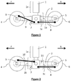
Figure 1 shows an arrangement for aircraft main landing gear according to a first embodiment of the present disclosure; -
Figure 2 shows an arrangement for aircraft main landing gear according to a second embodiment of the present disclosure; -
Figure 3 shows an arrangement for aircraft main landing gear according to a third embodiment of the present disclosure; and -
Figure 4 shows an arrangement for aircraft main landing gear according to a fourth embodiment of the present disclosure. - Current conventional multi-axle main landing gear configurations typically react brake torque (during landing) back to the structure, most often to the lower piston fork, either directly via shear pins (e.g., center axle brakes on 3 axle/6 wheel bogies) or indirectly via brake rods for the farthest axles (e.g., usually the fore and aft axles). The piston fork is the part of the landing gear at the base of the piston which extends to a bogie beam to provide an attachment portion for the bogie beam (herein referred to also as "attachment portion"). The brake rods act as structural members that transfer the resulting brake torques into simple tensile (aft brake rod) or compressive loads (forward brake rod) into the piston fork under braking conditions. Most commonly these brake rod connections are placed at the bottom of the piston fork generally being parallel to the bogie beam. This arrangement is efficient structurally for the aft brake rod (tensile loads) but is not so efficient for the forward brake rod (compressive loads).
- In a main landing gear according to a first embodiment of the disclosure, as shown in
Figure 1 , ashock strut 1 connects generally orthogonally to a central portion of abogie beam 2. Connected to oneend 3 of thebogie beam 2 is an axle of aforward wheel 4 and connected to theother end 5 of thebogie beam 2 is an axle of arear wheel 6. Thewheels bogie beam 2. - The words "forward" and "rear" in describing the
respective wheels - Figures correspond to the forward and rearward directions of the aircraft. Similar considerations apply where the terms "fore" and "aft" are used. References to "braking" herein are to be interpreted as references to braking during landing of the aircraft.
- The
shock strut 1 comprises acylinder 1 a and apiston 1 b having anattachment portion 1 c (piston fork) for pivotally holding thebogie beam 2 at a central point along the bogie beam. Theattachment portion 1 c has abase portion 7 usually in the form of a lug which protrudes below thebogie beam 2 when the landing gear is deployed, such that a horizontal line extending through thebase portion 7 when the aircraft is on the ground would pass vertically below the axes of thewheels - A
first brake rod 8, the rear brake rod, which is connected to thebase portion 7 of the piston'sattachment portion 1c, extends horizontally from thebase portion 7 towards therear wheel 6 and is for reacting torque in the rear braking assembly (shown in dotted line) during braking. When braking occurs thebrake rod 8 will experience a tensile force since the torque resulting from the braking (an anticlockwise torque on the rear brake assembly ofFigure 1 ) is reacted into thebase portion 7 via thebrake rod 8 inducing tension in an axial direction of therear brake rod 8. - A
second brake rod 9, the forward brake rod, which is connected to thebase portion 7 extends diagonally upwards from thebase portion 7 towards theforward wheel 4 and is for reacting torque in the forward braking assembly (shown in dotted line) during braking. When braking occurs theforward brake rod 9 will experience a tensile force since the torque resulting from the braking (an anticlockwise torque on the forward brake assembly ofFigure 1 ) is reacted into thebase portion 7 via theforward brake rod 9 inducing tension in an axial direction of theforward brake rod 9. - As can be seen in
Figure 1 , thebrake rods attachment portion 1 c, and in particular for theFigure 1 embodiment, to abase portion 7 of thepiston 1 b. Thus these other ends of thebrake rods bogie beam 2 but are instead connected directly to a lower end of thepiston 1 b, in particular theattachment portion 1 c for thebogie beam 2, the piston fork, which is designed to carry significant loads already. Accordingly, the tensile forces carried by thebrake rods shock strut 1 directly. - The connection positions of the first and
second brake rods attachment portion 1 c, so that the tensile forces pull on a surface of thepiston 1 b closest to therespective wheel brake rod - The connection positions of the first and
second brake rods attachment portion 1c, so that the tensile forces pull on a portion of thepiston 1 b closer to the respective brake assembly andwheel brake rod - The
piston 1 b, or at least theattachment portion 1 c thereof, may be formed of a strong, load bearing metal, such as steel, titanium or aluminium, which can readily resist the applied loads without failure. - By arranging the
forward brake rod 9 to primarily react tensile loads, e.g., by ensuring the forward brake-rod-to-brake connection is above the axle axis of the forward wheel 4 (ideally at or around the 12 o'clock position, as opposed to the 6 o'clock position traditionally), theforward brake rod 9 can be optimized to take full advantage of the yield strength of theforward brake rod 9, as opposed to sizing theforward brake rod 9 for column buckling which is the case now. This is particularly appropriate for non-metallic material systems such as advanced composites where the strength of currently available intermediate modulus fibres may be approximately 30-45% stronger and 10% stiffer in tension (as compared to compression). - Thus there is additional synergy with incorporating fibre composite brake rods in the new arrangements, e.g., as shown in
Figures 1 and 2 . It allows the brake rods (particularly the forward brake rods, which now primarily react tensile loads) to be sized for tensile loads rather than compressive loads, which in turn can result in significant weight savings compared to the current conventional configurations. - According to a second embodiment of the disclosure as shown in
Figure 2 , the arrangement of the main landing gear is the same as inFigure 1 except for the connection position of the forward brake rod and so like reference numbers will not be described again here. - In the second embodiment, the
second brake rod 10, i.e., the forward brake rod, is connected higher up theattachment portion 1 c, e.g., to anupper portion 11 at a position above thebase portion 7 when the landing gear is deployed. A horizontal line passing through the point of connection would pass through or above the axes of thewheels second brake rod 10 extends towards theforward wheel 4, at an inclined angle which is less steep than the angle of thesecond brake rod 9 of the first embodiment. Depending on the relative connection heights on the forward brake assembly and theupper portion 11, thesecond brake rod 10 may be upwardly inclined towards the forward brake assembly as shown, may be generally level, or may slope slightly downwardly. - When braking occurs the
second brake rod 10 will experience a tensile force since the torque resulting from the braking (an anticlockwise torque on the forward brake assembly ofFigure 2 ) is reacted into theupper portion 11 via theforward brake rod 10 inducing tension in an axial direction of theforward brake rod 10. - Thus in these embodiments, both the first and
second brake rods forward brake rod - Further, in the second embodiment, the
second brake rod 10 can be made shorter than thesecond brake rod 9 of the first embodiment for the same wheel spacing. Accordingly, the second embodiment can provide greater material and weight savings than the first embodiment. - In both arrangements, the connections to the piston can be on a rear facing surface and a forward facing surface respectively for the first and second brake rods, in order to deliver the tensile loads to these portions of the shock strut directly while also allowing the brake rods to be made as short as possible.
- Further, in both arrangements, the connections to the piston can be viewed as being on a rear portion and a forward portion of a side-facing surface (with reference to the direction of travel) of the
attachment portion 1 c respectively for the first and second brake rods, in order to deliver the tensile loads to these portions of the shock strut directly while also allowing the brake rods to be shorter. - As can be seen in
Figures 3 and 4 , alternative arrangements are envisioned wherein the bogie comprises three wheels (or six wheels if arranged in pairs). In this case, the central torque assembly for thecentral wheel 20 can be mounted directly on theattachment portion 1c. Accordingly, the braking torque from thecentral wheel 20 may be directly reacted by thepiston 1 b of theshock strut 1, without the need for a connecting brake rod. - Any weight savings in aircraft can lead to improved fuel efficiency. Thus the weight savings which can be achieved through using fibre composite brake rods in combination with configurations where the forward brake rod is primarily reacting tensile loads, can result in significant fuel savings.
- In any of the above-described embodiments, the composite brake rods may be designed to have a lay-up where a significant proportion of the fibres (e.g., more than 40% of the fibres) are placed having an axial orientation. By "axial orientation", what is meant herein is having an angle of within ±25° of an axial direction of the rod. For example, the fibres may be wound such that they follow a helical path which generally extends in an axial direction, e.g., between 5 and 25 degrees to the axis of the brake rod, and in most cases between 8 and 15 degrees. For example, the axially orientated fibres may be orientated at an angle of about 10 degrees to the axial direction of the brake rod. Although truly axial fibres will carry axial tensile loads best and are envisaged as a possible solution, it is generally easier from manufacturing considerations to rotate a mandrel (with the lay-up) relative to a fibre source than to rotate the fibre source relative to the mandrel/lay-up, resulting in the axially orientated fibres following an inclined path of a helix as they extend from one end of the rod to the other. The lay-up may also include fibres arranged in various non-axial directions (e.g., ±26-90°), for example, to provide hoop strength and other reinforcement against buckling and/or other applied loads, to ensure a robust brake rod.
- The fibre used in the fibre composite material may consist of carbon fibre.
- While the new landing gear arrangement has been described as having a particular arrangement with respect to the figures, the present disclosure can be further modified, as will be understood to one skilled in the art, within the scope of the present disclosure as defined in the claims.
- According to another aspect of the disclosure, there is provided an aircraft landing gear comprising forward and rear brake rods, wherein the forward and rear brake rods are connected to forward and rear brake assemblies such that they act in tension under braking conditions, and wherein the forward brake rod at least comprises fibre composite materials.
- All optional features of the previously described aspects apply equally to this aspect. Accordingly, the front brake rod may comprise fibres placed with an axial orientation (within ±25° of the axial direction), the axially orientated fibres may be present in an amount exceeding 40%, optionally greater than 50%, and the fibres may consist of carbon fibres. Similarly the rear brake rod may also exhibit these features. The front brake rod may connect to an attachment portion of a piston forward of a bogie beam pivot, and the rear brake rod may connect to the attachment portion aft of the bogie beam pivot.
- Further embodiments of the disclosure will now be described according to the following numbered clauses.
- 1. An arrangement for aircraft landing gear comprising:
- forward and rear wheels having axles;
- forward and rear torque brake assemblies for the forward and rear wheels;
- a bogie beam connecting the forward and rear wheels;
- a shock strut comprising a piston connected to a central portion of the bogie beam, the piston comprising a bogie beam attachment portion having a base portion which protrudes below the bogie beam when the landing gear is deployed; and
- first and second brake rods,
- 2. An arrangement for aircraft landing gear as described in
clause 1, wherein the second brake rod extends diagonally upwards from bogie beam attachment portion of the piston to the forward torque brake assembly. - 3. An arrangement for aircraft landing gear as described in
clause 1, wherein the second brake rod is connected to the bogie beam attachment portion of the piston at a position above the base portion and wherein the second brake rod extends diagonally across from the bogie beam attachment portion of the piston to the forward wheel. - 4. An arrangement for aircraft landing gear as described in any preceding clause, wherein the brake rods are formed of a composite material.
- 5. A method of designing an aircraft landing gear arrangement, comprising:
- configuring an arrangement of brake rods where: a forward end of a forward brake rod connects to an upper portion of a forward brake assembly and a rear end of the forward brake rod connects to a bogie beam attachment portion of a piston; and a rear end of a rear brake rod connects to a lower portion of a rear brake assembly and a forward end of the rear brake rod connects to the bogie beam attachment portion of the piston;
- determining a maximum braking load to be applied to the forward and rear brake rods in tension; and
- selecting a fibre lay-up comprising axially orientated fibres (within ±25° of an axial direction) to meet the determined tensile requirements.
- 6. A method as described in
clause 5, wherein the forward brake rod is not designed to carry compressive braking loads during landing. - 7. A method as described in
clause
Claims (15)
- An arrangement for landing gear comprising:a piston having an attachment portion with a pivot connection for a bogie beam at a lower end;a bogie beam mounted to the attachment portion at the pivot connection, the bogie beam supporting forward and rear brake assemblies on forward and rear sides of the piston respectively;a forward brake rod connected to the forward brake assembly at a location for acting under tension during braking; anda rear brake rod connected to the rear brake assembly at a location for acting under tension during braking;characterised in that a rear end of the forward brake rod is connected to the attachment portion forward of the pivot connection of the bogie beam, and a forward end of the rear brake rod is connected to the attachment portion, at a position rearward of the pivot connection.
- An arrangement for landing gear as claimed in claim 1, wherein the forward brake rod has been formed of a fibre composite material comprising fibres placed with an axial orientation (within ±25° of an axial direction of the forward brake rod), wherein preferably the axially orientated fibres follow a helical path inclined at an angle of 5° or more to an axial direction of the forward brake rod, more preferably an angle of between 8 and 15°.
- An arrangement for landing gear as claimed in claim 2, wherein the rear brake rod has been formed of a fibre composite material comprising fibres placed with an axial orientation (within ±25° of an axial direction of the rear brake rod), wherein preferably the axially orientated fibres follow a helical path inclined at an angle of 5° or more to an axial direction of the rear brake rod, more preferably an angle of between 8 and 15°.
- An arrangement for landing gear as claimed in claim 1, 2 or 3, wherein the forward brake rod connects to the forward brake assembly at a position above an axis of rotation for the forward brake assembly.
- An arrangement for landing gear as claimed in claim 4, wherein the forward brake rod connects to the forward brake assembly at a position substantially at the top of the forward brake assembly within ±45° of a vertical extending upwardly from the axis of rotation for the forward brake assembly, preferably within ±15° of a normal extending upwardly from the axis of rotation for the forward brake assembly.
- An arrangement for landing gear as claimed in any preceding claim, wherein the rear brake rod connects to the rear brake assembly at a position below an axis of rotation for a rear brake assembly.
- An arrangement for landing gear as claimed in claim 6, wherein the rear brake rod connects to the rear brake assembly at a position substantially at the bottom of the rear brake assembly within ±45° of a normal extending downwardly from the axis of rotation for the rear brake assembly, preferably within ±15° of a normal extending downwardly from the axis of rotation for the rear brake assembly.
- An arrangement for landing gear as claimed in any preceding claim, wherein the forward brake rod and the rear brake rod connect to a base portion of the attachment portion protruding below the bogie beam.
- An arrangement for landing gear as claimed in any of claims 1 to 7, wherein the forward brake rod connects to an upper portion of the attachment portion and the rear brake rod connects to a base portion of the attachment portion.
- An arrangement for landing gear as claimed in any preceding claim, wherein the forward brake rod connects to a forward facing surface of the attachment portion and the rear brake rod connects to a rear facing surface of the attachment portion.
- An arrangement for landing gear as claimed in claim 10, wherein the brake rods connect to lugs on the attachment portion.
- A method of reacting torque from forward and rear brake assemblies on a landing gear bogie beam via forward and rear brake rods, the method comprising:reacting torque from the braking assemblies as tension along the forward and rear brake rods into an attachment portion of a piston, the attachment portion having a pivot connection for mounting the bogie beam which supports the brake assemblies;the method being characterised in that a rear end of the forward brake rod reacts the torque from the forward brake assembly into the attachment portion forward of the pivot connection with the bogie beam as a tensile force under braking conditions, andin that a forward end of the rear brake rod reacts the torque from the rear brake assembly into the attachment portion at a position to a rear of the pivot connection as a tensile force under braking conditions.
- A method of reacting torque as claimed in claim 12, wherein the method comprises using a forward brake rod formed from a fibre composite material having axially orientated fibres (within ±25° of an axial direction of the forward brake rod) to transmit tensile forces along the forward brake rod, wherein preferably the axially orientated fibres follow a helical path inclined at an angle of 5° or more to an axial direction of the forward brake rod, more preferably an angle of between 8 and 15°.
- A method of reacting torque as claimed in claim 13, wherein the method comprises using a rear brake rod formed from a fibre composite material having axially orientated fibres (within ±25° of an axial direction of the rear brake rod) to transmit tensile forces along the rear brake rod, wherein preferably the axially orientated fibres follow a helical path inclined at an angle of 5° or more to an axial direction of the rear brake rod, more preferably an angle of between 8 and 15°.
- A method of reacting torque as claimed in any of claims 12 to 14, wherein the method comprises connecting a forward end of the forward brake rod to the forward brake assembly at a position above an axis of rotation for the forward brake assembly, and connecting a rear end of the forward brake rod to the attachment portion at a position above the pivot connection for the bogie beam.
Priority Applications (2)
| Application Number | Priority Date | Filing Date | Title |
|---|---|---|---|
| EP16179008.4A EP3269637B1 (en) | 2016-07-12 | 2016-07-12 | Landing gear arrangement |
| US15/643,283 US10526075B2 (en) | 2016-07-12 | 2017-07-06 | Landing gear arrangement |
Applications Claiming Priority (1)
| Application Number | Priority Date | Filing Date | Title |
|---|---|---|---|
| EP16179008.4A EP3269637B1 (en) | 2016-07-12 | 2016-07-12 | Landing gear arrangement |
Publications (2)
| Publication Number | Publication Date |
|---|---|
| EP3269637A1 true EP3269637A1 (en) | 2018-01-17 |
| EP3269637B1 EP3269637B1 (en) | 2021-12-08 |
Family
ID=56411451
Family Applications (1)
| Application Number | Title | Priority Date | Filing Date |
|---|---|---|---|
| EP16179008.4A Active EP3269637B1 (en) | 2016-07-12 | 2016-07-12 | Landing gear arrangement |
Country Status (2)
| Country | Link |
|---|---|
| US (1) | US10526075B2 (en) |
| EP (1) | EP3269637B1 (en) |
Citations (8)
| Publication number | Priority date | Publication date | Assignee | Title |
|---|---|---|---|---|
| US4043607A (en) * | 1975-02-07 | 1977-08-23 | Societe Nationale Industrielle Aerospatiale | Method and device for controlling disc brakes |
| EP0099319A2 (en) * | 1982-07-12 | 1984-01-25 | Goodyear Aerospace Corporation | Torque readout sensor |
| US5806794A (en) | 1995-01-27 | 1998-09-15 | The B.F.Goodrich Company | Aircraft braking system with damped brake rod |
| WO2006094145A1 (en) * | 2005-03-02 | 2006-09-08 | Goodrich Corporation | Landing gear with articulated length extension mechanism |
| US20120256050A1 (en) | 2009-10-23 | 2012-10-11 | Matthew Hilliard | Bogie stop block |
| US20140084108A1 (en) | 2011-04-13 | 2014-03-27 | Messier-Dowty Limited | Aircraft landing gear |
| EP2993129A1 (en) * | 2014-09-04 | 2016-03-09 | Messier-Dowty Limited | Aircraft landing gear assembly |
| US20160107747A1 (en) | 2014-10-16 | 2016-04-21 | Messier-Dowty Limited | Aircraft landing gear assembly |
Family Cites Families (7)
| Publication number | Priority date | Publication date | Assignee | Title |
|---|---|---|---|---|
| US2471956A (en) | 1945-04-02 | 1949-05-31 | James W F Holl | Torque equalizing braking apparatus |
| US2533607A (en) * | 1947-06-05 | 1950-12-12 | Electro Hydraulics Ltd | Torque equallzing means for aircraft landing gear brakes |
| US5947414A (en) | 1994-03-17 | 1999-09-07 | The Boeing Company | Main landing gear having tilting of main gear pivot pins |
| US6149100A (en) | 1996-04-10 | 2000-11-21 | The Boeing Company | Aircraft landing gear having axle to brake plate integration |
| US5944147A (en) | 1996-06-28 | 1999-08-31 | Alliedsignal Inc. | Integrated aircraft wheel, brake and axle |
| US7578466B2 (en) * | 2006-01-06 | 2009-08-25 | The Boeing Company | Mechanism for reducing heat generation in a joint |
| GB2493675B (en) | 2011-04-13 | 2013-08-07 | Messier Dowty Ltd | Aircraft landing gear |
-
2016
- 2016-07-12 EP EP16179008.4A patent/EP3269637B1/en active Active
-
2017
- 2017-07-06 US US15/643,283 patent/US10526075B2/en active Active
Patent Citations (8)
| Publication number | Priority date | Publication date | Assignee | Title |
|---|---|---|---|---|
| US4043607A (en) * | 1975-02-07 | 1977-08-23 | Societe Nationale Industrielle Aerospatiale | Method and device for controlling disc brakes |
| EP0099319A2 (en) * | 1982-07-12 | 1984-01-25 | Goodyear Aerospace Corporation | Torque readout sensor |
| US5806794A (en) | 1995-01-27 | 1998-09-15 | The B.F.Goodrich Company | Aircraft braking system with damped brake rod |
| WO2006094145A1 (en) * | 2005-03-02 | 2006-09-08 | Goodrich Corporation | Landing gear with articulated length extension mechanism |
| US20120256050A1 (en) | 2009-10-23 | 2012-10-11 | Matthew Hilliard | Bogie stop block |
| US20140084108A1 (en) | 2011-04-13 | 2014-03-27 | Messier-Dowty Limited | Aircraft landing gear |
| EP2993129A1 (en) * | 2014-09-04 | 2016-03-09 | Messier-Dowty Limited | Aircraft landing gear assembly |
| US20160107747A1 (en) | 2014-10-16 | 2016-04-21 | Messier-Dowty Limited | Aircraft landing gear assembly |
Also Published As
| Publication number | Publication date |
|---|---|
| EP3269637B1 (en) | 2021-12-08 |
| US10526075B2 (en) | 2020-01-07 |
| US20180016001A1 (en) | 2018-01-18 |
Similar Documents
| Publication | Publication Date | Title |
|---|---|---|
| US5224669A (en) | Landing gear for an aerodyne, with arches in composite material | |
| US5860621A (en) | Helicopter landing gear with skids | |
| US5211359A (en) | Landing gear for aerodynes, with crosspieces in composite material | |
| EP2277774B1 (en) | Retractable articulated landing gear | |
| US6948683B2 (en) | Aircraft landing gear | |
| CN100548798C (en) | The skid alighting gear of autogiro and the autogiro that comprises alighting gear like this | |
| EP3722205B1 (en) | Aircraft landing gear assembly | |
| EP2697115B1 (en) | Aircraft landing gear | |
| US8541091B2 (en) | Composite leg for landing gear assembly | |
| US8561945B2 (en) | Skid-type landing gear for a helicopter | |
| EP0067208A1 (en) | Combined beam support for landing gear. | |
| US20210253228A1 (en) | Modular landing gear | |
| CN208198032U (en) | Rear suspension for vehicle and vehicle with same | |
| EP3269637B1 (en) | Landing gear arrangement | |
| EP3009348B1 (en) | Aircraft landing gear assembly | |
| EP4269237A1 (en) | A rotary wing aircraft with an at least partially non-retractable landing gear | |
| CN211942851U (en) | Integrated assembly of half-axle sleeve and right suspension arm of front axle of vehicle and vehicle with integrated assembly | |
| EP2500232B1 (en) | Weight reduced running gear frame for a rail vehicle | |
| US20170259910A1 (en) | Landing Gear for a Light Aircraft, Comprising at Least Two Wheels | |
| EP3279084B1 (en) | Aircraft landing gear assembly | |
| CN104843072A (en) | Bionic vehicle frame | |
| CN104843075A (en) | Bionic crossbar-free semi-trailer frame | |
| EP4139208B1 (en) | Staggered wheel landing gear truck beam | |
| JP2010095130A (en) | Connecting rod | |
| CN121697740A (en) | Rear overhang structure and vehicle |
Legal Events
| Date | Code | Title | Description |
|---|---|---|---|
| PUAI | Public reference made under article 153(3) epc to a published international application that has entered the european phase |
Free format text: ORIGINAL CODE: 0009012 |
|
| STAA | Information on the status of an ep patent application or granted ep patent |
Free format text: STATUS: THE APPLICATION HAS BEEN PUBLISHED |
|
| AK | Designated contracting states |
Kind code of ref document: A1 Designated state(s): AL AT BE BG CH CY CZ DE DK EE ES FI FR GB GR HR HU IE IS IT LI LT LU LV MC MK MT NL NO PL PT RO RS SE SI SK SM TR |
|
| AX | Request for extension of the european patent |
Extension state: BA ME |
|
| STAA | Information on the status of an ep patent application or granted ep patent |
Free format text: STATUS: REQUEST FOR EXAMINATION WAS MADE |
|
| 17P | Request for examination filed |
Effective date: 20180717 |
|
| RBV | Designated contracting states (corrected) |
Designated state(s): AL AT BE BG CH CY CZ DE DK EE ES FI FR GB GR HR HU IE IS IT LI LT LU LV MC MK MT NL NO PL PT RO RS SE SI SK SM TR |
|
| GRAP | Despatch of communication of intention to grant a patent |
Free format text: ORIGINAL CODE: EPIDOSNIGR1 |
|
| STAA | Information on the status of an ep patent application or granted ep patent |
Free format text: STATUS: GRANT OF PATENT IS INTENDED |
|
| INTG | Intention to grant announced |
Effective date: 20210702 |
|
| GRAS | Grant fee paid |
Free format text: ORIGINAL CODE: EPIDOSNIGR3 |
|
| GRAA | (expected) grant |
Free format text: ORIGINAL CODE: 0009210 |
|
| STAA | Information on the status of an ep patent application or granted ep patent |
Free format text: STATUS: THE PATENT HAS BEEN GRANTED |
|
| AK | Designated contracting states |
Kind code of ref document: B1 Designated state(s): AL AT BE BG CH CY CZ DE DK EE ES FI FR GB GR HR HU IE IS IT LI LT LU LV MC MK MT NL NO PL PT RO RS SE SI SK SM TR |
|
| REG | Reference to a national code |
Ref country code: GB Ref legal event code: FG4D |
|
| REG | Reference to a national code |
Ref country code: AT Ref legal event code: REF Ref document number: 1453590 Country of ref document: AT Kind code of ref document: T Effective date: 20211215 Ref country code: CH Ref legal event code: EP |
|
| REG | Reference to a national code |
Ref country code: DE Ref legal event code: R096 Ref document number: 602016067070 Country of ref document: DE |
|
| REG | Reference to a national code |
Ref country code: IE Ref legal event code: FG4D |
|
| REG | Reference to a national code |
Ref country code: LT Ref legal event code: MG9D |
|
| REG | Reference to a national code |
Ref country code: NL Ref legal event code: MP Effective date: 20211208 |
|
| PG25 | Lapsed in a contracting state [announced via postgrant information from national office to epo] |
Ref country code: RS Free format text: LAPSE BECAUSE OF FAILURE TO SUBMIT A TRANSLATION OF THE DESCRIPTION OR TO PAY THE FEE WITHIN THE PRESCRIBED TIME-LIMIT Effective date: 20211208 Ref country code: LT Free format text: LAPSE BECAUSE OF FAILURE TO SUBMIT A TRANSLATION OF THE DESCRIPTION OR TO PAY THE FEE WITHIN THE PRESCRIBED TIME-LIMIT Effective date: 20211208 Ref country code: FI Free format text: LAPSE BECAUSE OF FAILURE TO SUBMIT A TRANSLATION OF THE DESCRIPTION OR TO PAY THE FEE WITHIN THE PRESCRIBED TIME-LIMIT Effective date: 20211208 Ref country code: BG Free format text: LAPSE BECAUSE OF FAILURE TO SUBMIT A TRANSLATION OF THE DESCRIPTION OR TO PAY THE FEE WITHIN THE PRESCRIBED TIME-LIMIT Effective date: 20220308 |
|
| REG | Reference to a national code |
Ref country code: AT Ref legal event code: MK05 Ref document number: 1453590 Country of ref document: AT Kind code of ref document: T Effective date: 20211208 |
|
| PG25 | Lapsed in a contracting state [announced via postgrant information from national office to epo] |
Ref country code: SE Free format text: LAPSE BECAUSE OF FAILURE TO SUBMIT A TRANSLATION OF THE DESCRIPTION OR TO PAY THE FEE WITHIN THE PRESCRIBED TIME-LIMIT Effective date: 20211208 Ref country code: NO Free format text: LAPSE BECAUSE OF FAILURE TO SUBMIT A TRANSLATION OF THE DESCRIPTION OR TO PAY THE FEE WITHIN THE PRESCRIBED TIME-LIMIT Effective date: 20220308 Ref country code: LV Free format text: LAPSE BECAUSE OF FAILURE TO SUBMIT A TRANSLATION OF THE DESCRIPTION OR TO PAY THE FEE WITHIN THE PRESCRIBED TIME-LIMIT Effective date: 20211208 Ref country code: HR Free format text: LAPSE BECAUSE OF FAILURE TO SUBMIT A TRANSLATION OF THE DESCRIPTION OR TO PAY THE FEE WITHIN THE PRESCRIBED TIME-LIMIT Effective date: 20211208 Ref country code: GR Free format text: LAPSE BECAUSE OF FAILURE TO SUBMIT A TRANSLATION OF THE DESCRIPTION OR TO PAY THE FEE WITHIN THE PRESCRIBED TIME-LIMIT Effective date: 20220309 Ref country code: ES Free format text: LAPSE BECAUSE OF FAILURE TO SUBMIT A TRANSLATION OF THE DESCRIPTION OR TO PAY THE FEE WITHIN THE PRESCRIBED TIME-LIMIT Effective date: 20211208 |
|
| PG25 | Lapsed in a contracting state [announced via postgrant information from national office to epo] |
Ref country code: NL Free format text: LAPSE BECAUSE OF FAILURE TO SUBMIT A TRANSLATION OF THE DESCRIPTION OR TO PAY THE FEE WITHIN THE PRESCRIBED TIME-LIMIT Effective date: 20211208 |
|
| PG25 | Lapsed in a contracting state [announced via postgrant information from national office to epo] |
Ref country code: SM Free format text: LAPSE BECAUSE OF FAILURE TO SUBMIT A TRANSLATION OF THE DESCRIPTION OR TO PAY THE FEE WITHIN THE PRESCRIBED TIME-LIMIT Effective date: 20211208 Ref country code: SK Free format text: LAPSE BECAUSE OF FAILURE TO SUBMIT A TRANSLATION OF THE DESCRIPTION OR TO PAY THE FEE WITHIN THE PRESCRIBED TIME-LIMIT Effective date: 20211208 Ref country code: RO Free format text: LAPSE BECAUSE OF FAILURE TO SUBMIT A TRANSLATION OF THE DESCRIPTION OR TO PAY THE FEE WITHIN THE PRESCRIBED TIME-LIMIT Effective date: 20211208 Ref country code: PT Free format text: LAPSE BECAUSE OF FAILURE TO SUBMIT A TRANSLATION OF THE DESCRIPTION OR TO PAY THE FEE WITHIN THE PRESCRIBED TIME-LIMIT Effective date: 20220408 Ref country code: EE Free format text: LAPSE BECAUSE OF FAILURE TO SUBMIT A TRANSLATION OF THE DESCRIPTION OR TO PAY THE FEE WITHIN THE PRESCRIBED TIME-LIMIT Effective date: 20211208 Ref country code: CZ Free format text: LAPSE BECAUSE OF FAILURE TO SUBMIT A TRANSLATION OF THE DESCRIPTION OR TO PAY THE FEE WITHIN THE PRESCRIBED TIME-LIMIT Effective date: 20211208 |
|
| PG25 | Lapsed in a contracting state [announced via postgrant information from national office to epo] |
Ref country code: PL Free format text: LAPSE BECAUSE OF FAILURE TO SUBMIT A TRANSLATION OF THE DESCRIPTION OR TO PAY THE FEE WITHIN THE PRESCRIBED TIME-LIMIT Effective date: 20211208 Ref country code: AT Free format text: LAPSE BECAUSE OF FAILURE TO SUBMIT A TRANSLATION OF THE DESCRIPTION OR TO PAY THE FEE WITHIN THE PRESCRIBED TIME-LIMIT Effective date: 20211208 |
|
| REG | Reference to a national code |
Ref country code: DE Ref legal event code: R097 Ref document number: 602016067070 Country of ref document: DE |
|
| PG25 | Lapsed in a contracting state [announced via postgrant information from national office to epo] |
Ref country code: IS Free format text: LAPSE BECAUSE OF FAILURE TO SUBMIT A TRANSLATION OF THE DESCRIPTION OR TO PAY THE FEE WITHIN THE PRESCRIBED TIME-LIMIT Effective date: 20220408 |
|
| PLBE | No opposition filed within time limit |
Free format text: ORIGINAL CODE: 0009261 |
|
| STAA | Information on the status of an ep patent application or granted ep patent |
Free format text: STATUS: NO OPPOSITION FILED WITHIN TIME LIMIT |
|
| PG25 | Lapsed in a contracting state [announced via postgrant information from national office to epo] |
Ref country code: DK Free format text: LAPSE BECAUSE OF FAILURE TO SUBMIT A TRANSLATION OF THE DESCRIPTION OR TO PAY THE FEE WITHIN THE PRESCRIBED TIME-LIMIT Effective date: 20211208 Ref country code: AL Free format text: LAPSE BECAUSE OF FAILURE TO SUBMIT A TRANSLATION OF THE DESCRIPTION OR TO PAY THE FEE WITHIN THE PRESCRIBED TIME-LIMIT Effective date: 20211208 |
|
| 26N | No opposition filed |
Effective date: 20220909 |
|
| PG25 | Lapsed in a contracting state [announced via postgrant information from national office to epo] |
Ref country code: SI Free format text: LAPSE BECAUSE OF FAILURE TO SUBMIT A TRANSLATION OF THE DESCRIPTION OR TO PAY THE FEE WITHIN THE PRESCRIBED TIME-LIMIT Effective date: 20211208 |
|
| PG25 | Lapsed in a contracting state [announced via postgrant information from national office to epo] |
Ref country code: MC Free format text: LAPSE BECAUSE OF FAILURE TO SUBMIT A TRANSLATION OF THE DESCRIPTION OR TO PAY THE FEE WITHIN THE PRESCRIBED TIME-LIMIT Effective date: 20211208 |
|
| REG | Reference to a national code |
Ref country code: CH Ref legal event code: PL |
|
| GBPC | Gb: european patent ceased through non-payment of renewal fee |
Effective date: 20220712 |
|
| REG | Reference to a national code |
Ref country code: BE Ref legal event code: MM Effective date: 20220731 |
|
| PG25 | Lapsed in a contracting state [announced via postgrant information from national office to epo] |
Ref country code: LU Free format text: LAPSE BECAUSE OF NON-PAYMENT OF DUE FEES Effective date: 20220712 Ref country code: LI Free format text: LAPSE BECAUSE OF NON-PAYMENT OF DUE FEES Effective date: 20220731 Ref country code: CH Free format text: LAPSE BECAUSE OF NON-PAYMENT OF DUE FEES Effective date: 20220731 |
|
| PG25 | Lapsed in a contracting state [announced via postgrant information from national office to epo] |
Ref country code: IT Free format text: LAPSE BECAUSE OF FAILURE TO SUBMIT A TRANSLATION OF THE DESCRIPTION OR TO PAY THE FEE WITHIN THE PRESCRIBED TIME-LIMIT Effective date: 20211208 Ref country code: GB Free format text: LAPSE BECAUSE OF NON-PAYMENT OF DUE FEES Effective date: 20220712 Ref country code: BE Free format text: LAPSE BECAUSE OF NON-PAYMENT OF DUE FEES Effective date: 20220731 |
|
| P01 | Opt-out of the competence of the unified patent court (upc) registered |
Effective date: 20230522 |
|
| PG25 | Lapsed in a contracting state [announced via postgrant information from national office to epo] |
Ref country code: IE Free format text: LAPSE BECAUSE OF NON-PAYMENT OF DUE FEES Effective date: 20220712 |
|
| PG25 | Lapsed in a contracting state [announced via postgrant information from national office to epo] |
Ref country code: HU Free format text: LAPSE BECAUSE OF FAILURE TO SUBMIT A TRANSLATION OF THE DESCRIPTION OR TO PAY THE FEE WITHIN THE PRESCRIBED TIME-LIMIT; INVALID AB INITIO Effective date: 20160712 |
|
| PG25 | Lapsed in a contracting state [announced via postgrant information from national office to epo] |
Ref country code: MK Free format text: LAPSE BECAUSE OF FAILURE TO SUBMIT A TRANSLATION OF THE DESCRIPTION OR TO PAY THE FEE WITHIN THE PRESCRIBED TIME-LIMIT Effective date: 20211208 Ref country code: CY Free format text: LAPSE BECAUSE OF FAILURE TO SUBMIT A TRANSLATION OF THE DESCRIPTION OR TO PAY THE FEE WITHIN THE PRESCRIBED TIME-LIMIT Effective date: 20211208 |
|
| PG25 | Lapsed in a contracting state [announced via postgrant information from national office to epo] |
Ref country code: TR Free format text: LAPSE BECAUSE OF FAILURE TO SUBMIT A TRANSLATION OF THE DESCRIPTION OR TO PAY THE FEE WITHIN THE PRESCRIBED TIME-LIMIT Effective date: 20211208 |
|
| PG25 | Lapsed in a contracting state [announced via postgrant information from national office to epo] |
Ref country code: MT Free format text: LAPSE BECAUSE OF FAILURE TO SUBMIT A TRANSLATION OF THE DESCRIPTION OR TO PAY THE FEE WITHIN THE PRESCRIBED TIME-LIMIT Effective date: 20211208 |
|
| PGFP | Annual fee paid to national office [announced via postgrant information from national office to epo] |
Ref country code: FR Payment date: 20250620 Year of fee payment: 10 |
|
| PGFP | Annual fee paid to national office [announced via postgrant information from national office to epo] |
Ref country code: DE Payment date: 20250620 Year of fee payment: 10 |