EP3269569A1 - Method and apparatus for uniquely identifying tyres for wheels of vehicles as part of vehicle wheel maintenance processes - Google Patents
Method and apparatus for uniquely identifying tyres for wheels of vehicles as part of vehicle wheel maintenance processes Download PDFInfo
- Publication number
- EP3269569A1 EP3269569A1 EP17177921.8A EP17177921A EP3269569A1 EP 3269569 A1 EP3269569 A1 EP 3269569A1 EP 17177921 A EP17177921 A EP 17177921A EP 3269569 A1 EP3269569 A1 EP 3269569A1
- Authority
- EP
- European Patent Office
- Prior art keywords
- wheel
- tyre
- marking
- digital code
- side wall
- Prior art date
- Legal status (The legal status is an assumption and is not a legal conclusion. Google has not performed a legal analysis and makes no representation as to the accuracy of the status listed.)
- Granted
Links
Images


Classifications
-
- B—PERFORMING OPERATIONS; TRANSPORTING
- B60—VEHICLES IN GENERAL
- B60C—VEHICLE TYRES; TYRE INFLATION; TYRE CHANGING; CONNECTING VALVES TO INFLATABLE ELASTIC BODIES IN GENERAL; DEVICES OR ARRANGEMENTS RELATED TO TYRES
- B60C25/00—Apparatus or tools adapted for mounting, removing or inspecting tyres
- B60C25/01—Apparatus or tools adapted for mounting, removing or inspecting tyres for removing tyres from or mounting tyres on wheels
- B60C25/05—Machines
- B60C25/0548—Machines equipped with sensing means, e.g. for positioning, measuring or controlling
- B60C25/0554—Machines equipped with sensing means, e.g. for positioning, measuring or controlling optical, e.g. cameras
-
- B—PERFORMING OPERATIONS; TRANSPORTING
- B41—PRINTING; LINING MACHINES; TYPEWRITERS; STAMPS
- B41J—TYPEWRITERS; SELECTIVE PRINTING MECHANISMS, i.e. MECHANISMS PRINTING OTHERWISE THAN FROM A FORME; CORRECTION OF TYPOGRAPHICAL ERRORS
- B41J2/00—Typewriters or selective printing mechanisms characterised by the printing or marking process for which they are designed
- B41J2/435—Typewriters or selective printing mechanisms characterised by the printing or marking process for which they are designed characterised by selective application of radiation to a printing material or impression-transfer material
- B41J2/44—Typewriters or selective printing mechanisms characterised by the printing or marking process for which they are designed characterised by selective application of radiation to a printing material or impression-transfer material using single radiation source per colour, e.g. lighting beams or shutter arrangements
- B41J2/442—Typewriters or selective printing mechanisms characterised by the printing or marking process for which they are designed characterised by selective application of radiation to a printing material or impression-transfer material using single radiation source per colour, e.g. lighting beams or shutter arrangements using lasers
-
- B—PERFORMING OPERATIONS; TRANSPORTING
- B60—VEHICLES IN GENERAL
- B60C—VEHICLE TYRES; TYRE INFLATION; TYRE CHANGING; CONNECTING VALVES TO INFLATABLE ELASTIC BODIES IN GENERAL; DEVICES OR ARRANGEMENTS RELATED TO TYRES
- B60C13/00—Tyre sidewalls; Protecting, decorating, marking, or the like, thereof
- B60C13/001—Decorating, marking or the like
-
- G—PHYSICS
- G01—MEASURING; TESTING
- G01M—TESTING STATIC OR DYNAMIC BALANCE OF MACHINES OR STRUCTURES; TESTING OF STRUCTURES OR APPARATUS, NOT OTHERWISE PROVIDED FOR
- G01M1/00—Testing static or dynamic balance of machines or structures
- G01M1/02—Details of balancing machines or devices
- G01M1/04—Adaptation of bearing support assemblies for receiving the body to be tested
- G01M1/045—Adaptation of bearing support assemblies for receiving the body to be tested the body being a vehicle wheel
-
- G—PHYSICS
- G06—COMPUTING OR CALCULATING; COUNTING
- G06K—GRAPHICAL DATA READING; PRESENTATION OF DATA; RECORD CARRIERS; HANDLING RECORD CARRIERS
- G06K19/00—Record carriers for use with machines and with at least a part designed to carry digital markings
- G06K19/06—Record carriers for use with machines and with at least a part designed to carry digital markings characterised by the kind of the digital marking, e.g. shape, nature, code
- G06K19/06009—Record carriers for use with machines and with at least a part designed to carry digital markings characterised by the kind of the digital marking, e.g. shape, nature, code with optically detectable marking
- G06K19/06037—Record carriers for use with machines and with at least a part designed to carry digital markings characterised by the kind of the digital marking, e.g. shape, nature, code with optically detectable marking multi-dimensional coding
-
- G—PHYSICS
- G06—COMPUTING OR CALCULATING; COUNTING
- G06K—GRAPHICAL DATA READING; PRESENTATION OF DATA; RECORD CARRIERS; HANDLING RECORD CARRIERS
- G06K7/00—Methods or arrangements for sensing record carriers, e.g. for reading patterns
- G06K7/10—Methods or arrangements for sensing record carriers, e.g. for reading patterns by electromagnetic radiation, e.g. optical sensing; by corpuscular radiation
- G06K7/10544—Methods or arrangements for sensing record carriers, e.g. for reading patterns by electromagnetic radiation, e.g. optical sensing; by corpuscular radiation by scanning of the records by radiation in the optical part of the electromagnetic spectrum
- G06K7/10821—Methods or arrangements for sensing record carriers, e.g. for reading patterns by electromagnetic radiation, e.g. optical sensing; by corpuscular radiation by scanning of the records by radiation in the optical part of the electromagnetic spectrum further details of bar or optical code scanning devices
- G06K7/10861—Methods or arrangements for sensing record carriers, e.g. for reading patterns by electromagnetic radiation, e.g. optical sensing; by corpuscular radiation by scanning of the records by radiation in the optical part of the electromagnetic spectrum further details of bar or optical code scanning devices sensing of data fields affixed to objects or articles, e.g. coded labels
-
- G—PHYSICS
- G09—EDUCATION; CRYPTOGRAPHY; DISPLAY; ADVERTISING; SEALS
- G09F—DISPLAYING; ADVERTISING; SIGNS; LABELS OR NAME-PLATES; SEALS
- G09F3/00—Labels, tag tickets, or similar identification or indication means; Seals; Postage or like stamps
- G09F3/02—Forms or constructions
- G09F3/0297—Forms or constructions including a machine-readable marking, e.g. a bar code
-
- B—PERFORMING OPERATIONS; TRANSPORTING
- B29—WORKING OF PLASTICS; WORKING OF SUBSTANCES IN A PLASTIC STATE IN GENERAL
- B29D—PRODUCING PARTICULAR ARTICLES FROM PLASTICS OR FROM SUBSTANCES IN A PLASTIC STATE
- B29D30/00—Producing pneumatic or solid tyres or parts thereof
- B29D30/06—Pneumatic tyres or parts thereof (e.g. produced by casting, moulding, compression moulding, injection moulding, centrifugal casting)
- B29D30/72—Side-walls
- B29D2030/728—Decorating or marking the sidewalls after tyre vulcanization
-
- B—PERFORMING OPERATIONS; TRANSPORTING
- B60—VEHICLES IN GENERAL
- B60C—VEHICLE TYRES; TYRE INFLATION; TYRE CHANGING; CONNECTING VALVES TO INFLATABLE ELASTIC BODIES IN GENERAL; DEVICES OR ARRANGEMENTS RELATED TO TYRES
- B60C25/00—Apparatus or tools adapted for mounting, removing or inspecting tyres
- B60C25/01—Apparatus or tools adapted for mounting, removing or inspecting tyres for removing tyres from or mounting tyres on wheels
- B60C25/05—Machines
- B60C25/132—Machines for removing and mounting tyres
- B60C25/135—Machines for removing and mounting tyres having a tyre support or a tool, movable along wheel axis
- B60C25/138—Machines for removing and mounting tyres having a tyre support or a tool, movable along wheel axis with rotary motion of tool or tyre support
Definitions
- the present invention relates to a method for uniquely identifying tyres for wheels of vehicles as part of wheel maintenance operations and a vehicle wheel maintenance apparatus capable of implementing said method.
- the present invention falls within the realm of apparatus used by tyre fitters in auto repair garages, such as, for example, tyre removal machines, balancing machines, etc. More in general, the present invention has application whenever a tyre mounted on a respective rim needs to be handled (checked, inspected, replaced).
- Tyres for vehicle wheels exhibit, on one or both sides (as engraved and/or raised symbols applied on the elastomeric material), the manufacturer's trademark, numbers identifying the characteristics of the tyre itself (dimensions, load index and speed rating, etc.) and additional codes serving to indicate, for example, a certain type of certification, e.g. the DOT code, acronym of "Department of Transportation".
- the DOT code is composed of a reference symbol (DOT) and additional codes (groups of numbers and letters in sequence), which usually, but not necessarily, follow the DOT symbol, and serve to identify the tyre; for example, they serve to indicate the manufacturing plant, dimensions and type of tyre, and the date of manufacture thereof.
- DOT codes do not represent actual serial numbers for identifying the individual tyres; in reality, they contain information serving simply to identify the entire production lot the tyre belongs to in order to manage any recall campaigns that might be decided by the manufacturer.
- EP 2 020 594 illustrates a method and an apparatus for determining the geometrical dimensions of a vehicle wheel.
- the apparatus is a balancing machine provided with a light source and a detector configured to detect a light beam emitted by the source and reflected from an area of the wheel surface.
- the apparatus further comprises an evaluation device connected to the detector and capable of determining the position and geometrical shape of the wheel area by means of a single point triangulation.
- the evaluation device can be used, for example, to detect the shape of the rim, the width of the rim and the letters and numbers on the side wall of the tyre.
- Document EP 2 347 919 illustrates a method for mounting a tyre on a rim or demounting a tyre from a rim, wherein images of the wheel or the rim are created by a vision system and sent to a computer. The images are correlated with commands sent to a fitting or removal tool so as to define the position of the tool relative to the rim and guide the tool on the basis of this correlation.
- Document EP 0 604 819 A2 discloses a system for marking tyres by generating and printing a label that is subsequently transferred and made to adhere to the tyre.
- document EP 1 207 061 A2 illustrates a machine for the maintenance of tyres comprising a device capable of reading and identifying any markings present on the tyre.
- the Applicant has observed that, in garages where maintenance and/or preparation work is performed on vehicles, and in particular on the wheels thereof (tyre changes, wheel balancing, wheel alignment, etc.), there do not exist any systems integrated into the apparatus used (for example: tyre removal and balancing machines, vehicle lifts, etc.) capable of uniquely identifying the tyre through the use of any engraved and/or raised symbols applied on the elastomeric material of the tyre, and then transmitting the data thereof to the control system of the apparatus (and enabling, for example, an automatic correlation between the type of tyre and the adjustment parameters of the wheel maintenance process and/or to simplify storage of the tyres in a storeroom once they have been removed from the vehicle, etc.).
- tyre removal and balancing machines for example: tyre removal and balancing machines, vehicle lifts, etc.
- the Applicant has set itself the objective of providing a simple and reliable method for uniquely identifying tyres for vehicle wheels by creating suitable markings on the tyre surface corresponding to respective digital codes uniquely identifying the specific tyre on which maintenance operations are performed in garages, so as to make said operations - including those related to storage of the tyres upstream and/or downstream of the maintenance operations in the garage - more simple, effective, precise, rapid and customisable.
- the Applicant has also set itself the objective of providing a vehicle wheel maintenance apparatus, preferably used in garages where maintenance and/or preparation of the vehicles themselves takes place, which incorporates a device capable of suitably marking the tyre with a digital code uniquely identifying the latter, and of automatically sending the data contained in said code to the management system of the apparatus and/or of the garage.
- a vehicle wheel maintenance apparatus preferably used in garages where maintenance and/or preparation of the vehicles themselves takes place
- a device capable of suitably marking the tyre with a digital code uniquely identifying the latter, and of automatically sending the data contained in said code to the management system of the apparatus and/or of the garage.
- it is an object of the invention to provide an apparatus of such a type that is precise and reliable.
- It is also an object of the invention to provide a structurally simple and relatively inexpensive apparatus.
- It is moreover an object of the invention to provide an apparatus that is simple to manage and easy to maintain.
- the Applicant has found that these objectives and aims can be achieved by integrating, into a vehicle wheel maintenance apparatus, a marking system operatively active at least on one surface of one side wall of the tyre and configured to mark said side wall with a marking corresponding to a unique digital code.
- the marking applied on the side wall of the tyre can then be detected by an optical vision system capable of reading the digital code and storing it in a database, which can then be shared with any apparatus for wheel maintenance and/or with any computerised system.
- the present invention relates to a method for uniquely identifying tyres for wheels of vehicles as part of wheel maintenance processes, comprising the steps of:
- the present invention relates to an apparatus for vehicle wheel maintenance, comprising:
- the system for marking the side wall of the tyre can be of various types, e.g. mechanical, optical, etc.
- the marking system is of an optical type, even more preferably it is a laser marking system.
- the present invention relates to a process for the maintenance of vehicle wheels comprising the method for identifying tyres according to the present invention.
- the method for identifying tyres enables tyres to be uniquely marked in concomitance with the operations of maintenance thereof in a simple, reliable and rapid manner, ensuring that each marking corresponds to a unique digital code, specific for each tyre.
- This code can be read and recognised by a suitable optical vision system, in order to subsequently identify the tyre thus marked.
- the tyre identification data can then be transmitted to the control unit of the maintenance apparatus or to other computers integrated into or external to the apparatus itself.
- the apparatus according to the invention makes it possible to implement tyre identification while maintaining the structure of the overall apparatus relatively simple and compact.
- the apparatus according to the invention is thus also reliable and inexpensive in terms of purchase and maintenance costs.
- the support suitable for receiving and supporting a rim of a vehicle wheel is mounted rotatably on the base of the vehicle wheel maintenance apparatus.
- the apparatus comprises a motor operatively connected to the rotatable support and configured to rotate said rotatable support and the wheel about a main axis of said wheel.
- control unit is further configured to control the motor so that it rotates the rotatable support and the wheel.
- the wheel is made to turn manually by an operator.
- the wheel is set into rotation about a main axis thereof whilst said marking is created on the side wall of the tyre.
- the wheel is stationary, i.e. it does not turn, whilst said marking is created on the side wall of the tyre.
- the marking comprises at least a first portion of surface having a first optical reflectivity and at least a second portion of surface having a second optical reflectivity, said first optical reflectivity being different from the second optical reflectivity.
- the marking comprises a plurality of engravings or recesses on the surface of the side wall of the tyre.
- the digital code is of the two-dimensional type; preferably it is a QR code.
- the digital code in addition to uniquely identifying the tyre, further comprises at least one piece of information relating to the wheel maintenance process and/or the rim on which said tyre is mounted.
- the digital code can comprise information about the type of process just carried out (mounting, removal, balancing, etc.), as well as on some characteristic parameters of the process itself.
- the digital code can also comprise information as to the date when the tyre and/or the wheel on which said tyre is mounted underwent the maintenance process. Furthermore, the digital code can also comprise information about the state of wear of the tyre and/or of the rim on which it is (or was) mounted, about the customer, etc.
- the digital code can also comprise further information, such as the name of the operator who performs the maintenance, the name and/or logo of the garage entrusted with performing the maintenance operation, and/or the name and/or logo of the distributor and/or manufacturer of the vehicle wheel maintenance apparatus.
- the digital code for uniquely identifying the tyre is automatically created by the control unit of the vehicle wheel maintenance apparatus.
- the digital code for uniquely identifying the tyre is created by the control unit of the vehicle wheel maintenance apparatus, based, however, on instructions sent to said control unit by an operator, who, optionally, can freely decide which type of coding to use, the possible structure and syntax thereof, and at least part or all of the contents of the information contained in the digital code.
- the information included in the digital code in addition to the information serving to uniquely identify the tyre, can also be automatically determined by the vehicle wheel maintenance apparatus.
- the information included in the digital code in addition to the information serving to uniquely identify the tyre, can instead be manually entered, partly or totally, by an operator.
- the optical vision system is capable of reading the marking on the surface of the side wall of the tyre and of recognising the corresponding digital code.
- the optical vision system is mounted fixed to the vehicle wheel maintenance apparatus.
- the optical vision system can comprise any type of image sensor, for example a camera, an optical sensor of the CCD or CMOS type, etc.
- the marking system and the optical vision system are integrated in a same optical marking and vision system.
- the optical vision system is instead separate from the wheel maintenance apparatus and is included in a portable device, for example a smartphone or a tablet.
- the portable device incorporating the optical vision system is capable of communicating, for example in a wireless mode, with the control unit of the vehicle wheel maintenance apparatus, and/or with a remote computerised system.
- control unit of the vehicle wheel maintenance apparatus is configured to control the optical vision system so as to read the marking on the surface of the side wall of the tyre.
- control unit is configured to recognise the digital code corresponding to the marking.
- the optical vision system is capable of recognising the digital code corresponding to the marking, and of communicating this information to the control unit.
- control unit and/or the optical vision system are capable of communicating with a local or remote database in which the digital codes corresponding to an equal number of tyres are stored.
- the database containing the digital codes is populated upon the creation thereof.
- the database containing the digital codes is populated upon the reading thereof on the side wall of the tyres.
- the database can contain both information related to the digital codes as created, for example by the control unit, and as actually read by the vision system.
- the digital codes that may already be present in the database are compared with those obtained by the vision system, in order to verify the correspondence thereof.
- control unit and/or the optical vision system is capable of sharing at least one portion of said database with any vehicle maintenance apparatus, for example with the apparatus on which the wheel undergoing the maintenance operation is mounted, or with other apparatus present locally in the same garage or also in a remote location.
- control unit and/or the optical vision system is capable of sharing at least one portion of said database with any computerised system, for example locally located in the apparatus that is performing the maintenance operation on the wheel to be treated, or else also remote, for example a computerised system for managing a plurality of wheel maintenance apparatus, a storeroom for the storage of tyres, a list of customers and/or suppliers, etc.
- any computerised system for example locally located in the apparatus that is performing the maintenance operation on the wheel to be treated, or else also remote, for example a computerised system for managing a plurality of wheel maintenance apparatus, a storeroom for the storage of tyres, a list of customers and/or suppliers, etc.
- the at least one portion of database can be shared in a wired or wireless mode.
- the apparatus is a device for mounting tyres on a rim and/or demounting tyres from a rim.
- the apparatus is a wheel balancer.
- the apparatus is a tyre removal machine.
- the process comprises: balancing the wheel.
- the process comprises: mounting a tyre on a rim and/or removing a tyre from a rim
- the apparatus is a vehicle lift.
- the process comprises: determining the alignment of at least one wheel of the vehicle.
- 1 denotes in its entirety a vehicle wheel maintenance apparatus.
- the apparatus 1 illustrated in figure 1 is a device for mounting tyres 2 on a rim 3 of a wheel 4 and/or demounting tyres 2 from a rim 3.
- the apparatus 1 comprises a base 5 intended to rest on the ground.
- a rotatable support 6 defined by a vertical shaft, at the upper end of which there is disposed a support means, not illustrated in detail and known per se, such as, for example, a support plate intended to receive and support the rim 3 of the wheel 2, and a locking means, not illustrated in detail and known per se, which enables the rim 3 to be solidly constrained to the shaft 6.
- the shaft 6 is rotatable on the base 5 about a main axis A thereof and is connected to an electric motor, for example inside a casing of the base 5 and not illustrated.
- the motor is configured to rotate the shaft 6 and the wheel 4 together about the main axis A of the shaft 6 (which coincides with the main or rotation axis of the wheel 4).
- the base 5 comprises a column 7 that extends vertically.
- the column 7 is substantially parallel to the shaft 6 and carries at least one mounting and removal tool 8, known per se and not described in detail, suitable for removing and mounting a tyre 2 from/on the rim 3.
- the mounting and removal tool 8 is configured to come into contact with the sides of the tyre 2 from below and/or above in proximity to the beads of the tyre 2 which, when said tyre 2 is mounted on the rim 3, lie behind two containing flanges belonging to the rim 3 itself.
- An actuator is operatively connected to the mounting and removal tool 8 and is connected to a control unit 9 of the apparatus 1.
- the control unit 9 is configured to send command signals to the actuator so as to control the mounting and removal tool 8 in order to demount or mount a tyre 2 from/on the rim 3.
- This operation is managed by an operator via a user interface (comprising, for example, buttons, pedals, touch screens, etc.) connected to the control unit and not illustrated.
- the apparatus 1 further comprises a laser marking system 10, connected to the control unit 9, to generate a plurality of engravings on the side wall 2A of the tyre 2.
- a laser marking system 10 is mounted on an arm 12 projecting from the column 7 above the wheel 4 when the latter is mounted on a support means.
- the laser marking system 10 is aimed downwards so as to frame an area of the surface of the upper side wall 2A of the tyre 2.
- the laser marking system 10 can be moved along the longitudinal direction F2 of the arm 12, so as to be able to operate on a tyre 2 of any type and size.
- the arm 12 is preferably supported by a carriage 20 movable parallel to the column 7, along the direction F1.
- the laser marking system 10 can also be moved in turn relative to the base 5, so as to be able to come sufficiently close to the side wall 2A of the tyre 2 during the marking step, and be moved away once the marking has been performed so as not to be a hindrance for the subsequent maintenance operations the wheel 4 undergoes.
- Both movements along the directions F1 and F2 can take place manually through the direct intervention of an operator, or else automatically; for example, they can be controlled by the control unit 9, which can be configured to receive input data regarding the dimensions of the wheel and/or tyre and/or the step of the wheel maintenance process it is desired to implement, and adjust, accordingly, the position of the laser marking system 10 along both directions F1 and F2, or also relative to only one of them (in the latter case the position of the laser marking system 10 along the remaining direction will be manually adjusted by the operator).
- the laser marking system 10 generally also comprises a screen 11 to adequately protect the operator and evacuate fumes, vapours or residues generated by the engraving process.
- the laser marking system 10 is capable of operating only on the upper side wall 2A of the tyre.
- the laser marking system 10 can be alternatively mounted so as to be able to operate on the lower side wall 2A of the tyre 2, just as it is possible to envisage the use of two laser marking systems 10, one capable of operating on the upper side wall 2A and one capable of operating on the lower side wall 2A of the tyre 2.
- a special movement and support means capable of positioning a single laser marking system 10 both above and below the tyre 2.
- the single laser marking system 10 that the apparatus 1 would be endowed with could in any case be capable of operating on both sides 2A, 2B of the tyre 2.
- the laser marking system 10 is operatively connected to the control unit 9 which controls the mounting and demounting tool 8, as in the example illustrated, or to a different control unit, not illustrated.
- the control unit 9 is capable of creating a digital code for uniquely identifying the tyre 2, preferably a two-dimensional code.
- the two-dimensional digital code is represented as a QR code (acronym for "Quick Response").
- This code can be automatically or semi-automatically created by the control unit, or else it can be manually entered by an operator, for example through a specific input means such as a keyboard, a touch screen, etc. (not illustrated).
- the digital code is then transmitted by the control unit to the laser marking system 10, in order to be subsequently engraved in the form of a marking on the side wall of the tyre.
- Said marking preferably comprises at least a first portion of surface having a first optical reflectivity and at least a second portion of surface having a second optical reflectivity, said first optical reflectivity being different from the second optical reflectivity.
- the wheel 4, complete with the rim 3 and tyre 2 is mounted on the support 6.
- the control unit 9 Before the tyre 2 is demounted from the rim 3 or after the tyre 2 has been mounted on the rim 3, by means of the mounting and removal tool 8 and in a manner known per se, the control unit 9 generates a digital code for uniquely identifying the tyre 2.
- This digital code is communicated to the laser marking system 10, which, movable along the directions F1 and F2, is positioned by an operator, or is positioned automatically if suitably controlled by the control unit 9 via a suitable actuator means known per se and not illustrated, from a rest position, wherein said laser marking system 10 is away from the tyre to be marked, into an operative position sufficiently close to the tyre 2 so as to be able to perform said marking.
- the marking is then engraved, by means of the laser light source, on the surface of the side wall of the tyre in the form of a plurality of engravings or recesses, representing at least one QR code.
- QR codes engraved on the side wall of the tyres can later be read by an optical vision system, comprising at least one camera and suitable recognition software.
- optical vision system comprising at least one camera and suitable recognition software.
- SCANNECT developed by the company 4JET Technologies GmbH.
- Said optical vision system can be directly mounted on the apparatus 1 (solution not illustrated in the figures) or, alternatively, it can be compressed in a portable device, for example in a common smartphone or tablet.
- the codes read are then sent, for example, to management software operating on a remote computer and used to manage the storeroom of a garage.
- control unit 9 the control unit 9:
- the vision system is optionally capable of:
- This third step of the method according to the invention can be performed by the vision system on its own or in cooperation between the vision system and the control unit of the wheel maintenance apparatus, both in the event that the vision system is integrated into the apparatus itself and in the event that it is incorporated in a portable device like a smartphone or tablet.
- control unit of the vehicle wheel maintenance apparatus which may be connected to the vision system, but not necessarily, is finally optionally capable of:
- the fourth and last step of the method indicated above can be equally well performed by the control unit of the wheel maintenance apparatus or by the portable device (smartphone, tablet), or by a local and/or remote computerised system, separately and/or in cooperation with one another.
- the database containing the digital codes can also be initially populated at the time of creation of the same, or prior to the marking and/or reading steps.
- the reading step will serve to retrieve codes that will preferably then be compared with those previously stored in the database, in order to verify the exact correspondence thereof.
- the apparatus 1 illustrated in figure 2 is a wheel balancing machine 4.
- the same reference numbers have been used for the elements of the balancing machine 1 corresponding to those present in the tyre mounting/demounting device 2.
- the balancing machine 1 comprises a base 5 intended to rest on the ground. Mounted on the base 5 there is a rotatable support 6 defined by a horizontal shaft, at the ends of which there are disposed support means, not illustrated in detail and known per se, intended to receive and support the rim 3 of the wheel 2, and a locking means, not illustrated in detail and known per se, which enables the rim 3 to be solidly constrained to the shaft 6.
- the shaft 6 is rotatable on the base 5 about a main axis A thereof and is connected to an electric motor, for example inside a casing of the base 5 and not illustrated.
- the motor is configured to rotate the shaft 6 and the wheel 4 together about the main axis "A" of the shaft 6 (which coincides with the main or rotation axis of the wheel 4).
- the balancing machine comprises devices, known per se and neither described nor illustrated, suitable for enabling the static and/or dynamic balancing of the wheel while the latter rotates about the main axis A.
- the apparatus 1 further comprises a control unit 9 and a laser marking system 10, connected to said control unit 9.
- the laser marking system 10 is positioned in such a way as to be able to operate on the right side wall 2A of the tyre 2.
- the laser marking system 10 in such a way that it can operate on the left side wall 2A of the tyre, or it is possible to use a movement and support means, not illustrated, capable of positioning a single laser marking system 10 either on the right or left relative to the tyre 2, so as to be able to operate on both of the side walls 2A, 2B.
- a movement and support means capable of positioning a single laser marking system 10 either on the right or left relative to the tyre 2, so as to be able to operate on both of the side walls 2A, 2B.
- the position of the laser marking system 10 is further adjustable along the directions F1 and F2, automatically or manually.
- the structure and functioning of the laser marking system 10 when the wheel maintenance apparatus is a balancing machine, are wholly analogous to what was described above for the case in which said apparatus is a tyre mounting/demounting device, and will thus not be repeated here.
Landscapes
- Physics & Mathematics (AREA)
- Engineering & Computer Science (AREA)
- General Physics & Mathematics (AREA)
- Theoretical Computer Science (AREA)
- Electromagnetism (AREA)
- Mechanical Engineering (AREA)
- Computer Vision & Pattern Recognition (AREA)
- Artificial Intelligence (AREA)
- Toxicology (AREA)
- General Health & Medical Sciences (AREA)
- Health & Medical Sciences (AREA)
- Optics & Photonics (AREA)
- Management, Administration, Business Operations System, And Electronic Commerce (AREA)
- Vehicle Cleaning, Maintenance, Repair, Refitting, And Outriggers (AREA)
- Tires In General (AREA)
- Manufacturing & Machinery (AREA)
- Measuring Fluid Pressure (AREA)
Abstract
Description
- The present invention relates to a method for uniquely identifying tyres for wheels of vehicles as part of wheel maintenance operations and a vehicle wheel maintenance apparatus capable of implementing said method. In particular, the present invention falls within the realm of apparatus used by tyre fitters in auto repair garages, such as, for example, tyre removal machines, balancing machines, etc. More in general, the present invention has application whenever a tyre mounted on a respective rim needs to be handled (checked, inspected, replaced).
- Tyres for vehicle wheels exhibit, on one or both sides (as engraved and/or raised symbols applied on the elastomeric material), the manufacturer's trademark, numbers identifying the characteristics of the tyre itself (dimensions, load index and speed rating, etc.) and additional codes serving to indicate, for example, a certain type of certification, e.g. the DOT code, acronym of "Department of Transportation". The DOT code is composed of a reference symbol (DOT) and additional codes (groups of numbers and letters in sequence), which usually, but not necessarily, follow the DOT symbol, and serve to identify the tyre; for example, they serve to indicate the manufacturing plant, dimensions and type of tyre, and the date of manufacture thereof.
- It is worth noting here that DOT codes do not represent actual serial numbers for identifying the individual tyres; in reality, they contain information serving simply to identify the entire production lot the tyre belongs to in order to manage any recall campaigns that might be decided by the manufacturer.
- There also exist complex and costly camera and 3D laser-based systems capable of capturing and recognising the aforesaid codes, which further require a very precise, specific positioning of the cameras in order to obtain the desired results. Also known is
document EP 2 020 594 , which illustrates a method and an apparatus for determining the geometrical dimensions of a vehicle wheel. The apparatus is a balancing machine provided with a light source and a detector configured to detect a light beam emitted by the source and reflected from an area of the wheel surface. The apparatus further comprises an evaluation device connected to the detector and capable of determining the position and geometrical shape of the wheel area by means of a single point triangulation. The evaluation device can be used, for example, to detect the shape of the rim, the width of the rim and the letters and numbers on the side wall of the tyre. -
Document EP 2 347 919 illustrates a method for mounting a tyre on a rim or demounting a tyre from a rim, wherein images of the wheel or the rim are created by a vision system and sent to a computer. The images are correlated with commands sent to a fitting or removal tool so as to define the position of the tool relative to the rim and guide the tool on the basis of this correlation. - Document
WO 2005/000714 A1 discloses a system for marking tyres using laser beams, in the context of a tyre manufacturing process. - Document
EP 0 604 819 A2 discloses a system for marking tyres by generating and printing a label that is subsequently transferred and made to adhere to the tyre. - Finally, document
EP 1 207 061 A2 illustrates a machine for the maintenance of tyres comprising a device capable of reading and identifying any markings present on the tyre. - The Applicant has observed that, in garages where maintenance and/or preparation work is performed on vehicles, and in particular on the wheels thereof (tyre changes, wheel balancing, wheel alignment, etc.), there do not exist any systems integrated into the apparatus used (for example: tyre removal and balancing machines, vehicle lifts, etc.) capable of uniquely identifying the tyre through the use of any engraved and/or raised symbols applied on the elastomeric material of the tyre, and then transmitting the data thereof to the control system of the apparatus (and enabling, for example, an automatic correlation between the type of tyre and the adjustment parameters of the wheel maintenance process and/or to simplify storage of the tyres in a storeroom once they have been removed from the vehicle, etc.).
- In this context, the Applicant has set itself the objective of providing a simple and reliable method for uniquely identifying tyres for vehicle wheels by creating suitable markings on the tyre surface corresponding to respective digital codes uniquely identifying the specific tyre on which maintenance operations are performed in garages, so as to make said operations - including those related to storage of the tyres upstream and/or downstream of the maintenance operations in the garage - more simple, effective, precise, rapid and customisable.
- The Applicant has also set itself the objective of providing a vehicle wheel maintenance apparatus, preferably used in garages where maintenance and/or preparation of the vehicles themselves takes place, which incorporates a device capable of suitably marking the tyre with a digital code uniquely identifying the latter, and of automatically sending the data contained in said code to the management system of the apparatus and/or of the garage. In particular, it is an object of the invention to provide an apparatus of such a type that is precise and reliable. It is also an object of the invention to provide a structurally simple and relatively inexpensive apparatus. It is moreover an object of the invention to provide an apparatus that is simple to manage and easy to maintain.
- The Applicant has found that these objectives and aims can be achieved by integrating, into a vehicle wheel maintenance apparatus, a marking system operatively active at least on one surface of one side wall of the tyre and configured to mark said side wall with a marking corresponding to a unique digital code. The marking applied on the side wall of the tyre can then be detected by an optical vision system capable of reading the digital code and storing it in a database, which can then be shared with any apparatus for wheel maintenance and/or with any computerised system.
- More specifically, in accordance with a first aspect, the present invention relates to a method for uniquely identifying tyres for wheels of vehicles as part of wheel maintenance processes, comprising the steps of:
- mounting a wheel for vehicles on a support of an apparatus for maintenance of vehicle wheels, said wheel comprising a rim and a tyre;
- creating a digital code for uniquely identifying said tyre;
- creating, using a marking system, preferably of the optical type, at least one marking on the surface of a side wall of the tyre of said wheel, corresponding to the digital code previously created.
- In accordance with a second aspect, the present invention relates to an apparatus for vehicle wheel maintenance, comprising:
- a base;
- a support mounted on the base and designed to receive and sustain a rim of a wheel of a vehicle;
- a marking system, preferably of the optical type, operatively active on a surface of at least one side wall of the tyre of said wheel, for marking said at least one side wall of the tyre;
- a control unit operatively connected to said marking system and designed for:
- creating a digital code for uniquely identifying said tyre;
- controlling the marking system so that it creates at least one marking on the surface of the side wall of the tyre of said wheel, corresponding to the digital code previously created.
- The system for marking the side wall of the tyre can be of various types, e.g. mechanical, optical, etc. Preferably, the marking system is of an optical type, even more preferably it is a laser marking system.
- In accordance with a third aspect, the present invention relates to a process for the maintenance of vehicle wheels comprising the method for identifying tyres according to the present invention.
- The method for identifying tyres according to the invention enables tyres to be uniquely marked in concomitance with the operations of maintenance thereof in a simple, reliable and rapid manner, ensuring that each marking corresponds to a unique digital code, specific for each tyre. This code can be read and recognised by a suitable optical vision system, in order to subsequently identify the tyre thus marked. The tyre identification data can then be transmitted to the control unit of the maintenance apparatus or to other computers integrated into or external to the apparatus itself.
- The apparatus according to the invention makes it possible to implement tyre identification while maintaining the structure of the overall apparatus relatively simple and compact. The apparatus according to the invention is thus also reliable and inexpensive in terms of purchase and maintenance costs.
- In one aspect, the support suitable for receiving and supporting a rim of a vehicle wheel is mounted rotatably on the base of the vehicle wheel maintenance apparatus.
- In one aspect, the apparatus comprises a motor operatively connected to the rotatable support and configured to rotate said rotatable support and the wheel about a main axis of said wheel.
- In one aspect, the control unit is further configured to control the motor so that it rotates the rotatable support and the wheel.
- In one aspect, the wheel is made to turn manually by an operator.
- In one aspect, the wheel is set into rotation about a main axis thereof whilst said marking is created on the side wall of the tyre.
- In one aspect, the wheel is stationary, i.e. it does not turn, whilst said marking is created on the side wall of the tyre.
- In one aspect, the marking comprises at least a first portion of surface having a first optical reflectivity and at least a second portion of surface having a second optical reflectivity, said first optical reflectivity being different from the second optical reflectivity.
- In one aspect, the marking comprises a plurality of engravings or recesses on the surface of the side wall of the tyre.
- In one aspect, the digital code is of the two-dimensional type; preferably it is a QR code.
- In one aspect, the digital code, in addition to uniquely identifying the tyre, further comprises at least one piece of information relating to the wheel maintenance process and/or the rim on which said tyre is mounted. For example, the digital code can comprise information about the type of process just carried out (mounting, removal, balancing, etc.), as well as on some characteristic parameters of the process itself.
- The digital code can also comprise information as to the date when the tyre and/or the wheel on which said tyre is mounted underwent the maintenance process. Furthermore, the digital code can also comprise information about the state of wear of the tyre and/or of the rim on which it is (or was) mounted, about the customer, etc.
- Optionally, the digital code can also comprise further information, such as the name of the operator who performs the maintenance, the name and/or logo of the garage entrusted with performing the maintenance operation, and/or the name and/or logo of the distributor and/or manufacturer of the vehicle wheel maintenance apparatus.
- In one aspect, the digital code for uniquely identifying the tyre is automatically created by the control unit of the vehicle wheel maintenance apparatus.
- In one aspect, the digital code for uniquely identifying the tyre is created by the control unit of the vehicle wheel maintenance apparatus, based, however, on instructions sent to said control unit by an operator, who, optionally, can freely decide which type of coding to use, the possible structure and syntax thereof, and at least part or all of the contents of the information contained in the digital code.
- In one aspect, the information included in the digital code, in addition to the information serving to uniquely identify the tyre, can also be automatically determined by the vehicle wheel maintenance apparatus.
- In a further aspect, the information included in the digital code, in addition to the information serving to uniquely identify the tyre, can instead be manually entered, partly or totally, by an operator.
- In one aspect, the optical vision system is capable of reading the marking on the surface of the side wall of the tyre and of recognising the corresponding digital code.
- In one aspect, the optical vision system is mounted fixed to the vehicle wheel maintenance apparatus. In this case, the optical vision system can comprise any type of image sensor, for example a camera, an optical sensor of the CCD or CMOS type, etc. Preferably, but not necessarily, when the vision system is mounted integral with the wheel maintenance apparatus, the marking system and the optical vision system are integrated in a same optical marking and vision system.
- In one aspect, the optical vision system is instead separate from the wheel maintenance apparatus and is included in a portable device, for example a smartphone or a tablet.
- In one aspect, the portable device incorporating the optical vision system is capable of communicating, for example in a wireless mode, with the control unit of the vehicle wheel maintenance apparatus, and/or with a remote computerised system.
- In one aspect, the control unit of the vehicle wheel maintenance apparatus is configured to control the optical vision system so as to read the marking on the surface of the side wall of the tyre.
- In one aspect, the control unit is configured to recognise the digital code corresponding to the marking.
- In one aspect, the optical vision system is capable of recognising the digital code corresponding to the marking, and of communicating this information to the control unit.
- In one aspect, the control unit and/or the optical vision system are capable of communicating with a local or remote database in which the digital codes corresponding to an equal number of tyres are stored.
- In one aspect, the database containing the digital codes is populated upon the creation thereof.
- In one aspect, the database containing the digital codes is populated upon the reading thereof on the side wall of the tyres.
- In one aspect, the database can contain both information related to the digital codes as created, for example by the control unit, and as actually read by the vision system.
- In one aspect, the digital codes that may already be present in the database are compared with those obtained by the vision system, in order to verify the correspondence thereof.
- In one aspect, the control unit and/or the optical vision system is capable of sharing at least one portion of said database with any vehicle maintenance apparatus, for example with the apparatus on which the wheel undergoing the maintenance operation is mounted, or with other apparatus present locally in the same garage or also in a remote location.
- In one aspect, the control unit and/or the optical vision system is capable of sharing at least one portion of said database with any computerised system, for example locally located in the apparatus that is performing the maintenance operation on the wheel to be treated, or else also remote, for example a computerised system for managing a plurality of wheel maintenance apparatus, a storeroom for the storage of tyres, a list of customers and/or suppliers, etc.
- In one aspect, the at least one portion of database can be shared in a wired or wireless mode.
- In a different aspect, the apparatus is a device for mounting tyres on a rim and/or demounting tyres from a rim.
- In one aspect, the apparatus is a wheel balancer.
- In one aspect, the apparatus is a tyre removal machine.
- In one aspect, the process comprises: balancing the wheel.
- In one aspect, the process comprises: mounting a tyre on a rim and/or removing a tyre from a rim
- In one aspect, the apparatus is a vehicle lift.
- In one aspect, the process comprises: determining the alignment of at least one wheel of the vehicle.
- Additional features and advantages will become more apparent from the detailed description of preferred, but non-exclusive embodiments of a method and apparatus for vehicle wheel maintenance in accordance with the present invention. This description will be given below with reference to the attached drawings, provided solely for illustrative and therefore non-limiting purposes, in which:
-
figure 1 shows a first embodiment of the apparatus according to the invention; -
figure 2 shows a second embodiment of the apparatus according to the invention; -
figure 3 illustrates a block diagram of a method for uniquely identifying tyres according to the invention; -
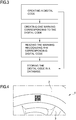
figure 4 illustrates a side wall of a tyre marked with a QR code. - In the description that follows, any expressions used, for example "right", "left", "above", "below", "upper", "lower" and the like, have a merely illustrative purpose and refer to the particular arrangement of the elements present in the appended figures, and do not, therefore, have any limiting character.
- With reference to the appended
figures, 1 denotes in its entirety a vehicle wheel maintenance apparatus. - The apparatus 1 illustrated in
figure 1 is a device for mountingtyres 2 on arim 3 of awheel 4 and/ordemounting tyres 2 from arim 3. The apparatus 1 comprises abase 5 intended to rest on the ground. Mounted on thebase 5 there is arotatable support 6 defined by a vertical shaft, at the upper end of which there is disposed a support means, not illustrated in detail and known per se, such as, for example, a support plate intended to receive and support therim 3 of thewheel 2, and a locking means, not illustrated in detail and known per se, which enables therim 3 to be solidly constrained to theshaft 6. Theshaft 6 is rotatable on thebase 5 about a main axis A thereof and is connected to an electric motor, for example inside a casing of thebase 5 and not illustrated. The motor is configured to rotate theshaft 6 and thewheel 4 together about the main axis A of the shaft 6 (which coincides with the main or rotation axis of the wheel 4). Thebase 5 comprises acolumn 7 that extends vertically. Thecolumn 7 is substantially parallel to theshaft 6 and carries at least one mounting andremoval tool 8, known per se and not described in detail, suitable for removing and mounting atyre 2 from/on therim 3. The mounting andremoval tool 8 is configured to come into contact with the sides of thetyre 2 from below and/or above in proximity to the beads of thetyre 2 which, when saidtyre 2 is mounted on therim 3, lie behind two containing flanges belonging to therim 3 itself. - An actuator, known per se and not illustrated, is operatively connected to the mounting and
removal tool 8 and is connected to acontrol unit 9 of the apparatus 1. Thecontrol unit 9 is configured to send command signals to the actuator so as to control the mounting andremoval tool 8 in order to demount or mount atyre 2 from/on therim 3. This operation is managed by an operator via a user interface (comprising, for example, buttons, pedals, touch screens, etc.) connected to the control unit and not illustrated. - The apparatus 1 further comprises a
laser marking system 10, connected to thecontrol unit 9, to generate a plurality of engravings on theside wall 2A of thetyre 2. Such systems are known in the art; for example, use could be made of a T-Mark Compact laser marking system, sold by the company 4JET Technologies GmbH. Thelaser marking system 10 is mounted on anarm 12 projecting from thecolumn 7 above thewheel 4 when the latter is mounted on a support means. Thelaser marking system 10 is aimed downwards so as to frame an area of the surface of theupper side wall 2A of thetyre 2. Thelaser marking system 10 can be moved along the longitudinal direction F2 of thearm 12, so as to be able to operate on atyre 2 of any type and size. - The
arm 12 is preferably supported by acarriage 20 movable parallel to thecolumn 7, along the direction F1. In this manner thelaser marking system 10 can also be moved in turn relative to thebase 5, so as to be able to come sufficiently close to theside wall 2A of thetyre 2 during the marking step, and be moved away once the marking has been performed so as not to be a hindrance for the subsequent maintenance operations thewheel 4 undergoes. - Both movements along the directions F1 and F2 can take place manually through the direct intervention of an operator, or else automatically; for example, they can be controlled by the
control unit 9, which can be configured to receive input data regarding the dimensions of the wheel and/or tyre and/or the step of the wheel maintenance process it is desired to implement, and adjust, accordingly, the position of thelaser marking system 10 along both directions F1 and F2, or also relative to only one of them (in the latter case the position of thelaser marking system 10 along the remaining direction will be manually adjusted by the operator). - The
laser marking system 10 generally also comprises ascreen 11 to adequately protect the operator and evacuate fumes, vapours or residues generated by the engraving process. - In the embodiment of
figure 1 , thelaser marking system 10 is capable of operating only on theupper side wall 2A of the tyre. - In reality, the
laser marking system 10 can be alternatively mounted so as to be able to operate on thelower side wall 2A of thetyre 2, just as it is possible to envisage the use of twolaser marking systems 10, one capable of operating on theupper side wall 2A and one capable of operating on thelower side wall 2A of thetyre 2. - Optionally, it might be envisaged to use a special movement and support means, not illustrated, capable of positioning a single
laser marking system 10 both above and below thetyre 2. In this manner, the singlelaser marking system 10 that the apparatus 1 would be endowed with could in any case be capable of operating on bothsides tyre 2. - The
laser marking system 10 is operatively connected to thecontrol unit 9 which controls the mounting anddemounting tool 8, as in the example illustrated, or to a different control unit, not illustrated. - The
control unit 9 is capable of creating a digital code for uniquely identifying thetyre 2, preferably a two-dimensional code. Infigure 4 , the two-dimensional digital code is represented as a QR code (acronym for "Quick Response"). - This code can be automatically or semi-automatically created by the control unit, or else it can be manually entered by an operator, for example through a specific input means such as a keyboard, a touch screen, etc. (not illustrated).
- The digital code is then transmitted by the control unit to the
laser marking system 10, in order to be subsequently engraved in the form of a marking on the side wall of the tyre. - Said marking preferably comprises at least a first portion of surface having a first optical reflectivity and at least a second portion of surface having a second optical reflectivity, said first optical reflectivity being different from the second optical reflectivity.
- Such processes are known per se and described, for example, in the
patent publications EP 2 905 125 andEP 2 977 934 - In accordance with the method according to the invention, the
wheel 4, complete with therim 3 andtyre 2, is mounted on thesupport 6. Before thetyre 2 is demounted from therim 3 or after thetyre 2 has been mounted on therim 3, by means of the mounting andremoval tool 8 and in a manner known per se, thecontrol unit 9 generates a digital code for uniquely identifying thetyre 2. - This digital code is communicated to the
laser marking system 10, which, movable along the directions F1 and F2, is positioned by an operator, or is positioned automatically if suitably controlled by thecontrol unit 9 via a suitable actuator means known per se and not illustrated, from a rest position, wherein saidlaser marking system 10 is away from the tyre to be marked, into an operative position sufficiently close to thetyre 2 so as to be able to perform said marking. - The marking is then engraved, by means of the laser light source, on the surface of the side wall of the tyre in the form of a plurality of engravings or recesses, representing at least one QR code.
- The QR codes engraved on the side wall of the tyres can later be read by an optical vision system, comprising at least one camera and suitable recognition software. Such systems are known per se; reference may be made, for example, to the system called SCANNECT developed by the company 4JET Technologies GmbH.
- Said optical vision system can be directly mounted on the apparatus 1 (solution not illustrated in the figures) or, alternatively, it can be compressed in a portable device, for example in a common smartphone or tablet.
- The codes read are then sent, for example, to management software operating on a remote computer and used to manage the storeroom of a garage.
- In particular, as schematically represented in
figure 3 and in accordance with the method of the invention, the control unit 9: - 1. creates a digital code for uniquely identifying a tyre.
- Subsequently, the marking system:
- 2. creates at least one marking on the surface of the side wall of the tyre, corresponding to the previously created digital code.
- Subsequently, the vision system is optionally capable of:
- 3. reading the marking on the surface of the side wall of the tyre and recognising the corresponding digital code.
- This third step of the method according to the invention can be performed by the vision system on its own or in cooperation between the vision system and the control unit of the wheel maintenance apparatus, both in the event that the vision system is integrated into the apparatus itself and in the event that it is incorporated in a portable device like a smartphone or tablet.
- The control unit of the vehicle wheel maintenance apparatus, which may be connected to the vision system, but not necessarily, is finally optionally capable of:
- 4. storing the digital code in a local or remote database, and sharing at least one portion of said database with at least one further vehicle wheel maintenance apparatus and/or with at least one local and/or remote computerised system.
- Moreover, the fourth and last step of the method indicated above can be equally well performed by the control unit of the wheel maintenance apparatus or by the portable device (smartphone, tablet), or by a local and/or remote computerised system, separately and/or in cooperation with one another.
- The database containing the digital codes can also be initially populated at the time of creation of the same, or prior to the marking and/or reading steps. In this case, the reading step will serve to retrieve codes that will preferably then be compared with those previously stored in the database, in order to verify the exact correspondence thereof.
- The apparatus 1 illustrated in
figure 2 is awheel balancing machine 4. The same reference numbers have been used for the elements of the balancing machine 1 corresponding to those present in the tyre mounting/demounting device 2. The balancing machine 1 comprises abase 5 intended to rest on the ground. Mounted on thebase 5 there is arotatable support 6 defined by a horizontal shaft, at the ends of which there are disposed support means, not illustrated in detail and known per se, intended to receive and support therim 3 of thewheel 2, and a locking means, not illustrated in detail and known per se, which enables therim 3 to be solidly constrained to theshaft 6. Theshaft 6 is rotatable on thebase 5 about a main axis A thereof and is connected to an electric motor, for example inside a casing of thebase 5 and not illustrated. The motor is configured to rotate theshaft 6 and thewheel 4 together about the main axis "A" of the shaft 6 (which coincides with the main or rotation axis of the wheel 4). The balancing machine comprises devices, known per se and neither described nor illustrated, suitable for enabling the static and/or dynamic balancing of the wheel while the latter rotates about the main axis A. - The apparatus 1 further comprises a
control unit 9 and alaser marking system 10, connected to saidcontrol unit 9. - In
figure 2 , thelaser marking system 10 is positioned in such a way as to be able to operate on theright side wall 2A of thetyre 2. - However, in this embodiment as well it is in principle possible to dispose the
laser marking system 10 in such a way that it can operate on theleft side wall 2A of the tyre, or it is possible to use a movement and support means, not illustrated, capable of positioning a singlelaser marking system 10 either on the right or left relative to thetyre 2, so as to be able to operate on both of theside walls - The position of the
laser marking system 10 is further adjustable along the directions F1 and F2, automatically or manually. - Essentially, the structure and functioning of the
laser marking system 10, when the wheel maintenance apparatus is a balancing machine, are wholly analogous to what was described above for the case in which said apparatus is a tyre mounting/demounting device, and will thus not be repeated here. - The above-described system and method could also be applied to apparatus for checking the alignment of the wheels of a vehicle ("wheel aligners") and/or test lines for automobiles, for example test benches for brakes, suspensions or the like, without moving away from the invention described thus far and thus without requiring any inventive effort on the part of the person skilled in the art.
-
- 1
- vehicle wheel maintenance apparatus
- 2
- tyre
- 2A, 2B
- side walls of the tyre
- 3
- rim
- 4
- wheel
- A
- main axis of the wheel
- 5
- base of the vehicle wheel maintenance apparatus
- 6
- rotatable support
- 7
- column
- 8
- mounting and demounting tool
- 9
- control unit
- 10
- laser marking system
- 11
- screen
- 12
- arm
- 20
- carriage
- F1, F2
- directions of movement of the laser marking system
Claims (15)
- A method for uniquely identifying tyres for wheels of vehicles as part of wheel maintenance processes, comprising the steps of:mounting a wheel (4) for vehicles on a support (6) of an apparatus (1) for maintenance of vehicle wheels, said wheel comprising a rim (3) and a tyre (2);creating a digital code for uniquely identifying said tyre (2);creating, using a marking system (10), preferably of the optical type, at least one marking on the surface of a side wall (2A, 2B) of the tyre (2) of said wheel (4), corresponding to the digital code previously created,wherein the digital code also comprises at least one piece of information relating to the wheel maintenance process.
- The method according to claim 1, wherein the marking comprises at least one first portion of surface having a first optical reflectivity and at least one second portion of surface having a second optical reflectivity, said first optical reflectivity being different to the second optical reflectivity.
- The method according to claims 1 or 2, also comprising the step of: reading the marking on the surface of the side wall (2A, 2B) of the tyre (2), recognising its corresponding digital code, by means of an optical vision system.
- The method according to claim 3, wherein the optical vision system is mounted fixed to the vehicle wheel maintenance apparatus (1).
- The method according to claim 3, wherein the optical vision system is included in a portable device, for example a smartphone or a tablet.
- The method according to one of claims 1 to 5, wherein the digital code is of the two-dimensional type, preferably a QR code.
- The method according to one of claims 1 to 6, also comprising the step of:storing the digital code in a database,and the step of:sharing at least one portion of said database with at least one further vehicle wheel maintenance apparatus and/or with at least one local and/or remote information technology system.
- An apparatus for vehicle wheel maintenance, comprising:a base (5);a support (6) mounted on the base (5) and designed to receive and sustain a rim (3) of a wheel (4) of a vehicle;a marking system (10), preferably of the optical type, operatively active on a surface of at least one side wall (2A, 2B) of the tyre (2) of said wheel (4), for marking said at least one side wall (2A, 2B) of the tyre (2);a control unit (9) operatively connected to said marking system (10) and designed for:creating a digital code for uniquely identifying said tyre (2);controlling the marking system (10) so that it creates at least one marking on the surface of the side wall (2A, 2B) of the tyre (2) of said wheel (4), corresponding to the digital code previously created,wherein the digital code also comprises at least one piece of information relating to the wheel maintenance process.
- The apparatus according to claim 8, wherein the support (6) is rotatable on the base (5) and the apparatus comprises a motor operatively connected to the rotatable support (6) and designed to make said rotatable support (6) and the wheel (4) rotate about a main axis (A) of said wheel (4); wherein the control unit (9) is also designed to control the motor so that it makes the rotatable support (6) and the wheel (4) rotate.
- The apparatus according to any one of claims 8 or 9, wherein the marking system (10) comprises a laser light source.
- The apparatus according to any one of claims 8 to 10, wherein the marking comprises a plurality of engravings or recesses on the surface of the side wall of the tyre.
- The apparatus according to any one of claims 8 to 11, wherein the digital code is of the two-dimensional type, preferably a QR code.
- The apparatus according to any one of claims 8 to 12, also comprising an optical vision system for reading the marking on the surface of the side wall of the tyre, recognising its corresponding digital code.
- The apparatus according to claim 13, wherein the marking system and the optical vision system are integrated in the same optical marking and vision system.
- The apparatus according to any one of claims 8 to 14, wherein said apparatus (1) is a wheel balancer (4) or a device for mounting tyres (2) on a rim (3) and/or demounting tyres (2) from a rim (3), or a wheel aligner device, or a test bed for brakes or suspensions, or an auto lift.
Applications Claiming Priority (1)
| Application Number | Priority Date | Filing Date | Title |
|---|---|---|---|
| IT102016000072749A IT201600072749A1 (en) | 2016-07-13 | 2016-07-13 | Method and apparatus for uniquely identifying vehicle wheel tires in vehicle wheel maintenance processes |
Publications (2)
| Publication Number | Publication Date |
|---|---|
| EP3269569A1 true EP3269569A1 (en) | 2018-01-17 |
| EP3269569B1 EP3269569B1 (en) | 2019-05-01 |
Family
ID=57708641
Family Applications (1)
| Application Number | Title | Priority Date | Filing Date |
|---|---|---|---|
| EP17177921.8A Active EP3269569B1 (en) | 2016-07-13 | 2017-06-26 | Method and apparatus for uniquely identifying tyres for wheels of vehicles as part of vehicle wheel maintenance processes |
Country Status (4)
| Country | Link |
|---|---|
| US (1) | US10654323B2 (en) |
| EP (1) | EP3269569B1 (en) |
| CN (1) | CN107618320B (en) |
| IT (1) | IT201600072749A1 (en) |
Cited By (3)
| Publication number | Priority date | Publication date | Assignee | Title |
|---|---|---|---|---|
| IT201800020410A1 (en) * | 2018-12-20 | 2020-06-20 | Pirelli | Process and apparatus for marking a panel containing information to be printed on a tire and panel created through this process and apparatus |
| JP2020131366A (en) * | 2019-02-20 | 2020-08-31 | 住友ゴム工業株式会社 | Tire polishing device and polishing method |
| WO2022078981A1 (en) * | 2020-10-16 | 2022-04-21 | Zf Friedrichshafen Ag | Method for marking a vehicle tyre, and marking station |
Families Citing this family (9)
| Publication number | Priority date | Publication date | Assignee | Title |
|---|---|---|---|---|
| CN109115773A (en) * | 2018-07-20 | 2019-01-01 | 苏州光图智能科技有限公司 | Tire information verification method, device and storage medium |
| CN109753963A (en) * | 2019-02-22 | 2019-05-14 | 山东大学 | A tire identification automatic identification system based on line structured light and its working method |
| US11614380B2 (en) | 2019-07-02 | 2023-03-28 | Hunter Engineering Company | System and method for acquisition of tire sidewall data from a moving vehicle |
| FR3105098B1 (en) * | 2019-12-20 | 2021-12-03 | Michelin & Cie | method of monitoring tires over 30 inches by video means |
| CN111907233A (en) * | 2020-06-30 | 2020-11-10 | 王赜煜 | Intelligent label printing system and method for laboratory |
| DE202020104479U1 (en) * | 2020-08-03 | 2020-08-19 | 4Jet Technologies Gmbh | Tire marking device and tire |
| CN112297717B (en) * | 2020-11-03 | 2021-08-20 | 肇庆骏鸿实业有限公司 | All-terrain off-road tire appearance detection device |
| CN113500300B (en) * | 2021-09-06 | 2021-11-30 | 山东新豪克轮胎有限公司 | Laser marking device and process for tire production |
| EP4638152A1 (en) * | 2022-12-19 | 2025-10-29 | Compagnie Generale Des Etablissements Michelin | Method for measuring tread wear of a non-pneumatic tire using a code |
Citations (7)
| Publication number | Priority date | Publication date | Assignee | Title |
|---|---|---|---|---|
| EP0604819A2 (en) | 1992-12-30 | 1994-07-06 | The Goodyear Tire & Rubber Company | Apparatus and method for marking a rubber article with a message readable by a light scanning device |
| EP1207061A2 (en) | 2000-11-20 | 2002-05-22 | BUTLER ENGINEERING & MARKETING S.r.l. | Apparatus for the identification and maintenance of tyres and wheels with tyres |
| WO2005000714A1 (en) | 2003-06-23 | 2005-01-06 | Bridgestone/Firestone North American Tire, Llc | Method and system for marking tires |
| EP2020594A1 (en) | 2007-07-30 | 2009-02-04 | Snap-on Equipment Srl a unico socio. | Method of and apparatus for determining geometrical dimensions of a vehicle wheel |
| EP2347919A1 (en) | 2010-01-20 | 2011-07-27 | Snap-on Equipment Srl a unico socio | Method for mounting a tyre on a rim to form a motor vehicle wheel and for demounting a tyre from a rim and apparatus therefore |
| EP2905125A1 (en) | 2014-02-10 | 2015-08-12 | 4JET Technologies GmbH | Digital coding of rubber articles |
| EP2977934A1 (en) | 2014-07-21 | 2016-01-27 | 4JET Technologies GmbH | Digital coding of rubber articles |
Family Cites Families (6)
| Publication number | Priority date | Publication date | Assignee | Title |
|---|---|---|---|---|
| JP2000084681A (en) * | 1998-09-07 | 2000-03-28 | Bridgestone Corp | Device for and method of tire marking and tire |
| JP4309139B2 (en) * | 2003-01-10 | 2009-08-05 | 横浜ゴム株式会社 | Tire marking system |
| EP1727666A1 (en) * | 2003-12-12 | 2006-12-06 | Pirelli Tyre S.p.A. | Process for manufacturing a tyre comprising the step of marking a structural element thereof |
| IT1391808B1 (en) * | 2008-10-31 | 2012-01-27 | Sicam Srl | MALE DISPENSER FOR THE ASSEMBLY AND DISASSEMBLY OF VEHICLE WHEELS |
| US9110032B2 (en) * | 2013-03-14 | 2015-08-18 | Integro Technologies Corp. | System and methods for inspecting tire wheel assemblies |
| CN104527332A (en) * | 2014-12-17 | 2015-04-22 | 无锡翼龙航空设备有限公司 | Tyre with two-dimensional code and preparation method of tyre |
-
2016
- 2016-07-13 IT IT102016000072749A patent/IT201600072749A1/en unknown
-
2017
- 2017-06-26 EP EP17177921.8A patent/EP3269569B1/en active Active
- 2017-07-11 US US15/646,882 patent/US10654323B2/en active Active
- 2017-07-12 CN CN201710564813.7A patent/CN107618320B/en active Active
Patent Citations (7)
| Publication number | Priority date | Publication date | Assignee | Title |
|---|---|---|---|---|
| EP0604819A2 (en) | 1992-12-30 | 1994-07-06 | The Goodyear Tire & Rubber Company | Apparatus and method for marking a rubber article with a message readable by a light scanning device |
| EP1207061A2 (en) | 2000-11-20 | 2002-05-22 | BUTLER ENGINEERING & MARKETING S.r.l. | Apparatus for the identification and maintenance of tyres and wheels with tyres |
| WO2005000714A1 (en) | 2003-06-23 | 2005-01-06 | Bridgestone/Firestone North American Tire, Llc | Method and system for marking tires |
| EP2020594A1 (en) | 2007-07-30 | 2009-02-04 | Snap-on Equipment Srl a unico socio. | Method of and apparatus for determining geometrical dimensions of a vehicle wheel |
| EP2347919A1 (en) | 2010-01-20 | 2011-07-27 | Snap-on Equipment Srl a unico socio | Method for mounting a tyre on a rim to form a motor vehicle wheel and for demounting a tyre from a rim and apparatus therefore |
| EP2905125A1 (en) | 2014-02-10 | 2015-08-12 | 4JET Technologies GmbH | Digital coding of rubber articles |
| EP2977934A1 (en) | 2014-07-21 | 2016-01-27 | 4JET Technologies GmbH | Digital coding of rubber articles |
Non-Patent Citations (1)
| Title |
|---|
| 4JET TECHNOLOGIES GMBH: "Scannect-Total Tire Traceability- Tire Wheel Assembly", 30 May 2016 (2016-05-30), XP002776015, Retrieved from the Internet <URL:https://web.archive.org/web/20160530191504/http://www.scannection.de:80/tirewheelass/index.html> [retrieved on 20171127] * |
Cited By (4)
| Publication number | Priority date | Publication date | Assignee | Title |
|---|---|---|---|---|
| IT201800020410A1 (en) * | 2018-12-20 | 2020-06-20 | Pirelli | Process and apparatus for marking a panel containing information to be printed on a tire and panel created through this process and apparatus |
| WO2020128933A1 (en) * | 2018-12-20 | 2020-06-25 | Pirelli Tyre S.P.A. | Process and apparatus for marking a panel containing an information to be impressed on a tyre and panel obtained through said process and apparatus |
| JP2020131366A (en) * | 2019-02-20 | 2020-08-31 | 住友ゴム工業株式会社 | Tire polishing device and polishing method |
| WO2022078981A1 (en) * | 2020-10-16 | 2022-04-21 | Zf Friedrichshafen Ag | Method for marking a vehicle tyre, and marking station |
Also Published As
| Publication number | Publication date |
|---|---|
| US10654323B2 (en) | 2020-05-19 |
| EP3269569B1 (en) | 2019-05-01 |
| IT201600072749A1 (en) | 2018-01-13 |
| CN107618320B (en) | 2021-03-19 |
| US20180015795A1 (en) | 2018-01-18 |
| CN107618320A (en) | 2018-01-23 |
Similar Documents
| Publication | Publication Date | Title |
|---|---|---|
| US10654323B2 (en) | Method and apparatus for uniquely identifying tyres for wheels of vehicles as part of vehicle wheel maintenance processes | |
| EP3686552B1 (en) | Apparatus for calibrating an adas sensor of an advanced driver assistance system of a vehicle, and server | |
| US10175146B2 (en) | Device for lifting at least one vehicle wheel or tyre, with detector of the state of wear of the latter | |
| CN101559701B (en) | Method and apparatus for fitting or removing a motor vehicle tyre | |
| CN110785248B (en) | Head system calibration of a power radiation source of an additive manufacturing device | |
| US7738120B2 (en) | Method and apparatus for determining geometrical dimensions of a vehicle wheel | |
| EP2536578B1 (en) | Tire changer and method of measuring force variations acting between a roller and a tread surface of a tyre/wheel assembly | |
| CN100390497C (en) | Method and device for optically scanning a wheel | |
| US9881106B2 (en) | Determination of behavior of loaded wheels by load simulation | |
| CN112352146A (en) | Vehicle alignment for sensor calibration | |
| CN105937888B (en) | Method and apparatus for detecting eccentricity of tire | |
| EP2996889B2 (en) | Tyre-changing machine for trucks | |
| CN101311669A (en) | Method and apparatus for determining wheel geometry | |
| CN105209853B (en) | Wheel alignment apparatus and method for a vehicle with an electromechanical power steering system | |
| EP1927484A1 (en) | Method of and apparatus for determining geometrical dimensions of a wheel rim, in particular when fitting and/or removing a motor vehicle tyre | |
| EP2892008A1 (en) | Text character read-in device and container inspection system using text character read-in device | |
| EP3130886A1 (en) | Tire mold engraving inspection method and device | |
| KR20230051576A (en) | Vehicle Floor Target Alignment for Sensor Calibration | |
| US20200158598A1 (en) | Vehicle headlight measurement system instrumentation structure | |
| EP3388262B1 (en) | Method and apparatus for checking vehicle wheel tyres | |
| WO2012014063A1 (en) | Method for detecting the shape and/or dimensions of a wheel on vehicle repair workshop machines or the like | |
| JP6265864B2 (en) | Tire testing equipment | |
| US6805004B2 (en) | Balancing machine for rotating bodies, in particular for motor vehicle wheels | |
| HK40083297A (en) | Vehicular floor target alignment for sensor calibration |
Legal Events
| Date | Code | Title | Description |
|---|---|---|---|
| PUAI | Public reference made under article 153(3) epc to a published international application that has entered the european phase |
Free format text: ORIGINAL CODE: 0009012 |
|
| STAA | Information on the status of an ep patent application or granted ep patent |
Free format text: STATUS: THE APPLICATION HAS BEEN PUBLISHED |
|
| AK | Designated contracting states |
Kind code of ref document: A1 Designated state(s): AL AT BE BG CH CY CZ DE DK EE ES FI FR GB GR HR HU IE IS IT LI LT LU LV MC MK MT NL NO PL PT RO RS SE SI SK SM TR |
|
| AX | Request for extension of the european patent |
Extension state: BA ME |
|
| STAA | Information on the status of an ep patent application or granted ep patent |
Free format text: STATUS: REQUEST FOR EXAMINATION WAS MADE |
|
| 17P | Request for examination filed |
Effective date: 20180222 |
|
| RBV | Designated contracting states (corrected) |
Designated state(s): AL AT BE BG CH CY CZ DE DK EE ES FI FR GB GR HR HU IE IS IT LI LT LU LV MC MK MT NL NO PL PT RO RS SE SI SK SM TR |
|
| REG | Reference to a national code |
Ref country code: DE Ref legal event code: R079 Ref document number: 602017003608 Country of ref document: DE Free format text: PREVIOUS MAIN CLASS: B60C0025050000 Ipc: B60C0025138000 |
|
| GRAP | Despatch of communication of intention to grant a patent |
Free format text: ORIGINAL CODE: EPIDOSNIGR1 |
|
| STAA | Information on the status of an ep patent application or granted ep patent |
Free format text: STATUS: GRANT OF PATENT IS INTENDED |
|
| RIC1 | Information provided on ipc code assigned before grant |
Ipc: G01M 1/04 20060101ALI20181018BHEP Ipc: B29D 30/72 20060101ALI20181018BHEP Ipc: G06K 19/06 20060101ALI20181018BHEP Ipc: G06K 7/10 20060101ALI20181018BHEP Ipc: B41J 2/44 20060101ALI20181018BHEP Ipc: G09F 3/00 20060101ALI20181018BHEP Ipc: B60C 25/05 20060101ALI20181018BHEP Ipc: B41J 3/407 20060101ALI20181018BHEP Ipc: B60C 25/138 20060101AFI20181018BHEP |
|
| INTG | Intention to grant announced |
Effective date: 20181116 |
|
| RIN1 | Information on inventor provided before grant (corrected) |
Inventor name: GUCCIARDINO, LILLO Inventor name: TRALLI, MARCO Inventor name: AZZARI, PIETRO Inventor name: SOTGIU, PAOLO |
|
| GRAS | Grant fee paid |
Free format text: ORIGINAL CODE: EPIDOSNIGR3 |
|
| GRAA | (expected) grant |
Free format text: ORIGINAL CODE: 0009210 |
|
| STAA | Information on the status of an ep patent application or granted ep patent |
Free format text: STATUS: THE PATENT HAS BEEN GRANTED |
|
| AK | Designated contracting states |
Kind code of ref document: B1 Designated state(s): AL AT BE BG CH CY CZ DE DK EE ES FI FR GB GR HR HU IE IS IT LI LT LU LV MC MK MT NL NO PL PT RO RS SE SI SK SM TR |
|
| REG | Reference to a national code |
Ref country code: GB Ref legal event code: FG4D |
|
| REG | Reference to a national code |
Ref country code: CH Ref legal event code: EP Ref country code: AT Ref legal event code: REF Ref document number: 1126432 Country of ref document: AT Kind code of ref document: T Effective date: 20190515 |
|
| REG | Reference to a national code |
Ref country code: DE Ref legal event code: R096 Ref document number: 602017003608 Country of ref document: DE |
|
| REG | Reference to a national code |
Ref country code: IE Ref legal event code: FG4D |
|
| REG | Reference to a national code |
Ref country code: NL Ref legal event code: MP Effective date: 20190501 |
|
| REG | Reference to a national code |
Ref country code: LT Ref legal event code: MG4D |
|
| PG25 | Lapsed in a contracting state [announced via postgrant information from national office to epo] |
Ref country code: PT Free format text: LAPSE BECAUSE OF FAILURE TO SUBMIT A TRANSLATION OF THE DESCRIPTION OR TO PAY THE FEE WITHIN THE PRESCRIBED TIME-LIMIT Effective date: 20190901 Ref country code: ES Free format text: LAPSE BECAUSE OF FAILURE TO SUBMIT A TRANSLATION OF THE DESCRIPTION OR TO PAY THE FEE WITHIN THE PRESCRIBED TIME-LIMIT Effective date: 20190501 Ref country code: SE Free format text: LAPSE BECAUSE OF FAILURE TO SUBMIT A TRANSLATION OF THE DESCRIPTION OR TO PAY THE FEE WITHIN THE PRESCRIBED TIME-LIMIT Effective date: 20190501 Ref country code: AL Free format text: LAPSE BECAUSE OF FAILURE TO SUBMIT A TRANSLATION OF THE DESCRIPTION OR TO PAY THE FEE WITHIN THE PRESCRIBED TIME-LIMIT Effective date: 20190501 Ref country code: NL Free format text: LAPSE BECAUSE OF FAILURE TO SUBMIT A TRANSLATION OF THE DESCRIPTION OR TO PAY THE FEE WITHIN THE PRESCRIBED TIME-LIMIT Effective date: 20190501 Ref country code: NO Free format text: LAPSE BECAUSE OF FAILURE TO SUBMIT A TRANSLATION OF THE DESCRIPTION OR TO PAY THE FEE WITHIN THE PRESCRIBED TIME-LIMIT Effective date: 20190801 Ref country code: FI Free format text: LAPSE BECAUSE OF FAILURE TO SUBMIT A TRANSLATION OF THE DESCRIPTION OR TO PAY THE FEE WITHIN THE PRESCRIBED TIME-LIMIT Effective date: 20190501 Ref country code: LT Free format text: LAPSE BECAUSE OF FAILURE TO SUBMIT A TRANSLATION OF THE DESCRIPTION OR TO PAY THE FEE WITHIN THE PRESCRIBED TIME-LIMIT Effective date: 20190501 Ref country code: HR Free format text: LAPSE BECAUSE OF FAILURE TO SUBMIT A TRANSLATION OF THE DESCRIPTION OR TO PAY THE FEE WITHIN THE PRESCRIBED TIME-LIMIT Effective date: 20190501 |
|
| PG25 | Lapsed in a contracting state [announced via postgrant information from national office to epo] |
Ref country code: RS Free format text: LAPSE BECAUSE OF FAILURE TO SUBMIT A TRANSLATION OF THE DESCRIPTION OR TO PAY THE FEE WITHIN THE PRESCRIBED TIME-LIMIT Effective date: 20190501 Ref country code: GR Free format text: LAPSE BECAUSE OF FAILURE TO SUBMIT A TRANSLATION OF THE DESCRIPTION OR TO PAY THE FEE WITHIN THE PRESCRIBED TIME-LIMIT Effective date: 20190802 Ref country code: BG Free format text: LAPSE BECAUSE OF FAILURE TO SUBMIT A TRANSLATION OF THE DESCRIPTION OR TO PAY THE FEE WITHIN THE PRESCRIBED TIME-LIMIT Effective date: 20190801 Ref country code: LV Free format text: LAPSE BECAUSE OF FAILURE TO SUBMIT A TRANSLATION OF THE DESCRIPTION OR TO PAY THE FEE WITHIN THE PRESCRIBED TIME-LIMIT Effective date: 20190501 |
|
| REG | Reference to a national code |
Ref country code: AT Ref legal event code: MK05 Ref document number: 1126432 Country of ref document: AT Kind code of ref document: T Effective date: 20190501 |
|
| PG25 | Lapsed in a contracting state [announced via postgrant information from national office to epo] |
Ref country code: IS Free format text: LAPSE BECAUSE OF FAILURE TO SUBMIT A TRANSLATION OF THE DESCRIPTION OR TO PAY THE FEE WITHIN THE PRESCRIBED TIME-LIMIT Effective date: 20190901 |
|
| PG25 | Lapsed in a contracting state [announced via postgrant information from national office to epo] |
Ref country code: AT Free format text: LAPSE BECAUSE OF FAILURE TO SUBMIT A TRANSLATION OF THE DESCRIPTION OR TO PAY THE FEE WITHIN THE PRESCRIBED TIME-LIMIT Effective date: 20190501 Ref country code: DK Free format text: LAPSE BECAUSE OF FAILURE TO SUBMIT A TRANSLATION OF THE DESCRIPTION OR TO PAY THE FEE WITHIN THE PRESCRIBED TIME-LIMIT Effective date: 20190501 Ref country code: CZ Free format text: LAPSE BECAUSE OF FAILURE TO SUBMIT A TRANSLATION OF THE DESCRIPTION OR TO PAY THE FEE WITHIN THE PRESCRIBED TIME-LIMIT Effective date: 20190501 Ref country code: EE Free format text: LAPSE BECAUSE OF FAILURE TO SUBMIT A TRANSLATION OF THE DESCRIPTION OR TO PAY THE FEE WITHIN THE PRESCRIBED TIME-LIMIT Effective date: 20190501 Ref country code: RO Free format text: LAPSE BECAUSE OF FAILURE TO SUBMIT A TRANSLATION OF THE DESCRIPTION OR TO PAY THE FEE WITHIN THE PRESCRIBED TIME-LIMIT Effective date: 20190501 Ref country code: MC Free format text: LAPSE BECAUSE OF FAILURE TO SUBMIT A TRANSLATION OF THE DESCRIPTION OR TO PAY THE FEE WITHIN THE PRESCRIBED TIME-LIMIT Effective date: 20190501 Ref country code: SK Free format text: LAPSE BECAUSE OF FAILURE TO SUBMIT A TRANSLATION OF THE DESCRIPTION OR TO PAY THE FEE WITHIN THE PRESCRIBED TIME-LIMIT Effective date: 20190501 |
|
| REG | Reference to a national code |
Ref country code: DE Ref legal event code: R097 Ref document number: 602017003608 Country of ref document: DE |
|
| PG25 | Lapsed in a contracting state [announced via postgrant information from national office to epo] |
Ref country code: SM Free format text: LAPSE BECAUSE OF FAILURE TO SUBMIT A TRANSLATION OF THE DESCRIPTION OR TO PAY THE FEE WITHIN THE PRESCRIBED TIME-LIMIT Effective date: 20190501 |
|
| PLBE | No opposition filed within time limit |
Free format text: ORIGINAL CODE: 0009261 |
|
| STAA | Information on the status of an ep patent application or granted ep patent |
Free format text: STATUS: NO OPPOSITION FILED WITHIN TIME LIMIT |
|
| REG | Reference to a national code |
Ref country code: BE Ref legal event code: MM Effective date: 20190630 |
|
| PG25 | Lapsed in a contracting state [announced via postgrant information from national office to epo] |
Ref country code: TR Free format text: LAPSE BECAUSE OF FAILURE TO SUBMIT A TRANSLATION OF THE DESCRIPTION OR TO PAY THE FEE WITHIN THE PRESCRIBED TIME-LIMIT Effective date: 20190501 |
|
| 26N | No opposition filed |
Effective date: 20200204 |
|
| PG25 | Lapsed in a contracting state [announced via postgrant information from national office to epo] |
Ref country code: PL Free format text: LAPSE BECAUSE OF FAILURE TO SUBMIT A TRANSLATION OF THE DESCRIPTION OR TO PAY THE FEE WITHIN THE PRESCRIBED TIME-LIMIT Effective date: 20190501 Ref country code: IE Free format text: LAPSE BECAUSE OF NON-PAYMENT OF DUE FEES Effective date: 20190626 |
|
| PG25 | Lapsed in a contracting state [announced via postgrant information from national office to epo] |
Ref country code: SI Free format text: LAPSE BECAUSE OF FAILURE TO SUBMIT A TRANSLATION OF THE DESCRIPTION OR TO PAY THE FEE WITHIN THE PRESCRIBED TIME-LIMIT Effective date: 20190501 Ref country code: BE Free format text: LAPSE BECAUSE OF NON-PAYMENT OF DUE FEES Effective date: 20190630 Ref country code: LU Free format text: LAPSE BECAUSE OF NON-PAYMENT OF DUE FEES Effective date: 20190626 |
|
| PG25 | Lapsed in a contracting state [announced via postgrant information from national office to epo] |
Ref country code: FR Free format text: LAPSE BECAUSE OF NON-PAYMENT OF DUE FEES Effective date: 20190701 |
|
| REG | Reference to a national code |
Ref country code: CH Ref legal event code: PL |
|
| PG25 | Lapsed in a contracting state [announced via postgrant information from national office to epo] |
Ref country code: CH Free format text: LAPSE BECAUSE OF NON-PAYMENT OF DUE FEES Effective date: 20200630 Ref country code: LI Free format text: LAPSE BECAUSE OF NON-PAYMENT OF DUE FEES Effective date: 20200630 |
|
| PG25 | Lapsed in a contracting state [announced via postgrant information from national office to epo] |
Ref country code: CY Free format text: LAPSE BECAUSE OF FAILURE TO SUBMIT A TRANSLATION OF THE DESCRIPTION OR TO PAY THE FEE WITHIN THE PRESCRIBED TIME-LIMIT Effective date: 20190501 |
|
| PG25 | Lapsed in a contracting state [announced via postgrant information from national office to epo] |
Ref country code: MT Free format text: LAPSE BECAUSE OF FAILURE TO SUBMIT A TRANSLATION OF THE DESCRIPTION OR TO PAY THE FEE WITHIN THE PRESCRIBED TIME-LIMIT Effective date: 20190501 Ref country code: HU Free format text: LAPSE BECAUSE OF FAILURE TO SUBMIT A TRANSLATION OF THE DESCRIPTION OR TO PAY THE FEE WITHIN THE PRESCRIBED TIME-LIMIT; INVALID AB INITIO Effective date: 20170626 |
|
| GBPC | Gb: european patent ceased through non-payment of renewal fee |
Effective date: 20210626 |
|
| PG25 | Lapsed in a contracting state [announced via postgrant information from national office to epo] |
Ref country code: GB Free format text: LAPSE BECAUSE OF NON-PAYMENT OF DUE FEES Effective date: 20210626 |
|
| PG25 | Lapsed in a contracting state [announced via postgrant information from national office to epo] |
Ref country code: MK Free format text: LAPSE BECAUSE OF FAILURE TO SUBMIT A TRANSLATION OF THE DESCRIPTION OR TO PAY THE FEE WITHIN THE PRESCRIBED TIME-LIMIT Effective date: 20190501 |
|
| P01 | Opt-out of the competence of the unified patent court (upc) registered |
Effective date: 20230517 |
|
| PGFP | Annual fee paid to national office [announced via postgrant information from national office to epo] |
Ref country code: DE Payment date: 20250627 Year of fee payment: 9 |
|
| PGFP | Annual fee paid to national office [announced via postgrant information from national office to epo] |
Ref country code: IT Payment date: 20250619 Year of fee payment: 9 |