EP2347919A1 - Method for mounting a tyre on a rim to form a motor vehicle wheel and for demounting a tyre from a rim and apparatus therefore - Google Patents
Method for mounting a tyre on a rim to form a motor vehicle wheel and for demounting a tyre from a rim and apparatus therefore Download PDFInfo
- Publication number
- EP2347919A1 EP2347919A1 EP10000545A EP10000545A EP2347919A1 EP 2347919 A1 EP2347919 A1 EP 2347919A1 EP 10000545 A EP10000545 A EP 10000545A EP 10000545 A EP10000545 A EP 10000545A EP 2347919 A1 EP2347919 A1 EP 2347919A1
- Authority
- EP
- European Patent Office
- Prior art keywords
- fitting
- rim
- computer
- removal tool
- tyre
- Prior art date
- Legal status (The legal status is an assumption and is not a legal conclusion. Google has not performed a legal analysis and makes no representation as to the accuracy of the status listed.)
- Granted
Links
Images


Classifications
-
- B—PERFORMING OPERATIONS; TRANSPORTING
- B60—VEHICLES IN GENERAL
- B60C—VEHICLE TYRES; TYRE INFLATION; TYRE CHANGING; CONNECTING VALVES TO INFLATABLE ELASTIC BODIES IN GENERAL; DEVICES OR ARRANGEMENTS RELATED TO TYRES
- B60C25/00—Apparatus or tools adapted for mounting, removing or inspecting tyres
- B60C25/01—Apparatus or tools adapted for mounting, removing or inspecting tyres for removing tyres from or mounting tyres on wheels
- B60C25/05—Machines
- B60C25/132—Machines for removing and mounting tyres
- B60C25/135—Machines for removing and mounting tyres having a tyre support or a tool, movable along wheel axis
- B60C25/138—Machines for removing and mounting tyres having a tyre support or a tool, movable along wheel axis with rotary motion of tool or tyre support
-
- B—PERFORMING OPERATIONS; TRANSPORTING
- B60—VEHICLES IN GENERAL
- B60C—VEHICLE TYRES; TYRE INFLATION; TYRE CHANGING; CONNECTING VALVES TO INFLATABLE ELASTIC BODIES IN GENERAL; DEVICES OR ARRANGEMENTS RELATED TO TYRES
- B60C25/00—Apparatus or tools adapted for mounting, removing or inspecting tyres
- B60C25/01—Apparatus or tools adapted for mounting, removing or inspecting tyres for removing tyres from or mounting tyres on wheels
- B60C25/05—Machines
- B60C25/0548—Machines equipped with sensing means, e.g. for positioning, measuring or controlling
- B60C25/0554—Machines equipped with sensing means, e.g. for positioning, measuring or controlling optical, e.g. cameras
-
- B—PERFORMING OPERATIONS; TRANSPORTING
- B60—VEHICLES IN GENERAL
- B60C—VEHICLE TYRES; TYRE INFLATION; TYRE CHANGING; CONNECTING VALVES TO INFLATABLE ELASTIC BODIES IN GENERAL; DEVICES OR ARRANGEMENTS RELATED TO TYRES
- B60C25/00—Apparatus or tools adapted for mounting, removing or inspecting tyres
- B60C25/01—Apparatus or tools adapted for mounting, removing or inspecting tyres for removing tyres from or mounting tyres on wheels
- B60C25/05—Machines
- B60C25/0527—Adapting to different wheel diameters, i.e. distance between support and tool
-
- G—PHYSICS
- G05—CONTROLLING; REGULATING
- G05B—CONTROL OR REGULATING SYSTEMS IN GENERAL; FUNCTIONAL ELEMENTS OF SUCH SYSTEMS; MONITORING OR TESTING ARRANGEMENTS FOR SUCH SYSTEMS OR ELEMENTS
- G05B2219/00—Program-control systems
- G05B2219/30—Nc systems
- G05B2219/45—Nc applications
- G05B2219/45021—Wheel mounting
Definitions
- the invention concerns a method for mounting a tyre on a rim to form a motor vehicle wheel and for demounting a tyre from a rim. Furthermore, the invention concerns an apparatus for mounting a tyre on a rim to form a motor vehicle wheel and for demounting a tyre from a rim.
- An apparatus which is known from US No 3 877 505 has a receiving device to which the rim of a motor vehicle wheel can be fixed.
- the receiving device can be rotated during the fitting or removal operation by means of a rotary drive device, for example an electric motor.
- the tyre can be fitted to the rim or released from the rim by means of fitting or removal tools.
- a sensing device in the form of a projection which senses the radial outside surface (rim bed) of the rim and which comprises a material which does not damage the rim material, for example plastic material. That ensures that the removal tool is kept at a given spacing from the surface of the rim in the removal operation. That prevents the rim surface being damaged by the hard material of the removal tool. In that case however there is the danger that the projection which senses the rim contour and which maintains the spacing wears away due to abrasion or is damaged in some other fashion.
- EP 1 927 484 shows a sensing device for contact-less sensing.
- the sensing device is preferably based on the principle of optical laser triangulation.
- the sensing device provides a light source that emits a light beam onto the surface in one or more given positions and intersects the rim surface in a plurality of impingement points. At each of the impingement points, the light beam is scattered in a plurality of light rays that are reflected. These reflected light beams were detected by a detector.
- the spacings and thus the positions of the impingement points sensed at the wheel or the rim can be determined in dependence on the directions of the emitted and reflected light beams by triangulation.
- the sensed points are detected in a three-dimensional manner and the coordinates of the sensed points (X, Y and Z values) are known.
- the problem of the present invention is to provide a method for mounting a tyre on a rim to form a motor vehicle wheel and for demounting a tyre from a rim and an apparatus therefore, with which at least one fitting or removal tool can be reliably guided along a rim contour of the wheel and in particular the fitting or removal of the tyre is performed in such a way as to protect the rim of the vehicle wheel during the fitting or removal operation.
- the signals corresponding to the created images by the vision system and the at least one command sent to the at least one fitting or removal tool are correlated to define the relative position between the at least one fitting or removal tool and the rim contour. That means neither the coordinates of the photographed elements nor the distance of the elements to the vision system is detected, but the computer detects the relative position of the photographed elements to each other. That means it detects e.g. if the at least one fitting or removal tool engages the rim contour or is positioned away from the rim contour. The computer does not detect how far the at least one fitting or removal tool are positioned away from the rim contour.
- the created images are in particular two-dimensional images and an image interpretation is conducted which is explained hereinafter.
- a command to move the at least one fitting or removal tool is sent to approach the at least one fitting or removal tool to the rim contour.
- the vision system creates further images of the wheel surface and the at least one fitting or removal tool.
- the commands sent to the at least one fitting or removal tool are correlated with the signals (i.e. digital images) received from the vision system by the computer.
- the computer compares the initial signals of the vision system with the signals of the vision system after movement of the at least one fitting or removal tool and respects the command sent to the at least one fitting or removal tool.
- the command which is necessary to approach the at least one fitting or removal tool to the rim contour can be detected in this way.
- the method is repeated as long as the at least one fitting or removal tool lies in the desired position relative to the rim contour.
- the at least one fitting or removal tool can be reliably approached to the rim contour in the tyre fitting and removal operation, when the motor vehicle wheel is rotated about the wheel axis through at least 360°.
- the invention is an alternative to the method and the apparatus using sensing devices which detect sensed points in a three-dimensional manner and detect the coordinates by using triangulation as it is shown in EP 1 927 484 .
- the signals of the vision system are sent to the computer and commands to the at least one fitting or removal tool are sent from the computer. That means only one computer is provided performing the mentioned functions which saves costs.
- signals of the vision system are sent to a second computer, the second computer is connected with a computer, commands to the at least one fitting or removal tool are sent from the computer. That means there are provided two computers being connected with each other.
- a plurality of images are created during the mounting or demounting operation by the vision system (e.g. every 40ms to 100ms) to reliably detect the position of the photographed elements and the at least one fitting or removal tool.
- the invention relates to an apparatus for mounting a tyre on a rim to form a motor vehicle wheel and demounting a tyre from a rim, comprising at least one fitting or removal tool for mounting and demounting the tyre, a computer being able to send commands for the movement of the at least one fitting or removal tool, a vision system for creating images of the wheel or the rim, wherein the vision system is connected with the computer, signals corresponding to the created images being sent to the computer, wherein the computer correlates the signals of the vision system and the commands sent to the at least one fitting or removal tool to define the position of the at least one fitting or removal tool relative to the rim contour and to guide the at least one fitting or removal tool in dependence on the performed correlation without contacting the rim surface.
- the vision system creates two-dimensional images.
- Such a two-dimensional image is composed of an array of image pixels.
- a two-dimensional image gives information about two dimensions (X and Y) of the elements, but does not provide information about a third dimension (Z value).
- the vision system preferably comprises at least one camera for creating images, in particular three cameras are provided.
- the cameras are directed to the area in which the wheel is positioned and the at least one fitting or removal tool operates and create digital images of the wheel surface and the at least one fitting or removal tool.
- the cameras may be directed to an area in which an operator acts.
- a situation can be detected in which the operator is in danger and the fitting or removal operator is stopped.
- collisions between the fitting or removal tools and the wheel, rim and/or tyre or between various tools i.e. fitting or removal tool and hold-down device
- the vision system is uncalibrated.
- the positions of the cameras of the vision system to each other are not known and will not be determined.
- the distance of the photographed elements to the vision system or to a reference point will not be detected. That means that the computer does not detect the coordinates of the photographed elements, but the computer detects the relative position of the elements to each other.
- An actuator device can be provided operating the at least one fitting or removal tool.
- a sensor device is preferably connected with the computer providing the position of the at least one fitting or removal tool.
- the sensor device comprises for example sensors, transducers, encoders and/or potentiometers.
- the vision system is connected with the computer and the computer is connected with the at least one fitting or removal tool, i.d. only one computer is provided performing the mentioned functions which saves costs.
- a second computer is provided, the second computer is connected with the vision system and with the computer, commands to the at least one fitting or removal tool are sent from the computer. That means there are provided two computers being connected with each other.
- the illustrated embodiments show a tyre changer with a receiving means 10 which is movably in a horizontal direction (as shown with arrow H) and in a vertical direction (as shown with arrow V) and to which a rim 12 of a motor vehicle wheel 14 can be fixed.
- the motor vehicle wheel 14 further comprises a tyre 15.
- the receiving means 10 can have a receiving bar, a wheel plate on which the rim 12 is placed, or clamping arms on which the rim 12 is supported, or another support arrangement.
- the rim 12 is non-rotatably connected to the receiving means 10 by fixing means, in particular clamping means.
- the receiving means 10 is caused to rotate by means of a rotary drive device (not shown) which can be in the form of an electric motor.
- the illustrated embodiment also includes at least one fitting or removal tool 16 which, when the motor vehicle wheel 14 is arranged horizontally, are caused to come into contact with side walls of the tyre 15 from below and from above in the proximity of tyre beads which, when the motor vehicle tyre 15 is in the fitted condition, lie behind two lateral rim beads of the rim 12.
- the fitting or removal tools 16 can be operated by an actuator device 17.
- the actuator device 17 is connected with a computer 18, the computer 18 being send commands to the actuator device 17 to change the position of the fitting or removal tools 16.
- the commands are send via an interface (driver circuit) 19 positioned between the actuator device 17 and the computer 18.
- the computer 18 is further connected with a sensor device 20 comprising for example sensors, transducers, encoders and/or potentiometers and providing the position of the fitting or removal tools 16.
- cameras 22 and 24 are positioned at both sides of the rim or of the wheel 14 (that means in the illustrated embodiment at the top side of the rim 12 or of the wheel 14 and at the underside of the rim 12 or of the wheel 14) cameras 22 and 24 are positioned.
- a further camera 26 is disposed on a support movable in a vertical direction and is oriented substantially in a horizontal direction.
- the cameras 22, 24, 26 are part of a vision system 21 and can be pivotably.
- the cameras 22, 24, 26 create images, in particular digital images, of the field of view. As the cameras 22, 24, 26 are directed towards the region in which the wheel 14 is positioned, the fitting or removal tools 16 operate and an operator acts, images of the rim beads at the radial outer surface of the rim 12 and essentially of the rim contour in the region of the rim beads can be produced.
- the cameras 22, 24, 26 are not calibrated, i.e. no coordinate system is set and the position of the cameras 22, 24, 26 to each other and the coordinates of the photographed points of the wheel surface are not known. That means the "real-world" coordinates, distances or positions are not measured.
- the created images are two-dimensional, i.e. the distance of the photographed elements are not detected.
- the vision system 21, i.d. the cameras 22, 24, 26, are connected to the computer 18 to which the actuator device 17 for the fitting or removal tools 16 and the sensor device 20 are also connected.
- the cameras 22, 24, 26 can send electrical signals to the computer 18 which represent created images.
- the fitting or removal tools 16 are guided along the rim contour without contacting the rim contour.
- the cameras 22, 24, 26, which are directed to the area in which the wheel 14 is positioned and the fitting or removal tools 16 operate, create digital images of the wheel surface and the fitting or removal tools 16.
- Corresponding signals were sent to the computer 18.
- the computer 18 does not detect the coordinates of the photographed elements. But the computer 18 detects the relative position of the elements to each other. That means it detects e.g. if the fitting or removal tools 16 engage the rim contour or are positioned away from the rim contour, but it does not detect how far the fitting or removal tools are positioned away from the rim contour.
- the computer 18 sends a command to the actuator device 17 to approach the fitting or removal tools 16 to the rim contour, the sensor device 20 providing the actual position of the fitting or removal tools 16.
- a command reads e.g. as follows: "Move the fitting or removal tools X cm to the left”.
- the cameras 22, 24, 26 create further images of the wheel surface and the fitting or removal tools 16.
- Corresponding signals were sent to the computer 18.
- the computer 18 correlates the commands sent to the actuator device 17 with the signals (i.e. digital images) received from the cameras 22, 24, 26, that means the computer 18 conducts an image interpretation.
- the controller device 17 determines the command which is necessary to approach the fitting or removal tools 16 to the rim contour.
- the method is repeated as long as the fitting or removal tools 16 lies in the desired position relative to the rim contour.
- the cameras 22, 24, 26 create a plurality of images (e.g. every 40ms to 100ms) during the operation.
- the motor vehicle wheel is rotated about the wheel axis through at least 360° the fitting or removal tools 16 can be approached to the rim contour.
- the method and apparatus according to the invention can be used to avoid collisions between the fitting or removal tools and the wheel, rim and/or tyre, between various tools (i.e. fitting or removal tool and hold-down device). Further, the method and apparatus according to the invention allows stopping the method in case of potential damage for the wheel, the tyre and/or the operator.
- the first embodiment of the invention showing in Figure 2 differs from the second embodiment in that there are provided two computers, namely a first computer 28 and a second computer 30.
- the first and the second computer 28, 30 are connected with each other.
- the first computer 28 is also connected with the cameras 22, 24, 26.
- the signals of the cameras 22, 24, 26 are sent to the first computer 28 and afterwards to the second computer 30.
- the actuator device 17 and the sensor device 20 are connected with the second computer 30.
- the other components of the apparatus according to the second embodiment and the method correspond to the first embodiment to which it is referred herewith.
Landscapes
- Engineering & Computer Science (AREA)
- Mechanical Engineering (AREA)
- Length Measuring Devices By Optical Means (AREA)
- Automobile Manufacture Line, Endless Track Vehicle, Trailer (AREA)
- Testing Of Balance (AREA)
Abstract
Description
- The invention concerns a method for mounting a tyre on a rim to form a motor vehicle wheel and for demounting a tyre from a rim. Furthermore, the invention concerns an apparatus for mounting a tyre on a rim to form a motor vehicle wheel and for demounting a tyre from a rim.
- An apparatus which is known from
US No 3 877 505 has a receiving device to which the rim of a motor vehicle wheel can be fixed. The receiving device can be rotated during the fitting or removal operation by means of a rotary drive device, for example an electric motor. The tyre can be fitted to the rim or released from the rim by means of fitting or removal tools. Provided on the removal tool is a sensing device in the form of a projection which senses the radial outside surface (rim bed) of the rim and which comprises a material which does not damage the rim material, for example plastic material. That ensures that the removal tool is kept at a given spacing from the surface of the rim in the removal operation. That prevents the rim surface being damaged by the hard material of the removal tool. In that case however there is the danger that the projection which senses the rim contour and which maintains the spacing wears away due to abrasion or is damaged in some other fashion. - It is also known from
EP 1 995 083 to sense the position of the rim contour along which the fitting or removal tool is guided in a contact-less manner. Afterwards, the movement of the fitting or removal tool is guided in dependence on the sensed contour without contacting the rim surface. -
EP 1 927 484 shows a sensing device for contact-less sensing. Thereby, the sensing device is preferably based on the principle of optical laser triangulation. The sensing device provides a light source that emits a light beam onto the surface in one or more given positions and intersects the rim surface in a plurality of impingement points. At each of the impingement points, the light beam is scattered in a plurality of light rays that are reflected. These reflected light beams were detected by a detector. The spacings and thus the positions of the impingement points sensed at the wheel or the rim can be determined in dependence on the directions of the emitted and reflected light beams by triangulation. The sensed points are detected in a three-dimensional manner and the coordinates of the sensed points (X, Y and Z values) are known. - The problem of the present invention is to provide a method for mounting a tyre on a rim to form a motor vehicle wheel and for demounting a tyre from a rim and an apparatus therefore, with which at least one fitting or removal tool can be reliably guided along a rim contour of the wheel and in particular the fitting or removal of the tyre is performed in such a way as to protect the rim of the vehicle wheel during the fitting or removal operation.
- This is achieved with a method for mounting a tyre on a rim to form a motor vehicle wheel and for demounting a tyre from a rim with at least one fitting or removal tool, wherein images of the wheel or the rim are created by a vision system and corresponding signals are sent to a computer, wherein commands to move the at least one fitting or removal tool are sent to the at least one fitting or removal tool by the computer, wherein the signals of the vision system and the at least one command sent to the at least one fitting or removal tool are correlated to define the position of the at least one fitting or removal tool relative to the rim contour and wherein the movement of the at least one fitting or removal tool is guided in dependence on the performed correlation without contacting the rim surface. According to the invention, the signals corresponding to the created images by the vision system and the at least one command sent to the at least one fitting or removal tool are correlated to define the relative position between the at least one fitting or removal tool and the rim contour. That means neither the coordinates of the photographed elements nor the distance of the elements to the vision system is detected, but the computer detects the relative position of the photographed elements to each other. That means it detects e.g. if the at least one fitting or removal tool engages the rim contour or is positioned away from the rim contour. The computer does not detect how far the at least one fitting or removal tool are positioned away from the rim contour. The created images are in particular two-dimensional images and an image interpretation is conducted which is explained hereinafter. After creating an image, a command to move the at least one fitting or removal tool is sent to approach the at least one fitting or removal tool to the rim contour. Afterwards, the vision system creates further images of the wheel surface and the at least one fitting or removal tool. The commands sent to the at least one fitting or removal tool are correlated with the signals (i.e. digital images) received from the vision system by the computer. Thereby, the computer compares the initial signals of the vision system with the signals of the vision system after movement of the at least one fitting or removal tool and respects the command sent to the at least one fitting or removal tool. The command which is necessary to approach the at least one fitting or removal tool to the rim contour can be detected in this way. Especially, the method is repeated as long as the at least one fitting or removal tool lies in the desired position relative to the rim contour. Advantageously, according to the invention, the at least one fitting or removal tool can be reliably approached to the rim contour in the tyre fitting and removal operation, when the motor vehicle wheel is rotated about the wheel axis through at least 360°. In particular, the invention is an alternative to the method and the apparatus using sensing devices which detect sensed points in a three-dimensional manner and detect the coordinates by using triangulation as it is shown in
EP 1 927 484 . - According to an embodiment, the signals of the vision system are sent to the computer and commands to the at least one fitting or removal tool are sent from the computer. That means only one computer is provided performing the mentioned functions which saves costs.
- Alternatively, signals of the vision system are sent to a second computer, the second computer is connected with a computer, commands to the at least one fitting or removal tool are sent from the computer. That means there are provided two computers being connected with each other.
- Preferably, a plurality of images are created during the mounting or demounting operation by the vision system (e.g. every 40ms to 100ms) to reliably detect the position of the photographed elements and the at least one fitting or removal tool.
- Furthermore, the invention relates to an apparatus for mounting a tyre on a rim to form a motor vehicle wheel and demounting a tyre from a rim, comprising at least one fitting or removal tool for mounting and demounting the tyre, a computer being able to send commands for the movement of the at least one fitting or removal tool, a vision system for creating images of the wheel or the rim, wherein the vision system is connected with the computer, signals corresponding to the created images being sent to the computer, wherein the computer correlates the signals of the vision system and the commands sent to the at least one fitting or removal tool to define the position of the at least one fitting or removal tool relative to the rim contour and to guide the at least one fitting or removal tool in dependence on the performed correlation without contacting the rim surface. With respect to the advantages it is referred to the above mentioned explanations.
- In particular, the vision system creates two-dimensional images. Such a two-dimensional image is composed of an array of image pixels. A two-dimensional image gives information about two dimensions (X and Y) of the elements, but does not provide information about a third dimension (Z value).
- The vision system preferably comprises at least one camera for creating images, in particular three cameras are provided. The cameras are directed to the area in which the wheel is positioned and the at least one fitting or removal tool operates and create digital images of the wheel surface and the at least one fitting or removal tool. Furthermore, the cameras may be directed to an area in which an operator acts. Thus, a situation can be detected in which the operator is in danger and the fitting or removal operator is stopped. Furthermore, collisions between the fitting or removal tools and the wheel, rim and/or tyre or between various tools (i.e. fitting or removal tool and hold-down device) can be avoided.
- In particular, the vision system is uncalibrated. The positions of the cameras of the vision system to each other are not known and will not be determined. Furthermore, the distance of the photographed elements to the vision system or to a reference point will not be detected. That means that the computer does not detect the coordinates of the photographed elements, but the computer detects the relative position of the elements to each other.
- An actuator device can be provided operating the at least one fitting or removal tool.
- A sensor device is preferably connected with the computer providing the position of the at least one fitting or removal tool. The sensor device comprises for example sensors, transducers, encoders and/or potentiometers.
- According to a first embodiment, the vision system is connected with the computer and the computer is connected with the at least one fitting or removal tool, i.d. only one computer is provided performing the mentioned functions which saves costs.
- According to a second embodiment, a second computer is provided, the second computer is connected with the vision system and with the computer, commands to the at least one fitting or removal tool are sent from the computer. That means there are provided two computers being connected with each other.
- The invention will be described in greater detail hereinafter by means of embodiments by way of example with reference to the Figures in which:
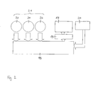
- Figure 1
- shows an apparatus according to the invention,
- Figure 2
- shows a block function diagram of the apparatus shown in
Fig. 1 according to a first embodiment, and - Figure 3
- shows a block function diagram of the apparatus shown in
Fig. 1 according to a second embodiment. - The illustrated embodiments show a tyre changer with a receiving means 10 which is movably in a horizontal direction (as shown with arrow H) and in a vertical direction (as shown with arrow V) and to which a
rim 12 of amotor vehicle wheel 14 can be fixed. Themotor vehicle wheel 14 further comprises atyre 15. The receiving means 10 can have a receiving bar, a wheel plate on which therim 12 is placed, or clamping arms on which therim 12 is supported, or another support arrangement. Therim 12 is non-rotatably connected to the receiving means 10 by fixing means, in particular clamping means. The receiving means 10 is caused to rotate by means of a rotary drive device (not shown) which can be in the form of an electric motor. - The illustrated embodiment also includes at least one fitting or
removal tool 16 which, when themotor vehicle wheel 14 is arranged horizontally, are caused to come into contact with side walls of thetyre 15 from below and from above in the proximity of tyre beads which, when themotor vehicle tyre 15 is in the fitted condition, lie behind two lateral rim beads of therim 12. - The fitting or
removal tools 16 can be operated by anactuator device 17. According to a first embodiment of the invention which is shown inFigure 2 , theactuator device 17 is connected with acomputer 18, thecomputer 18 being send commands to theactuator device 17 to change the position of the fitting orremoval tools 16. The commands are send via an interface (driver circuit) 19 positioned between theactuator device 17 and thecomputer 18. Thecomputer 18 is further connected with asensor device 20 comprising for example sensors, transducers, encoders and/or potentiometers and providing the position of the fitting orremoval tools 16. - At both sides of the rim or of the wheel 14 (that means in the illustrated embodiment at the top side of the
rim 12 or of thewheel 14 and at the underside of therim 12 or of the wheel 14)cameras further camera 26 is disposed on a support movable in a vertical direction and is oriented substantially in a horizontal direction. Thecameras vision system 21 and can be pivotably. - The
cameras cameras wheel 14 is positioned, the fitting orremoval tools 16 operate and an operator acts, images of the rim beads at the radial outer surface of therim 12 and essentially of the rim contour in the region of the rim beads can be produced. Thecameras cameras - The
vision system 21, i.d. thecameras computer 18 to which theactuator device 17 for the fitting orremoval tools 16 and thesensor device 20 are also connected. Thecameras computer 18 which represent created images. - In order to remove a
tyre 15 with the fitting orremoval tools 16, the fitting orremoval tools 16 are guided along the rim contour without contacting the rim contour. For this purpose, thecameras wheel 14 is positioned and the fitting orremoval tools 16 operate, create digital images of the wheel surface and the fitting orremoval tools 16. Corresponding signals were sent to thecomputer 18. As thecameras computer 18 does not detect the coordinates of the photographed elements. But thecomputer 18 detects the relative position of the elements to each other. That means it detects e.g. if the fitting orremoval tools 16 engage the rim contour or are positioned away from the rim contour, but it does not detect how far the fitting or removal tools are positioned away from the rim contour. Thecomputer 18 sends a command to theactuator device 17 to approach the fitting orremoval tools 16 to the rim contour, thesensor device 20 providing the actual position of the fitting orremoval tools 16. Such a command reads e.g. as follows: "Move the fitting or removal tools X cm to the left". Afterwards, thecameras removal tools 16. Corresponding signals were sent to thecomputer 18. Thecomputer 18 correlates the commands sent to theactuator device 17 with the signals (i.e. digital images) received from thecameras computer 18 conducts an image interpretation. Thereby, it compares the initial signals of thecameras cameras removal tools 16, respects the command sent to theactuator device 17 and determines the command which is necessary to approach the fitting orremoval tools 16 to the rim contour. The method is repeated as long as the fitting orremoval tools 16 lies in the desired position relative to the rim contour. Thecameras removal tools 16 can be approached to the rim contour. - Furthermore, with the
cameras computer 18. After correlation of several signals, a dangerous situation for the operator can be detected and the method can be stopped. The method and apparatus according to the invention can be used to avoid collisions between the fitting or removal tools and the wheel, rim and/or tyre, between various tools (i.e. fitting or removal tool and hold-down device). Further, the method and apparatus according to the invention allows stopping the method in case of potential damage for the wheel, the tyre and/or the operator. - The first embodiment of the invention showing in
Figure 2 differs from the second embodiment in that there are provided two computers, namely afirst computer 28 and asecond computer 30. The first and thesecond computer first computer 28 is also connected with thecameras cameras first computer 28 and afterwards to thesecond computer 30. Theactuator device 17 and thesensor device 20 are connected with thesecond computer 30. The other components of the apparatus according to the second embodiment and the method correspond to the first embodiment to which it is referred herewith.
Claims (12)
- Method for mounting a tyre on a rim to form a motor vehicle wheel and for demounting a tyre from a rim with at least one fitting or removal tool, wherein images of the wheel (14) or the rim (12) are created by a vision system (21) and corresponding signals are sent to a computer (18; 28), wherein commands to move the at least one fitting or removal tool (16) are sent to the at least one fitting or removal tool (16) by the computer (18; 30), wherein the signals of the vision system (21) and the commands sent to the at least one fitting or removal tool (16) are correlated to define the position of the at least one fitting or removal tool relative to the rim contour and wherein the movement of the at least one fitting or removal tool (16) is guided in dependence on the performed correlation without contacting the rim surface.
- Method according to claim 1,
wherein signals of the vision system (21) are sent to the computer (18) and commands to the at least one fitting or removal tool (16) are sent from the computer (18). - Method according to claim 1,
wherein signals of the vision system (21) are sent to a second computer (28), the second computer (28) is connected with a computer (30), commands to the at least one fitting or removal tool (16) are sent from the computer (30). - Method according to one of the preceding claims,
wherein a plurality of images are created during the mounting or demounting operation by the vision system (21). - Apparatus for mounting a tyre on a rim to form a motor vehicle wheel and for demounting a tyre from a rim, comprising
at least one fitting or removal tool (16) for mounting and demounting the tyre (15),
a computer (18; 30) being able to send commands for the movement of the at least one fitting or removal tool (16),
a vision system (21) for creating images of the wheel (14) or the rim (12), wherein the vision system (21) is connected with the computer (18; 28), signals corresponding to the created images being sent to the computer (18; 30),
wherein the computer (18; 30) correlates the signals of the vision system (21) and the commands sent to the at least one fitting or removal tool (16) to define the position of the at least one fitting or removal tool (16) relative to the rim contour and to guide the at least one fitting or removal tool (16) in dependence on the performed correlation without contacting the rim surface. - Apparatus according to claim 5,
wherein vision system (21) creates two-dimensional images. - Apparatus according to claim 5 or claim 6,
wherein the vision system (21) comprises at least one camera (22, 24, 26) for creating images. - Apparatus according to one of the claims 5 to 7,
wherein the vision system (21) is uncalibrated - Apparatus according to one of the claims 5 to 8,
wherein an actuator device (17) is provided operating the at least one fitting or removal tool (16). - Apparatus according to one of the claims 5 to 9,
wherein a sensor device (20) is connected with the computer (18; 30) providing the position of the at least one fitting or removal tool (16). - Apparatus according to one of the claims 5 to 10,
wherein the vision system (21) is connected with the computer (18) and the computer (18) is connected with the at least one fitting or removal tool (16). - Apparatus according to one of the claims 5 to 10,
wherein a second computer (28) is provided, the second computer (28) is connected with the vision system (21) and with the computer (30), commands to the at least one fitting or removal tool (16) are sent from the computer (30).
Priority Applications (6)
| Application Number | Priority Date | Filing Date | Title |
|---|---|---|---|
| AT10000545T ATE551212T1 (en) | 2010-01-20 | 2010-01-20 | METHOD FOR ATTACHING A TIRE TO A RIM TO OBTAIN A VEHICLE WHEEL AND METHOD FOR REMOVALING A TIRE FROM A RIM AND DEVICE THEREOF |
| ES10000545T ES2383734T3 (en) | 2010-01-20 | 2010-01-20 | Procedure and apparatus for mounting a tire on a tire to form a motor vehicle wheel and for disassembling a tire from a tire |
| EP10000545A EP2347919B1 (en) | 2010-01-20 | 2010-01-20 | Method for mounting a tyre on a rim to form a motor vehicle wheel and for demounting a tyre from a rim and apparatus therefore |
| CN201010556491.XA CN102126405B (en) | 2010-01-20 | 2010-11-18 | For method and apparatus tire is installed on wheel rim and pull down from wheel rim |
| US12/959,087 US8342222B2 (en) | 2010-01-20 | 2010-12-02 | Method for mounting a tyre on a rim to form a motor vehicle wheel and for demounting a tyre from a rim and apparatus therefore |
| HK11112425.7A HK1158145B (en) | 2011-11-17 | Method for mounting a tyre on a rim to form a motor vehicle wheel and for demounting a tyre from a rim and apparatus therefore |
Applications Claiming Priority (1)
| Application Number | Priority Date | Filing Date | Title |
|---|---|---|---|
| EP10000545A EP2347919B1 (en) | 2010-01-20 | 2010-01-20 | Method for mounting a tyre on a rim to form a motor vehicle wheel and for demounting a tyre from a rim and apparatus therefore |
Publications (2)
| Publication Number | Publication Date |
|---|---|
| EP2347919A1 true EP2347919A1 (en) | 2011-07-27 |
| EP2347919B1 EP2347919B1 (en) | 2012-03-28 |
Family
ID=42236273
Family Applications (1)
| Application Number | Title | Priority Date | Filing Date |
|---|---|---|---|
| EP10000545A Active EP2347919B1 (en) | 2010-01-20 | 2010-01-20 | Method for mounting a tyre on a rim to form a motor vehicle wheel and for demounting a tyre from a rim and apparatus therefore |
Country Status (5)
| Country | Link |
|---|---|
| US (1) | US8342222B2 (en) |
| EP (1) | EP2347919B1 (en) |
| CN (1) | CN102126405B (en) |
| AT (1) | ATE551212T1 (en) |
| ES (1) | ES2383734T3 (en) |
Cited By (3)
| Publication number | Priority date | Publication date | Assignee | Title |
|---|---|---|---|---|
| EP3269569A1 (en) | 2016-07-13 | 2018-01-17 | Snap-on Equipment S.r.l. | Method and apparatus for uniquely identifying tyres for wheels of vehicles as part of vehicle wheel maintenance processes |
| EP2949486B1 (en) | 2014-05-30 | 2019-01-09 | Snap-on Equipment Srl a unico socio | Method for mounting and demounting a tyre to and from a wheel rim |
| IT202100018722A1 (en) | 2021-07-16 | 2023-01-16 | Snap On Equip Srl Unico Socio | Tire changer |
Families Citing this family (12)
| Publication number | Priority date | Publication date | Assignee | Title |
|---|---|---|---|---|
| US8284390B1 (en) | 2003-02-20 | 2012-10-09 | Hunter Engineering Company | Vehicle tire changing system with tool positioning sensor |
| US8783326B1 (en) * | 2009-09-09 | 2014-07-22 | Hunter Engineering Company | Tire changing machine with automated tire bead pressing devices, controls and methods |
| EP2634016B1 (en) * | 2010-02-17 | 2017-12-20 | Snap-on Equipment Srl a unico socio | Tyre changer and a method of measuring force variations acting between a peripheral surface of a wheel/tyre assembly and a roller |
| ITMO20120191A1 (en) * | 2012-07-31 | 2014-02-01 | Sicam Srl | TIRE CHANGER MACHINE FOR THE ASSEMBLY AND DISASSEMBLY OF VEHICLE WHEELS |
| CN105598974B (en) * | 2016-02-25 | 2017-11-17 | 深圳市华成工业控制有限公司 | Robot movement method and its system |
| CN106183665B (en) * | 2016-08-26 | 2019-04-02 | 营口辽南德威机械设备有限公司 | A kind of tire changer |
| IT201700065506A1 (en) * | 2017-06-13 | 2018-12-13 | Snap On Equipment S R L A Unico Socio | METHOD AND PROCESS PERFORMED TO ASSEMBLE OR DISASSEMBLE TIRES ON RIMS |
| IT201700086220A1 (en) * | 2017-07-27 | 2019-01-27 | Butler Eng And Marketing S P A | MACHINE AND METHOD OF TREATMENT OF A WHEELED WHEEL |
| CN114919331B (en) * | 2022-06-28 | 2023-10-03 | 富士达电动车(江苏)有限公司 | An automatic wheel rim wire locking and positioning machine for electric vehicles |
| CN115648231B (en) * | 2022-12-29 | 2023-03-21 | 无锡黎曼机器人科技有限公司 | Size and position recognition and grabbing control method and control system for tire blank |
| US20250315977A1 (en) | 2024-04-08 | 2025-10-09 | Snap-On Equipment Srl A Unico Socio | Application of ai-based image processing in vehicle wheel servicing |
| USD1110380S1 (en) | 2025-01-14 | 2026-01-27 | Haiyu Zhang | Tire changer |
Citations (5)
| Publication number | Priority date | Publication date | Assignee | Title |
|---|---|---|---|---|
| US3877505A (en) | 1973-01-30 | 1975-04-15 | David W Besuden | Upper bead breaker mechanism |
| US20040165180A1 (en) * | 2003-02-20 | 2004-08-26 | David Voeller | Method and apparatus for vehicle service system with imaging components |
| EP1927484A1 (en) | 2006-11-28 | 2008-06-04 | G.S. S.r.L. | Method of and apparatus for determining geometrical dimensions of a wheel rim, in particular when fitting and/or removing a motor vehicle tyre |
| EP1995083A1 (en) | 2007-05-23 | 2008-11-26 | Snap-on Equipment Srl a unico socio. | Method of and apparatus for determining geometrical dimension of a vehicle wheel comprising optical sensors |
| EP2110270A1 (en) * | 2008-04-17 | 2009-10-21 | Snap-on Equipment Srl a unico socio. | Method of and apparatus for fitting or removing a motor vehicle tyre |
Family Cites Families (5)
| Publication number | Priority date | Publication date | Assignee | Title |
|---|---|---|---|---|
| JPH04341835A (en) * | 1991-05-17 | 1992-11-27 | Bridgestone Corp | Skiving apparatus for reclaimed tire |
| IT1319468B1 (en) * | 2000-05-22 | 2003-10-10 | Corghi Spa | AUTOMATIC Bead breaker device for tire changers, tire changers so equipped |
| ITVR20030062A1 (en) * | 2003-05-19 | 2004-11-20 | Butler Eng & Marketing | MAINTENANCE EQUIPMENT OF A WHEELED WHEEL |
| US7199873B2 (en) * | 2004-01-27 | 2007-04-03 | Snap-On Equipment Srl A Unico Socio | Method and apparatus for balancing a motor vehicle wheel |
| IT1391808B1 (en) * | 2008-10-31 | 2012-01-27 | Sicam Srl | MALE DISPENSER FOR THE ASSEMBLY AND DISASSEMBLY OF VEHICLE WHEELS |
-
2010
- 2010-01-20 AT AT10000545T patent/ATE551212T1/en active
- 2010-01-20 EP EP10000545A patent/EP2347919B1/en active Active
- 2010-01-20 ES ES10000545T patent/ES2383734T3/en active Active
- 2010-11-18 CN CN201010556491.XA patent/CN102126405B/en active Active
- 2010-12-02 US US12/959,087 patent/US8342222B2/en active Active
Patent Citations (5)
| Publication number | Priority date | Publication date | Assignee | Title |
|---|---|---|---|---|
| US3877505A (en) | 1973-01-30 | 1975-04-15 | David W Besuden | Upper bead breaker mechanism |
| US20040165180A1 (en) * | 2003-02-20 | 2004-08-26 | David Voeller | Method and apparatus for vehicle service system with imaging components |
| EP1927484A1 (en) | 2006-11-28 | 2008-06-04 | G.S. S.r.L. | Method of and apparatus for determining geometrical dimensions of a wheel rim, in particular when fitting and/or removing a motor vehicle tyre |
| EP1995083A1 (en) | 2007-05-23 | 2008-11-26 | Snap-on Equipment Srl a unico socio. | Method of and apparatus for determining geometrical dimension of a vehicle wheel comprising optical sensors |
| EP2110270A1 (en) * | 2008-04-17 | 2009-10-21 | Snap-on Equipment Srl a unico socio. | Method of and apparatus for fitting or removing a motor vehicle tyre |
Cited By (7)
| Publication number | Priority date | Publication date | Assignee | Title |
|---|---|---|---|---|
| EP2949486B1 (en) | 2014-05-30 | 2019-01-09 | Snap-on Equipment Srl a unico socio | Method for mounting and demounting a tyre to and from a wheel rim |
| US11214103B2 (en) | 2014-05-30 | 2022-01-04 | Snap-On Equipment Srl A Unico Socio | Method for mounting and demounting a tyre to and from a wheel rim |
| EP2949486B2 (en) † | 2014-05-30 | 2022-04-13 | Snap-on Equipment Srl a unico socio | Method for mounting and demounting a tyre to and from a wheel rim |
| EP3269569A1 (en) | 2016-07-13 | 2018-01-17 | Snap-on Equipment S.r.l. | Method and apparatus for uniquely identifying tyres for wheels of vehicles as part of vehicle wheel maintenance processes |
| US10654323B2 (en) | 2016-07-13 | 2020-05-19 | Snap-On Equipment S.R.L. | Method and apparatus for uniquely identifying tyres for wheels of vehicles as part of vehicle wheel maintenance processes |
| IT202100018722A1 (en) | 2021-07-16 | 2023-01-16 | Snap On Equip Srl Unico Socio | Tire changer |
| EP4119366A1 (en) | 2021-07-16 | 2023-01-18 | Snap-on Equipment Srl a unico socio | Tire changer |
Also Published As
| Publication number | Publication date |
|---|---|
| ES2383734T3 (en) | 2012-06-25 |
| US8342222B2 (en) | 2013-01-01 |
| US20110174446A1 (en) | 2011-07-21 |
| ATE551212T1 (en) | 2012-04-15 |
| HK1158145A1 (en) | 2012-07-13 |
| CN102126405B (en) | 2016-01-20 |
| CN102126405A (en) | 2011-07-20 |
| EP2347919B1 (en) | 2012-03-28 |
Similar Documents
| Publication | Publication Date | Title |
|---|---|---|
| EP2347919B1 (en) | Method for mounting a tyre on a rim to form a motor vehicle wheel and for demounting a tyre from a rim and apparatus therefore | |
| US7768632B2 (en) | Method of and apparatus for determining geometrical dimensions of a vehicle wheel | |
| US7715024B2 (en) | Method of and apparatus for determining geometrical dimensions of a wheel rim, in particular when fitting and/or removing a motor vehicle tyre | |
| EP2716590B1 (en) | Apparatus for guiding a vehicle onto a service lift | |
| US8342223B2 (en) | Method of and apparatus for fitting or removing a motor vehicle tyre | |
| US7738120B2 (en) | Method and apparatus for determining geometrical dimensions of a vehicle wheel | |
| CN109477313B (en) | System and method for measuring a track | |
| EP2353890A1 (en) | Apparatus and method of determing geometrical dimensions of a tyre with optical sensors | |
| AU2018201797A1 (en) | Vehicle alignment systems for loading docks | |
| WO2016181733A1 (en) | Forklift | |
| JP2015032182A (en) | Autonomous mobile device and control method of the same | |
| US10451400B2 (en) | Machine and method for monitoring a coordinate measuring device | |
| JP5537027B2 (en) | Imaging and safety systems and methods for industrial machines | |
| HK1158145B (en) | Method for mounting a tyre on a rim to form a motor vehicle wheel and for demounting a tyre from a rim and apparatus therefore | |
| JP6174274B2 (en) | Crane system and processing method | |
| JP2010122045A (en) | Pcs sensor radio wave axis adjustment apparatus and its method | |
| JP2023080414A (en) | Vehicle sensor mounting structure | |
| WO2021235039A1 (en) | Mobile robot | |
| HK1158147A (en) | Apparatus and method of determing geometrical dimensions of a tyre with optical sensors |
Legal Events
| Date | Code | Title | Description |
|---|---|---|---|
| PUAI | Public reference made under article 153(3) epc to a published international application that has entered the european phase |
Free format text: ORIGINAL CODE: 0009012 |
|
| 17P | Request for examination filed |
Effective date: 20100920 |
|
| AK | Designated contracting states |
Kind code of ref document: A1 Designated state(s): AT BE BG CH CY CZ DE DK EE ES FI FR GB GR HR HU IE IS IT LI LT LU LV MC MK MT NL NO PL PT RO SE SI SK SM TR |
|
| AX | Request for extension of the european patent |
Extension state: AL BA RS |
|
| GRAP | Despatch of communication of intention to grant a patent |
Free format text: ORIGINAL CODE: EPIDOSNIGR1 |
|
| RIC1 | Information provided on ipc code assigned before grant |
Ipc: B25J 9/16 20060101ALI20110907BHEP Ipc: B60C 25/138 20060101AFI20110907BHEP |
|
| GRAS | Grant fee paid |
Free format text: ORIGINAL CODE: EPIDOSNIGR3 |
|
| GRAA | (expected) grant |
Free format text: ORIGINAL CODE: 0009210 |
|
| AK | Designated contracting states |
Kind code of ref document: B1 Designated state(s): AT BE BG CH CY CZ DE DK EE ES FI FR GB GR HR HU IE IS IT LI LT LU LV MC MK MT NL NO PL PT RO SE SI SK SM TR |
|
| REG | Reference to a national code |
Ref country code: GB Ref legal event code: FG4D |
|
| REG | Reference to a national code |
Ref country code: CH Ref legal event code: EP |
|
| REG | Reference to a national code |
Ref country code: AT Ref legal event code: REF Ref document number: 551212 Country of ref document: AT Kind code of ref document: T Effective date: 20120415 |
|
| REG | Reference to a national code |
Ref country code: IE Ref legal event code: FG4D |
|
| REG | Reference to a national code |
Ref country code: DE Ref legal event code: R096 Ref document number: 602010001156 Country of ref document: DE Effective date: 20120524 |
|
| REG | Reference to a national code |
Ref country code: ES Ref legal event code: FG2A Ref document number: 2383734 Country of ref document: ES Kind code of ref document: T3 Effective date: 20120625 |
|
| REG | Reference to a national code |
Ref country code: HK Ref legal event code: DE Ref document number: 1158145 Country of ref document: HK |
|
| REG | Reference to a national code |
Ref country code: NL Ref legal event code: VDEP Effective date: 20120328 |
|
| PG25 | Lapsed in a contracting state [announced via postgrant information from national office to epo] |
Ref country code: LT Free format text: LAPSE BECAUSE OF FAILURE TO SUBMIT A TRANSLATION OF THE DESCRIPTION OR TO PAY THE FEE WITHIN THE PRESCRIBED TIME-LIMIT Effective date: 20120328 Ref country code: HR Free format text: LAPSE BECAUSE OF FAILURE TO SUBMIT A TRANSLATION OF THE DESCRIPTION OR TO PAY THE FEE WITHIN THE PRESCRIBED TIME-LIMIT Effective date: 20120328 Ref country code: NO Free format text: LAPSE BECAUSE OF FAILURE TO SUBMIT A TRANSLATION OF THE DESCRIPTION OR TO PAY THE FEE WITHIN THE PRESCRIBED TIME-LIMIT Effective date: 20120628 |
|
| LTIE | Lt: invalidation of european patent or patent extension |
Effective date: 20120328 |
|
| PG25 | Lapsed in a contracting state [announced via postgrant information from national office to epo] |
Ref country code: GR Free format text: LAPSE BECAUSE OF FAILURE TO SUBMIT A TRANSLATION OF THE DESCRIPTION OR TO PAY THE FEE WITHIN THE PRESCRIBED TIME-LIMIT Effective date: 20120629 Ref country code: FI Free format text: LAPSE BECAUSE OF FAILURE TO SUBMIT A TRANSLATION OF THE DESCRIPTION OR TO PAY THE FEE WITHIN THE PRESCRIBED TIME-LIMIT Effective date: 20120328 Ref country code: LV Free format text: LAPSE BECAUSE OF FAILURE TO SUBMIT A TRANSLATION OF THE DESCRIPTION OR TO PAY THE FEE WITHIN THE PRESCRIBED TIME-LIMIT Effective date: 20120328 |
|
| REG | Reference to a national code |
Ref country code: AT Ref legal event code: MK05 Ref document number: 551212 Country of ref document: AT Kind code of ref document: T Effective date: 20120328 |
|
| PG25 | Lapsed in a contracting state [announced via postgrant information from national office to epo] |
Ref country code: CY Free format text: LAPSE BECAUSE OF FAILURE TO SUBMIT A TRANSLATION OF THE DESCRIPTION OR TO PAY THE FEE WITHIN THE PRESCRIBED TIME-LIMIT Effective date: 20120328 |
|
| PG25 | Lapsed in a contracting state [announced via postgrant information from national office to epo] |
Ref country code: SI Free format text: LAPSE BECAUSE OF FAILURE TO SUBMIT A TRANSLATION OF THE DESCRIPTION OR TO PAY THE FEE WITHIN THE PRESCRIBED TIME-LIMIT Effective date: 20120328 Ref country code: RO Free format text: LAPSE BECAUSE OF FAILURE TO SUBMIT A TRANSLATION OF THE DESCRIPTION OR TO PAY THE FEE WITHIN THE PRESCRIBED TIME-LIMIT Effective date: 20120328 Ref country code: IS Free format text: LAPSE BECAUSE OF FAILURE TO SUBMIT A TRANSLATION OF THE DESCRIPTION OR TO PAY THE FEE WITHIN THE PRESCRIBED TIME-LIMIT Effective date: 20120728 Ref country code: PL Free format text: LAPSE BECAUSE OF FAILURE TO SUBMIT A TRANSLATION OF THE DESCRIPTION OR TO PAY THE FEE WITHIN THE PRESCRIBED TIME-LIMIT Effective date: 20120328 Ref country code: CZ Free format text: LAPSE BECAUSE OF FAILURE TO SUBMIT A TRANSLATION OF THE DESCRIPTION OR TO PAY THE FEE WITHIN THE PRESCRIBED TIME-LIMIT Effective date: 20120328 Ref country code: SE Free format text: LAPSE BECAUSE OF FAILURE TO SUBMIT A TRANSLATION OF THE DESCRIPTION OR TO PAY THE FEE WITHIN THE PRESCRIBED TIME-LIMIT Effective date: 20120328 Ref country code: EE Free format text: LAPSE BECAUSE OF FAILURE TO SUBMIT A TRANSLATION OF THE DESCRIPTION OR TO PAY THE FEE WITHIN THE PRESCRIBED TIME-LIMIT Effective date: 20120328 Ref country code: BE Free format text: LAPSE BECAUSE OF FAILURE TO SUBMIT A TRANSLATION OF THE DESCRIPTION OR TO PAY THE FEE WITHIN THE PRESCRIBED TIME-LIMIT Effective date: 20120328 |
|
| REG | Reference to a national code |
Ref country code: HK Ref legal event code: GR Ref document number: 1158145 Country of ref document: HK |
|
| PG25 | Lapsed in a contracting state [announced via postgrant information from national office to epo] |
Ref country code: SK Free format text: LAPSE BECAUSE OF FAILURE TO SUBMIT A TRANSLATION OF THE DESCRIPTION OR TO PAY THE FEE WITHIN THE PRESCRIBED TIME-LIMIT Effective date: 20120328 Ref country code: PT Free format text: LAPSE BECAUSE OF FAILURE TO SUBMIT A TRANSLATION OF THE DESCRIPTION OR TO PAY THE FEE WITHIN THE PRESCRIBED TIME-LIMIT Effective date: 20120730 |
|
| PG25 | Lapsed in a contracting state [announced via postgrant information from national office to epo] |
Ref country code: AT Free format text: LAPSE BECAUSE OF FAILURE TO SUBMIT A TRANSLATION OF THE DESCRIPTION OR TO PAY THE FEE WITHIN THE PRESCRIBED TIME-LIMIT Effective date: 20120328 Ref country code: NL Free format text: LAPSE BECAUSE OF FAILURE TO SUBMIT A TRANSLATION OF THE DESCRIPTION OR TO PAY THE FEE WITHIN THE PRESCRIBED TIME-LIMIT Effective date: 20120328 Ref country code: DK Free format text: LAPSE BECAUSE OF FAILURE TO SUBMIT A TRANSLATION OF THE DESCRIPTION OR TO PAY THE FEE WITHIN THE PRESCRIBED TIME-LIMIT Effective date: 20120328 |
|
| PLBE | No opposition filed within time limit |
Free format text: ORIGINAL CODE: 0009261 |
|
| STAA | Information on the status of an ep patent application or granted ep patent |
Free format text: STATUS: NO OPPOSITION FILED WITHIN TIME LIMIT |
|
| 26N | No opposition filed |
Effective date: 20130103 |
|
| REG | Reference to a national code |
Ref country code: DE Ref legal event code: R097 Ref document number: 602010001156 Country of ref document: DE Effective date: 20130103 |
|
| PG25 | Lapsed in a contracting state [announced via postgrant information from national office to epo] |
Ref country code: BG Free format text: LAPSE BECAUSE OF FAILURE TO SUBMIT A TRANSLATION OF THE DESCRIPTION OR TO PAY THE FEE WITHIN THE PRESCRIBED TIME-LIMIT Effective date: 20120628 |
|
| PG25 | Lapsed in a contracting state [announced via postgrant information from national office to epo] |
Ref country code: MC Free format text: LAPSE BECAUSE OF NON-PAYMENT OF DUE FEES Effective date: 20130131 |
|
| REG | Reference to a national code |
Ref country code: IE Ref legal event code: MM4A |
|
| PG25 | Lapsed in a contracting state [announced via postgrant information from national office to epo] |
Ref country code: IE Free format text: LAPSE BECAUSE OF NON-PAYMENT OF DUE FEES Effective date: 20130120 |
|
| PGFP | Annual fee paid to national office [announced via postgrant information from national office to epo] |
Ref country code: ES Payment date: 20140122 Year of fee payment: 5 Ref country code: FR Payment date: 20140124 Year of fee payment: 5 |
|
| PG25 | Lapsed in a contracting state [announced via postgrant information from national office to epo] |
Ref country code: MT Free format text: LAPSE BECAUSE OF FAILURE TO SUBMIT A TRANSLATION OF THE DESCRIPTION OR TO PAY THE FEE WITHIN THE PRESCRIBED TIME-LIMIT Effective date: 20120328 |
|
| PGFP | Annual fee paid to national office [announced via postgrant information from national office to epo] |
Ref country code: GB Payment date: 20140123 Year of fee payment: 5 |
|
| REG | Reference to a national code |
Ref country code: CH Ref legal event code: PL |
|
| PG25 | Lapsed in a contracting state [announced via postgrant information from national office to epo] |
Ref country code: LI Free format text: LAPSE BECAUSE OF NON-PAYMENT OF DUE FEES Effective date: 20140131 Ref country code: CH Free format text: LAPSE BECAUSE OF NON-PAYMENT OF DUE FEES Effective date: 20140131 |
|
| PG25 | Lapsed in a contracting state [announced via postgrant information from national office to epo] |
Ref country code: SM Free format text: LAPSE BECAUSE OF FAILURE TO SUBMIT A TRANSLATION OF THE DESCRIPTION OR TO PAY THE FEE WITHIN THE PRESCRIBED TIME-LIMIT Effective date: 20120328 |
|
| PG25 | Lapsed in a contracting state [announced via postgrant information from national office to epo] |
Ref country code: TR Free format text: LAPSE BECAUSE OF FAILURE TO SUBMIT A TRANSLATION OF THE DESCRIPTION OR TO PAY THE FEE WITHIN THE PRESCRIBED TIME-LIMIT Effective date: 20120328 |
|
| PG25 | Lapsed in a contracting state [announced via postgrant information from national office to epo] |
Ref country code: MK Free format text: LAPSE BECAUSE OF FAILURE TO SUBMIT A TRANSLATION OF THE DESCRIPTION OR TO PAY THE FEE WITHIN THE PRESCRIBED TIME-LIMIT Effective date: 20120328 Ref country code: LU Free format text: LAPSE BECAUSE OF NON-PAYMENT OF DUE FEES Effective date: 20130120 Ref country code: HU Free format text: LAPSE BECAUSE OF FAILURE TO SUBMIT A TRANSLATION OF THE DESCRIPTION OR TO PAY THE FEE WITHIN THE PRESCRIBED TIME-LIMIT; INVALID AB INITIO Effective date: 20100120 |
|
| GBPC | Gb: european patent ceased through non-payment of renewal fee |
Effective date: 20150120 |
|
| PG25 | Lapsed in a contracting state [announced via postgrant information from national office to epo] |
Ref country code: GB Free format text: LAPSE BECAUSE OF NON-PAYMENT OF DUE FEES Effective date: 20150120 |
|
| REG | Reference to a national code |
Ref country code: FR Ref legal event code: ST Effective date: 20150930 |
|
| PG25 | Lapsed in a contracting state [announced via postgrant information from national office to epo] |
Ref country code: FR Free format text: LAPSE BECAUSE OF NON-PAYMENT OF DUE FEES Effective date: 20150202 |
|
| REG | Reference to a national code |
Ref country code: ES Ref legal event code: FD2A Effective date: 20160226 |
|
| PG25 | Lapsed in a contracting state [announced via postgrant information from national office to epo] |
Ref country code: ES Free format text: LAPSE BECAUSE OF NON-PAYMENT OF DUE FEES Effective date: 20150121 |
|
| P01 | Opt-out of the competence of the unified patent court (upc) registered |
Effective date: 20230517 |
|
| PGFP | Annual fee paid to national office [announced via postgrant information from national office to epo] |
Ref country code: DE Payment date: 20260128 Year of fee payment: 17 |
|
| PGFP | Annual fee paid to national office [announced via postgrant information from national office to epo] |
Ref country code: IT Payment date: 20260121 Year of fee payment: 17 |