EP3269527A1 - Method and system for producing three-dimensional build objects - Google Patents
Method and system for producing three-dimensional build objects Download PDFInfo
- Publication number
- EP3269527A1 EP3269527A1 EP17177869.9A EP17177869A EP3269527A1 EP 3269527 A1 EP3269527 A1 EP 3269527A1 EP 17177869 A EP17177869 A EP 17177869A EP 3269527 A1 EP3269527 A1 EP 3269527A1
- Authority
- EP
- European Patent Office
- Prior art keywords
- extruder
- actuator
- build
- ribbon
- build material
- Prior art date
- Legal status (The legal status is an assumption and is not a legal conclusion. Google has not performed a legal analysis and makes no representation as to the accuracy of the status listed.)
- Granted
Links
Images




Classifications
-
- B—PERFORMING OPERATIONS; TRANSPORTING
- B29—WORKING OF PLASTICS; WORKING OF SUBSTANCES IN A PLASTIC STATE IN GENERAL
- B29C—SHAPING OR JOINING OF PLASTICS; SHAPING OF MATERIAL IN A PLASTIC STATE, NOT OTHERWISE PROVIDED FOR; AFTER-TREATMENT OF THE SHAPED PRODUCTS, e.g. REPAIRING
- B29C48/00—Extrusion moulding, i.e. expressing the moulding material through a die or nozzle which imparts the desired form; Apparatus therefor
- B29C48/03—Extrusion moulding, i.e. expressing the moulding material through a die or nozzle which imparts the desired form; Apparatus therefor characterised by the shape of the extruded material at extrusion
- B29C48/07—Flat, e.g. panels
-
- B—PERFORMING OPERATIONS; TRANSPORTING
- B29—WORKING OF PLASTICS; WORKING OF SUBSTANCES IN A PLASTIC STATE IN GENERAL
- B29C—SHAPING OR JOINING OF PLASTICS; SHAPING OF MATERIAL IN A PLASTIC STATE, NOT OTHERWISE PROVIDED FOR; AFTER-TREATMENT OF THE SHAPED PRODUCTS, e.g. REPAIRING
- B29C48/00—Extrusion moulding, i.e. expressing the moulding material through a die or nozzle which imparts the desired form; Apparatus therefor
- B29C48/02—Small extruding apparatus, e.g. handheld, toy or laboratory extruders
-
- B—PERFORMING OPERATIONS; TRANSPORTING
- B29—WORKING OF PLASTICS; WORKING OF SUBSTANCES IN A PLASTIC STATE IN GENERAL
- B29C—SHAPING OR JOINING OF PLASTICS; SHAPING OF MATERIAL IN A PLASTIC STATE, NOT OTHERWISE PROVIDED FOR; AFTER-TREATMENT OF THE SHAPED PRODUCTS, e.g. REPAIRING
- B29C64/00—Additive manufacturing, i.e. manufacturing of three-dimensional [3D] objects by additive deposition, additive agglomeration or additive layering, e.g. by 3D printing, stereolithography or selective laser sintering
- B29C64/10—Processes of additive manufacturing
- B29C64/106—Processes of additive manufacturing using only liquids or viscous materials, e.g. depositing a continuous bead of viscous material
-
- B—PERFORMING OPERATIONS; TRANSPORTING
- B29—WORKING OF PLASTICS; WORKING OF SUBSTANCES IN A PLASTIC STATE IN GENERAL
- B29C—SHAPING OR JOINING OF PLASTICS; SHAPING OF MATERIAL IN A PLASTIC STATE, NOT OTHERWISE PROVIDED FOR; AFTER-TREATMENT OF THE SHAPED PRODUCTS, e.g. REPAIRING
- B29C64/00—Additive manufacturing, i.e. manufacturing of three-dimensional [3D] objects by additive deposition, additive agglomeration or additive layering, e.g. by 3D printing, stereolithography or selective laser sintering
- B29C64/10—Processes of additive manufacturing
- B29C64/106—Processes of additive manufacturing using only liquids or viscous materials, e.g. depositing a continuous bead of viscous material
- B29C64/118—Processes of additive manufacturing using only liquids or viscous materials, e.g. depositing a continuous bead of viscous material using filamentary material being melted, e.g. fused deposition modelling [FDM]
-
- B—PERFORMING OPERATIONS; TRANSPORTING
- B29—WORKING OF PLASTICS; WORKING OF SUBSTANCES IN A PLASTIC STATE IN GENERAL
- B29C—SHAPING OR JOINING OF PLASTICS; SHAPING OF MATERIAL IN A PLASTIC STATE, NOT OTHERWISE PROVIDED FOR; AFTER-TREATMENT OF THE SHAPED PRODUCTS, e.g. REPAIRING
- B29C64/00—Additive manufacturing, i.e. manufacturing of three-dimensional [3D] objects by additive deposition, additive agglomeration or additive layering, e.g. by 3D printing, stereolithography or selective laser sintering
- B29C64/20—Apparatus for additive manufacturing; Details thereof or accessories therefor
- B29C64/205—Means for applying layers
- B29C64/209—Heads; Nozzles
-
- B—PERFORMING OPERATIONS; TRANSPORTING
- B29—WORKING OF PLASTICS; WORKING OF SUBSTANCES IN A PLASTIC STATE IN GENERAL
- B29C—SHAPING OR JOINING OF PLASTICS; SHAPING OF MATERIAL IN A PLASTIC STATE, NOT OTHERWISE PROVIDED FOR; AFTER-TREATMENT OF THE SHAPED PRODUCTS, e.g. REPAIRING
- B29C64/00—Additive manufacturing, i.e. manufacturing of three-dimensional [3D] objects by additive deposition, additive agglomeration or additive layering, e.g. by 3D printing, stereolithography or selective laser sintering
- B29C64/20—Apparatus for additive manufacturing; Details thereof or accessories therefor
- B29C64/227—Driving means
- B29C64/236—Driving means for motion in a direction within the plane of a layer
-
- B—PERFORMING OPERATIONS; TRANSPORTING
- B29—WORKING OF PLASTICS; WORKING OF SUBSTANCES IN A PLASTIC STATE IN GENERAL
- B29C—SHAPING OR JOINING OF PLASTICS; SHAPING OF MATERIAL IN A PLASTIC STATE, NOT OTHERWISE PROVIDED FOR; AFTER-TREATMENT OF THE SHAPED PRODUCTS, e.g. REPAIRING
- B29C64/00—Additive manufacturing, i.e. manufacturing of three-dimensional [3D] objects by additive deposition, additive agglomeration or additive layering, e.g. by 3D printing, stereolithography or selective laser sintering
- B29C64/30—Auxiliary operations or equipment
- B29C64/386—Data acquisition or data processing for additive manufacturing
-
- B—PERFORMING OPERATIONS; TRANSPORTING
- B29—WORKING OF PLASTICS; WORKING OF SUBSTANCES IN A PLASTIC STATE IN GENERAL
- B29C—SHAPING OR JOINING OF PLASTICS; SHAPING OF MATERIAL IN A PLASTIC STATE, NOT OTHERWISE PROVIDED FOR; AFTER-TREATMENT OF THE SHAPED PRODUCTS, e.g. REPAIRING
- B29C64/00—Additive manufacturing, i.e. manufacturing of three-dimensional [3D] objects by additive deposition, additive agglomeration or additive layering, e.g. by 3D printing, stereolithography or selective laser sintering
- B29C64/30—Auxiliary operations or equipment
- B29C64/386—Data acquisition or data processing for additive manufacturing
- B29C64/393—Data acquisition or data processing for additive manufacturing for controlling or regulating additive manufacturing processes
-
- B—PERFORMING OPERATIONS; TRANSPORTING
- B33—ADDITIVE MANUFACTURING TECHNOLOGY
- B33Y—ADDITIVE MANUFACTURING, i.e. MANUFACTURING OF THREE-DIMENSIONAL [3D] OBJECTS BY ADDITIVE DEPOSITION, ADDITIVE AGGLOMERATION OR ADDITIVE LAYERING, e.g. BY 3D PRINTING, STEREOLITHOGRAPHY OR SELECTIVE LASER SINTERING
- B33Y10/00—Processes of additive manufacturing
-
- B—PERFORMING OPERATIONS; TRANSPORTING
- B33—ADDITIVE MANUFACTURING TECHNOLOGY
- B33Y—ADDITIVE MANUFACTURING, i.e. MANUFACTURING OF THREE-DIMENSIONAL [3D] OBJECTS BY ADDITIVE DEPOSITION, ADDITIVE AGGLOMERATION OR ADDITIVE LAYERING, e.g. BY 3D PRINTING, STEREOLITHOGRAPHY OR SELECTIVE LASER SINTERING
- B33Y30/00—Apparatus for additive manufacturing; Details thereof or accessories therefor
-
- B—PERFORMING OPERATIONS; TRANSPORTING
- B33—ADDITIVE MANUFACTURING TECHNOLOGY
- B33Y—ADDITIVE MANUFACTURING, i.e. MANUFACTURING OF THREE-DIMENSIONAL [3D] OBJECTS BY ADDITIVE DEPOSITION, ADDITIVE AGGLOMERATION OR ADDITIVE LAYERING, e.g. BY 3D PRINTING, STEREOLITHOGRAPHY OR SELECTIVE LASER SINTERING
- B33Y50/00—Data acquisition or data processing for additive manufacturing
- B33Y50/02—Data acquisition or data processing for additive manufacturing for controlling or regulating additive manufacturing processes
-
- B—PERFORMING OPERATIONS; TRANSPORTING
- B29—WORKING OF PLASTICS; WORKING OF SUBSTANCES IN A PLASTIC STATE IN GENERAL
- B29C—SHAPING OR JOINING OF PLASTICS; SHAPING OF MATERIAL IN A PLASTIC STATE, NOT OTHERWISE PROVIDED FOR; AFTER-TREATMENT OF THE SHAPED PRODUCTS, e.g. REPAIRING
- B29C2948/00—Indexing scheme relating to extrusion moulding
- B29C2948/92—Measuring, controlling or regulating
- B29C2948/92504—Controlled parameter
- B29C2948/92571—Position, e.g. linear or angular
-
- B—PERFORMING OPERATIONS; TRANSPORTING
- B29—WORKING OF PLASTICS; WORKING OF SUBSTANCES IN A PLASTIC STATE IN GENERAL
- B29C—SHAPING OR JOINING OF PLASTICS; SHAPING OF MATERIAL IN A PLASTIC STATE, NOT OTHERWISE PROVIDED FOR; AFTER-TREATMENT OF THE SHAPED PRODUCTS, e.g. REPAIRING
- B29C2948/00—Indexing scheme relating to extrusion moulding
- B29C2948/92—Measuring, controlling or regulating
- B29C2948/92504—Controlled parameter
- B29C2948/9258—Velocity
- B29C2948/926—Flow or feed rate
-
- B—PERFORMING OPERATIONS; TRANSPORTING
- B29—WORKING OF PLASTICS; WORKING OF SUBSTANCES IN A PLASTIC STATE IN GENERAL
- B29C—SHAPING OR JOINING OF PLASTICS; SHAPING OF MATERIAL IN A PLASTIC STATE, NOT OTHERWISE PROVIDED FOR; AFTER-TREATMENT OF THE SHAPED PRODUCTS, e.g. REPAIRING
- B29C2948/00—Indexing scheme relating to extrusion moulding
- B29C2948/92—Measuring, controlling or regulating
- B29C2948/92819—Location or phase of control
- B29C2948/92857—Extrusion unit
- B29C2948/92904—Die; Nozzle zone
-
- B—PERFORMING OPERATIONS; TRANSPORTING
- B29—WORKING OF PLASTICS; WORKING OF SUBSTANCES IN A PLASTIC STATE IN GENERAL
- B29C—SHAPING OR JOINING OF PLASTICS; SHAPING OF MATERIAL IN A PLASTIC STATE, NOT OTHERWISE PROVIDED FOR; AFTER-TREATMENT OF THE SHAPED PRODUCTS, e.g. REPAIRING
- B29C48/00—Extrusion moulding, i.e. expressing the moulding material through a die or nozzle which imparts the desired form; Apparatus therefor
- B29C48/25—Component parts, details or accessories; Auxiliary operations
- B29C48/266—Means for allowing relative movements between the apparatus parts, e.g. for twisting the extruded article or for moving the die along a surface to be coated
-
- B—PERFORMING OPERATIONS; TRANSPORTING
- B29—WORKING OF PLASTICS; WORKING OF SUBSTANCES IN A PLASTIC STATE IN GENERAL
- B29C—SHAPING OR JOINING OF PLASTICS; SHAPING OF MATERIAL IN A PLASTIC STATE, NOT OTHERWISE PROVIDED FOR; AFTER-TREATMENT OF THE SHAPED PRODUCTS, e.g. REPAIRING
- B29C48/00—Extrusion moulding, i.e. expressing the moulding material through a die or nozzle which imparts the desired form; Apparatus therefor
- B29C48/25—Component parts, details or accessories; Auxiliary operations
- B29C48/30—Extrusion nozzles or dies
- B29C48/345—Extrusion nozzles comprising two or more adjacently arranged ports, for simultaneously extruding multiple strands, e.g. for pelletising
Definitions
- the system and method disclosed in this document relate to printers that produce three-dimensional objects and, more particularly, to extruder assemblies for such printers.
- Digital three-dimensional manufacturing also known as digital additive manufacturing, is a process of making a three-dimensional solid object of virtually any shape from a digital model.
- Three-dimensional object printing is an additive process in which one or more extruder or ejector assemblies form successive layers of material, for example thermoplastics such as acrylonitrile butadiene styrene ("ABS") or polylactic acid (“PLA”), on a substrate in different shapes.
- ABS acrylonitrile butadiene styrene
- PLA polylactic acid
- the extruders are similar to printheads in document printers.
- Such extruders include an array of extruders that emit a continuous stream of material to form layers, rather than an array of ejectors that eject drops of material.
- the extruder assembly includes a single nozzle configured to extrude the build material to form layers for production of a printed object.
- the nozzle is generally configured as a small circular hole that emits a continuous filament of build material. The filaments are laid down in adjacent strips layer by layer to form the three-dimensional part.
- the printed object should be formed quickly and accurately.
- the size of the nozzle determines both the minimum resolution of the part and the speed at which the object can be formed.
- An extruder having a larger nozzle can form the object more quickly, but the resolution is reduced since the formation of the adjacent strips requires that the width of a layer be equal to an integer multiple of the nozzle width.
- An extruder having a smaller diameter nozzle can be used to form smaller details, but, since the volume extruded in each pass is small the product requires more time to produce, sometimes on the order of hours or days.
- the size of the nozzle presents a trade-off between build speed and build resolution.
- a method of operating an extruder assembly to form a three-dimensional build object forms a build object quickly, with enhanced feature resolution, and with increased structural strength.
- the method includes positioning with at least one actuator an extruder having at least one opening defining an extrusion area through which material can be extruded through the at least one opening.
- the extruder is positioned to cover a first portion of the extrusion area with a portion of an object supported on a build platen and to leave open a second portion of the extrusion area.
- the method further includes extruding a first continuous ribbon of build material adjacent to the object through the second portion of the extrusion area while moving the extruder along the object with the at least one actuator.
- an extruder assembly for a three-dimensional object printing system comprises an extruder, at least one actuator, and a controller.
- the extruder includes at least one opening configured to extrude a continuous ribbon of material, and the at least one opening defines an extrusion area through which material can be extruded through the at least one opening.
- the at least one actuator is operatively connected to the extruder and is configured to move the extruder in a horizontal plane.
- the controller is operably connected to the extruder, the at least one actuator, and a memory.
- the controller is configured to execute program instructions stored in the memory to operate the at least one actuator to position the extruder to cover a first portion of the extrusion area by a portion of an object supported on a build platen and to leave open a second portion of the extrusion area, and to operate the at least one actuator to move the extruder along the object and operate the extruder to extrude build material through the second portion of the extrusion area while operating the at least one actuator to move the extruder to extrude a first continuous ribbon of build material adjacent to the object.
- FIG. 1 illustrates a three-dimensional object printer 100.
- the three-dimensional object printer 100 includes an actuator assembly 104, an extruder assembly 108, a build platen 112, and a controller 116.
- the actuator assembly 104 includes at least one actuator 120 and a pair of rails 124 attached to a support frame (not shown).
- the rails 124 are configured to support the actuator 120 and the extruder assembly 108 to enable the actuator 120 to translate the extruder assembly 108 along an x-axis 128, a y-axis 132, and a z-axis 136, and rotate the extruder assembly 108 about a rotational axis 140, which is parallel to the z-axis 136 in the illustrated embodiment.
- the actuator assembly 104 includes a single actuator 120 configured to translate the extruder assembly 108 in the x-, y-, and z- axes 128, 132, 136, respectively, and to rotate the extruder assembly 108 about the rotational axis 140.
- the actuator assembly 104 includes a first actuator configured to move the extruder assembly 108 in the x-, y-, and z-axes 128, 132, 136, and a second actuator configured to rotate the extruder assembly 108 about the rotational axis 140.
- the actuator 120 may be configured to translate the extruder assembly 108 in one or more of the x-, y-, and z- axes 128, 132, 136, respectively, without rotating the extruder assembly 108.
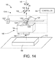
- the actuator assembly 104A includes a first actuator 120X configured to move the extruder body 164 in the x-direction 128, a second actuator 120Y configured to move the extruder body 164 in the y-direction 132, a third actuator 120Z configured to move the extruder body 164 in the z-direction 136, and a fourth actuator 120R configured to rotate the extruder body 164 about the rotational axis 140.
- the actuator assembly 104A includes one or more of the first, second, and third actuators 120X, 120Y, and 120Z, but does not include a fourth actuator 120R.
- the extruder assembly 108 includes an extruder body 160 and a reservoir 164, which is configured to store a quantity of build material.
- At least one extrusion opening 168 (not shown to scale in the view of FIG. 1 ) is defined at the bottom of the extruder body 160.
- the at least one extrusion opening 168 is operably connected to the reservoir 164 and is configured to extrude build material received from the reservoir 164 to form a build object 180 on the build platen 112.
- the at least one extrusion opening 168 is a single slot-shaped opening.
- the length of the slot-shaped extrusion opening 168 is between approximately 0.75 mm and approximately 6.4 mm and the width of the slot-shaped extrusion opening 168 is between approximately 0.2 mm and approximately 0.5 mm.
- the length of the slot-shaped extrusion opening 168 is approximately 1.2 mm and the width of the slot-shaped extrusion opening 168 is approximately 0.3 mm.
- the at least one extrusion opening 168 includes a plurality of slots or a plurality of smaller nozzles arranged in a line or in an array.
- the at least one extrusion opening is formed by another suitable opening or plurality of openings.
- the dimensions of the opening define an extrusion area of the single extrusion opening through which build material can be extruded.
- the dimensions of each opening define an area and the sum of the areas of the multiple extrusion openings define the extrusion area through which the material can be extruded.
- FIG. 2 illustrates a self-valving process 300 used to operate the three-dimensional object printer 100 to extrude build material to form a build object 180.
- the process is performing some task or function refers to a controller or general purpose processor executing programmed instructions stored in non-transitory computer readable storage media operatively connected to the controller or processor to manipulate data and operate one or more components in the system to perform the task or function.
- the controller 116 of the three-dimensional object printer 100 noted above can be configured with components and programmed instructions to provide a controller or processor that performs the process 300.
- the controller can be implemented with more than one processor and associated circuitry and components, each of which is configured to form one or more tasks or functions described herein.
- the process 300 begins with the controller 116 operating the actuator 120 to position the extruder body 160 such that a first portion 172 of the extrusion slot 168 is covered by an object 184 supported on the build platen 112, while a second portion 176 of the extrusion slot 168 is left open (block 304).
- the object 184 covering the first portion 172 is a previously extruded ribbon of build material forming a portion of the build object 180.
- the object covering the first portion may be a metal, wood, or plastic object around which or to which the build object is formed, for example a template or guide.
- the controller 116 operates the extruder assembly 108 to extrude build material through the second portion 176 of the at least one extrusion opening 168 (block 308).
- the controller 116 operates the actuator 120 to move the extruder assembly 108 along the object 184 into the page in the view of FIGS. 3 and 4 , so as to form a continuous ribbon 188 ( FIG. 4 ) of build material adjacent to the object 184 (block 312).
- the controller 116 is configured to adjust the flow rate of build material extruded by the extruder assembly 108 based upon the area of the open second portion 176.
- the controller 116 may be configured to operate the extruder assembly 108 to extrude the build material at a rate that is reduced from a maximum flow rate, which is used for extruding through the uncovered extrusion opening, by an amount that is proportional to the ratio of the covered first portion 172 to the total area of the at least one extrusion opening 168. For instance, if the covered first portion 172 is one third of the total area of the at least one extrusion opening 168, the flow rate of the extruded material would be reduced by one-third to two-thirds of the maximum flow rate.
- the strip 188 of build material has a width that is less than the width of the extrusion slot 168.
- the overall dimension of a given layer, for example layer 192, of the extruded build object 180 is not limited to an integer product of the width of the at least one extrusion opening 168, but instead can be formed in any desired width.
- the controller 116 is configured to operate the actuator 120 to move the extruder assembly 108 transversely to the direction in which the strip is formed, for example horizontally in the view of FIGS. 3 and 4 during the extrusion process, to vary the width of the strip 188 along its length.
- the process 300 is repeated to form multiple ribbons having width less than the width of the extrusion slot 168.
- the controller 116 is configured to form one or more additional ribbons adjacent to the ribbon 188, each of the additional ribbons having a width essentially equal to the width of the extrusion slot 168. Ribbons of build material are formed adjacent to one another so as to form a contiguous layer 192 of build material.
- the controller 116 is configured to form multiple contiguous layers of build material to form the build object 180.
- the configuration of the three-dimensional object printer 100 described above forms curved surfaces and fine features of the build object, while still being capable of forming wide ribbons.
- the printer 100 can form objects at high speeds, without sacrificing resolution of smaller features of the build object 180.
- the adjacent ribbons overlap with one another, reducing or eliminating gaps between adjacent ribbons, thereby improving overall strength of the build object 180.
- FIG. 5 illustrates another self-valving process 350 used to operate the three-dimensional object printer 100 to extrude build material to form a build object 180.
- the process is performing some task or function refers to a controller or general purpose processor executing programmed instructions stored in non-transitory computer readable storage media operatively connected to the controller or processor to manipulate data and operate one or more components in the system to perform the task or function.
- the controller 116 of the three-dimensional object printer 100 noted above can be configured with components and programmed instructions to provide a controller or processor that performs the process 350. Alternatively, the controller can be implemented with more than one processor and associated circuitry and components, each of which is configured to form one or more tasks or functions described herein.
- the process 350 begins with the controller 116 operating the extruder assembly 180 to extrude build material while operating the actuator 120 to move the extruder assembly to form a first ribbon 200 of build material (block 354).
- the first ribbon 200 is centered over a seam 204 between two adjacent ribbons 208, 212, which extend in the same direction as the first ribbon 200 of the layer 216 immediately below the first ribbon 200.
- the first ribbon 200 and an adjacent ribbon do not have form a common joint with the adjacent ribbons 208, 212 of the layer 216 immediately below the first ribbon 200.
- the overall strength of the build object 180 is improved.
- the first ribbon 200 may be centered offset from the seam 204, or may be aligned with the seam 204.
- the ribbons of the layer immediately below the first ribbon 200 are oriented transversely with respect to the first ribbon, for example perpendicularly with respect to the first ribbon (as illustrated for example by layers 256 and 260) or at an angle of 45 degrees with respect to the first ribbon.
- the controller 116 operates the actuator 120 to move the extruder assembly 108 to a position at which a first portion 220 of the extrusion opening 168 is covered by the first ribbon 200, while a second portion 224 of the extrusion opening 168 remains open, as illustrated in FIG. 6 (block 358).
- the outer edge of the build object 180 is formed.
- the controller 116 operates the actuator 120 to align the outer edge of the extrusion slot 168 with the outer edge of the previously extruded layers, for example the outer edge of the ribbon 208 of lower layer 216.
- the controller 116 then operates the extruder assembly 108 to extrude build material and simultaneously operates the actuator 120 to move the extruder assembly 108 so as to form a second ribbon 232 of build material adjacent to the first ribbon 200 and on top of the ribbon 208 of the lower layer 216, as illustrated in FIG. 7 (block 362).
- the second ribbon 232 forms the outer edge of the build object 180.
- the second ribbon may form a portion of the build object that is not at an outer edge and may, for example, be one of ribbons 236, 240, 244, 248. Forming intermediate ribbons overlapped with the adjacent ribbon reduces the gap present between adjacent ribbons, thereby improving the overall strength of the build object 180.
- additional ribbons of build material for example one or more of ribbons 236, 240, 244, 248, etc. may be formed between the formation of the first and second ribbons 200, 232.
- one or more of ribbons 236, 240, 244, 248, etc. may be formed before or after the formation of the first and second ribbons.
- the embodiment of FIGS. 5-7 is also capable of forming ribbons having fine features, while also providing for quicker formation of the build object. Moreover, since the outer edge of the build object is formed by ribbons whose opposite edges are staggered with respect to the adjacent layers, no common joint exists between adjacent layers (compare FIG. 4 with FIG. 7 ). As a result, no common break line occurs at the interior side of the ribbons formed at the outer edge of the build object 180, thereby further improving the overall structural strength of the build object 180.
- FIG. 8 illustrates one process 400 used to operate the three-dimensional object printer 100 in such a manner to form a build object 180.
- the process is performing some task or function refers to a controller or general purpose processor executing programmed instructions stored in non-transitory computer readable storage media operatively connected to the controller or processor to manipulate data and operate one or more components in the system to perform the task or function.
- the controller 116 of the three-dimensional object printer 100 noted above can be configured with components and programmed instructions to provide a controller or processor that performs the process 400.
- the controller can be implemented with more than one processor and associated circuitry and components, each of which is configured to form one or more tasks or functions described herein.
- the process 400 begins with the controller 116 operating the actuator 120 to rotate the extruder body 160 to align the width of the slot with the direction of travel for the first layer 440 ( FIG. 9 ) (block 404).
- the first direction is in the y-direction.
- the controller 116 determines the desired direction of travel based upon the digital model of the build object.
- the controller 116 then operates the actuator 120 to translate the extruder body 160 in the direction of travel while extruding material from the slot 168 to extrude ribbons 442, 444, 446, 448, 450 of build material to form the first layer 440 (block 408).
- the actuator 120 moves the extruder body 160 at a speed between approximately 5000 mm/min and 8000 mm/min during the extrusion processes. In another particular embodiment, the actuator moves the extruder body 160 at a speed of approximately 6000 mm/min during the extrusion processes.
- One or more of the ribbons 442, 444, 446, 448, 450 may be formed using the self-valving processes 300, 350 described above with reference to FIGS. 2-7 .
- the layers may be formed such that the lower layer 440 corresponds to the layer 256 in FIG. 7 , while the upper layer 472 corresponds to the layer 252 in FIG. 7 .
- the controller 116 is configured to operate the actuator 120 and extruder assembly 108 to produce the strips 442-450 by forming the center ribbon 442 first, and then forming the adjacent ribbons 444, 446, and finally forming the outer ribbons 448, 450 to improve adhesion between the ribbons 442-450 and thus improve the structural strength of the layer.
- the outer ribbons 448, 450 are formed using one of the self-valving processes 300, 350 to have a width less than the width of the other ribbons 442, 444, 446 so as to provide for the desired overall width and outer contour of the first layer 440.
- any one or more of the ribbons 442, 444, 446, 448, 450 are formed using the self-valving processes 300, 350 described above.
- the layers 442-450 are formed from left-to-right or right-to-left to increase layer forming speed.
- the strips 442-450 have different widths from one another.
- the outside strips 448, 450 may have a width that is half the width of the inner strips 442, 444, 446.
- the controller 116 operates the actuator 120 to rotate the extruder body 160 to align with the second direction (block 412).
- the second direction is aligned with the x-direction, orthogonal to the first direction.
- the controller 116 then operates the actuator 120 to translate the extruder body 160 while extruding material from the slot 168 to extrude ribbons 462, 464, 466, 468, 470 of build material, which form the second layer (block 416).
- One or more of the extruded ribbons 462, 464, 466, 468, 470 may be formed using the self-valving processes 300, 350 discussed above to form fine features and/or increase adhesion between adjacent ribbons.
- rotating the extruder body is not required in all embodiments.
- the extruder body 160 is not rotated to align the width prior to moving the extruder body 160 and extruding build material (block 408).
- the ribbons 442, 444, 446, 448, 450 may be formed with a width that is less than the width of the extrusion slot 168 in block 408.
- the extruder body 160 is not rotated to align the width of the slot prior to moving the extruder body 160 and extruding build material to form the second layer (block 416).
- the width of the ribbons 442, 444, 446, 448, 450 of the first layer 440 may be different from the ribbons 462, 464, 466, 468, 470 of the second layer 472.
- the controller 116 may operate the actuator 120 to rotate the extruder body 160 to align with a third direction and form another layer in the third direction, or the controller 116 may operate the actuator 120 to repeat the processing of block 400 to produce additional layers in the first and second directions. While FIGS. 9 and 10 illustrate the ribbons 442-450, 462-470 as being separated from one another to clearly show the alignment of the ribbons 442-450, 462-470 of the different layers 440, 460, respectively, the reader should appreciate that the ribbons 442-450, 462-470 are typically formed adjacent to or overlapping with one another so as to form a continuous layer of build material.
- FIG. 11 illustrates another process 500 used to operate the three-dimensional object printer 100 in such a manner to form a build object 180.
- the process is performing some task or function refers to a controller or general purpose processor executing programmed instructions stored in non-transitory computer readable storage media operatively connected to the controller or processor to manipulate data and operate one or more components in the system to perform the task or function.
- the controller 116 of the three-dimensional object printer 100 noted above can be configured with components and programmed instructions to provide a controller or processor that performs the process 500.
- the controller can be implemented with more than one processor, associated circuitry, and components, each of which is configured to form one or more tasks or functions described herein.
- the process 500 begins with the controller 116 operating the extruder body 160 to extrude build material and the actuator 120 to move the extruder body 160 to form a first layer of ribbons oriented in a first direction (block 504).
- the first layer may be formed in a similar manner as the first layer 440 discussed above with regard to FIGS. 8-10 .
- the controller 116 operates the extruder body 160 to extrude build material and the actuator 120 to move the extruder body 160 to form a second layer of ribbons oriented in the first direction (block 508).
- the second layer is formed offset from the first layer, such that the ribbons of the first and second layers do not have common joints. Note that in some embodiments more than two contiguous ribbons may be printed in the same direction with any ribbon being either in a different direction or being in the same direction is offset and not having common joints with its neighbors.
- the process 500 proceeds with the controller 116 the extruder body 160 to extrude build material and the actuator 120 to move the extruder body 160 to form a third layer of ribbons oriented in a second direction (block 504).
- the third layer may be formed in a similar manner as the second layer 472 discussed above with regard to FIGS. 8-10 , for example, having ribbons oriented perpendicularly with respect to the first and second layers.
- the controller 116 operates the extruder body 160 to extrude build material and the actuator 120 to move the extruder body 160 to form a fourth layer of ribbons oriented in the second direction (block 508).
- the fourth layer is formed offset from the third layer, such that the ribbons of the first and second layers do not have common joints.
- the layers 260, 256, 252, and 216 shown in FIGS. 6 and 7 may correspond to the first, second, third, and fourth layers, respectively, formed according to the process 500. As shown in FIGS. 6 and 7 , the third and fourth layers 252, 216 are offset from one another, and the first and second layers 260, 256 are offset from one another in a similar manner, though the offset is not visible in FIGS. 6 and 7 since the ribbons of the layers 260, 256 are formed horizontally in the figures.
- the controller 116 is configured to operate the actuator 120, or, in embodiments having separate translational and rotational actuators, both the translational and rotational actuators, to rotate and translate the extruder body 160 at the same time ( FIG. 11 ).
- the actuator 120 or, in embodiments having separate translational and rotational actuators, both the translational and rotational actuators, to rotate and translate the extruder body 160 at the same time ( FIG. 11 ).
- the outer edge of the slot 168 defines the outer edge of the curve, while the inner edge of the slot 168 forms the inner edge of the curve. Since the outside edge of the extrusion slot 168 travels a greater distance than the inside edge of the slot 168, an adjustment is required to the extrusion to account for the different travel distances of the inner and outer edges.
- the rate of extrusion should be proportional to ⁇ r 2 /(2 ⁇ r ), or r /2.
- FIG. 12 illustrates a curve of the extrusion factor plotted against the ratio of the radius to extrusion width, or slot width.
Landscapes
- Engineering & Computer Science (AREA)
- Chemical & Material Sciences (AREA)
- Materials Engineering (AREA)
- Manufacturing & Machinery (AREA)
- Mechanical Engineering (AREA)
- Physics & Mathematics (AREA)
- Optics & Photonics (AREA)
- Health & Medical Sciences (AREA)
- Clinical Laboratory Science (AREA)
Abstract
Description
- The system and method disclosed in this document relate to printers that produce three-dimensional objects and, more particularly, to extruder assemblies for such printers.
- Digital three-dimensional manufacturing, also known as digital additive manufacturing, is a process of making a three-dimensional solid object of virtually any shape from a digital model. Three-dimensional object printing is an additive process in which one or more extruder or ejector assemblies form successive layers of material, for example thermoplastics such as acrylonitrile butadiene styrene ("ABS") or polylactic acid ("PLA"), on a substrate in different shapes. In some conventional three-dimensional object printers, the extruders are similar to printheads in document printers. Such extruders include an array of extruders that emit a continuous stream of material to form layers, rather than an array of ejectors that eject drops of material.
- In other known three-dimensional object printers, the extruder assembly includes a single nozzle configured to extrude the build material to form layers for production of a printed object. The nozzle is generally configured as a small circular hole that emits a continuous filament of build material. The filaments are laid down in adjacent strips layer by layer to form the three-dimensional part.
- In such an extruder assembly, the printed object should be formed quickly and accurately. The size of the nozzle determines both the minimum resolution of the part and the speed at which the object can be formed. An extruder having a larger nozzle can form the object more quickly, but the resolution is reduced since the formation of the adjacent strips requires that the width of a layer be equal to an integer multiple of the nozzle width. An extruder having a smaller diameter nozzle, on the other hand, can be used to form smaller details, but, since the volume extruded in each pass is small the product requires more time to produce, sometimes on the order of hours or days. Thus, in conventional three-dimensional object printers, the size of the nozzle presents a trade-off between build speed and build resolution.
- One solution to this problem is to use an extruder assembly having a large nozzle for larger objects and a small nozzle for detail formation. However, such an extrusion assembly is expensive since connections, valves, and control circuitry are required for each of the nozzles. Another solution has been to build parts that are mostly hollow inside using small nozzle extruder assemblies. While building hollow parts reduces the time necessary to produce the object, the structural strength of the object is severely reduced, limiting the utility of the hollow object.
- Accordingly, improvements in systems and methods for forming three-dimensional objects with printers that include extruder assemblies so the objects have greater detail, increased structural strength, and reduced production time would be beneficial.
- A method of operating an extruder assembly to form a three-dimensional build object forms a build object quickly, with enhanced feature resolution, and with increased structural strength. The method includes positioning with at least one actuator an extruder having at least one opening defining an extrusion area through which material can be extruded through the at least one opening. The extruder is positioned to cover a first portion of the extrusion area with a portion of an object supported on a build platen and to leave open a second portion of the extrusion area. The method further includes extruding a first continuous ribbon of build material adjacent to the object through the second portion of the extrusion area while moving the extruder along the object with the at least one actuator.
- In another embodiment, an extruder assembly for a three-dimensional object printing system comprises an extruder, at least one actuator, and a controller. The extruder includes at least one opening configured to extrude a continuous ribbon of material, and the at least one opening defines an extrusion area through which material can be extruded through the at least one opening. The at least one actuator is operatively connected to the extruder and is configured to move the extruder in a horizontal plane. The controller is operably connected to the extruder, the at least one actuator, and a memory. The controller is configured to execute program instructions stored in the memory to operate the at least one actuator to position the extruder to cover a first portion of the extrusion area by a portion of an object supported on a build platen and to leave open a second portion of the extrusion area, and to operate the at least one actuator to move the extruder along the object and operate the extruder to extrude build material through the second portion of the extrusion area while operating the at least one actuator to move the extruder to extrude a first continuous ribbon of build material adjacent to the object.
- The foregoing aspects and other features of a printer having extruders and a method for operating a printer having extruders are explained in the following description, taken in connection with the accompanying drawings.
-
FIG. 1 is a schematic illustration of a three-dimensional object printer having an extruder assembly. -
FIG. 2 illustrates a method of forming a ribbon of build material using a self-valving process during the production of a build object. -
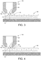
FIG. 3 illustrates a side partial cross-sectional view of the extruder body for the 3D object printer ofFIG. 1 forming a ribbon of build material using the self-valving process ofFIG. 2 . -
FIG. 4 illustrates another side partial cross-sectional view of the extruder body for the 3D object printer ofFIG. 1 forming the ribbon of build material using the self-valving process ofFIG. 2 . -
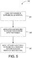
FIG. 5 illustrates a method of forming a ribbon of build material using a self-valving process during the production of a build object. -
FIG. 6 illustrates a side partial cross-sectional view of the extruder body for the 3D object printer ofFIG. 1 forming a ribbon of build material using the self-valving process ofFIG. 4 . -
FIG. 7 illustrates another side partial cross-sectional view of the extruder body for the 3D object printer ofFIG. 1 forming the ribbon of build material using the self-valving process ofFIG. 4 . -
FIG. 8 illustrates a method of operating the 3D object printer ofFIG. 1 to produce a build object. -
FIG. 9 illustrates a top view of a first layer produced by the 3D object printer ofFIG. 1 according to the method ofFIG. 10 . -
FIG. 10 illustrates a top view of the first layer ofFIG. 11 and a second layer produced by the 3D object printer ofFIG. 1 according to the method ofFIG. 10 . -
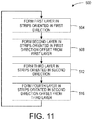
FIG. 11 illustrates a method of operating the 3D object printer ofFIG. 1 to produce a build object. -
FIG. 12 illustrates a top partial schematic view of the extruder body ofFIG. 1 simultaneously translating and rotating so as to form a curved feature. -
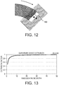
FIG. 13 illustrates a graph of extrusion factor against the ratio of radius to extrusion width for the production of curved features using the extrusion slot ofFIG. 1 . -
FIG. 14 is a schematic illustration of a three-dimensional object printer having an extruder assembly with an extrusion slot and including a separate actuator configured to move the extruder body in each of the x-, y-, z-, and rotational directions. - For a general understanding of the environment for the system and method disclosed herein as well as the details for the system and method, reference is made to the drawings. In the drawings, like reference numerals have been used throughout to designate like elements.
-
FIG. 1 illustrates a three-dimensional object printer 100. The three-dimensional object printer 100 includes anactuator assembly 104, anextruder assembly 108, abuild platen 112, and acontroller 116. Theactuator assembly 104 includes at least oneactuator 120 and a pair ofrails 124 attached to a support frame (not shown). Therails 124 are configured to support theactuator 120 and theextruder assembly 108 to enable theactuator 120 to translate theextruder assembly 108 along anx-axis 128, a y-axis 132, and a z-axis 136, and rotate theextruder assembly 108 about arotational axis 140, which is parallel to the z-axis 136 in the illustrated embodiment. - In the embodiment of
FIG. 1 , theactuator assembly 104 includes asingle actuator 120 configured to translate theextruder assembly 108 in the x-, y-, and z-axes extruder assembly 108 about therotational axis 140. In another embodiment, theactuator assembly 104 includes a first actuator configured to move theextruder assembly 108 in the x-, y-, and z-axes extruder assembly 108 about therotational axis 140. In further embodiments, theactuator 120 may be configured to translate theextruder assembly 108 in one or more of the x-, y-, and z-axes extruder assembly 108. - In yet another embodiment, illustrated in
FIG. 13 , theactuator assembly 104A includes afirst actuator 120X configured to move theextruder body 164 in thex-direction 128, asecond actuator 120Y configured to move theextruder body 164 in the y-direction 132, a third actuator 120Z configured to move theextruder body 164 in the z-direction 136, and afourth actuator 120R configured to rotate theextruder body 164 about therotational axis 140. In another embodiment, theactuator assembly 104A includes one or more of the first, second, andthird actuators fourth actuator 120R. - Referring back to
FIG. 1 , theextruder assembly 108 includes anextruder body 160 and areservoir 164, which is configured to store a quantity of build material. At least one extrusion opening 168 (not shown to scale in the view ofFIG. 1 ) is defined at the bottom of theextruder body 160. The at least oneextrusion opening 168 is operably connected to thereservoir 164 and is configured to extrude build material received from thereservoir 164 to form abuild object 180 on thebuild platen 112. - In the embodiment illustrated in
FIG. 1 , the at least one extrusion opening 168 is a single slot-shaped opening. In one embodiment, the length of the slot-shaped extrusion opening 168 is between approximately 0.75 mm and approximately 6.4 mm and the width of the slot-shaped extrusion opening 168 is between approximately 0.2 mm and approximately 0.5 mm. In another specific embodiment, the length of the slot-shaped extrusion opening 168 is approximately 1.2 mm and the width of the slot-shaped extrusion opening 168 is approximately 0.3 mm. In other embodiments, the at least one extrusion opening 168 includes a plurality of slots or a plurality of smaller nozzles arranged in a line or in an array. In still other embodiments, the at least one extrusion opening is formed by another suitable opening or plurality of openings. In embodiments having a single extrusion opening, the dimensions of the opening define an extrusion area of the single extrusion opening through which build material can be extruded. In embodiments having more than one extrusion opening, the dimensions of each opening define an area and the sum of the areas of the multiple extrusion openings define the extrusion area through which the material can be extruded. -
FIG. 2 illustrates a self-valving process 300 used to operate the three-dimensional object printer 100 to extrude build material to form abuild object 180. Statements that the process is performing some task or function refers to a controller or general purpose processor executing programmed instructions stored in non-transitory computer readable storage media operatively connected to the controller or processor to manipulate data and operate one or more components in the system to perform the task or function. Thecontroller 116 of the three-dimensional object printer 100 noted above can be configured with components and programmed instructions to provide a controller or processor that performs theprocess 300. Alternatively, the controller can be implemented with more than one processor and associated circuitry and components, each of which is configured to form one or more tasks or functions described herein. - With reference to
FIGS. 2-4 , theprocess 300 begins with thecontroller 116 operating theactuator 120 to position theextruder body 160 such that afirst portion 172 of theextrusion slot 168 is covered by anobject 184 supported on thebuild platen 112, while asecond portion 176 of theextrusion slot 168 is left open (block 304). In the illustrated embodiment, theobject 184 covering thefirst portion 172 is a previously extruded ribbon of build material forming a portion of thebuild object 180. In other embodiments, the object covering the first portion may be a metal, wood, or plastic object around which or to which the build object is formed, for example a template or guide. - Once the
extruder body 160 is positioned, thecontroller 116 operates theextruder assembly 108 to extrude build material through thesecond portion 176 of the at least one extrusion opening 168 (block 308). As theextruder assembly 108 is operated to extrude, thecontroller 116 operates theactuator 120 to move theextruder assembly 108 along theobject 184 into the page in the view ofFIGS. 3 and 4 , so as to form a continuous ribbon 188 (FIG. 4 ) of build material adjacent to the object 184 (block 312). - In some embodiments, the
controller 116 is configured to adjust the flow rate of build material extruded by theextruder assembly 108 based upon the area of the opensecond portion 176. For example, thecontroller 116 may be configured to operate theextruder assembly 108 to extrude the build material at a rate that is reduced from a maximum flow rate, which is used for extruding through the uncovered extrusion opening, by an amount that is proportional to the ratio of the coveredfirst portion 172 to the total area of the at least oneextrusion opening 168. For instance, if the coveredfirst portion 172 is one third of the total area of the at least oneextrusion opening 168, the flow rate of the extruded material would be reduced by one-third to two-thirds of the maximum flow rate. - As can be seen in
FIG. 4 , thestrip 188 of build material has a width that is less than the width of theextrusion slot 168. Thus, the overall dimension of a given layer, forexample layer 192, of the extrudedbuild object 180 is not limited to an integer product of the width of the at least oneextrusion opening 168, but instead can be formed in any desired width. Moreover, in some embodiments, thecontroller 116 is configured to operate theactuator 120 to move theextruder assembly 108 transversely to the direction in which the strip is formed, for example horizontally in the view ofFIGS. 3 and 4 during the extrusion process, to vary the width of thestrip 188 along its length. - In some embodiments, the
process 300 is repeated to form multiple ribbons having width less than the width of theextrusion slot 168. In other embodiments upon completion of theprocess 300, thecontroller 116 is configured to form one or more additional ribbons adjacent to theribbon 188, each of the additional ribbons having a width essentially equal to the width of theextrusion slot 168. Ribbons of build material are formed adjacent to one another so as to form acontiguous layer 192 of build material. In some embodiments, thecontroller 116 is configured to form multiple contiguous layers of build material to form thebuild object 180. - The configuration of the three-
dimensional object printer 100 described above forms curved surfaces and fine features of the build object, while still being capable of forming wide ribbons. As a result, theprinter 100 can form objects at high speeds, without sacrificing resolution of smaller features of thebuild object 180. Furthermore, in embodiments in which the object covering thefirst portion 172 of theextrusion slot 168 is a previously extruded ribbon, the adjacent ribbons overlap with one another, reducing or eliminating gaps between adjacent ribbons, thereby improving overall strength of thebuild object 180. -
FIG. 5 illustrates another self-valving process 350 used to operate the three-dimensional object printer 100 to extrude build material to form abuild object 180. Statements that the process is performing some task or function refers to a controller or general purpose processor executing programmed instructions stored in non-transitory computer readable storage media operatively connected to the controller or processor to manipulate data and operate one or more components in the system to perform the task or function. Thecontroller 116 of the three-dimensional object printer 100 noted above can be configured with components and programmed instructions to provide a controller or processor that performs theprocess 350. Alternatively, the controller can be implemented with more than one processor and associated circuitry and components, each of which is configured to form one or more tasks or functions described herein. - Referring to
FIGS. 5-7 , theprocess 350 begins with thecontroller 116 operating theextruder assembly 180 to extrude build material while operating theactuator 120 to move the extruder assembly to form afirst ribbon 200 of build material (block 354). In the illustrated embodiment, thefirst ribbon 200 is centered over aseam 204 between twoadjacent ribbons first ribbon 200 of thelayer 216 immediately below thefirst ribbon 200. Thefirst ribbon 200 and an adjacent ribbon do not have form a common joint with theadjacent ribbons layer 216 immediately below thefirst ribbon 200. As a result of the offset, the overall strength of thebuild object 180 is improved. In other embodiments, however, thefirst ribbon 200 may be centered offset from theseam 204, or may be aligned with theseam 204. In further embodiments, the ribbons of the layer immediately below thefirst ribbon 200 are oriented transversely with respect to the first ribbon, for example perpendicularly with respect to the first ribbon (as illustrated for example bylayers 256 and 260) or at an angle of 45 degrees with respect to the first ribbon. - Once the
first ribbon 200 is formed, thecontroller 116 operates theactuator 120 to move theextruder assembly 108 to a position at which afirst portion 220 of theextrusion opening 168 is covered by thefirst ribbon 200, while asecond portion 224 of theextrusion opening 168 remains open, as illustrated inFIG. 6 (block 358). In the embodiment illustrated inFIG. 6 , the outer edge of thebuild object 180 is formed. Thus, thecontroller 116 operates theactuator 120 to align the outer edge of theextrusion slot 168 with the outer edge of the previously extruded layers, for example the outer edge of theribbon 208 oflower layer 216. - The
controller 116 then operates theextruder assembly 108 to extrude build material and simultaneously operates theactuator 120 to move theextruder assembly 108 so as to form a second ribbon 232 of build material adjacent to thefirst ribbon 200 and on top of theribbon 208 of thelower layer 216, as illustrated inFIG. 7 (block 362). In the illustration ofFIG. 7 , the second ribbon 232 forms the outer edge of thebuild object 180. In other embodiments, the second ribbon may form a portion of the build object that is not at an outer edge and may, for example, be one ofribbons build object 180. - The reader should appreciate that in some embodiments, additional ribbons of build material, for example one or more of
ribbons second ribbons 200, 232. In other embodiments, one or more ofribbons - As in the embodiment discussed above with respect to
FIGS. 2-4 , the embodiment ofFIGS. 5-7 is also capable of forming ribbons having fine features, while also providing for quicker formation of the build object. Moreover, since the outer edge of the build object is formed by ribbons whose opposite edges are staggered with respect to the adjacent layers, no common joint exists between adjacent layers (compareFIG. 4 withFIG. 7 ). As a result, no common break line occurs at the interior side of the ribbons formed at the outer edge of thebuild object 180, thereby further improving the overall structural strength of thebuild object 180. - In some embodiments, the controller is configured to operate the
actuator 120 to form the ribbons of adjacent layers in different directions with respect to one another.FIG. 8 illustrates oneprocess 400 used to operate the three-dimensional object printer 100 in such a manner to form abuild object 180. Statements that the process is performing some task or function refers to a controller or general purpose processor executing programmed instructions stored in non-transitory computer readable storage media operatively connected to the controller or processor to manipulate data and operate one or more components in the system to perform the task or function. Thecontroller 116 of the three-dimensional object printer 100 noted above can be configured with components and programmed instructions to provide a controller or processor that performs theprocess 400. Alternatively, the controller can be implemented with more than one processor and associated circuitry and components, each of which is configured to form one or more tasks or functions described herein. - With reference to
FIGS. 8-10 , theprocess 400 begins with thecontroller 116 operating theactuator 120 to rotate theextruder body 160 to align the width of the slot with the direction of travel for the first layer 440 (FIG. 9 ) (block 404). In the embodiment illustrated inFIG. 9 , for example, the first direction is in the y-direction. In some embodiments, thecontroller 116 determines the desired direction of travel based upon the digital model of the build object. Thecontroller 116 then operates theactuator 120 to translate theextruder body 160 in the direction of travel while extruding material from theslot 168 to extruderibbons - In one particular embodiment, the
actuator 120 moves theextruder body 160 at a speed between approximately 5000 mm/min and 8000 mm/min during the extrusion processes. In another particular embodiment, the actuator moves theextruder body 160 at a speed of approximately 6000 mm/min during the extrusion processes. One or more of theribbons valving processes FIGS. 2-7 . In particular, the layers may be formed such that thelower layer 440 corresponds to thelayer 256 inFIG. 7 , while theupper layer 472 corresponds to thelayer 252 inFIG. 7 . - In some embodiments of the three-dimensional object printer, the
controller 116 is configured to operate theactuator 120 andextruder assembly 108 to produce the strips 442-450 by forming thecenter ribbon 442 first, and then forming theadjacent ribbons outer ribbons outer ribbons valving processes other ribbons first layer 440. In another embodiment, any one or more of theribbons valving processes outside strips inner strips - Once the
first layer 440 is complete, thecontroller 116 operates theactuator 120 to rotate theextruder body 160 to align with the second direction (block 412). In the illustrated embodiment, the second direction is aligned with the x-direction, orthogonal to the first direction. However, the reader should appreciate that the angle between the first and second directions can be other desired angles depending on the characteristics of the build object. Thecontroller 116 then operates theactuator 120 to translate theextruder body 160 while extruding material from theslot 168 to extruderibbons extruded ribbons valving processes - The reader should appreciate that rotating the extruder body (blocks 404, 412) is not required in all embodiments. For example, in some embodiments of the process, the
extruder body 160 is not rotated to align the width prior to moving theextruder body 160 and extruding build material (block 408). Instead, theribbons extrusion slot 168 inblock 408. Additionally or alternatively, in other embodiments, theextruder body 160 is not rotated to align the width of the slot prior to moving theextruder body 160 and extruding build material to form the second layer (block 416). As a result, in some of the above embodiments, the width of theribbons first layer 440 may be different from theribbons second layer 472. - If additional layers remain to be printed, the
controller 116 may operate theactuator 120 to rotate theextruder body 160 to align with a third direction and form another layer in the third direction, or thecontroller 116 may operate theactuator 120 to repeat the processing ofblock 400 to produce additional layers in the first and second directions. WhileFIGS. 9 and 10 illustrate the ribbons 442-450, 462-470 as being separated from one another to clearly show the alignment of the ribbons 442-450, 462-470 of thedifferent layers 440, 460, respectively, the reader should appreciate that the ribbons 442-450, 462-470 are typically formed adjacent to or overlapping with one another so as to form a continuous layer of build material. -
FIG. 11 illustrates anotherprocess 500 used to operate the three-dimensional object printer 100 in such a manner to form abuild object 180. Statements that the process is performing some task or function refers to a controller or general purpose processor executing programmed instructions stored in non-transitory computer readable storage media operatively connected to the controller or processor to manipulate data and operate one or more components in the system to perform the task or function. Thecontroller 116 of the three-dimensional object printer 100 noted above can be configured with components and programmed instructions to provide a controller or processor that performs theprocess 500. Alternatively, the controller can be implemented with more than one processor, associated circuitry, and components, each of which is configured to form one or more tasks or functions described herein. - The
process 500 begins with thecontroller 116 operating theextruder body 160 to extrude build material and theactuator 120 to move theextruder body 160 to form a first layer of ribbons oriented in a first direction (block 504). The first layer may be formed in a similar manner as thefirst layer 440 discussed above with regard toFIGS. 8-10 . Next, thecontroller 116 operates theextruder body 160 to extrude build material and theactuator 120 to move theextruder body 160 to form a second layer of ribbons oriented in the first direction (block 508). The second layer is formed offset from the first layer, such that the ribbons of the first and second layers do not have common joints. Note that in some embodiments more than two contiguous ribbons may be printed in the same direction with any ribbon being either in a different direction or being in the same direction is offset and not having common joints with its neighbors. - The
process 500 proceeds with thecontroller 116 theextruder body 160 to extrude build material and theactuator 120 to move theextruder body 160 to form a third layer of ribbons oriented in a second direction (block 504). The third layer may be formed in a similar manner as thesecond layer 472 discussed above with regard toFIGS. 8-10 , for example, having ribbons oriented perpendicularly with respect to the first and second layers. Next, thecontroller 116 operates theextruder body 160 to extrude build material and theactuator 120 to move theextruder body 160 to form a fourth layer of ribbons oriented in the second direction (block 508). The fourth layer is formed offset from the third layer, such that the ribbons of the first and second layers do not have common joints. - The
layers FIGS. 6 and 7 may correspond to the first, second, third, and fourth layers, respectively, formed according to theprocess 500. As shown inFIGS. 6 and 7 , the third andfourth layers second layers FIGS. 6 and 7 since the ribbons of thelayers - In order to form curved details, the
controller 116 is configured to operate theactuator 120, or, in embodiments having separate translational and rotational actuators, both the translational and rotational actuators, to rotate and translate theextruder body 160 at the same time (FIG. 11 ). As theextruder body 160 and theslot 168 rotate and translate, the outer edge of theslot 168 defines the outer edge of the curve, while the inner edge of theslot 168 forms the inner edge of the curve. Since the outside edge of theextrusion slot 168 travels a greater distance than the inside edge of theslot 168, an adjustment is required to the extrusion to account for the different travel distances of the inner and outer edges. In particular, when the radius of the curve is relatively small compared to the width of theslot 168, the quantity of build material extruded must be adjusted. As an example, extruding a small circle having a radius equal to the width of the slot (r) extrudes an area equal to πr 2, while the outside edge travels a linear distance of 2πr. Thus, the rate of extrusion should be proportional to πr 2/(2πr), or r/2. On the other hand, for a very large radius circle (R), the difference between the distances traveled by the inner and outer edges of theextrusion slot 168 are minimal, and the extrusion rate is proportional to the area printed (2πrR) divided by the path length (2πR), which is equal to r, or the slot width in this example.FIG. 12 illustrates a curve of the extrusion factor plotted against the ratio of the radius to extrusion width, or slot width. - It will be appreciated that variants of the above-disclosed and other features and functions, or alternatives thereof, may be desirably combined into many other different systems, applications or methods. Various presently unforeseen or unanticipated alternatives, modifications, variations, or improvements therein may be subsequently made by those skilled in the art, which are also intended to be encompassed by the following claims.
Claims (10)
- A method of operating an extruder assembly to form a three-dimensional build object comprising:positioning with at least one actuator an extruder having at least one opening that defines an extrusion area through which material can be extruded from the at least one opening, the extruder being positioned to cover a first portion of the extrusion area with a portion of an object supported on a build platen and to leave open a second portion of the extrusion area; andextruding a first continuous ribbon of build material adjacent to the object through the second portion of the extrusion area while moving the extruder along the object with the at least one actuator.
- The method of claim 1, the forming of the first ribbon further comprising:extruding the build material through the second portion of the extrusion area at a flow rate that is based on an area of the second portion of the extrusion area.
- The method of claim 1 further comprising:extruding a second continuous ribbon of build material through the at least one opening while moving the extruder with the at least one actuator before extruding the first continuous ribbon of build material through the second portion of the extrusion area;the positioning of the extruder including positioning the extruder to cover the first portion of the extrusion area with the second continuous ribbon; andthe first ribbon of build material is extruded adjacent to the second ribbon of build material.
- The method of claim 3 wherein the first and second ribbons form a contiguous portion of a first layer of the build object.
- The method of claim 4 wherein one of the first and second ribbons forms an outermost edge of the first layer.
- An extruder assembly for a three-dimensional object printing system comprising:an extruder having at least one opening configured to extrude a continuous ribbon of material, the at least one opening defining an extrusion area through which material can be extruded from the at least one opening;at least one actuator operatively connected to the extruder, the at least one actuator being configured to move the extruder in a horizontal plane; anda controller operably connected to the extruder, the at least one actuator, and a memory, the controller being configured to execute program instructions stored in the memory to:operate the at least one actuator to position the extruder to cover a first portion of the extrusion area by a portion of an object supported on a build platen and to leave open a second portion of the extrusion area; andoperate the at least one actuator to move the extruder along the object and operate the extruder to extrude build material through the second portion of the extrusion area while operating the at least one actuator to move the extruder to extrude a first continuous ribbon of build material adjacent to the object.
- The extruder assembly of claim 6, the controller being further configured to execute the program instructions to operate the extruder to extrude the build material through the second portion of the extrusion area at a flow rate that is based on an area of the second portion of the extrusion area.
- The extruder assembly of claim 6, the controller being further configured to execute the program instructions to:operate the extruder to extrude the build material through the at least one opening while operating the at least one actuator to move the extruder to extrude a second continuous ribbon of build material before operating the extruder and the at least one actuator to extrude the first continuous ribbon of build material;the operating of the at least one actuator to position the extruder including positioning of the extruder to cover the first portion of the extrusion area with the second ribbon; andthe operating of the extruder and the at least one actuator to extrude the first continuous ribbon of build material including operating the at least one actuator to move the extruder along the second continuous ribbon to extrude the first ribbon adjacent to the second ribbon.
- The extruder assembly of claim 8, the controller being further configured to execute the program instructions to operate the extruder and the at least one actuator to extrude the first and second continuous ribbons as a contiguous first layer of the build object.
- The extruder assembly of claim 9, the controller being further configured to execute the program instructions to operate the extruder and the at least one actuator to extrude one of the first and second continuous ribbons at an outermost edge of the first layer.
Applications Claiming Priority (1)
| Application Number | Priority Date | Filing Date | Title |
|---|---|---|---|
| US15/210,620 US9993964B2 (en) | 2016-07-14 | 2016-07-14 | Method and system for producing three-dimensional build objects |
Publications (2)
| Publication Number | Publication Date |
|---|---|
| EP3269527A1 true EP3269527A1 (en) | 2018-01-17 |
| EP3269527B1 EP3269527B1 (en) | 2019-03-20 |
Family
ID=59227552
Family Applications (1)
| Application Number | Title | Priority Date | Filing Date |
|---|---|---|---|
| EP17177869.9A Not-in-force EP3269527B1 (en) | 2016-07-14 | 2017-06-26 | Method and system for producing three-dimensional build objects |
Country Status (4)
| Country | Link |
|---|---|
| US (1) | US9993964B2 (en) |
| EP (1) | EP3269527B1 (en) |
| JP (1) | JP6771431B2 (en) |
| CN (1) | CN107618178B (en) |
Cited By (2)
| Publication number | Priority date | Publication date | Assignee | Title |
|---|---|---|---|---|
| EP3804962A1 (en) * | 2019-10-07 | 2021-04-14 | SHPP Global Technologies B.V. | Additive manufacturing method |
| EP4094924A1 (en) * | 2021-05-25 | 2022-11-30 | Mark Saberton | 3d printing bead configuration |
Families Citing this family (11)
| Publication number | Priority date | Publication date | Assignee | Title |
|---|---|---|---|---|
| US10335991B2 (en) | 2015-12-08 | 2019-07-02 | Xerox Corporation | System and method for operation of multi-nozzle extrusion printheads in three-dimensional object printers |
| US20170320267A1 (en) * | 2016-05-03 | 2017-11-09 | Ut-Battelle, Llc | Variable Width Deposition for Additive Manufacturing with Orientable Nozzle |
| JP7135409B2 (en) * | 2018-04-27 | 2022-09-13 | セイコーエプソン株式会社 | Three-dimensional modeling apparatus and three-dimensional model manufacturing method |
| JP6734517B2 (en) * | 2018-06-25 | 2020-08-05 | Kjケミカルズ株式会社 | 3D modeling apparatus and 3D modeling method using different materials |
| US11040487B2 (en) | 2019-03-27 | 2021-06-22 | Xerox Corporation | Method for operating an extruder in a three-dimensional (3D) object printer to improve layer formation |
| US20230249394A1 (en) * | 2022-02-08 | 2023-08-10 | Mark Saberton | Additive manufacturing process |
| JP7193742B2 (en) * | 2020-05-07 | 2022-12-21 | ケイワイ株式会社 | 3D modeling data generation program and 3D object manufacturing method |
| US11338523B2 (en) | 2020-06-10 | 2022-05-24 | Xerox Corporation | System and method for operating a multi-nozzle extruder during additive manufacturing |
| US11731366B2 (en) | 2020-07-31 | 2023-08-22 | Xerox Corporation | Method and system for operating a metal drop ejecting three-dimensional (3D) object printer to form electrical circuits on substrates |
| US11737216B2 (en) * | 2021-01-22 | 2023-08-22 | Xerox Corporation | Metal drop ejecting three-dimensional (3D) object printer |
| US11890674B2 (en) | 2022-03-01 | 2024-02-06 | Xerox Corporation | Metal drop ejecting three-dimensional (3D) object printer and method of operation for forming support structures in 3D metal objects |
Citations (3)
| Publication number | Priority date | Publication date | Assignee | Title |
|---|---|---|---|---|
| US20110081453A1 (en) * | 2009-10-05 | 2011-04-07 | T.F.H. Publications, Inc. | 3-D Continuous Shaping Of Edible-Based Extrudates |
| CN204622625U (en) * | 2015-05-23 | 2015-09-09 | 邓小荣 | A kind of adjustable three-dimensional printer shower nozzle extruding flow |
| WO2016061060A1 (en) * | 2014-10-16 | 2016-04-21 | Dow Global Technologies Llc | Method for additive manufacturing |
Family Cites Families (13)
| Publication number | Priority date | Publication date | Assignee | Title |
|---|---|---|---|---|
| US7555357B2 (en) * | 2006-01-31 | 2009-06-30 | Stratasys, Inc. | Method for building three-dimensional objects with extrusion-based layered deposition systems |
| US8439665B2 (en) * | 2009-09-30 | 2013-05-14 | Stratasys, Inc. | Ribbon liquefier for use in extrusion-based digital manufacturing systems |
| GB201118807D0 (en) | 2011-11-01 | 2011-12-14 | Univ Loughborough | Method and apparatus |
| US9511543B2 (en) | 2012-08-29 | 2016-12-06 | Cc3D Llc | Method and apparatus for continuous composite three-dimensional printing |
| CA3121870A1 (en) | 2013-03-22 | 2014-09-25 | Markforged, Inc. | Three dimensional printing |
| US9186848B2 (en) | 2013-03-22 | 2015-11-17 | Markforged, Inc. | Three dimensional printing of composite reinforced structures |
| CN105579220B (en) * | 2013-07-17 | 2017-09-08 | 马克弗盖德公司 | Device for Additive Manufacturing of Fiber Reinforcement |
| TWI596000B (en) * | 2013-12-13 | 2017-08-21 | 三緯國際立體列印科技股份有限公司 | Three-dimensional printing apparatus and printing head module |
| JP2017528340A (en) * | 2014-07-22 | 2017-09-28 | ストラタシス,インコーポレイテッド | Geared liquefaction assembly for additive manufacturing system and method of use thereof |
| US9073366B1 (en) * | 2014-07-25 | 2015-07-07 | Xyzprinting, Inc. | Rotational printing head module having muti-cartridge |
| US10766802B2 (en) * | 2014-11-29 | 2020-09-08 | National Tsing Hua University | Flexible 3D freeform techniques |
| CN205112415U (en) * | 2015-11-06 | 2016-03-30 | 珠海天威飞马打印耗材有限公司 | Three -dimensional printer |
| US10150239B2 (en) * | 2015-12-29 | 2018-12-11 | Western Digital Technologies, Inc. | Extruder for three-dimensional additive printer |
-
2016
- 2016-07-14 US US15/210,620 patent/US9993964B2/en active Active
-
2017
- 2017-06-26 CN CN201710497272.0A patent/CN107618178B/en not_active Expired - Fee Related
- 2017-06-26 EP EP17177869.9A patent/EP3269527B1/en not_active Not-in-force
- 2017-06-27 JP JP2017125110A patent/JP6771431B2/en not_active Expired - Fee Related
Patent Citations (3)
| Publication number | Priority date | Publication date | Assignee | Title |
|---|---|---|---|---|
| US20110081453A1 (en) * | 2009-10-05 | 2011-04-07 | T.F.H. Publications, Inc. | 3-D Continuous Shaping Of Edible-Based Extrudates |
| WO2016061060A1 (en) * | 2014-10-16 | 2016-04-21 | Dow Global Technologies Llc | Method for additive manufacturing |
| CN204622625U (en) * | 2015-05-23 | 2015-09-09 | 邓小荣 | A kind of adjustable three-dimensional printer shower nozzle extruding flow |
Cited By (2)
| Publication number | Priority date | Publication date | Assignee | Title |
|---|---|---|---|---|
| EP3804962A1 (en) * | 2019-10-07 | 2021-04-14 | SHPP Global Technologies B.V. | Additive manufacturing method |
| EP4094924A1 (en) * | 2021-05-25 | 2022-11-30 | Mark Saberton | 3d printing bead configuration |
Also Published As
| Publication number | Publication date |
|---|---|
| CN107618178B (en) | 2020-04-28 |
| JP2018008515A (en) | 2018-01-18 |
| JP6771431B2 (en) | 2020-10-21 |
| CN107618178A (en) | 2018-01-23 |
| EP3269527B1 (en) | 2019-03-20 |
| US9993964B2 (en) | 2018-06-12 |
| US20180015660A1 (en) | 2018-01-18 |
Similar Documents
| Publication | Publication Date | Title |
|---|---|---|
| EP3269527B1 (en) | Method and system for producing three-dimensional build objects | |
| US11220056B2 (en) | Method for operating an extruder assembly in a three-dimensional object printer | |
| US10350821B2 (en) | Method and system for manufacturing a three-dimensional object by additive manufacturing | |
| US11273596B2 (en) | Print head nozzle for use with additive manufacturing system | |
| US12605883B2 (en) | Methods and apparatus for compensating for material distortion during additive manufacturing | |
| DE102019124311B4 (en) | Optimized nozzle arrangement for an extruder head used in an additive manufacturing system | |
| CN104890233B (en) | Three-dimensional printing device and printing head control method thereof | |
| US10549477B2 (en) | Methods and apparatus for controlling an applicator head during additive manufacturing | |
| US11701712B2 (en) | System and method for reducing drop placement errors at perimeter features on an object in a three-dimensional (3D) object printer | |
| US11673198B2 (en) | System and method for reducing drop placement errors at perimeter features on an object in a three-dimensional (3D) object printer | |
| US20240092029A1 (en) | Infill structure with increased z-strength | |
| CN208133620U (en) | Lateral 3D printer | |
| NL2036973B1 (en) | A method and system for 3d printing, as well as a spool provided with a filament of a polymeric material for use in the method | |
| CN115884865B (en) | Device for extrusion of material during additive manufacturing of three-dimensional printed objects | |
| US20240359409A1 (en) | Method for manufacturing three-dimensional object | |
| EP4094924A1 (en) | 3d printing bead configuration | |
| DE112020005821T5 (en) | THERMAL INSULATION STRUCTURE, THERMAL INSULATOR, THERMAL INSULATION STRUCTURE MANUFACTURING METHOD AND THERMAL INSULATOR MANUFACTURING METHOD | |
| CN108381906A (en) | Lateral 3D printer |
Legal Events
| Date | Code | Title | Description |
|---|---|---|---|
| PUAI | Public reference made under article 153(3) epc to a published international application that has entered the european phase |
Free format text: ORIGINAL CODE: 0009012 |
|
| STAA | Information on the status of an ep patent application or granted ep patent |
Free format text: STATUS: THE APPLICATION HAS BEEN PUBLISHED |
|
| AK | Designated contracting states |
Kind code of ref document: A1 Designated state(s): AL AT BE BG CH CY CZ DE DK EE ES FI FR GB GR HR HU IE IS IT LI LT LU LV MC MK MT NL NO PL PT RO RS SE SI SK SM TR |
|
| AX | Request for extension of the european patent |
Extension state: BA ME |
|
| STAA | Information on the status of an ep patent application or granted ep patent |
Free format text: STATUS: REQUEST FOR EXAMINATION WAS MADE |
|
| 17P | Request for examination filed |
Effective date: 20180717 |
|
| RBV | Designated contracting states (corrected) |
Designated state(s): AL AT BE BG CH CY CZ DE DK EE ES FI FR GB GR HR HU IE IS IT LI LT LU LV MC MK MT NL NO PL PT RO RS SE SI SK SM TR |
|
| RIC1 | Information provided on ipc code assigned before grant |
Ipc: B33Y 50/02 20150101ALN20180828BHEP Ipc: B33Y 30/00 20150101ALN20180828BHEP Ipc: B29C 64/209 20170101ALI20180828BHEP Ipc: B29C 64/393 20170101ALI20180828BHEP Ipc: B29C 47/00 20060101AFI20180828BHEP Ipc: B29C 64/236 20170101ALI20180828BHEP Ipc: B33Y 10/00 20150101ALN20180828BHEP Ipc: B29C 47/30 20060101ALI20180828BHEP Ipc: B29C 64/106 20170101ALI20180828BHEP Ipc: B29C 47/08 20060101ALI20180828BHEP |
|
| GRAP | Despatch of communication of intention to grant a patent |
Free format text: ORIGINAL CODE: EPIDOSNIGR1 |
|
| STAA | Information on the status of an ep patent application or granted ep patent |
Free format text: STATUS: GRANT OF PATENT IS INTENDED |
|
| INTG | Intention to grant announced |
Effective date: 20181011 |
|
| GRAS | Grant fee paid |
Free format text: ORIGINAL CODE: EPIDOSNIGR3 |
|
| GRAA | (expected) grant |
Free format text: ORIGINAL CODE: 0009210 |
|
| STAA | Information on the status of an ep patent application or granted ep patent |
Free format text: STATUS: THE PATENT HAS BEEN GRANTED |
|
| AK | Designated contracting states |
Kind code of ref document: B1 Designated state(s): AL AT BE BG CH CY CZ DE DK EE ES FI FR GB GR HR HU IE IS IT LI LT LU LV MC MK MT NL NO PL PT RO RS SE SI SK SM TR |
|
| REG | Reference to a national code |
Ref country code: GB Ref legal event code: FG4D |
|
| REG | Reference to a national code |
Ref country code: CH Ref legal event code: EP |
|
| REG | Reference to a national code |
Ref country code: DE Ref legal event code: R096 Ref document number: 602017002789 Country of ref document: DE |
|
| REG | Reference to a national code |
Ref country code: AT Ref legal event code: REF Ref document number: 1110080 Country of ref document: AT Kind code of ref document: T Effective date: 20190415 |
|
| REG | Reference to a national code |
Ref country code: IE Ref legal event code: FG4D |
|
| REG | Reference to a national code |
Ref country code: NL Ref legal event code: MP Effective date: 20190320 |
|
| PG25 | Lapsed in a contracting state [announced via postgrant information from national office to epo] |
Ref country code: NO Free format text: LAPSE BECAUSE OF FAILURE TO SUBMIT A TRANSLATION OF THE DESCRIPTION OR TO PAY THE FEE WITHIN THE PRESCRIBED TIME-LIMIT Effective date: 20190620 Ref country code: FI Free format text: LAPSE BECAUSE OF FAILURE TO SUBMIT A TRANSLATION OF THE DESCRIPTION OR TO PAY THE FEE WITHIN THE PRESCRIBED TIME-LIMIT Effective date: 20190320 Ref country code: SE Free format text: LAPSE BECAUSE OF FAILURE TO SUBMIT A TRANSLATION OF THE DESCRIPTION OR TO PAY THE FEE WITHIN THE PRESCRIBED TIME-LIMIT Effective date: 20190320 Ref country code: LT Free format text: LAPSE BECAUSE OF FAILURE TO SUBMIT A TRANSLATION OF THE DESCRIPTION OR TO PAY THE FEE WITHIN THE PRESCRIBED TIME-LIMIT Effective date: 20190320 |
|
| REG | Reference to a national code |
Ref country code: LT Ref legal event code: MG4D |
|
| PG25 | Lapsed in a contracting state [announced via postgrant information from national office to epo] |
Ref country code: HR Free format text: LAPSE BECAUSE OF FAILURE TO SUBMIT A TRANSLATION OF THE DESCRIPTION OR TO PAY THE FEE WITHIN THE PRESCRIBED TIME-LIMIT Effective date: 20190320 Ref country code: NL Free format text: LAPSE BECAUSE OF FAILURE TO SUBMIT A TRANSLATION OF THE DESCRIPTION OR TO PAY THE FEE WITHIN THE PRESCRIBED TIME-LIMIT Effective date: 20190320 Ref country code: LV Free format text: LAPSE BECAUSE OF FAILURE TO SUBMIT A TRANSLATION OF THE DESCRIPTION OR TO PAY THE FEE WITHIN THE PRESCRIBED TIME-LIMIT Effective date: 20190320 Ref country code: GR Free format text: LAPSE BECAUSE OF FAILURE TO SUBMIT A TRANSLATION OF THE DESCRIPTION OR TO PAY THE FEE WITHIN THE PRESCRIBED TIME-LIMIT Effective date: 20190621 Ref country code: BG Free format text: LAPSE BECAUSE OF FAILURE TO SUBMIT A TRANSLATION OF THE DESCRIPTION OR TO PAY THE FEE WITHIN THE PRESCRIBED TIME-LIMIT Effective date: 20190620 Ref country code: RS Free format text: LAPSE BECAUSE OF FAILURE TO SUBMIT A TRANSLATION OF THE DESCRIPTION OR TO PAY THE FEE WITHIN THE PRESCRIBED TIME-LIMIT Effective date: 20190320 |
|
| REG | Reference to a national code |
Ref country code: AT Ref legal event code: MK05 Ref document number: 1110080 Country of ref document: AT Kind code of ref document: T Effective date: 20190320 |
|
| PG25 | Lapsed in a contracting state [announced via postgrant information from national office to epo] |
Ref country code: EE Free format text: LAPSE BECAUSE OF FAILURE TO SUBMIT A TRANSLATION OF THE DESCRIPTION OR TO PAY THE FEE WITHIN THE PRESCRIBED TIME-LIMIT Effective date: 20190320 Ref country code: RO Free format text: LAPSE BECAUSE OF FAILURE TO SUBMIT A TRANSLATION OF THE DESCRIPTION OR TO PAY THE FEE WITHIN THE PRESCRIBED TIME-LIMIT Effective date: 20190320 Ref country code: CZ Free format text: LAPSE BECAUSE OF FAILURE TO SUBMIT A TRANSLATION OF THE DESCRIPTION OR TO PAY THE FEE WITHIN THE PRESCRIBED TIME-LIMIT Effective date: 20190320 Ref country code: IT Free format text: LAPSE BECAUSE OF FAILURE TO SUBMIT A TRANSLATION OF THE DESCRIPTION OR TO PAY THE FEE WITHIN THE PRESCRIBED TIME-LIMIT Effective date: 20190320 Ref country code: AL Free format text: LAPSE BECAUSE OF FAILURE TO SUBMIT A TRANSLATION OF THE DESCRIPTION OR TO PAY THE FEE WITHIN THE PRESCRIBED TIME-LIMIT Effective date: 20190320 Ref country code: ES Free format text: LAPSE BECAUSE OF FAILURE TO SUBMIT A TRANSLATION OF THE DESCRIPTION OR TO PAY THE FEE WITHIN THE PRESCRIBED TIME-LIMIT Effective date: 20190320 Ref country code: SK Free format text: LAPSE BECAUSE OF FAILURE TO SUBMIT A TRANSLATION OF THE DESCRIPTION OR TO PAY THE FEE WITHIN THE PRESCRIBED TIME-LIMIT Effective date: 20190320 Ref country code: PT Free format text: LAPSE BECAUSE OF FAILURE TO SUBMIT A TRANSLATION OF THE DESCRIPTION OR TO PAY THE FEE WITHIN THE PRESCRIBED TIME-LIMIT Effective date: 20190720 |
|
| PG25 | Lapsed in a contracting state [announced via postgrant information from national office to epo] |
Ref country code: PL Free format text: LAPSE BECAUSE OF FAILURE TO SUBMIT A TRANSLATION OF THE DESCRIPTION OR TO PAY THE FEE WITHIN THE PRESCRIBED TIME-LIMIT Effective date: 20190320 Ref country code: SM Free format text: LAPSE BECAUSE OF FAILURE TO SUBMIT A TRANSLATION OF THE DESCRIPTION OR TO PAY THE FEE WITHIN THE PRESCRIBED TIME-LIMIT Effective date: 20190320 |
|
| PG25 | Lapsed in a contracting state [announced via postgrant information from national office to epo] |
Ref country code: AT Free format text: LAPSE BECAUSE OF FAILURE TO SUBMIT A TRANSLATION OF THE DESCRIPTION OR TO PAY THE FEE WITHIN THE PRESCRIBED TIME-LIMIT Effective date: 20190320 Ref country code: IS Free format text: LAPSE BECAUSE OF FAILURE TO SUBMIT A TRANSLATION OF THE DESCRIPTION OR TO PAY THE FEE WITHIN THE PRESCRIBED TIME-LIMIT Effective date: 20190720 |
|
| REG | Reference to a national code |
Ref country code: DE Ref legal event code: R097 Ref document number: 602017002789 Country of ref document: DE |
|
| PLBE | No opposition filed within time limit |
Free format text: ORIGINAL CODE: 0009261 |
|
| STAA | Information on the status of an ep patent application or granted ep patent |
Free format text: STATUS: NO OPPOSITION FILED WITHIN TIME LIMIT |
|
| PG25 | Lapsed in a contracting state [announced via postgrant information from national office to epo] |
Ref country code: MC Free format text: LAPSE BECAUSE OF FAILURE TO SUBMIT A TRANSLATION OF THE DESCRIPTION OR TO PAY THE FEE WITHIN THE PRESCRIBED TIME-LIMIT Effective date: 20190320 Ref country code: DK Free format text: LAPSE BECAUSE OF FAILURE TO SUBMIT A TRANSLATION OF THE DESCRIPTION OR TO PAY THE FEE WITHIN THE PRESCRIBED TIME-LIMIT Effective date: 20190320 |
|
| 26N | No opposition filed |
Effective date: 20200102 |
|
| PG25 | Lapsed in a contracting state [announced via postgrant information from national office to epo] |
Ref country code: SI Free format text: LAPSE BECAUSE OF FAILURE TO SUBMIT A TRANSLATION OF THE DESCRIPTION OR TO PAY THE FEE WITHIN THE PRESCRIBED TIME-LIMIT Effective date: 20190320 |
|
| REG | Reference to a national code |
Ref country code: BE Ref legal event code: MM Effective date: 20190630 |
|
| PG25 | Lapsed in a contracting state [announced via postgrant information from national office to epo] |
Ref country code: TR Free format text: LAPSE BECAUSE OF FAILURE TO SUBMIT A TRANSLATION OF THE DESCRIPTION OR TO PAY THE FEE WITHIN THE PRESCRIBED TIME-LIMIT Effective date: 20190320 |
|
| PG25 | Lapsed in a contracting state [announced via postgrant information from national office to epo] |
Ref country code: IE Free format text: LAPSE BECAUSE OF NON-PAYMENT OF DUE FEES Effective date: 20190626 |
|
| PG25 | Lapsed in a contracting state [announced via postgrant information from national office to epo] |
Ref country code: LU Free format text: LAPSE BECAUSE OF NON-PAYMENT OF DUE FEES Effective date: 20190626 Ref country code: BE Free format text: LAPSE BECAUSE OF NON-PAYMENT OF DUE FEES Effective date: 20190630 |
|
| REG | Reference to a national code |
Ref country code: CH Ref legal event code: PL |
|
| PG25 | Lapsed in a contracting state [announced via postgrant information from national office to epo] |
Ref country code: LI Free format text: LAPSE BECAUSE OF NON-PAYMENT OF DUE FEES Effective date: 20200630 Ref country code: CH Free format text: LAPSE BECAUSE OF NON-PAYMENT OF DUE FEES Effective date: 20200630 |
|
| PG25 | Lapsed in a contracting state [announced via postgrant information from national office to epo] |
Ref country code: CY Free format text: LAPSE BECAUSE OF FAILURE TO SUBMIT A TRANSLATION OF THE DESCRIPTION OR TO PAY THE FEE WITHIN THE PRESCRIBED TIME-LIMIT Effective date: 20190320 |
|
| PG25 | Lapsed in a contracting state [announced via postgrant information from national office to epo] |
Ref country code: HU Free format text: LAPSE BECAUSE OF FAILURE TO SUBMIT A TRANSLATION OF THE DESCRIPTION OR TO PAY THE FEE WITHIN THE PRESCRIBED TIME-LIMIT; INVALID AB INITIO Effective date: 20170626 Ref country code: MT Free format text: LAPSE BECAUSE OF FAILURE TO SUBMIT A TRANSLATION OF THE DESCRIPTION OR TO PAY THE FEE WITHIN THE PRESCRIBED TIME-LIMIT Effective date: 20190320 |
|
| PG25 | Lapsed in a contracting state [announced via postgrant information from national office to epo] |
Ref country code: MK Free format text: LAPSE BECAUSE OF FAILURE TO SUBMIT A TRANSLATION OF THE DESCRIPTION OR TO PAY THE FEE WITHIN THE PRESCRIBED TIME-LIMIT Effective date: 20190320 |
|
| PGFP | Annual fee paid to national office [announced via postgrant information from national office to epo] |
Ref country code: GB Payment date: 20220519 Year of fee payment: 6 Ref country code: FR Payment date: 20220519 Year of fee payment: 6 Ref country code: DE Payment date: 20220518 Year of fee payment: 6 |
|
| REG | Reference to a national code |
Ref country code: DE Ref legal event code: R119 Ref document number: 602017002789 Country of ref document: DE |
|
| GBPC | Gb: european patent ceased through non-payment of renewal fee |
Effective date: 20230626 |
|
| PG25 | Lapsed in a contracting state [announced via postgrant information from national office to epo] |
Ref country code: DE Free format text: LAPSE BECAUSE OF NON-PAYMENT OF DUE FEES Effective date: 20240103 Ref country code: GB Free format text: LAPSE BECAUSE OF NON-PAYMENT OF DUE FEES Effective date: 20230626 |
|
| PG25 | Lapsed in a contracting state [announced via postgrant information from national office to epo] |
Ref country code: FR Free format text: LAPSE BECAUSE OF NON-PAYMENT OF DUE FEES Effective date: 20230630 |