EP3269498A1 - Machining using cryogenic cooling on a cutting tool while heating a work piece - Google Patents
Machining using cryogenic cooling on a cutting tool while heating a work piece Download PDFInfo
- Publication number
- EP3269498A1 EP3269498A1 EP17178379.8A EP17178379A EP3269498A1 EP 3269498 A1 EP3269498 A1 EP 3269498A1 EP 17178379 A EP17178379 A EP 17178379A EP 3269498 A1 EP3269498 A1 EP 3269498A1
- Authority
- EP
- European Patent Office
- Prior art keywords
- cutting tool
- work piece
- heat source
- tool
- cutting
- Prior art date
- Legal status (The legal status is an assumption and is not a legal conclusion. Google has not performed a legal analysis and makes no representation as to the accuracy of the status listed.)
- Withdrawn
Links
- 238000003754 machining Methods 0.000 title claims abstract description 44
- 238000001816 cooling Methods 0.000 title claims abstract description 38
- 238000010438 heat treatment Methods 0.000 title claims abstract description 25
- 238000000034 method Methods 0.000 claims abstract description 28
- 239000002826 coolant Substances 0.000 claims description 43
- 238000011144 upstream manufacturing Methods 0.000 claims description 12
- IJGRMHOSHXDMSA-UHFFFAOYSA-N Atomic nitrogen Chemical compound N#N IJGRMHOSHXDMSA-UHFFFAOYSA-N 0.000 description 14
- 239000007788 liquid Substances 0.000 description 7
- 229910052757 nitrogen Inorganic materials 0.000 description 6
- 239000002994 raw material Substances 0.000 description 5
- CURLTUGMZLYLDI-UHFFFAOYSA-N Carbon dioxide Chemical compound O=C=O CURLTUGMZLYLDI-UHFFFAOYSA-N 0.000 description 4
- 238000010586 diagram Methods 0.000 description 4
- 239000001569 carbon dioxide Substances 0.000 description 2
- 229910002092 carbon dioxide Inorganic materials 0.000 description 2
- 230000007613 environmental effect Effects 0.000 description 2
- 239000000463 material Substances 0.000 description 2
- UFHFLCQGNIYNRP-UHFFFAOYSA-N Hydrogen Chemical compound [H][H] UFHFLCQGNIYNRP-UHFFFAOYSA-N 0.000 description 1
- 229910001873 dinitrogen Inorganic materials 0.000 description 1
- 238000005516 engineering process Methods 0.000 description 1
- 239000007789 gas Substances 0.000 description 1
- 239000001257 hydrogen Substances 0.000 description 1
- 229910052739 hydrogen Inorganic materials 0.000 description 1
- 238000003801 milling Methods 0.000 description 1
- 238000012986 modification Methods 0.000 description 1
- 230000004048 modification Effects 0.000 description 1
- JCXJVPUVTGWSNB-UHFFFAOYSA-N nitrogen dioxide Inorganic materials O=[N]=O JCXJVPUVTGWSNB-UHFFFAOYSA-N 0.000 description 1
- 239000007921 spray Substances 0.000 description 1
- 239000002699 waste material Substances 0.000 description 1
Images


Classifications
-
- B—PERFORMING OPERATIONS; TRANSPORTING
- B23—MACHINE TOOLS; METAL-WORKING NOT OTHERWISE PROVIDED FOR
- B23K—SOLDERING OR UNSOLDERING; WELDING; CLADDING OR PLATING BY SOLDERING OR WELDING; CUTTING BY APPLYING HEAT LOCALLY, e.g. FLAME CUTTING; WORKING BY LASER BEAM
- B23K26/00—Working by laser beam, e.g. welding, cutting or boring
- B23K26/0093—Working by laser beam, e.g. welding, cutting or boring combined with mechanical machining or metal-working covered by other subclasses than B23K
-
- B—PERFORMING OPERATIONS; TRANSPORTING
- B23—MACHINE TOOLS; METAL-WORKING NOT OTHERWISE PROVIDED FOR
- B23P—METAL-WORKING NOT OTHERWISE PROVIDED FOR; COMBINED OPERATIONS; UNIVERSAL MACHINE TOOLS
- B23P25/00—Auxiliary treatment of workpieces, before or during machining operations, to facilitate the action of the tool or the attainment of a desired final condition of the work, e.g. relief of internal stress
- B23P25/003—Auxiliary treatment of workpieces, before or during machining operations, to facilitate the action of the tool or the attainment of a desired final condition of the work, e.g. relief of internal stress immediately preceding a cutting tool
-
- B—PERFORMING OPERATIONS; TRANSPORTING
- B23—MACHINE TOOLS; METAL-WORKING NOT OTHERWISE PROVIDED FOR
- B23Q—DETAILS, COMPONENTS, OR ACCESSORIES FOR MACHINE TOOLS, e.g. ARRANGEMENTS FOR COPYING OR CONTROLLING; MACHINE TOOLS IN GENERAL CHARACTERISED BY THE CONSTRUCTION OF PARTICULAR DETAILS OR COMPONENTS; COMBINATIONS OR ASSOCIATIONS OF METAL-WORKING MACHINES, NOT DIRECTED TO A PARTICULAR RESULT
- B23Q11/00—Accessories fitted to machine tools for keeping tools or parts of the machine in good working condition or for cooling work; Safety devices specially combined with or arranged in, or specially adapted for use in connection with, machine tools
- B23Q11/10—Arrangements for cooling or lubricating tools or work
- B23Q11/1038—Arrangements for cooling or lubricating tools or work using cutting liquids with special characteristics, e.g. flow rate, quality
- B23Q11/1053—Arrangements for cooling or lubricating tools or work using cutting liquids with special characteristics, e.g. flow rate, quality using the cutting liquid at specially selected temperatures
Definitions
- Machining has been used to shape raw materials for decades. Generally, machining techniques take a work piece (a raw material) and cut it into a final, desired shape through a controlled material-removal process. Modem machining processes use a variety of cutting tools to shape work pieces, including drills, turning inserts, endmills, taps, or threadmills. These various tools can be used for machining such as turning, milling and holemaking processes.
- cutting tools are used in machining processes, they are worn down. Over time, the application of cutting tools to work pieces dulls the tools. This is caused in part by the heat and friction created where the tool meets the work piece. Thus, machining cutting tools are often cooled to increase tool longevity.
- cryogenic cooling One such method of cooling cutting tools is cryogenic cooling. These methods utilize cryogenic coolants, such as liquid nitrogen or carbon dioxide, to cool the tool. Standard apparatuses for cryogenic cooling are produced by 5ME and Air Products. 5ME's cryogenic machining scheme can be set up with a machining system and runs a coolant through the existing machining system. In contrast, Air Products' IceFly® machining technology is an external scheme that can be applied to the surface of machining systems. Both types of commercially available systems cool a tool used in machining methods.
- cryogenic coolants such as liquid nitrogen or carbon dioxide
- a machining system includes a cutting tool configured to cut a work piece, a cooling scheme configured to cool the cutting tool, and a heat source located upstream relative to the cutting tool.
- the cooling scheme includes a cryogenic coolant and circuitry configured to supply the cryogenic coolant to the cutting tool.
- the heat source is directed at the work piece, wherein the heat source is configured to heat the work piece before the heated work piece is machined by the cutting tool.
- a method for machining includes providing instructions to a machining system, wherein the instructions direct the movement and cutting action of a cutting tool, the movement and heating action of a heat source; cooling the cutting tool with a cryogenic coolant; applying heat to the work piece upstream through the heat source according to the instructions, wherein heating the work piece occur before the work piece reaches the cutting tool; and cutting the work piece according to the instructions.
- a machining system includes a cutting tool configured to cut a work piece, means for cooling the cutting tool, and a heat source located upstream relative to the cutting tool.
- the cooling scheme includes a cryogenic coolant and circuitry configured to supply the cryogenic coolant to the cutting tool.
- the heat source is directed at the work piece, wherein the heat source is configured to heat the work piece before the cutting tool cuts the work piece.
- the present disclosure presents a machining system including both a cryogenic cooling method for cooling the cutting tool, and a heat source to heat the surface of the work piece.
- the combination of cooling and heating simultaneously allows for increased tool life and sustainability, and allows for the work piece to be easier to cut.
- the cutting tool can either be used at the same rate for a longer period of time, or be used more aggressively at a faster rate to finish the machining process faster.
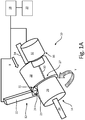
- FIG. 1A is a schematic diagram of a machining system using cryogenic coolant to cool a tool and a heat source to heat a work piece.
- Machining system 10 includes cutting tool 12, work piece 14, heat source 16, controller 18 and user interface 20.
- Cutting tool 12 includes tool holder 22 and tool 24.
- Work piece 14 includes cutting area 25, machined end 26, heating area 27, and un-machined end 26.
- Heat source 16 includes laser 30 and heat source mount 32. Work piece 14 moves along feed 34 indicated by arrow X and is rotated in the direction indicated by arrow Y.
- feed 34 can be a beam, track, or other means of moving work piece 14 as it is being machined at cutting area 25 by tool 12. Simultaneously, work piece 14 is being rotated in direction Y as work piece is moved in direction X on feed 34. As it is moving, portion 27 of work piece 14 is heated by heat source 16. While portion 27 is heated, work piece 14 is rotated in direction Y so that cutting area 25 interacts with tool 12. Tool 12 machines work piece 14 at cutting area 25 downstream of heated portion 27. Controller 18 can direct movement and cutting of tool 12, cooling of tool 12 through cryogenic cooling, application of heat from heat source 16, and movement of feed 34. User interface 20 allows for programming of controller 18.
- Machining system 10 can be used to take work piece 14, a raw material, and cut work piece 14 into a final, desired shape through a controlled material-removal process. This is accomplished by directing tool 12 to cut, shape, drill, press, or otherwise shape work piece 14 at cutting area 25.
- Tool 12 can be, but is not limited to, a drill, turning insert, endmill, tap, or threadmill.
- Tool 12 includes two parts: cutting tool 24 and tool holder 22.
- Cutting tool 24 is secured to tool holder 22, which allows movement of cutting tool 24 as directed by controller 18.
- Controller 18 is a computer numerical control or similar program which can provide instructions to tool 12 on cutting type, depth, direction, and timing. Instructions can be programmed via user interface 20, connected to controller 18.
- Cutting tool 24 is cooled by a cryogenic coolant system.
- Cryogenic coolants are typically liquefied gases, such as liquid nitrogen, hydrogen, or carbon dioxide. Liquid nitrogen is particularly useful for machining purposes as it can be used to chill cutting tool 24 without any environmental run off.
- a coolant, such as liquid nitrogen can be applied to cutting tool 24 through two methods: externally, through a nozzle to cutting tool 24, or internally, through the inside of cutting tool 24.
- the cryogenic coolant is applied through an internal system of channels 31. Channels 31 run through tool 12 and deliver a cryogenic coolant to the inside of cutting tool 24. This cools cutting tool 24 and reduces the wear and tear of tool 12 throughout its lifetime. This can increase tool 12's life span, or increase the cutting speed at which tool 12 can be used without breaking.
- Work piece 14 is heated.
- Work piece 14 includes machined end 26 and un-machined end 26.
- Machined end 26 has already been machined by tool 12, and has been cut or formed to the desired shape.
- Un-machined end 26 has yet to be machined and is raw material.
- Work piece 14 moves along feed 34 in the direction of arrow X, and is heated by heat source 16 as it moves along.
- work piece 14 is worked on by tool 12 as it moves along feed 34.
- work piece 14 is rotated in the direction of arrow 36 to allow tool 12 to work on all surfaces of work piece 14.
- heat source 16 includes laser 30 and heat source mount 32.
- Heat source mount 32 secures laser 30, and controller 18 is connected to heat source mount 32 such that controller 18 can direct the movement and intensity of laser 30.
- Heat source 16 can alternatively include heating coils or other heating devices instead of laser 30.
- Laser 30 is focused to heat the surface of work piece 14 which has not yet been worked on or cut by tool 12. Thus, portion 27 is heated by heat source 16 upstream of tool 12 in the machining process.
- FIG. 1B is a schematic diagram of a machining system using cryogenic coolant to cool a tool and a heat source to heat a work piece in a different embodiment than FIG. 1A . Unless otherwise noted, all parts of FIG. 1B are the same as those in FIG. 1A and are connected in the same fashion.
- cutting tool 24 is cooled by a cryogenic coolant system which is configured differently than the cooling system described in reference to FIG. 1A .
- a cryogenic coolant such as liquid nitrogen
- the cryogenic coolant is applied through external nozzle 33, which sprays cryogenic coolant on an external surface of cutting tool 24. This cools cutting tool 24 and reduces the wear and tear of tool 12 throughout its lifetime. This can increase tool 12's life span, or increase the cutting speed at which tool 12 can be used without breaking.
- FIG. 2 is a flow chart depicting a method of machining a work piece while cooling a cutting tool and heating a work piece simultaneously.
- Process 40 includes securing a cutting tool (step 42), securing a heating source (step 44), mounting a work piece (step 46), loading instructions for the tool and heat source (48), cooling the tool (step 50), heating the work piece (52) and executing the machining instructions (step 54).
- Method 40 begins with securing a cutting tool (step 42), such as cutting tool 24 in FIG. 1 , and a heating source (step 44), such as heating source 16 in FIG. 1 .
- Both cutting tool 24 and heating source 16 should be mounted such that they can be moved and controlled by controller 18.
- cutting tool 24 and heating source 16 will be mounted on separate tool holder 22 and heat source mount 32, respectively, to secure the items above or around feed 34 through which a work piece will travel. (In FIG. 1 , the direction feed 34 moves is indicated by arrow X).
- Feed 34 can be a shaft or rod which can move work piece 14 along as tool 12 machines work piece 14.
- Work piece 14 can be any raw or uncompleted material which will be machined.
- Work piece 14 is angled such that it is properly aligned with cutting tool 24 and heat source 16. Specifically, the area of work piece 14 heated by heat source 16 is located upstream relative cutting tool 24, such that the surface of work piece 14 will be heated before it is worked on by cutting tool 24.
- Heat source 16 is arranged to heat a particular part of work piece 14's surface, portion 27 in FIG. 1 .
- controller 18 can be a simple computer numerical control, or a more complex machine, depending on the machining needs.
- the instructions specify movement and action of cutting tool 24, including timing and depth, in addition to movement and intensity of heating source 16.
- the instructions specify where heat source 16 will be focused and for how long prior to work piece 14 being worked on by tool 12. Instructions programmed in controller 18 can be edited or altered as needed later in method 40.
- cutting tool 24 is cooled with a cryogenic coolant (step 50).
- a cryogenic coolant such as liquid nitrogen, is run through the inside of the cutting tool with internal channels 31, or applied via nozzle 33 to the outside of cutting tool 24, depending on the needs of the machining process. Cooling of tool 12 can be continued and adjusted throughout the reminder of method 40.
- heat source 16 should be turned on and begin to heat portion 27 of work piece 14 (step 52).
- the heating of portion 27 i.e. a portion of work piece 14 upstream of cutting tool 24
- Portion 27 is heated upstream of cutting zone 25, such that cutting zone 25 of work piece 14 is heated before being rotated in direction Y and cut by tool 12.
- the instructions are executed (step 54). Throughout executing of the machining instructions, actions of tool 12, cooling by the cryogenic cooling system (31 or 33), and heating by heat source 16 can be adjusted as needed. Throughout execution of the instructions, work piece 14 will move along feed 34 in the direction of arrow X and be rotated in the direction of arrow Y. Thus, portion 27 will be heated by heat source 16 prior to being machined by tool 12. Un-machined end 26 is the raw material portion of work piece 14, while machined end 26 is the completed, downstream portion of work piece 14 that has already been worked on by cutting tool 24.
- cryogenically cooled tool allows for longer tool life and more aggressive machining techniques with no environmental waste. This occurs because liquid nitrogen, used as a cryogenic coolant, evaporates in to the atmosphere as nitrogen gas and does not leave any other run-off.
- a machining system includes a cutting tool configured to cut a work piece, a cooling scheme configured to cool the cutting tool, and a heat source located upstream relative to the cutting tool.
- the cooling scheme includes a cryogenic coolant and circuitry configured to supply the cryogenic coolant to the cutting tool.
- the heat source is directed at the work piece, wherein the heat source is configured to heat the work piece before the heated work piece is machined by the cutting tool.
- the system of the preceding paragraph can optionally include, additionally and/or alternatively, any one or more of the following features, configurations and/or additional components:
- the cooling system comprises a nozzle configured to deliver the cryogenic coolant to an external surface of the cutting tool.
- the system includes a controller connected to the cutting tool and to the heat source.
- the controlled is configured to provide instructions to control the operation of both the cutting tool and the heat source.
- the system includes a user interface.
- the heat source is a laser.
- the heat source is a heating coil.
- a method for machining includes providing instructions to a machining system, wherein the instructions direct the movement and cutting action of a cutting tool, the movement and heating action of a heat source; cooling the cutting tool with a cryogenic coolant; applying heat to the work piece upstream through the heat source according to the instructions, wherein heating the work piece occur before the work piece reaches the cutting tool; and cutting the work piece according to the instructions.
- the method of the preceding paragraph can optionally include, additionally and/or alternatively, any one or more of the following features, configurations and/or additional components:
- the cryogenic coolant is applied to an internal surface of the cutting tool.
- the heat source is a laser.
- the heat source is a heating coil.
- a machining system includes a cutting tool configured to cut a work piece, means for cooling the cutting tool, and a heat source located upstream relative to the cutting tool.
- the cooling scheme includes a cryogenic coolant and circuitry configured to supply the cryogenic coolant to the cutting tool.
- the heat source is directed at the work piece, wherein the heat source is configured to heat the work piece before the cutting tool cuts the work piece.
- the system of the preceding paragraph can optionally include, additionally and/or alternatively, any one or more of the following features, configurations and/or additional components:
- the means for cooling the cutting tool comprises a nozzle configured to deliver the cryogenic coolant to the cutting tool.
Landscapes
- Engineering & Computer Science (AREA)
- Mechanical Engineering (AREA)
- Physics & Mathematics (AREA)
- Fluid Mechanics (AREA)
- Optics & Photonics (AREA)
- Plasma & Fusion (AREA)
- Turning (AREA)
Abstract
The invention improves machining methods by using cryogenic cooling techniques in combination with a heat source (16) to simultaneously cool a cutting tool (12; 24) while heating a work piece (14) to make the work piece (14) more pliable while increasing efficiency and/or longevity of the cutting tool (12; 24).
Description
- Machining has been used to shape raw materials for decades. Generally, machining techniques take a work piece (a raw material) and cut it into a final, desired shape through a controlled material-removal process. Modem machining processes use a variety of cutting tools to shape work pieces, including drills, turning inserts, endmills, taps, or threadmills. These various tools can be used for machining such as turning, milling and holemaking processes.
- As cutting tools are used in machining processes, they are worn down. Over time, the application of cutting tools to work pieces dulls the tools. This is caused in part by the heat and friction created where the tool meets the work piece. Thus, machining cutting tools are often cooled to increase tool longevity.
- One such method of cooling cutting tools is cryogenic cooling. These methods utilize cryogenic coolants, such as liquid nitrogen or carbon dioxide, to cool the tool. Standard apparatuses for cryogenic cooling are produced by 5ME and Air Products. 5ME's cryogenic machining scheme can be set up with a machining system and runs a coolant through the existing machining system. In contrast, Air Products' IceFly® machining technology is an external scheme that can be applied to the surface of machining systems. Both types of commercially available systems cool a tool used in machining methods.
- A machining system includes a cutting tool configured to cut a work piece, a cooling scheme configured to cool the cutting tool, and a heat source located upstream relative to the cutting tool. The cooling scheme includes a cryogenic coolant and circuitry configured to supply the cryogenic coolant to the cutting tool. The heat source is directed at the work piece, wherein the heat source is configured to heat the work piece before the heated work piece is machined by the cutting tool.
- A method for machining includes providing instructions to a machining system, wherein the instructions direct the movement and cutting action of a cutting tool, the movement and heating action of a heat source; cooling the cutting tool with a cryogenic coolant; applying heat to the work piece upstream through the heat source according to the instructions, wherein heating the work piece occur before the work piece reaches the cutting tool; and cutting the work piece according to the instructions.
- A machining system includes a cutting tool configured to cut a work piece, means for cooling the cutting tool, and a heat source located upstream relative to the cutting tool. The cooling scheme includes a cryogenic coolant and circuitry configured to supply the cryogenic coolant to the cutting tool. The heat source is directed at the work piece, wherein the heat source is configured to heat the work piece before the cutting tool cuts the work piece.
-
-
FIG. 1A is a schematic diagram of one embodiment of a machining system using cryogenic coolant to cool the tool and a heat source to heat the work piece. -
FIG. 1B is a schematic diagram of another embodiment of a machining system using cryogenic coolant to cool the tool and a heat source to heat the work piece. -
FIG. 2 is a flow chart depicting a method for machining a work piece. - The present disclosure presents a machining system including both a cryogenic cooling method for cooling the cutting tool, and a heat source to heat the surface of the work piece. The combination of cooling and heating simultaneously allows for increased tool life and sustainability, and allows for the work piece to be easier to cut. The cutting tool can either be used at the same rate for a longer period of time, or be used more aggressively at a faster rate to finish the machining process faster.
-
FIG. 1A is a schematic diagram of a machining system using cryogenic coolant to cool a tool and a heat source to heat a work piece.Machining system 10 includescutting tool 12,work piece 14,heat source 16,controller 18 anduser interface 20.Cutting tool 12 includestool holder 22 andtool 24.Work piece 14 includescutting area 25, machinedend 26,heating area 27, and un-machinedend 26.Heat source 16 includeslaser 30 andheat source mount 32.Work piece 14 moves alongfeed 34 indicated by arrow X and is rotated in the direction indicated by arrow Y. - In
machining system 10,work piece 14 moves alongfeed 34 in the direction of arrow X and is rotated in the direction of arrow Y.Feed 34 can be a beam, track, or other means of movingwork piece 14 as it is being machined at cuttingarea 25 bytool 12. Simultaneously,work piece 14 is being rotated in direction Y as work piece is moved in direction X onfeed 34. As it is moving,portion 27 ofwork piece 14 is heated byheat source 16. Whileportion 27 is heated,work piece 14 is rotated in direction Y so thatcutting area 25 interacts withtool 12. Tool 12machines work piece 14 at cuttingarea 25 downstream of heatedportion 27.Controller 18 can direct movement and cutting oftool 12, cooling oftool 12 through cryogenic cooling, application of heat fromheat source 16, and movement offeed 34.User interface 20 allows for programming ofcontroller 18. -
Machining system 10 can be used to takework piece 14, a raw material, and cutwork piece 14 into a final, desired shape through a controlled material-removal process. This is accomplished by directingtool 12 to cut, shape, drill, press, or otherwise shapework piece 14 atcutting area 25.Tool 12 can be, but is not limited to, a drill, turning insert, endmill, tap, or threadmill.Tool 12 includes two parts:cutting tool 24 andtool holder 22.Cutting tool 24 is secured totool holder 22, which allows movement ofcutting tool 24 as directed bycontroller 18.Controller 18 is a computer numerical control or similar program which can provide instructions totool 12 on cutting type, depth, direction, and timing. Instructions can be programmed viauser interface 20, connected tocontroller 18. -
Cutting tool 24 is cooled by a cryogenic coolant system. Cryogenic coolants are typically liquefied gases, such as liquid nitrogen, hydrogen, or carbon dioxide. Liquid nitrogen is particularly useful for machining purposes as it can be used to chillcutting tool 24 without any environmental run off. A coolant, such as liquid nitrogen, can be applied to cuttingtool 24 through two methods: externally, through a nozzle to cuttingtool 24, or internally, through the inside ofcutting tool 24. InFIG. 1A , the cryogenic coolant is applied through an internal system ofchannels 31.Channels 31 run throughtool 12 and deliver a cryogenic coolant to the inside ofcutting tool 24. This coolscutting tool 24 and reduces the wear and tear oftool 12 throughout its lifetime. This can increasetool 12's life span, or increase the cutting speed at whichtool 12 can be used without breaking. - At the same time that cutting
tool 24 is cooled with a cryogenic coolant system,work piece 14 is heated.Work piece 14 includes machinedend 26 andun-machined end 26. Machinedend 26 has already been machined bytool 12, and has been cut or formed to the desired shape.Un-machined end 26 has yet to be machined and is raw material.Work piece 14 moves alongfeed 34 in the direction of arrow X, and is heated byheat source 16 as it moves along. Similarly,work piece 14 is worked on bytool 12 as it moves alongfeed 34. Simultaneously,work piece 14 is rotated in the direction of arrow 36 to allowtool 12 to work on all surfaces ofwork piece 14. - While
work piece 14 is moving alongfeed 34,portion 27 ofwork piece 14's surface, betweenmachined end 26 andun-machined end 26, is being heated fromheat source 16.Portion 27 is upstream from cuttingtool 24 and has not yet been machined bytool 12. InFIG. 1 ,heat source 16 includeslaser 30 andheat source mount 32. Heat source mount 32 secureslaser 30, andcontroller 18 is connected to heat source mount 32 such thatcontroller 18 can direct the movement and intensity oflaser 30. Heatsource 16 can alternatively include heating coils or other heating devices instead oflaser 30.Laser 30 is focused to heat the surface ofwork piece 14 which has not yet been worked on or cut bytool 12. Thus,portion 27 is heated byheat source 16 upstream oftool 12 in the machining process. -
FIG. 1B is a schematic diagram of a machining system using cryogenic coolant to cool a tool and a heat source to heat a work piece in a different embodiment thanFIG. 1A . Unless otherwise noted, all parts ofFIG. 1B are the same as those inFIG. 1A and are connected in the same fashion. - In
FIG. 1B , cuttingtool 24 is cooled by a cryogenic coolant system which is configured differently than the cooling system described in reference toFIG. 1A . As discussed earlier, a cryogenic coolant, such as liquid nitrogen, can be applied to cuttingtool 24 through two methods: externally, through a nozzle to cuttingtool 24, or internally, through the inside of cuttingtool 24. InFIG. 1B , the cryogenic coolant is applied throughexternal nozzle 33, which sprays cryogenic coolant on an external surface of cuttingtool 24. This cools cuttingtool 24 and reduces the wear and tear oftool 12 throughout its lifetime. This can increasetool 12's life span, or increase the cutting speed at whichtool 12 can be used without breaking. -
FIG. 2 is a flow chart depicting a method of machining a work piece while cooling a cutting tool and heating a work piece simultaneously.Process 40 includes securing a cutting tool (step 42), securing a heating source (step 44), mounting a work piece (step 46), loading instructions for the tool and heat source (48), cooling the tool (step 50), heating the work piece (52) and executing the machining instructions (step 54). -
Method 40 begins with securing a cutting tool (step 42), such as cuttingtool 24 inFIG. 1 , and a heating source (step 44), such asheating source 16 inFIG. 1 . Both cuttingtool 24 andheating source 16 should be mounted such that they can be moved and controlled bycontroller 18. Typically, cuttingtool 24 andheating source 16 will be mounted onseparate tool holder 22 andheat source mount 32, respectively, to secure the items above or around feed 34 through which a work piece will travel. (InFIG. 1 , the direction feed 34 moves is indicated by arrow X). - Next, a work piece, such as
work piece 14, is mounted on feed 34 (step 46).Feed 34 can be a shaft or rod which can movework piece 14 along astool 12 machines workpiece 14.Work piece 14 can be any raw or uncompleted material which will be machined.Work piece 14 is angled such that it is properly aligned with cuttingtool 24 andheat source 16. Specifically, the area ofwork piece 14 heated byheat source 16 is located upstreamrelative cutting tool 24, such that the surface ofwork piece 14 will be heated before it is worked on by cuttingtool 24. Heatsource 16 is arranged to heat a particular part ofwork piece 14's surface,portion 27 inFIG. 1 . - Once
work piece 14 is mounted, instructions for both cuttingtool 24 andheat source 16 are written or loaded (step 48) intocontroller 18, typically throughuser interface 20.Controller 18 can be a simple computer numerical control, or a more complex machine, depending on the machining needs. The instructions specify movement and action of cuttingtool 24, including timing and depth, in addition to movement and intensity ofheating source 16. The instructions specify whereheat source 16 will be focused and for how long prior towork piece 14 being worked on bytool 12. Instructions programmed incontroller 18 can be edited or altered as needed later inmethod 40. - Before the instructions are executed, cutting
tool 24 is cooled with a cryogenic coolant (step 50). Cuttingtool 24 can be continuously cooled throughout the process to increase tool longevity and prevent dulling of cuttingtool 24. A cryogenic coolant, such as liquid nitrogen, is run through the inside of the cutting tool withinternal channels 31, or applied vianozzle 33 to the outside of cuttingtool 24, depending on the needs of the machining process. Cooling oftool 12 can be continued and adjusted throughout the reminder ofmethod 40. - Additionally,
heat source 16 should be turned on and begin to heatportion 27 of work piece 14 (step 52). The heating of portion 27 (i.e. a portion ofwork piece 14 upstream of cutting tool 24) will occur continuously throughout execution of the instructions bycontroller 18.Portion 27 is heated upstream of cuttingzone 25, such that cuttingzone 25 ofwork piece 14 is heated before being rotated in direction Y and cut bytool 12. - Finally, the instructions are executed (step 54). Throughout executing of the machining instructions, actions of
tool 12, cooling by the cryogenic cooling system (31 or 33), and heating byheat source 16 can be adjusted as needed. Throughout execution of the instructions,work piece 14 will move alongfeed 34 in the direction of arrow X and be rotated in the direction of arrow Y. Thus,portion 27 will be heated byheat source 16 prior to being machined bytool 12.Un-machined end 26 is the raw material portion ofwork piece 14, while machinedend 26 is the completed, downstream portion ofwork piece 14 that has already been worked on by cuttingtool 24. - This process allows for the work piece to be heated prior to being worked on by the cutting tool, allowing pliability of the work piece under the tool. At the same time, the cryogenically cooled tool allows for longer tool life and more aggressive machining techniques with no environmental waste. This occurs because liquid nitrogen, used as a cryogenic coolant, evaporates in to the atmosphere as nitrogen gas and does not leave any other run-off.
- The following are non-exclusive descriptions of possible embodiments of the present invention.
- A machining system includes a cutting tool configured to cut a work piece, a cooling scheme configured to cool the cutting tool, and a heat source located upstream relative to the cutting tool. The cooling scheme includes a cryogenic coolant and circuitry configured to supply the cryogenic coolant to the cutting tool. The heat source is directed at the work piece, wherein the heat source is configured to heat the work piece before the heated work piece is machined by the cutting tool.
- The system of the preceding paragraph can optionally include, additionally and/or alternatively, any one or more of the following features, configurations and/or additional components:
- The cooling system comprises one or more channels inside the cutting tool configured to deliver the cryogenic coolant to an internal surface of the cutting tool.
- The cooling system comprises a nozzle configured to deliver the cryogenic coolant to an external surface of the cutting tool.
- The system includes a controller connected to the cutting tool and to the heat source. The controlled is configured to provide instructions to control the operation of both the cutting tool and the heat source.
- The system includes a user interface.
- The heat source is a laser.
- The heat source is a heating coil.
- A method for machining includes providing instructions to a machining system, wherein the instructions direct the movement and cutting action of a cutting tool, the movement and heating action of a heat source; cooling the cutting tool with a cryogenic coolant; applying heat to the work piece upstream through the heat source according to the instructions, wherein heating the work piece occur before the work piece reaches the cutting tool; and cutting the work piece according to the instructions.
- The method of the preceding paragraph can optionally include, additionally and/or alternatively, any one or more of the following features, configurations and/or additional components:
- The cryogenic coolant is applied to an external surface of the cutting tool.
- The cryogenic coolant is applied to an internal surface of the cutting tool.
- The heat source is a laser.
- The heat source is a heating coil.
- A machining system includes a cutting tool configured to cut a work piece, means for cooling the cutting tool, and a heat source located upstream relative to the cutting tool. The cooling scheme includes a cryogenic coolant and circuitry configured to supply the cryogenic coolant to the cutting tool. The heat source is directed at the work piece, wherein the heat source is configured to heat the work piece before the cutting tool cuts the work piece.
- The system of the preceding paragraph can optionally include, additionally and/or alternatively, any one or more of the following features, configurations and/or additional components:
- The means for cooling the cutting tool comprises one or more channels internal to the cutting tool configured to deliver the cryogenic coolant inside the cutting tool.
- The means for cooling the cutting tool comprises a nozzle configured to deliver the cryogenic coolant to the cutting tool.
- While the invention has been described with reference to an exemplary embodiment(s), it will be understood by those skilled in the art that various changes may be made and equivalents may be substituted for elements thereof without departing from the scope of the invention. In addition, many modifications may be made to adapt a particular situation or material to the teachings of the invention without departing from the essential scope thereof. Therefore, it is intended that the invention not be limited to the particular embodiment(s) disclosed, but that the invention will include all embodiments falling within the scope of the appended claims.
Claims (15)
- A machining system (10) comprising:a cutting tool (12; 24) configured to machine a work piece (14);a cooling system configured to cool the cutting tool (12; 24), wherein the cooling system is configured to deliver a cryogenic coolant to the cutting tool (12; 24); anda heat source (16) directed at the work piece (14), wherein the heat source (16) is positioned with respect to the cutting tool (12; 24) such that the work piece (14) is heated prior to being machined by the cutting tool (12; 24).
- The system of claim 1, wherein the cooling system comprises one or more channels (31) inside the cutting tool (12) configured to deliver the cryogenic coolant to an internal surface of the cutting tool (12).
- The system of claim 1, wherein the cooling system comprises a nozzle (33) configured to deliver the cryogenic coolant to an external surface of the cutting tool (24).
- The system of claim 1, 2 or 3, and further comprising a controller (18) connected to the cutting tool (12; 24) and to the heat source (16), wherein the controller (18) is configured to provide instructions to control the operation of both the cutting tool (12; 24) and the heat source (16).
- The system of claim 4 and further comprising a user interface (20).
- The system of any preceding claim, wherein the heat source (16) is a laser (30).
- The system of any of claims 1 to 5, wherein the heat source (16) comprises a heating coil.
- A method of machining comprising:providing instructions to a machining system (10), wherein the instructions direct the movement and cutting action of a cutting tool (12; 24) and the movement and heating action of a heat source (16);cooling the cutting tool (12; 24) with a cryogenic coolant;applying heat to the work piece (14) using the heat source (16) according to the instructions, wherein a portion of the work piece (14) is heated prior to the portion of the work piece (14) reaching the cutting tool (12; 24); andcutting the work piece (14) according to the instructions.
- The method of claim 8, wherein the cryogenic coolant is applied to an external surface of the cutting tool (24).
- The method of claim 8, wherein the cryogenic coolant is applied to an internal surface of the cutting tool (12).
- The method of claim 8, 9 or 10, wherein the heat source (16) is a laser (30).
- The method of claim 8, 9 or 10, wherein the heat source (16) is a heating coil.
- A machining system (10) comprising:a cutting tool (12; 24) configured to cut a work piece (14);means for cooling the cutting tool (12; 24);a heat source (16) directed at the work piece (14), wherein the heat source (16) is positioned with respect to the cutting tool (12; 24) so that a surface of the work piece (14) is heated upstream of the cutting tool (12; 24), prior to the cutting tool (12; 24) cutting the surface of the work piece (14).
- The system of claim 13, wherein the means for cooling the cutting tool (12) comprises one or more channels (31) internal to the cutting tool (12) configured to deliver cryogenic coolant inside the cutting tool (12).
- The system of claim 13, wherein the means for cooling the cutting tool (24) comprises a nozzle (33) configured to deliver cryogenic coolant to the cutting tool (24).
Applications Claiming Priority (1)
| Application Number | Priority Date | Filing Date | Title |
|---|---|---|---|
| US15/207,473 US20180009058A1 (en) | 2016-07-11 | 2016-07-11 | Machining using cryogenic cooling on a cutting tool while heating a work piece |
Publications (1)
| Publication Number | Publication Date |
|---|---|
| EP3269498A1 true EP3269498A1 (en) | 2018-01-17 |
Family
ID=59296690
Family Applications (1)
| Application Number | Title | Priority Date | Filing Date |
|---|---|---|---|
| EP17178379.8A Withdrawn EP3269498A1 (en) | 2016-07-11 | 2017-06-28 | Machining using cryogenic cooling on a cutting tool while heating a work piece |
Country Status (2)
| Country | Link |
|---|---|
| US (1) | US20180009058A1 (en) |
| EP (1) | EP3269498A1 (en) |
Families Citing this family (1)
| Publication number | Priority date | Publication date | Assignee | Title |
|---|---|---|---|---|
| US10786853B2 (en) | 2018-06-28 | 2020-09-29 | United Technologies Corporation | Cooling system for rotating cutting tools |
Citations (4)
| Publication number | Priority date | Publication date | Assignee | Title |
|---|---|---|---|---|
| EP0842722A1 (en) * | 1996-11-18 | 1998-05-20 | Sandvik Aktiebolag | Cutting insert with internal cooling for chip removing machining |
| US20040104207A1 (en) * | 2002-11-28 | 2004-06-03 | Jinn-Fa Wu | Laser assisted machining method and device |
| EP1580284A2 (en) * | 2004-03-25 | 2005-09-28 | Air Products And Chemicals, Inc. | An apparatus and method for improving work surface during forming and shaping of materials |
| US20110048183A1 (en) * | 2009-02-19 | 2011-03-03 | Purdue Research Foundation | Machining apparatus and process |
-
2016
- 2016-07-11 US US15/207,473 patent/US20180009058A1/en not_active Abandoned
-
2017
- 2017-06-28 EP EP17178379.8A patent/EP3269498A1/en not_active Withdrawn
Patent Citations (4)
| Publication number | Priority date | Publication date | Assignee | Title |
|---|---|---|---|---|
| EP0842722A1 (en) * | 1996-11-18 | 1998-05-20 | Sandvik Aktiebolag | Cutting insert with internal cooling for chip removing machining |
| US20040104207A1 (en) * | 2002-11-28 | 2004-06-03 | Jinn-Fa Wu | Laser assisted machining method and device |
| EP1580284A2 (en) * | 2004-03-25 | 2005-09-28 | Air Products And Chemicals, Inc. | An apparatus and method for improving work surface during forming and shaping of materials |
| US20110048183A1 (en) * | 2009-02-19 | 2011-03-03 | Purdue Research Foundation | Machining apparatus and process |
Also Published As
| Publication number | Publication date |
|---|---|
| US20180009058A1 (en) | 2018-01-11 |
Similar Documents
| Publication | Publication Date | Title |
|---|---|---|
| US11292147B2 (en) | Methods of cutting fiber reinforced polymer composite workpieces with a pure waterjet | |
| US8602845B2 (en) | Strengthening by machining | |
| US20060006157A1 (en) | Method and apparatus for repairing or building up surfaces on a workpiece while the workpiece is mounted on a machine tool | |
| US7441484B1 (en) | CNC prescribe method to encourage chip breaking | |
| ZA200309704B (en) | An apparatus and method for machining with cryogenically cooled oxide-containing ceramic cutting tools. | |
| US9878392B2 (en) | System and method for multiverse controls | |
| CN106078209A (en) | Numerical control multi-head drilling tapping machine | |
| CA2302880C (en) | Method of cutting a workpiece along an arcuate path with a plasma arc torch | |
| US10399173B2 (en) | Laser welding of workpieces by machine | |
| EP3269498A1 (en) | Machining using cryogenic cooling on a cutting tool while heating a work piece | |
| JP2002018674A (en) | Coolant liquid supply device of machining point automatic sighting type | |
| US10610992B2 (en) | Automated interchangeable coolant distributor | |
| CN207386596U (en) | One kind is by gas-cooled NC cutting tool | |
| JP4333468B2 (en) | Grinding machine and coolant supply method | |
| US11458572B2 (en) | Laser smoothing | |
| JP4127247B2 (en) | Grinding equipment | |
| US20180326551A1 (en) | Method Of Sharpening Hardened Thin Metal Blades | |
| KR100667409B1 (en) | Automatic welding machine with preheating function | |
| Kudrna et al. | The technology of the Oxy-fuel cutting on a CNC machine | |
| TW200514644A (en) | Pulsed laser assisted micro precision machining process and device | |
| CN202951960U (en) | Argon tungsten arc welding machine | |
| Choi et al. | NC code generation for laser assisted turn-mill of various type of clovers and square section members | |
| CN104625918A (en) | Numerical control linkage full-automatic straight groove grinding machine | |
| TW202313243A (en) | Method of supplying adaptive composite fluid for mechanical processing capable of achieving better cutting chips removal efficiency and enhancing utilization efficiency of cutting fluid | |
| GB784504A (en) | Improvements in or relating to the machining of metals using liquid carbon dioxide or like medium as a coolant |
Legal Events
| Date | Code | Title | Description |
|---|---|---|---|
| PUAI | Public reference made under article 153(3) epc to a published international application that has entered the european phase |
Free format text: ORIGINAL CODE: 0009012 |
|
| STAA | Information on the status of an ep patent application or granted ep patent |
Free format text: STATUS: THE APPLICATION HAS BEEN PUBLISHED |
|
| AK | Designated contracting states |
Kind code of ref document: A1 Designated state(s): AL AT BE BG CH CY CZ DE DK EE ES FI FR GB GR HR HU IE IS IT LI LT LU LV MC MK MT NL NO PL PT RO RS SE SI SK SM TR |
|
| AX | Request for extension of the european patent |
Extension state: BA ME |
|
| STAA | Information on the status of an ep patent application or granted ep patent |
Free format text: STATUS: THE APPLICATION IS DEEMED TO BE WITHDRAWN |
|
| 18D | Application deemed to be withdrawn |
Effective date: 20180718 |