EP3269488A1 - Joining head, joining element holder, joining robot and method of joining - Google Patents
Joining head, joining element holder, joining robot and method of joining Download PDFInfo
- Publication number
- EP3269488A1 EP3269488A1 EP17179743.4A EP17179743A EP3269488A1 EP 3269488 A1 EP3269488 A1 EP 3269488A1 EP 17179743 A EP17179743 A EP 17179743A EP 3269488 A1 EP3269488 A1 EP 3269488A1
- Authority
- EP
- European Patent Office
- Prior art keywords
- joining
- joining element
- head
- clamping
- joined
- Prior art date
- Legal status (The legal status is an assumption and is not a legal conclusion. Google has not performed a legal analysis and makes no representation as to the accuracy of the status listed.)
- Granted
Links
Images

Classifications
-
- B—PERFORMING OPERATIONS; TRANSPORTING
- B23—MACHINE TOOLS; METAL-WORKING NOT OTHERWISE PROVIDED FOR
- B23K—SOLDERING OR UNSOLDERING; WELDING; CLADDING OR PLATING BY SOLDERING OR WELDING; CUTTING BY APPLYING HEAT LOCALLY, e.g. FLAME CUTTING; WORKING BY LASER BEAM
- B23K9/00—Arc welding or cutting
- B23K9/20—Stud welding
- B23K9/201—Stud welding of the extremity of a small piece on a large basis
-
- B—PERFORMING OPERATIONS; TRANSPORTING
- B23—MACHINE TOOLS; METAL-WORKING NOT OTHERWISE PROVIDED FOR
- B23K—SOLDERING OR UNSOLDERING; WELDING; CLADDING OR PLATING BY SOLDERING OR WELDING; CUTTING BY APPLYING HEAT LOCALLY, e.g. FLAME CUTTING; WORKING BY LASER BEAM
- B23K11/00—Resistance welding; Severing by resistance heating
- B23K11/002—Resistance welding; Severing by resistance heating specially adapted for particular articles or work
- B23K11/004—Welding of a small piece to a large or broad piece
- B23K11/0046—Welding of a small piece to a large or broad piece the extremity of a small piece being welded to a base, e.g. cooling studs or fins to tubes or plates
- B23K11/0053—Stud welding, i.e. resistive
-
- B—PERFORMING OPERATIONS; TRANSPORTING
- B23—MACHINE TOOLS; METAL-WORKING NOT OTHERWISE PROVIDED FOR
- B23K—SOLDERING OR UNSOLDERING; WELDING; CLADDING OR PLATING BY SOLDERING OR WELDING; CUTTING BY APPLYING HEAT LOCALLY, e.g. FLAME CUTTING; WORKING BY LASER BEAM
- B23K9/00—Arc welding or cutting
- B23K9/20—Stud welding
- B23K9/206—Stud welding with automatic stud supply
Definitions
- the present invention relates to a joining head for joining, preferably welding, joining elements, having a joining element holder, which has a clamping portion for clamping a joining element to be joined, wherein the clamping portion is designed to exert a radially inward-directed clamping force for clamping the joining element to be joined, wherein the joining element holder has an introduction portion at an axial end opposite the clamping portion, wherein joining elements can be fed to the joining element holder via the introduction portion; a loading pin for absorbing axial forces which occur during a joining process, wherein the joining element to be joined can be pushed axially into a joining position by the loading pin before a joining process, with the result that the joining element to be joined is clamped in the clamping portion and projects axially from the joining element holder in a joining direction; and a fluid cylinder for actuating the loading pin.
- a joining head of this kind is already known in the prior art, wherein the joining element holder of the joining head can be of slotted or collet-type construction, for example, and, in particular, can have a contour matched to the joining element on the clamping portion, and wherein the clamping portion can be designed in such a way that, when a joining element is moved into a joining position, the clamping portion expands radially outwards to allow the joining element to be joined to be pushed through at least partially.
- the joining elements are preferably blown into a storage position (this process of blowing in is in some cases also referred to as shooting) and are then pushed axially in a joining direction into a joining position by means of the loading pin.
- the loading pin preferably remains in the forward position, thus enabling axial forces that occur during a joining process to be absorbed by the loading pin.
- the present invention furthermore relates to a joining element holder, to a joining robot and to a method for joining joining elements.
- Joining joining elements e.g. weld studs, balls, weld nuts, T-bolts, annular flanged studs etc.
- Joining joining elements e.g. weld studs, balls, weld nuts, T-bolts, annular flanged studs etc.
- This includes, in particular, "stud welding", in which a joining element is welded to the surface of a workpiece.
- Alternative joining techniques comprise adhesive bonding of a joining element to the surface of a workpiece, for example.
- Processes of this kind are often carried out in an automated way, especially in the motor vehicle industry, wherein a large number of joining elements is joined to a vehicle panel, in particular the body panel, in order to act as anchors for fastening devices, trim elements etc. or as earthing studs, for example.
- automated joining of joining elements to workpieces is achieved by means of a joining head on a robot arm.
- the joining head is connected to a supply device, which supplies the electric joining current (welding current and/or induction current) and other control signals, for example.
- the joining elements are fed to the joining head in an automated manner. Generally, this is accomplished by means of compressed air through "supply hoses".
- the clamping portion and the loading pin serve to hold the stud in a defined standby position/joining position, starting from which a joining process can be initiated.
- the joining head has a guiding portion, wherein the guiding portion is designed to accommodate at least one joining element, preferably two, three, four, five... joining elements, e.g. studs, weld balls, flanged studs etc., such that axial forces between the joining element to be joined in the joining position and the loading pin can be transmitted via the at least one joining element accommodated in the guiding portion.
- the joining head has a guiding portion, wherein the guiding portion is designed to accommodate at least one joining element, preferably two, three, four, five... joining elements, e.g. studs, weld balls, flanged studs etc.
- a plurality of joining elements preferably two to five, in particular two to ten or more joining elements, can be accommodated in the guiding portion.
- the guiding portion can have a large axial length without the need to increase the loading pin travel and the fluid cylinder travel in a corresponding manner. Consequently, it is possible to provide a joining head with a long guiding portion without correspondingly increasing the size of interfering contours arising at a joining-head end opposite the joining end.
- the joining elements situated in the guiding portion act as a kind of column/stack and transmit the axial forces occurring during the joining process between the joining element to be joined and the loading pin, and it is possible, in particular, in this way for a supporting force of the loading pin to be transmitted as far as the joining element to be joined.
- joining elements can be fed to the joining element holder or guiding portion before a joining process as follows: first of all, a joining element is blown in front of or into the introduction portion by means of compressed air via a supply hose or the like, and then this joining element is moved axially in the joining direction by means of the loading pin, after which the loading pin is moved back in the axially opposite direction and, finally, a further joining element is blown in front of or into the introduction portion, thus allowing the loading pin to move this further joining element axially in the joining direction.
- This process is preferably repeated until the joining element holder or guiding portion has been filled with joining elements, thus allowing axial forces to be transmitted between a joining element to be joined and the loading pin via the joining elements situated in the joining element holder or guiding portion.
- a distance piece/distance stud which is accommodated together with the joining elements in the joining element holder or guiding portion in order in this way to enable different joining element types, in particular joining element types of different axial length, to be joined using the same joining head.
- the distance stud is moved along in the same way as a joining element. If there is no joining element to be joined ahead of the distance stud in the joining direction, i.e. when the distance stud is as it were in the joining position, the distance stud is removed, preferably ejected, and a new distance stud or the same distance stud is fed in again to enable the missing axial length/the missing axial travel of the loading pin to be compensated.
- a joining element holder for a joining head in particular for a joining head described above, having a clamping portion for clamping a joining element to be joined, wherein the clamping portion is designed to exert a radially inward-directed clamping force for clamping the joining element to be joined, and having an introduction portion at an axial end opposite the clamping portion, wherein joining elements can be fed to the joining element holder via the introduction portion, wherein the joining element holder has a guiding portion between the clamping portion and the introduction portion, wherein the guiding portion is designed to accommodate at least one joining element, such that axial forces between a joining element held in the clamping portion and a loading pin can be transmitted by at least one joining element accommodated in the guiding portion.
- a joining element holder of this kind can preferably also be used to retrofit already existing systems.
- a joining element holder prefilled with joining elements manually i.e. by hand
- the above object is furthermore achieved by an automated robot for joining joining elements having a joining head according to Claim 1.
- the joining robot preferably has a multi-axis robot arm, wherein the feeds for the joining elements, control signals and welding current are preferably integrated into the robot arm or can be mounted on the robot arm.
- the feeds can also be provided at some other location.
- the above object is furthermore achieved by means of a method for joining joining elements, preferably for joining by means of a joining head described above.
- the method has the following steps: feeding a joining element through an introduction portion of a joining element holder, wherein the joining element is preferably blown in front of the introduction portion and then pushed by means of a loading pin through a retention device for captive retention; feeding at least one further joining element into a guiding portion, such that the further joining element can transmit axial forces between a loading pin and the first joining element fed in; axial movement of the first joining element fed in into a joining position by means of the loading pin and of the at least one further joining element, wherein, in the joining position, the joining element to be joined is clamped in a clamping portion of the joining element holder and projects axially from the joining element holder in a joining direction; supporting the joining element which is in the joining position by means of the loading pin and of the at least one further joining element; axial movement of a joining head in the joining direction; and joining the joining element
- the guiding portion is arranged between the clamping portion and the introduction portion. This enables the joining head to be produced in a structurally simple manner.
- the guiding portion has a guiding sleeve, which is arranged at least partially radially within the joining element holder and which is preferably made of plastic and designed to be interchangeable. It is thereby possible to adapt the guiding sleeve specifically to the joining elements to be joined. Moreover, only small forces preferably act on the guiding sleeve, thus allowing the guiding sleeve to be produced from a lower-cost material. In the event of damage or wear to the guiding sleeve, this can preferably be exchanged easily and quickly without having to exchange the complete joining element holder or joining head.
- the guiding sleeve preferably electrically insulates the joining element holder and/or the joining head from the at least one joining element accommodated in the guiding portion.
- a welding current can be fed to the joining element to be joined in a structurally simple manner, e.g. via the joining element holder, without the occurrence of sparkovers within the joining element holder or joining head.
- the joining head is less prone to faults.
- the joining head has a retention device in order to hold a joining element captive in the guiding portion.
- the retention device can have a catch that can be actuated by an actuator for example or, in the case of ferromagnetic joining elements, can have a magnet.
- the joining elements already pushed into the guiding portion cannot get back into the feed channel in the event of a drop-off in the compressed air.
- the joining head is less prone to faults.
- the retention device is designed as a radial constriction in the introduction portion. It is thereby possible to implement the retention device in a low-cost and structurally simple manner involving a small installation space requirement.
- the radial constriction preferably expands outwards in a radial direction.
- the introduction portion is connected to a radially extending feed channel. This preferred embodiment enables the interfering contours on the joining head to be further reduced.
- the present invention relates to a joining head having a joining element holder, preferably having a guiding sleeve, and to a loading pin for a stud welding device, wherein the guiding sleeve can preferably be clipped in and can be of electrically insulated or uninsulated design.
- the guiding sleeve preferably serves for centred guidance of the joining elements/studs.
- the joining element holder and the guiding sleeve are preferably of slotted design.
- the guiding sleeve is preferably provided with a conically tapering constriction from the introduction/infeed side, wherein this constriction prevents the joining elements from flying through when injected or from getting back into the feed channel if there is a drop-off in the feed air.
- the loading pin can push the joining elements successively through the conical constriction of the guiding sleeve until the guiding sleeve has been completely filled with joining elements.
- the column/stack of joining elements acts like a multi-part loading pin.
- the length of the joining element holder and of the guiding sleeve preferably depends on the corresponding joining element length.
- attachment of a corresponding joining element holder allows the same loading pin to be used in a joining head.
- joining elements are held by means of a joining element holder which is slotted two to x times.
- a joining element is shot-in, loaded with a loading pin and joined, preferably welded, for each welding cycle.
- the disadvantage here is the large loading pin travel, which means that the joining head has a large interfering contour and hence poor accessibility.
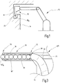
- Fig. 1 shows a joining head 10, which is arranged on an arm of a joining robot 12 in order to process a workpiece 14.
- a joining element 16 is to be joined to the workpiece 14.
- the joining head 10 has a joining element holder 18.
- the joining element 16 K in this example a stud, is clamped in a clamping portion 20 of the joining element holder 18.
- the workpiece 14 has a special contour, by means of which the advantages of the present invention can be clearly shown.
- the axially long joining element holder 18 makes it possible to fit the joining element 16 K in a recess in the workpiece 14, wherein the joining head 10 according to the invention does not have an interfering contour at an end opposite the joining end, that is to say, in particular, is of axially short construction. This enables the joining head 10 to fit a joining element 16 in a recess even though the workpiece 14 has an interfering profile on a side opposite the joining location in the joining direction. Owing to the interfering profile of the workpiece 14, the joining head 10 may have only a limited maximum axial length.
- joining elements 16 often have to be attached as anchors for trim components or as earthing studs and these anchors/earthing studs are preferably to be joined at locations which are accessible only with difficulty.
- Fig. 2a shows schematically a joining head 10 I for joining weld balls 16 I .
- a total of six weld balls 16 I is accommodated in the joining element holder 18.
- the number of joining elements 16 I accommodated in the joining element holder 18 is chosen only by way of example here and, of course, it is also possible for more or fewer joining elements 16 I to be accommodated, depending on the specification required. It is self-evident that the joining element holder 18 can be made axially longer or shorter in a corresponding way.
- the joining head 10 I is shown in the joining position, wherein the joining element 16 I K clamped into the clamping portion 20 is supported by virtue of the fact that a loading pin 24 rests against the last joining element 16 I fed in in the region of an introduction portion 22.
- the joining elements 16 I stored in a guiding portion 26 of the joining element holder 18 can transmit axial forces, which occur especially during the joining process itself, between the joining element 16 I K to be joined and the loading pin 24.
- the loading pin 24 is moved axially forwards or backwards along a joining axis by a schematically illustrated fluid cylinder 28, wherein the fluid cylinder 28 has a piston 30, the cross-sectional area of which is preferably chosen to match the force to be applied axially.
- the loading pin 24 is in operative connection with the fluid cylinder piston 30 and is preferably accommodated in a guide 32.
- Fig. 2a schematically illustrates a feed channel 34 for further joining elements 16 I , said channel being connected to the introduction portion 22.
- further joining elements 16 I can be blown into a storage position, preferably individually, i.e. in front of or into the introduction portion 22, and can then be pushed axially into the guiding portion 26 in the joining direction by means of the loading pin 24.
- joining element 16 I In order to join a joining element 16 I , it is preferred to fill the joining element holder 18 with joining elements 16 I , thus allowing these joining elements 16 I to transmit axial forces between the loading pin 24 and the joining element 16 I K to be joined.
- the loading pin 24 is pulled back axially counter to the joining direction in order to free the introduction portion 22, if this has not already taken place. After that, a joining element 16 I is blown into or in front of the introduction portion 22.
- the loading pin 24 is moved in the joining direction and pushes the last joining element 16 I fed in into the guiding portion 26 of the joining element holder 18. After that, the loading pin 24 is pulled back again and frees the introduction portion 22. Thus, a further joining element 16 I can be blown into or in front of the introduction portion 22. This process is repeated until the guiding portion 26 of the joining element holder 18 has been filled.
- the joining element holder 18, the joining head 10 or the joining robot 12 preferably have a detection device, which can detect whether the guiding portion 26 of the joining element holder 18 has been filled. This can be accomplished, for example, by counting the joining elements 16 fed in or by measuring a force required to press the last joining element 16 fed in into the guiding portion 26 of the joining element holder 18 by means of the loading pin 24. If the guiding portion 26 of the joining element holder 18 has been completely filled, then, when the last joining element 16 fed in is pushed through, the joining element 16 which is furthest in the joining direction is pushed into the clamping portion 20, i.e. into the joining position, this resulting in a high expenditure of force since the clamping portion 20 first of all has to be pushed open radially outwards. The joining element 16 K can then be joined in a manner known per se from the prior art.
- the joining elements 16 are fed to the joining head 10 by being blown in using compressed air, which is to be taken as illustrated.
- the joining elements 16 can also be accommodated from the outset or can be fed to the joining element holder 18 by methods known per se in the prior art without exceeding the scope of the present invention.
- the joined joining element 16 I remains on the workpiece, wherein initially no further joining element 16 I follows on into the joining position.
- the clamping portion 20 initially remains substantially free.
- the loading pin 24 is moved back by means of the fluid cylinder 28, thus allowing a further joining element 16 I to be blown in front of or into the introduction portion 22.
- the loading pin 24 is then moved axially in the joining direction and pushes the last joining element 16 I to be fed in axially in the joining direction, with the result that all the joining elements 16 I situated in the guiding portion 26 are moved axially in the joining direction.
- the joining element 16 I K which is furthest in the joining direction is pushed into the joining position and clamped in the clamping portion 20.
- the loading pin 24 preferably remains in this position, thus allowing the joining element 16 I K situated in the joining position, i.e. clamped in the clamping portion 20, to be joined.
- the joining element holder 18 is preferably of slotted design in the axial direction, with the result that, when a joining element 16 I is pushed into the joining position, the axially extending tongues formed by the slots bend open radially outwards and then clamp the joining element 16 I K to be joined in the clamping portion 20.
- Fig. 2b shows another joining head 10", the structure of which corresponds substantially to the joining head 10" shown in Fig. 2a .
- weld studs 16 not weld balls 16 I , are shown.
- the joining head 10" is in the joining position.
- the loading pin 24 has been extended axially in the joining direction and is resting on the last joining element 16" fed in, with the result that axial forces can be exchanged or transmitted between the joining element 16 II K to be joined and the loading pin 24 by the joining elements 16" situated in the guiding portion 26 of the joining element holder 18.
- the last joining element 16" to be fed in through the feed channel 34 is preferably pushed into the guiding portion 26 of the joining element holder 18 by the loading pin 24, wherein the loading pin 24 then remains in this axial position, at least until the joining element 16 II K to be joined has been joined.
- Fig. 2c shows a further embodiment, which corresponds substantially to the structure of the embodiments shown in Figs 2a and 2b .
- the joining head 10 III in Fig. 2c is likewise in a joining configuration.
- Flanged studs 16 III are accommodated in the joining element holder 18 of the joining head 10 III .
- FIG. 3 Another embodiment of a joining head 10 IV is shown in Fig. 3 .
- the joining head 10 IV corresponds substantially to the joining heads 10 in the embodiments which are shown in Figs 2a-2c , and identical features are therefore denoted by the same reference numerals.
- the loading pin 24 is shown in a retracted position, in which it is preferably accommodated completely in the guide 32.
- the joining element holder 18 has a guiding sleeve 36, in which the joining elements 16 I , in this example weld balls, are accommodated.
- the guiding portion 26 of the joining element holder 18 is completely filled with joining elements 16 I .
- the guiding sleeve 36 has a radial constriction 38 on the introduction portion 22.
- This radial constriction 38 acts as a retention device, which prevents joining elements 16 I in the guiding portion 26 getting back into the feed channel 34.
- the guiding sleeve 36 is preferably of slotted design in the axial direction, as is the joining element holder 18, namely in such a way that the guiding sleeve 36 can expand radially outwards in the feed region 22 when a joining element 16 I is pushed axially in the joining direction by the loading pin 24 and is pushed through the radial construction 38.
- the guiding sleeve 36 is preferably manufactured from plastic and is interchangeable. This enables a joining element holder 18 or a joining head 10 to be converted to different types of joining elements 16 by inserting different guiding sleeves 36.
- the guiding sleeve 36 can preferably be clipped into the joining element holder 18 or the joining head 10. Of course, bonding in, screwing in or pushing in the guiding sleeve 36 is also possible.
- the guiding sleeve 36 preferably electrically insulates all the joining elements 16, apart from the joining element 16 K to be joined, from the joining element holder 18 and/or the joining head 10.
Landscapes
- Engineering & Computer Science (AREA)
- Mechanical Engineering (AREA)
- Physics & Mathematics (AREA)
- Plasma & Fusion (AREA)
- Automatic Assembly (AREA)
Abstract
Description
- The present invention relates to a joining head for joining, preferably welding, joining elements, having a joining element holder, which has a clamping portion for clamping a joining element to be joined, wherein the clamping portion is designed to exert a radially inward-directed clamping force for clamping the joining element to be joined, wherein the joining element holder has an introduction portion at an axial end opposite the clamping portion, wherein joining elements can be fed to the joining element holder via the introduction portion; a loading pin for absorbing axial forces which occur during a joining process, wherein the joining element to be joined can be pushed axially into a joining position by the loading pin before a joining process, with the result that the joining element to be joined is clamped in the clamping portion and projects axially from the joining element holder in a joining direction; and a fluid cylinder for actuating the loading pin.
- A joining head of this kind is already known in the prior art, wherein the joining element holder of the joining head can be of slotted or collet-type construction, for example, and, in particular, can have a contour matched to the joining element on the clamping portion, and wherein the clamping portion can be designed in such a way that, when a joining element is moved into a joining position, the clamping portion expands radially outwards to allow the joining element to be joined to be pushed through at least partially.
- In joining heads of this kind, the joining elements are preferably blown into a storage position (this process of blowing in is in some cases also referred to as shooting) and are then pushed axially in a joining direction into a joining position by means of the loading pin.
- The loading pin preferably remains in the forward position, thus enabling axial forces that occur during a joining process to be absorbed by the loading pin.
- The present invention furthermore relates to a joining element holder, to a joining robot and to a method for joining joining elements.
- Joining joining elements, e.g. weld studs, balls, weld nuts, T-bolts, annular flanged studs etc., to the surface of a workpiece is a known practice in the field of joining technology. This includes, in particular, "stud welding", in which a joining element is welded to the surface of a workpiece. Alternative joining techniques comprise adhesive bonding of a joining element to the surface of a workpiece, for example.
- Processes of this kind are often carried out in an automated way, especially in the motor vehicle industry, wherein a large number of joining elements is joined to a vehicle panel, in particular the body panel, in order to act as anchors for fastening devices, trim elements etc. or as earthing studs, for example. Generally, automated joining of joining elements to workpieces is achieved by means of a joining head on a robot arm. In this case, the joining head is connected to a supply device, which supplies the electric joining current (welding current and/or induction current) and other control signals, for example.
- It is furthermore preferred if the joining elements are fed to the joining head in an automated manner. Generally, this is accomplished by means of compressed air through "supply hoses". The clamping portion and the loading pin serve to hold the stud in a defined standby position/joining position, starting from which a joining process can be initiated.
- In automated vehicle production, it is necessary, for example, to join a plurality of joining elements to a workpiece, preferably the body. In this case, locations at which a joining element is to be joined may in some cases be accessible only with difficulty.
- The provision of an axially long joining element holder can therefore be envisaged. This makes it possible to carry out joining even at locations which can be reached only with difficulty since the joining element holder preferably has a smaller radial extent than the joining head.
- In the case of joining heads having joining element holders of this kind, a loading pin with a corresponding loading pin travel and, accordingly, a fluid cylinder with a corresponding fluid cylinder travel must be provided. As a consequence, large interfering contours arise on that axial end of a joining head which lies opposite a joining tip/a joining end, especially owing to the fluid cylinder. These interfering contours can limit the accessibility of the joining head.
- It is therefore the underlying object of the present invention to indicate an improved joining head, an improved joining element holder, an improved joining robot and an improved joining method, in particular for joining in locations that are difficult to access.
- This object is achieved, in the case of the joining head mentioned at the outset, in that the joining head has a guiding portion, wherein the guiding portion is designed to accommodate at least one joining element, preferably two, three, four, five... joining elements, e.g. studs, weld balls, flanged studs etc., such that axial forces between the joining element to be joined in the joining position and the loading pin can be transmitted via the at least one joining element accommodated in the guiding portion.
- By means of the at least one joining element in the guiding portion, axial forces which occur during the joining process can be transmitted from the element to be joined to the loading pin via the at least one joining element in the guiding portion. It is thereby possible to shorten the required travel of the loading pin and hence also that of the fluid cylinder actuating the loading pin in accordance with the length of the at least one joining element situated in the joining element holder.
- A plurality of joining elements, preferably two to five, in particular two to ten or more joining elements, can be accommodated in the guiding portion. As a result, the guiding portion can have a large axial length without the need to increase the loading pin travel and the fluid cylinder travel in a corresponding manner. Consequently, it is possible to provide a joining head with a long guiding portion without correspondingly increasing the size of interfering contours arising at a joining-head end opposite the joining end.
- Here, the joining elements situated in the guiding portion act as a kind of column/stack and transmit the axial forces occurring during the joining process between the joining element to be joined and the loading pin, and it is possible, in particular, in this way for a supporting force of the loading pin to be transmitted as far as the joining element to be joined.
- In this case, joining elements can be fed to the joining element holder or guiding portion before a joining process as follows: first of all, a joining element is blown in front of or into the introduction portion by means of compressed air via a supply hose or the like, and then this joining element is moved axially in the joining direction by means of the loading pin, after which the loading pin is moved back in the axially opposite direction and, finally, a further joining element is blown in front of or into the introduction portion, thus allowing the loading pin to move this further joining element axially in the joining direction.
- This process is preferably repeated until the joining element holder or guiding portion has been filled with joining elements, thus allowing axial forces to be transmitted between a joining element to be joined and the loading pin via the joining elements situated in the joining element holder or guiding portion.
- It is also conceivable to accommodate different joining element types in a joining element holder or guiding portion of this kind in order to be able to join different joining element types using the same joining head. It is self-evident that an appropriate way of feeding in the joining elements is preferably used for this purpose.
- It is furthermore conceivable to provide a distance piece/distance stud, which is accommodated together with the joining elements in the joining element holder or guiding portion in order in this way to enable different joining element types, in particular joining element types of different axial length, to be joined using the same joining head. In this case, the distance stud is moved along in the same way as a joining element. If there is no joining element to be joined ahead of the distance stud in the joining direction, i.e. when the distance stud is as it were in the joining position, the distance stud is removed, preferably ejected, and a new distance stud or the same distance stud is fed in again to enable the missing axial length/the missing axial travel of the loading pin to be compensated.
- The object is furthermore achieved by a joining element holder for a joining head, in particular for a joining head described above, having a clamping portion for clamping a joining element to be joined, wherein the clamping portion is designed to exert a radially inward-directed clamping force for clamping the joining element to be joined, and having an introduction portion at an axial end opposite the clamping portion, wherein joining elements can be fed to the joining element holder via the introduction portion, wherein the joining element holder has a guiding portion between the clamping portion and the introduction portion, wherein the guiding portion is designed to accommodate at least one joining element, such that axial forces between a joining element held in the clamping portion and a loading pin can be transmitted by at least one joining element accommodated in the guiding portion.
- A joining element holder of this kind can preferably also be used to retrofit already existing systems. In the case of a joining element holder prefilled with joining elements manually, i.e. by hand, it is preferable if no reprogramming of the joining program sequence is necessary here. In general, however, it is of course also possible to adapt the joining program sequence accordingly during conversion.
- The above object is furthermore achieved by an automated robot for joining joining elements having a joining head according to Claim 1.
- The joining robot preferably has a multi-axis robot arm, wherein the feeds for the joining elements, control signals and welding current are preferably integrated into the robot arm or can be mounted on the robot arm. The feeds can also be provided at some other location.
- The above object is furthermore achieved by means of a method for joining joining elements, preferably for joining by means of a joining head described above. The method has the following steps: feeding a joining element through an introduction portion of a joining element holder, wherein the joining element is preferably blown in front of the introduction portion and then pushed by means of a loading pin through a retention device for captive retention; feeding at least one further joining element into a guiding portion, such that the further joining element can transmit axial forces between a loading pin and the first joining element fed in; axial movement of the first joining element fed in into a joining position by means of the loading pin and of the at least one further joining element, wherein, in the joining position, the joining element to be joined is clamped in a clamping portion of the joining element holder and projects axially from the joining element holder in a joining direction; supporting the joining element which is in the joining position by means of the loading pin and of the at least one further joining element; axial movement of a joining head in the joining direction; and joining the joining element that is in the joining position to a workpiece.
- The object is thus fully achieved.
- In a preferred embodiment, the guiding portion is arranged between the clamping portion and the introduction portion. This enables the joining head to be produced in a structurally simple manner.
- In another preferred embodiment, the guiding portion has a guiding sleeve, which is arranged at least partially radially within the joining element holder and which is preferably made of plastic and designed to be interchangeable. It is thereby possible to adapt the guiding sleeve specifically to the joining elements to be joined. Moreover, only small forces preferably act on the guiding sleeve, thus allowing the guiding sleeve to be produced from a lower-cost material. In the event of damage or wear to the guiding sleeve, this can preferably be exchanged easily and quickly without having to exchange the complete joining element holder or joining head.
- It is furthermore possible to convert the same joining element holder or joining head to different joining element types by providing different guiding sleeves. It is thereby possible to convert a joining robot already fitted with a joining head of this kind in a short time and with little effort.
- The guiding sleeve preferably electrically insulates the joining element holder and/or the joining head from the at least one joining element accommodated in the guiding portion. In this way, a welding current can be fed to the joining element to be joined in a structurally simple manner, e.g. via the joining element holder, without the occurrence of sparkovers within the joining element holder or joining head. As a result, the joining head is less prone to faults.
- Provision can preferably also be made for the loading pin to be electrically insulated, at least at the end which touches the joining elements. It is furthermore also possible for a loading pin guide to be of insulated construction. In this way, sparkovers can be further reduced.
- In a preferred embodiment, the joining head has a retention device in order to hold a joining element captive in the guiding portion.
- The retention device can have a catch that can be actuated by an actuator for example or, in the case of ferromagnetic joining elements, can have a magnet.
- By virtue of the retention device, the joining elements already pushed into the guiding portion cannot get back into the feed channel in the event of a drop-off in the compressed air. As a result, the joining head is less prone to faults. Moreover, it is possible, during filling, to prevent the joining elements from shooting through and hence to prevent damage to the guiding sleeve or to the joining elements already in the guiding portion.
- In a particularly preferred embodiment, the retention device is designed as a radial constriction in the introduction portion. It is thereby possible to implement the retention device in a low-cost and structurally simple manner involving a small installation space requirement.
- As the joining elements are pushed through the retention device, the radial constriction preferably expands outwards in a radial direction.
- In a preferred embodiment, the introduction portion is connected to a radially extending feed channel. This preferred embodiment enables the interfering contours on the joining head to be further reduced.
- Overall, the present invention relates to a joining head having a joining element holder, preferably having a guiding sleeve, and to a loading pin for a stud welding device, wherein the guiding sleeve can preferably be clipped in and can be of electrically insulated or uninsulated design. The guiding sleeve preferably serves for centred guidance of the joining elements/studs.
- The joining element holder and the guiding sleeve are preferably of slotted design. The guiding sleeve is preferably provided with a conically tapering constriction from the introduction/infeed side, wherein this constriction prevents the joining elements from flying through when injected or from getting back into the feed channel if there is a drop-off in the feed air. The loading pin can push the joining elements successively through the conical constriction of the guiding sleeve until the guiding sleeve has been completely filled with joining elements. The column/stack of joining elements acts like a multi-part loading pin.
- Here, the length of the joining element holder and of the guiding sleeve preferably depends on the corresponding joining element length. Depending on the type of joining element, attachment of a corresponding joining element holder allows the same loading pin to be used in a joining head.
- According to the prior art, joining elements are held by means of a joining element holder which is slotted two to x times. In this case, a joining element is shot-in, loaded with a loading pin and joined, preferably welded, for each welding cycle. The disadvantage here is the large loading pin travel, which means that the joining head has a large interfering contour and hence poor accessibility.
- It is self-evident that the features which are mentioned above and those which remain to be explained below can be used not only in the respectively indicated combination but also in other combinations or in isolation without exceeding the scope of the present invention.
- Illustrative embodiments of the invention are shown in the drawings and are explained in greater detail in the following description. In the drawings:
- Fig. 1
- shows a schematic illustration of a joining robot according to the invention,
- Figs. 2a-c
- show schematically a partial cross section through a joining head according to the invention, having a joining element holder, a loading pin and a fluid cylinder, each with different types of joining element, and
- Fig. 3
- shows a joining element holder according to the invention having a guiding sleeve.
-
Fig. 1 shows a joininghead 10, which is arranged on an arm of a joiningrobot 12 in order to process aworkpiece 14. In this case, a joiningelement 16 is to be joined to theworkpiece 14. The joininghead 10 has a joiningelement holder 18. The joiningelement 16K, in this example a stud, is clamped in a clampingportion 20 of the joiningelement holder 18. - The
workpiece 14 has a special contour, by means of which the advantages of the present invention can be clearly shown. The axially long joiningelement holder 18 makes it possible to fit the joiningelement 16K in a recess in theworkpiece 14, wherein the joininghead 10 according to the invention does not have an interfering contour at an end opposite the joining end, that is to say, in particular, is of axially short construction. This enables the joininghead 10 to fit a joiningelement 16 in a recess even though theworkpiece 14 has an interfering profile on a side opposite the joining location in the joining direction. Owing to the interfering profile of theworkpiece 14, the joininghead 10 may have only a limited maximum axial length. - Such joining requirements can arise especially in motor vehicle construction/body construction since, in this case, joining
elements 16 often have to be attached as anchors for trim components or as earthing studs and these anchors/earthing studs are preferably to be joined at locations which are accessible only with difficulty. -
Fig. 2a shows schematically a joininghead 10I for joiningweld balls 16I. In the embodiment shown inFig. 2a , a total of sixweld balls 16I is accommodated in the joiningelement holder 18. The number of joiningelements 16I accommodated in the joiningelement holder 18 is chosen only by way of example here and, of course, it is also possible for more or fewer joiningelements 16I to be accommodated, depending on the specification required. It is self-evident that the joiningelement holder 18 can be made axially longer or shorter in a corresponding way. - The joining
head 10I is shown in the joining position, wherein the joiningelement 16I K clamped into the clampingportion 20 is supported by virtue of the fact that aloading pin 24 rests against the last joiningelement 16I fed in in the region of anintroduction portion 22. In this way, the joiningelements 16I stored in a guidingportion 26 of the joiningelement holder 18 can transmit axial forces, which occur especially during the joining process itself, between the joiningelement 16I K to be joined and theloading pin 24. - The
loading pin 24 is moved axially forwards or backwards along a joining axis by a schematically illustratedfluid cylinder 28, wherein thefluid cylinder 28 has apiston 30, the cross-sectional area of which is preferably chosen to match the force to be applied axially. Theloading pin 24 is in operative connection with thefluid cylinder piston 30 and is preferably accommodated in aguide 32. -
Fig. 2a schematically illustrates afeed channel 34 for further joiningelements 16I, said channel being connected to theintroduction portion 22. Via thefeed channel 34, further joiningelements 16I can be blown into a storage position, preferably individually, i.e. in front of or into theintroduction portion 22, and can then be pushed axially into the guidingportion 26 in the joining direction by means of theloading pin 24. - In order to join a joining
element 16I, it is preferred to fill the joiningelement holder 18 with joiningelements 16I, thus allowing these joiningelements 16I to transmit axial forces between theloading pin 24 and the joiningelement 16I K to be joined. - In the case of an empty or only partially filled joining
element holder 18, theloading pin 24 is pulled back axially counter to the joining direction in order to free theintroduction portion 22, if this has not already taken place. After that, a joiningelement 16I is blown into or in front of theintroduction portion 22. Theloading pin 24 is moved in the joining direction and pushes the last joiningelement 16I fed in into the guidingportion 26 of the joiningelement holder 18. After that, theloading pin 24 is pulled back again and frees theintroduction portion 22. Thus, a further joiningelement 16I can be blown into or in front of theintroduction portion 22. This process is repeated until the guidingportion 26 of the joiningelement holder 18 has been filled. - The joining
element holder 18, the joininghead 10 or the joiningrobot 12 preferably have a detection device, which can detect whether the guidingportion 26 of the joiningelement holder 18 has been filled. This can be accomplished, for example, by counting the joiningelements 16 fed in or by measuring a force required to press the last joiningelement 16 fed in into the guidingportion 26 of the joiningelement holder 18 by means of theloading pin 24. If the guidingportion 26 of the joiningelement holder 18 has been completely filled, then, when the last joiningelement 16 fed in is pushed through, the joiningelement 16 which is furthest in the joining direction is pushed into the clampingportion 20, i.e. into the joining position, this resulting in a high expenditure of force since the clampingportion 20 first of all has to be pushed open radially outwards. The joiningelement 16K can then be joined in a manner known per se from the prior art. - In the embodiments discussed here, the joining
elements 16 are fed to the joininghead 10 by being blown in using compressed air, which is to be taken as illustrated. Of course, the joiningelements 16 can also be accommodated from the outset or can be fed to the joiningelement holder 18 by methods known per se in the prior art without exceeding the scope of the present invention. - After joining, the joined joining
element 16I remains on the workpiece, wherein initially no further joiningelement 16I follows on into the joining position. Thus, the clampingportion 20 initially remains substantially free. Theloading pin 24 is moved back by means of thefluid cylinder 28, thus allowing a further joiningelement 16I to be blown in front of or into theintroduction portion 22. Theloading pin 24 is then moved axially in the joining direction and pushes the last joiningelement 16I to be fed in axially in the joining direction, with the result that all the joiningelements 16I situated in the guidingportion 26 are moved axially in the joining direction. During this process, the joiningelement 16I K which is furthest in the joining direction is pushed into the joining position and clamped in the clampingportion 20. - The
loading pin 24 preferably remains in this position, thus allowing the joiningelement 16I K situated in the joining position, i.e. clamped in the clampingportion 20, to be joined. - The joining
element holder 18 is preferably of slotted design in the axial direction, with the result that, when a joiningelement 16I is pushed into the joining position, the axially extending tongues formed by the slots bend open radially outwards and then clamp the joiningelement 16I K to be joined in the clampingportion 20. -
Fig. 2b shows another joininghead 10", the structure of which corresponds substantially to the joininghead 10" shown inFig. 2a . In the embodiment shown inFig. 2b ,weld studs 16", notweld balls 16I, are shown. The joininghead 10" is in the joining position. Theloading pin 24 has been extended axially in the joining direction and is resting on the last joiningelement 16" fed in, with the result that axial forces can be exchanged or transmitted between the joiningelement 16II K to be joined and theloading pin 24 by the joiningelements 16" situated in the guidingportion 26 of the joiningelement holder 18. The last joiningelement 16" to be fed in through thefeed channel 34 is preferably pushed into the guidingportion 26 of the joiningelement holder 18 by theloading pin 24, wherein theloading pin 24 then remains in this axial position, at least until the joiningelement 16II K to be joined has been joined. -
Fig. 2c shows a further embodiment, which corresponds substantially to the structure of the embodiments shown inFigs 2a and 2b . The joininghead 10III inFig. 2c is likewise in a joining configuration.Flanged studs 16III are accommodated in the joiningelement holder 18 of the joininghead 10III. - Another embodiment of a joining
head 10IV is shown inFig. 3 . The joininghead 10IV corresponds substantially to the joiningheads 10 in the embodiments which are shown inFigs 2a-2c , and identical features are therefore denoted by the same reference numerals. For reasons of clarity, theloading pin 24 is shown in a retracted position, in which it is preferably accommodated completely in theguide 32. In the embodiment shown, the joiningelement holder 18 has a guidingsleeve 36, in which the joiningelements 16I, in this example weld balls, are accommodated. In this example, the guidingportion 26 of the joiningelement holder 18 is completely filled with joiningelements 16I. - The guiding
sleeve 36 has aradial constriction 38 on theintroduction portion 22. Thisradial constriction 38 acts as a retention device, which prevents joiningelements 16I in the guidingportion 26 getting back into thefeed channel 34. - Here, the guiding
sleeve 36 is preferably of slotted design in the axial direction, as is the joiningelement holder 18, namely in such a way that the guidingsleeve 36 can expand radially outwards in thefeed region 22 when a joiningelement 16I is pushed axially in the joining direction by theloading pin 24 and is pushed through theradial construction 38. Here, the guidingsleeve 36 is preferably manufactured from plastic and is interchangeable. This enables a joiningelement holder 18 or a joininghead 10 to be converted to different types of joiningelements 16 by inserting different guidingsleeves 36. - The guiding
sleeve 36 can preferably be clipped into the joiningelement holder 18 or the joininghead 10. Of course, bonding in, screwing in or pushing in the guidingsleeve 36 is also possible. - The guiding
sleeve 36 preferably electrically insulates all the joiningelements 16, apart from the joiningelement 16K to be joined, from the joiningelement holder 18 and/or the joininghead 10. - Overall, it is also conceivable to make available a joining
element holder 18 which can be mounted on a joininghead 10 instead of an axially short joining element holder. In this way, it is structurally a simple matter to convert a joininghead 10 since no adaptation of the loading pin travel is preferably necessary.
Claims (10)
- Joining head (10) for joining, preferably welding, joining elements (16), having
a joining element holder (18), which has a clamping portion (20) for clamping a joining element (16) to be joined, wherein the clamping portion (20) is designed to exert a radially inward-directed clamping force for clamping the joining element (16) to be joined, wherein the joining element holder (18) has an introduction portion (22) at an axial end opposite the clamping portion (20), wherein joining elements (16) can be fed to the joining element holder (18) via the introduction portion (22),
a loading pin (24) for absorbing axial forces which occur during a joining process, wherein the joining element (16) to be joined can be pushed axially into a joining position by the loading pin (24) before a joining process, in which joining position the joining element (16) to be joined is clamped in the clamping portion (20) and projects axially from the joining element holder (18) in a joining direction, and
a fluid cylinder (28) for actuating the loading pin (24),
characterized in that
the joining head (10) has a guiding portion (26), wherein the guiding portion (26) is designed to accommodate at least one joining element (16), such that axial forces between a joining element (16) to be joined in the joining position and the loading pin (24) can be transmitted via at least one joining element (16) accommodated in the guiding portion (26). - Joining head (10) according to Claim 1, characterized in that the guiding portion (26) is arranged between the clamping portion (20) and the introduction portion (22).
- Joining head (10) according to Claim 1 or 2, characterized in that the guiding portion (26) has a guiding sleeve (36), which is arranged at least partially radially within the joining element holder.
- Joining head (10) according to Claim 3, characterized in that the guiding sleeve (36) electrically insulates the joining element holder (18) and/or the joining head (10) from the at least one joining element (16) accommodated in the guiding portion (26).
- Joining head (10) according to one of Claims 1 to 4, characterized in that the joining head (10) has a retention device in order to hold a joining element (16) captive in the guiding portion (26).
- Joining head (10) according to Claim 5, characterized in that the retention device is designed as a radial constriction (38) in the introduction portion (22).
- Joining head (10) according to one of Claims 1 to 6, characterized in that the introduction portion (22) is connected to a radially extending feed channel (34).
- Joining element holder for a joining head, in particular for a joining head according to one of Claims 1 to 7, having a clamping portion (20) for clamping a joining element (16) to be joined, wherein the clamping portion (20) is designed to exert a radially inward-directed clamping force for clamping the joining element (16) to be joined, and having an introduction portion (22) at an axial end opposite the clamping portion (20), wherein joining elements (16) can be fed to the joining element holder (18) via the introduction portion (22),
characterized in that
the joining element holder (18) has a guiding portion (26) between the clamping portion (20) and the introduction portion (22), wherein the guiding portion (26) is designed to accommodate at least one joining element (16), such that axial forces between a joining element (16) held in the clamping portion (20) and a loading pin (24) can be transmitted by at least one joining element (16) accommodated in the guiding portion (26). - Automated robot (12) for joining joining elements (16), having a joining head (10) according to one of Claims 1 to 7.
- Method for joining joining elements (16), preferably for joining by means of a joining head (10), in particular a joining head (10) according to one of Claims 1 to 7, comprising the following steps:- feeding a joining element (16) through an introduction portion (22) of a joining element holder (18);- feeding at least one further joining element (16) into a guiding portion (26), such that the further joining element (16) can transmit axial forces between a loading pin (24) and the first joining element (16) fed in;- axial movement of the first joining element (16) fed in into a joining position by means of the loading pin (24) and of the at least one further joining element (16), wherein, in the joining position, the joining element (16) to be joined is clamped in a clamping portion (20) of the joining element holder (18) and projects axially from the joining element holder (18) in a joining direction;- supporting the joining element (16) which is in the joining position by means of the loading pin (24) and of the at least one further joining element (16);- axial movement of a joining head (10) in the joining direction; and- joining the joining element (16) that is in the joining position to a workpiece (14).
Applications Claiming Priority (1)
| Application Number | Priority Date | Filing Date | Title |
|---|---|---|---|
| DE102016112921.6A DE102016112921A1 (en) | 2016-07-14 | 2016-07-14 | Joining head, joining element holder, joining robot and method for joining |
Publications (2)
| Publication Number | Publication Date |
|---|---|
| EP3269488A1 true EP3269488A1 (en) | 2018-01-17 |
| EP3269488B1 EP3269488B1 (en) | 2020-03-11 |
Family
ID=59294985
Family Applications (1)
| Application Number | Title | Priority Date | Filing Date |
|---|---|---|---|
| EP17179743.4A Active EP3269488B1 (en) | 2016-07-14 | 2017-07-05 | Joining element holder, joining head, joining robot and method of joining |
Country Status (2)
| Country | Link |
|---|---|
| EP (1) | EP3269488B1 (en) |
| DE (1) | DE102016112921A1 (en) |
Families Citing this family (1)
| Publication number | Priority date | Publication date | Assignee | Title |
|---|---|---|---|---|
| DE102018204710A1 (en) * | 2018-03-28 | 2019-10-02 | Bayerische Motoren Werke Aktiengesellschaft | Welding device for Hubzündungschweißen |
Citations (4)
| Publication number | Priority date | Publication date | Assignee | Title |
|---|---|---|---|---|
| US2816210A (en) * | 1955-11-21 | 1957-12-10 | Gregory Ind Inc | Welding tool |
| JPS49144832U (en) * | 1973-04-16 | 1974-12-13 | ||
| US6175094B1 (en) * | 1999-08-09 | 2001-01-16 | Nelson Stud Welding, Inc. | Stud welding gun |
| DE102010018075A1 (en) * | 2010-04-20 | 2011-10-20 | Newfrey Llc | Joining of components on workpiece for stud welding, comprises supplying the component to a component target such as joint head, determining the component arrived at the component target, and feeding the component to a component receiver |
Family Cites Families (1)
| Publication number | Priority date | Publication date | Assignee | Title |
|---|---|---|---|---|
| US3293402A (en) * | 1963-08-05 | 1966-12-20 | Omark Industries Inc | Pneumatic operated welding stud holder |
-
2016
- 2016-07-14 DE DE102016112921.6A patent/DE102016112921A1/en not_active Withdrawn
-
2017
- 2017-07-05 EP EP17179743.4A patent/EP3269488B1/en active Active
Patent Citations (4)
| Publication number | Priority date | Publication date | Assignee | Title |
|---|---|---|---|---|
| US2816210A (en) * | 1955-11-21 | 1957-12-10 | Gregory Ind Inc | Welding tool |
| JPS49144832U (en) * | 1973-04-16 | 1974-12-13 | ||
| US6175094B1 (en) * | 1999-08-09 | 2001-01-16 | Nelson Stud Welding, Inc. | Stud welding gun |
| DE102010018075A1 (en) * | 2010-04-20 | 2011-10-20 | Newfrey Llc | Joining of components on workpiece for stud welding, comprises supplying the component to a component target such as joint head, determining the component arrived at the component target, and feeding the component to a component receiver |
Also Published As
| Publication number | Publication date |
|---|---|
| DE102016112921A1 (en) | 2018-01-18 |
| EP3269488B1 (en) | 2020-03-11 |
Similar Documents
| Publication | Publication Date | Title |
|---|---|---|
| US7109434B2 (en) | Device and method for short cycle arc welding | |
| US8793855B2 (en) | Method of using a stud mounting machine | |
| KR101707697B1 (en) | Stud-holding device for studs having large flange heads | |
| US8898883B2 (en) | Singulation for an apparatus for feeding a connecting element | |
| EP2258508B1 (en) | Head arrangement for joining component with a hinged component holder ; Method of feeding a component to a hinged component holder | |
| US20070251923A1 (en) | Joining system head, joining system, and method of feeding and joining elements | |
| JP6102925B2 (en) | Method and apparatus for feeding a joining element | |
| US20200009676A1 (en) | Dissimilar-metal joining tool | |
| EP2376254B1 (en) | Stud welding apparatus | |
| EP3269488B1 (en) | Joining element holder, joining head, joining robot and method of joining | |
| JP5365900B2 (en) | Projection nut welding equipment | |
| US10850341B2 (en) | Loading pin for a joining device, joining device and joining element feed method | |
| JPH08281438A (en) | Stud welding equipment | |
| KR20190062463A (en) | A magazine assembly for a joint element and a method for transferring a joint element in a magazine assembly | |
| US20160251045A1 (en) | Production System and Methods for Producing Different Shell Assembly Variants | |
| JP2014083675A (en) | Device of supplying perforated component to plurality of parts | |
| EP3266550B1 (en) | Joining apparatus for joining a joining element onto a workpiece | |
| US3648501A (en) | Swaging machine for swaging tubular workpieces | |
| JP2004314177A (en) | Stud welding gun equipped with stud detection system | |
| US9931700B2 (en) | Clamping device | |
| KR101096298B1 (en) | Lifting module of stud welding gun | |
| US20190143441A1 (en) | Joining head and joining device with reduced interfering contour | |
| US2690001A (en) | Method of and apparatus for assembling an elastic tubular rubber insert under radialcompression between a rigid outer tube and an inner rigid core | |
| US20030217992A1 (en) | Device for welding metal elements to structural parts | |
| JP7185898B2 (en) | bolt feeder |
Legal Events
| Date | Code | Title | Description |
|---|---|---|---|
| PUAI | Public reference made under article 153(3) epc to a published international application that has entered the european phase |
Free format text: ORIGINAL CODE: 0009012 |
|
| STAA | Information on the status of an ep patent application or granted ep patent |
Free format text: STATUS: THE APPLICATION HAS BEEN PUBLISHED |
|
| AK | Designated contracting states |
Kind code of ref document: A1 Designated state(s): AL AT BE BG CH CY CZ DE DK EE ES FI FR GB GR HR HU IE IS IT LI LT LU LV MC MK MT NL NO PL PT RO RS SE SI SK SM TR |
|
| AX | Request for extension of the european patent |
Extension state: BA ME |
|
| STAA | Information on the status of an ep patent application or granted ep patent |
Free format text: STATUS: REQUEST FOR EXAMINATION WAS MADE |
|
| 17P | Request for examination filed |
Effective date: 20180629 |
|
| RBV | Designated contracting states (corrected) |
Designated state(s): AL AT BE BG CH CY CZ DE DK EE ES FI FR GB GR HR HU IE IS IT LI LT LU LV MC MK MT NL NO PL PT RO RS SE SI SK SM TR |
|
| STAA | Information on the status of an ep patent application or granted ep patent |
Free format text: STATUS: EXAMINATION IS IN PROGRESS |
|
| 17Q | First examination report despatched |
Effective date: 20181120 |
|
| GRAP | Despatch of communication of intention to grant a patent |
Free format text: ORIGINAL CODE: EPIDOSNIGR1 |
|
| STAA | Information on the status of an ep patent application or granted ep patent |
Free format text: STATUS: GRANT OF PATENT IS INTENDED |
|
| INTG | Intention to grant announced |
Effective date: 20190930 |
|
| GRAS | Grant fee paid |
Free format text: ORIGINAL CODE: EPIDOSNIGR3 |
|
| GRAA | (expected) grant |
Free format text: ORIGINAL CODE: 0009210 |
|
| STAA | Information on the status of an ep patent application or granted ep patent |
Free format text: STATUS: THE PATENT HAS BEEN GRANTED |
|
| AK | Designated contracting states |
Kind code of ref document: B1 Designated state(s): AL AT BE BG CH CY CZ DE DK EE ES FI FR GB GR HR HU IE IS IT LI LT LU LV MC MK MT NL NO PL PT RO RS SE SI SK SM TR |
|
| REG | Reference to a national code |
Ref country code: GB Ref legal event code: FG4D |
|
| REG | Reference to a national code |
Ref country code: CH Ref legal event code: EP |
|
| REG | Reference to a national code |
Ref country code: AT Ref legal event code: REF Ref document number: 1242532 Country of ref document: AT Kind code of ref document: T Effective date: 20200315 |
|
| REG | Reference to a national code |
Ref country code: IE Ref legal event code: FG4D |
|
| REG | Reference to a national code |
Ref country code: DE Ref legal event code: R096 Ref document number: 602017012815 Country of ref document: DE |
|
| PG25 | Lapsed in a contracting state [announced via postgrant information from national office to epo] |
Ref country code: NO Free format text: LAPSE BECAUSE OF FAILURE TO SUBMIT A TRANSLATION OF THE DESCRIPTION OR TO PAY THE FEE WITHIN THE PRESCRIBED TIME-LIMIT Effective date: 20200611 Ref country code: RS Free format text: LAPSE BECAUSE OF FAILURE TO SUBMIT A TRANSLATION OF THE DESCRIPTION OR TO PAY THE FEE WITHIN THE PRESCRIBED TIME-LIMIT Effective date: 20200311 Ref country code: FI Free format text: LAPSE BECAUSE OF FAILURE TO SUBMIT A TRANSLATION OF THE DESCRIPTION OR TO PAY THE FEE WITHIN THE PRESCRIBED TIME-LIMIT Effective date: 20200311 |
|
| REG | Reference to a national code |
Ref country code: NL Ref legal event code: MP Effective date: 20200311 |
|
| PG25 | Lapsed in a contracting state [announced via postgrant information from national office to epo] |
Ref country code: BG Free format text: LAPSE BECAUSE OF FAILURE TO SUBMIT A TRANSLATION OF THE DESCRIPTION OR TO PAY THE FEE WITHIN THE PRESCRIBED TIME-LIMIT Effective date: 20200611 Ref country code: GR Free format text: LAPSE BECAUSE OF FAILURE TO SUBMIT A TRANSLATION OF THE DESCRIPTION OR TO PAY THE FEE WITHIN THE PRESCRIBED TIME-LIMIT Effective date: 20200612 Ref country code: HR Free format text: LAPSE BECAUSE OF FAILURE TO SUBMIT A TRANSLATION OF THE DESCRIPTION OR TO PAY THE FEE WITHIN THE PRESCRIBED TIME-LIMIT Effective date: 20200311 Ref country code: LV Free format text: LAPSE BECAUSE OF FAILURE TO SUBMIT A TRANSLATION OF THE DESCRIPTION OR TO PAY THE FEE WITHIN THE PRESCRIBED TIME-LIMIT Effective date: 20200311 Ref country code: SE Free format text: LAPSE BECAUSE OF FAILURE TO SUBMIT A TRANSLATION OF THE DESCRIPTION OR TO PAY THE FEE WITHIN THE PRESCRIBED TIME-LIMIT Effective date: 20200311 |
|
| REG | Reference to a national code |
Ref country code: LT Ref legal event code: MG4D |
|
| PG25 | Lapsed in a contracting state [announced via postgrant information from national office to epo] |
Ref country code: NL Free format text: LAPSE BECAUSE OF FAILURE TO SUBMIT A TRANSLATION OF THE DESCRIPTION OR TO PAY THE FEE WITHIN THE PRESCRIBED TIME-LIMIT Effective date: 20200311 |
|
| PG25 | Lapsed in a contracting state [announced via postgrant information from national office to epo] |
Ref country code: EE Free format text: LAPSE BECAUSE OF FAILURE TO SUBMIT A TRANSLATION OF THE DESCRIPTION OR TO PAY THE FEE WITHIN THE PRESCRIBED TIME-LIMIT Effective date: 20200311 Ref country code: CZ Free format text: LAPSE BECAUSE OF FAILURE TO SUBMIT A TRANSLATION OF THE DESCRIPTION OR TO PAY THE FEE WITHIN THE PRESCRIBED TIME-LIMIT Effective date: 20200311 Ref country code: SM Free format text: LAPSE BECAUSE OF FAILURE TO SUBMIT A TRANSLATION OF THE DESCRIPTION OR TO PAY THE FEE WITHIN THE PRESCRIBED TIME-LIMIT Effective date: 20200311 Ref country code: RO Free format text: LAPSE BECAUSE OF FAILURE TO SUBMIT A TRANSLATION OF THE DESCRIPTION OR TO PAY THE FEE WITHIN THE PRESCRIBED TIME-LIMIT Effective date: 20200311 Ref country code: LT Free format text: LAPSE BECAUSE OF FAILURE TO SUBMIT A TRANSLATION OF THE DESCRIPTION OR TO PAY THE FEE WITHIN THE PRESCRIBED TIME-LIMIT Effective date: 20200311 Ref country code: IS Free format text: LAPSE BECAUSE OF FAILURE TO SUBMIT A TRANSLATION OF THE DESCRIPTION OR TO PAY THE FEE WITHIN THE PRESCRIBED TIME-LIMIT Effective date: 20200711 Ref country code: SK Free format text: LAPSE BECAUSE OF FAILURE TO SUBMIT A TRANSLATION OF THE DESCRIPTION OR TO PAY THE FEE WITHIN THE PRESCRIBED TIME-LIMIT Effective date: 20200311 Ref country code: PT Free format text: LAPSE BECAUSE OF FAILURE TO SUBMIT A TRANSLATION OF THE DESCRIPTION OR TO PAY THE FEE WITHIN THE PRESCRIBED TIME-LIMIT Effective date: 20200805 |
|
| REG | Reference to a national code |
Ref country code: AT Ref legal event code: MK05 Ref document number: 1242532 Country of ref document: AT Kind code of ref document: T Effective date: 20200311 |
|
| REG | Reference to a national code |
Ref country code: DE Ref legal event code: R097 Ref document number: 602017012815 Country of ref document: DE |
|
| PLBE | No opposition filed within time limit |
Free format text: ORIGINAL CODE: 0009261 |
|
| STAA | Information on the status of an ep patent application or granted ep patent |
Free format text: STATUS: NO OPPOSITION FILED WITHIN TIME LIMIT |
|
| PG25 | Lapsed in a contracting state [announced via postgrant information from national office to epo] |
Ref country code: IT Free format text: LAPSE BECAUSE OF FAILURE TO SUBMIT A TRANSLATION OF THE DESCRIPTION OR TO PAY THE FEE WITHIN THE PRESCRIBED TIME-LIMIT Effective date: 20200311 Ref country code: AT Free format text: LAPSE BECAUSE OF FAILURE TO SUBMIT A TRANSLATION OF THE DESCRIPTION OR TO PAY THE FEE WITHIN THE PRESCRIBED TIME-LIMIT Effective date: 20200311 Ref country code: ES Free format text: LAPSE BECAUSE OF FAILURE TO SUBMIT A TRANSLATION OF THE DESCRIPTION OR TO PAY THE FEE WITHIN THE PRESCRIBED TIME-LIMIT Effective date: 20200311 Ref country code: DK Free format text: LAPSE BECAUSE OF FAILURE TO SUBMIT A TRANSLATION OF THE DESCRIPTION OR TO PAY THE FEE WITHIN THE PRESCRIBED TIME-LIMIT Effective date: 20200311 |
|
| 26N | No opposition filed |
Effective date: 20201214 |
|
| PG25 | Lapsed in a contracting state [announced via postgrant information from national office to epo] |
Ref country code: PL Free format text: LAPSE BECAUSE OF FAILURE TO SUBMIT A TRANSLATION OF THE DESCRIPTION OR TO PAY THE FEE WITHIN THE PRESCRIBED TIME-LIMIT Effective date: 20200311 Ref country code: MC Free format text: LAPSE BECAUSE OF FAILURE TO SUBMIT A TRANSLATION OF THE DESCRIPTION OR TO PAY THE FEE WITHIN THE PRESCRIBED TIME-LIMIT Effective date: 20200311 Ref country code: SI Free format text: LAPSE BECAUSE OF FAILURE TO SUBMIT A TRANSLATION OF THE DESCRIPTION OR TO PAY THE FEE WITHIN THE PRESCRIBED TIME-LIMIT Effective date: 20200311 |
|
| REG | Reference to a national code |
Ref country code: CH Ref legal event code: PL |
|
| REG | Reference to a national code |
Ref country code: BE Ref legal event code: MM Effective date: 20200731 |
|
| PG25 | Lapsed in a contracting state [announced via postgrant information from national office to epo] |
Ref country code: LU Free format text: LAPSE BECAUSE OF NON-PAYMENT OF DUE FEES Effective date: 20200705 Ref country code: LI Free format text: LAPSE BECAUSE OF NON-PAYMENT OF DUE FEES Effective date: 20200731 Ref country code: CH Free format text: LAPSE BECAUSE OF NON-PAYMENT OF DUE FEES Effective date: 20200731 Ref country code: IE Free format text: LAPSE BECAUSE OF NON-PAYMENT OF DUE FEES Effective date: 20200705 Ref country code: FR Free format text: LAPSE BECAUSE OF NON-PAYMENT OF DUE FEES Effective date: 20200731 |
|
| PG25 | Lapsed in a contracting state [announced via postgrant information from national office to epo] |
Ref country code: BE Free format text: LAPSE BECAUSE OF NON-PAYMENT OF DUE FEES Effective date: 20200731 |
|
| GBPC | Gb: european patent ceased through non-payment of renewal fee |
Effective date: 20210705 |
|
| PG25 | Lapsed in a contracting state [announced via postgrant information from national office to epo] |
Ref country code: GB Free format text: LAPSE BECAUSE OF NON-PAYMENT OF DUE FEES Effective date: 20210705 |
|
| PG25 | Lapsed in a contracting state [announced via postgrant information from national office to epo] |
Ref country code: TR Free format text: LAPSE BECAUSE OF FAILURE TO SUBMIT A TRANSLATION OF THE DESCRIPTION OR TO PAY THE FEE WITHIN THE PRESCRIBED TIME-LIMIT Effective date: 20200311 Ref country code: MT Free format text: LAPSE BECAUSE OF FAILURE TO SUBMIT A TRANSLATION OF THE DESCRIPTION OR TO PAY THE FEE WITHIN THE PRESCRIBED TIME-LIMIT Effective date: 20200311 Ref country code: CY Free format text: LAPSE BECAUSE OF FAILURE TO SUBMIT A TRANSLATION OF THE DESCRIPTION OR TO PAY THE FEE WITHIN THE PRESCRIBED TIME-LIMIT Effective date: 20200311 |
|
| PG25 | Lapsed in a contracting state [announced via postgrant information from national office to epo] |
Ref country code: MK Free format text: LAPSE BECAUSE OF FAILURE TO SUBMIT A TRANSLATION OF THE DESCRIPTION OR TO PAY THE FEE WITHIN THE PRESCRIBED TIME-LIMIT Effective date: 20200311 Ref country code: AL Free format text: LAPSE BECAUSE OF FAILURE TO SUBMIT A TRANSLATION OF THE DESCRIPTION OR TO PAY THE FEE WITHIN THE PRESCRIBED TIME-LIMIT Effective date: 20200311 |
|
| PGFP | Annual fee paid to national office [announced via postgrant information from national office to epo] |
Ref country code: DE Payment date: 20220517 Year of fee payment: 6 |
|
| REG | Reference to a national code |
Ref country code: DE Ref legal event code: R119 Ref document number: 602017012815 Country of ref document: DE |
|
| PG25 | Lapsed in a contracting state [announced via postgrant information from national office to epo] |
Ref country code: DE Free format text: LAPSE BECAUSE OF NON-PAYMENT OF DUE FEES Effective date: 20240201 |