EP3269325A1 - Crown information acquisition program, information processing device, and crown information acquisition method - Google Patents
Crown information acquisition program, information processing device, and crown information acquisition method Download PDFInfo
- Publication number
- EP3269325A1 EP3269325A1 EP15884518.0A EP15884518A EP3269325A1 EP 3269325 A1 EP3269325 A1 EP 3269325A1 EP 15884518 A EP15884518 A EP 15884518A EP 3269325 A1 EP3269325 A1 EP 3269325A1
- Authority
- EP
- European Patent Office
- Prior art keywords
- tooth crown
- tooth
- vertexes
- vertex
- crown
- Prior art date
- Legal status (The legal status is an assumption and is not a legal conclusion. Google has not performed a legal analysis and makes no representation as to the accuracy of the status listed.)
- Withdrawn
Links
Images







Classifications
-
- G—PHYSICS
- G16—INFORMATION AND COMMUNICATION TECHNOLOGY [ICT] SPECIALLY ADAPTED FOR SPECIFIC APPLICATION FIELDS
- G16H—HEALTHCARE INFORMATICS, i.e. INFORMATION AND COMMUNICATION TECHNOLOGY [ICT] SPECIALLY ADAPTED FOR THE HANDLING OR PROCESSING OF MEDICAL OR HEALTHCARE DATA
- G16H50/00—ICT specially adapted for medical diagnosis, medical simulation or medical data mining; ICT specially adapted for detecting, monitoring or modelling epidemics or pandemics
- G16H50/50—ICT specially adapted for medical diagnosis, medical simulation or medical data mining; ICT specially adapted for detecting, monitoring or modelling epidemics or pandemics for simulation or modelling of medical disorders
-
- A—HUMAN NECESSITIES
- A61—MEDICAL OR VETERINARY SCIENCE; HYGIENE
- A61C—DENTISTRY; APPARATUS OR METHODS FOR ORAL OR DENTAL HYGIENE
- A61C13/00—Dental prostheses; Making same
- A61C13/34—Making or working of models, e.g. preliminary castings, trial dentures; Dowel pins [4]
-
- A—HUMAN NECESSITIES
- A61—MEDICAL OR VETERINARY SCIENCE; HYGIENE
- A61C—DENTISTRY; APPARATUS OR METHODS FOR ORAL OR DENTAL HYGIENE
- A61C5/00—Filling or capping teeth
- A61C5/70—Tooth crowns; Making thereof
- A61C5/77—Methods or devices for making crowns
-
- G—PHYSICS
- G06—COMPUTING OR CALCULATING; COUNTING
- G06F—ELECTRIC DIGITAL DATA PROCESSING
- G06F18/00—Pattern recognition
- G06F18/20—Analysing
- G06F18/24—Classification techniques
- G06F18/241—Classification techniques relating to the classification model, e.g. parametric or non-parametric approaches
- G06F18/2413—Classification techniques relating to the classification model, e.g. parametric or non-parametric approaches based on distances to training or reference patterns
-
- A—HUMAN NECESSITIES
- A61—MEDICAL OR VETERINARY SCIENCE; HYGIENE
- A61C—DENTISTRY; APPARATUS OR METHODS FOR ORAL OR DENTAL HYGIENE
- A61C13/00—Dental prostheses; Making same
- A61C13/0003—Making bridge-work, inlays, implants or the like
- A61C13/0004—Computer-assisted sizing or machining of dental prostheses
-
- A—HUMAN NECESSITIES
- A61—MEDICAL OR VETERINARY SCIENCE; HYGIENE
- A61C—DENTISTRY; APPARATUS OR METHODS FOR ORAL OR DENTAL HYGIENE
- A61C9/00—Impression cups, i.e. impression trays; Impression methods
- A61C9/004—Means or methods for taking digitized impressions
- A61C9/0046—Data acquisition means or methods
-
- G—PHYSICS
- G06—COMPUTING OR CALCULATING; COUNTING
- G06V—IMAGE OR VIDEO RECOGNITION OR UNDERSTANDING
- G06V2201/00—Indexing scheme relating to image or video recognition or understanding
- G06V2201/03—Recognition of patterns in medical or anatomical images
Definitions
- the present invention relates to a tooth crown information acquisition program, an information processing apparatus, and a tooth crown information acquisition method.
- a dental technician Upon dental treatment, a dental technician produces a prosthetic appliance to be filled into a tooth crown in accordance with a request from a dentist. At this time, where a tooth form before the tooth decays is saved in the dental clinic or where a tooth form is sampled before the tooth is shaved as an abutment tooth, a tooth crown shape before shaving of the tooth is available as "preoperative model". In such a case as just described, the dental technician can perform optimization of a contact surface of the prosthetic appliance taking engagement of upper and lower teeth into consideration on the basis of the preoperative model.
- the frequency regarding whether or not a preoperative model is available disperses depending upon the dental clinic or the dental laboratory, and it is considered that there are more cases in which a preoperative model is not available than the other cases in which a preoperative model is available.
- the dental technician will perform optimization of a contact face of a prosthetic appliance taking engagement of upper and lower teeth into consideration based on the experience or the skill of the dental technician. It is to be noted that also a technology is available which automatically determine, even if no preoperative model is available, a crown shape based on a unique algorithm.
- a technology has been proposed by which a tooth crown shape is determined in the following manner.
- a database in which tooth form information of an unspecified number of patients is created in advance.
- a tooth crown shape of a tooth A of a treatment target of a certain patient is to be determined, a tooth crown shape of a tooth B neighboring with the tooth A is specified and a tooth C of a different patient having a shape similar to the tooth crown shape of the tooth B is searched out from the tooth form information in the DB.
- a tooth crown shape of a tooth D of the different patient neighboring with the searched out tooth C is determined as a tooth crown shape of the tooth A of the certain patient from within the tooth form information in the DB, and is outputted as a tooth crown shape of a prosthetic appliance for the tooth A.
- a DB in which a tooth crown shape for each tooth and a positional relationship of the teeth are registered in an associated relationship with each other.
- a DB as described above is constructed by executing, by manual operation, a work for extracting teeth one by one from shape data of teeth each including a tooth and a tooth ridge and another work for registering position information of each extracted tooth (for example, an FDI number of an FDI method (two-digit system)). Accordingly, much labor and much time are required to construct a DB regarding a tooth crown shape of an unspecified number of patients.
- FDI is an abbreviation of Fédération Dentaire Internationale.
- a tooth crown information acquisition program causes a computer to execute the following processes (1) to (4):
- a tooth crown information acquisition program causes a computer to execute the following processes (11) to (17):
- FIG. 2 is a block diagram depicting an example of the hardware configuration.
- the computer 10 includes, for example, as components, a processor 11, a RAM (Random Access Memory) 12, an HDD (Hard Disk Drive) 13, a graphic processing apparatus 14, an inputting interface 15, an optical drive apparatus 16, a device coupling interface 17 and a network interface 18.
- the components 11 to 18 are configured for communication with each other through a bus 19.
- the processor (processing unit) 11 controls the entire computer 10.
- the processor 11 may be a multiprocessor.
- the processor 11 may be one of, for example, a CPU (Central Processing Unit), an MPU (Micro Processing Unit), a DSP (Digital Signal Processor), an ASIC (Application Specific Integrated Circuit), a PLD (Programmable Logic Device) and an FPGA (Field Programmable Gate Array) .
- the processor 11 may be a combination of two or more of a CPU, an MPU, a DSP, an ASIC, a PLD and an FPGA.
- the RAM (storage unit) 12 is used as a main storage apparatus of the computer 10. At least one of an OS (Operating System) program and an application program to be executed by the processor 11 is stored temporarily in the RAM 12. Further, various data to be used for processing by the processor 11 are stored in the RAM 12.
- the application program may include a tooth crown information acquisition program (refer to reference numeral 31 of FIG. 1 ) that is executed by the processor 11 to implement the tooth crown information acquisition function of the present embodiment by the computer 10.
- the HDD (storage unit) 13 magnetically performs writing and readout of data into and from a built-in disk.
- the HDD 13 is used as an auxiliary storage apparatus of the computer 10.
- the OS program, application programs and various data are stored in the HDD 13.
- a semiconductor storage device solid state drive: SSD
- SSD solid state drive
- a monitor 14a is coupled to the graphic processing apparatus 14.
- the graphic processing apparatus 14 causes the monitor 14a to display an image on a screen of the monitor 14a in accordance with a command from the processor 11.
- a display apparatus for which a CRT (Cathode Ray Tube) is used, a liquid crystal displaying apparatus and so forth are available.
- a keyboard 15a and a mouse 15b are coupled to the inputting interface 15.
- the inputting interface 15 transmits a signal sent thereto from the keyboard 15a or the mouse 15b to the processor 11.
- the mouse 15b is an example of a pointing device and also some other pointing device can be used.
- a touch panel, a tablet, a touchpad, a trackball and so forth available.
- the optical drive apparatus 16 performs reading of data recorded on an optical disk 16a utilizing laser light or the like.
- the optical disk 16a is a portable type non-transitory storage medium on which data is recorded for reading by reflection of light.
- a DVD Digital Versatile Disk
- DVD-RAM DVD-RAM
- CD-ROM Compact Disk Dead Only Memory
- CD-R Recordable
- RW ReWritable
- the device coupling interface 17 is a communication interface for coupling peripheral equipment to the computer 10.
- a memory device 17a or a memory reader/writer 17b can be coupled to the device coupling interface 17.
- the memory device 17a is a non-transitory recording medium in which a communication function with the device coupling interface 17 is incorporated, such as, for example, a USB (Universal Serial Bus) memory.
- the memory reader/writer 17b performs writing of data into a memory card 17c or reading out of data from the memory card 17c.
- the memory card 17c is a card type non-transitory recording medium.
- the network interface 18 is coupled to a network 18a.
- the network interface 18 performs transmission and reception of data to and from a different computer or communication equipment through the network 18a.
- the computer 10 implements the tooth crown information acquisition function of the present embodiment by executing a program (tooth crown information acquisition program or the like) recorded, for example, on a computer-readable non-transitory recording medium.
- a program in which processing contents to be executed by the computer 10 are described can be recorded in various recording media.
- a program to be executed by the computer 10 can be stored in the HDD 13.
- the processor 11 loads at least part of the program in the HDD 13 into the RAM 12 and executes the loaded program.
- a program to be executed by the computer 10 can be recorded also on a non-transitory portable recording medium such as an optical disk 16a, a memory device 17a or a memory card 17c.
- the program stored in the portable recording medium can be executed after installation into the HDD 13, for example, under the control of the processor 11. Further, the processor 11 can directly read out the program from the portable recording medium and execute the program.
- FIG. 1 is a block diagram depicting an example of the functional configuration.
- the computer 10 implements a function for acquiring tooth crown information from data (hereinafter referred to as tooth form scanning data) 32 regarding an intraoral shape, which is obtained by a three-dimensional (3D) dental scanner and includes a tooth crown shape of at least one tooth, and automatically creating a tooth crown database 33.
- tooth form scanning data data
- the computer 10 has functions at least as a processing unit 20, a storage unit 30, an inputting unit 40 and a displaying unit 50.
- the processing unit 20 is such a processor 11, for example, as depicted in FIG. 2 , and implements, by executing the tooth crown information acquisition program 31 described above, functions as a tooth crown shape acquisition unit 21, a detection point acquisition unit 22, a tooth crown type estimation unit 23 and a tooth crown type decision unit 24.
- the storage unit 30 is such a RAM 12 or an HDD 13, for example, as depicted in FIG. 2 , and stores and preserves various kinds of information for implementing the tooth crown information acquisition function.
- various kinds of information not only the tooth crown information acquisition program 31, but also the tooth form scanning data 32, the tooth crown database 33, learned neural network information 34 and so forth are included.
- the inputting unit 40 is such as a keyboard 15a and a mouse 15b, for example, as depicted in FIG. 2 , and is operated by the user such that various instructions for acquiring tooth crown information are issued. It is to be noted that a touch panel, a tablet, a touch pad, a trackball or the like may be used in place of the mouse 15b.
- the displaying unit 50 is such as a monitor 14a, for example, as depicted in FIG. 2 , and displays various situations involved in an acquisition process when the user acquires tooth crown information using the computer 10 of the present embodiment.
- the tooth crown information acquisition program 31 causes the processing unit 20 (processor 11) to execute processes by the tooth crown shape acquisition unit 21, detection point acquisition unit 22, tooth crown type estimation unit 23 and tooth crown type decision unit 24 hereinafter described.
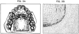
- the tooth form scanning data 32 are obtained by a dental 3D scanner and is outputted, for example, as 3D surface mesh data.
- the tooth form scanning data 32 are a set of triangle polygons.
- stl, ply, off, 3ds and so forth are available as a format of a file for storing the tooth form scanning data 32, various formats uniquely developed by individual enterprises are available.
- dental CAD Computer Aided Design
- CAM Computer Aided Manufacturing
- the computer 10 of the present embodiment acquires information (tooth crown information) regarding a tooth crown from the tooth form scanning data 32 described above.
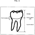
- a “tooth crown” is described with reference to FIG. 4 .
- the tooth crown is a portion appearing outwardly from a tooth ridge and exposed (erupted) in the oral cavity from within the entire tooth.
- a portion of the tooth crown is covered with enamel.
- a portion of the tooth lower than the tooth crown is called “tooth root”
- a boundary line between the tooth crown and the tooth root is called “tooth neck line”.
- the tooth crown database 33 is created by a function (refer to FIG. 1 ) or a process (refer to FIGS. 6 to 21 ) hereinafter described.
- the tooth crown database 33 registers and stores a great amount of tooth crown shape information acquired from an unspecified number of people therein for individual cases, and has a folder (record) for each case, for example, as depicted in FIG. 5 .
- One case corresponds to a set (for one person) of tooth crown portions (tooth crown segments) cut out from the tooth form scanning data 32.
- a folder name capable of specifying a case is applied to each folder.
- a file including tooth crown shape information (vertex group hereinafter described) for each cutout tooth crown portion is stored in each folder (in FIG. 5 , for example, a folder of a folder name of record_000052).
- An FDI number corresponding to a type of a tooth crown (11, 12, 13, 14, ..., and 44 in FIG. 5 ) is applied as a file name to each file.
- the format of each file depicted in FIG. 5 is, for example, ply.
- FIG. 5 depicts an example of a data structure of the tooth crown database 33 in the present embodiment.
- the FDI number is one kind of a symbol for representing information regarding a type of the tooth crown (cutting tooth, molar tooth or the like) and a position of the tooth crown (upper jaw, lower jaw, left or right).
- the FDI number is a number of two digits indicative of a type and a position of a tooth in accordance with a method prescribed by the Fédération Dentaire Internationale (FDI).
- a plantation position of a tooth is indicated by a digit at the tens place, and a type of the tooth is indicated by a digit at the one place.
- the digit "1" at the tens place indicates that the plantation position is the right side of the upper jaw; the digit "2" at the tens place indicates that the plantation position is the left side of the upper jaw; the digit "3" at the tens place indicates that the plantation position is the left side of the lower jaw; and the digit "4" at the tens place indicates that the plantation position is that the plantation position is the right side of the lower jaw.
- the digit "1" at the one place indicates that the type of the tooth is the middle tooth; the digit "2" at the one place indicates that the type of the tooth is the lateral incisor; the digit "3" at the one place indicates that the type of the tooth is the canine tooth; and the digit "4" at the one place indicates that the type of the tooth is the first premolar.
- the digit "5" at the one place indicates that the type of the tooth is the second premolar; the digit "6" at the one place indicates that the type of the tooth is the first molar; the digit "7" at the one place indicates that the type of the tooth is the second molar; and the digit "8" at the one place indicates that the type of the tooth is the third molar.
- the learned neural network information 34 is used when the processing unit 20 functions as the detection point acquisition unit 22 as hereinafter described, and provides a relationship between a type of a tooth crown regarding the tooth crown whose type is specified already and a frequency distribution regarding a normal vector to each vertex that defines a shape of the tooth crown.
- tooth crown shape acquisition unit 21 detection point acquisition unit 22
- tooth crown type estimation unit 23 tooth crown type decision unit 24
- the tooth crown shape acquisition unit 21 acquires a vertex group that defines a tooth crown shape of at least one tooth as tooth crown shape information (tooth crown segment) for specifying the tooth crown portion in the intraoral shape from a plurality of vertexes included in the tooth form scanning data 32 and defining the intraoral shape. Therefore, the tooth crown shape acquisition unit 21 executes processes A1 to A4 described below. It is to be noted that a vertex is a vertex of a triangle polygon (refer to FIG. 3B ), for example, of the tooth form scanning data 32.
- the process A1 is a process for accepting an input of the tooth form scanning data 32.
- the process A2 is a process for acquiring a normal vector or a curvature at each of the plurality of vertexes that are included in the tooth form scanning data 32 accepted by the process A1 and define the intraoral shape.
- the process A3 is a process for extracting, for each tooth, a vertex group defining a tooth crown shape of at least one tooth from the plurality of vertexes on the basis of the normal vectors or the curvatures acquired in the process A2.
- the process A4 is a process for outputting the vertex group extracted for each tooth by the process A3 as tooth crown shape information (tooth crown segment) for specifying a tooth crown portion in the intraoral shape.
- the tooth crown shape acquisition unit 21 may repetitively execute processes A31 and A32 described below by a predetermined number of times (for example, four times) .
- the tooth crown shape acquisition unit 21 replaces the plurality of vertexes with the vertex group obtained by the process A32 in the process A31.
- the tooth crown shape acquisition unit 21 may change a parameter such as a predetermined angle or a predetermined curvature hereinafter described every time the processes A31 and A32 are executed.
- the process A31 is a first coupling process in which, where an angle defined by normal vectors at two vertexes adjacent to each other from among the plurality of vertexes is smaller than a predetermined angle, a process for coupling a segment including one of the two vertexes adjacent to each other and another segment including the other one of the two vertexes adjacent to each other is repetitively executed until a segment to be coupled exists no more.
- the first coupling process A31 may repetitively execute a process for coupling adjacent segments to each other when, as viewed from one of the two vertexes adjacent to each other from among the plurality of vertexes, the curvature at the other vertex is smaller than a predetermined curvature until a segment to be coupled exists no more. It is to be noted that details of the first coupling process A31 are hereinafter described with reference to FIGS. 9A and 9B .
- the process A32 is a second coupling process in which a calculation process of a convex hull, a decision process based on the convex hull and a coupling process of segments are performed.
- a calculation process of a convex hull vertexes included in one segment from among a plurality of segments obtained by the first coupling process A31 are projected on a plane orthogonal to an eruptive direction of the tooth, and a convex hull of the set of the projected vertexes is calculated.
- the decision process based on the convex hull the other segment in which one or more vertexes are included in the calculated convex hull is decided as a segment belonging to a tooth crown same as that to which the one segment belongs.
- the other segment is a segment belonging to a tooth crown same as that to which the one segment belongs
- the one segment and the other segment are coupled and are extracted as a vertex group defining the tooth crown shape of at least one tooth. It is to be noted that details of the second coupling process A32 are hereinafter described with reference to FIGS. 10A to 10C .
- the tooth crown shape acquisition unit 21 may perform the following process as the process A5 .
- the process A5 is a process that deletes a segment if a central position or an average position of the segment obtained by the first coupling process A31 or the second coupling process A32 described hereinabove exists outside a predetermined range in the eruptive direction of the tooth. Where the central position or the average position of the segment exists outside the predetermined range in the eruptive direction of the tooth, it is decided that the segment does not belong to the tooth crown, namely, belongs to the tooth ridge or the like, and the segment is deleted.
- the detection point acquisition unit 22 uniformly selects a predetermined number of vertexes (feature points) from a first vertex set U including a plurality of vertexes to extract a second vertex set A. Then, the detection point acquisition unit 22 estimates a type of a tooth crown including the vertexes (feature points) A[i] of the extracted second vertex set A. Further, the detection point acquisition unit 22 acquires each of the vertexes A[i] belonging to the second vertex set A whose type is estimated as a detection point included in the tooth crown of the type. Therefore, the detection point acquisition unit 22 executes processes B1 to B7 described below. It is to be noted that the first vertex set U indicates, for example, vertexes of all triangle polygons (refer to FIG. 3B ) included in the tooth form scanning data 32.
- the process B1 is a process for accepting an input of the tooth form scanning data 32.
- the process B2 is a process for acquiring a normal vector at each of a plurality of the vertexes that are included in the tooth form scanning data 32 accepted by the process B1 and define an intraoral shape.
- the process B3 is a process for uniformly selecting a predetermined number of vertexes (feature points) as the second vertex set A from the first vertex set U including the plurality of vertexes.
- the process B4 is a process for extracting vertexes that exist within a predetermined distance ⁇ (for example, approximately 3 to 5 mm) according to the size of the tooth from each of the vertexes (feature points) A[i] belonging to the second vertex set A selected by the process B3 as a third vertex set B (A[i]) from within the first vertex set U.
- ⁇ for example, approximately 3 to 5 mm
- the process B5 is a process for calculating a frequency distribution (two-dimensional histogram) regarding the normal vector at each of the vertexes belonging to the third vertex set B (A[i]) extracted by the process B4.
- the process B6 is a process for referring to the storage unit 30 (learned neural network information 34) to decide whether or not each vertex A[i] belonging to the second vertex set A is included in a tooth crown on the basis of the frequency distribution calculated by the process B5 and decide, where it is decided that the vertex A[i] is included in a tooth crown, in what type (FDI number) of a tooth crown the vertex A[i] is included.
- FDI number a relationship between the type of the tooth crown and a frequency distribution regarding normal vectors at the vertexes that define the shape of the tooth crown is stored in advance in the storage unit 30. The relationship is given by a neural network learned already.
- the process B7 is a process for outputting each of the vertexes A[i] whose type (FDI number) is estimated and that belong to the second vertex set A as a detection point included in the tooth crown of the type (FDI number) .
- the detection point acquisition unit 22 may execute processes B51 and B52 described below. It is to be noted that details of the process for calculating a frequency distribution in the process B5 are hereinafter described with reference to FIGS. 14A and 14B .
- the process B51 is a process for determining a local coordinate system regarding the vertexes A[i] belonging to the second vertex set A by main component decomposition of the normal vector at each vertex belonging to the third vertex set B (A[i]).
- the process B52 is a process for calculating a frequency distribution (two-dimensional histogram) regarding the normal vectors at the vertexes belonging to the third vertex set B(A[i]) as a feature amount descriptor at the vertex A[i] belonging to the second vertex set A on the basis of the local coordinate system determined by the process B51.
- the tooth crown type estimation unit 23 overlaps the vertex group acquired as the tooth crown shape information (tooth crown segment) by the tooth crown shape acquisition unit 21 and the detection points (feature points) acquired by the detection point acquisition unit 22 with each other to estimate a type of the tooth crown for each tooth crown.
- the tooth crown type estimation unit 23 calculates, for each tooth crown, a ratio of the number of detection points acquired for each type (each FDI number) to the number of vertexes of the vertex group acquired regarding the tooth crown, and estimates a type of the tooth crown for each crown on the basis of the calculated ratio. Details of such an estimation process of a type of a tooth crown as just described are hereinafter described with reference to FIGS. 16 to 19 .
- the tooth crown type decision unit 24 decides (determines) a type of the tooth crown on the basis of the type (FDI number) of the tooth crown estimated for each tooth crown by the tooth crown type estimation unit 23 and a disposition relationship of the entirety of a plurality of crowns. Further, the tooth crown type decision unit 24 outputs the decided type (FDI number) of the tooth crown together with the tooth crown shape information (tooth crown segment) acquired by the tooth crown shape acquisition unit 21. Details of such a decision process (determination process) of a type of a tooth crown as just described are hereinafter described with reference to FIGS. 20 and 21 .
- steps S1 to S7 are repetitively executed for each of the tooth form scanning data 32 of all cases.
- the tooth form scanning data 32 regarding one case of a processing target is inputted from a dental 3D scanner (not depicted) to the storage unit 30.
- a dental 3D scanner not depicted
- such tooth form scanning data 32 of the upper jaw, lower jaw and abutment tooth as depicted in FIGS. 7A to 7C are stored in the form of an stl file, a ply file or the like, and are read as triangle polygon data into the storage unit 30.
- FIG. 7A is a view depicting an example of the tooth form scanning data 32 of an occlusion state
- FIG. 7B is a view depicting an example of the tooth form scanning data 32 of the upper jaw
- step S1 is a view depicting an example of the tooth form scanning data 32 of the lower jaw and abutment teeth.
- the process at step S1 corresponds to the process A1 by the tooth crown shape acquisition unit 21 and the process B1 by the detection point acquisition unit 22 described hereinabove.
- a point group with a normal line is produced from the tooth form scanning data 32 read in as the triangle polygon data.
- a coordinate value of a point group with a normal line is calculated by substitution of the vertexes of the triangle polygon data.
- a unit normal line vector of a point group with a normal line is calculated by averaging unit normal line vectors of polygons in which the vertexes are factors after a unit normal line vector at each polygon of the triangle polygon data is calculated.
- the process at step S2 corresponds to the process A2 by the tooth crown shape acquisition unit 21 and the process B2 by the detection point acquisition unit 22 described above.
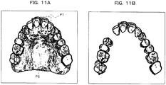
- a process for cutting out only a portion of the tooth crown from the tooth form scanning data 32 of the upper jaw and the lower jaw as depicted in FIGS. 11A and 11B is executed automatically by the function as the tooth crown shape acquisition unit 21.
- Polygons of the portion of the tooth crown acquired by the process at step S3 are called "tooth crown segment".
- the process at step S3 corresponds to the process A3 (including the processes A31 and A32) by the tooth crown shape acquisition unit 21 described hereinabove. Details of the process at step S3 are hereinafter described with reference to FIGS. 8 to 11B .
- the tooth crown segments cut out by the process at step S3 is ideally classified for each tooth crown. However, not only the portion of the tooth crown is cut out as the tooth crown segment by the process at step S3, but there is a case wherein one tooth crown is divided into and cut out as a plurality of tooth crown segments or a location different from the tooth crown (tooth ridge or the like) is outputted as a tooth crown segment. In this case, a type (FDI number) of each tooth crown segment cannot be decided.
- a process for extracting feature points from the tooth form scanning data 32 of the upper jaw or the lower jaw and estimating to the tooth of which FDI number in the tooth form scanning data 32 each feature point belongs is automatically executed by the function as the detection point acquisition unit 22.
- a feature point with regard to which it is estimated that it belongs to a tooth (tooth crown) of a certain FDI number is called "detection point" with regard to the FDI number.
- the process at step S4 corresponds to the processes B3 to B6 (including the processes B51 and B52) by the detection point acquisition unit 22 described hereinabove. Details of the process at step S4 are hereinafter described with reference to FIGS. 12 to 15 .
- process at step S4 may be executed after the process at step S3 is executed or conversely the process at step S3 may be executed after the process at step S4 is executed.
- a process for overlapping the tooth crown segment cut out at step S3 and the detection points of the FDI numbers obtained at step S4 with each other to estimate a candidate for the FDI number of the tooth crown segment is automatically executed by the function as the tooth crown type estimation unit 23.
- a candidate for the FDI number of the tooth crown segment is estimated from a rate (ratio) of the number of detection points of each FDI number to the number of all feature points included in each tooth crown segment.
- a plurality of FDI numbers are estimated as a candidate for the FDI number of the tooth crown segment. Details of the process at step S5 are hereinafter described with reference to FIGS. 16 to 19 .
- a plurality of candidates for the FDI number of the tooth crown segment sometimes exist, and the FDI number of each tooth crown segment is not determined as yet and remains unclear.
- determination of the FDI number of the tooth crown segment is not performed as yet.
- step S6 a process for deciding and finally determining the FDI number of each tooth crown segment from a positional relationship of all tooth crown segments and abutment teeth obtained from the tooth form scanning data 32 of the upper and lower jaws of one case is automatically executed by the function as the tooth crown type decision unit 24.
- allocation of an FDI number to each most likely tooth crown segment when the positional relationship of the entire tooth crown segments obtained from the one tooth form scanning data 32 and the candidates for the FDI number of each tooth crown segment obtained at step S5 are inputted is determined (refer to FIGS. 19 and 21 ). Details of the process at step S6 are hereinafter described with reference to FIGS. 20 and 21 .
- a polygon data file (refer to FIG. 5 ) to which a file name including the FDI number allocated to each tooth crown segment at step S6 is applied is outputted to and registered into a folder (refer to FIG. 5 ) of the case of the processing target in the tooth crown database 33.
- the tooth crown shape information (tooth crown segment, vertex group) cut out at step S3 regarding the tooth crown according to the FDI number of the file name is stored into each polygon data file.
- a cutting out process of a tooth crown (process at step S3 in FIG. 6 ) by the computer 10 (tooth crown shape acquisition unit 21) depicted in FIG. 1 is described with reference to FIGS. 9A to 11B in accordance with a flow chart (steps S11 to S14) depicted in FIG. 8 .
- a process at step S11 corresponds to the processes A1 and A2 by the tooth crown shape acquisition unit 21 described above
- a process at step S14 corresponds to the process A4 by the tooth crown shape acquisition unit 21 described above.
- processes at steps S12 and S13 correspond to the processes A31 and A32 by the tooth crown shape acquisition unit 21 described above and are repetitively executed, for example, by four times while changing a parameter such as a predetermined angle or a predetermined curvature. The number of times of repetition is not limited to four. Further, the processes depicted in FIG. 8 are executed individually for the tooth form scanning data 32 of the upper jaw and the tooth form scanning data 32 of the lower jaw.
- the tooth crown shape acquisition unit 21 acquires a point group with a normal line of the tooth form scanning data 32 regarding a case of a processing target (refer to steps S1 and S2 in FIG. 2 ).
- the point group with a normal line is data, for each point belonging to the point group, having six degrees of freedom between XYZ coordinate values of each point and a unit normal vector at each point.
- step S12 the tooth crown shape acquisition unit 21 executes a region growing segmentation process corresponding to the first coupling process A31 described above as depicted in FIGS. 9A and 9B.
- FIGS. 9A and 9B are views illustrating the region growing segmentation process in the present embodiment.
- such a point group for example, as depicted in FIG. 9A is fragmented into such three segments (small segments hereinafter described) #1, #2 and #3 as depicted in FIG. 9B .
- a vertex denoted by numeral 1 within a circle is included in the segment #1 and another vertex indicated by numeral 2 within a circle is included in the segment #2, and a further vertex indicated by a numeral 3 within a circle is included in the segment #3.
- the threshold value for a curvature (predetermined curvature) and the threshold value for an angle (predetermined angle) may be set or changed in such a manner as described below every time the loop of steps S12 and S13 is repetitively performed four times.
- 0.004, 0.004, 0.004 and 0.020 are set as the threshold values for the curvature (predetermined curvature) at the first to fourth times, respectively.
- the input parameter described above is different depending upon the mesh length (for example, a representative value of a length of one edge of a triangle polygon mesh) of the tooth form scanning data 32, and it is preferable to adjust the input parameter in accordance with the specifications of the dental 3D scanner.
- the mesh length for example, a representative value of a length of one edge of a triangle polygon mesh
- each of the segment groups #1 to #3 depicted in FIG. 9B is called "small segment”.
- the tooth crown shape acquisition unit 21 deletes a small segment that violates the threshold value, and calculates a convex hull of the small segment and performs coupling of the small segments based on the convex hull.
- a process for deleting a small segment that violates the threshold value corresponds to the process at step A5 by the tooth crown shape acquisition unit 21 described above.
- a plane that is estimated as a face nearest to an occlusion surface and is orthogonal to an occlusive direction (eruptive direction of the tooth; Z-axis direction of FIGS. 9 and 10 ) is defined.
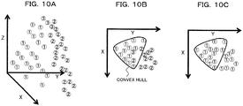
- FIGS. 10A to 10C are views illustrating the convex hull calculation process and the segment coupling process in the present embodiment.
- a numeral 1 within a circle, a numeral 2 within a circle and a numeral 3 within a circle indicate a vertex included in the segment #1, a vertex included in the segment #2 and a vertex included in the segment #3, respectively.
- step S13 such vertexes included in small segments as depicted in FIG. 10A are projected on a plane (XY plane) orthogonal to the occlusive direction (eruptive direction; Z-axis direction) of the teeth as depicted in FIG. 10B .
- a convex hull of a set of vertexes projected on the XY plane in one small segment is calculated.
- a different small segment in which one or more vertexes are included in the calculated convex hull is a segment belonging to a tooth crown same as the tooth crown to which the one small segment belongs.
- the different small segment is a segment that belongs to a tooth crown same as the tooth crown to which the one small segment belongs, the one small segment and the different small segment are coupled to each other and are extracted as a vertex group that define one tooth crown shape.
- the processes at steps S12 and S13 described above are repetitively executed four times as depicted in FIG. 8 . While part of the tooth other than the tooth crown such as the tooth ridge is removed by the first process, approximately 100 small segments are extracted in regard to the tooth crown of one tooth. Then, a coupling process of small segments is repetitively executed by the second to fourth processes and part of the tooth crown is cut out with a higher degree of accuracy.
- condition setting by an input parameter by the region growing segmentation process may be performed so as to obtain a greater tooth crown fragment (tooth crown segment) every time the processes at step S12 and S13 are repetitively executed as described above.
- the input parameter predetermined curvature, predetermined angle or the like
- the input parameter may be set to a predetermined value in advance as described above, or may be set and changed, every time the processes are repetitively executed, automatically or by a manual operation in response to a result of the processes.
- FIG. 11A is a view depicting an example of the tooth form scanning data 32 of the upper jaw or the lower jaw
- FIG. 11B is a view depicting a tooth crown segment cut out by the cutting out process of the present embodiment from the example of the tooth form scanning data 32 depicted in FIG. 11A .
- the tooth crown segment (vertex group) extracted by repetitively executing the processes at steps S12 and S13 is outputted as tooth crown shape information and is stored into the storage unit 30 or the like at step S14.
- the tooth crown segment may be an index to the inputted point group with a normal line or a file including a point group or polygon data.
- an estimation process (process at step S4 in FIG. 6 ) of an FDI number of a feature point by the computer 10 (detection point acquisition unit 22) depicted in FIG. 1 is described with reference to FIGS. 13 to 15 in accordance with a flow chart (steps S21 to S25) depicted in FIG. 12 .
- a process at step S21 corresponds to the processes of the processes B1 and B2 by the detection point acquisition unit 22 described above
- a process at step S22 corresponds to the process B3 by the detection point acquisition unit 22 described above
- a process at step S23 corresponds to the processes B4 and B5 (including processes B51 and B52) by the detection point acquisition unit 22 described above.
- Processes at steps S24 and S25 correspond to the processes B6 and B7 by the detection point acquisition unit 22 described above, respectively. Further, the process depicted in FIG. 12 is executed separately for each of the tooth form scanning data 32 of the upper jaw and the tooth form scanning data 32 of the lower jaw.
- the tooth crown shape acquisition unit 21 acquires a point group with a normal line of the tooth form scanning data 32 regarding a case of a processing target (refer to steps S1 and S2 of FIG. 6 ).
- the point group with a normal line is, for each of points belonging to the point group, data having 6 degrees of freedom of XYZ coordinate values of each point and unit normal line vectors at the individual points.
- the process at step S21 may be common to the process at step S11 depicted in FIG. 8 .
- the detection point acquisition unit 22 performs sampling uniformly (in other words, "thoroughly from the entire region of the set") from the point group U with a normal line (first vertex set) obtained from the tooth form scanning data 32, and selects and extracts a predetermined number of vertexes as feature points (second vertex set A).
- the number of vertexes in the first vertex set U is, for example, approximately 200,000 to 600,000
- the number of vertexes in the second vertex set A (namely, the predetermined number) is, for example, approximately 10,000.
- the feature points extracted here are points that are made a calculation target of a feature amount descriptor at step S23. If a feature amount descriptor is calculated regarding all points in the point group U with a normal line, then the calculation amount increases unnecessarily. Therefore, in the present embodiment, vertexes of a calculation target for a feature amount descriptor are restricted to feature points sampled uniformly from the point group U with a normal line.
- the feature points (points of a black circle in FIG. 13 ) extracted in the present embodiment and the tooth form scanning data 32 of the upper jaw are depicted in an overlapping relationship with each other.
- the detection point acquisition unit 22 calculates a feature amount descriptor (frequency distribution; two-dimensional histogram hereinafter described) for the feature points extracted at step S22.
- a feature amount descriptor frequency distribution; two-dimensional histogram hereinafter described
- a feature amount descriptor is a term used principally in the field of computer vision. While various feature amount descriptors are proposed, a feature amount descriptor in a 3D point group or a 3D surface mesh is described here. It is very difficult for a computer program to interpret data themselves of the 3D point group and the 3D surface mesh, and where is something in a space represented by input data is unknown and the 3D point group and the 3D surface mesh are very difficult to handle. In the 3D point group and the 3D surface mesh, the feature amount descriptor represents local shape information in a compressed manner. An important effect obtained by using the feature amount descriptor is that association of shape information becomes possible.
- a local coordinate system at a point (vertex, feature point) at which the feature amount descriptor is to be calculated is created.
- the tooth form scanning data 32 are data converted in a state in which they are moved and rotated in various directions with respect to an absolute coordinate system, and include noise such as polygon missing and are different in shape among different cases. It is desirable that the local coordinate system is robust against such noise or difference in shape among different cases as described above. For example, where a local coordinate system is created at the top end of the canine tooth, it is desirable to determine the local coordinate system in a similar direction among different cases.
- a method for determining a local coordinate system by main component decomposition of a normal line vector of a point group (third vertex set B(A[i]) described hereinabove) around a point at which the feature amount descriptor is to be calculated is available.
- the main component decomposition is a method for detecting, when a sample set dispersed in a space of a certain dimension number is an input, the direction in which the dispersion is greatest and determining an orthogonal coordinate system using the detected direction as a basis .
- a point group with a normal line existing around a point at which a feature amount descriptor is to be calculated, for example, existing within a predetermined distance ⁇ from the point, is extracted (corresponding to the process B4 described above) .
- the point is the point A[i] described above
- the point group with a normal line existing within the predetermined distance ⁇ from the point A[i] is the third vertex set B(A[i]).
- main component decomposition of the normal line vector at each vertex belonging to the third vertex set B(A[i]) a local coordinate system for the vertexes A[i] belonging to the second vertex set A is determined (corresponding to the process B51 described above).
- the detection point acquisition unit 22 represents the direction of each normal line as viewed from the local coordinate system by a polar coordinate system of ⁇ and ⁇ . Consequently, a two-dimensional histogram (frequency distribution; feature amount descriptor), in which ⁇ and ⁇ are class marks (bin), of the point group with a normal line existing in the predetermined distance ⁇ around each vertex A[i] is calculated, for example, as depicted in FIGS. 14A and 14B (corresponding to the process B52 described hereinabove) . It is to be noted that, in FIGS.
- the axis of abscissa indicates a value (section of the ⁇ - ⁇ coordinate system) when ⁇ and ⁇ are represented in one dimension, and the axis of ordinate indicates a frequency in which a vertex appears in a section of the ⁇ - ⁇ coordinate system.
- the detection point acquisition unit 22 performs an estimation process of an FDI number by the learned neural network for the feature amount descriptor obtained at each feature point (corresponding to the process B6 described above).
- the neural network is one of learning algorithms in which, where there is a pattern when a great number of values of vector data are obtained, the pattern is learned and outputting based on the learned pattern is performed.
- a detector by a neural network that detects and specifies a feature point belonging to a portion of a tooth crown of each FDI number from tooth form scanning data is produced, for example, by the following procedures (i) to (iii) .
- a feature amount descriptor is sometimes calculated in a state in which the portion of the tooth ridge is included at the stage of learning.
- the learned neural network learned on the basis of the feature amount descriptors calculated in a state in which the portion of the tooth ridge is included as described above is used, upon actual detection, it is desirable to input feature amount descriptors calculated by a technique same as the technique used for the feature point descriptors calculated upon learning to the neural network.
- the tooth form scanning data including the point group with a normal line of the portion of the tooth ridge are required.
- a relationship, for each tooth crown whose FDI number is specified, between the FDI number of the tooth crown and a two-dimensional histogram (feature amount descriptor) regarding a normal line vector at each of vertexes that define the tooth crown is stored in advance in the storage unit 30.
- the relationship is given by the learned neural network produced in such a manner as described above, and the information 34 regarding the neural network is stored in advance into the storage unit 30.
- the detection point acquisition unit 22 refers to the storage unit 30 (learned neural network information 34) to decide whether or not each feature point A[i] is included in the tooth crown on the basis of the feature amount descriptor (two-dimensional histogram) calculated at step S23. Then, if it is decided that the feature point A[i] is included in the tooth crown, then the detection point acquisition unit 22 estimates in the tooth crown of which FDI number the feature point A[i] is included.
- each feature point A[i] belonging to the tooth crown of each FDI number is estimated on the basis of the learned neural network, which can detect a feature amount descriptor at a feature point on a tooth crown of each FDI number of the upper and lower jaws with a high probability, and the feature amount descriptor obtained at step S23.
- the neural network used here for example, totaling 12 different neural networks for individually detecting the first of the upper jaw, the second of the upper jaw, the third of the upper jaw, the fourth of the upper jaw, the fifth of the upper jaw, the sixth and seventh of the upper jaw, the first of the lower jaw, the second of the lower jaw, the third of the lower jaw, the fourth of the lower jaw, the fifth of the lower jaw, and the sixth and seventh of the lower jaw are learned and produced separately.
- the neural networks used here individually have, for example, three layers of an inputting layer, an intermediate layer and an outputting layer, and 145 nodes, 100 nodes and 3 nodes are set to the inputting layer, intermediate layer and outputting layer, respectively.
- the feature point A [i] whose FDI number is estimated at step S24 is outputted as a detection point included in the tooth crown of the FDI number and is stored into the storage unit 30 or the like at step S25.
- information regarding the detection point detected for each FDI number is obtained, for example, as depicted in FIG. 15 .
- FIG. 15 is a view depicting the detection points (points of a black circle in FIG. 15 ) of the FDI numbers acquired in the present embodiment in an overlapping relationship with the tooth form scanning data 32 of the upper jaw.
- detection point data regarding a coordinate value of the detection point of each FDI number is sometimes referred to as "detection point”.
- the information regarding the detection point of each FDI number to be outputted may be a file in which coordinate values of the point group are stored or may be an index to an inputted point group with a normal line.
- step S31 to S34 the estimation process (process at step S5 of FIG. 6 ) of an FDI number of a tooth crown segment by the computer 10 (tooth crown type estimation unit 23) depicted in FIG. 1 is described with reference to FIGS. 17 to 19 . It is to be noted that the process depicted in FIG. 16 is executed separately for each of the tooth form scanning data 32 of the upper jaw and the tooth form scanning data 32 of the lower jaw.
- the tooth crown type estimation unit 23 acquires the tooth crown segment outputted at step S14 of FIG. 8 and the detection points of each FDI number outputted at step S25 of FIG. 12 from the storage unit 30 or the like.
- FIG. 17 is a view depicting part of the tooth crown segment cut out from the tooth form scanning data 32 of the upper jaw and the detection points obtained from the tooth form scanning data 32 of the upper jaw in an overlapping relationship with each other.
- Numerals (1 to 6) indicated in FIG. 17 correspond to values of the one place of the FDI numbers of the tooth crowns of the upper jaw.
- positions to which numerals (1 to 6) are applied in FIG. 17 correspond to positions of the detection points of the FDI numbers having the numerals at the one place.
- the numeral 6 corresponds, for example, to the FDI number of the sixth and seventh of the upper jaw depicted in FIG. 15 .
- the tooth crown type estimation unit 23 can overlap the tooth crown segment and the detection points with each other as described above to obtain information regarding in which tooth crown segment the detection point of each FDI number is included. Further, the tooth crown type estimation unit 23 can also acquire information regarding in which tooth crown segment from among the tooth crown segments the feature points extracted at step S22 of FIG. 12 (vertexes belonging to the second vertex set A) are included.
- the tooth crown type estimation unit 23 calculates a vector F for each tooth crown segment in accordance with an expression (1) given below.
- the vector F includes a rate (ratio) of the number of detection points of the FDI numbers in each tooth crown segment to the number of feature points in each tooth crown segment as factors F1, F2, F3, F4, F5 and F67.
- FIGS. 18A to 18C depict particular examples of values of the factors F1, F2, F3, F4, F5 and F67 of the vector F obtained regarding the three types of tooth crown segments.
- the tooth crown type estimation unit 23 estimates a candidate for the FDI number of each tooth crown segment, for example, as described below on the basis of the vector F calculated for each tooth crown segment.
- a candidate for an FDI number number in the one place indicating a type of a tooth
- conditions for estimating a candidate for an FDI number of each tooth crown segment of the lower jaw is set similarly.
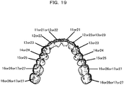
- a particular example of a result (candidate for an FDI number for each tooth crown segment) when the estimation process of an FDI number is performed for the tooth crown segments of the upper jaw is depicted in FIG. 19 .
- a result (candidates for an FDI number) when the estimation process of an FDI number is performed for each tooth crown segment at step S33 is outputted at step S34 and is stored into the storage unit 30 or the like.
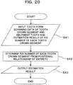
- step S41 to S43 a decision process (process at step S6 of FIG. 6 ) of the FDI number of a tooth crown segment by the computer 10 (tooth crown type decision unit 24) depicted in FIG. 1 is described with reference to FIG. 21 . It is to be noted that the process depicted in FIG. 20 is executed separately for each of the tooth form scanning data 32 of the upper jaw and the tooth form scanning data 32 of the lower jaw.
- the tooth crown type decision unit 24 acquires the tooth form scanning data 32 of the tooth crown segments and the abutment teeth and a result of the estimation of candidates for FDI numbers of the tooth crown segments outputted at step S34 of FIG. 16 , from the storage unit 30 or the like.
- the tooth crown type decision unit 24 calculates a disposition relationship of the entire tooth crowns from the central position of each tooth crown segment and the central position of the tooth form scanning data of the abutment teeth whose FDI number is known in advance, and decides and finally determines an FDI number of each tooth crown segment on the basis of the calculated disposition relationship.
- allocation of the FDI numbers to the tooth crown segments is determined, for example, on the basis of such decision conditions as described just below.
- the tooth crown type decision unit 24 automatically determines allocation of the FDI numbers to the most likely tooth crown segments from a great number of FDI number candidates on the basis of such decision conditions as given above. At this time, by removing candidates other than those of the inputted tooth crown segments from a target of the decision, the determination process of an FDI number can be executed within a practical time period and with a sufficiently high degree of accuracy.
- FIG. 21 A particular example of a result (FDI number for each tooth crown segment) when the decision process of an FDI number is performed for each tooth crown segment of the upper jaw is depicted in FIG. 21 .
- the result of the decision process depicted in FIG. 21 is obtained by performing the decision process described hereinabove for the result of the estimation process depicted in FIG. 19 .
- a result (FDI number of each tooth crown segment) when the decision process of an FDI number is performed for each tooth crown segment at step S42 is outputted and stored into the storage unit 30 or the like at step S43.
- tooth crown portion (tooth crown segment) where a portion other than a tooth crown such as a tooth ridge is removed is cut out accurately and with certainty from the tooth form scanning data 32 of each case.
- each feature point A[i] belonging to the tooth crown of each FDI number is estimated as a detection point on the basis of a learned neural network by which a feature amount descriptor at feature points of the tooth crowns of the FDI numbers of the upper and lower jaws is detected with a high degree of probability and also on the basis of the feature amount descriptor obtained from the tooth form scanning data 32 of a processing target.
- the FDI number of each tooth crown segment in the tooth form scanning data 32 is specified accurately and with certainty on the basis of the tooth crown segment cut out by the tooth crown shape acquisition unit 21 and the detection point of each FDI number obtained by the detection point acquisition unit 22.
- a system for searching for a tooth crown shape can be constructed and data for performing a statistical process of tooth crown shapes for an academic research as a target can be automatically collected. Further, the recognition function and the cutout function of a tooth crown portion in dental CAD software can be implemented, and various working effects can be obtained.
- such a configuration may be applied that, by causing the function as the tooth crown shape acquisition unit 21 described above to locally act on part of the tooth form scanning data 32 of one case, only a portion of the tooth crown clicked by mouse clicking at a portion of the tooth crown or the like is automatically cut out and outputted as data.
- positions of a forward-rearward axis, a leftward-rightward axis, anterior teeth, back teeth and so forth of data (tooth form scanning data 32) regarding an intraoral shape are outputted as data using the function of the detection point acquisition unit 22 described above.
Landscapes
- Health & Medical Sciences (AREA)
- Public Health (AREA)
- Engineering & Computer Science (AREA)
- Epidemiology (AREA)
- General Health & Medical Sciences (AREA)
- Life Sciences & Earth Sciences (AREA)
- Oral & Maxillofacial Surgery (AREA)
- Dentistry (AREA)
- Animal Behavior & Ethology (AREA)
- Veterinary Medicine (AREA)
- Medical Informatics (AREA)
- Data Mining & Analysis (AREA)
- Databases & Information Systems (AREA)
- Biomedical Technology (AREA)
- Pathology (AREA)
- Primary Health Care (AREA)
- Theoretical Computer Science (AREA)
- Computer Vision & Pattern Recognition (AREA)
- Bioinformatics & Computational Biology (AREA)
- Bioinformatics & Cheminformatics (AREA)
- Evolutionary Biology (AREA)
- Evolutionary Computation (AREA)
- Physics & Mathematics (AREA)
- General Engineering & Computer Science (AREA)
- General Physics & Mathematics (AREA)
- Artificial Intelligence (AREA)
- Dental Tools And Instruments Or Auxiliary Dental Instruments (AREA)
Abstract
Description
- The present invention relates to a tooth crown information acquisition program, an information processing apparatus, and a tooth crown information acquisition method.
- Upon dental treatment, a dental technician produces a prosthetic appliance to be filled into a tooth crown in accordance with a request from a dentist. At this time, where a tooth form before the tooth decays is saved in the dental clinic or where a tooth form is sampled before the tooth is shaved as an abutment tooth, a tooth crown shape before shaving of the tooth is available as "preoperative model". In such a case as just described, the dental technician can perform optimization of a contact surface of the prosthetic appliance taking engagement of upper and lower teeth into consideration on the basis of the preoperative model.
- However, the frequency regarding whether or not a preoperative model is available disperses depending upon the dental clinic or the dental laboratory, and it is considered that there are more cases in which a preoperative model is not available than the other cases in which a preoperative model is available. Where no preoperative model is available, the dental technician will perform optimization of a contact face of a prosthetic appliance taking engagement of upper and lower teeth into consideration based on the experience or the skill of the dental technician. It is to be noted that also a technology is available which automatically determine, even if no preoperative model is available, a crown shape based on a unique algorithm.
-
- [Patent Document 1] Japanese Laid-Open Patent Application No.
Hei 09-010231 - [Patent Document 2] Japanese Laid-Open Patent Application No.
2014-512891 - [Patent Document 3] Japanese Laid-Open Patent Application No.
2009-050632 - However, even if a tooth crown shape is determined based on the experience or the skill of the dental technician or a tooth crown shape is determined based on a unique algorithm, it is difficult to make the tooth crown shape of the prosthetic appliance close to the tooth crown shape of the natural tooth. Therefore, it is demanded to make it possible to produce a prosthetic appliance having a more natural shape.
- Therefore, a technology has been proposed by which a tooth crown shape is determined in the following manner. According to the technology, a database (DB) in which tooth form information of an unspecified number of patients is created in advance. When a tooth crown shape of a tooth A of a treatment target of a certain patient is to be determined, a tooth crown shape of a tooth B neighboring with the tooth A is specified and a tooth C of a different patient having a shape similar to the tooth crown shape of the tooth B is searched out from the tooth form information in the DB. Then, a tooth crown shape of a tooth D of the different patient neighboring with the searched out tooth C is determined as a tooth crown shape of the tooth A of the certain patient from within the tooth form information in the DB, and is outputted as a tooth crown shape of a prosthetic appliance for the tooth A.
- In order to make it possible to search for and determine a tooth crown shape as described above, it is demanded to construct a DB in which a tooth crown shape for each tooth and a positional relationship of the teeth are registered in an associated relationship with each other. In the present circumstances, such a DB as described above is constructed by executing, by manual operation, a work for extracting teeth one by one from shape data of teeth each including a tooth and a tooth ridge and another work for registering position information of each extracted tooth (for example, an FDI number of an FDI method (two-digit system)). Accordingly, much labor and much time are required to construct a DB regarding a tooth crown shape of an unspecified number of patients. It is to be noted that FDI is an abbreviation of Fédération Dentaire Internationale.
- According to one aspect of the invention disclosed herein, it is an object of the present invention to implement automatic construction of a database for a tooth crown shape.
- According to one aspect, a tooth crown information acquisition program causes a computer to execute the following processes (1) to (4):
- (1) a process for accepting an input of data relating to an oral cavity shape including a tooth crown shape of at least one tooth;
- (2) a process for acquiring a normal vector or a curvature at each of a plurality of vertexes that are included in the data and define the oral cavity shape;
- (3) a process for extracting a vertex group that defines the tooth crown shape of the at least one tooth from the plurality of vertexes based on the acquired normal vectors or curvatures; and
- (4) a process for outputting the extracted vertex group as tooth crown shape information that specifies a tooth crown portion in the oral cavity shape.
- According to another aspect, a tooth crown information acquisition program causes a computer to execute the following processes (11) to (17):
- (11) a process for accepting an input of data relating to an oral cavity shape;
- (12) a process for acquiring a normal vector at each of a plurality of vertexes that are included in the data and define the oral cavity shape;
- (13) a process for selecting a given number of vertexes uniformly as a second vertex set from within a first vertex set including the plurality of vertexes;
- (14) a process for extracting, from the first vertex set, vertexes existing within a given distance according to a size of the tooth from each vertex belonging to the selected second vertex set, as a third vertex set;
- (15) a process for calculating a frequency distribution relating to the normal vectors at the vertexes belonging to the extracted third vertex set;
- (16) a process for referring to a storage unit that stores, regarding each tooth crown whose type is specified already, a relationship between the type of the tooth crown and a frequency distribution relating to the normal vectors at the vertexes defining the shape of the tooth crown in advance, deciding, based on the calculated frequency distribution, whether or not each vertex belonging to the second vertex set is included in the tooth crown, and estimating, where it is decided that the vertex is included in the tooth crown, in what type of a tooth crown the vertex is included; and
- (17) a process for outputting each of the vertexes that belong to the second vertex set and whose types are estimated as a detection point included in the tooth crown of the type.
- According to the embodiment, automatic construction of a database for a tooth crown shape can be implemented.
-
-
FIG. 1 is a block diagram depicting an example of a functional configuration of an information processing apparatus having a tooth crown information acquisition function as an embodiment of the present invention; -
FIG. 2 is a block diagram depicting an example of a hardware configuration of the information processing apparatus that implements the tooth crown information acquisition function as the embodiment of the present invention; -
FIG. 3A is a view depicting an example of tooth form scanning data (upper jaw), andFIG. 3B is a view depicting tooth form scanning data (triangle polygon data) in an enlarged scale; -
FIG. 4 is a view illustrating a tooth crown; -
FIG. 5 is a view illustrating an example of a data structure of a tooth crown database in the present embodiment; -
FIG. 6 is a flow chart illustrating a tooth crown information acquisition process and a database registration process by the information processing apparatus depicted inFIG. 1 ; -
FIG. 7A is a view depicting an example of tooth form scanning data of an occlusion state;FIG. 7B is a view depicting an example of tooth form scanning data of the upper jaw; andFIG. 7C is a view depicting an example of tooth form scanning data of the lower jaw and abutment teeth; -
FIG. 8 is a flow chart illustrating a cutting out process of a tooth crown by the information processing apparatus (tooth crown shape acquisition unit) depicted inFIG. 1 ; -
FIGS. 9A and 9B are views illustrating a region growing segmentation process (first coupling process) in the present embodiment; -
FIGS. 10A to 10C are views illustrating a convex hull calculation process and a segment coupling process (second coupling process) in the present embodiment; -
FIG. 11A is a view depicting an example of tooth form scanning data of the upper jaw or the lower jaw; andFIG. 11B is a view depicting a tooth crown segment cut out by the cutting out process of the present embodiment from the example of the tooth form scanning data depicted inFIG. 11A ; -
FIG. 12 is a flow chart illustrating an estimation process of an FDI number of a feature point by the information processing apparatus (detection point acquisition unit) depicted inFIG. 1 ; -
FIG. 13 is a view depicting overlapping of feature points extracted and the tooth form scanning data of the upper jaw in the present embodiment; -
FIGS. 14A and 14B are views each illustrating a feature amount descriptor in the present embodiment; -
FIG. 15 is a view depicting detection points of different FDI numbers acquired in the present embodiment in an overlapping relationship with the tooth form scanning data of the upper jaw; -
FIG. 16 is a flow chart illustrating an estimation process of an FDI number of a tooth crown segment by the information processing apparatus (tooth crown type estimation unit) depicted inFIG. 1 ; -
FIG. 17 is a view depicting tooth crown segments cut out in the present embodiment and detection points acquired in the present embodiment in an overlapping relationship with each other; -
FIGS. 18A to 18C are view depicting particular examples of a value of the ratio of the number of detection points of FDI numbers in the tooth crown segments to the number of feature points in the tooth crown segments; -
FIG. 19 is a view depicting a particular example of a result of the estimation process of an FDI number of a tooth crown segment in the present embodiment; -
FIG. 20 is a flow chart illustrating a decision process of an FDI number of a tooth crown segment by the information processing apparatus (tooth crown type decision unit) depicted inFIG. 1 ; and -
FIG. 21 is a view depicting a particular example of a result of the decision process of an FDI number of a tooth crown segment in the present embodiment. - In the following, embodiments of a tooth crown information acquisition program, an information processing apparatus and a tooth crown information acquisition method disclosed herein are described in detail with reference to the drawings. It is to be noted that the embodiments described below are illustrative to the end, and there is no intention to eliminate various modifications and applications of the technology not specified in the embodiments. In other words, variations and modifications can be made without departing from the scope of the present invention. Further, it is not intended that the drawings include only the components depicted therein but can include other functions. Further, the embodiments can be suitably combined with each other without departing from the scope in which processing contents are not inconsistent with each other.
- First, a hardware configuration of an information processing apparatus (computer) 10 that implements a tooth crown information acquisition function of the present embodiment is described with reference to
FIG. 2. FIG. 2 is a block diagram depicting an example of the hardware configuration. - The
computer 10 includes, for example, as components, aprocessor 11, a RAM (Random Access Memory) 12, an HDD (Hard Disk Drive) 13, agraphic processing apparatus 14, an inputtinginterface 15, anoptical drive apparatus 16, adevice coupling interface 17 and anetwork interface 18. Thecomponents 11 to 18 are configured for communication with each other through abus 19. - The processor (processing unit) 11 controls the
entire computer 10. Theprocessor 11 may be a multiprocessor. Theprocessor 11 may be one of, for example, a CPU (Central Processing Unit), an MPU (Micro Processing Unit), a DSP (Digital Signal Processor), an ASIC (Application Specific Integrated Circuit), a PLD (Programmable Logic Device) and an FPGA (Field Programmable Gate Array) . Or, theprocessor 11 may be a combination of two or more of a CPU, an MPU, a DSP, an ASIC, a PLD and an FPGA. - The RAM (storage unit) 12 is used as a main storage apparatus of the
computer 10. At least one of an OS (Operating System) program and an application program to be executed by theprocessor 11 is stored temporarily in theRAM 12. Further, various data to be used for processing by theprocessor 11 are stored in theRAM 12. The application program may include a tooth crown information acquisition program (refer toreference numeral 31 ofFIG. 1 ) that is executed by theprocessor 11 to implement the tooth crown information acquisition function of the present embodiment by thecomputer 10. - The HDD (storage unit) 13 magnetically performs writing and readout of data into and from a built-in disk. The
HDD 13 is used as an auxiliary storage apparatus of thecomputer 10. The OS program, application programs and various data are stored in theHDD 13. It is to be noted that, as an auxiliary storage apparatus, also a semiconductor storage device (solid state drive: SSD) such as a flash memory can be used. - A
monitor 14a is coupled to thegraphic processing apparatus 14. Thegraphic processing apparatus 14 causes themonitor 14a to display an image on a screen of themonitor 14a in accordance with a command from theprocessor 11. As themonitor 14a, a display apparatus for which a CRT (Cathode Ray Tube) is used, a liquid crystal displaying apparatus and so forth are available. - A
keyboard 15a and amouse 15b are coupled to the inputtinginterface 15. The inputtinginterface 15 transmits a signal sent thereto from thekeyboard 15a or themouse 15b to theprocessor 11. It is to be noted that themouse 15b is an example of a pointing device and also some other pointing device can be used. As a different pointing device, a touch panel, a tablet, a touchpad, a trackball and so forth available. - The
optical drive apparatus 16 performs reading of data recorded on anoptical disk 16a utilizing laser light or the like. Theoptical disk 16a is a portable type non-transitory storage medium on which data is recorded for reading by reflection of light. As theoptical disk 16a, a DVD (Digital Versatile Disk), a DVD-RAM, a CD-ROM (Compact Disk Dead Only Memory), a CD-R (Recordable) /RW (ReWritable) and so forth are available. - The
device coupling interface 17 is a communication interface for coupling peripheral equipment to thecomputer 10. For example, amemory device 17a or a memory reader/writer 17b can be coupled to thedevice coupling interface 17. Thememory device 17a is a non-transitory recording medium in which a communication function with thedevice coupling interface 17 is incorporated, such as, for example, a USB (Universal Serial Bus) memory. The memory reader/writer 17b performs writing of data into amemory card 17c or reading out of data from thememory card 17c. Thememory card 17c is a card type non-transitory recording medium. - The
network interface 18 is coupled to anetwork 18a. Thenetwork interface 18 performs transmission and reception of data to and from a different computer or communication equipment through thenetwork 18a. - By the
computer 10 having such a hardware configuration as described, the tooth crown information acquisition function of the present embodiment hereinafter described with reference toFIGS. 6 to 21 can be implemented. - It is to be noted that the
computer 10 implements the tooth crown information acquisition function of the present embodiment by executing a program (tooth crown information acquisition program or the like) recorded, for example, on a computer-readable non-transitory recording medium. A program in which processing contents to be executed by thecomputer 10 are described can be recorded in various recording media. For example, a program to be executed by thecomputer 10 can be stored in theHDD 13. Theprocessor 11 loads at least part of the program in theHDD 13 into theRAM 12 and executes the loaded program. - Further, a program to be executed by the computer 10 (processor 11) can be recorded also on a non-transitory portable recording medium such as an
optical disk 16a, amemory device 17a or amemory card 17c. The program stored in the portable recording medium can be executed after installation into theHDD 13, for example, under the control of theprocessor 11. Further, theprocessor 11 can directly read out the program from the portable recording medium and execute the program. - Now, a functional configuration of the information processing apparatus (computer) 10 having the tooth crown information acquisition function of the present embodiment is described with reference to
FIG. 1. FIG. 1 is a block diagram depicting an example of the functional configuration. - The
computer 10 implements a function for acquiring tooth crown information from data (hereinafter referred to as tooth form scanning data) 32 regarding an intraoral shape, which is obtained by a three-dimensional (3D) dental scanner and includes a tooth crown shape of at least one tooth, and automatically creating atooth crown database 33. To this end, as depicted inFIG. 1 , thecomputer 10 has functions at least as aprocessing unit 20, astorage unit 30, an inputtingunit 40 and a displayingunit 50. - The
processing unit 20 is such aprocessor 11, for example, as depicted inFIG. 2 , and implements, by executing the tooth crowninformation acquisition program 31 described above, functions as a tooth crownshape acquisition unit 21, a detectionpoint acquisition unit 22, a tooth crowntype estimation unit 23 and a tooth crowntype decision unit 24. - The
storage unit 30 is such aRAM 12 or anHDD 13, for example, as depicted inFIG. 2 , and stores and preserves various kinds of information for implementing the tooth crown information acquisition function. As the various kinds of information, not only the tooth crowninformation acquisition program 31, but also the toothform scanning data 32, thetooth crown database 33, learnedneural network information 34 and so forth are included. - The inputting
unit 40 is such as akeyboard 15a and amouse 15b, for example, as depicted inFIG. 2 , and is operated by the user such that various instructions for acquiring tooth crown information are issued. It is to be noted that a touch panel, a tablet, a touch pad, a trackball or the like may be used in place of themouse 15b. - The displaying
unit 50 is such as amonitor 14a, for example, as depicted inFIG. 2 , and displays various situations involved in an acquisition process when the user acquires tooth crown information using thecomputer 10 of the present embodiment. - As described above, the tooth crown
information acquisition program 31 causes the processing unit 20 (processor 11) to execute processes by the tooth crownshape acquisition unit 21, detectionpoint acquisition unit 22, tooth crowntype estimation unit 23 and tooth crowntype decision unit 24 hereinafter described. - As depicted in
FIG. 3A , the toothform scanning data 32 are obtained by a dental 3D scanner and is outputted, for example, as 3D surface mesh data. For example, as depicted inFIG. 3B , the toothform scanning data 32 are a set of triangle polygons. Although stl, ply, off, 3ds and so forth are available as a format of a file for storing the toothform scanning data 32, various formats uniquely developed by individual enterprises are available. Where dental CAD (Computer Aided Design)/CAM (Computer Aided Manufacturing) is operated in a dental laboratory or a dental clinic, such toothform scanning data 32 as described above are accumulated as tooth form information of an unspecified number of people by a dental 3D scanner. It is to be noted that an example (upper jaw) of the toothform scanning data 32 is depicted inFIG. 3A and triangular polygon data of the toothform scanning data 32 are depicted in an enlarged scale inFIG. 3B . - The
computer 10 of the present embodiment acquires information (tooth crown information) regarding a tooth crown from the toothform scanning data 32 described above. Here, a "tooth crown" is described with reference toFIG. 4 . As depicted inFIG. 4 , the tooth crown is a portion appearing outwardly from a tooth ridge and exposed (erupted) in the oral cavity from within the entire tooth. In the human being, a portion of the tooth crown is covered with enamel. A portion of the tooth lower than the tooth crown is called "tooth root", and a boundary line between the tooth crown and the tooth root is called "tooth neck line". - The
tooth crown database 33 is created by a function (refer toFIG. 1 ) or a process (refer toFIGS. 6 to 21 ) hereinafter described. Thetooth crown database 33 registers and stores a great amount of tooth crown shape information acquired from an unspecified number of people therein for individual cases, and has a folder (record) for each case, for example, as depicted inFIG. 5 . One case corresponds to a set (for one person) of tooth crown portions (tooth crown segments) cut out from the toothform scanning data 32. A folder name capable of specifying a case (inFIG. 5 , for example, record_000024, record_000025, ..., record_000055) is applied to each folder. Further, a file including tooth crown shape information (vertex group hereinafter described) for each cutout tooth crown portion is stored in each folder (inFIG. 5 , for example, a folder of a folder name of record_000052). An FDI number corresponding to a type of a tooth crown (11, 12, 13, 14, ..., and 44 inFIG. 5 ) is applied as a file name to each file. It is to be noted that the format of each file depicted inFIG. 5 is, for example, ply.FIG. 5 depicts an example of a data structure of thetooth crown database 33 in the present embodiment. - Here, the FDI number is one kind of a symbol for representing information regarding a type of the tooth crown (cutting tooth, molar tooth or the like) and a position of the tooth crown (upper jaw, lower jaw, left or right). The FDI number is a number of two digits indicative of a type and a position of a tooth in accordance with a method prescribed by the Fédération Dentaire Internationale (FDI). A plantation position of a tooth is indicated by a digit at the tens place, and a type of the tooth is indicated by a digit at the one place.
- In particular, the digit "1" at the tens place indicates that the plantation position is the right side of the upper jaw; the digit "2" at the tens place indicates that the plantation position is the left side of the upper jaw; the digit "3" at the tens place indicates that the plantation position is the left side of the lower jaw; and the digit "4" at the tens place indicates that the plantation position is that the plantation position is the right side of the lower jaw. Further, the digit "1" at the one place indicates that the type of the tooth is the middle tooth; the digit "2" at the one place indicates that the type of the tooth is the lateral incisor; the digit "3" at the one place indicates that the type of the tooth is the canine tooth; and the digit "4" at the one place indicates that the type of the tooth is the first premolar. Similarly, the digit "5" at the one place indicates that the type of the tooth is the second premolar; the digit "6" at the one place indicates that the type of the tooth is the first molar; the digit "7" at the one place indicates that the type of the tooth is the second molar; and the digit "8" at the one place indicates that the type of the tooth is the third molar.
- The learned
neural network information 34 is used when theprocessing unit 20 functions as the detectionpoint acquisition unit 22 as hereinafter described, and provides a relationship between a type of a tooth crown regarding the tooth crown whose type is specified already and a frequency distribution regarding a normal vector to each vertex that defines a shape of the tooth crown. - Now, functions as the tooth crown
shape acquisition unit 21, detectionpoint acquisition unit 22, tooth crowntype estimation unit 23 and tooth crowntype decision unit 24 implemented by the processing unit 20 (processor 11) are described. - The tooth crown
shape acquisition unit 21 acquires a vertex group that defines a tooth crown shape of at least one tooth as tooth crown shape information (tooth crown segment) for specifying the tooth crown portion in the intraoral shape from a plurality of vertexes included in the toothform scanning data 32 and defining the intraoral shape. Therefore, the tooth crownshape acquisition unit 21 executes processes A1 to A4 described below. It is to be noted that a vertex is a vertex of a triangle polygon (refer toFIG. 3B ), for example, of the toothform scanning data 32. - The process A1 is a process for accepting an input of the tooth
form scanning data 32. - The process A2 is a process for acquiring a normal vector or a curvature at each of the plurality of vertexes that are included in the tooth
form scanning data 32 accepted by the process A1 and define the intraoral shape. - The process A3 is a process for extracting, for each tooth, a vertex group defining a tooth crown shape of at least one tooth from the plurality of vertexes on the basis of the normal vectors or the curvatures acquired in the process A2.
- The process A4 is a process for outputting the vertex group extracted for each tooth by the process A3 as tooth crown shape information (tooth crown segment) for specifying a tooth crown portion in the intraoral shape.
- When a vertex group is extracted for each tooth by the process A3, the tooth crown
shape acquisition unit 21 may repetitively execute processes A31 and A32 described below by a predetermined number of times (for example, four times) . In this case, the tooth crownshape acquisition unit 21 replaces the plurality of vertexes with the vertex group obtained by the process A32 in the process A31. Or, the tooth crownshape acquisition unit 21 may change a parameter such as a predetermined angle or a predetermined curvature hereinafter described every time the processes A31 and A32 are executed. - The process A31 is a first coupling process in which, where an angle defined by normal vectors at two vertexes adjacent to each other from among the plurality of vertexes is smaller than a predetermined angle, a process for coupling a segment including one of the two vertexes adjacent to each other and another segment including the other one of the two vertexes adjacent to each other is repetitively executed until a segment to be coupled exists no more. In place of this, the first coupling process A31 may repetitively execute a process for coupling adjacent segments to each other when, as viewed from one of the two vertexes adjacent to each other from among the plurality of vertexes, the curvature at the other vertex is smaller than a predetermined curvature until a segment to be coupled exists no more. It is to be noted that details of the first coupling process A31 are hereinafter described with reference to
FIGS. 9A and 9B . - The process A32 is a second coupling process in which a calculation process of a convex hull, a decision process based on the convex hull and a coupling process of segments are performed. Here, in the calculation process of a convex hull, vertexes included in one segment from among a plurality of segments obtained by the first coupling process A31 are projected on a plane orthogonal to an eruptive direction of the tooth, and a convex hull of the set of the projected vertexes is calculated. In the decision process based on the convex hull, the other segment in which one or more vertexes are included in the calculated convex hull is decided as a segment belonging to a tooth crown same as that to which the one segment belongs. When it is decided that the other segment is a segment belonging to a tooth crown same as that to which the one segment belongs, in the coupling process of the segments, the one segment and the other segment are coupled and are extracted as a vertex group defining the tooth crown shape of at least one tooth. It is to be noted that details of the second coupling process A32 are hereinafter described with reference to
FIGS. 10A to 10C . - It is to be noted that the tooth crown
shape acquisition unit 21 may perform the following process as the process A5 . In particular, the process A5 is a process that deletes a segment if a central position or an average position of the segment obtained by the first coupling process A31 or the second coupling process A32 described hereinabove exists outside a predetermined range in the eruptive direction of the tooth. Where the central position or the average position of the segment exists outside the predetermined range in the eruptive direction of the tooth, it is decided that the segment does not belong to the tooth crown, namely, belongs to the tooth ridge or the like, and the segment is deleted. - The detection
point acquisition unit 22 uniformly selects a predetermined number of vertexes (feature points) from a first vertex set U including a plurality of vertexes to extract a second vertex set A. Then, the detectionpoint acquisition unit 22 estimates a type of a tooth crown including the vertexes (feature points) A[i] of the extracted second vertex set A. Further, the detectionpoint acquisition unit 22 acquires each of the vertexes A[i] belonging to the second vertex set A whose type is estimated as a detection point included in the tooth crown of the type. Therefore, the detectionpoint acquisition unit 22 executes processes B1 to B7 described below. It is to be noted that the first vertex set U indicates, for example, vertexes of all triangle polygons (refer toFIG. 3B ) included in the toothform scanning data 32. - The process B1 is a process for accepting an input of the tooth
form scanning data 32. - The process B2 is a process for acquiring a normal vector at each of a plurality of the vertexes that are included in the tooth
form scanning data 32 accepted by the process B1 and define an intraoral shape. - The process B3 is a process for uniformly selecting a predetermined number of vertexes (feature points) as the second vertex set A from the first vertex set U including the plurality of vertexes.
- The process B4 is a process for extracting vertexes that exist within a predetermined distance δ (for example, approximately 3 to 5 mm) according to the size of the tooth from each of the vertexes (feature points) A[i] belonging to the second vertex set A selected by the process B3 as a third vertex set B (A[i]) from within the first vertex set U.
- The process B5 is a process for calculating a frequency distribution (two-dimensional histogram) regarding the normal vector at each of the vertexes belonging to the third vertex set B (A[i]) extracted by the process B4.
- The process B6 is a process for referring to the storage unit 30 (learned neural network information 34) to decide whether or not each vertex A[i] belonging to the second vertex set A is included in a tooth crown on the basis of the frequency distribution calculated by the process B5 and decide, where it is decided that the vertex A[i] is included in a tooth crown, in what type (FDI number) of a tooth crown the vertex A[i] is included. For a tooth crown whose type is specified already, a relationship between the type of the tooth crown and a frequency distribution regarding normal vectors at the vertexes that define the shape of the tooth crown is stored in advance in the
storage unit 30. The relationship is given by a neural network learned already. - The process B7 is a process for outputting each of the vertexes A[i] whose type (FDI number) is estimated and that belong to the second vertex set A as a detection point included in the tooth crown of the type (FDI number) .
- When the frequency distribution (two-dimensional histogram) is calculated by the process B5, the detection
point acquisition unit 22 may execute processes B51 and B52 described below. It is to be noted that details of the process for calculating a frequency distribution in the process B5 are hereinafter described with reference toFIGS. 14A and 14B . - The process B51 is a process for determining a local coordinate system regarding the vertexes A[i] belonging to the second vertex set A by main component decomposition of the normal vector at each vertex belonging to the third vertex set B (A[i]).
- The process B52 is a process for calculating a frequency distribution (two-dimensional histogram) regarding the normal vectors at the vertexes belonging to the third vertex set B(A[i]) as a feature amount descriptor at the vertex A[i] belonging to the second vertex set A on the basis of the local coordinate system determined by the process B51.
- The tooth crown
type estimation unit 23 overlaps the vertex group acquired as the tooth crown shape information (tooth crown segment) by the tooth crownshape acquisition unit 21 and the detection points (feature points) acquired by the detectionpoint acquisition unit 22 with each other to estimate a type of the tooth crown for each tooth crown. At this time, the tooth crowntype estimation unit 23 calculates, for each tooth crown, a ratio of the number of detection points acquired for each type (each FDI number) to the number of vertexes of the vertex group acquired regarding the tooth crown, and estimates a type of the tooth crown for each crown on the basis of the calculated ratio. Details of such an estimation process of a type of a tooth crown as just described are hereinafter described with reference toFIGS. 16 to 19 . - The tooth crown
type decision unit 24 decides (determines) a type of the tooth crown on the basis of the type (FDI number) of the tooth crown estimated for each tooth crown by the tooth crowntype estimation unit 23 and a disposition relationship of the entirety of a plurality of crowns. Further, the tooth crowntype decision unit 24 outputs the decided type (FDI number) of the tooth crown together with the tooth crown shape information (tooth crown segment) acquired by the tooth crownshape acquisition unit 21. Details of such a decision process (determination process) of a type of a tooth crown as just described are hereinafter described with reference toFIGS. 20 and21 . - Now, action of the
computer 10 of the present embodiment having the tooth crown information acquisition function described above is described with reference toFIGS. 6 to 21 . - First, a flow of the entire process (tooth crown information acquisition process and database registration process) by the computer (information processing apparatus) 10 depicted in
FIG. 1 is described with reference to a flow chart (steps S1 to S7) depicted inFIG. 6 . Processes at steps S1 to S7 are repetitively executed for each of the toothform scanning data 32 of all cases. - At step S1, the tooth
form scanning data 32 regarding one case of a processing target is inputted from a dental 3D scanner (not depicted) to thestorage unit 30. At this time, such toothform scanning data 32 of the upper jaw, lower jaw and abutment tooth as depicted inFIGS. 7A to 7C are stored in the form of an stl file, a ply file or the like, and are read as triangle polygon data into thestorage unit 30. It is to be noted thatFIG. 7A is a view depicting an example of the toothform scanning data 32 of an occlusion state;FIG. 7B is a view depicting an example of the toothform scanning data 32 of the upper jaw; andFIG. 7C is a view depicting an example of the toothform scanning data 32 of the lower jaw and abutment teeth. The process at step S1 corresponds to the process A1 by the tooth crownshape acquisition unit 21 and the process B1 by the detectionpoint acquisition unit 22 described hereinabove. - At step S2, a point group with a normal line is produced from the tooth
form scanning data 32 read in as the triangle polygon data. A coordinate value of a point group with a normal line is calculated by substitution of the vertexes of the triangle polygon data. Further, a unit normal line vector of a point group with a normal line is calculated by averaging unit normal line vectors of polygons in which the vertexes are factors after a unit normal line vector at each polygon of the triangle polygon data is calculated. The process at step S2 corresponds to the process A2 by the tooth crownshape acquisition unit 21 and the process B2 by the detectionpoint acquisition unit 22 described above. - At step S3, a process for cutting out only a portion of the tooth crown from the tooth
form scanning data 32 of the upper jaw and the lower jaw as depicted inFIGS. 11A and 11B is executed automatically by the function as the tooth crownshape acquisition unit 21. Polygons of the portion of the tooth crown acquired by the process at step S3 are called "tooth crown segment". The process at step S3 corresponds to the process A3 (including the processes A31 and A32) by the tooth crownshape acquisition unit 21 described hereinabove. Details of the process at step S3 are hereinafter described with reference toFIGS. 8 to 11B . - The tooth crown segments cut out by the process at step S3 is ideally classified for each tooth crown. However, not only the portion of the tooth crown is cut out as the tooth crown segment by the process at step S3, but there is a case wherein one tooth crown is divided into and cut out as a plurality of tooth crown segments or a location different from the tooth crown (tooth ridge or the like) is outputted as a tooth crown segment. In this case, a type (FDI number) of each tooth crown segment cannot be decided.
- At step S4, a process for extracting feature points from the tooth
form scanning data 32 of the upper jaw or the lower jaw and estimating to the tooth of which FDI number in the toothform scanning data 32 each feature point belongs is automatically executed by the function as the detectionpoint acquisition unit 22. A feature point with regard to which it is estimated that it belongs to a tooth (tooth crown) of a certain FDI number is called "detection point" with regard to the FDI number. The process at step S4 corresponds to the processes B3 to B6 (including the processes B51 and B52) by the detectionpoint acquisition unit 22 described hereinabove. Details of the process at step S4 are hereinafter described with reference toFIGS. 12 to 15 . - It is to be noted that, while the processes at steps S3 and S4 are executed in parallel in
FIG. 6 , the process at step S4 may be executed after the process at step S3 is executed or conversely the process at step S3 may be executed after the process at step S4 is executed. - At step S5, a process for overlapping the tooth crown segment cut out at step S3 and the detection points of the FDI numbers obtained at step S4 with each other to estimate a candidate for the FDI number of the tooth crown segment is automatically executed by the function as the tooth crown
type estimation unit 23. At this time, a candidate for the FDI number of the tooth crown segment is estimated from a rate (ratio) of the number of detection points of each FDI number to the number of all feature points included in each tooth crown segment. At this time, there is a case in which a plurality of FDI numbers are estimated as a candidate for the FDI number of the tooth crown segment. Details of the process at step S5 are hereinafter described with reference toFIGS. 16 to 19 . - At a point of time at which the estimation process at step S5 is completed, a plurality of candidates for the FDI number of the tooth crown segment sometimes exist, and the FDI number of each tooth crown segment is not determined as yet and remains unclear. In particular, although narrowing down of the FDI number for each tooth crown segment is performed at step S5, determination of the FDI number of the tooth crown segment is not performed as yet.
- Therefore, at step S6, a process for deciding and finally determining the FDI number of each tooth crown segment from a positional relationship of all tooth crown segments and abutment teeth obtained from the tooth
form scanning data 32 of the upper and lower jaws of one case is automatically executed by the function as the tooth crowntype decision unit 24. In particular, at step S6, allocation of an FDI number to each most likely tooth crown segment when the positional relationship of the entire tooth crown segments obtained from the one toothform scanning data 32 and the candidates for the FDI number of each tooth crown segment obtained at step S5 are inputted is determined (refer toFIGS. 19 and21 ). Details of the process at step S6 are hereinafter described with reference toFIGS. 20 and21 . - At step S7, a polygon data file (refer to
FIG. 5 ) to which a file name including the FDI number allocated to each tooth crown segment at step S6 is applied is outputted to and registered into a folder (refer toFIG. 5 ) of the case of the processing target in thetooth crown database 33. The tooth crown shape information (tooth crown segment, vertex group) cut out at step S3 regarding the tooth crown according to the FDI number of the file name is stored into each polygon data file. - The processes at steps S1 to S7 described above are repetitively executed for the tooth
form scanning data 32 of all cases. Consequently, for example, such atooth crown database 33 as depicted inFIG. 5 is created, and the tooth crown shape information (polygon data file) of the cases is registered into thetooth crown database 33. - Now, a cutting out process of a tooth crown (process at step S3 in
FIG. 6 ) by the computer 10 (tooth crown shape acquisition unit 21) depicted inFIG. 1 is described with reference toFIGS. 9A to 11B in accordance with a flow chart (steps S11 to S14) depicted inFIG. 8 . It is to be noted that a process at step S11 corresponds to the processes A1 and A2 by the tooth crownshape acquisition unit 21 described above, and a process at step S14 corresponds to the process A4 by the tooth crownshape acquisition unit 21 described above. Further, processes at steps S12 and S13 correspond to the processes A31 and A32 by the tooth crownshape acquisition unit 21 described above and are repetitively executed, for example, by four times while changing a parameter such as a predetermined angle or a predetermined curvature. The number of times of repetition is not limited to four. Further, the processes depicted inFIG. 8 are executed individually for the toothform scanning data 32 of the upper jaw and the toothform scanning data 32 of the lower jaw. - First, at step S11, the tooth crown
shape acquisition unit 21 acquires a point group with a normal line of the toothform scanning data 32 regarding a case of a processing target (refer to steps S1 and S2 inFIG. 2 ). The point group with a normal line is data, for each point belonging to the point group, having six degrees of freedom between XYZ coordinate values of each point and a unit normal vector at each point. - Thereafter, at step S12, the tooth crown
shape acquisition unit 21 executes a region growing segmentation process corresponding to the first coupling process A31 described above as depicted inFIGS. 9A and 9B. FIGS. 9A and 9B are views illustrating the region growing segmentation process in the present embodiment. - In the region growing segmentation, first, all points of the point group with a normal line acquired from the tooth
form scanning data 32 of one case are registered as points belonging one by one to different segments. Thereafter, when a certain point X is noticed, a point Y adjacent to the point X is referred to. Then, if the curvature at the point Y is smaller than a predetermined curvature or if the angle defined by a normal line vector at the point Y and a normal line vector at the point X is smaller than a predetermined angle, then it is decided that the point X is smoothly coupled with the adjacent point Y. In this case, a segment including the point X and another segment including the adjacent point Y are coupled to each other. Such a coupling process as just described is repetitively executed until a segment to be coupled no more exists. - By performing such a region growing segmentation process as described above, such a point group, for example, as depicted in
FIG. 9A is fragmented into such three segments (small segments hereinafter described) #1, #2 and #3 as depicted inFIG. 9B . InFIG. 9B , a vertex denoted bynumeral 1 within a circle is included in thesegment # 1 and another vertex indicated bynumeral 2 within a circle is included in thesegment # 2, and a further vertex indicated by anumeral 3 within a circle is included in thesegment # 3. - When the region growing segmentation process is performed for the tooth
form scanning data 32 as described above, it is desired to suitably set a predetermined curvature or a predetermined angle, which is to be used as a threshold value for deciding whether or not vertexes adjacent to each other are smoothly coupled to each other, as an input parameter. In the process depicted inFIG. 8 , the threshold value for a curvature (predetermined curvature) and the threshold value for an angle (predetermined angle) may be set or changed in such a manner as described below every time the loop of steps S12 and S13 is repetitively performed four times. For example, 0.004, 0.004, 0.004 and 0.020 are set as the threshold values for the curvature (predetermined curvature) at the first to fourth times, respectively. When decision is performed on the basis of the angle formed by normal line vectors at two points adjacent to each other, an angle of 5 degrees is set as the threshold value for the angle (predetermined angle) for the first to fourth times. - The input parameter described above is different depending upon the mesh length (for example, a representative value of a length of one edge of a triangle polygon mesh) of the tooth
form scanning data 32, and it is preferable to adjust the input parameter in accordance with the specifications of the dental 3D scanner. - It is to be noted that the point group with a normal line fragmentized by the process at step S12, for example, each of the
segment groups # 1 to #3 depicted inFIG. 9B , is called "small segment". - At step S13, the tooth crown
shape acquisition unit 21 deletes a small segment that violates the threshold value, and calculates a convex hull of the small segment and performs coupling of the small segments based on the convex hull. - A process for deleting a small segment that violates the threshold value corresponds to the process at step A5 by the tooth crown
shape acquisition unit 21 described above. In this process, a plane that is estimated as a face nearest to an occlusion surface and is orthogonal to an occlusive direction (eruptive direction of the tooth; Z-axis direction ofFIGS. 9 and10 ) is defined. Where an average position or a central position of the Z coordinates of vertexes belonging to a small segment exists at a position (position outside a predetermined range) spaced away by a predetermined distance or more in the occlusive direction from the plane, it is decided that the small segment is outside the processing target (for example, belongs to the tooth ridge or the like) and the small segment is deleted from the processing target. - The convex hull calculation process and segment coupling process at step S13 correspond to the second coupling process A32 by the tooth crown
shape acquisition unit 21 described hereinabove and are executed in such a manner as depicted inFIGS. 10A to 10C. FIGS. 10A to 10C are views illustrating the convex hull calculation process and the segment coupling process in the present embodiment. Similarly as inFIG. 9B , inFIGS. 10A to 10C , anumeral 1 within a circle, anumeral 2 within a circle and anumeral 3 within a circle indicate a vertex included in thesegment # 1, a vertex included in thesegment # 2 and a vertex included in thesegment # 3, respectively. - Only if the region growing segmentation process is performed simply, it is sometimes difficult to cut out a tooth crown smoothly from the tooth
crown scanning data 32. For example, the cheek side and the tongue side of a tooth crown are frequently fragmentized such that they are included in different small segments, and a great number of small segments are generated especially at the occlusion surface side of the molar. Therefore, it is preferable to perform a process for coupling small segments for each tooth crown. - Therefore, at step S13, such vertexes included in small segments as depicted in
FIG. 10A are projected on a plane (XY plane) orthogonal to the occlusive direction (eruptive direction; Z-axis direction) of the teeth as depicted inFIG. 10B . Thereafter, as depicted inFIG. 10B , a convex hull of a set of vertexes projected on the XY plane in one small segment is calculated. Then, it is decided that a different small segment in which one or more vertexes are included in the calculated convex hull is a segment belonging to a tooth crown same as the tooth crown to which the one small segment belongs. Where it is decided that the different small segment is a segment that belongs to a tooth crown same as the tooth crown to which the one small segment belongs, the one small segment and the different small segment are coupled to each other and are extracted as a vertex group that define one tooth crown shape. - For example, in
FIG. 10B , all of projection images of vertexes (numeral 3 within a circle) belonging to thesmall segment # 3 are included in the convex hull calculated in regard to a projection image of vertexes (numeral 1 within a circle) belonging to thesmall segment # 1. Further, part of projection images of vertexes (numeral 2 within a circle) belonging to thesmall segment # 2 are included in the same convex hull. Therefore, it is decided that the threesmall segments # 1 to #3 belong to the same tooth crown, and the three small segments are coupled as onesegment # 1, for example, as depicted inFIG. 10C . - In the present embodiment, the processes at steps S12 and S13 described above are repetitively executed four times as depicted in
FIG. 8 . While part of the tooth other than the tooth crown such as the tooth ridge is removed by the first process, approximately 100 small segments are extracted in regard to the tooth crown of one tooth. Then, a coupling process of small segments is repetitively executed by the second to fourth processes and part of the tooth crown is cut out with a higher degree of accuracy. - At this time, condition setting by an input parameter by the region growing segmentation process may be performed so as to obtain a greater tooth crown fragment (tooth crown segment) every time the processes at step S12 and S13 are repetitively executed as described above. The input parameter (predetermined curvature, predetermined angle or the like) may be set to a predetermined value in advance as described above, or may be set and changed, every time the processes are repetitively executed, automatically or by a manual operation in response to a result of the processes.
- As described above, with the present embodiment, such a tooth crown segment having a tooth crown shape after part other than the tooth crown such as the tooth ridge is removed as depicted in
FIG. 11B is cut out finally, for example, from such toothform scanning data 32 as depicted inFIG. 11A . It is to be noted thatFIG. 11A is a view depicting an example of the toothform scanning data 32 of the upper jaw or the lower jaw, andFIG. 11B is a view depicting a tooth crown segment cut out by the cutting out process of the present embodiment from the example of the toothform scanning data 32 depicted inFIG. 11A . - The tooth crown segment (vertex group) extracted by repetitively executing the processes at steps S12 and S13 is outputted as tooth crown shape information and is stored into the
storage unit 30 or the like at step S14. The tooth crown segment may be an index to the inputted point group with a normal line or a file including a point group or polygon data. - Now, an estimation process (process at step S4 in
FIG. 6 ) of an FDI number of a feature point by the computer 10 (detection point acquisition unit 22) depicted inFIG. 1 is described with reference toFIGS. 13 to 15 in accordance with a flow chart (steps S21 to S25) depicted inFIG. 12 . It is to be noted that a process at step S21 corresponds to the processes of the processes B1 and B2 by the detectionpoint acquisition unit 22 described above, and a process at step S22 corresponds to the process B3 by the detectionpoint acquisition unit 22 described above . Further, a process at step S23 corresponds to the processes B4 and B5 (including processes B51 and B52) by the detectionpoint acquisition unit 22 described above. Processes at steps S24 and S25 correspond to the processes B6 and B7 by the detectionpoint acquisition unit 22 described above, respectively. Further, the process depicted inFIG. 12 is executed separately for each of the toothform scanning data 32 of the upper jaw and the toothform scanning data 32 of the lower jaw. - First, at step S21, the tooth crown
shape acquisition unit 21 acquires a point group with a normal line of the toothform scanning data 32 regarding a case of a processing target (refer to steps S1 and S2 ofFIG. 6 ). The point group with a normal line is, for each of points belonging to the point group, data having 6 degrees of freedom of XYZ coordinate values of each point and unit normal line vectors at the individual points. The process at step S21 may be common to the process at step S11 depicted inFIG. 8 . - Thereafter, at step S22, the detection
point acquisition unit 22 performs sampling uniformly (in other words, "thoroughly from the entire region of the set") from the point group U with a normal line (first vertex set) obtained from the toothform scanning data 32, and selects and extracts a predetermined number of vertexes as feature points (second vertex set A). Here, where the number of vertexes in the first vertex set U is, for example, approximately 200,000 to 600,000, the number of vertexes in the second vertex set A (namely, the predetermined number) is, for example, approximately 10,000. - Further, the feature points extracted here are points that are made a calculation target of a feature amount descriptor at step S23. If a feature amount descriptor is calculated regarding all points in the point group U with a normal line, then the calculation amount increases unnecessarily. Therefore, in the present embodiment, vertexes of a calculation target for a feature amount descriptor are restricted to feature points sampled uniformly from the point group U with a normal line. In
FIG. 13 , the feature points (points of a black circle inFIG. 13 ) extracted in the present embodiment and the toothform scanning data 32 of the upper jaw are depicted in an overlapping relationship with each other. - Then at step S23, the detection
point acquisition unit 22 calculates a feature amount descriptor (frequency distribution; two-dimensional histogram hereinafter described) for the feature points extracted at step S22. Here, the feature amount descriptor in the present embodiment is described with reference toFIGS. 11A ,14A and 14B . - A feature amount descriptor (descriptor) is a term used principally in the field of computer vision. While various feature amount descriptors are proposed, a feature amount descriptor in a 3D point group or a 3D surface mesh is described here. It is very difficult for a computer program to interpret data themselves of the 3D point group and the 3D surface mesh, and where is something in a space represented by input data is unknown and the 3D point group and the 3D surface mesh are very difficult to handle. In the 3D point group and the 3D surface mesh, the feature amount descriptor represents local shape information in a compressed manner. An important effect obtained by using the feature amount descriptor is that association of shape information becomes possible.
- It is very difficult to associate a region P1 and a region P2 of tooth form scanning data of the 3D point group or the 3D surface mesh, for example, depicted in
FIG. 11A with each other in terms of the shape if the regions P1 and P2 remain as they are, and it is difficult to perform comparison in shape. Therefore, in the present embodiment, such feature amount descriptors (frequency distributions; two-dimensional histograms) as depicted inFIGS. 14A and 14B are calculated in regard to the feature points in the regions P1 and P2 ofFIG. 11A . Then, the calculated feature amount descriptors make it possible to associate the region P1 and the region P2 with each other in terms of the shape and perform comparison in shape. - In order to calculate a feature amount descriptor, a local coordinate system at a point (vertex, feature point) at which the feature amount descriptor is to be calculated is created. The tooth
form scanning data 32 are data converted in a state in which they are moved and rotated in various directions with respect to an absolute coordinate system, and include noise such as polygon missing and are different in shape among different cases. It is desirable that the local coordinate system is robust against such noise or difference in shape among different cases as described above. For example, where a local coordinate system is created at the top end of the canine tooth, it is desirable to determine the local coordinate system in a similar direction among different cases. - As a method for creating a robust local coordinate system, a method for determining a local coordinate system by main component decomposition of a normal line vector of a point group (third vertex set B(A[i]) described hereinabove) around a point at which the feature amount descriptor is to be calculated is available. Here, the main component decomposition is a method for detecting, when a sample set dispersed in a space of a certain dimension number is an input, the direction in which the dispersion is greatest and determining an orthogonal coordinate system using the detected direction as a basis .
- At step S23, a point group with a normal line existing around a point at which a feature amount descriptor is to be calculated, for example, existing within a predetermined distance δ from the point, is extracted (corresponding to the process B4 described above) . Here, the point is the point A[i] described above, and the point group with a normal line existing within the predetermined distance δ from the point A[i] is the third vertex set B(A[i]). Then, by main component decomposition of the normal line vector at each vertex belonging to the third vertex set B(A[i]), a local coordinate system for the vertexes A[i] belonging to the second vertex set A is determined (corresponding to the process B51 described above).
- Then, the detection
point acquisition unit 22 represents the direction of each normal line as viewed from the local coordinate system by a polar coordinate system of θ and φ. Consequently, a two-dimensional histogram (frequency distribution; feature amount descriptor), in which θ and φ are class marks (bin), of the point group with a normal line existing in the predetermined distance δ around each vertex A[i] is calculated, for example, as depicted inFIGS. 14A and 14B (corresponding to the process B52 described hereinabove) . It is to be noted that, inFIGS. 14A and 14B , the axis of abscissa indicates a value (section of the θ-φ coordinate system) when θ and φ are represented in one dimension, and the axis of ordinate indicates a frequency in which a vertex appears in a section of the θ-φ coordinate system. - Then at step S24, the detection
point acquisition unit 22 performs an estimation process of an FDI number by the learned neural network for the feature amount descriptor obtained at each feature point (corresponding to the process B6 described above). - Here, a neural network used in the process at step S24 is described briefly. The neural network is one of learning algorithms in which, where there is a pattern when a great number of values of vector data are obtained, the pattern is learned and outputting based on the learned pattern is performed.
- A detector by a neural network that detects and specifies a feature point belonging to a portion of a tooth crown of each FDI number from tooth form scanning data is produced, for example, by the following procedures (i) to (iii) .
-
- (i) A feature amount descriptor (two-dimensional histogram) at a central position of the tooth crown of each FDI number is acquired from tooth form scanning data of several thousand cases.
- (ii) A correspondence relationship between the FDI numbers and the feature amount descriptors is learned by the neural network.
- (iii) It is confirmed that the learned neural network obtained by the procedure (ii) has a predetermined detection performance and the learned neural network is used as a detector.
- Where the portion of the tooth crown of each FDI number is specified from the tooth
form scanning data 32 by the detector produced by the procedures described above, a feature amount descriptor is sometimes calculated in a state in which the portion of the tooth ridge is included at the stage of learning. Where the learned neural network learned on the basis of the feature amount descriptors calculated in a state in which the portion of the tooth ridge is included as described above is used, upon actual detection, it is desirable to input feature amount descriptors calculated by a technique same as the technique used for the feature point descriptors calculated upon learning to the neural network. To this end, also upon acquisition of tooth crown shape information, the tooth form scanning data including the point group with a normal line of the portion of the tooth ridge are required. - In the present embodiment, as described above, a relationship, for each tooth crown whose FDI number is specified, between the FDI number of the tooth crown and a two-dimensional histogram (feature amount descriptor) regarding a normal line vector at each of vertexes that define the tooth crown is stored in advance in the
storage unit 30. The relationship is given by the learned neural network produced in such a manner as described above, and theinformation 34 regarding the neural network is stored in advance into thestorage unit 30. The detectionpoint acquisition unit 22 refers to the storage unit 30 (learned neural network information 34) to decide whether or not each feature point A[i] is included in the tooth crown on the basis of the feature amount descriptor (two-dimensional histogram) calculated at step S23. Then, if it is decided that the feature point A[i] is included in the tooth crown, then the detectionpoint acquisition unit 22 estimates in the tooth crown of which FDI number the feature point A[i] is included. - In this manner, in the present embodiment, each feature point A[i] belonging to the tooth crown of each FDI number is estimated on the basis of the learned neural network, which can detect a feature amount descriptor at a feature point on a tooth crown of each FDI number of the upper and lower jaws with a high probability, and the feature amount descriptor obtained at step S23.
- As the neural network used here, for example, totaling 12 different neural networks for individually detecting the first of the upper jaw, the second of the upper jaw, the third of the upper jaw, the fourth of the upper jaw, the fifth of the upper jaw, the sixth and seventh of the upper jaw, the first of the lower jaw, the second of the lower jaw, the third of the lower jaw, the fourth of the lower jaw, the fifth of the lower jaw, and the sixth and seventh of the lower jaw are learned and produced separately. Further, the neural networks used here individually have, for example, three layers of an inputting layer, an intermediate layer and an outputting layer, and 145 nodes, 100 nodes and 3 nodes are set to the inputting layer, intermediate layer and outputting layer, respectively.
- The feature point A [i] whose FDI number is estimated at step S24 is outputted as a detection point included in the tooth crown of the FDI number and is stored into the
storage unit 30 or the like at step S25. As a result of the outputting, information regarding the detection point detected for each FDI number is obtained, for example, as depicted inFIG. 15 . Here,FIG. 15 is a view depicting the detection points (points of a black circle inFIG. 15 ) of the FDI numbers acquired in the present embodiment in an overlapping relationship with the toothform scanning data 32 of the upper jaw. - It is to be noted that data regarding a coordinate value of the detection point of each FDI number is sometimes referred to as "detection point". Further, the information regarding the detection point of each FDI number to be outputted may be a file in which coordinate values of the point group are stored or may be an index to an inputted point group with a normal line.
- Now, in accordance with a flow chart (steps S31 to S34) depicted in
FIG. 16 , the estimation process (process at step S5 ofFIG. 6 ) of an FDI number of a tooth crown segment by the computer 10 (tooth crown type estimation unit 23) depicted inFIG. 1 is described with reference toFIGS. 17 to 19 . It is to be noted that the process depicted inFIG. 16 is executed separately for each of the toothform scanning data 32 of the upper jaw and the toothform scanning data 32 of the lower jaw. - First at step S31, the tooth crown
type estimation unit 23 acquires the tooth crown segment outputted at step S14 ofFIG. 8 and the detection points of each FDI number outputted at step S25 ofFIG. 12 from thestorage unit 30 or the like. - Then, the tooth crown
type estimation unit 23 overlaps the acquired tooth crown segment and the detection points of the FDI numbers with each other, for example, as depicted inFIG. 17 to estimate a candidate for an FDI number of the tooth crown segment. It is to be noted thatFIG. 17 is a view depicting part of the tooth crown segment cut out from the toothform scanning data 32 of the upper jaw and the detection points obtained from the toothform scanning data 32 of the upper jaw in an overlapping relationship with each other. Numerals (1 to 6) indicated inFIG. 17 correspond to values of the one place of the FDI numbers of the tooth crowns of the upper jaw. Further, positions to which numerals (1 to 6) are applied inFIG. 17 correspond to positions of the detection points of the FDI numbers having the numerals at the one place. Thenumeral 6 corresponds, for example, to the FDI number of the sixth and seventh of the upper jaw depicted inFIG. 15 . - Here, the tooth crown
type estimation unit 23 can overlap the tooth crown segment and the detection points with each other as described above to obtain information regarding in which tooth crown segment the detection point of each FDI number is included. Further, the tooth crowntype estimation unit 23 can also acquire information regarding in which tooth crown segment from among the tooth crown segments the feature points extracted at step S22 ofFIG. 12 (vertexes belonging to the second vertex set A) are included. - Therefore, at step S32, the tooth crown
type estimation unit 23 calculates a vector F for each tooth crown segment in accordance with an expression (1) given below. The vector F includes a rate (ratio) of the number of detection points of the FDI numbers in each tooth crown segment to the number of feature points in each tooth crown segment as factors F1, F2, F3, F4, F5 and F67. Further,FIGS. 18A to 18C depict particular examples of values of the factors F1, F2, F3, F4, F5 and F67 of the vector F obtained regarding the three types of tooth crown segments.
- Then at step S33, the tooth crown
type estimation unit 23 estimates a candidate for the FDI number of each tooth crown segment, for example, as described below on the basis of the vector F calculated for each tooth crown segment. Here, an example of conditions for estimating a candidate for an FDI number (number in the one place indicating a type of a tooth) of a tooth crown segment of the upper jaw is indicated. It is to be noted that also conditions for estimating a candidate for an FDI number of each tooth crown segment of the lower jaw is set similarly. - Conditions in which the first is estimated as a candidate for an FDI number:
- F1 is 0.2 or more; F3 is 0.1 or less; and both of F5 and F67 are 0.05 or less.
- Conditions in which the second is estimated as a candidate for an FDI number:
- F1 is 0.1 or more; F3 is 0.2 or less; and both of F5 and F67 are 0.05 or less.
- Conditions in which the third is estimated as a candidate for an FDI number:
- F3 is 0.2 or more; F1 is 0.1 or less; and both of F5 and F67 are 0.05 or less.
- Conditions in which the fourth is estimated as a candidate for an FDI number:
- F5 is 0.05 or more but is 0.5 or less; F3 is 0.5 or less; and both of F1 and F67 are 0.05 or less.
- Conditions in which the fifth is estimated as a candidate for an FDI number:
- F5 is 0.15 or more but is 0.6 or less; both of F1 and F3 are 0.05 or less; and F67 is 0.4 or less.
- Conditions in which the sixth is estimated as a candidate for an FDI number:
- F67 is 0.1 or more but is 0.6 or less; both of F1 and F3 are 0.05 or less; and F5 is 0.3 or less.
- Conditions in which the seventh is estimated as a candidate for an FDI number:
- F67 is 0.1 or more but is 0.8 or less; F1 is 0.05 or less; F3 is 0.1 or less; and F5 is 0.3 or less.
- By such an estimation process as described above, such candidates for an FDI number as described just below are estimated, for example, for the tooth crown segments A, B and C.
- FDI number candidate for the tooth crown
- segment A:
- 16 or 26 or 17 or 27 FDI number candidate for the tooth crown
- segment B:
- 11 or 21 or 12 or 22 FDI number candidate for the tooth crown
- segment D:
- 13 or 23 or 14 or 24 or 15 or 25
- A particular example of a result (candidate for an FDI number for each tooth crown segment) when the estimation process of an FDI number is performed for the tooth crown segments of the upper jaw is depicted in
FIG. 19 . - A result (candidates for an FDI number) when the estimation process of an FDI number is performed for each tooth crown segment at step S33 is outputted at step S34 and is stored into the
storage unit 30 or the like. - Now, in accordance with a flow chart (steps S41 to S43) depicted in
FIG. 20 , a decision process (process at step S6 ofFIG. 6 ) of the FDI number of a tooth crown segment by the computer 10 (tooth crown type decision unit 24) depicted inFIG. 1 is described with reference toFIG. 21 . It is to be noted that the process depicted inFIG. 20 is executed separately for each of the toothform scanning data 32 of the upper jaw and the toothform scanning data 32 of the lower jaw. - First at step S41, the tooth crown
type decision unit 24 acquires the toothform scanning data 32 of the tooth crown segments and the abutment teeth and a result of the estimation of candidates for FDI numbers of the tooth crown segments outputted at step S34 ofFIG. 16 , from thestorage unit 30 or the like. - Then at step S42, the tooth crown
type decision unit 24 calculates a disposition relationship of the entire tooth crowns from the central position of each tooth crown segment and the central position of the tooth form scanning data of the abutment teeth whose FDI number is known in advance, and decides and finally determines an FDI number of each tooth crown segment on the basis of the calculated disposition relationship. At this time, allocation of the FDI numbers to the tooth crown segments is determined, for example, on the basis of such decision conditions as described just below. -
- The
FDI number 16 does not exist next toFDI number 13. - The FDI numbers 14 and 15 exist in the same direction as viewed from
FDI number 13, and theFDI number 25 does not exist in the same direction. - The FDI numbers 16 and 26 are spaced away from each other by a predetermined distance or more.
- The tooth crown
type decision unit 24 automatically determines allocation of the FDI numbers to the most likely tooth crown segments from a great number of FDI number candidates on the basis of such decision conditions as given above. At this time, by removing candidates other than those of the inputted tooth crown segments from a target of the decision, the determination process of an FDI number can be executed within a practical time period and with a sufficiently high degree of accuracy. - A particular example of a result (FDI number for each tooth crown segment) when the decision process of an FDI number is performed for each tooth crown segment of the upper jaw is depicted in
FIG. 21 . The result of the decision process depicted inFIG. 21 is obtained by performing the decision process described hereinabove for the result of the estimation process depicted inFIG. 19 . - A result (FDI number of each tooth crown segment) when the decision process of an FDI number is performed for each tooth crown segment at step S42 is outputted and stored into the
storage unit 30 or the like at step S43. - In this manner, with the computer 10 (tooth crown shape acquisition unit 21) of the present embodiment, a tooth crown portion (tooth crown segment) where a portion other than a tooth crown such as a tooth ridge is removed is cut out accurately and with certainty from the tooth
form scanning data 32 of each case. - Further, with the computer 10 (detection point acquisition unit 22) of the present embodiment, each feature point A[i] belonging to the tooth crown of each FDI number is estimated as a detection point on the basis of a learned neural network by which a feature amount descriptor at feature points of the tooth crowns of the FDI numbers of the upper and lower jaws is detected with a high degree of probability and also on the basis of the feature amount descriptor obtained from the tooth
form scanning data 32 of a processing target. - Further, with the computer 10 (tooth crown
type estimation unit 23 and tooth crown type decision unit 24) of the present embodiment, the FDI number of each tooth crown segment in the toothform scanning data 32 is specified accurately and with certainty on the basis of the tooth crown segment cut out by the tooth crownshape acquisition unit 21 and the detection point of each FDI number obtained by the detectionpoint acquisition unit 22. - Consequently, with the
computer 10 of the present embodiment, by repetitively executing the processes at steps S1 to S7 depicted inFIG. 6 for each of the toothform scanning data 32 of a great number of cases, such atooth crown database 33 as depicted inFIG. 5 is automatically created and constructed. Further, the tooth crown shape information (polygon data file) of each case is automatically registered into thetooth crown database 33. - Accordingly, with the
computer 10 of the present embodiment, a system for searching for a tooth crown shape can be constructed and data for performing a statistical process of tooth crown shapes for an academic research as a target can be automatically collected. Further, the recognition function and the cutout function of a tooth crown portion in dental CAD software can be implemented, and various working effects can be obtained. - While the preferred embodiment of the present invention is described in detail above, the present invention is not limited to the embodiment specifically described above, and variations and alterations can be made without departing from the scope of the present invention.
- For example, such a configuration may be applied that, by causing the function as the tooth crown
shape acquisition unit 21 described above to locally act on part of the toothform scanning data 32 of one case, only a portion of the tooth crown clicked by mouse clicking at a portion of the tooth crown or the like is automatically cut out and outputted as data. - Further, such a configuration may be applied that positions of a forward-rearward axis, a leftward-rightward axis, anterior teeth, back teeth and so forth of data (tooth form scanning data 32) regarding an intraoral shape are outputted as data using the function of the detection
point acquisition unit 22 described above. -
- 10 computer (information processing apparatus having tooth crown information acquisition function)
- 11 processor (processing unit
- 12 RAM (storage unit)
- 13 HDD (storage unit)
- 14 graphic processing unit
- 14a monitor (display unit)
- 15 input interface
- 15a keyboard (inputting unit)
- 15b mouse (inputting unit)
- 16 optical drive apparatus
- 17 device coupling unit
- 17a memory device
- 17b memory reader/writer
- 17c memory card
- 18 network interface
- 18a network
- 19 bus
- 20 processing unit
- 21 crown shape acquisition unit
- 22 detection point acquisition unit
- 23 crown type estimation unit
- 24 crown type decision unit
- 30 storage unit
- 31 crown information acquisition program
- 32 tooth shape scanning data
- 33 crown database
- 34 learned neural network information
- 40 inputting unit
- 50 displaying unit
Claims (20)
- A tooth crown information acquisition program causing a computer to execute:accepting an input of data relating to an oral cavity shape including a tooth crown shape of at least one tooth;acquiring a normal vector or a curvature at each of a plurality of vertexes that are included in the data and define the oral cavity shape;extracting a vertex group that defines the tooth crown shape of the at least one tooth from the plurality of vertexes based on the acquired normal vectors or curvatures; andoutputting the extracted vertex group as tooth crown shape information that specifies a tooth crown portion in the oral cavity shape.
- The tooth crown information acquisition program according to claim 1, wherein the tooth crown information acquisition program causes the computer to execute:when the vertex group is extracted,a first coupling process in which, where an angle defined by the normal vectors at two vertexes neighboring with each other from among the plurality of vertexes is smaller than a given angle or where the curvature at one vertex of the two vertexes neighboring with each other when the one vertex is viewed from other vertex of the two vertexes is smaller than a given curvature, a process for coupling a segment that includes the one vertex of the two vertexes neighboring with each other and another segment that includes the other vertex of the two vertexes neighboring with each other is repetitively executed until the segments to be coupled no more exist; anda second coupling process in which a vertex included in one segment of the plurality of segments obtained by the first coupling process are projected on a plane orthogonal to an eruption direction of the tooth, a convex hull of a set of the projected vertexes is calculated, a different segment from the one segment having one or more vertexes included in the calculated convex hull is decided as a segment belonging to a tooth crown same as the tooth crown to which the one segment belongs, and then the one segment and the different segment are coupled to each other and are extracted as the vertex group.
- The tooth crown information acquisition program according to claim 2, wherein the tooth crown information acquisition program causes the computer to execute:replacing the plurality of vertexes with the vertex group obtained by the second coupling process and executing the first coupling process and the second coupling process repetitively by a given number of times.
- The tooth crown information acquisition program according to claim 2 or 3, wherein the tooth crown information acquisition program causes the computer to execute:deciding, where a central position or an average position of the segment obtained by the first coupling process or the second coupling process exists outside a given range from the eruption direction of the tooth, that the segment does not belong to the tooth crown, and deleting the segment.
- A tooth crown information acquisition program causing a computer to execute:accepting an input of data relating to an oral cavity shape;acquiring a normal vector at each of a plurality of vertexes that are included in the data and define the oral cavity shape;selecting a given number of vertexes uniformly as a second vertex set from within a first vertex set including the plurality of vertexes;extracting, from the first vertex set, vertexes existing within a given distance according to a size of the tooth from each vertex belonging to the selected second vertex set, as a third vertex set;calculating a frequency distribution relating to the normal vectors at the vertexes belonging to the extracted third vertex set;referring to a storage unit that stores, regarding each tooth crown whose type is specified already, a relationship between the type of the tooth crown and a frequency distribution relating to the normal vectors at the vertexes defining the shape of the tooth crown in advance, deciding, based on the calculated frequency distribution, whether or not each vertex belonging to the second vertex set is included in the tooth crown, and estimating, where it is decided that the vertex is included in the tooth crown, in what type of a tooth crown the vertex is included; andoutputting each of the vertexes that belong to the second vertex set and whose types are estimated as a detection point included in the tooth crown of the type.
- The tooth crown information acquisition program according to claim 5, wherein the tooth crown information acquisition program causes the computer to execute:when the frequency distribution is calculated:determining a local coordinate system relating to each vertex belonging to the second vertex set by principal component decomposition of the normal vector at each vertex belonging to the third vertex set; andcalculating, based on the determined local coordinate system, a frequency distribution relating to the normal vector at each vertex belonging to the third vertex set as a feature amount descriptor at each vertex belonging to the second vertex set.
- The tooth crown information acquisition program according to claim 5 or 6, wherein the relationship stored in advance in the storage unit is given by a neural network learned already.
- A tooth crown information acquisition program causing a computer to execute:acquiring, from a plurality of vertexes that are included in data relating to an oral cavity shape including a tooth crown shape of at least one tooth and that define the oral cavity shape, a vertex group that defines a tooth crown shape of the at least one tooth as tooth crown shape information that specifies a tooth crown portion in the oral cavity shape;acquiring, by estimating a type of the tooth crown including vertexes of a second vertex set including a given number of vertexes selected uniformly from within a first vertex set including the plurality of vertexes, each vertex that belongs to the second vertex set and whose type is estimated, as a detection point included in the type of the tooth crown;estimating, by overlapping the vertex group acquired as the tooth crown shape information and the acquired detection point with each other, a type of the tooth crown for each tooth crown; andoutputting the type of the tooth crown estimated for each tooth crown.
- The tooth crown information acquisition program according to claim 8, wherein the tooth crown information acquisition program causes the computer to execute:when a type of the tooth crown is estimated for each tooth crown:calculating, for each tooth crown, a ratio of a number of the detection points acquired regarding each type to a number of vertexes of the vertex group acquired regarding the tooth crown; andestimating a type of the tooth crown for each tooth crown based on the calculated ratio.
- The tooth crown information acquisition program according to claim 8 or 9, wherein the tooth crown information acquisition program causes the computer to execute:deciding a type of each tooth crown based on the type of the tooth crown estimated for each tooth crown and a disposition state of the entirety of the tooth crowns; andoutputting the acquired tooth crown shape information and the decided type of each tooth crown.
- The tooth crown information acquisition program according to any one of claims 8 to 10, wherein the tooth crown information acquisition program causes the computer to execute:when the tooth crown shape information is acquired:acquiring a normal vector or a curvature at each of the plurality of vertexes; andextracting the vertex group that define the tooth crown shape of the at least one tooth from the plurality of vertexes based on the acquired normal vector or curvature.
- The tooth crown information acquisition program according to claim 11, wherein the tooth crown information acquisition program causes the computer to execute:when the vertex group is extracted,a first coupling process in which, where an angle defined by the normal vectors at two vertexes neighboring with each other from among the plurality of vertexes is smaller than a given angle or where the curvature at one vertex of the two vertexes neighboring with each other when the vertex is viewed from other vertex of the two vertexes is smaller than a given curvature, a process for coupling a segment that includes the one vertex and another segment that includes the other vertex is repetitively executed until the segments to be coupled no more exist; anda second coupling process in which, vertexes included in one segment of the plurality of segments obtained by the first coupling process are projected on a plane orthogonal to an eruption direction of the tooth, a convex hull of a set of the projected vertexes is calculated, a different segment from the one segment having one or more vertexes included in the calculated convex hull is decided as a segment belonging to a tooth crown same as the tooth crown to which the one segment belongs, and then the one segment and the different segment are coupled to each other and are extracted as the vertex group.
- The tooth crown information acquisition program according to claim 12, wherein the tooth crown information acquisition program causes the computer to execute:replacing the plurality of vertexes with the vertex group obtained by the second coupling process and executing the first coupling process and the second coupling process repetitively by a given number of times.
- The tooth crown information acquisition program according to any one of claims 8 to 13, wherein the tooth crown information acquisition program causes the computer to execute:when the detection point is acquired:acquiring a normal vector at each of the plurality of vertexes;extracting, from the first vertex set, vertexes existing within a given distance according to a size of the tooth from each vertex belonging to the second vertex set, as a third vertex set;calculating a frequency distribution relating to the normal vectors at the vertexes belonging to the extracted third vertex set; andreferring to a storage unit that stores, regarding a tooth crown whose type is specified already, a relationship between a type of the tooth crown and a frequency distribution relating to the normal vectors at the vertexes defining the shape of the tooth crown in advance, deciding, based on the calculated frequency distribution, whether or not the vertexes belonging to the second vertex set are included in the tooth crown, and estimating, where it is decided that the vertexes are included in the tooth crown, in what type of a tooth crown the vertexes are included.
- An information processing apparatus comprising:a tooth crown shape acquisition unit that acquires, from a plurality of vertexes that are included in data relating to an oral cavity shape including a tooth crown shape of at least one tooth and that define the oral cavity shape, a vertex group that defines a tooth crown shape of at least one tooth as tooth crown shape information that specifies a tooth crown portion in the oral cavity shape;a detection point acquisition unit that acquires, by estimating a type of the tooth crown including vertexes of a second vertex set including a given number of vertexes selected uniformly from within a first vertex set including the plurality of vertexes, each vertex that belongs to the second vertex set and whose type is estimated, as a detection point included in the type of the tooth crown;a tooth crown type estimation unit that estimates, by overlapping the vertex group acquired as the tooth crown shape information and the acquired detection point with each other, a type of the tooth crown for each tooth crown; anda crown type decision unit that decides a type of each tooth crown based on the type of the tooth crown estimated for each tooth crown and a disposition state of the entirety of the tooth crowns; whereinthe information processing apparatus outputs the acquired tooth crown shape information and the decided type of each tooth crown.
- The information processing apparatus according to claim 15, wherein the tooth crown shape acquisition unit
acquires a normal vector or a curvature at each of the plurality of vertexes; and
extracts the vertex group that defines the tooth crown shape of the at least one tooth from the plurality of vertexes based on the acquired normal vector or curvature. - The information processing apparatus according to claim 15 or 16, wherein the detection point acquisition unit
acquires a normal vector at each of the plurality of vertexes;
extracts, from the first vertex set, vertexes existing within a given distance according to a size of the tooth from each vertex belonging to the second vertex set, as a third vertex set;
calculates a frequency distribution relating to the normal vectors at the vertexes belonging to the extracted third vertex set; and
refers to a storage unit that stores, regarding a tooth crown whose type is specified already, a relationship between a type of the tooth crown and a frequency distribution relating to the normal vectors at the vertexes defining the shape of the tooth crown in advance, decides, based on the calculated frequency distribution, whether or not the vertexes belonging to the second vertex set are included in the tooth crown and estimates, where it is decided that the vertexes are included in the tooth crown, in what type of a tooth crown the vertexes are included. - A tooth crown information acquisition method, comprising:acquiring, from a plurality of vertexes that are included in data relating to an oral cavity shape including a tooth crown shape of at least one tooth and that define the oral cavity shape, a vertex group that defines a tooth crown shape of the at least one tooth as tooth crown shape information that specifies a tooth crown portion in the oral cavity shape;acquiring, by estimating a type of the tooth crown including vertexes of a second vertex set including a given number of vertexes selected uniformly from within a first vertex set including the plurality of vertexes, each vertex that belongs to the second vertex set and whose type is estimated, as a detection point included in the type of the tooth crown;estimating, by overlapping the vertex group acquired as the tooth crown shape information and the acquired detection point with each other, a type of the tooth crown for each tooth crown;deciding a type of each tooth crown based on the type of the tooth crown estimated for each tooth crown and a disposition state of the entirety of the tooth crowns; andoutputting the acquired tooth crown shape information and the decided type of each tooth crown.
- The tooth crown information acquisition method according to claim 18, wherein,
when the tooth crown shape information is acquired:a normal vector or a curvature at each of the plurality of vertexes is acquired; andthe vertex group that defines the tooth crown shape of the at least one tooth is extracted from the plurality of vertexes based on the acquired normal vector or curvature. - The tooth crown information acquisition method according to claim 18 or 19, wherein,
when the detection point is acquired:a normal vector at each of the plurality of vertexes is acquired;vertexes existing within a given distance according to a size of the tooth from each vertex belonging to the second vertex set are extracted as a third vertex set from the first vertex set;a frequency distribution relating to the normal vectors at the vertexes belonging to the extracted third vertex set is calculated; anda storage unit that stores, regarding a tooth crown whose type is specified already, a relationship between a type of the tooth crown and a frequency distribution relating to the normal vectors at the vertexes defining the shape of the tooth crown in advance is referred to, and, based on the calculated frequency distribution, it is decided whether or not the vertexes belonging to the second vertex set are included in the tooth crown and then, where it is decided that the vertexes are included in the tooth crown, it is estimated in what type of a tooth crown the vertexes are included.
Applications Claiming Priority (1)
| Application Number | Priority Date | Filing Date | Title |
|---|---|---|---|
| PCT/JP2015/056794 WO2016143022A1 (en) | 2015-03-09 | 2015-03-09 | Crown information acquisition program, information processing device, and crown information acquisition method |
Publications (2)
| Publication Number | Publication Date |
|---|---|
| EP3269325A1 true EP3269325A1 (en) | 2018-01-17 |
| EP3269325A4 EP3269325A4 (en) | 2018-06-06 |
Family
ID=56878807
Family Applications (1)
| Application Number | Title | Priority Date | Filing Date |
|---|---|---|---|
| EP15884518.0A Withdrawn EP3269325A4 (en) | 2015-03-09 | 2015-03-09 | Crown information acquisition program, information processing device, and crown information acquisition method |
Country Status (4)
| Country | Link |
|---|---|
| US (1) | US10285781B2 (en) |
| EP (1) | EP3269325A4 (en) |
| JP (1) | JP6458860B2 (en) |
| WO (1) | WO2016143022A1 (en) |
Families Citing this family (29)
| Publication number | Priority date | Publication date | Assignee | Title |
|---|---|---|---|---|
| JP6458860B2 (en) * | 2015-03-09 | 2019-01-30 | 富士通株式会社 | Crown information acquisition program, information processing apparatus, and crown information acquisition method |
| DE102017203475A1 (en) * | 2017-03-03 | 2018-09-06 | Sirona Dental Systems Gmbh | Method of constructing a restoration |
| EP3595574B1 (en) * | 2017-03-17 | 2023-08-23 | Nobel Biocare Services AG | Automatic dental arch mapping system and method |
| JP6314276B1 (en) * | 2017-06-13 | 2018-04-18 | デンタルサポート株式会社 | Prosthesis 3D model generation apparatus, prosthesis production system, prosthesis 3D model generation method, and prosthesis 3D model generation program |
| JP2020525258A (en) * | 2017-06-30 | 2020-08-27 | プロマトン・ホールディング・ベー・フェー | Classification and 3D modeling of 3D maxillofacial structure using deep learning method |
| EP3503038A1 (en) * | 2017-12-22 | 2019-06-26 | Promaton Holding B.V. | Automated 3d root shape prediction using deep learning methods |
| US11389131B2 (en) * | 2018-06-27 | 2022-07-19 | Denti.Ai Technology Inc. | Systems and methods for processing of dental images |
| EP3591616A1 (en) | 2018-07-03 | 2020-01-08 | Promaton Holding B.V. | Automated determination of a canonical pose of a 3d dental structure and superimposition of 3d dental structures using deep learning |
| EP3620130A1 (en) | 2018-09-04 | 2020-03-11 | Promaton Holding B.V. | Automated orthodontic treatment planning using deep learning |
| JP6900445B2 (en) * | 2018-12-17 | 2021-07-07 | 株式会社モリタ製作所 | Identification device, tooth type identification system, identification method, and identification program |
| EP3671531A1 (en) | 2018-12-17 | 2020-06-24 | Promaton Holding B.V. | Semantic segmentation of non-euclidean 3d data sets using deep learning |
| JP6650996B1 (en) | 2018-12-17 | 2020-02-19 | 株式会社モリタ製作所 | Identification apparatus, scanner system, identification method, and identification program |
| CN109726683B (en) * | 2018-12-29 | 2021-06-22 | 北京市商汤科技开发有限公司 | Target object detection method and device, electronic equipment and storage medium |
| JP7265359B2 (en) * | 2019-01-08 | 2023-04-26 | 株式会社モリタ製作所 | DATA GENERATION DEVICE, SCANNER SYSTEM, DATA GENERATION METHOD, AND DATA GENERATION PROGRAM |
| JP7220569B2 (en) | 2019-01-08 | 2023-02-10 | 株式会社モリタ製作所 | Imaging support device, scanner system, and imaging support method |
| JP7586826B2 (en) * | 2019-02-07 | 2024-11-19 | トロフィー エスアーエス | Method and apparatus for training an automated dental charting system - Patents.com |
| WO2020173912A1 (en) | 2019-02-27 | 2020-09-03 | 3Shape A/S | Method for generating objects using an hourglass predictor |
| US11367192B2 (en) * | 2019-03-08 | 2022-06-21 | Align Technology, Inc. | Foreign object filtering for intraoral scanning |
| JP6936826B2 (en) | 2019-03-18 | 2021-09-22 | 株式会社モリタ製作所 | Image processing equipment, display system, image processing method, and image processing program |
| CN110135397B (en) * | 2019-05-27 | 2022-07-08 | 上海埃蒙迪材料科技股份有限公司 | Method for identifying dental crown part in three-dimensional tooth model |
| CN110334444B (en) * | 2019-07-05 | 2020-03-20 | 四川大学 | Method and system for constructing natural tooth type database |
| JP6831432B2 (en) * | 2019-10-17 | 2021-02-17 | 株式会社モリタ製作所 | Identification device, tooth type identification system, identification method, and identification program |
| JP6831431B2 (en) * | 2019-10-17 | 2021-02-17 | 株式会社モリタ製作所 | Identification device, tooth type identification system, identification method, and identification program |
| JP6831433B2 (en) * | 2019-10-17 | 2021-02-17 | 株式会社モリタ製作所 | Identification device, tooth type identification system, identification method, and identification program |
| US10950061B1 (en) * | 2020-07-23 | 2021-03-16 | Oxilio Ltd | Systems and methods for planning an orthodontic treatment |
| CN112155762B (en) * | 2020-09-30 | 2021-09-24 | 深圳云甲科技有限公司 | Computer-assisted removal method for inverted concave of dental crown preparation |
| KR102493440B1 (en) * | 2020-10-28 | 2023-01-31 | 주식회사 메디트 | Method for determining region of object from three dimensional model and apparatus for processing three dimensional model |
| US12465456B2 (en) | 2022-11-16 | 2025-11-11 | AiCAD Dental Inc. | System and method for augmented intelligence in guided dental surgery |
| CN118781334B (en) * | 2024-05-13 | 2025-02-07 | 重庆邮电大学 | A tooth segmentation method for intraoral scanned images based on dual-space representation based on semantic coordination |
Family Cites Families (11)
| Publication number | Priority date | Publication date | Assignee | Title |
|---|---|---|---|---|
| JPH0910231A (en) | 1995-06-28 | 1997-01-14 | Shiyuukai | Production of tooth crown prosthetic appliance |
| US6802713B1 (en) * | 1998-10-08 | 2004-10-12 | Align Technology, Inc. | Defining tooth-moving appliances computationally |
| EP1304088A1 (en) * | 2001-10-09 | 2003-04-23 | Mörmann, Werner | Method and apparatus of manufacturing dental prosthesis |
| WO2003040968A1 (en) * | 2001-11-06 | 2003-05-15 | Naoto Morikawa | Shape processor and method for representing shape |
| US7004754B2 (en) * | 2003-07-23 | 2006-02-28 | Orametrix, Inc. | Automatic crown and gingiva detection from three-dimensional virtual model of teeth |
| JP5125324B2 (en) | 2007-08-29 | 2013-01-23 | 大日本印刷株式会社 | Tooth profile information identification system |
| US8439672B2 (en) * | 2008-01-29 | 2013-05-14 | Align Technology, Inc. | Method and system for optimizing dental aligner geometry |
| US8108189B2 (en) * | 2008-03-25 | 2012-01-31 | Align Technologies, Inc. | Reconstruction of non-visible part of tooth |
| WO2012112867A2 (en) | 2011-02-18 | 2012-08-23 | 3M Innovative Properties Company | Orthodontic digital setups |
| JP6458860B2 (en) * | 2015-03-09 | 2019-01-30 | 富士通株式会社 | Crown information acquisition program, information processing apparatus, and crown information acquisition method |
| EP4254429A3 (en) * | 2016-08-24 | 2024-01-03 | Align Technology, Inc. | Method to visualize and manufacture aligner by modifying tooth position |
-
2015
- 2015-03-09 JP JP2017504447A patent/JP6458860B2/en not_active Expired - Fee Related
- 2015-03-09 EP EP15884518.0A patent/EP3269325A4/en not_active Withdrawn
- 2015-03-09 WO PCT/JP2015/056794 patent/WO2016143022A1/en not_active Ceased
-
2017
- 2017-09-08 US US15/698,764 patent/US10285781B2/en active Active
Also Published As
| Publication number | Publication date |
|---|---|
| JPWO2016143022A1 (en) | 2017-12-28 |
| US10285781B2 (en) | 2019-05-14 |
| JP6458860B2 (en) | 2019-01-30 |
| EP3269325A4 (en) | 2018-06-06 |
| WO2016143022A1 (en) | 2016-09-15 |
| US20170367789A1 (en) | 2017-12-28 |
Similar Documents
| Publication | Publication Date | Title |
|---|---|---|
| US10285781B2 (en) | Method for acquiring tooth crown shape information from data relating to oral cavity shape to automatically construct a database for tooth crown shapes | |
| US10932890B1 (en) | Enhanced techniques for determination of dental margins in intraoral scans | |
| CN106470595B (en) | Detection of tooth wear using intraoral 3D scans | |
| CN114730466B (en) | Automatic detection, generation and/or correction of tooth characteristics in digital models | |
| CN104715475B (en) | A kind of tooth jaw threedimensional model based on mediation field splits the method for whole coronas automatically | |
| CN106504331A (en) | Teeth Modeling Method Based on 3D Model Retrieval | |
| EP3250111A1 (en) | Estimating and predicting tooth wear using intra-oral 3d scans | |
| CN116348061A (en) | Oral image processing device and oral image processing method | |
| EP2415019A1 (en) | Interactive iterative closest point algorithm for organ segmentation | |
| CN110211200A (en) | A kind of arch wire generation method and its system based on nerual network technique | |
| CN115471663A (en) | Three-stage dental crown segmentation method, device, terminal and medium based on deep learning | |
| KR20210092371A (en) | Apparatus and method for generating virtual model | |
| CN116457835A (en) | Method for determining object region from three-dimensional model and three-dimensional model processing device | |
| US12186153B2 (en) | Automated tooth administration in a dental restoration workflow | |
| Cheng et al. | Ground truth delineation for medical image segmentation based on Local Consistency and Distribution Map analysis | |
| JP2008310576A (en) | Design support method and design support system | |
| CN116113984A (en) | Skin surface analysis device and skin surface analysis method | |
| EP4393449A1 (en) | Method and system for tooth wear detection | |
| Song et al. | Confidence Surface-Based Fine Matching Between Dental Cone-Beam Computed Tomography Scan and Optical Surface Scan Data | |
| JP2026052582A (en) | Image processing device, image processing method, and program | |
| CN121353810A (en) | Methods, devices, electronic equipment, and storage media for bronchial classification | |
| CN120227168A (en) | Method, device, storage medium and electronic device for obtaining tooth model | |
| Andrade | Análise Automática de Características Não Métricas de Crânios Baseada em Modelos 3D | |
| Menezes | Fragment Reconstruction and Ancestry Estimation of Skulls Using 3d Models | |
| Neves | Medidas e Deteção de Morfologia Para Craniometriausando Modelos 3D |
Legal Events
| Date | Code | Title | Description |
|---|---|---|---|
| STAA | Information on the status of an ep patent application or granted ep patent |
Free format text: STATUS: THE INTERNATIONAL PUBLICATION HAS BEEN MADE |
|
| PUAI | Public reference made under article 153(3) epc to a published international application that has entered the european phase |
Free format text: ORIGINAL CODE: 0009012 |
|
| STAA | Information on the status of an ep patent application or granted ep patent |
Free format text: STATUS: REQUEST FOR EXAMINATION WAS MADE |
|
| 17P | Request for examination filed |
Effective date: 20170908 |
|
| AK | Designated contracting states |
Kind code of ref document: A1 Designated state(s): AL AT BE BG CH CY CZ DE DK EE ES FI FR GB GR HR HU IE IS IT LI LT LU LV MC MK MT NL NO PL PT RO RS SE SI SK SM TR |
|
| AX | Request for extension of the european patent |
Extension state: BA ME |
|
| A4 | Supplementary search report drawn up and despatched |
Effective date: 20180507 |
|
| RIC1 | Information provided on ipc code assigned before grant |
Ipc: A61C 13/36 20060101ALI20180430BHEP Ipc: A61C 13/34 20060101AFI20180430BHEP Ipc: G16H 50/50 20180101ALI20180430BHEP |
|
| DAV | Request for validation of the european patent (deleted) | ||
| DAX | Request for extension of the european patent (deleted) | ||
| RIC1 | Information provided on ipc code assigned before grant |
Ipc: A61C 13/36 20060101ALI20180430BHEP Ipc: A61C 13/34 20060101AFI20180430BHEP Ipc: G16H 50/50 20180101ALI20180430BHEP |
|
| STAA | Information on the status of an ep patent application or granted ep patent |
Free format text: STATUS: EXAMINATION IS IN PROGRESS |
|
| 17Q | First examination report despatched |
Effective date: 20201106 |
|
| STAA | Information on the status of an ep patent application or granted ep patent |
Free format text: STATUS: THE APPLICATION IS DEEMED TO BE WITHDRAWN |
|
| 18D | Application deemed to be withdrawn |
Effective date: 20231111 |