EP3269320B1 - Orthopädisches chirurgisches zangenartiges schneidwerkzeug zum halten und greifen eines patellaknochens - Google Patents
Orthopädisches chirurgisches zangenartiges schneidwerkzeug zum halten und greifen eines patellaknochens Download PDFInfo
- Publication number
- EP3269320B1 EP3269320B1 EP16179380.7A EP16179380A EP3269320B1 EP 3269320 B1 EP3269320 B1 EP 3269320B1 EP 16179380 A EP16179380 A EP 16179380A EP 3269320 B1 EP3269320 B1 EP 3269320B1
- Authority
- EP
- European Patent Office
- Prior art keywords
- arm
- pliers
- arms
- tool according
- jaws
- Prior art date
- Legal status (The legal status is an assumption and is not a legal conclusion. Google has not performed a legal analysis and makes no representation as to the accuracy of the status listed.)
- Active
Links
Images


Classifications
-
- A—HUMAN NECESSITIES
- A61—MEDICAL OR VETERINARY SCIENCE; HYGIENE
- A61B—DIAGNOSIS; SURGERY; IDENTIFICATION
- A61B17/00—Surgical instruments, devices or methods
- A61B17/56—Surgical instruments or methods for treatment of bones or joints; Devices specially adapted therefor
- A61B17/58—Surgical instruments or methods for treatment of bones or joints; Devices specially adapted therefor for osteosynthesis, e.g. bone plates, screws or setting implements
- A61B17/88—Osteosynthesis instruments; Methods or means for implanting or extracting internal or external fixation devices
-
- A—HUMAN NECESSITIES
- A61—MEDICAL OR VETERINARY SCIENCE; HYGIENE
- A61B—DIAGNOSIS; SURGERY; IDENTIFICATION
- A61B17/00—Surgical instruments, devices or methods
- A61B17/16—Instruments for performing osteoclasis; Drills or chisels for bones; Trepans
- A61B17/17—Guides or aligning means for drills, mills, pins or wires
- A61B17/1739—Guides or aligning means for drills, mills, pins or wires specially adapted for particular parts of the body
- A61B17/1764—Guides or aligning means for drills, mills, pins or wires specially adapted for particular parts of the body for the knee
- A61B17/1767—Guides or aligning means for drills, mills, pins or wires specially adapted for particular parts of the body for the knee for the patella
-
- A—HUMAN NECESSITIES
- A61—MEDICAL OR VETERINARY SCIENCE; HYGIENE
- A61B—DIAGNOSIS; SURGERY; IDENTIFICATION
- A61B17/00—Surgical instruments, devices or methods
- A61B17/16—Instruments for performing osteoclasis; Drills or chisels for bones; Trepans
- A61B17/1604—Chisels; Rongeurs; Punches; Stamps
- A61B17/1606—Chisels; Rongeurs; Punches; Stamps of forceps type, i.e. having two jaw elements moving relative to each other
- A61B17/1608—Chisels; Rongeurs; Punches; Stamps of forceps type, i.e. having two jaw elements moving relative to each other the two jaw elements being linked to two elongated shaft elements moving longitudinally relative to each other
- A61B17/1611—Chisels; Rongeurs; Punches; Stamps of forceps type, i.e. having two jaw elements moving relative to each other the two jaw elements being linked to two elongated shaft elements moving longitudinally relative to each other the two jaw elements being integral with respective elongate shaft elements
-
- A—HUMAN NECESSITIES
- A61—MEDICAL OR VETERINARY SCIENCE; HYGIENE
- A61B—DIAGNOSIS; SURGERY; IDENTIFICATION
- A61B17/00—Surgical instruments, devices or methods
- A61B17/56—Surgical instruments or methods for treatment of bones or joints; Devices specially adapted therefor
- A61B17/58—Surgical instruments or methods for treatment of bones or joints; Devices specially adapted therefor for osteosynthesis, e.g. bone plates, screws or setting implements
- A61B17/88—Osteosynthesis instruments; Methods or means for implanting or extracting internal or external fixation devices
- A61B17/8866—Osteosynthesis instruments; Methods or means for implanting or extracting internal or external fixation devices for gripping or pushing bones, e.g. approximators
-
- A—HUMAN NECESSITIES
- A61—MEDICAL OR VETERINARY SCIENCE; HYGIENE
- A61F—FILTERS IMPLANTABLE INTO BLOOD VESSELS; PROSTHESES; DEVICES PROVIDING PATENCY TO, OR PREVENTING COLLAPSING OF, TUBULAR STRUCTURES OF THE BODY, e.g. STENTS; ORTHOPAEDIC, NURSING OR CONTRACEPTIVE DEVICES; FOMENTATION; TREATMENT OR PROTECTION OF EYES OR EARS; BANDAGES, DRESSINGS OR ABSORBENT PADS; FIRST-AID KITS
- A61F2/00—Filters implantable into blood vessels; Prostheses, i.e. artificial substitutes or replacements for parts of the body; Appliances for connecting them with the body; Devices providing patency to, or preventing collapsing of, tubular structures of the body, e.g. stents
- A61F2/02—Prostheses implantable into the body
- A61F2/30—Joints
- A61F2/46—Special tools for implanting artificial joints
- A61F2/4603—Special tools for implanting artificial joints for insertion or extraction of endoprosthetic joints or of accessories thereof
- A61F2/461—Special tools for implanting artificial joints for insertion or extraction of endoprosthetic joints or of accessories thereof of knees
-
- A—HUMAN NECESSITIES
- A61—MEDICAL OR VETERINARY SCIENCE; HYGIENE
- A61B—DIAGNOSIS; SURGERY; IDENTIFICATION
- A61B17/00—Surgical instruments, devices or methods
- A61B17/16—Instruments for performing osteoclasis; Drills or chisels for bones; Trepans
- A61B17/1662—Instruments for performing osteoclasis; Drills or chisels for bones; Trepans for particular parts of the body
- A61B17/1675—Instruments for performing osteoclasis; Drills or chisels for bones; Trepans for particular parts of the body for the knee
- A61B17/1677—Instruments for performing osteoclasis; Drills or chisels for bones; Trepans for particular parts of the body for the knee for the patella
-
- A—HUMAN NECESSITIES
- A61—MEDICAL OR VETERINARY SCIENCE; HYGIENE
- A61F—FILTERS IMPLANTABLE INTO BLOOD VESSELS; PROSTHESES; DEVICES PROVIDING PATENCY TO, OR PREVENTING COLLAPSING OF, TUBULAR STRUCTURES OF THE BODY, e.g. STENTS; ORTHOPAEDIC, NURSING OR CONTRACEPTIVE DEVICES; FOMENTATION; TREATMENT OR PROTECTION OF EYES OR EARS; BANDAGES, DRESSINGS OR ABSORBENT PADS; FIRST-AID KITS
- A61F2/00—Filters implantable into blood vessels; Prostheses, i.e. artificial substitutes or replacements for parts of the body; Appliances for connecting them with the body; Devices providing patency to, or preventing collapsing of, tubular structures of the body, e.g. stents
- A61F2/02—Prostheses implantable into the body
- A61F2/30—Joints
- A61F2/46—Special tools for implanting artificial joints
- A61F2/4603—Special tools for implanting artificial joints for insertion or extraction of endoprosthetic joints or of accessories thereof
- A61F2002/4622—Special tools for implanting artificial joints for insertion or extraction of endoprosthetic joints or of accessories thereof having the shape of a forceps or a clamp
Definitions
- the present invention relates to an orthopedic surgical tool for holding a human patella bone and providing a guide so that a predetermined portion of the patella may be accurately removed by sawing.
- the invention relates to a pliers-like tool or device for performing surgery on the patella, commonly known as the knee cap.
- the tool is a clamp for holding the patella while removing the damaged articulating surface and replacement thereof with a prosthesis, also known as a patella button.
- the patella is a sesamoid of lens shaped bone which slides in a groove between the condyles of the femur. Its function is to increase the efficiency of the quadriceps muscle by shifting the line of action of the muscle's pull forward.
- the articulating surfaces of the knee may degrade. To treat certain pathologies, it has become common to surgically remove the condyles and replace these structures with prosthetic implants. By the same processes, the articulating surfaces of the patella may also be replaced. Because of the tendons connected to the patella, it is generally advisable to replace only the articulating surface.
- a patella button made for instance by polyethylene with an articulating surface, with or without a metal base plate, has been used to replace the posterior or interior side of the patella, adjacent the femoral condyles. To implant such a prosthesis, the posterior surface of the patella is resected to produce a flat surface upon which the prosthesis can be mounted.
- a device for firmly holding the patella to expose its posterior surface a saw; a saw guide to control the portion of the patella that is to be removed; a drill to provide means to attach the implant securely; a drill guide to control the placement and depth of the means for attaching the prosthetic implant; and a device to insert the prosthesis and press the prosthesis into place.
- This latter device ensures that the attachment of the prosthesis with the resectioned patella is secure.
- the U.S. Pat. No. 5,147,365 disclosed a pliers-like device for clamping and guiding a sagittal saw for the resection of a pre-determined portion of the patella.
- a rotating, calibrated stylus measures the position of the patella with respect to the integral sagittal saw. Capture slots are provided in each of the jaw members through which the sagittal saw may be mounted.
- the stylus and a draw bar served as a saw guide.
- the stylus and draw bar assembly comprised a scale bushing which fits through bores provided at the fulcrum of the clamp.
- the stylus arm carried a scale post, which could be adjusted vertically. This enables the surgeon to determine the precise amount of the patella, which is to be removed.
- U.S. Pat. No. 6,010,509 disclosed a patella resection and replacement device comprising a pliers-like clamp for gripping and holding the patella, the clamp having a spring biased hinge bolt.
- a specially designed drill guide may be snapped into place and removed from the hinge bolt without releasing the patella during surgery.
- a specially designed patella button presser may be snapped into place and removed from the hinge bolt. Without the necessity of releasing, re-gripping and reorienting the patella during the process, the time for the operation is greatly reduced.
- US 5,536,271 discloses an orthopedic surgical pliers-like tool for holding and gripping a patella bone comprising:
- the clamp tool is used to securely hold the patella during surgery. Most of the existing patella clamps are rather large and bulky. When in use, the tool blocks the surgeon's view and prevents physical access to the joint.
- the technical problem underlining the present invention is that of providing a new orthopedic surgical pliers-like tool for performing surgery on the patella bone having structural and functional features to overcome the limits of the known pliers-like tools and to allow handling softly the patella bone while ensuring a stable gripping.
- Another aim of the present invention is to provide a tool for the replacement of a patella which is simpler, less cumbersome, easier to use and does not block the surgeon's view during the operation.
- the inventive idea at the basis of the present invention is that of providing a sort of intermediate force transmission system between the tool handles used by the surgeon and the gripping clamps for holding the patella bone; such an intermediate force transmission system including resilient and elastic means for exerting a gentle elastic extra force when the tool has gripped the patella bone.
- an orthopedic surgical pliers-like tool for holding and gripping a patella bone comprising:
- each of the arms is structured to be pre-inclined in an unloaded situation and to be kept substantially parallel to the other arm in the fully loaded situation so to optimize the load transfer to the patella bone.
- said second more distal linking point is located in a slot formed in each of the arms and engaged by a corresponding sliding pin fixed perpendicularly to the distal end of each handle member.
- each of the arm includes an elastic portion for coupling each arm to the corresponding handle member and each elastic portion comprises an opening in each of the arms wherein an elastic element or tongue is protruding inside the opening.
- the tongue is a sort of leaf spring having one end fixed to the arm structure and the other end free to move inside the respective opening, said enlarged free end of the elastic element is linked to a first link point of the handle member by a corresponding pin.
- each handle element is cross linked to said enlarged free end of the elastic element of one arm by a pin located in an intermediate position of the handle member and to the other arm by a sliding pin located at the distal end of the handle element and sliding inside a slot of the other arm.
- the sliding pin is fixed perpendicularly to the distal end of each handle member.
- the jaws are mounted in a removable manner on the corresponding distal end of said arms with interposition of an elastic element.
- a guide slot is provided at the distal end of each arm for hosting a corresponding pin formed integrally with the corresponding jaw and extended in a direction perpendicular to the longitudinal extension of the jaws.
- Each of said pin is free to slide inside the corresponding guide slot to provide a slight axial movement of each jaw on the respective arm in contrast with said elastic element.
- a locking means is provided at the arms proximal ends to maintain a desired distance between the distal clamp portions of the jaws or jaws.
- Such a locking means includes a saw-toothed bar that is pivotally mounted on a hinge at the proximal end of one arm and is engaged by rachet provided on the proximal end of the other arm when the arms are forced to approach one toward the other by the handle members.
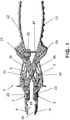
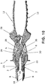
- the tool 1 of the present invention is a pliers-like clamp having a pair of combination prongs or jaws 2, 3 and corresponding handle members 12, 13 pivotally mounted with a hinge bolt 5 in relation with one another.
- the tool 1 is normally held in an open or ready to use position by the hinge bolt 5, which is preferably elastically biased by a spring 14 as shown in the more detailed view of Figure 4 .
- the spring 14 exerts its elastic biasing force in order to keep open the jaws 2 and 3 when the tool 1 in the ready to use position.
- the jaws 2, 3 have corresponding distal clamp portions 8 and 9 both having a relative flat clamping surface 18, 19 for gripping and holding the periphery of a patella bone (not shown in the figures).
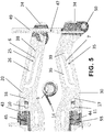
- the pliers-like tool 1 of the present invention include an intermediate force transmission system 4 or mechanism between the tool handles 12, 13, used by the surgeon, and the jaws 2, 3.
- This intermediate force transmission system 4 comprises a couple of arms 20 and 30 which are structurally independent from the handle members 12, 13 and are interposed between these handle members 12, 13 and the jaws 2, 3.
- each of the arms 20, 30 is substantially flat and has an arched shape with a distal end 22, 32 coupled to a corresponding jaw 2, 3 and a proximal end 24, 34 overlapping the handle members 12, 13 more proximally with reference to the hinge bolt 5.
- the two arms 20, 30 are substantially symmetrical in shave with the only exemption of the proximal end 24, 34 that is shaped differently for hosting different elements of the tool 1 that will be explained hereinafter.
- the jaws 2, 3 are mounted each in a removable manner on the corresponding distal end 22, 32 of the arms 20, 30 with interposition of an elastic element 45, 55 that will be disclosed hereinafter.
- a guide slot 16, 17 is provided on each arm 20, 30 for hosting a corresponding pin 10, 11 formed integrally with the corresponding jaw 2, 3 and extended in a direction perpendicular to the longitudinal extension of the jaws.
- Each pin 10, 11 is free to slide inside the guide slot 16, 17 to provide a slight axial movement of each jaw 2, 3 on the respective arm 20, 30.
- the distal clamp portions 8, 9 of the jaws 2, 3 are removable and are supported by a corresponding pin that is supported in a seat provided at the distal end of each arm 20, 30 and is partially visible in Figure 2 .
- a fastener mechanism 21, 23 is provided on each jaws to quick release the distal clamp portions 8, 9 for possible cleaning or substitution with other shaped clamps.
- Both the arms 20 and 30 include connecting means for coupling the orthopedic surgical pliers-like tool of the present invention with other associated and cooperating tools such as, for instance, a drill guide or a resection guide not shown in the drawings.
- the invention is not focused on the connecting means with such optional tools but it's important to remark that the arms are provided with those means.
- each of the arm 20, 30 includes an elastic portion 25, 35 for coupling each arm 20, 30 to the corresponding handle member 12, 13.
- Each elastic portion 25, 35 comprises an opening 26, 36 in each of the arms 20, 30 wherein an elastic element 6, 7 or tongue is protruding inside the opening.
- This tongue may be considered a sort of leaf spring having one end fixed to the arm structure and the other end free to move inside the respective opening 26 or 36.
- Each one of these elastic elements 6, 7 or tongue has one end formed integrally with the arm 20, 30 and an opposite enlarged free end 38, 39 that has a two-dimensional shape substantially similar to a drop.
- the enlarged free end 38 or 39 of the elastic element 6 or 7 is linked to a first point of the handle member 12 or 13 by a corresponding pin 27, 29.
- each handle member 12, 13 of the pliers-like tool 1 of the present invention is coupled to the intermediate force transmission system 4 in a couple of linking points.
- a first link point is the enlarged free end 38 or 39 of elastic element 6, 7 or tongue of one arm 20, 30.
- a second linking point is located in a slot 15, 31 formed in each of the arms 20, 30 which is engaged by a corresponding sliding pin 31, 33 fixed perpendicularly to the distal end 42, 46 of each handle member 12,13.
- the slots 15 and 31 are substantially parallel to the shorter slots 16 and 17 provided in a slightly staggered position on the corresponding arms 20, 30.
- the handle element 12 is cross linked to the enlarged free end 38 of the elastic element 6 of the arm 20 by the pin 27 located in an intermediate position of the handle member 12, more proximal than the hinge 5, and by the pin 33 located at the distal end 42 and sliding inside the slot 21 of the other arm 30.
- the handle element 13 is cross linked to the enlarged free end 39 of the elastic element 7 of the arm 30 by the pin 29 located in an intermediate position of the handle member 13, more proximal than the hinge 5, and by the pin 31 located at the distal end 46 and sliding inside the slot 15 of the other arm 20.
- one handle member 12 is linked to the arm 20 in a first link point 38 and to the other arm 30 in a second link point represented by the sliding coupling between the pin 33 and the slot 21.
- the other handle member 13 is linked to the second arm 30 in a first link point 39 and to the first arm 20 in a second link point represented by the sliding coupling between the pin 31 and the slot 15.
- the two handle members 12, 13 are coupled in the hinge bolt 5
- the above construction represent an intermediate force transmission system or mechanism that allows a first gentle exertion of gripping force when the surgeon acts of the handle members to grip and hold the patella bone through the distal approaching clamp portion 8 and 9.
- a second or further elastic gripping action may be exerted by the pliers-like tool 1 of the present invention according to the further features included in the tool 1 and disclosed hereinafter.
- a compression spring 45 or 55 is provided between each one of the arms 20 or 30 and the corresponding jaws 2, 3.
- the compression spring 45 or 55 is located in a corresponding seat 43, 44 formed between the arm 20, 30 and the corresponding jaws 2, 3 in the proximity of the slot 16 or 17.
- a locking means 47 is provided at the arms proximal ends 24, 34 to maintain a desired distance between the distal ends 8, 9 of the jaws or jaws 2,3.
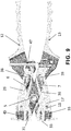
- An example of the locking means is a saw-toothed bar 49 that is pivotally mounted on a hinge 50 at the proximal 34 end of the arm 30, as shown in FIGS. 5-9 .
- the shape of the proximal end 34 of the second arm 30 is different from the shape of the other proximal end 24 of the first arm 20 just to host the hinge 50.
- a tooth or rachet 47 is provided on the proximal end 24 of the first arm 20 to engage step by step the teeth of the saw-toothed bar 49 when the arms 20, 30 are forced to approach one toward the other.
- a pushing button 28 is provided to release the rachet 47 from its engagement with the teeth of the saw-toothed bar 49 and release the handle members 12,1 3 to return the tool 1 in the ready to use position.
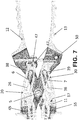
- the handle members 12, 13 can be closed freely by the surgeon until the distance between the flat surfaces 18, 19 of the jaws will reach a minimum clearance corresponding substantially to the patella bone thickness.
- the link between the handle members 12, 13 and the enlarged free ends 38, 39 of the elastic elements 6, 7 moves first of all these elastic elements before they reach a respective internal edge of the openings 26, 36.
- This first elastic reaction allows the tool to exert a gripping and holding force that is particularly gentle with respect to the patella bone.
- the handle members 12, 13 may be closed further applying a further pressure action that will meet the elastic reaction of the compression springs 45, 55 that will allow a further closing and gripping action still under elastic conditions.
- the tooth rack positioned at the end of the arms 20, 30 is stopping and keeping the desired distance. Pushing the button at the tooth rack will release the tooth and allows the arms / handles to open.
Landscapes
- Health & Medical Sciences (AREA)
- Life Sciences & Earth Sciences (AREA)
- Orthopedic Medicine & Surgery (AREA)
- Surgery (AREA)
- Animal Behavior & Ethology (AREA)
- General Health & Medical Sciences (AREA)
- Biomedical Technology (AREA)
- Heart & Thoracic Surgery (AREA)
- Veterinary Medicine (AREA)
- Engineering & Computer Science (AREA)
- Public Health (AREA)
- Molecular Biology (AREA)
- Nuclear Medicine, Radiotherapy & Molecular Imaging (AREA)
- Medical Informatics (AREA)
- Oral & Maxillofacial Surgery (AREA)
- Transplantation (AREA)
- Dentistry (AREA)
- Physical Education & Sports Medicine (AREA)
- Cardiology (AREA)
- Vascular Medicine (AREA)
- Surgical Instruments (AREA)
- Prostheses (AREA)
Claims (16)
- Orthopädisches chirurgisches Zangen-ähnliches Werkzeug (1) zum Durchführen einer Operation am Patella-Knochen, umfassend:- mindestens ein paar Backen (2, 3), die mit entsprechenden Griffelementen (12, 13) gekoppelt sind, die drehbar mit einem Gelenkbolzen (5) in Bezug zueinander gelagert sind;- einen distalen Klemmabschnitte (8, 9) an jeder Backe (2, 3) zum Greifen und Halten mindestens des Umfangs eines Patella-Knochens;- einen Zwischenkraftübertragungsmechanismus (4) zwischen den Werkzeuggriffelementen (12, 13) und den Backen (2, 3);- ein paar Arme (20, 30) in dem Zwischenkraftübertragungsmechanismus (4), die strukturell unabhängig von den Griffelementen (12, 13) sind und zwischen diesen Griffelementen (12, 13) und den Backen (2, 3) angeordnet sind;- einen elastischen Abschnitt (25, 35) in jedem Arm (20, 30) zum Koppeln jedes Arms mit einem entsprechenden Griffelement (12, 13) in einem ersten Verbindungspunkt (38, 39);- einen zweiten weiter distalen Verbindungspunkt (31, 33) in jedem Arm (20, 30), der mit einem entsprechenden distalen Ende (46, 42) eines Griffelements (12, 13) in Eingriff steht;- wobei der erste Verbindungspunkt (38, 39) eines Arms (20, 30) und der zweite Verbindungspunkt (31, 33) des anderen Arms mit dem gleichen Griffelement (12, 13) querverbunden sind, dadurch gekennzeichnet, dass jeder der Arme (20, 30) im Wesentlichen flach ist und eine gewölbte Form mit einem distalen Ende (22, 32) aufweist, das mit einer entsprechenden Backe (2, 3) gekoppelt ist, und ein proximales Ende (24, 34), das die Griffelemente (12, 13) näher in Bezug auf den Gelenkbolzen (5) überlappt.
- Zangen-ähnliches Werkzeug nach Anspruch 1, dadurch gekennzeichnet, dass die Arme (20, 30) so strukturiert sind, dass sie in einer unbelasteten Situation vorgeneigt sind und in der vollbelasteten Situation im Wesentlichen parallel zueinander gehalten werden, um die Lastübertragung auf den Patella-Knochen zu optimieren.
- Zangen-ähnliches Werkzeug nach Anspruch 1, dadurch gekennzeichnet, dass jeder der Arme (20, 30) einen elastischen Abschnitt (25, 35) zum Koppeln jedes Arms mit dem entsprechenden Griffelement (12, 13) aufweist und jeder elastische Abschnitt (25, 35) eine Öffnung (26, 36) in jedem der Arme (20, 30) aufweist, wobei ein elastisches Element (6, 7) oder eine Zunge innerhalb der Öffnung herausragt.
- Zangen-ähnliches Werkzeug nach Anspruch 1, dadurch gekennzeichnet, dass jeder der Arme (20, 30) einen elastischen Abschnitt (25, 35) zum Koppeln jedes Arms mit dem entsprechenden Griffelement (12, 13) aufweist und jeder elastische Abschnitt (25, 35) eine Öffnung (26, 36) in jedem der Arme (20, 30) aufweist, wobei eine Blattfeder vorgesehen ist, die ein Ende an der Armstruktur befestigt hat und das andere Ende (38, 39) frei beweglich innerhalb der jeweiligen Öffnung (26, 36) ist.
- Zangen-ähnliches Werkzeug nach Anspruch 3 oder 4, dadurch gekennzeichnet, dass das elastische Element (6, 7) oder die Blattfeder ein vergrößertes freies Ende (38, 39) aufweist, das mit einem ersten Verbindungspunkt des Griffelements (12, 13) durch einen entsprechenden Stift (27, 29) verbunden ist.
- Zangen-ähnliches Werkzeug nach Anspruch 1, dadurch gekennzeichnet, dass der zweite weiter distale Verbindungspunkt (31, 33) in einem Schlitz (15, 21) angeordnet ist, der in jedem der Arme (20, 30) ausgebildet ist und in den von einem entsprechenden Gleitstift (31, 33) eingegriffen wird, der rechtwinklig zu dem distalen Ende (42, 46) jedes Griffelements (12, 13) befestigt ist.
- Zangen-ähnliches Werkzeug nach Anspruch 5, dadurch gekennzeichnet, dass jedes Griffelement (12, 13) mit dem vergrößerten freien Ende (38, 39) des elastischen Elements (6, 7) eines Arms (20, 30) durch einen Stift (27, 29), der in einer Zwischenposition des Griffelements (12, 13) angeordnet ist, und mit dem anderen Arm (30, 20) durch einen Gleitstift (33) querverbunden ist, der an dem distalen Ende (42, 46) des Griffelements (12, 13) angeordnet ist und in einem Schlitz (15, 21) des anderen Arms (30, 20) gleitet.
- Zangen-ähnliches Werkzeug nach Anspruch 7, dadurch gekennzeichnet, dass der Gleitstift (31, 33) rechtwinklig zu dem distalen Ende (42, 46) jedes Griffelements (12, 13) befestigt ist.
- Zangen-ähnliches Werkzeug nach Anspruch 1, dadurch gekennzeichnet, dass die Backen (2, 3) abnehmbar an dem entsprechenden distalen Ende (22, 32) der Arme (20, 30) unter Zwischenschaltung eines elastischen Elements (45, 55) montiert sind.
- Zangen-ähnliches Werkzeug nach Anspruch 9, dadurch gekennzeichnet, dass an dem distalen Ende (22, 32) jedes Arms (20, 30) ein Führungsschlitz (16, 17) zur Aufnahme eines entsprechenden Stiftes (10, 11) vorgesehen ist, der integral mit der entsprechenden Backe (2, 3) ausgebildet und in einer Richtung rechtwinklig zu der Längserstreckung der Backen verlängert ist.
- Zangen-ähnliches Werkzeug nach Anspruch 10, dadurch gekennzeichnet, dass jeder der Stifte (10, 11) frei in dem entsprechenden Führungsschlitz (16, 17) gleiten kann, um eine leichte axiale Bewegung jeder Backe (2, 3) an dem jeweiligen Arm (20, 30) im Gegensatz zu dem elastischen Element (45, 55) zu bewirken.
- Zangen-ähnliches Werkzeug nach Anspruch 1, dadurch gekennzeichnet, dass an den proximalen Enden (24, 34) der Arme (20, 30) ein Verriegelungsmittel (47) vorgesehen ist, um einen gewünschten Abstand zwischen den distalen Klemmabschnitten (8, 9) der Backen oder Backen (2, 3) einzuhalten.
- Zangen-ähnliches Werkzeug nach Anspruch 12, dadurch gekennzeichnet, dass das Verriegelungsmittel (47) eine gezahnte Stange (49) umfasst, die drehbar an einem Scharnier (50) an dem proximalen (34) Ende eines Arms (30) montiert ist und von einer an dem proximalen Ende (24) des anderen Arms (20) vorgesehenen Ratsche (47) in Eingriff genommen wird, wenn die Arme (20, 30) durch die Griffelemente (12, 13) gezwungen sind, sich einander anzunähern.
- Zangen-ähnliches Werkzeug nach Anspruch 13, dadurch gekennzeichnet, dass an dem proximalen Ende (24) eines Arms (20) ein Druckknopf (28) vorgesehen ist, um die Ratsche (47) von ihrem Eingriff mit den Zähnen der gezahnte Stange (49) zu lösen und die Griffelemente 12, 13 zum Zurückführen des Werkzeugs (1) in die gebrauchsbereite Position zu lösen.
- Zangen-ähnliches Werkzeug nach Anspruch 1, dadurch gekennzeichnet, dass zwischen jedem der Arme (20, 30) und den entsprechenden Backen (2, 3) eine Druckfeder (45, 55) vorgesehen ist.
- Zangen-ähnliches Werkzeug nach Anspruch 1, dadurch gekennzeichnet, dass die distalen Klemmabschnitte (8, 9) der Backen (2, 3) abnehmbar sind und von einem entsprechenden Stift getragen werden, der in einem an dem distalen Ende jedes der Arme (20, 30) vorgesehenen Sitz getragen wird; ein Befestigungsmechanismus (21, 23) an jeder Backe (2, 3) vorgesehen ist, um die distalen Klemmabschnitte (8, 9) schnell zu lösen.
Priority Applications (6)
| Application Number | Priority Date | Filing Date | Title |
|---|---|---|---|
| EP16179380.7A EP3269320B1 (de) | 2016-07-14 | 2016-07-14 | Orthopädisches chirurgisches zangenartiges schneidwerkzeug zum halten und greifen eines patellaknochens |
| ES16179380T ES2778842T3 (es) | 2016-07-14 | 2016-07-14 | Herramienta quirúrgica ortopédica de tipo alicate para sostener y agarrar un hueso de rótula |
| AU2017204618A AU2017204618B2 (en) | 2016-07-14 | 2017-07-06 | Orthopedic surgical pliers-like tool for holding and gripping a patella bone |
| US15/647,897 US10398456B2 (en) | 2016-07-14 | 2017-07-12 | Orthopedic surgical pliers-like tool for holding and gripping a patella bone |
| BR102017015046-1A BR102017015046B1 (pt) | 2016-07-14 | 2017-07-13 | Ferramenta cirúrgica ortopédica |
| JP2017137571A JP6989222B2 (ja) | 2016-07-14 | 2017-07-14 | 膝蓋骨を保持し及びつかむための整形外科手術用プライヤ状器具 |
Applications Claiming Priority (1)
| Application Number | Priority Date | Filing Date | Title |
|---|---|---|---|
| EP16179380.7A EP3269320B1 (de) | 2016-07-14 | 2016-07-14 | Orthopädisches chirurgisches zangenartiges schneidwerkzeug zum halten und greifen eines patellaknochens |
Publications (2)
| Publication Number | Publication Date |
|---|---|
| EP3269320A1 EP3269320A1 (de) | 2018-01-17 |
| EP3269320B1 true EP3269320B1 (de) | 2019-12-18 |
Family
ID=56411507
Family Applications (1)
| Application Number | Title | Priority Date | Filing Date |
|---|---|---|---|
| EP16179380.7A Active EP3269320B1 (de) | 2016-07-14 | 2016-07-14 | Orthopädisches chirurgisches zangenartiges schneidwerkzeug zum halten und greifen eines patellaknochens |
Country Status (6)
| Country | Link |
|---|---|
| US (1) | US10398456B2 (de) |
| EP (1) | EP3269320B1 (de) |
| JP (1) | JP6989222B2 (de) |
| AU (1) | AU2017204618B2 (de) |
| BR (1) | BR102017015046B1 (de) |
| ES (1) | ES2778842T3 (de) |
Families Citing this family (10)
| Publication number | Priority date | Publication date | Assignee | Title |
|---|---|---|---|---|
| US10390814B2 (en) | 2016-04-20 | 2019-08-27 | Medos International Sarl | Meniscal repair devices, systems, and methods |
| CN108784822B (zh) * | 2018-03-08 | 2021-03-30 | 吉林大学 | 一种用于脊柱取出骨内螺钉的夹钳装置 |
| CN108577912A (zh) * | 2018-05-24 | 2018-09-28 | 杭州市妇产科医院 | 一种医用持针钳 |
| CN109646155B (zh) * | 2019-02-15 | 2023-11-21 | 天衍医疗器材有限公司 | 一种便于假体植入的多用式持髁器 |
| CN110772298B (zh) * | 2019-08-30 | 2025-11-21 | 宽岳医疗器材(苏州)有限公司 | 髌骨切除钳 |
| KR200492962Y1 (ko) * | 2019-12-27 | 2021-01-12 | 주식회사 한국가스기술공사 | 휴대식 오링 접합장치 |
| USD991451S1 (en) * | 2020-10-27 | 2023-07-04 | Depuy Ireland Unlimited Company | Patella clamp |
| KR102532026B1 (ko) * | 2020-11-13 | 2023-05-15 | 경북대학교 산학협력단 | 무릎 인공관절 전치환술 시 사용되는 슬개골(Patella) 고정기구 및 이의 제조방법 |
| US12458375B2 (en) * | 2022-03-29 | 2025-11-04 | Howmedica Osteonics Corp. | Proximal hip drill clamp with implant |
| EP4534048B1 (de) * | 2023-10-05 | 2026-01-28 | Aesculap AG | Patellaimpaktionsvorrichtung und patellavorbereitungsset |
Family Cites Families (14)
| Publication number | Priority date | Publication date | Assignee | Title |
|---|---|---|---|---|
| JPS62201662U (de) * | 1986-06-13 | 1987-12-22 | ||
| DE3809793A1 (de) * | 1988-03-23 | 1989-10-05 | Link Waldemar Gmbh Co | Chirurgischer instrumentensatz |
| US5147365A (en) | 1991-08-19 | 1992-09-15 | Intermedics Orthopedics, Inc. | Patellar osteotomy guide |
| US5536271A (en) * | 1994-06-02 | 1996-07-16 | Depuy, Inc. | Patella reaming system |
| US5968051A (en) * | 1995-07-27 | 1999-10-19 | Johnson & Johnson Professional, Inc. | Patella clamping device |
| US5944723A (en) * | 1998-03-27 | 1999-08-31 | Johnson & Johnson Professional, Inc. | Locking orthopaedic clamping tool |
| US6010509A (en) | 1998-07-01 | 2000-01-04 | The Dana Center For Orthopaedic Implants | Patella resection drill and prosthesis implantation device |
| US7632279B2 (en) * | 2004-12-27 | 2009-12-15 | Howmedica Osteonics Corp. | Patella resection clamp |
| US7758651B2 (en) * | 2006-10-18 | 2010-07-20 | Howmedica Osteonics Corp. | Mis patellar preparation |
| USD667552S1 (en) * | 2010-06-01 | 2012-09-18 | Zimmer, Inc. | Patella clamp |
| US8728087B2 (en) * | 2010-10-13 | 2014-05-20 | Howmedica Osteonics Corp. | Automatically adjusting patella cutting guide |
| US9364245B2 (en) * | 2012-06-15 | 2016-06-14 | Microport Orthopedics Holdings Inc. | Patellar clamping instrument |
| US10085758B2 (en) * | 2012-09-28 | 2018-10-02 | Depuy Ireland Unlimited Company | Patella drill guide and trial surgical instrument having an alignment bore formed therein and method of using the same |
| EP3072462B1 (de) * | 2015-03-27 | 2017-10-04 | DePuy Ireland Unlimited Company | Orthopädisches, chirurgisches instrumentensystem |
-
2016
- 2016-07-14 EP EP16179380.7A patent/EP3269320B1/de active Active
- 2016-07-14 ES ES16179380T patent/ES2778842T3/es active Active
-
2017
- 2017-07-06 AU AU2017204618A patent/AU2017204618B2/en active Active
- 2017-07-12 US US15/647,897 patent/US10398456B2/en active Active
- 2017-07-13 BR BR102017015046-1A patent/BR102017015046B1/pt active IP Right Grant
- 2017-07-14 JP JP2017137571A patent/JP6989222B2/ja active Active
Non-Patent Citations (1)
| Title |
|---|
| None * |
Also Published As
| Publication number | Publication date |
|---|---|
| US20180014839A1 (en) | 2018-01-18 |
| JP2018038801A (ja) | 2018-03-15 |
| EP3269320A1 (de) | 2018-01-17 |
| AU2017204618A1 (en) | 2018-02-01 |
| BR102017015046A2 (pt) | 2018-02-06 |
| ES2778842T3 (es) | 2020-08-12 |
| JP6989222B2 (ja) | 2022-01-05 |
| US10398456B2 (en) | 2019-09-03 |
| BR102017015046B1 (pt) | 2022-12-13 |
| AU2017204618B2 (en) | 2022-05-12 |
Similar Documents
| Publication | Publication Date | Title |
|---|---|---|
| EP3269320B1 (de) | Orthopädisches chirurgisches zangenartiges schneidwerkzeug zum halten und greifen eines patellaknochens | |
| EP2556801B1 (de) | Patellaresektionsanordnung | |
| US5122150A (en) | Neurosurgical clip applier | |
| US9486212B2 (en) | Bone staple storage, inserter, and method for use therewith | |
| US7806899B2 (en) | Patellar resection tool | |
| US20120095473A1 (en) | Automatically adjusting patella cutting guide | |
| US20140207123A1 (en) | Knockout Tool for Minimally Invasive Prosthesis Revision | |
| US9724117B2 (en) | Medical, in particular surgical, sliding-shaft instrument | |
| JP2000139935A (ja) | 整形外科用鉗子器具システムおよび鉗子器具 | |
| US9333022B2 (en) | Tool for extracting a pin | |
| US10932795B2 (en) | Cutting guide and method | |
| US9750554B2 (en) | Instrument for extracting a pin | |
| US8449548B2 (en) | Broach handle with flexure spring | |
| EP2837364B1 (de) | Chirurgischer Impinger/Extraktor und Verwendungsverfahren | |
| EP2574291B1 (de) | Patellaresektionsanordnung | |
| US20230346411A1 (en) | Surgical instruments with compliant mechanism design | |
| EP3107467B1 (de) | Chirurgisches instrument |
Legal Events
| Date | Code | Title | Description |
|---|---|---|---|
| PUAI | Public reference made under article 153(3) epc to a published international application that has entered the european phase |
Free format text: ORIGINAL CODE: 0009012 |
|
| STAA | Information on the status of an ep patent application or granted ep patent |
Free format text: STATUS: THE APPLICATION HAS BEEN PUBLISHED |
|
| AK | Designated contracting states |
Kind code of ref document: A1 Designated state(s): AL AT BE BG CH CY CZ DE DK EE ES FI FR GB GR HR HU IE IS IT LI LT LU LV MC MK MT NL NO PL PT RO RS SE SI SK SM TR |
|
| AX | Request for extension of the european patent |
Extension state: BA ME |
|
| STAA | Information on the status of an ep patent application or granted ep patent |
Free format text: STATUS: REQUEST FOR EXAMINATION WAS MADE |
|
| 17P | Request for examination filed |
Effective date: 20180717 |
|
| RBV | Designated contracting states (corrected) |
Designated state(s): AL AT BE BG CH CY CZ DE DK EE ES FI FR GB GR HR HU IE IS IT LI LT LU LV MC MK MT NL NO PL PT RO RS SE SI SK SM TR |
|
| GRAP | Despatch of communication of intention to grant a patent |
Free format text: ORIGINAL CODE: EPIDOSNIGR1 |
|
| STAA | Information on the status of an ep patent application or granted ep patent |
Free format text: STATUS: GRANT OF PATENT IS INTENDED |
|
| RIC1 | Information provided on ipc code assigned before grant |
Ipc: A61B 17/88 20060101AFI20190513BHEP |
|
| INTG | Intention to grant announced |
Effective date: 20190603 |
|
| GRAS | Grant fee paid |
Free format text: ORIGINAL CODE: EPIDOSNIGR3 |
|
| GRAJ | Information related to disapproval of communication of intention to grant by the applicant or resumption of examination proceedings by the epo deleted |
Free format text: ORIGINAL CODE: EPIDOSDIGR1 |
|
| GRAL | Information related to payment of fee for publishing/printing deleted |
Free format text: ORIGINAL CODE: EPIDOSDIGR3 |
|
| STAA | Information on the status of an ep patent application or granted ep patent |
Free format text: STATUS: REQUEST FOR EXAMINATION WAS MADE |
|
| GRAP | Despatch of communication of intention to grant a patent |
Free format text: ORIGINAL CODE: EPIDOSNIGR1 |
|
| STAA | Information on the status of an ep patent application or granted ep patent |
Free format text: STATUS: GRANT OF PATENT IS INTENDED |
|
| INTC | Intention to grant announced (deleted) | ||
| GRAA | (expected) grant |
Free format text: ORIGINAL CODE: 0009210 |
|
| STAA | Information on the status of an ep patent application or granted ep patent |
Free format text: STATUS: THE PATENT HAS BEEN GRANTED |
|
| INTG | Intention to grant announced |
Effective date: 20191024 |
|
| AK | Designated contracting states |
Kind code of ref document: B1 Designated state(s): AL AT BE BG CH CY CZ DE DK EE ES FI FR GB GR HR HU IE IS IT LI LT LU LV MC MK MT NL NO PL PT RO RS SE SI SK SM TR |
|
| REG | Reference to a national code |
Ref country code: CH Ref legal event code: EP |
|
| REG | Reference to a national code |
Ref country code: IE Ref legal event code: FG4D |
|
| REG | Reference to a national code |
Ref country code: DE Ref legal event code: R096 Ref document number: 602016026274 Country of ref document: DE |
|
| REG | Reference to a national code |
Ref country code: AT Ref legal event code: REF Ref document number: 1213718 Country of ref document: AT Kind code of ref document: T Effective date: 20200115 |
|
| REG | Reference to a national code |
Ref country code: CH Ref legal event code: NV Representative=s name: ING. MARCO ZARDI C/O M. ZARDI AND CO. S.A., CH |
|
| REG | Reference to a national code |
Ref country code: NL Ref legal event code: MP Effective date: 20191218 |
|
| PG25 | Lapsed in a contracting state [announced via postgrant information from national office to epo] |
Ref country code: FI Free format text: LAPSE BECAUSE OF FAILURE TO SUBMIT A TRANSLATION OF THE DESCRIPTION OR TO PAY THE FEE WITHIN THE PRESCRIBED TIME-LIMIT Effective date: 20191218 Ref country code: BG Free format text: LAPSE BECAUSE OF FAILURE TO SUBMIT A TRANSLATION OF THE DESCRIPTION OR TO PAY THE FEE WITHIN THE PRESCRIBED TIME-LIMIT Effective date: 20200318 Ref country code: SE Free format text: LAPSE BECAUSE OF FAILURE TO SUBMIT A TRANSLATION OF THE DESCRIPTION OR TO PAY THE FEE WITHIN THE PRESCRIBED TIME-LIMIT Effective date: 20191218 Ref country code: LV Free format text: LAPSE BECAUSE OF FAILURE TO SUBMIT A TRANSLATION OF THE DESCRIPTION OR TO PAY THE FEE WITHIN THE PRESCRIBED TIME-LIMIT Effective date: 20191218 Ref country code: NO Free format text: LAPSE BECAUSE OF FAILURE TO SUBMIT A TRANSLATION OF THE DESCRIPTION OR TO PAY THE FEE WITHIN THE PRESCRIBED TIME-LIMIT Effective date: 20200318 Ref country code: LT Free format text: LAPSE BECAUSE OF FAILURE TO SUBMIT A TRANSLATION OF THE DESCRIPTION OR TO PAY THE FEE WITHIN THE PRESCRIBED TIME-LIMIT Effective date: 20191218 Ref country code: GR Free format text: LAPSE BECAUSE OF FAILURE TO SUBMIT A TRANSLATION OF THE DESCRIPTION OR TO PAY THE FEE WITHIN THE PRESCRIBED TIME-LIMIT Effective date: 20200319 |
|
| REG | Reference to a national code |
Ref country code: LT Ref legal event code: MG4D |
|
| PG25 | Lapsed in a contracting state [announced via postgrant information from national office to epo] |
Ref country code: HR Free format text: LAPSE BECAUSE OF FAILURE TO SUBMIT A TRANSLATION OF THE DESCRIPTION OR TO PAY THE FEE WITHIN THE PRESCRIBED TIME-LIMIT Effective date: 20191218 Ref country code: RS Free format text: LAPSE BECAUSE OF FAILURE TO SUBMIT A TRANSLATION OF THE DESCRIPTION OR TO PAY THE FEE WITHIN THE PRESCRIBED TIME-LIMIT Effective date: 20191218 |
|
| PG25 | Lapsed in a contracting state [announced via postgrant information from national office to epo] |
Ref country code: AL Free format text: LAPSE BECAUSE OF FAILURE TO SUBMIT A TRANSLATION OF THE DESCRIPTION OR TO PAY THE FEE WITHIN THE PRESCRIBED TIME-LIMIT Effective date: 20191218 |
|
| PG25 | Lapsed in a contracting state [announced via postgrant information from national office to epo] |
Ref country code: EE Free format text: LAPSE BECAUSE OF FAILURE TO SUBMIT A TRANSLATION OF THE DESCRIPTION OR TO PAY THE FEE WITHIN THE PRESCRIBED TIME-LIMIT Effective date: 20191218 Ref country code: NL Free format text: LAPSE BECAUSE OF FAILURE TO SUBMIT A TRANSLATION OF THE DESCRIPTION OR TO PAY THE FEE WITHIN THE PRESCRIBED TIME-LIMIT Effective date: 20191218 Ref country code: RO Free format text: LAPSE BECAUSE OF FAILURE TO SUBMIT A TRANSLATION OF THE DESCRIPTION OR TO PAY THE FEE WITHIN THE PRESCRIBED TIME-LIMIT Effective date: 20191218 Ref country code: PT Free format text: LAPSE BECAUSE OF FAILURE TO SUBMIT A TRANSLATION OF THE DESCRIPTION OR TO PAY THE FEE WITHIN THE PRESCRIBED TIME-LIMIT Effective date: 20200513 Ref country code: CZ Free format text: LAPSE BECAUSE OF FAILURE TO SUBMIT A TRANSLATION OF THE DESCRIPTION OR TO PAY THE FEE WITHIN THE PRESCRIBED TIME-LIMIT Effective date: 20191218 |
|
| REG | Reference to a national code |
Ref country code: ES Ref legal event code: FG2A Ref document number: 2778842 Country of ref document: ES Kind code of ref document: T3 Effective date: 20200812 |
|
| PG25 | Lapsed in a contracting state [announced via postgrant information from national office to epo] |
Ref country code: SM Free format text: LAPSE BECAUSE OF FAILURE TO SUBMIT A TRANSLATION OF THE DESCRIPTION OR TO PAY THE FEE WITHIN THE PRESCRIBED TIME-LIMIT Effective date: 20191218 Ref country code: SK Free format text: LAPSE BECAUSE OF FAILURE TO SUBMIT A TRANSLATION OF THE DESCRIPTION OR TO PAY THE FEE WITHIN THE PRESCRIBED TIME-LIMIT Effective date: 20191218 Ref country code: IS Free format text: LAPSE BECAUSE OF FAILURE TO SUBMIT A TRANSLATION OF THE DESCRIPTION OR TO PAY THE FEE WITHIN THE PRESCRIBED TIME-LIMIT Effective date: 20200418 |
|
| REG | Reference to a national code |
Ref country code: DE Ref legal event code: R097 Ref document number: 602016026274 Country of ref document: DE |
|
| REG | Reference to a national code |
Ref country code: AT Ref legal event code: MK05 Ref document number: 1213718 Country of ref document: AT Kind code of ref document: T Effective date: 20191218 |
|
| PLBE | No opposition filed within time limit |
Free format text: ORIGINAL CODE: 0009261 |
|
| STAA | Information on the status of an ep patent application or granted ep patent |
Free format text: STATUS: NO OPPOSITION FILED WITHIN TIME LIMIT |
|
| PG25 | Lapsed in a contracting state [announced via postgrant information from national office to epo] |
Ref country code: DK Free format text: LAPSE BECAUSE OF FAILURE TO SUBMIT A TRANSLATION OF THE DESCRIPTION OR TO PAY THE FEE WITHIN THE PRESCRIBED TIME-LIMIT Effective date: 20191218 |
|
| 26N | No opposition filed |
Effective date: 20200921 |
|
| PG25 | Lapsed in a contracting state [announced via postgrant information from national office to epo] |
Ref country code: AT Free format text: LAPSE BECAUSE OF FAILURE TO SUBMIT A TRANSLATION OF THE DESCRIPTION OR TO PAY THE FEE WITHIN THE PRESCRIBED TIME-LIMIT Effective date: 20191218 Ref country code: SI Free format text: LAPSE BECAUSE OF FAILURE TO SUBMIT A TRANSLATION OF THE DESCRIPTION OR TO PAY THE FEE WITHIN THE PRESCRIBED TIME-LIMIT Effective date: 20191218 |
|
| PG25 | Lapsed in a contracting state [announced via postgrant information from national office to epo] |
Ref country code: MC Free format text: LAPSE BECAUSE OF FAILURE TO SUBMIT A TRANSLATION OF THE DESCRIPTION OR TO PAY THE FEE WITHIN THE PRESCRIBED TIME-LIMIT Effective date: 20191218 Ref country code: PL Free format text: LAPSE BECAUSE OF FAILURE TO SUBMIT A TRANSLATION OF THE DESCRIPTION OR TO PAY THE FEE WITHIN THE PRESCRIBED TIME-LIMIT Effective date: 20191218 |
|
| PG25 | Lapsed in a contracting state [announced via postgrant information from national office to epo] |
Ref country code: LU Free format text: LAPSE BECAUSE OF NON-PAYMENT OF DUE FEES Effective date: 20200714 |
|
| PG25 | Lapsed in a contracting state [announced via postgrant information from national office to epo] |
Ref country code: TR Free format text: LAPSE BECAUSE OF FAILURE TO SUBMIT A TRANSLATION OF THE DESCRIPTION OR TO PAY THE FEE WITHIN THE PRESCRIBED TIME-LIMIT Effective date: 20191218 Ref country code: MT Free format text: LAPSE BECAUSE OF FAILURE TO SUBMIT A TRANSLATION OF THE DESCRIPTION OR TO PAY THE FEE WITHIN THE PRESCRIBED TIME-LIMIT Effective date: 20191218 Ref country code: CY Free format text: LAPSE BECAUSE OF FAILURE TO SUBMIT A TRANSLATION OF THE DESCRIPTION OR TO PAY THE FEE WITHIN THE PRESCRIBED TIME-LIMIT Effective date: 20191218 |
|
| PG25 | Lapsed in a contracting state [announced via postgrant information from national office to epo] |
Ref country code: MK Free format text: LAPSE BECAUSE OF FAILURE TO SUBMIT A TRANSLATION OF THE DESCRIPTION OR TO PAY THE FEE WITHIN THE PRESCRIBED TIME-LIMIT Effective date: 20191218 |
|
| P01 | Opt-out of the competence of the unified patent court (upc) registered |
Effective date: 20230520 |
|
| PGFP | Annual fee paid to national office [announced via postgrant information from national office to epo] |
Ref country code: GB Payment date: 20250619 Year of fee payment: 10 |
|
| PGFP | Annual fee paid to national office [announced via postgrant information from national office to epo] |
Ref country code: BE Payment date: 20250619 Year of fee payment: 10 |
|
| PGFP | Annual fee paid to national office [announced via postgrant information from national office to epo] |
Ref country code: FR Payment date: 20250620 Year of fee payment: 10 |
|
| PGFP | Annual fee paid to national office [announced via postgrant information from national office to epo] |
Ref country code: IE Payment date: 20250623 Year of fee payment: 10 |
|
| PGFP | Annual fee paid to national office [announced via postgrant information from national office to epo] |
Ref country code: ES Payment date: 20250801 Year of fee payment: 10 |
|
| PGFP | Annual fee paid to national office [announced via postgrant information from national office to epo] |
Ref country code: DE Payment date: 20250620 Year of fee payment: 10 |
|
| PGFP | Annual fee paid to national office [announced via postgrant information from national office to epo] |
Ref country code: IT Payment date: 20250723 Year of fee payment: 10 |
|
| PGFP | Annual fee paid to national office [announced via postgrant information from national office to epo] |
Ref country code: CH Payment date: 20250801 Year of fee payment: 10 |