EP3269162B1 - Methods for backhaul operations in millimeter wave networks - Google Patents
Methods for backhaul operations in millimeter wave networks Download PDFInfo
- Publication number
- EP3269162B1 EP3269162B1 EP16707350.1A EP16707350A EP3269162B1 EP 3269162 B1 EP3269162 B1 EP 3269162B1 EP 16707350 A EP16707350 A EP 16707350A EP 3269162 B1 EP3269162 B1 EP 3269162B1
- Authority
- EP
- European Patent Office
- Prior art keywords
- base station
- mmw
- wireless communication
- millimeter wave
- timing
- Prior art date
- Legal status (The legal status is an assumption and is not a legal conclusion. Google has not performed a legal analysis and makes no representation as to the accuracy of the status listed.)
- Active
Links
- 238000000034 method Methods 0.000 title claims description 158
- 238000004891 communication Methods 0.000 claims description 238
- 230000006854 communication Effects 0.000 claims description 238
- 238000012544 monitoring process Methods 0.000 claims description 6
- 238000012545 processing Methods 0.000 claims description 3
- 238000004590 computer program Methods 0.000 claims description 2
- 238000010586 diagram Methods 0.000 description 32
- 230000005540 biological transmission Effects 0.000 description 31
- 230000006870 function Effects 0.000 description 31
- 238000005516 engineering process Methods 0.000 description 10
- 230000008054 signal transmission Effects 0.000 description 9
- 238000001228 spectrum Methods 0.000 description 6
- 230000008901 benefit Effects 0.000 description 5
- 239000000969 carrier Substances 0.000 description 5
- 238000005259 measurement Methods 0.000 description 5
- 230000002776 aggregation Effects 0.000 description 3
- 238000004220 aggregation Methods 0.000 description 3
- 230000010267 cellular communication Effects 0.000 description 3
- 239000000835 fiber Substances 0.000 description 3
- 230000003287 optical effect Effects 0.000 description 3
- 230000008520 organization Effects 0.000 description 3
- 230000004044 response Effects 0.000 description 3
- 230000001360 synchronised effect Effects 0.000 description 3
- 230000001413 cellular effect Effects 0.000 description 2
- 238000001514 detection method Methods 0.000 description 2
- 230000000977 initiatory effect Effects 0.000 description 2
- 239000002245 particle Substances 0.000 description 2
- 230000008569 process Effects 0.000 description 2
- 238000000638 solvent extraction Methods 0.000 description 2
- 238000013459 approach Methods 0.000 description 1
- 238000003491 array Methods 0.000 description 1
- 238000013475 authorization Methods 0.000 description 1
- 230000009286 beneficial effect Effects 0.000 description 1
- 230000007175 bidirectional communication Effects 0.000 description 1
- 239000003795 chemical substances by application Substances 0.000 description 1
- 238000013461 design Methods 0.000 description 1
- 238000011161 development Methods 0.000 description 1
- 230000018109 developmental process Effects 0.000 description 1
- 230000007613 environmental effect Effects 0.000 description 1
- 230000007774 longterm Effects 0.000 description 1
- 238000012423 maintenance Methods 0.000 description 1
- 238000010295 mobile communication Methods 0.000 description 1
- 238000012986 modification Methods 0.000 description 1
- 230000004048 modification Effects 0.000 description 1
- 230000002441 reversible effect Effects 0.000 description 1
- 230000011218 segmentation Effects 0.000 description 1
- 238000012163 sequencing technique Methods 0.000 description 1
- 238000010408 sweeping Methods 0.000 description 1
- 238000012546 transfer Methods 0.000 description 1
Images


Classifications
-
- H—ELECTRICITY
- H04—ELECTRIC COMMUNICATION TECHNIQUE
- H04W—WIRELESS COMMUNICATION NETWORKS
- H04W8/00—Network data management
-
- H—ELECTRICITY
- H04—ELECTRIC COMMUNICATION TECHNIQUE
- H04W—WIRELESS COMMUNICATION NETWORKS
- H04W8/00—Network data management
- H04W8/005—Discovery of network devices, e.g. terminals
-
- H—ELECTRICITY
- H04—ELECTRIC COMMUNICATION TECHNIQUE
- H04W—WIRELESS COMMUNICATION NETWORKS
- H04W48/00—Access restriction; Network selection; Access point selection
- H04W48/16—Discovering, processing access restriction or access information
-
- H—ELECTRICITY
- H04—ELECTRIC COMMUNICATION TECHNIQUE
- H04B—TRANSMISSION
- H04B7/00—Radio transmission systems, i.e. using radiation field
- H04B7/14—Relay systems
- H04B7/15—Active relay systems
- H04B7/155—Ground-based stations
- H04B7/15507—Relay station based processing for cell extension or control of coverage area
-
- H—ELECTRICITY
- H04—ELECTRIC COMMUNICATION TECHNIQUE
- H04L—TRANSMISSION OF DIGITAL INFORMATION, e.g. TELEGRAPHIC COMMUNICATION
- H04L12/00—Data switching networks
- H04L12/28—Data switching networks characterised by path configuration, e.g. LAN [Local Area Networks] or WAN [Wide Area Networks]
- H04L12/46—Interconnection of networks
-
- H—ELECTRICITY
- H04—ELECTRIC COMMUNICATION TECHNIQUE
- H04W—WIRELESS COMMUNICATION NETWORKS
- H04W56/00—Synchronisation arrangements
- H04W56/001—Synchronization between nodes
-
- H—ELECTRICITY
- H04—ELECTRIC COMMUNICATION TECHNIQUE
- H04W—WIRELESS COMMUNICATION NETWORKS
- H04W84/00—Network topologies
- H04W84/18—Self-organising networks, e.g. ad-hoc networks or sensor networks
- H04W84/22—Self-organising networks, e.g. ad-hoc networks or sensor networks with access to wired networks
-
- H—ELECTRICITY
- H04—ELECTRIC COMMUNICATION TECHNIQUE
- H04W—WIRELESS COMMUNICATION NETWORKS
- H04W88/00—Devices specially adapted for wireless communication networks, e.g. terminals, base stations or access point devices
- H04W88/08—Access point devices
-
- H—ELECTRICITY
- H04—ELECTRIC COMMUNICATION TECHNIQUE
- H04W—WIRELESS COMMUNICATION NETWORKS
- H04W88/00—Devices specially adapted for wireless communication networks, e.g. terminals, base stations or access point devices
- H04W88/02—Terminal devices
- H04W88/04—Terminal devices adapted for relaying to or from another terminal or user
Definitions
- the present disclosure for example, relates to wireless communication systems, and more particularly to backhaul operations in a millimeter wave wireless communication system.
- Wireless communication systems are widely deployed to provide various types of communication content such as voice, video, packet data, messaging, broadcast, and so on. These systems may be multiple-access systems capable of supporting communication with multiple users by sharing the available system resources (e.g ., time, frequency, and power). Examples of such multiple-access systems include code-division multiple access (CDMA) systems, time-division multiple access (TDMA) systems, frequency-division multiple access (FDMA) systems, and orthogonal frequency-division multiple access (OFDMA) systems.
- CDMA code-division multiple access
- TDMA time-division multiple access
- FDMA frequency-division multiple access
- OFDMA orthogonal frequency-division multiple access
- a wireless multiple-access communication system may include a number of base stations, each simultaneously supporting communication for multiple communication devices, otherwise known as user equipments (UEs).
- a base station may communicate with UEs on downlink channels (e.g., for transmissions from a base station to a UE) and uplink channels (e.g., for transmissions from a UE to a base station).
- a base station may communicate, either directly or indirectly with other base stations over backhaul links.
- a base station in a conventional communication system, typically enjoys a robust link to a network entity which coordinates aspects of the discovery and backhaul communications, e.g., the network entity provides timing information, cell identity, etc., for neighboring base stations to coordinate discovery and backhaul transmissions.
- Base stations operating in the millimeter wave (mmW) frequency ranges e.g ., 28 GHz, 40 GHz, 60 GHz, etc., may be associated with a reduced coverage area (e.g., a smaller geographic footprint, directional transmissions only, etc. ), which may result in deployment of a much larger number of base stations to provide acceptable coverage areas.
- mmW millimeter wave
- Such large-scale mmW base station deployments may impact the quality and availability of links to a network entity.
- some mmW base stations may be deployed in areas with limited bandwidth links to a network entity and, in some examples, no links to a network entity.
- base stations may rely on a wired connection to a network entity and, therefore, may not typically perform discovery over the wireless medium.
- Such mmW base stations with limited or no links to a network entity still have a need to be able to discover other mmW base stations in order to perform backhaul operations.
- wireless discovery operations may provide a more beneficial deployment scheme for a dense population of mmW base stations, e.g ., provide a lower cost and more feasible option to installing fiber optic communication lines to each mmW base station.
- Document WO 2014/036059 A1 relates to methods for implement granting a license to a millimeter wave base station (mB) in a wireless network.
- the mB may send a license request.
- the license request may be associated with a beam direction in a frequency band.
- the mB may receive a measurement schedule.
- the mB may take an interference measurement, e.g., in accordance with the measurement schedule.
- the interference measurement may be associated with one or more of the beam direction, a frequency band, or an assigned time period.
- the mB may send the interference measurement to the license coordinator.
- the mB may receive a temporary license for the beam direction in the frequency band.
- the temporary license may include a first transmit power restriction.
- the mB may receive an instruction to send a signal burst.
- the mB may receive a non-temporary license.
- the non-temporary license may include a second transmit power restriction.
- Document US 2013/ 0237218 A1 relates to a mobile station being configured to scan cells in a wireless network.
- the mobile station includes at least one antenna configured to transmit and receive wireless signals.
- the mobile station also includes a processor coupled to the at least one antenna, the processor configured to scan for one or more neighboring base station cells in a same frequency band as a serving base station cell using one or more receive beams.
- the one or more receive beams used for scanning are different than receive beams used for data communication with the serving base station cell.
- a method in a new node may include performing a discovery procedure with a plurality of peer nodes in the mesh network, initiating a temporary association procedure with each peer node, selecting a set of peer nodes from the plurality of peer nodes based on a selection algorithm at least based on a signal-to-interference and noise ratio (SINR) with each peer node and an interference impact of each peer node, and performing a final association with the selected set of peer nodes.
- SINR signal-to-interference and noise ratio
- the described features generally relate to one or more improved systems, methods, and/or apparatuses for backhaul operations in a mmW wireless communication system.
- Certain aspects of the present description employ various approaches for a mmW base station to determine certain parameters associated with another mmW base station to perform a discovery procedure.
- a first mmW base station may access, identify, or otherwise determine parameters for a second mmW base station associated with timing, propagation, and the like, e.g., a first set of communication parameters for the second mmW base station.
- the first set of communication parameters may include a sufficient amount of information associated with the second mmW base station to permit the first mmW base station to initiate a discovery procedure with the second base station.
- the discovery procedure, or at least a portion thereof, may be performed via the mmW wireless communication system.
- the first mmW base station may determine the first set of communication parameters using a blind detection mode, using a network-assisted mode, using a UE assisted mode, or combinations thereof.
- An example of a blind detection mode may include the first base station refraining from transmitting a synchronization signal during a synchronization period and, instead, listening for a synchronization signal from the second base station.
- a detected synchronization signal from the second base station may provide sufficient information for the second base station to permit the first base station to initiate the discovery procedure.
- An example of a network assisted mode may include the first base station utilizing a limited link (e.g., low bandwidth link, data limited link, etc. ) with a network entity to determine the first set of communication parameters.
- An example of a UE assisted mode may include identifying a UE that is in communication with the first base station and the second base station.
- the first base station may leverage the UE to exchange information with the second base station to determine the first set of communication parameters.
- the first base station may identify or determine additional communication parameters associated with the second base station, e.g ., a second set of communication parameters.
- the second set of communication parameters may include modulation-coding schemes (MCS), frame alignment timing information, beacon transmission timing information, etc.
- a method for wireless communication in a millimeter wave wireless communication system may include: determining, by a first base station of the millimeter wave wireless communication system, a timing parameter and a propagation parameter associated with a second base station of the millimeter wave wireless communication system; and performing a discovery procedure with the second base station based at least in part on the timing parameter and the propagation parameter, wherein at least a portion of the discovery procedure is performed wirelessly via the millimeter wave wireless communication system.
- the method may include: identifying a network entity having a connection to the first base station and the second base station; and receiving information from the network entity indicative of at least one of the timing parameter, or the propagation parameter, or a combination thereof.
- the method may include transmitting information to the network entity indicating a request to establish a backhaul communication link with the second base station.
- the network entity may be connected to the first base station and the second base station via a wired communication link.
- the network entity may be connected to the first base station and the second base station via a wireless communication link associated with a third base station of the millimeter wave wireless communication system.
- the information received from the network entity indicative of at least one of the timing parameter or the propagation parameter may be based at least in part on a previous backhaul communication link of the first base station or the second base station, or a geographic location of the first base station and the second base station, or a message received from one or more user equipments (UEs) associated with communications via the first base station or the second base station, or combinations thereof.
- UEs user equipments
- the information received from the network entity may include an indication of a timing window parameter associated with a timing window for attempting to perform the discovery procedure, a search beam parameter associated with a quantity of beams being transmitted by the second base station, a sequence parameter associated with a transmission sequence of the second base station, a base station capabilities parameter identifying one or more capabilities of the second base station, or combinations thereof.
- the method may include: refraining, by the first base station, from transmitting a synchronization signal during a synchronization period; and monitoring, by the first base station during the synchronization period, for a synchronization signal transmitted by the second base station.
- the method may include, upon determining that the second base station has transmitted a synchronization signal, initiating the discovery procedure based at least in part on the transmitted synchronization signal.
- the message to the second base station to initiate the discovery procedure may be sent via a directional random access channel (DRACH).
- DRACH directional random access channel
- the method may include determining, by the first base station, a predetermined periodicity associated with refraining from transmitting the synchronization signal and monitoring for the synchronization signal transmission from the second base station.
- the predetermined periodicity may be determined based at least in part on information received from a network entity.
- the synchronization signal transmitted from the second base station may include a directional primary synchronization signal (DPSS).
- DPSS directional primary synchronization signal
- the method may include: determining, by the first base station, that at least one user equipment (UE) is in communication with the first base station and the second base station; and relaying one or more messages to the second base station through the at least one UE to determine at least one of the timing parameter or the propagation parameter associated with the second base station.
- the method may include: receiving one or more messages from the UE including information associated with the second base station; and determining to perform the discovery procedure based at least in part on the one or more messages received from the UE.
- the information received from the UE associated with the second base station may include an indication of a timing window parameter associated with a timing window for attempting to perform the discovery procedure, a search beam parameter associated with a quantity of beams being transmitted by the second base station, a sequence parameter associated with a transmission sequence of the second base station, a base station capabilities parameter identifying one or more capabilities of the second base station, or combinations thereof.
- the at least one UE may be in communication with the first base station and the second base station via a wireless communication link of the millimeter wave wireless communication system.
- the method may include establishing a backhaul communication link with the second base station based at least in part on the discovery procedure.
- the backhaul communication link may be a wireless backhaul communication link established via the millimeter wave wireless communication system.
- the method may include performing one or more coordination functions with the second base station via the backhaul communication link.
- the timing parameter may be based at least in part on a frame timing for communications associated with the second base station of the millimeter wave wireless communication system.
- the propagation parameter may be based at least in part on a beamforming pattern for communications between the first base station and the second base station.
- an apparatus for wireless communication may include a first base station of a millimeter wave wireless communication system.
- the apparatus may include: a processor; memory in electronic communication with the processor; and instructions stored in the memory.
- the instructions being executable by the processor to: determine, by a first base station of the millimeter wave wireless communication system, a timing parameter and a propagation parameter associated with a second base station of the millimeter wave wireless communication system; and perform a discovery procedure with the second base station based at least in part on the timing parameter and the propagation parameter, wherein at least a portion of the discovery procedure is performed wirelessly via the millimeter wave wireless communication system.
- the apparatus may include instructions executable by the processor to: identify a network entity having a connection to the first base station and the second base station; and receive information from the network entity indicative of at least one of the timing parameter, or the propagation parameter, or a combination thereof.
- the apparatus may include instructions executable by the processor to transmit information to the network entity indicating a request to establish a backhaul communication link with the second base station.
- the network entity may be connected to the first base station and the second base station via a wired communication link.
- the network entity may be connected to the first base station and the second base station via a wireless communication link associated with a third base station of the millimeter wave wireless communication system.
- the information received from the network entity indicative of at least one of the timing parameter or the propagation parameter is based at least in part on a previous backhaul communication link of the first base station or the second base station, or a geographic location of the first base station and the second base station, or a message received from one or more user equipments (UEs) associated with communications via the first base station or the second base station, or combinations thereof.
- UEs user equipments
- the information received from the network entity may include an indication of a timing window parameter associated with a timing window for attempting to perform the discovery procedure, a search beam parameter associated with a quantity of beams being transmitted by the second base station, a sequence parameter associated with a transmission sequence of the second base station, a base station capabilities parameter identifying one or more capabilities of the second base station, or combinations thereof.
- the apparatus may include instructions executable by the processor to: refrain, by the first base station, from transmitting a synchronization signal during a synchronization period; and monitor, by the first base station during the synchronization period, for a synchronization signal transmitted by the second base station.
- the apparatus may include instructions executable by the processor to, upon determining that the second base station has transmitted a synchronization signal, initiate the discovery procedure based at least in part on the transmitted synchronization signal.
- the message to the second base station to initiate the discovery procedure may be sent via a directional random access channel (DRACH).
- the apparatus may include instructions executable by the processor to determine, by the first base station, a predetermined periodicity associated with refraining from transmitting the synchronization signal and monitoring for the synchronization signal transmission from the second base station.
- DRACH directional random access channel
- the predetermined periodicity is determined based at least in part on information received from a network entity.
- the synchronization signal transmitted from the second base station may include a directional primary synchronization signal (DPSS).
- the apparatus may include instructions executable by the processor to determine, by the first base station, that at least one user equipment (UE) is in communication with the first base station and the second base station; and relay one or more messages to the second base station through the at least one UE to determine at least one of the timing parameter or the propagation parameter associated with the second base station.
- UE user equipment
- the apparatus may include instructions executable by the processor to: receive one or more messages from the UE including information associated with the second base station; and determine to perform the discovery procedure based at least in part on the one or more messages received from the UE.
- the information received from the UE associated with the second base station may include an indication of a timing window parameter associated with a timing window for attempting to perform the discovery procedure, a search beam parameter associated with a quantity of beams being transmitted by the second base station, a sequence parameter associated with a transmission sequence of the second base station, a base station capabilities parameter identifying one or more capabilities of the second base station, or combinations thereof.
- the at least one UE is in communication with the first base station and the second base station via a wireless communication link of the millimeter wave wireless communication system.
- the apparatus may include instructions executable by the processor to establish a backhaul communication link with the second base station based at least in part on the discovery procedure.
- the backhaul communication link may be a wireless backhaul communication link established via the millimeter wave wireless communication system.
- the apparatus may include instructions executable by the processor to perform one or more coordination functions with the second base station via the backhaul communication link.
- the timing parameter is based at least in part on a frame timing for communications associated with the second base station of the millimeter wave wireless communication system.
- the propagation parameter may be based at least in part on a beamforming pattern for communications between the first base station and the second base station.
- an apparatus for wireless communication may include a first base station of a millimeter wave wireless communication system.
- the apparatus may include: means for determining, by a first base station of the millimeter wave wireless communication system, a timing parameter and a propagation parameter associated with a second base station of the millimeter wave wireless communication system; and means for performing a discovery procedure with the second base station based at least in part on the timing parameter and the propagation parameter, wherein at least a portion of the discovery procedure is performed wirelessly via the millimeter wave wireless communication system.
- the apparatus may include means for identifying a network entity having a connection to the first base station and the second base station; and means for receiving information from the network entity indicative of at least one of the timing parameter, or the propagation parameter, or a combination thereof.
- the apparatus may include means for transmitting information to the network entity indicating a request to establish a backhaul communication link with the second base station.
- a non-transitory computer-readable medium storing computer-executable code for wireless communication.
- the code executable by a processor to: determine, by a first base station of the millimeter wave wireless communication system, a timing parameter and a propagation parameter associated with a second base station of the millimeter wave wireless communication system; and perform a discovery procedure with the second base station based at least in part on the timing parameter and the propagation parameter, wherein at least a portion of the discovery procedure is performed wirelessly via the millimeter wave wireless communication system.
- Next generation cellular communication systems may utilize mmW wireless communication channels.
- Such mmW communication channels may involve using frequencies in the 20+ GHz range, which requires additional considerations in the development and deployment of the infrastructure components.
- mmW wireless links tend to have a smaller geographic coverage area and often require use of directional transmissions.
- a more dense population of mmW base stations may be deployed, with respect to traditional macro base stations for existing cellular communication systems.
- Such mmW base stations with limited or no direct links to a network entity will, therefore, establish direct links with one or more neighboring mmW base stations to access network functionality and perform traditional backhaul operations. Discovering such neighboring base stations, however, can be problematic in a mmW infrastructure due to the limited (or no) access to a network entity.
- a base station may determine certain communication parameters associated with a second base station in order to initiate a discovery procedure with the second base station. For example, given the directional nature of mmW communications, a first base station may determine a propagation parameter associated with the second base station, e.g., to know which direction the second base station is in relation to the first base station. Additionally or alternatively, the first base station may determine a timing parameter associated with the second base station, e.g ., an indication of synchronization signal transmission timing by the second base station. The propagation and timing parameters may provide sufficient information for the first base station to initiate a discovery procedure with the second base station. During the discovery procedure, the first base station may determine any remaining communication parameters necessary to establish a backhaul link with the second base station, e.g ., frame timing and alignment information, MCS schemes, channel availability information, base station capabilities information, etc.
- FIG. 1 illustrates an example of a wireless communications system 100 in accordance with various aspects of the disclosure.
- the wireless communications system 100 includes base stations 105, UEs 115, and a core network 130.
- the core network 130 may provide user authentication, access authorization, tracking, Internet Protocol (IP) connectivity, and other access, routing, or mobility functions.
- IP Internet Protocol
- the base stations 105 interface with the core network 130 through backhaul links 132 ( e.g., S1, etc .) and may perform radio configuration and scheduling for communication with the UEs 115, or may operate under the control of a base station controller (not shown).
- backhaul links 132 e.g., S1, etc .
- the base stations 105 may communicate, either directly or indirectly (e.g ., through core network 130), with each other over backhaul links 134 (e.g., X1, etc. ), which may be wired or wireless communication links.
- backhaul links 134 e.g., X1, etc.
- certain base stations 105 may have no (or a limited) connection to the core network 130 and, instead, rely on a direct wireless connection to a neighboring base station 105 to perform discovery and backhaul operations.
- the base stations 105 may wirelessly communicate with the UEs 115 via one or more base station antennas. Each of the base station 105 sites may provide communication coverage for a respective geographic coverage area 110.
- base stations 105 may be referred to as a base transceiver station, a radio base station, an access point, a radio transceiver, a NodeB, eNodeB (eNB), Home NodeB, a Home eNodeB, or some other suitable terminology.
- the geographic coverage area 110 for a base station 105 may be divided into sectors making up only a portion of the coverage area (not shown).
- the wireless communications system 100 may include base stations 105 of different types (e.g ., macro and/or small cell base stations). There may be overlapping geographic coverage areas 110 for different technologies.
- the wireless communications system 100 is an LTE/LTE-A network.
- the term evolved Node B (eNB) may be generally used to describe the base stations 105, while the term UE may be generally used to describe the UEs 115.
- the wireless communications system 100 may be a Heterogeneous LTE/LTE-A network in which different types of eNBs provide coverage for various geographical regions. For example, each eNB or base station 105 may provide communication coverage for a macro cell, a small cell, and/or other types of cell.
- cell is a 3GPP term that can be used to describe a base station, a carrier or component carrier associated with a base station, or a coverage area ( e.g., sector, etc. ) of a carrier or base station, depending on context.
- a macro cell generally covers a relatively large geographic area (e.g ., several kilometers in radius) and may allow unrestricted access by UEs with service subscriptions with the network provider.
- a small cell is a lower-powered base station, as compared with a macro cell, that may operate in the same or different ( e.g., licensed, unlicensed, etc. ) frequency bands as macro cells.
- Small cells may include pico cells, femto cells, and micro cells according to various examples.
- a pico cell may cover a relatively smaller geographic area and may allow unrestricted access by UEs with service subscriptions with the network provider.
- a femto cell also may cover a relatively small geographic area (e.g., a home) and may provide restricted access by UEs having an association with the femto cell (e.g., UEs in a closed subscriber group (CSG), UEs for users in the home, and the like).
- An eNB for a macro cell may be referred to as a macro eNB.
- An eNB for a small cell may be referred to as a small cell eNB, a pico eNB, a femto eNB or a home eNB.
- An eNB may support one or multiple ( e.g., two, three, four, and the like) cells (e.g., component carriers).
- the wireless communications system 100 may support synchronous or asynchronous operation.
- the base stations may have similar frame timing, and transmissions from different base stations may be approximately aligned in time.
- the base stations may have different frame timing, and transmissions from different base stations may not be aligned in time.
- the techniques described herein may be used for either synchronous or asynchronous operations.
- the communication networks may be packet-based networks that operate according to a layered protocol stack.
- PDCP Packet Data Convergence Protocol
- a Radio Link Control (RLC) layer may perform packet segmentation and reassembly to communicate over logical channels.
- RLC Radio Link Control
- a Medium Access Control (MAC) layer may perform priority handling and multiplexing of logical channels into transport channels.
- the MAC layer may also use Hybrid ARQ (HARQ) to provide retransmission at the MAC layer to improve link efficiency.
- HARQ Hybrid ARQ
- the Radio Resource Control (RRC) protocol layer may provide establishment, configuration, and maintenance of an RRC connection between a UE 115 and the base stations 105 or core network 130 supporting radio bearers for the user plane data.
- RRC Radio Resource Control
- the transport channels may be mapped to Physical channels.
- the UEs 115 are dispersed throughout the wireless communications system 100, and each UE 115 may be stationary or mobile.
- a UE 115 may also include or be referred to by those skilled in the art as a mobile station, a subscriber station, a mobile unit, a subscriber unit, a wireless unit, a remote unit, a mobile device, a wireless device, a wireless communications device, a remote device, a mobile subscriber station, an access terminal, a mobile terminal, a wireless terminal, a remote terminal, a handset, a user agent, a mobile client, a client, or some other suitable terminology.
- a UE 115 may be a cellular phone, a personal digital assistant (PDA), a wireless modem, a wireless communication device, a handheld device, a tablet computer, a laptop computer, a cordless phone, a wireless local loop (WLL) station, or the like.
- PDA personal digital assistant
- a UE may be able to communicate with various types of base stations and network equipment including macro eNBs, small cell eNBs, relay base stations, and the like.
- the communication links 125 shown in wireless communications system 100 may include uplink (UL) transmissions from a UE 115 to a base station 105, and/or downlink (DL) transmissions, from a base station 105 to a UE 115.
- the downlink transmissions may also be called forward link transmissions while the uplink transmissions may also be called reverse link transmissions.
- Each communication link 125 may include one or more carriers, where each carrier may be a signal made up of multiple sub-carriers (e.g ., waveform signals of different frequencies) modulated according to the various radio technologies described above.
- Each modulated signal may be sent on a different sub-carrier and may carry control information (e.g., reference signals, control channels, etc.), overhead information, user data, etc.
- the communication links 125 may transmit bidirectional communications using FDD (e.g., using paired spectrum resources) or TDD operation (e.g., using unpaired spectrum resources).
- FDD e.g., using paired spectrum resources
- TDD operation e.g., using unpaired spectrum resources.
- Frame structures for FDD e.g., frame structure type 1
- TDD e.g., frame structure type 2
- base stations 105 and/or UEs 115 may include multiple antennas for employing antenna diversity schemes to improve communication quality and reliability between base stations 105 and UEs 115. Additionally or alternatively, base stations 105 and/or UEs 115 may employ multiple-input, multiple-output (MIMO) techniques that may take advantage of multi-path environments to transmit multiple spatial layers carrying the same or different coded data.
- MIMO multiple-input, multiple-output
- Wireless communications system 100 may support operation on multiple cells or carriers, a feature which may be referred to as carrier aggregation (CA) or multi-carrier operation.
- a carrier may also be referred to as a component carrier (CC), a layer, a channel, etc.
- CC component carrier
- the terms “carrier,” “component carrier,” “cell,” and “channel” may be used interchangeably herein.
- a UE 115 may be configured with multiple downlink CCs and one or more uplink CCs for carrier aggregation.
- Carrier aggregation may be used with both FDD and TDD component carriers.
- Wireless communications system 100 may operate in an ultra high frequency (UHF) frequency region using frequency bands from 700 MHz to 2600 MHz (2.6 GHz), although in some cases WLAN networks may use frequencies as high as 4 GHz. This region may also be known as the decimeter band, since the wavelengths range from approximately one decimeter to one meter in length.
- UHF waves may propagate mainly by line of sight, and may be blocked by buildings and environmental features. However, the waves may penetrate walls sufficiently to provide service to UEs 115 located indoors. Transmission of UHF waves is characterized by smaller antennas and shorter range ( e.g., less than 100 km) compared to transmission using the smaller frequencies (and longer waves) of the high frequency (HF) or very high frequency (VHF) portion of the spectrum.
- UHF high frequency
- VHF very high frequency
- wireless communications system 100 may also utilize extremely high frequency (EHF) portions of the spectrum (e.g ., from 30 GHz to 300 GHz). This region may also be known as the millimeter wave band (or mmW), since the wavelengths range from approximately one millimeter to one centimeter in length.
- EHF antennas may be even smaller and more closely spaced than UHF antennas. In some cases, this may facilitate use of antenna arrays within a UE 115 ( e.g., for directional beamforming).
- EHF transmissions may be subject to even greater atmospheric attenuation and shorter range than UHF transmissions.
- Wireless communications system 100 may support discovery procedures for millimeter wave communications.
- a millimeter wave base station 105 may have no (or limited) connectivity to the core network 130 and, therefore, perform a discovery procedure with a neighboring millimeter wave base station 105 to establish a backhaul link (e.g., the neighboring millimeter wave base station 105 may have robust connectivity to various network components).
- the first millimeter wave base station 105 may determine a propagation parameter and/or a timing parameter for the second (or neighboring) millimeter wave base station.
- the timing and propagation parameter may provide sufficient information for the first millimeter wave base station 105 to attempt to detect a beacon or synchronization signal from the second millimeter wave base station.
- the first millimeter wave base station 105 may initiate the discovery procedure based on the timing and/or the propagation parameters.
- the first millimeter wave base station 105 may determine the timing and propagation parameters by accessing a network entity, e.g ., using a limited or restricted link to the network entity. For example, the first millimeter wave base station 105 may send a message via the limited link to the network entity requesting information associated with neighboring base stations. The network entity may respond by sending the timing and/or propagation parameters.
- Another example may include the first millimeter wave base station 150 identifying a UE 115 in communication with the second millimeter wave base station. The first millimeter wave base station 105 may utilize communication link via the shared UE 115 to determine the timing and/or propagation parameters.
- first millimeter wave base station 105 blindly detecting the timing and/or propagation parameters based on resource partitioning schemes, e.g ., partitioning access resources and backhaul resources.
- the first millimeter wave base station 105 may initiate a discovery procedure with the second millimeter wave base station using the determined parameters and, based on the discovery procedures, determine additional communication parameters associated with the second millimeter wave base station used for establishing a backhaul communication link.
- FIG. 2 is a swim diagram 200 illustrating aspects of discovery operations, in accordance with various aspects of the present disclosure.
- the diagram 200 may illustrate aspects of the system 100 described with reference to FIG. 1 .
- the diagram 200 includes a first millimeter wave (mmW) base station 205 and a second mmW base station 210.
- the first mmW base station 205 and/or the second mmW base station 210 may be examples of one or more of the base stations 105 described above with respect to FIG. 1 .
- the diagram 200 illustrates aspects of implementing discovery operations in millimeter wave communication systems.
- a system device such as one of the base stations 105 may execute one or more sets of codes to control the functional elements of the device to perform some or all of the functions described below.
- the first mmW base station 205 may determine a timing parameter and a propagation parameter associated with the second base station 210.
- the timing parameter may include various timing components associated with communicating with the second mmW base station 210.
- the timing component may include information associated with scheduling for beacon and/or synchronization signals from the second base station 210.
- Other examples of timing parameters may include, but are not limited to, frame alignment and timing information, common synchronization timing information for the second mmW base station 210, a timing window parameter associated with attempting to perform the discovery procedure with the second mmW base station 210, and the like.
- the propagation parameter may include information associated with directional communications.
- Example propagation parameters may include, but are not limited to, a beamforming direction parameter based on the geographic locations of the first mmW base station 205 and the second mmW base station 210, a beam count parameter associated with one or more discovery beams (e.g ., beacons and/or synchronization signals) transmitted by the second mmW base station 210, and the like.
- a beamforming direction parameter based on the geographic locations of the first mmW base station 205 and the second mmW base station 210
- a beam count parameter associated with one or more discovery beams e.g ., beacons and/or synchronization signals
- the first mmW base station 205 may initiate a discovery procedure 225 with the second mmW base station 210.
- the discovery procedure 225 may be based on the determined timing parameter, the determined propagation parameter, or a combination of both. At least a portion of the discovery procedure 225 may be performed wirelessly via the mmW wireless communication channel.
- FIG. 3 is a swim diagram 300 illustrating aspects of discovery operations, in accordance with various aspects of the present disclosure.
- the diagram 300 may illustrate aspects of the system 100 described with reference to FIG. 1 .
- the diagram 300 includes a first millimeter wave (mmW) base station 305, a network entity 310, and a second mmW base station 315.
- the first mmW base station 305 and/or the second mmW base station 315 may be examples of one or more of the base stations 105 described above with respect to FIG. 1 .
- the network entity 310 may be an example of the core network 130 described above with respect to FIG. 1 .
- the diagram 300 illustrates aspects of implementing network assisted discovery operations in millimeter wave communication systems.
- a system device such as one of the base stations 105 may execute one or more sets of codes to control the functional elements of the device to perform some or all of the functions described below.
- the first mmW base station 305 may identify a connection with the network entity 310.
- the connection may be a direct connection to the network entity 310 and/or an indirect connection via a third mmW base station (not shown).
- the first mmW base station 305 may have a limited connection that supports minimal data communications, e.g., via a low bandwidth connection and/or a restricted connection.
- the first mmW base station 305 may identify the connection with the network entity 310 that is also connected to the second mmW base station 315.
- the first mmW base station 305 may receive parameters 330 from the network entity 310.
- the parameters may include at least one of a timing parameter associated with the second mmW base station 315, a propagation parameter associated with the second mmW base station 315, or both parameters.
- the first mmW base station 305 may send a message to the network entity 310 indicating a need to perform a discovery procedure with the second mmW base station 315 (or any neighboring mmW base station).
- the network entity 310 may store information associated with mmW base stations, e.g., geographical location information, operational capabilities, communication parameters, etc., and identify the second mmW base station 315 as a candidate for discovery and backhaul operations for the first mmW base station 305. Accordingly, the network entity 310 may select and send the parameters 330 to the first mmW base station 305 associated with the second mmW base station 315.
- information associated with mmW base stations e.g., geographical location information, operational capabilities, communication parameters, etc.
- the parameters sent may include a timing parameter and a propagation parameter associated with the second mmW base station 315.
- the timing parameter may include various timing components associated with communicating with the second mmW base station 315.
- the propagation parameter may include information associated with directional communications for the second mmW base station 315.
- the first mmW base station 305 may initiate and perform a discovery procedure 340 with the second mmW base station 315.
- the discovery procedure 340 may be based on the timing parameter, the propagation parameter, or a combination of both. At least a portion of the discovery procedure 340 may be performed wirelessly via the mmW wireless communication channel.
- the discovery procedure may, in some examples, permit the first mmW base station 305 to determine additional (or any missing) communication parameters for communicating with the second mmW base station 315, e.g., MCS parameters, channel availability and configurations, capability parameters, etc. Accordingly, the first mmW base station 305 may, based at least in part on the discovery procedure, establish a backhaul link with the second mmW base station 315 to perform backhaul operations.
- FIG. 4 is a swim diagram 400 illustrating aspects of discovery operations, in accordance with various aspects of the present disclosure.
- the diagram 400 may illustrate aspects of the system 100 described with reference to FIG. 1 .
- the diagram 400 includes a first millimeter wave (mmW) base station 405, a UE 410, and a second mmW base station 415.
- the first mmW base station 405 and/or the second mmW base station 415 may be examples of one or more of the base stations 105 described above with respect to FIG. 1 .
- the UE 410 may be an example of the one or more of the UEs 115 described above with respect to FIG. 1 .
- the diagram 400 illustrates aspects of implementing UE assisted discovery operations in millimeter wave communication systems.
- a system device such as one of the base stations 105 and/or UEs 115, may execute one or more sets of codes to control the functional elements of the device to perform some or all of the functions described below.
- the first mmW base station 405 may identify a common connection between the first mmW base station 405, the UE 410, and the second mmW base station 415.
- the common connection may be a direct connection to the second mmW base station 415 through the UE 410 and/or an indirect connection via one or more additional UEs (not shown).
- the common connection via the UE 410 may support limited communications between the first mmW base station 405 and the second mmW base station 415.
- the UE 410 may send a neighbor cell list (NCL) to the first mmW base station including information identifying the second mmW base station 415, e.g., an identification information associated with the second mmW base station 415.
- NCL neighbor cell list
- the first mmW base station 405 may relay a request to the second mmW base station 415 via the UE 410.
- the first mmW base station 405 may send a message 430 to the UE 410 requesting the UE 410 forward the message to the second mmW base station 415.
- the UE 410 may forward the message 435 to the second mmW base station 415.
- the forwarded message may include a request for the timing parameter, the propagation parameter, or both parameters associated with the second mmW base station 415.
- the second mmW base station 415 may send a response 440 to the request from the first mmW base station 405 that is relayed 445 via the UE 410. Accordingly, at block 450 the first mmW base station 405 may determine the timing parameter, the propagation parameter, or both parameters associated with the second mmW base station 415. At block 455, the first mmW base station 405 may initiate and perform a discovery procedure 460 with the second mmW base station 415. The discovery procedure 460 may be based on the timing parameter, the propagation parameter, or a combination of both. At least a portion of the discovery procedure 460 may be performed wirelessly via the mmW wireless communication channel.
- the discovery procedure may, in some examples, permit the first mmW base station 405 to determine additional (or any missing) communication parameters for communicating with the second mmW base station, e.g ., MCS parameters, channel availability and configurations, capability parameters, etc. Accordingly, the first mmW base station 405 may, based at least in part on the discovery procedure, establish a backhaul link with the second mmW base station to perform backhaul operations.
- additional (or any missing) communication parameters for communicating with the second mmW base station e.g ., MCS parameters, channel availability and configurations, capability parameters, etc.
- the first mmW base station 405 may, based at least in part on the discovery procedure, establish a backhaul link with the second mmW base station to perform backhaul operations.
- FIG. 5 shows a diagram 500 of aspects of an example discovery operation in wireless communication, in accordance with various aspects of the present disclosure.
- the diagram 500 may illustrate aspects of the system 100 described with reference to FIG. 1 .
- diagram 500 illustrates an example of one or more aspects of discovery procedures between a first mmW base station and a second, neighboring mmW base station.
- a system devices such as one or more mmW base stations, such as base stations 105, first mmW base stations 205, 305, and/or 405, described with reference to FIGs. 1 , 2 , 3 , and/or 4, may execute one or more sets of codes to control the functional elements of the device to perform some or all of the functions illustrated with respect to diagram 500.
- Typical access procedures between a mmW base station and UEs within its coverage area may include transmission of various beacons, synchronization signals, etc., from the base station followed by access requests from the UEs.
- UEs may locate a base station by detecting the synchronization signal(s), from which the UEs acquire the base station identification code (cell ID), system timing information, frame alignment information, etc.
- the first base mmW station may transmit one or more synchronization signals over a directional primary synchronization channel (DPSS) during a synchronization period 510 for UEs to detect its presence.
- the synchronization signal may include various attributes associated with the first mmW base station and used by the UE to gather additional parameters for communicating with the first mmW base station.
- the first mmW base station may then typically listen (or monitor) for responses from the UEs over a directional random access channel (DRACH) during an access period 505.
- DRACH directional random access channel
- the second mmW base station sends its own synchronization signals during synchronization periods 520 and then monitors for responses from UEs within its coverage area during access periods 515.
- mmW base stations may perform over-the-air discovery procedures (e.g., blind discovery procedures) by provisioning certain access resources for discovery operations.
- the first mmW base station may switch roles, not transmit during its synchronization period 510 and, instead, listen for synchronization signals transmitted from the second mmW base station.
- the first mmW base station may refrain from transmitting its synchronization signal during synchronization period 510-a and, instead, listen for synchronization signals transmitted from the second mmW base station during its synchronization period 520-a.
- the first mmW base station may re-provision access resources to transmit its synchronization signals during an access period 505.
- the first mmW base station may refrain from listening during access period 505-e and, instead, transmit its synchronization signals during the access period 505-e.
- the second mmW base station may then detect the synchronization signal transmissions during its access period 515-e.
- diagram 500 illustrates examples of provisioning schemes that can be employed for discovery operations in mmW wireless communication systems.
- the periodicity of such resource provisioning may be relatively low.
- the mmW base stations may switch roles only occasionally, or at a periodicity at or below a threshold level, to provide sufficient access opportunities for the UEs within their respective coverage areas.
- the timing parameter determined by the first mmW base station may correspond to the synchronization period and/or access period for the second mmW base station.
- the first mmW base station may determine such timing parameters based on information received from a network entity, via a UE communicating with the first and second mmW base stations, and/or using a blind discovery procedure.
- the first and second mmW base stations may not share a common timing synchronization, i.e., be out of synch with each other.
- the first mmW base station may have already determined the timing parameter using any of the described techniques and, therefore, provision resources based at least in part on the timing parameter associated with the second mmW base station.
- the first mmW base station may perform such a discovery procedure to determine (or after having determined) the timing parameter with or without the propagation parameter associated with the second mmW base station. For example, the first mmW may try to detect synchronization signal transmissions from the second mmW base station using a sweeping pattern where certain antennas are configured to directional communications, e.g., beamforming.
- the first mmW base station may listen in a first direction during a first synchronization period, e.g ., synchronization period 510-a, and then listen in a second direction during a subsequent synchronization period. Accordingly, the first mmW base station may detect synchronization signals transmitted from the second mmW base station (as well as other neighboring mmW base stations) without knowing the direction ( e.g ., geographic location) of the base stations.
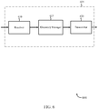
- FIG. 6 shows a block diagram 600 of an apparatus 605 for use in wireless communication, in accordance with various aspects of the present disclosure.
- the apparatus 605 may be an example of aspects of one or more of the base stations 105, 205, 305, and/or 405 described with reference to FIGs. 1 , 2 , 3 , and 4 , respectively.
- the apparatus 605 may be part of or include an LTE/LTE-A eNB and/or an LTE/LTE-A base station.
- the apparatus 605 may be a base station operating in a mmW wireless communication system.
- the apparatus 605 may also be a processor.
- the apparatus 605 may include a receiver 610, a discovery manager 615, and/or a transmitter 620. Each of these modules may be in communication with each other.
- the components of the apparatus 605 may, individually or collectively, be implemented using one or more ASICs adapted to perform some or all of the applicable functions in hardware. Alternatively, the functions may be performed by one or more other processing units (or cores), on one or more integrated circuits. In other examples, other types of integrated circuits may be used (e.g ., Structured/Platform ASICs, FPGAs, and other Semi-Custom ICs), which may be programmed in any manner known in the art. The functions of each component may also be implemented, in whole or in part, with instructions embodied in a memory, formatted to be executed by one or more general or application-specific processors.
- the receiver 610 may include at least one radio frequency (RF) receiver, such as an RF receiver operable to receive one or more messages associated with a discovery procedure for the apparatus 605.
- the receiver 610 may be used to receive various types of data and/or control signals (i.e., transmissions) over one or more communication links of a wireless communication system, such as one or more communication links of the wireless communications system 100 described with reference to FIG. 1 .
- the transmitter 620 may include at least one RF transmitter, such as at least one RF transmitter operable to transmit one or more messages associated with a discovery procedure for the apparatus 605.
- the transmitter 620 may be used to transmit various types of data and/or control signals ( i.e., transmissions) over one or more communication links of a wireless communication system, such as one or more communication links of the wireless communications system 100 described with reference to FIG. 1 .
- the discovery manager 615 may monitor, control, or otherwise manage one or more aspects of a discovery procedure for the apparatus 605.
- the apparatus 605 may be a mmW base station that seeks to initiate and perform a discovery procedure with a second mmW base station to establish a backhaul link for backhaul operations.
- the discovery manager 615 may determine a timing parameter, a propagation parameter, or both a timing and propagation parameters associated with the second mmW base station.
- the discovery manager 615 may also perform a discovery procedure with the second mmW base station based on the timing parameter and the propagation parameter. At least a portion of the discovery procedure may be performed wirelessly via the mmW wireless communication system.
- the discovery manager 615 may manage aspects of establishing a backhaul communication link with the second mmW base station based on the discovery procedure, e.g., a wireless backhaul communication link via the mmW wireless communication system.
- the apparatus 605 may perform various coordination functions with the second mmW base station via the backhaul communication link.
- the discovery manager 615 may determine a timing parameter associated with the second mmW base station, where the timing parameter is based on a frame timing attribute for communicating with the second mmW base station.
- the propagation parameter may, in certain examples, be based on a beamforming pattern for communicating with the second mmW base station.
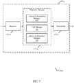
- FIG. 7 shows a block diagram 700 of an apparatus 605-a for use in wireless communication, in accordance with various aspects of the present disclosure.
- the apparatus 605-a may be an example of aspects of one or more of the base stations 105, 205, 305, and/or 405 described with reference to FIGs. 1 , 2 , 3 , and 4 , respectively.
- the apparatus 605-a may be an example of the apparatus 605 described with reference to FIG. 6 .
- the apparatus 605-a may be part of or include an LTE/LTE-A eNB and/or an LTE/LTE-A base station.
- the apparatus 605-a may be a base station operating in a mmW wireless communication system.
- the apparatus 605-a may also be a processor.
- the apparatus 605-a may include a receiver 610-a, a discovery manager 615-a, and/or a transmitter 620-a. Each of these modules may be in communication with each other.
- the receiver 610-a and the transmitter 620-a may be examples of and perform the functions of the receiver 610 and the transmitter 620, respectively, described with reference to FIG. 6 .
- the discovery manager 615-a may be an example of the discovery manager 615 described with reference to FIG. 6 and may include a timing and propagation manager 705, a link manager 710, and/or discovery procedure manager 715.
- the timing and propagation manager 705 may monitor, control, or otherwise manage aspects of determining a timing parameter and a propagation parameter associated with communicating with a second mmW base station.
- the timing parameter may be based on a frame timing attribute for communicating with the second mmW base station.
- Other examples of timing parameters may include beam sequencing timing information associated with one or more synchronization periods and/or access periods for the second mmW base station.
- the propagation parameter may, in certain examples, be based on a beamforming pattern for communicating with the second mmW base station.
- the timing and propagation manager 705 may cooperate with the link manager 710 to determine the timing and propagation parameters. For example, the timing and propagation manager 705 may, alone or in cooperation with one or more other components of the apparatus 605-a, cause the apparatus 605-a to refrain from transmitting a synchronization signal during a synchronization period and, instead, monitor during the synchronization period for a synchronization signal transmitted by the second base station.
- the timing and propagation manager 705 may initiate the discovery procedure based at least in part on the transmitted synchronization signal.
- the message to the second base station to initiate the discovery procedure may be sent via a downlink directional random access channel (DRACH).
- DRACH downlink directional random access channel
- the timing and propagation manager 705 may determine a predetermined periodicity associated with refraining from transmitting the synchronization signal and monitoring for the synchronization signal transmission from the second base station.
- the periodicity may be determined, at least in some examples, based at least in part on information received from a network entity.
- the synchronization signal transmitted from the second base station may be a directional primary synchronization signal (DPSS).
- DPSS directional primary synchronization signal
- the link manager 710 may monitor, control, or otherwise manage one or more aspects of identifying a link that may, in certain examples, be leveraged to determine aspects of the timing parameter and/or the propagation parameter for the apparatus 605-a.
- the link manager 710 may identify a network entity having a connection to the apparatus 605-a and the second mmW base station.
- the link manager 710 may receive information from the network entity indicative of at least one of the timing parameter, or the propagation parameter, or a combination thereof.
- the link manager 710 may, alone or in cooperation with the transmitter 620-a, transmit information to the network entity indicating a request to establish a backhaul communication link with the second base station.
- the link manager 710 may determine that the network entity is connected to the apparatus 605-a and the second base station via a wired communication link, e.g., an Ethernet communication link. Additionally or alternatively, the link manager 710 may determine the network entity is connected to the apparatus 605-a and the second base station via a wireless communication link associated with a third base station of the millimeter wave wireless communication system. That is, the apparatus 605-a may be in communication, e.g ., via a backhaul link, with a third mmW base station and leverage the link to determine aspects of the timing parameter and/or the propagation parameter.
- a wired communication link e.g., an Ethernet communication link.
- the link manager 710 may determine the network entity is connected to the apparatus 605-a and the second base station via a wireless communication link associated with a third base station of the millimeter wave wireless communication system. That is, the apparatus 605-a may be in communication, e.g ., via a backhaul link, with a third
- the information received from the network entity indicative of at least one of the timing parameter or the propagation parameter may be based on a previous backhaul communication link of the apparatus 605-a or the second base station, or a geographic location of the apparatus 605-a and the second base station, or a message received from one or more user equipments (UEs) associated with communications via the apparatus 605-a or the second base station, or combinations thereof.
- the information received from the network entity may also include additional communication parameters associated with the second mmW base station.
- Examples include, but are not limited to, an indication of a timing window parameter associated with a timing window for attempting to perform the discovery procedure, a search beam parameter associated with a quantity of beams being transmitted by the second base station, a sequence parameter associated with a transmission sequence of the second base station, a base station capabilities parameter identifying one or more capabilities of the second base station, or combinations thereof.
- the link manager 710 may determine that at least one user equipment (UE) is in communication with the apparatus 605-a and the second base station and, relay one or more messages to the second base station through the at least one UE to determine at least one of the timing parameter or the propagation parameter associated with the second base station. Accordingly, the link manager 710 may, alone or in cooperation with the receiver 610-a, receive one or more messages from the UE including information associated with the second base station, and determine to perform the discovery procedure based at least in part on the one or more messages received from the UE.
- UE user equipment
- the information received from the UE associated with the second base station may also include an indication of a timing window parameter associated with a timing window for attempting to perform the discovery procedure, a search beam parameter associated with a quantity of beams being transmitted by the second base station, a sequence parameter associated with a transmission sequence of the second base station, a base station capabilities parameter identifying one or more capabilities of the second base station, or combinations thereof.
- the at least one UE may, in some examples, be in communication with the apparatus 605-a and the second base station via a wireless communication link of the millimeter wave wireless communication system.
- the discovery procedure manager 715 may monitor, control, or otherwise manage aspects of performing a discovery procedure for the apparatus 605-a.
- the discovery procedure may be performed with the second mmW base station and, in some example, be performed wirelessly via the mmW wireless communication system.
- the discovery procedure manager 715 may utilize the timing parameter to determine a frame timing attribute for communicating with the second mmW base station, to determine a synchronization signal transmission time or pattern from the second mmW base station, etc.
- the discovery procedure manager 715 may utilize the propagation parameter to determine a beamforming direction for communication with the second mmW base station.
- the discovery procedure manager 715 may, alone or in cooperation with the other components of the apparatus 605-a, initiate and perform a discovery procedure with the second mmW base station to determine communication parameters associated with establishing a backhaul communication link for performing backhaul operations.
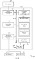
- FIG. 8 shows a block diagram 800 of a base station 105-a (e.g., a base station forming part or all of an eNB) for use in wireless communication, in accordance with various aspects of the present disclosure.
- the base station 105-a may be an example of aspects of one or more of the base stations 105 described with reference to FIG. 1 , aspects of one or more of the first base stations 205, 305, and 405, described with reference to FIGs. 2 , 3 , and 4 , respectively, and/or aspects of one or more of the apparatus 605 when configured as a base station, as described with reference to FIGs. 6 and/or 7.
- the base station 105-a may be configured to implement or facilitate at least some of the base station and/or apparatus features and functions described with reference to FIGs. 1-7 .
- the base station 105-a may include a base station processor 810, a base station memory 820, at least one base station transceiver (represented by base station transceiver 850), at least one base station antenna (represented by base station antenna(s) 855), and/or a discovery manager 615-b.
- the base station 105-a may also include one or more of a base station communications manager 830 and/or a network communications manager 840. Each of these modules may be in communication with each other, directly or indirectly, over one or more buses 835.
- the base station memory 820 may include random access memory (RAM) and/or read-only memory (ROM).
- the base station memory 820 may store computer-readable, computer-executable software/firmware code 825 containing instructions that are configured to, when executed, cause the base station processor 810 to perform various functions described herein related to wireless communication (e.g ., to perform discovery operations in a millimeter wave wireless communication system, etc. ) .
- the computer-readable, computer-executable software/firmware code 825 may not be directly executable by the base station processor 810 but may be configured to cause the base station 105-a ( e.g., when compiled and executed) to perform various of the functions described herein.
- the base station processor 810 may include an intelligent hardware device, e.g., a central processing unit (CPU), a microcontroller, an ASIC, etc.
- the base station processor 810 may process information received through the base station transceiver 850, the base station communications manager 830, and/or the network communications manager 840.
- the base station processor 810 may also process information to be sent to the transceiver 850 for transmission through the antenna(s) 855, to the base station communications manager 830, for transmission to one or more other base stations 105-b and 105-c, and/or to the network communications manager 840 for transmission to a core network 845, which may be an example of one or more aspects of the core network 130 described with reference to FIG. 1 .
- the base station processor 810 may handle, alone or in connection with the discovery manager 615-b, various aspects of discovery procedures for the base station 105-a.
- the base station transceiver 850 may include a modem configured to modulate packets and provide the modulated packets to the base station antenna(s) 855 for transmission, and to demodulate packets received from the base station antenna(s) 855.
- the base station transceiver 850 may, in some examples, be implemented as one or more base station transmitter modules and one or more separate base station receiver modules.
- the base station transceiver 850 may support communications in a first radio frequency spectrum band and/or a second radio frequency spectrum band.
- the base station transceiver 850 may be configured to communicate bi-directionally, via the antenna(s) 855, with one or more UEs or apparatuses, such as one or more of the UEs 115 described with reference to FIGs. 1-5 .
- the base station 105-a may, for example, include multiple base station antennas 855 (e.g., an antenna array).
- the base station 105-a may communicate with the core network 845 through the network communications manager 840.
- the base station 105-a may also communicate with other base stations, such as the base stations 105-b and 105-c, using the base station communications manager 830.
- the discovery manager 615-b may be configured to perform and/or control some or all of the features and/or functions described with reference to FIGs. 1-7 related to discovery operations for the base station 105-a.
- the discovery manager 615-b may determine timing and/or propagation parameters associated with a second mmW base station and perform a discovery procedure with the second mmW base station.
- the discovery manager 615-b, or portions thereof, may include a processor, and/or some or all of the functions of the discovery manager 615-b may be performed by the base station processor 810 and/or in connection with the base station processor 810.
- the discovery manager 615-b may be an example of the discovery manager 615 described with reference to FIGs. 6 and/or 7.
- the discovery manager 615-b may include a link manager 710-a and a discovery procedure manager 715-a, which may be examples of and perform the functions of the link manager 710 and the discovery procedure manager 715, respectively, described with reference to FIG. 7 .
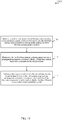
- FIG. 9 is a flow chart illustrating an example of a method 900 for wireless communication, in accordance with various aspects of the present disclosure.
- the method 900 is described below with reference to aspects of one or more of the base stations 105, 205, 305, 405 described with reference to FIGs. 1 , 2 , 3 , 4 , and 8 , respectively, and/or aspects of one or more of the apparatuses 605 described with reference to FIGs. 6 and 7 .
- a base station may execute one or more sets of codes to control the functional elements of the base station to perform the functions described below. Additionally or alternatively, the base station may perform one or more of the functions described below using special-purpose hardware.
- the method 900 may include a first base station of a mmW wireless communication system determining a timing parameter and a propagation parameter associated with a second base station of the mmW wireless communication system.
- the timing parameter may include a frame timing attribute, a synchronization signal transmission timing attribute, and the like.
- the propagation parameter may include a beamforming parameter, a beam sequence, and the like, associated with communicating with the second base station.
- the method 900 may include the first base station performing a discovery procedure with the second base station based at least in part on the timing parameter and the propagation parameter.
- at least a portion of the discovery procedure may be performed wirelessly via the mmW wireless communication system.
- the discovery procedure may include the first base station determining additional communication parameters associated with communicating with the second base station, e.g., MCS parameters, base station capability parameters, etc.
- the operation(s) at block 905 and/or 910 may be performed using the discovery manager 615 described with reference to FIGs. 6-8 .
- the method 900 may provide for wireless communication. It should be noted that the method 900 is just one implementation and that the operations of the method 900 may be rearranged or otherwise modified such that other implementations are possible.
- FIG. 10 is a flow chart illustrating an example of a method 1000 for wireless communication, in accordance with various aspects of the present disclosure.
- the method 1000 is described below with reference to aspects of one or more of the base stations 105, 205, 305, 405 described with reference to FIGs. 1 , 2 , 3 , 4 , and 8 , respectively, and/or aspects of one or more of the apparatuses 605 described with reference to FIGs. 6 and 7 .
- a base station may execute one or more sets of codes to control the functional elements of the base station to perform the functions described below. Additionally or alternatively, the base station may perform one or more of the functions described below using special-purpose hardware.
- the method 1000 may include a first base station of a mmW wireless communication system determining a timing parameter and a propagation parameter associated with a second base station of the mmW wireless communication system.
- the timing parameter may include a frame timing attribute, a synchronization signal transmission timing attribute, and the like.
- the propagation parameter may include a beamforming parameter, a beam sequence, and the like, associated with communicating with the second base station.
- the method 1000 may include the first base station performing a discovery procedure with the second base station based at least in part on the timing parameter and the propagation parameter.
- at least a portion of the discovery procedure may be performed wirelessly via the mmW wireless communication system.
- the discovery procedure may include the first base station determining additional communication parameters associated with communicating with the second base station, e.g ., MCS parameters, base station capability parameters, etc.
- the method 1000 may include the first base station establishing a backhaul communication link with the second base station based at least in part on the discovery procedure.
- the discovery procedure may provide the additional communication parameters for establishing the backhaul communication link via the mmW wireless communication system.
- the first base station may perform various coordination functions with the second base station via the backhaul communication link.
- the operation(s) at block 1005, 1010, and/or 1015 may be performed using the discovery manager 615 described with reference to FIGs. 6-8 .
- the method 1000 may provide for wireless communication. It should be noted that the method 1000 is just one implementation and that the operations of the method 1000 may be rearranged or otherwise modified such that other implementations are possible.
- FIG. 11 is a flow chart illustrating an example of a method 1100 for wireless communication, in accordance with various aspects of the present disclosure.
- the method 1100 is described below with reference to aspects of one or more of the base stations 105, 205, 305, 405 described with reference to FIGs. 1 , 2 , 3 , 4 , and 8 , respectively, and/or aspects of one or more of the apparatuses 605 described with reference to FIGs. 6 and 7 .
- a base station may execute one or more sets of codes to control the functional elements of the base station to perform the functions described below. Additionally or alternatively, the base station may perform one or more of the functions described below using special-purpose hardware.
- the method 1100 may include a first base station of a mmW wireless communication system identifying a link in connection with a second base station of the mmW wireless communication system.
- the link may include a wired and/or wireless link to a network entity, a third base station of the mmW wireless communication system, one or more UEs in communication with the first base station and the second base station, or combinations thereof.
- the method 1100 may include the first base station determining a timing parameter and a propagation parameter associated with the second base station.
- the first base station may determine the timing and propagation parameters based on the identified link, e.g., via one or more messages exchanged with, or routed through the link.
- the method 1100 may include the first base station performing a discovery procedure with the second base station based at least in part on the timing parameter and the propagation parameter.
- at least a portion of the discovery procedure may be performed wirelessly via the mmW wireless communication system.
- the discovery procedure may include the first base station determining additional communication parameters associated with communicating with the second base station, e.g ., MCS parameters, base station capability parameters, etc.
- the operation(s) at block 1105, 1110, and/or 1115 may be performed using the discovery manager 615 described with reference to FIGs. 6-8 .
- the method 1100 may provide for wireless communication. It should be noted that the method 1100 is just one implementation and that the operations of the method 1100 may be rearranged or otherwise modified such that other implementations are possible.
- aspects from two or more of the methods 900, 1000, 1100 may be combined. It should be noted that the methods 900, 1000, etc. are just example implementations, and that the operations of the methods 900-1100 may be rearranged or otherwise modified such that other implementations are possible.
- a CDMA system may implement a radio technology such as CDMA2000, Universal Terrestrial Radio Access (UTRA), etc.
- CDMA2000 covers IS-2000, IS-95, and IS-856 standards.
- IS-2000 Releases 0 and A are commonly referred to as CDMA2000 IX, IX, etc.
- IS-856 (TIA-856) is commonly referred to as CDMA2000 1xEV-DO, High Rate Packet Data (HRPD), etc.
- UTRA includes Wideband CDMA (WCDMA) and other variants of CDMA.
- a TDMA system may implement a radio technology such as Global System for Mobile Communications (GSM).
- GSM Global System for Mobile Communications
- An OFDMA system may implement a radio technology such as Ultra Mobile Broadband (UMB), Evolved UTRA (E-UTRA), IEEE 802.11 (WiFi), IEEE 802.16 (WiMAX), IEEE 802.20, Flash-OFDMTM, etc.
- UMB Ultra Mobile Broadband
- E-UTRA Evolved UTRA
- WiFi WiFi
- WiMAX IEEE 802.16
- IEEE 802.20 Flash-OFDMTM
- UTRA and E-UTRA are part of Universal Mobile Telecommunication System (UMTS).
- 3GPP Long Term Evolution (LTE) and LTE-Advanced (LTE-A) are new releases of UMTS that use E-UTRA.
- UTRA, E-UTRA, UMTS, LTE, LTE-A, and GSM are described in documents from an organization named "3rd Generation Partnership Project" (3GPP).
- CDMA2000 and UMB are described in documents from an organization named "3rd Generation Partnership Project 2" (3GPP2).
- 3GPP2 3rd Generation Partnership Project 2
- the techniques described herein may be used for the systems and radio technologies mentioned above as well as other systems and radio technologies, including cellular (e.g., LTE) communications over an unlicensed and/or shared bandwidth.
- LTE Long Term Evolution
- the description above describes an LTE/LTE-A system for purposes of example, and LTE terminology is used in much of the description above, although the techniques are applicable beyond LTE/LTE-A applications.
- Information and signals may be represented using any of a variety of different technologies and techniques.
- data, instructions, commands, information, signals, bits, symbols, and chips that may be referenced throughout the above description may be represented by voltages, currents, electromagnetic waves, magnetic fields or particles, optical fields or particles, or any combination thereof.
- a general-purpose processor may be a microprocessor, but in the alternative, the processor may be any conventional processor, controller, microcontroller, or state machine.
- a processor may also be implemented as a combination of computing devices, e.g., a combination of a DSP and a microprocessor, multiple microprocessors, one or more microprocessors in conjunction with a DSP core, or any other such configuration.
- the functions described herein may be implemented in hardware, software executed by a processor, firmware, or any combination thereof. If implemented in software executed by a processor, the functions may be stored on or transmitted over as one or more instructions or code on a computer-readable medium. Other examples and implementations are within the scope and spirit of the disclosure and appended claims. For example, due to the nature of software, functions described above can be implemented using software executed by a processor, hardware, firmware, hardwiring, or combinations of any of these. Features implementing functions may also be physically located at various positions, including being distributed such that portions of functions are implemented at different physical locations.
- the term "and/or,” when used in a list of two or more items, means that any one of the listed items can be employed by itself, or any combination of two or more of the listed items can be employed.
- the composition can contain A alone; B alone; C alone; A and B in combination; A and C in combination; B and C in combination; or A, B, and C in combination.
- Computer-readable media includes both computer storage media and communication media including any medium that facilitates transfer of a computer program from one place to another.
- a storage medium may be any available medium that can be accessed by a general purpose or special purpose computer.
- computer-readable media can comprise RAM, ROM, EEPROM, flash memory, CD-ROM or other optical disk storage, magnetic disk storage or other magnetic storage devices, or any other medium that can be used to carry or store desired program code means in the form of instructions or data structures and that can be accessed by a general-purpose or special-purpose computer, or a general-purpose or special-purpose processor.
- any connection is properly termed a computer-readable medium.
- Disk and disc include compact disc (CD), laser disc, optical disc, digital versatile disc (DVD), floppy disk and Blu-ray disc where disks usually reproduce data magnetically, while discs reproduce data optically with lasers. Combinations of the above are also included within the scope of computer-readable media.
Description
- The present disclosure, for example, relates to wireless communication systems, and more particularly to backhaul operations in a millimeter wave wireless communication system.
- Wireless communication systems are widely deployed to provide various types of communication content such as voice, video, packet data, messaging, broadcast, and so on. These systems may be multiple-access systems capable of supporting communication with multiple users by sharing the available system resources (e.g., time, frequency, and power). Examples of such multiple-access systems include code-division multiple access (CDMA) systems, time-division multiple access (TDMA) systems, frequency-division multiple access (FDMA) systems, and orthogonal frequency-division multiple access (OFDMA) systems.
- By way of example, a wireless multiple-access communication system may include a number of base stations, each simultaneously supporting communication for multiple communication devices, otherwise known as user equipments (UEs). A base station may communicate with UEs on downlink channels (e.g., for transmissions from a base station to a UE) and uplink channels (e.g., for transmissions from a UE to a base station). A base station may communicate, either directly or indirectly with other base stations over backhaul links.
- A base station, in a conventional communication system, typically enjoys a robust link to a network entity which coordinates aspects of the discovery and backhaul communications, e.g., the network entity provides timing information, cell identity, etc., for neighboring base stations to coordinate discovery and backhaul transmissions. Base stations operating in the millimeter wave (mmW) frequency ranges, e.g., 28 GHz, 40 GHz, 60 GHz, etc., may be associated with a reduced coverage area (e.g., a smaller geographic footprint, directional transmissions only, etc.), which may result in deployment of a much larger number of base stations to provide acceptable coverage areas. Such large-scale mmW base station deployments may impact the quality and availability of links to a network entity. For example, some mmW base stations may be deployed in areas with limited bandwidth links to a network entity and, in some examples, no links to a network entity. In a conventional cellular communication system, base stations may rely on a wired connection to a network entity and, therefore, may not typically perform discovery over the wireless medium. Such mmW base stations with limited or no links to a network entity still have a need to be able to discover other mmW base stations in order to perform backhaul operations. Moreover, such wireless discovery operations may provide a more beneficial deployment scheme for a dense population of mmW base stations, e.g., provide a lower cost and more feasible option to installing fiber optic communication lines to each mmW base station.
- Document
WO 2014/036059 A1 relates to methods for implement granting a license to a millimeter wave base station (mB) in a wireless network. The mB may send a license request. The license request may be associated with a beam direction in a frequency band. The mB may receive a measurement schedule. The mB may take an interference measurement, e.g., in accordance with the measurement schedule. The interference measurement may be associated with one or more of the beam direction, a frequency band, or an assigned time period. The mB may send the interference measurement to the license coordinator. The mB may receive a temporary license for the beam direction in the frequency band. The temporary license may include a first transmit power restriction. The mB may receive an instruction to send a signal burst. The mB may receive a non-temporary license. The non-temporary license may include a second transmit power restriction. - Document
US 2013/ 0237218 A1 relates to a mobile station being configured to scan cells in a wireless network. The mobile station includes at least one antenna configured to transmit and receive wireless signals. The mobile station also includes a processor coupled to the at least one antenna, the processor configured to scan for one or more neighboring base station cells in a same frequency band as a serving base station cell using one or more receive beams. The one or more receive beams used for scanning are different than receive beams used for data communication with the serving base station cell. - Document
WO 2014/124048 A1 relates to a method for association in a mesh network. A method in a new node may include performing a discovery procedure with a plurality of peer nodes in the mesh network, initiating a temporary association procedure with each peer node, selecting a set of peer nodes from the plurality of peer nodes based on a selection algorithm at least based on a signal-to-interference and noise ratio (SINR) with each peer node and an interference impact of each peer node, and performing a final association with the selected set of peer nodes. - The invention is defined by the independent claims
- The described features generally relate to one or more improved systems, methods, and/or apparatuses for backhaul operations in a mmW wireless communication system. Certain aspects of the present description employ various approaches for a mmW base station to determine certain parameters associated with another mmW base station to perform a discovery procedure. For example, a first mmW base station may access, identify, or otherwise determine parameters for a second mmW base station associated with timing, propagation, and the like, e.g., a first set of communication parameters for the second mmW base station. The first set of communication parameters may include a sufficient amount of information associated with the second mmW base station to permit the first mmW base station to initiate a discovery procedure with the second base station. The discovery procedure, or at least a portion thereof, may be performed via the mmW wireless communication system.
- In certain aspects, the first mmW base station may determine the first set of communication parameters using a blind detection mode, using a network-assisted mode, using a UE assisted mode, or combinations thereof. An example of a blind detection mode may include the first base station refraining from transmitting a synchronization signal during a synchronization period and, instead, listening for a synchronization signal from the second base station. A detected synchronization signal from the second base station may provide sufficient information for the second base station to permit the first base station to initiate the discovery procedure. An example of a network assisted mode may include the first base station utilizing a limited link (e.g., low bandwidth link, data limited link, etc.) with a network entity to determine the first set of communication parameters. An example of a UE assisted mode may include identifying a UE that is in communication with the first base station and the second base station. The first base station may leverage the UE to exchange information with the second base station to determine the first set of communication parameters. Generally, during the discovery procedure, the first base station may identify or determine additional communication parameters associated with the second base station, e.g., a second set of communication parameters. Examples of the second set of communication parameters may include modulation-coding schemes (MCS), frame alignment timing information, beacon transmission timing information, etc.
- In a first illustrative set of examples, a method for wireless communication in a millimeter wave wireless communication system is described. The method may include: determining, by a first base station of the millimeter wave wireless communication system, a timing parameter and a propagation parameter associated with a second base station of the millimeter wave wireless communication system; and performing a discovery procedure with the second base station based at least in part on the timing parameter and the propagation parameter, wherein at least a portion of the discovery procedure is performed wirelessly via the millimeter wave wireless communication system.
- In some examples, the method may include: identifying a network entity having a connection to the first base station and the second base station; and receiving information from the network entity indicative of at least one of the timing parameter, or the propagation parameter, or a combination thereof. The method may include transmitting information to the network entity indicating a request to establish a backhaul communication link with the second base station. The network entity may be connected to the first base station and the second base station via a wired communication link. The network entity may be connected to the first base station and the second base station via a wireless communication link associated with a third base station of the millimeter wave wireless communication system.
- In some examples, the information received from the network entity indicative of at least one of the timing parameter or the propagation parameter may be based at least in part on a previous backhaul communication link of the first base station or the second base station, or a geographic location of the first base station and the second base station, or a message received from one or more user equipments (UEs) associated with communications via the first base station or the second base station, or combinations thereof. The information received from the network entity may include an indication of a timing window parameter associated with a timing window for attempting to perform the discovery procedure, a search beam parameter associated with a quantity of beams being transmitted by the second base station, a sequence parameter associated with a transmission sequence of the second base station, a base station capabilities parameter identifying one or more capabilities of the second base station, or combinations thereof.
- In some examples, the method may include: refraining, by the first base station, from transmitting a synchronization signal during a synchronization period; and monitoring, by the first base station during the synchronization period, for a synchronization signal transmitted by the second base station. The method may include, upon determining that the second base station has transmitted a synchronization signal, initiating the discovery procedure based at least in part on the transmitted synchronization signal. The message to the second base station to initiate the discovery procedure may be sent via a directional random access channel (DRACH).
- In some examples, the method may include determining, by the first base station, a predetermined periodicity associated with refraining from transmitting the synchronization signal and monitoring for the synchronization signal transmission from the second base station. The predetermined periodicity may be determined based at least in part on information received from a network entity. The synchronization signal transmitted from the second base station may include a directional primary synchronization signal (DPSS).
- In some examples, the method may include: determining, by the first base station, that at least one user equipment (UE) is in communication with the first base station and the second base station; and relaying one or more messages to the second base station through the at least one UE to determine at least one of the timing parameter or the propagation parameter associated with the second base station. The method may include: receiving one or more messages from the UE including information associated with the second base station; and determining to perform the discovery procedure based at least in part on the one or more messages received from the UE.
- In some examples, the information received from the UE associated with the second base station may include an indication of a timing window parameter associated with a timing window for attempting to perform the discovery procedure, a search beam parameter associated with a quantity of beams being transmitted by the second base station, a sequence parameter associated with a transmission sequence of the second base station, a base station capabilities parameter identifying one or more capabilities of the second base station, or combinations thereof. The at least one UE may be in communication with the first base station and the second base station via a wireless communication link of the millimeter wave wireless communication system. The method may include establishing a backhaul communication link with the second base station based at least in part on the discovery procedure.
- In some examples, the backhaul communication link may be a wireless backhaul communication link established via the millimeter wave wireless communication system. The method may include performing one or more coordination functions with the second base station via the backhaul communication link. The timing parameter may be based at least in part on a frame timing for communications associated with the second base station of the millimeter wave wireless communication system. The propagation parameter may be based at least in part on a beamforming pattern for communications between the first base station and the second base station.
- In a second illustrative set of examples, an apparatus for wireless communication is described. The apparatus may include a first base station of a millimeter wave wireless communication system. The apparatus may include: a processor; memory in electronic communication with the processor; and instructions stored in the memory. The instructions being executable by the processor to: determine, by a first base station of the millimeter wave wireless communication system, a timing parameter and a propagation parameter associated with a second base station of the millimeter wave wireless communication system; and perform a discovery procedure with the second base station based at least in part on the timing parameter and the propagation parameter, wherein at least a portion of the discovery procedure is performed wirelessly via the millimeter wave wireless communication system.
- In some examples, the apparatus may include instructions executable by the processor to: identify a network entity having a connection to the first base station and the second base station; and receive information from the network entity indicative of at least one of the timing parameter, or the propagation parameter, or a combination thereof. The apparatus may include instructions executable by the processor to transmit information to the network entity indicating a request to establish a backhaul communication link with the second base station. The network entity may be connected to the first base station and the second base station via a wired communication link. The network entity may be connected to the first base station and the second base station via a wireless communication link associated with a third base station of the millimeter wave wireless communication system.
- In some examples, the information received from the network entity indicative of at least one of the timing parameter or the propagation parameter is based at least in part on a previous backhaul communication link of the first base station or the second base station, or a geographic location of the first base station and the second base station, or a message received from one or more user equipments (UEs) associated with communications via the first base station or the second base station, or combinations thereof. The information received from the network entity may include an indication of a timing window parameter associated with a timing window for attempting to perform the discovery procedure, a search beam parameter associated with a quantity of beams being transmitted by the second base station, a sequence parameter associated with a transmission sequence of the second base station, a base station capabilities parameter identifying one or more capabilities of the second base station, or combinations thereof.
- In some examples, the apparatus may include instructions executable by the processor to: refrain, by the first base station, from transmitting a synchronization signal during a synchronization period; and monitor, by the first base station during the synchronization period, for a synchronization signal transmitted by the second base station. The apparatus may include instructions executable by the processor to, upon determining that the second base station has transmitted a synchronization signal, initiate the discovery procedure based at least in part on the transmitted synchronization signal. The message to the second base station to initiate the discovery procedure may be sent via a directional random access channel (DRACH). The apparatus may include instructions executable by the processor to determine, by the first base station, a predetermined periodicity associated with refraining from transmitting the synchronization signal and monitoring for the synchronization signal transmission from the second base station.
- In some examples, the predetermined periodicity is determined based at least in part on information received from a network entity. The synchronization signal transmitted from the second base station may include a directional primary synchronization signal (DPSS). The apparatus may include instructions executable by the processor to determine, by the first base station, that at least one user equipment (UE) is in communication with the first base station and the second base station; and relay one or more messages to the second base station through the at least one UE to determine at least one of the timing parameter or the propagation parameter associated with the second base station.
- In some examples, the apparatus may include instructions executable by the processor to: receive one or more messages from the UE including information associated with the second base station; and determine to perform the discovery procedure based at least in part on the one or more messages received from the UE. The information received from the UE associated with the second base station may include an indication of a timing window parameter associated with a timing window for attempting to perform the discovery procedure, a search beam parameter associated with a quantity of beams being transmitted by the second base station, a sequence parameter associated with a transmission sequence of the second base station, a base station capabilities parameter identifying one or more capabilities of the second base station, or combinations thereof.
- In some examples, the at least one UE is in communication with the first base station and the second base station via a wireless communication link of the millimeter wave wireless communication system. The apparatus may include instructions executable by the processor to establish a backhaul communication link with the second base station based at least in part on the discovery procedure. The backhaul communication link may be a wireless backhaul communication link established via the millimeter wave wireless communication system. The apparatus may include instructions executable by the processor to perform one or more coordination functions with the second base station via the backhaul communication link.
- In some examples, the timing parameter is based at least in part on a frame timing for communications associated with the second base station of the millimeter wave wireless communication system. The propagation parameter may be based at least in part on a beamforming pattern for communications between the first base station and the second base station.
- In a third illustrative set of examples, an apparatus for wireless communication is described. The apparatus may include a first base station of a millimeter wave wireless communication system. The apparatus may include: means for determining, by a first base station of the millimeter wave wireless communication system, a timing parameter and a propagation parameter associated with a second base station of the millimeter wave wireless communication system; and means for performing a discovery procedure with the second base station based at least in part on the timing parameter and the propagation parameter, wherein at least a portion of the discovery procedure is performed wirelessly via the millimeter wave wireless communication system.
- In some examples, the apparatus may include means for identifying a network entity having a connection to the first base station and the second base station; and means for receiving information from the network entity indicative of at least one of the timing parameter, or the propagation parameter, or a combination thereof. The apparatus may include means for transmitting information to the network entity indicating a request to establish a backhaul communication link with the second base station.
- In a fourth illustrative set of examples, a non-transitory computer-readable medium storing computer-executable code for wireless communication is described. The code executable by a processor to: determine, by a first base station of the millimeter wave wireless communication system, a timing parameter and a propagation parameter associated with a second base station of the millimeter wave wireless communication system; and perform a discovery procedure with the second base station based at least in part on the timing parameter and the propagation parameter, wherein at least a portion of the discovery procedure is performed wirelessly via the millimeter wave wireless communication system.
- The foregoing has outlined rather broadly the features and technical advantages of examples according to the disclosure in order that the detailed description that follows may be better understood. Additional features and advantages will be described hereinafter. The conception and specific examples disclosed may be readily utilized as a basis for modifying or designing other structures for carrying out the same purposes of the present disclosure.
- Characteristics of the concepts disclosed herein, both their organization and method of operation, together with associated advantages will be better understood from the following description when considered in connection with the accompanying figures. Each of the figures is provided for the purpose of illustration and description only, and not as a definition of the limits of the claims.
- A further understanding of the nature and advantages of the present invention may be realized by reference to the following drawings. In the appended figures, similar components or features may have the same reference label. Further, various components of the same type may be distinguished by following the reference label by a dash and a second label that distinguishes among the similar components. If only the first reference label is used in the specification, the description is applicable to any one of the similar components having the same first reference label irrespective of the second reference label.
-
FIG. 1 shows a block diagram of a wireless communication system, in accordance with various aspects of the present disclosure; -
FIG. 2 shows a swim diagram illustrating aspects of discovery operations in wireless communication, in accordance with various aspects of the present disclosure; -
FIG. 3 shows a swim diagram illustrating aspects of discovery operations in wireless communication, in accordance with various aspects of the present disclosure; -
FIG. 4 shows a swim diagram illustrating aspects of discovery operations in wireless communication, in accordance with various aspects of the present disclosure; -
FIG. 5 shows a diagram of aspects of an example discovery operation in wireless communication, in accordance with various aspects of the present disclosure; -
FIG. 6 shows a block diagram of an apparatus for use in wireless communication, in accordance with various aspects of the present disclosure; -
FIG. 7 shows a block diagram of an apparatus for use in wireless communication, in accordance with various aspects of the present disclosure; -
FIG. 8 shows a block diagram of a base station (e.g., a base station forming part or all of an eNB) for use in wireless communication, in accordance with various aspects of the present disclosure; -
FIG. 9 is a flow chart illustrating an example of a method for wireless communication, in accordance with various aspects of the present disclosure; -
FIG. 10 is a flow chart illustrating another example of a method for wireless communication, in accordance with various aspects of the present disclosure; and -
FIG. 11 is a flow chart illustrating another example of a method for wireless communication, in accordance with various aspects of the present disclosure. - Next generation cellular communication systems may utilize mmW wireless communication channels. Such mmW communication channels may involve using frequencies in the 20+ GHz range, which requires additional considerations in the development and deployment of the infrastructure components. For example, mmW wireless links tend to have a smaller geographic coverage area and often require use of directional transmissions. In order to provide wide scale coverage, a more dense population of mmW base stations may be deployed, with respect to traditional macro base stations for existing cellular communication systems. In some environments, it may not be reasonable from a cost and/or feasibility perspective, to deploy high speed wired communication links to every mmW base station. For example, not every deployment location will be suitable for a strong communication link between the mmW base station and a network entity. Such mmW base stations with limited or no direct links to a network entity will, therefore, establish direct links with one or more neighboring mmW base stations to access network functionality and perform traditional backhaul operations. Discovering such neighboring base stations, however, can be problematic in a mmW infrastructure due to the limited (or no) access to a network entity.
- According to aspects of the present description, in high frequency systems (e.g., millimeter wave communication systems), a base station may determine certain communication parameters associated with a second base station in order to initiate a discovery procedure with the second base station. For example, given the directional nature of mmW communications, a first base station may determine a propagation parameter associated with the second base station, e.g., to know which direction the second base station is in relation to the first base station. Additionally or alternatively, the first base station may determine a timing parameter associated with the second base station, e.g., an indication of synchronization signal transmission timing by the second base station. The propagation and timing parameters may provide sufficient information for the first base station to initiate a discovery procedure with the second base station. During the discovery procedure, the first base station may determine any remaining communication parameters necessary to establish a backhaul link with the second base station, e.g., frame timing and alignment information, MCS schemes, channel availability information, base station capabilities information, etc.
- The following description provides examples, and is not limiting of the scope, applicability, or examples set forth in the claims.
-
FIG. 1 illustrates an example of awireless communications system 100 in accordance with various aspects of the disclosure. Thewireless communications system 100 includesbase stations 105,UEs 115, and acore network 130. Thecore network 130 may provide user authentication, access authorization, tracking, Internet Protocol (IP) connectivity, and other access, routing, or mobility functions. Thebase stations 105 interface with thecore network 130 through backhaul links 132 (e.g., S1, etc.) and may perform radio configuration and scheduling for communication with theUEs 115, or may operate under the control of a base station controller (not shown). In various examples, thebase stations 105 may communicate, either directly or indirectly (e.g., through core network 130), with each other over backhaul links 134 (e.g., X1, etc.), which may be wired or wireless communication links. In some examples,certain base stations 105 may have no (or a limited) connection to thecore network 130 and, instead, rely on a direct wireless connection to a neighboringbase station 105 to perform discovery and backhaul operations. - The
base stations 105 may wirelessly communicate with theUEs 115 via one or more base station antennas. Each of thebase station 105 sites may provide communication coverage for a respectivegeographic coverage area 110. In some examples,base stations 105 may be referred to as a base transceiver station, a radio base station, an access point, a radio transceiver, a NodeB, eNodeB (eNB), Home NodeB, a Home eNodeB, or some other suitable terminology. Thegeographic coverage area 110 for abase station 105 may be divided into sectors making up only a portion of the coverage area (not shown). Thewireless communications system 100 may includebase stations 105 of different types (e.g., macro and/or small cell base stations). There may be overlappinggeographic coverage areas 110 for different technologies. - In some examples, the
wireless communications system 100 is an LTE/LTE-A network. In LTE/LTE-A networks, the term evolved Node B (eNB) may be generally used to describe thebase stations 105, while the term UE may be generally used to describe theUEs 115. Thewireless communications system 100 may be a Heterogeneous LTE/LTE-A network in which different types of eNBs provide coverage for various geographical regions. For example, each eNB orbase station 105 may provide communication coverage for a macro cell, a small cell, and/or other types of cell. The term "cell" is a 3GPP term that can be used to describe a base station, a carrier or component carrier associated with a base station, or a coverage area (e.g., sector, etc.) of a carrier or base station, depending on context. - A macro cell generally covers a relatively large geographic area (e.g., several kilometers in radius) and may allow unrestricted access by UEs with service subscriptions with the network provider. A small cell is a lower-powered base station, as compared with a macro cell, that may operate in the same or different (e.g., licensed, unlicensed, etc.) frequency bands as macro cells. Small cells may include pico cells, femto cells, and micro cells according to various examples. A pico cell may cover a relatively smaller geographic area and may allow unrestricted access by UEs with service subscriptions with the network provider. A femto cell also may cover a relatively small geographic area (e.g., a home) and may provide restricted access by UEs having an association with the femto cell (e.g., UEs in a closed subscriber group (CSG), UEs for users in the home, and the like). An eNB for a macro cell may be referred to as a macro eNB. An eNB for a small cell may be referred to as a small cell eNB, a pico eNB, a femto eNB or a home eNB. An eNB may support one or multiple (e.g., two, three, four, and the like) cells (e.g., component carriers).
- The
wireless communications system 100 may support synchronous or asynchronous operation. For synchronous operation, the base stations may have similar frame timing, and transmissions from different base stations may be approximately aligned in time. For asynchronous operation, the base stations may have different frame timing, and transmissions from different base stations may not be aligned in time. The techniques described herein may be used for either synchronous or asynchronous operations. - The communication networks that may accommodate some of the various disclosed examples may be packet-based networks that operate according to a layered protocol stack. In the user plane, communications at the bearer or Packet Data Convergence Protocol (PDCP) layer may be IP-based. A Radio Link Control (RLC) layer may perform packet segmentation and reassembly to communicate over logical channels. A Medium Access Control (MAC) layer may perform priority handling and multiplexing of logical channels into transport channels. The MAC layer may also use Hybrid ARQ (HARQ) to provide retransmission at the MAC layer to improve link efficiency. In the control plane, the Radio Resource Control (RRC) protocol layer may provide establishment, configuration, and maintenance of an RRC connection between a
UE 115 and thebase stations 105 orcore network 130 supporting radio bearers for the user plane data. At the Physical (PHY) layer, the transport channels may be mapped to Physical channels. - The
UEs 115 are dispersed throughout thewireless communications system 100, and eachUE 115 may be stationary or mobile. AUE 115 may also include or be referred to by those skilled in the art as a mobile station, a subscriber station, a mobile unit, a subscriber unit, a wireless unit, a remote unit, a mobile device, a wireless device, a wireless communications device, a remote device, a mobile subscriber station, an access terminal, a mobile terminal, a wireless terminal, a remote terminal, a handset, a user agent, a mobile client, a client, or some other suitable terminology. AUE 115 may be a cellular phone, a personal digital assistant (PDA), a wireless modem, a wireless communication device, a handheld device, a tablet computer, a laptop computer, a cordless phone, a wireless local loop (WLL) station, or the like. A UE may be able to communicate with various types of base stations and network equipment including macro eNBs, small cell eNBs, relay base stations, and the like. - The communication links 125 shown in
wireless communications system 100 may include uplink (UL) transmissions from aUE 115 to abase station 105, and/or downlink (DL) transmissions, from abase station 105 to aUE 115. The downlink transmissions may also be called forward link transmissions while the uplink transmissions may also be called reverse link transmissions. Eachcommunication link 125 may include one or more carriers, where each carrier may be a signal made up of multiple sub-carriers (e.g., waveform signals of different frequencies) modulated according to the various radio technologies described above. Each modulated signal may be sent on a different sub-carrier and may carry control information (e.g., reference signals, control channels, etc.), overhead information, user data, etc. The communication links 125 may transmit bidirectional communications using FDD (e.g., using paired spectrum resources) or TDD operation (e.g., using unpaired spectrum resources). Frame structures for FDD (e.g., frame structure type 1) and TDD (e.g., frame structure type 2) may be defined. - In some embodiments of the
system 100,base stations 105 and/orUEs 115 may include multiple antennas for employing antenna diversity schemes to improve communication quality and reliability betweenbase stations 105 andUEs 115. Additionally or alternatively,base stations 105 and/orUEs 115 may employ multiple-input, multiple-output (MIMO) techniques that may take advantage of multi-path environments to transmit multiple spatial layers carrying the same or different coded data. -
Wireless communications system 100 may support operation on multiple cells or carriers, a feature which may be referred to as carrier aggregation (CA) or multi-carrier operation. A carrier may also be referred to as a component carrier (CC), a layer, a channel, etc. The terms "carrier," "component carrier," "cell," and "channel" may be used interchangeably herein. AUE 115 may be configured with multiple downlink CCs and one or more uplink CCs for carrier aggregation. Carrier aggregation may be used with both FDD and TDD component carriers. -
Wireless communications system 100 may operate in an ultra high frequency (UHF) frequency region using frequency bands from 700 MHz to 2600 MHz (2.6 GHz), although in some cases WLAN networks may use frequencies as high as 4 GHz. This region may also be known as the decimeter band, since the wavelengths range from approximately one decimeter to one meter in length. UHF waves may propagate mainly by line of sight, and may be blocked by buildings and environmental features. However, the waves may penetrate walls sufficiently to provide service to UEs 115 located indoors. Transmission of UHF waves is characterized by smaller antennas and shorter range (e.g., less than 100 km) compared to transmission using the smaller frequencies (and longer waves) of the high frequency (HF) or very high frequency (VHF) portion of the spectrum. In some cases,wireless communications system 100 may also utilize extremely high frequency (EHF) portions of the spectrum (e.g., from 30 GHz to 300 GHz). This region may also be known as the millimeter wave band (or mmW), since the wavelengths range from approximately one millimeter to one centimeter in length. Thus, EHF antennas may be even smaller and more closely spaced than UHF antennas. In some cases, this may facilitate use of antenna arrays within a UE 115 (e.g., for directional beamforming). However, EHF transmissions may be subject to even greater atmospheric attenuation and shorter range than UHF transmissions. -
Wireless communications system 100 may support discovery procedures for millimeter wave communications. For example, a millimeterwave base station 105 may have no (or limited) connectivity to thecore network 130 and, therefore, perform a discovery procedure with a neighboring millimeterwave base station 105 to establish a backhaul link (e.g., the neighboring millimeterwave base station 105 may have robust connectivity to various network components). The first millimeterwave base station 105 may determine a propagation parameter and/or a timing parameter for the second (or neighboring) millimeter wave base station. The timing and propagation parameter may provide sufficient information for the first millimeterwave base station 105 to attempt to detect a beacon or synchronization signal from the second millimeter wave base station. The first millimeterwave base station 105 may initiate the discovery procedure based on the timing and/or the propagation parameters. - In some examples, the first millimeter
wave base station 105 may determine the timing and propagation parameters by accessing a network entity, e.g., using a limited or restricted link to the network entity. For example, the first millimeterwave base station 105 may send a message via the limited link to the network entity requesting information associated with neighboring base stations. The network entity may respond by sending the timing and/or propagation parameters. Another example may include the first millimeter wave base station 150 identifying aUE 115 in communication with the second millimeter wave base station. The first millimeterwave base station 105 may utilize communication link via the sharedUE 115 to determine the timing and/or propagation parameters. Other examples may include the first millimeterwave base station 105 blindly detecting the timing and/or propagation parameters based on resource partitioning schemes, e.g., partitioning access resources and backhaul resources. The first millimeterwave base station 105 may initiate a discovery procedure with the second millimeter wave base station using the determined parameters and, based on the discovery procedures, determine additional communication parameters associated with the second millimeter wave base station used for establishing a backhaul communication link. -
FIG. 2 is a swim diagram 200 illustrating aspects of discovery operations, in accordance with various aspects of the present disclosure. The diagram 200 may illustrate aspects of thesystem 100 described with reference toFIG. 1 . The diagram 200 includes a first millimeter wave (mmW)base station 205 and a secondmmW base station 210. The firstmmW base station 205 and/or the secondmmW base station 210 may be examples of one or more of thebase stations 105 described above with respect toFIG. 1 . Generally, the diagram 200 illustrates aspects of implementing discovery operations in millimeter wave communication systems. In some examples, a system device, such as one of thebase stations 105 may execute one or more sets of codes to control the functional elements of the device to perform some or all of the functions described below. - At
block 215, the firstmmW base station 205 may determine a timing parameter and a propagation parameter associated with thesecond base station 210. The timing parameter may include various timing components associated with communicating with the secondmmW base station 210. For example, the timing component may include information associated with scheduling for beacon and/or synchronization signals from thesecond base station 210. Other examples of timing parameters may include, but are not limited to, frame alignment and timing information, common synchronization timing information for the secondmmW base station 210, a timing window parameter associated with attempting to perform the discovery procedure with the secondmmW base station 210, and the like. The propagation parameter may include information associated with directional communications. Example propagation parameters may include, but are not limited to, a beamforming direction parameter based on the geographic locations of the firstmmW base station 205 and the secondmmW base station 210, a beam count parameter associated with one or more discovery beams (e.g., beacons and/or synchronization signals) transmitted by the secondmmW base station 210, and the like. - At
block 220, the firstmmW base station 205 may initiate adiscovery procedure 225 with the secondmmW base station 210. Thediscovery procedure 225 may be based on the determined timing parameter, the determined propagation parameter, or a combination of both. At least a portion of thediscovery procedure 225 may be performed wirelessly via the mmW wireless communication channel. -
FIG. 3 is a swim diagram 300 illustrating aspects of discovery operations, in accordance with various aspects of the present disclosure. The diagram 300 may illustrate aspects of thesystem 100 described with reference toFIG. 1 . The diagram 300 includes a first millimeter wave (mmW)base station 305, anetwork entity 310, and a secondmmW base station 315. The firstmmW base station 305 and/or the secondmmW base station 315 may be examples of one or more of thebase stations 105 described above with respect toFIG. 1 . Thenetwork entity 310 may be an example of thecore network 130 described above with respect toFIG. 1 . Generally, the diagram 300 illustrates aspects of implementing network assisted discovery operations in millimeter wave communication systems. In some examples, a system device, such as one of thebase stations 105 may execute one or more sets of codes to control the functional elements of the device to perform some or all of the functions described below. - At
block 320, the firstmmW base station 305 may identify a connection with thenetwork entity 310. The connection may be a direct connection to thenetwork entity 310 and/or an indirect connection via a third mmW base station (not shown). For a direct connection, the firstmmW base station 305 may have a limited connection that supports minimal data communications, e.g., via a low bandwidth connection and/or a restricted connection. The firstmmW base station 305 may identify the connection with thenetwork entity 310 that is also connected to the secondmmW base station 315. - At
block 325, the firstmmW base station 305 may receiveparameters 330 from thenetwork entity 310. The parameters may include at least one of a timing parameter associated with the secondmmW base station 315, a propagation parameter associated with the secondmmW base station 315, or both parameters. In some examples, the firstmmW base station 305 may send a message to thenetwork entity 310 indicating a need to perform a discovery procedure with the second mmW base station 315 (or any neighboring mmW base station). Thenetwork entity 310 may store information associated with mmW base stations, e.g., geographical location information, operational capabilities, communication parameters, etc., and identify the secondmmW base station 315 as a candidate for discovery and backhaul operations for the firstmmW base station 305. Accordingly, thenetwork entity 310 may select and send theparameters 330 to the firstmmW base station 305 associated with the secondmmW base station 315. - As previously discussed, the parameters sent may include a timing parameter and a propagation parameter associated with the second
mmW base station 315. The timing parameter may include various timing components associated with communicating with the secondmmW base station 315. The propagation parameter may include information associated with directional communications for the secondmmW base station 315. - At
block 335, the firstmmW base station 305 may initiate and perform adiscovery procedure 340 with the secondmmW base station 315. Thediscovery procedure 340 may be based on the timing parameter, the propagation parameter, or a combination of both. At least a portion of thediscovery procedure 340 may be performed wirelessly via the mmW wireless communication channel. The discovery procedure may, in some examples, permit the firstmmW base station 305 to determine additional (or any missing) communication parameters for communicating with the secondmmW base station 315, e.g., MCS parameters, channel availability and configurations, capability parameters, etc. Accordingly, the firstmmW base station 305 may, based at least in part on the discovery procedure, establish a backhaul link with the secondmmW base station 315 to perform backhaul operations. -
FIG. 4 is a swim diagram 400 illustrating aspects of discovery operations, in accordance with various aspects of the present disclosure. The diagram 400 may illustrate aspects of thesystem 100 described with reference toFIG. 1 . The diagram 400 includes a first millimeter wave (mmW)base station 405, aUE 410, and a secondmmW base station 415. The firstmmW base station 405 and/or the secondmmW base station 415 may be examples of one or more of thebase stations 105 described above with respect toFIG. 1 . TheUE 410 may be an example of the one or more of theUEs 115 described above with respect toFIG. 1 . Generally, the diagram 400 illustrates aspects of implementing UE assisted discovery operations in millimeter wave communication systems. In some examples, a system device, such as one of thebase stations 105 and/orUEs 115, may execute one or more sets of codes to control the functional elements of the device to perform some or all of the functions described below. - At
block 420, the firstmmW base station 405 may identify a common connection between the firstmmW base station 405, theUE 410, and the secondmmW base station 415. The common connection may be a direct connection to the secondmmW base station 415 through theUE 410 and/or an indirect connection via one or more additional UEs (not shown). Generally, the common connection via theUE 410 may support limited communications between the firstmmW base station 405 and the secondmmW base station 415. In some examples, theUE 410 may send a neighbor cell list (NCL) to the first mmW base station including information identifying the secondmmW base station 415, e.g., an identification information associated with the secondmmW base station 415. - At
block 425, the firstmmW base station 405 may relay a request to the secondmmW base station 415 via theUE 410. For example, the firstmmW base station 405 may send amessage 430 to theUE 410 requesting theUE 410 forward the message to the secondmmW base station 415. TheUE 410 may forward themessage 435 to the secondmmW base station 415. Generally, the forwarded message may include a request for the timing parameter, the propagation parameter, or both parameters associated with the secondmmW base station 415. - The second
mmW base station 415 may send aresponse 440 to the request from the firstmmW base station 405 that is relayed 445 via theUE 410. Accordingly, atblock 450 the firstmmW base station 405 may determine the timing parameter, the propagation parameter, or both parameters associated with the secondmmW base station 415. Atblock 455, the firstmmW base station 405 may initiate and perform adiscovery procedure 460 with the secondmmW base station 415. Thediscovery procedure 460 may be based on the timing parameter, the propagation parameter, or a combination of both. At least a portion of thediscovery procedure 460 may be performed wirelessly via the mmW wireless communication channel. The discovery procedure may, in some examples, permit the firstmmW base station 405 to determine additional (or any missing) communication parameters for communicating with the second mmW base station, e.g., MCS parameters, channel availability and configurations, capability parameters, etc. Accordingly, the firstmmW base station 405 may, based at least in part on the discovery procedure, establish a backhaul link with the second mmW base station to perform backhaul operations. -
FIG. 5 shows a diagram 500 of aspects of an example discovery operation in wireless communication, in accordance with various aspects of the present disclosure. The diagram 500 may illustrate aspects of thesystem 100 described with reference toFIG. 1 . Generally, diagram 500 illustrates an example of one or more aspects of discovery procedures between a first mmW base station and a second, neighboring mmW base station. In some examples, a system devices, such as one or more mmW base stations, such asbase stations 105, firstmmW base stations FIGs. 1 ,2 ,3 , and/or 4, may execute one or more sets of codes to control the functional elements of the device to perform some or all of the functions illustrated with respect to diagram 500. - Typical access procedures between a mmW base station and UEs within its coverage area may include transmission of various beacons, synchronization signals, etc., from the base station followed by access requests from the UEs. UEs may locate a base station by detecting the synchronization signal(s), from which the UEs acquire the base station identification code (cell ID), system timing information, frame alignment information, etc. For example, the first base mmW station may transmit one or more synchronization signals over a directional primary synchronization channel (DPSS) during a
synchronization period 510 for UEs to detect its presence. The synchronization signal may include various attributes associated with the first mmW base station and used by the UE to gather additional parameters for communicating with the first mmW base station. The first mmW base station may then typically listen (or monitor) for responses from the UEs over a directional random access channel (DRACH) during anaccess period 505. Similarly, the second mmW base station sends its own synchronization signals duringsynchronization periods 520 and then monitors for responses from UEs within its coverage area duringaccess periods 515. - In some examples, mmW base stations may perform over-the-air discovery procedures (e.g., blind discovery procedures) by provisioning certain access resources for discovery operations. For example, the first mmW base station may switch roles, not transmit during its
synchronization period 510 and, instead, listen for synchronization signals transmitted from the second mmW base station. As illustrated in diagram 500, the first mmW base station may refrain from transmitting its synchronization signal during synchronization period 510-a and, instead, listen for synchronization signals transmitted from the second mmW base station during its synchronization period 520-a. - Similarly, the first mmW base station may re-provision access resources to transmit its synchronization signals during an
access period 505. As illustrated in diagram 500, the first mmW base station may refrain from listening during access period 505-e and, instead, transmit its synchronization signals during the access period 505-e. The second mmW base station may then detect the synchronization signal transmissions during its access period 515-e. Accordingly, diagram 500 illustrates examples of provisioning schemes that can be employed for discovery operations in mmW wireless communication systems. - According to certain aspects, the periodicity of such resource provisioning may be relatively low. For example, the mmW base stations may switch roles only occasionally, or at a periodicity at or below a threshold level, to provide sufficient access opportunities for the UEs within their respective coverage areas.
- In some examples, the timing parameter determined by the first mmW base station may correspond to the synchronization period and/or access period for the second mmW base station. For instance, the first mmW base station may determine such timing parameters based on information received from a network entity, via a UE communicating with the first and second mmW base stations, and/or using a blind discovery procedure. As also illustrated in diagram 500, the first and second mmW base stations may not share a common timing synchronization, i.e., be out of synch with each other. While the described blind discovery procedure will permit the first mmW base station to determine the timing parameter for the second mmW base station, the first mmW base station may have already determined the timing parameter using any of the described techniques and, therefore, provision resources based at least in part on the timing parameter associated with the second mmW base station.
- Moreover, the first mmW base station may perform such a discovery procedure to determine (or after having determined) the timing parameter with or without the propagation parameter associated with the second mmW base station. For example, the first mmW may try to detect synchronization signal transmissions from the second mmW base station using a sweeping pattern where certain antennas are configured to directional communications, e.g., beamforming. The first mmW base station may listen in a first direction during a first synchronization period, e.g., synchronization period 510-a, and then listen in a second direction during a subsequent synchronization period. Accordingly, the first mmW base station may detect synchronization signals transmitted from the second mmW base station (as well as other neighboring mmW base stations) without knowing the direction (e.g., geographic location) of the base stations.
-
FIG. 6 shows a block diagram 600 of anapparatus 605 for use in wireless communication, in accordance with various aspects of the present disclosure. In some examples, theapparatus 605 may be an example of aspects of one or more of thebase stations FIGs. 1 ,2 ,3 , and4 , respectively. In some examples, theapparatus 605 may be part of or include an LTE/LTE-A eNB and/or an LTE/LTE-A base station. Theapparatus 605 may be a base station operating in a mmW wireless communication system. Theapparatus 605 may also be a processor. Theapparatus 605 may include areceiver 610, adiscovery manager 615, and/or atransmitter 620. Each of these modules may be in communication with each other. - The components of the
apparatus 605 may, individually or collectively, be implemented using one or more ASICs adapted to perform some or all of the applicable functions in hardware. Alternatively, the functions may be performed by one or more other processing units (or cores), on one or more integrated circuits. In other examples, other types of integrated circuits may be used (e.g., Structured/Platform ASICs, FPGAs, and other Semi-Custom ICs), which may be programmed in any manner known in the art. The functions of each component may also be implemented, in whole or in part, with instructions embodied in a memory, formatted to be executed by one or more general or application-specific processors. - In some examples, the
receiver 610 may include at least one radio frequency (RF) receiver, such as an RF receiver operable to receive one or more messages associated with a discovery procedure for theapparatus 605. Thereceiver 610 may be used to receive various types of data and/or control signals (i.e., transmissions) over one or more communication links of a wireless communication system, such as one or more communication links of thewireless communications system 100 described with reference toFIG. 1 . - In some examples, the
transmitter 620 may include at least one RF transmitter, such as at least one RF transmitter operable to transmit one or more messages associated with a discovery procedure for theapparatus 605. Thetransmitter 620 may be used to transmit various types of data and/or control signals (i.e., transmissions) over one or more communication links of a wireless communication system, such as one or more communication links of thewireless communications system 100 described with reference toFIG. 1 . - In some examples, the
discovery manager 615 may monitor, control, or otherwise manage one or more aspects of a discovery procedure for theapparatus 605. For example, theapparatus 605 may be a mmW base station that seeks to initiate and perform a discovery procedure with a second mmW base station to establish a backhaul link for backhaul operations. Thediscovery manager 615 may determine a timing parameter, a propagation parameter, or both a timing and propagation parameters associated with the second mmW base station. Thediscovery manager 615 may also perform a discovery procedure with the second mmW base station based on the timing parameter and the propagation parameter. At least a portion of the discovery procedure may be performed wirelessly via the mmW wireless communication system. - In some examples, the
discovery manager 615 may manage aspects of establishing a backhaul communication link with the second mmW base station based on the discovery procedure, e.g., a wireless backhaul communication link via the mmW wireless communication system. Theapparatus 605 may perform various coordination functions with the second mmW base station via the backhaul communication link. - In some examples, the
discovery manager 615 may determine a timing parameter associated with the second mmW base station, where the timing parameter is based on a frame timing attribute for communicating with the second mmW base station. Moreover, the propagation parameter may, in certain examples, be based on a beamforming pattern for communicating with the second mmW base station. -
FIG. 7 shows a block diagram 700 of an apparatus 605-a for use in wireless communication, in accordance with various aspects of the present disclosure. In some examples, the apparatus 605-a may be an example of aspects of one or more of thebase stations FIGs. 1 ,2 ,3 , and4 , respectively. In some examples, the apparatus 605-a may be an example of theapparatus 605 described with reference toFIG. 6 . In some examples, the apparatus 605-a may be part of or include an LTE/LTE-A eNB and/or an LTE/LTE-A base station. The apparatus 605-a may be a base station operating in a mmW wireless communication system. The apparatus 605-a may also be a processor. The apparatus 605-a may include a receiver 610-a, a discovery manager 615-a, and/or a transmitter 620-a. Each of these modules may be in communication with each other. The receiver 610-a and the transmitter 620-a may be examples of and perform the functions of thereceiver 610 and thetransmitter 620, respectively, described with reference toFIG. 6 . In some examples, the discovery manager 615-a may be an example of thediscovery manager 615 described with reference toFIG. 6 and may include a timing andpropagation manager 705, alink manager 710, and/ordiscovery procedure manager 715. - In some examples, the timing and
propagation manager 705 may monitor, control, or otherwise manage aspects of determining a timing parameter and a propagation parameter associated with communicating with a second mmW base station. For example, the timing parameter may be based on a frame timing attribute for communicating with the second mmW base station. Other examples of timing parameters may include beam sequencing timing information associated with one or more synchronization periods and/or access periods for the second mmW base station. The propagation parameter may, in certain examples, be based on a beamforming pattern for communicating with the second mmW base station. - In some examples, the timing and
propagation manager 705 may cooperate with thelink manager 710 to determine the timing and propagation parameters. For example, the timing andpropagation manager 705 may, alone or in cooperation with one or more other components of the apparatus 605-a, cause the apparatus 605-a to refrain from transmitting a synchronization signal during a synchronization period and, instead, monitor during the synchronization period for a synchronization signal transmitted by the second base station. When it is determined that the second base station has transmitted a synchronization signal, the timing andpropagation manager 705 may initiate the discovery procedure based at least in part on the transmitted synchronization signal. In some examples, the message to the second base station to initiate the discovery procedure may be sent via a downlink directional random access channel (DRACH). - In some examples, the timing and
propagation manager 705 may determine a predetermined periodicity associated with refraining from transmitting the synchronization signal and monitoring for the synchronization signal transmission from the second base station. The periodicity may be determined, at least in some examples, based at least in part on information received from a network entity. In some examples, the synchronization signal transmitted from the second base station may be a directional primary synchronization signal (DPSS). - The
link manager 710 may monitor, control, or otherwise manage one or more aspects of identifying a link that may, in certain examples, be leveraged to determine aspects of the timing parameter and/or the propagation parameter for the apparatus 605-a. In one example, thelink manager 710 may identify a network entity having a connection to the apparatus 605-a and the second mmW base station. Thelink manager 710 may receive information from the network entity indicative of at least one of the timing parameter, or the propagation parameter, or a combination thereof. For example, thelink manager 710 may, alone or in cooperation with the transmitter 620-a, transmit information to the network entity indicating a request to establish a backhaul communication link with the second base station. - In some examples, the
link manager 710 may determine that the network entity is connected to the apparatus 605-a and the second base station via a wired communication link, e.g., an Ethernet communication link. Additionally or alternatively, thelink manager 710 may determine the network entity is connected to the apparatus 605-a and the second base station via a wireless communication link associated with a third base station of the millimeter wave wireless communication system. That is, the apparatus 605-a may be in communication, e.g., via a backhaul link, with a third mmW base station and leverage the link to determine aspects of the timing parameter and/or the propagation parameter. - In some examples, the information received from the network entity indicative of at least one of the timing parameter or the propagation parameter may be based on a previous backhaul communication link of the apparatus 605-a or the second base station, or a geographic location of the apparatus 605-a and the second base station, or a message received from one or more user equipments (UEs) associated with communications via the apparatus 605-a or the second base station, or combinations thereof. Moreover, the information received from the network entity may also include additional communication parameters associated with the second mmW base station. Examples include, but are not limited to, an indication of a timing window parameter associated with a timing window for attempting to perform the discovery procedure, a search beam parameter associated with a quantity of beams being transmitted by the second base station, a sequence parameter associated with a transmission sequence of the second base station, a base station capabilities parameter identifying one or more capabilities of the second base station, or combinations thereof.
- In some examples, the
link manager 710 may determine that at least one user equipment (UE) is in communication with the apparatus 605-a and the second base station and, relay one or more messages to the second base station through the at least one UE to determine at least one of the timing parameter or the propagation parameter associated with the second base station. Accordingly, thelink manager 710 may, alone or in cooperation with the receiver 610-a, receive one or more messages from the UE including information associated with the second base station, and determine to perform the discovery procedure based at least in part on the one or more messages received from the UE. - In some examples, the information received from the UE associated with the second base station may also include an indication of a timing window parameter associated with a timing window for attempting to perform the discovery procedure, a search beam parameter associated with a quantity of beams being transmitted by the second base station, a sequence parameter associated with a transmission sequence of the second base station, a base station capabilities parameter identifying one or more capabilities of the second base station, or combinations thereof. The at least one UE may, in some examples, be in communication with the apparatus 605-a and the second base station via a wireless communication link of the millimeter wave wireless communication system.
- The
discovery procedure manager 715 may monitor, control, or otherwise manage aspects of performing a discovery procedure for the apparatus 605-a. The discovery procedure may be performed with the second mmW base station and, in some example, be performed wirelessly via the mmW wireless communication system. Thediscovery procedure manager 715 may utilize the timing parameter to determine a frame timing attribute for communicating with the second mmW base station, to determine a synchronization signal transmission time or pattern from the second mmW base station, etc. Thediscovery procedure manager 715 may utilize the propagation parameter to determine a beamforming direction for communication with the second mmW base station. Accordingly, thediscovery procedure manager 715 may, alone or in cooperation with the other components of the apparatus 605-a, initiate and perform a discovery procedure with the second mmW base station to determine communication parameters associated with establishing a backhaul communication link for performing backhaul operations. -
FIG. 8 shows a block diagram 800 of a base station 105-a (e.g., a base station forming part or all of an eNB) for use in wireless communication, in accordance with various aspects of the present disclosure. In some examples, the base station 105-a may be an example of aspects of one or more of thebase stations 105 described with reference toFIG. 1 , aspects of one or more of thefirst base stations FIGs. 2 ,3 , and4 , respectively, and/or aspects of one or more of theapparatus 605 when configured as a base station, as described with reference toFIGs. 6 and/or 7. The base station 105-a may be configured to implement or facilitate at least some of the base station and/or apparatus features and functions described with reference toFIGs. 1-7 . - The base station 105-a may include a
base station processor 810, abase station memory 820, at least one base station transceiver (represented by base station transceiver 850), at least one base station antenna (represented by base station antenna(s) 855), and/or a discovery manager 615-b. The base station 105-a may also include one or more of a basestation communications manager 830 and/or anetwork communications manager 840. Each of these modules may be in communication with each other, directly or indirectly, over one ormore buses 835. - The
base station memory 820 may include random access memory (RAM) and/or read-only memory (ROM). Thebase station memory 820 may store computer-readable, computer-executable software/firmware code 825 containing instructions that are configured to, when executed, cause thebase station processor 810 to perform various functions described herein related to wireless communication (e.g., to perform discovery operations in a millimeter wave wireless communication system, etc.). Alternatively, the computer-readable, computer-executable software/firmware code 825 may not be directly executable by thebase station processor 810 but may be configured to cause the base station 105-a (e.g., when compiled and executed) to perform various of the functions described herein. - The
base station processor 810 may include an intelligent hardware device, e.g., a central processing unit (CPU), a microcontroller, an ASIC, etc. Thebase station processor 810 may process information received through thebase station transceiver 850, the basestation communications manager 830, and/or thenetwork communications manager 840. Thebase station processor 810 may also process information to be sent to thetransceiver 850 for transmission through the antenna(s) 855, to the basestation communications manager 830, for transmission to one or more other base stations 105-b and 105-c, and/or to thenetwork communications manager 840 for transmission to a core network 845, which may be an example of one or more aspects of thecore network 130 described with reference toFIG. 1 . Thebase station processor 810 may handle, alone or in connection with the discovery manager 615-b, various aspects of discovery procedures for the base station 105-a. - The
base station transceiver 850 may include a modem configured to modulate packets and provide the modulated packets to the base station antenna(s) 855 for transmission, and to demodulate packets received from the base station antenna(s) 855. Thebase station transceiver 850 may, in some examples, be implemented as one or more base station transmitter modules and one or more separate base station receiver modules. Thebase station transceiver 850 may support communications in a first radio frequency spectrum band and/or a second radio frequency spectrum band. Thebase station transceiver 850 may be configured to communicate bi-directionally, via the antenna(s) 855, with one or more UEs or apparatuses, such as one or more of theUEs 115 described with reference toFIGs. 1-5 . The base station 105-a may, for example, include multiple base station antennas 855 (e.g., an antenna array). The base station 105-a may communicate with the core network 845 through thenetwork communications manager 840. The base station 105-a may also communicate with other base stations, such as the base stations 105-b and 105-c, using the basestation communications manager 830. - The discovery manager 615-b may be configured to perform and/or control some or all of the features and/or functions described with reference to
FIGs. 1-7 related to discovery operations for the base station 105-a. In some examples, the discovery manager 615-b may determine timing and/or propagation parameters associated with a second mmW base station and perform a discovery procedure with the second mmW base station. The discovery manager 615-b, or portions thereof, may include a processor, and/or some or all of the functions of the discovery manager 615-b may be performed by thebase station processor 810 and/or in connection with thebase station processor 810. In some examples, the discovery manager 615-b may be an example of thediscovery manager 615 described with reference toFIGs. 6 and/or 7. For example, the discovery manager 615-b may include a link manager 710-a and a discovery procedure manager 715-a, which may be examples of and perform the functions of thelink manager 710 and thediscovery procedure manager 715, respectively, described with reference toFIG. 7 . -
FIG. 9 is a flow chart illustrating an example of amethod 900 for wireless communication, in accordance with various aspects of the present disclosure. For clarity, themethod 900 is described below with reference to aspects of one or more of thebase stations FIGs. 1 ,2 ,3 ,4 , and8 , respectively, and/or aspects of one or more of theapparatuses 605 described with reference toFIGs. 6 and7 . In some examples, a base station may execute one or more sets of codes to control the functional elements of the base station to perform the functions described below. Additionally or alternatively, the base station may perform one or more of the functions described below using special-purpose hardware. - At
block 905, themethod 900 may include a first base station of a mmW wireless communication system determining a timing parameter and a propagation parameter associated with a second base station of the mmW wireless communication system. The timing parameter may include a frame timing attribute, a synchronization signal transmission timing attribute, and the like. The propagation parameter may include a beamforming parameter, a beam sequence, and the like, associated with communicating with the second base station. - At
block 910, themethod 900 may include the first base station performing a discovery procedure with the second base station based at least in part on the timing parameter and the propagation parameter. In some examples, at least a portion of the discovery procedure may be performed wirelessly via the mmW wireless communication system. The discovery procedure may include the first base station determining additional communication parameters associated with communicating with the second base station, e.g., MCS parameters, base station capability parameters, etc. - The operation(s) at
block 905 and/or 910 may be performed using thediscovery manager 615 described with reference toFIGs. 6-8 . - Thus, the
method 900 may provide for wireless communication. It should be noted that themethod 900 is just one implementation and that the operations of themethod 900 may be rearranged or otherwise modified such that other implementations are possible. -
FIG. 10 is a flow chart illustrating an example of amethod 1000 for wireless communication, in accordance with various aspects of the present disclosure. For clarity, themethod 1000 is described below with reference to aspects of one or more of thebase stations FIGs. 1 ,2 ,3 ,4 , and8 , respectively, and/or aspects of one or more of theapparatuses 605 described with reference toFIGs. 6 and7 . In some examples, a base station may execute one or more sets of codes to control the functional elements of the base station to perform the functions described below. Additionally or alternatively, the base station may perform one or more of the functions described below using special-purpose hardware. - At
block 1005, themethod 1000 may include a first base station of a mmW wireless communication system determining a timing parameter and a propagation parameter associated with a second base station of the mmW wireless communication system. The timing parameter may include a frame timing attribute, a synchronization signal transmission timing attribute, and the like. The propagation parameter may include a beamforming parameter, a beam sequence, and the like, associated with communicating with the second base station. - At
block 1010, themethod 1000 may include the first base station performing a discovery procedure with the second base station based at least in part on the timing parameter and the propagation parameter. In some examples, at least a portion of the discovery procedure may be performed wirelessly via the mmW wireless communication system. The discovery procedure may include the first base station determining additional communication parameters associated with communicating with the second base station, e.g., MCS parameters, base station capability parameters, etc. - At
block 1015, themethod 1000 may include the first base station establishing a backhaul communication link with the second base station based at least in part on the discovery procedure. For example, the discovery procedure may provide the additional communication parameters for establishing the backhaul communication link via the mmW wireless communication system. The first base station may perform various coordination functions with the second base station via the backhaul communication link. - The operation(s) at
block discovery manager 615 described with reference toFIGs. 6-8 . - Thus, the
method 1000 may provide for wireless communication. It should be noted that themethod 1000 is just one implementation and that the operations of themethod 1000 may be rearranged or otherwise modified such that other implementations are possible. -
FIG. 11 is a flow chart illustrating an example of amethod 1100 for wireless communication, in accordance with various aspects of the present disclosure. For clarity, themethod 1100 is described below with reference to aspects of one or more of thebase stations FIGs. 1 ,2 ,3 ,4 , and8 , respectively, and/or aspects of one or more of theapparatuses 605 described with reference toFIGs. 6 and7 . In some examples, a base station may execute one or more sets of codes to control the functional elements of the base station to perform the functions described below. Additionally or alternatively, the base station may perform one or more of the functions described below using special-purpose hardware. - At
block 1105, themethod 1100 may include a first base station of a mmW wireless communication system identifying a link in connection with a second base station of the mmW wireless communication system. In some examples, the link may include a wired and/or wireless link to a network entity, a third base station of the mmW wireless communication system, one or more UEs in communication with the first base station and the second base station, or combinations thereof. - At
block 1110, themethod 1100 may include the first base station determining a timing parameter and a propagation parameter associated with the second base station. The first base station may determine the timing and propagation parameters based on the identified link, e.g., via one or more messages exchanged with, or routed through the link. - At
block 1115, themethod 1100 may include the first base station performing a discovery procedure with the second base station based at least in part on the timing parameter and the propagation parameter. In some examples, at least a portion of the discovery procedure may be performed wirelessly via the mmW wireless communication system. The discovery procedure may include the first base station determining additional communication parameters associated with communicating with the second base station, e.g., MCS parameters, base station capability parameters, etc. - The operation(s) at
block discovery manager 615 described with reference toFIGs. 6-8 . - Thus, the
method 1100 may provide for wireless communication. It should be noted that themethod 1100 is just one implementation and that the operations of themethod 1100 may be rearranged or otherwise modified such that other implementations are possible. - In some examples, aspects from two or more of the
methods methods - Techniques described herein may be used for various wireless communications systems such as CDMA, TDMA, FDMA, OFDMA, SC-FDMA, and other systems. The terms "system" and "network" are often used interchangeably. A CDMA system may implement a radio technology such as CDMA2000, Universal Terrestrial Radio Access (UTRA), etc. CDMA2000 covers IS-2000, IS-95, and IS-856 standards. IS-2000 Releases 0 and A are commonly referred to as CDMA2000 IX, IX, etc. IS-856 (TIA-856) is commonly referred to as CDMA2000 1xEV-DO, High Rate Packet Data (HRPD), etc. UTRA includes Wideband CDMA (WCDMA) and other variants of CDMA. A TDMA system may implement a radio technology such as Global System for Mobile Communications (GSM). An OFDMA system may implement a radio technology such as Ultra Mobile Broadband (UMB), Evolved UTRA (E-UTRA), IEEE 802.11 (WiFi), IEEE 802.16 (WiMAX), IEEE 802.20, Flash-OFDM™, etc. UTRA and E-UTRA are part of Universal Mobile Telecommunication System (UMTS). 3GPP Long Term Evolution (LTE) and LTE-Advanced (LTE-A) are new releases of UMTS that use E-UTRA. UTRA, E-UTRA, UMTS, LTE, LTE-A, and GSM are described in documents from an organization named "3rd Generation Partnership Project" (3GPP). CDMA2000 and UMB are described in documents from an organization named "3rd Generation Partnership Project 2" (3GPP2). The techniques described herein may be used for the systems and radio technologies mentioned above as well as other systems and radio technologies, including cellular (e.g., LTE) communications over an unlicensed and/or shared bandwidth. The description above, however, describes an LTE/LTE-A system for purposes of example, and LTE terminology is used in much of the description above, although the techniques are applicable beyond LTE/LTE-A applications.
- The detailed description set forth above in connection with the appended drawings describes examples and does not represent the only examples that may be implemented or that are within the scope of the claims. The terms "example" and "exemplary," when used in this description, mean "serving as an example, instance, or illustration," and not "preferred" or "advantageous over other examples." The detailed description includes specific details for the purpose of providing an understanding of the described techniques. These techniques, however, may be practiced without these specific details. In some instances, well-known structures and apparatuses are shown in block diagram form in order to avoid obscuring the concepts of the described examples.
- Information and signals may be represented using any of a variety of different technologies and techniques. For example, data, instructions, commands, information, signals, bits, symbols, and chips that may be referenced throughout the above description may be represented by voltages, currents, electromagnetic waves, magnetic fields or particles, optical fields or particles, or any combination thereof.
- The various illustrative blocks and components described in connection with the disclosure herein may be implemented or performed with a general-purpose processor, a digital signal processor (DSP), an ASIC, an FPGA or other programmable logic device, discrete gate or transistor logic, discrete hardware components, or any combination thereof designed to perform the functions described herein. A general-purpose processor may be a microprocessor, but in the alternative, the processor may be any conventional processor, controller, microcontroller, or state machine. A processor may also be implemented as a combination of computing devices, e.g., a combination of a DSP and a microprocessor, multiple microprocessors, one or more microprocessors in conjunction with a DSP core, or any other such configuration.
- The functions described herein may be implemented in hardware, software executed by a processor, firmware, or any combination thereof. If implemented in software executed by a processor, the functions may be stored on or transmitted over as one or more instructions or code on a computer-readable medium. Other examples and implementations are within the scope and spirit of the disclosure and appended claims. For example, due to the nature of software, functions described above can be implemented using software executed by a processor, hardware, firmware, hardwiring, or combinations of any of these. Features implementing functions may also be physically located at various positions, including being distributed such that portions of functions are implemented at different physical locations. As used herein, including in the claims, the term "and/or," when used in a list of two or more items, means that any one of the listed items can be employed by itself, or any combination of two or more of the listed items can be employed. For example, if a composition is described as containing components A, B, and/or C, the composition can contain A alone; B alone; C alone; A and B in combination; A and C in combination; B and C in combination; or A, B, and C in combination. Also, as used herein, including in the claims, "or" as used in a list of items (for example, a list of items prefaced by a phrase such as "at least one of' or "one or more of') indicates a disjunctive list such that, for example, a list of "at least one of A, B, or C" means A or B or C or AB or AC or BC or ABC (i.e., A and B and C).
- Computer-readable media includes both computer storage media and communication media including any medium that facilitates transfer of a computer program from one place to another. A storage medium may be any available medium that can be accessed by a general purpose or special purpose computer. By way of example, and not limitation, computer-readable media can comprise RAM, ROM, EEPROM, flash memory, CD-ROM or other optical disk storage, magnetic disk storage or other magnetic storage devices, or any other medium that can be used to carry or store desired program code means in the form of instructions or data structures and that can be accessed by a general-purpose or special-purpose computer, or a general-purpose or special-purpose processor. Also, any connection is properly termed a computer-readable medium. For example, if the software is transmitted from a website, server, or other remote source using a coaxial cable, fiber optic cable, twisted pair, digital subscriber line (DSL), or wireless technologies such as infrared, radio, and microwave, then the coaxial cable, fiber optic cable, twisted pair, DSL, or wireless technologies such as infrared, radio, and microwave are included in the definition of medium. Disk and disc, as used herein, include compact disc (CD), laser disc, optical disc, digital versatile disc (DVD), floppy disk and Blu-ray disc where disks usually reproduce data magnetically, while discs reproduce data optically with lasers. Combinations of the above are also included within the scope of computer-readable media.
- The previous description of the disclosure is provided to enable a person skilled in the art to make or use the disclosure. Various modifications to the disclosure will be readily apparent to those skilled in the art, and the generic principles defined herein may be applied to other variations without departing from the scope of the disclosure. Thus, the disclosure is not to be limited to the examples and designs described herein but is to be accorded the broadest scope consistent with the principles and novel features disclosed herein.
Claims (4)
- A method for wireless communication in a millimeter wave wireless communication system (1000), comprising:refraining, by a first base station of the millimeter wave wireless communication system, from transmitting a synchronization signal during a synchronization period;monitoring, by the first base station of the millimeter wave wireless communication system during the synchronization period, for a synchronization signal transmitted by a second base station;determining (1005), by the first base station of the millimeter wave wireless communication system, based on the synchronization signal transmitted by the second base station, a timing parameter and a propagation parameter associated with the second base station of the millimeter wave wireless communication;performing (1010), by the first base station of the millimeter wave wireless communication system, a discovery procedure with the second base station based at least in part on the timing parameter and the propagation parameter, wherein at least a portion of the discovery procedure is performed wirelessly via the millimeter wave wireless communication system; andestablishing (1015), by the first base station of the millimeter wave wireless communication system, a backhaul communication link with the second base station based at least in part on the discovery procedure.
- The method of claim 1, further comprising:
determining, by the first base station, a predetermined periodicity associated with refraining from transmitting the synchronization signal. - A first base station of a millimeter wave wireless communication system (1100), comprising:means for refraining from transmitting a synchronization signal during a synchronization period; andmeans for monitoring during the synchronization period, for a synchronization signal transmitted by a second base station (1105);means for determining (1110), by the first base station of the millimeter wave wireless communication system, based on the synchronization signal transmitted by the second base station, a timing parameter and a propagation parameter associated with the second base station of the millimeter wave wireless communication system;means for performing (1115), by the first base station of the millimeter wave wireless communication system, a discovery procedure with the second base station based at least in part on the timing parameter and the propagation parameter, wherein at least a portion of the discovery procedure is performed wirelessly via the millimeter wave wireless communication system; andmeans for establishing, by the first base station of the millimeter wave wireless communication system, a backhaul communication link with the second base station based at least in part on the discovery procedure.
- Computer program comprising instructions for performing the method of any of the claims 1 and 2, when being executed by processing means of a first base station.
Applications Claiming Priority (3)
| Application Number | Priority Date | Filing Date | Title |
|---|---|---|---|
| US201562131787P | 2015-03-11 | 2015-03-11 | |
| US14/842,679 US10159035B2 (en) | 2015-03-11 | 2015-09-01 | Methods for backhaul operations in millimeter wave networks |
| PCT/US2016/018660 WO2016144505A1 (en) | 2015-03-11 | 2016-02-19 | Methods for backhaul operations in millimeter wave networks |
Publications (2)
| Publication Number | Publication Date |
|---|---|
| EP3269162A1 EP3269162A1 (en) | 2018-01-17 |
| EP3269162B1 true EP3269162B1 (en) | 2021-08-11 |
Family
ID=55447171
Family Applications (1)
| Application Number | Title | Priority Date | Filing Date |
|---|---|---|---|
| EP16707350.1A Active EP3269162B1 (en) | 2015-03-11 | 2016-02-19 | Methods for backhaul operations in millimeter wave networks |
Country Status (7)
| Country | Link |
|---|---|
| US (1) | US10159035B2 (en) |
| EP (1) | EP3269162B1 (en) |
| JP (1) | JP6695893B2 (en) |
| KR (1) | KR102400942B1 (en) |
| CN (1) | CN107409297B (en) |
| BR (1) | BR112017019167A2 (en) |
| WO (1) | WO2016144505A1 (en) |
Families Citing this family (8)
| Publication number | Priority date | Publication date | Assignee | Title |
|---|---|---|---|---|
| US11115983B2 (en) | 2016-11-11 | 2021-09-07 | Qualcomm Incorporated | Data and control channels in synchronization bursts for millimeter wave new radio |
| US11277863B2 (en) | 2017-05-01 | 2022-03-15 | Qualcomm Incorporated | Simultaneous transmission sweep and reception in a full-duplex node |
| US11272426B2 (en) * | 2017-05-26 | 2022-03-08 | Qualcomm Incorporated | Techniques for directional discovery in millimeter wave communications system |
| US10736166B2 (en) * | 2017-08-04 | 2020-08-04 | Qualcomm Incorporated | Assisted node-to-node communication link operations in a wireless network |
| US10505646B2 (en) * | 2017-12-15 | 2019-12-10 | Keysight Technologies, Inc. | Systems and methods for testing a wireless device having a beamforming circuit |
| EP3806547A1 (en) * | 2018-08-03 | 2021-04-14 | Fujitsu Limited | A method of securing wireless backhaul, a child base station, a parent base station and methods in the child and parent base stations |
| CN110958620B (en) | 2018-09-26 | 2021-05-11 | 成都华为技术有限公司 | Method and device for configuring measurement signal |
| US11310851B2 (en) * | 2019-04-23 | 2022-04-19 | Qualcomm Incorporated | GNB coordinated device to device communication |
Family Cites Families (18)
| Publication number | Priority date | Publication date | Assignee | Title |
|---|---|---|---|---|
| FI990354A (en) * | 1999-02-18 | 2000-08-19 | Nokia Networks Oy | A method for automatic volume control of cellular radio network supports |
| US8520559B2 (en) * | 2008-04-02 | 2013-08-27 | Alcatel Lucent | Method for routing via access terminals |
| US20100054237A1 (en) * | 2008-09-04 | 2010-03-04 | Motorola, Inc. | Synchronization for femto-cell base stations |
| US20120155443A1 (en) | 2010-12-16 | 2012-06-21 | Carlos Cordeiro | Millimeter-wave communication station and methods for station and information discovery in a millimeter-wave basic service set |
| US20130142136A1 (en) * | 2011-10-21 | 2013-06-06 | Samsung Electronics Co., Ltd. | Methods and apparatus for adaptive wireless backhaul and networks |
| WO2013086410A2 (en) * | 2011-12-08 | 2013-06-13 | Interdigital Patent Holdings, Inc. | High-rate dual-band cellular communications |
| US9491755B2 (en) * | 2012-03-09 | 2016-11-08 | Samsung Electronics Co., Ltd. | Methods and apparatus to transmit and receive synchronization signals in a mobile communication system |
| US9749935B2 (en) | 2012-03-09 | 2017-08-29 | Samsung Electronics Co., Ltd. | Methods and apparatus for cell scanning in system with large number of antennas |
| US10397803B2 (en) | 2012-05-10 | 2019-08-27 | Idac Holdings, Inc. | Systems and methods for directional mesh networks with joint backhaul and access link design |
| JP6042127B2 (en) * | 2012-07-25 | 2016-12-14 | 株式会社Nttドコモ | Mobile terminal apparatus and base station apparatus |
| TWI612825B (en) * | 2012-08-28 | 2018-01-21 | 內數位專利控股公司 | Method and device for dynamic point-to-point spectrum licensing |
| JPWO2014049971A1 (en) * | 2012-09-28 | 2016-08-22 | 三菱電機株式会社 | Mobile communication system |
| JP6102940B2 (en) * | 2012-11-29 | 2017-03-29 | 日本電気株式会社 | Mobile communication system, base station, communication method and program |
| CN105009474A (en) * | 2013-02-07 | 2015-10-28 | 交互数字专利控股公司 | Physical layer (phy) design for a low latencymillimeter wave (mmw) backhaul system |
| CN104982049A (en) | 2013-02-07 | 2015-10-14 | 交互数字专利控股公司 | Method and apparatus for directional mesh initialization |
| US20160173149A1 (en) | 2013-04-09 | 2016-06-16 | Maxlinear, Inc. | Automatic Twist and Sway Compensation in a Microwave Backhaul Transceiver |
| US9386480B2 (en) * | 2013-08-06 | 2016-07-05 | Parallel Wireless, Inc. | Systems and methods for providing LTE-based backhaul |
| US10306533B2 (en) * | 2014-03-21 | 2019-05-28 | Alcatel Lucent | Methods and apparatuses for facilitating dormant cell discovery |
-
2015
- 2015-09-01 US US14/842,679 patent/US10159035B2/en active Active
-
2016
- 2016-02-19 WO PCT/US2016/018660 patent/WO2016144505A1/en active Application Filing
- 2016-02-19 CN CN201680013122.1A patent/CN107409297B/en active Active
- 2016-02-19 JP JP2017546814A patent/JP6695893B2/en active Active
- 2016-02-19 KR KR1020177025397A patent/KR102400942B1/en active IP Right Grant
- 2016-02-19 BR BR112017019167A patent/BR112017019167A2/en active Search and Examination
- 2016-02-19 EP EP16707350.1A patent/EP3269162B1/en active Active
Non-Patent Citations (1)
| Title |
|---|
| None * |
Also Published As
| Publication number | Publication date |
|---|---|
| US20160269983A1 (en) | 2016-09-15 |
| US10159035B2 (en) | 2018-12-18 |
| BR112017019167A2 (en) | 2018-05-02 |
| KR102400942B1 (en) | 2022-05-20 |
| EP3269162A1 (en) | 2018-01-17 |
| CN107409297A (en) | 2017-11-28 |
| CN107409297B (en) | 2020-11-03 |
| WO2016144505A1 (en) | 2016-09-15 |
| JP2018508154A (en) | 2018-03-22 |
| KR20170126910A (en) | 2017-11-20 |
| JP6695893B2 (en) | 2020-05-20 |
Similar Documents
| Publication | Publication Date | Title |
|---|---|---|
| US10834651B2 (en) | Techniques for managing handovers in an unlicensed radio frequency spectrum band | |
| EP3269176B1 (en) | Resource partitioning between wireless backhaul and access communications in millimeter wave networks | |
| EP3269162B1 (en) | Methods for backhaul operations in millimeter wave networks | |
| JP6596574B2 (en) | Phase noise estimation with dynamic pilot tone and zero tone pattern selection | |
| US20160269087A1 (en) | Signaling for millimeter wave interference and scheduling | |
| EP3682672A1 (en) | Beam recovery procedure using a second component carrier | |
| US9854585B2 (en) | Dynamic medium access control switching | |
| JP2020533864A (en) | Techniques for selecting subcarrier spacing for signal detection | |
| US20160192201A1 (en) | Techniques for using a first radio to reserve a shared radio frequency spectrum for a second radio | |
| CN112088563B (en) | Mobility for coverage extension mode in wireless communications | |
| EP3357182B1 (en) | Clear channel assessment in lte controlled wi-fi | |
| EP3539346B1 (en) | Radio resource management procedures for new radio |
Legal Events
| Date | Code | Title | Description |
|---|---|---|---|
| STAA | Information on the status of an ep patent application or granted ep patent |
Free format text: STATUS: THE INTERNATIONAL PUBLICATION HAS BEEN MADE |
|
| PUAI | Public reference made under article 153(3) epc to a published international application that has entered the european phase |
Free format text: ORIGINAL CODE: 0009012 |
|
| STAA | Information on the status of an ep patent application or granted ep patent |
Free format text: STATUS: REQUEST FOR EXAMINATION WAS MADE |
|
| 17P | Request for examination filed |
Effective date: 20170911 |
|
| AK | Designated contracting states |
Kind code of ref document: A1 Designated state(s): AL AT BE BG CH CY CZ DE DK EE ES FI FR GB GR HR HU IE IS IT LI LT LU LV MC MK MT NL NO PL PT RO RS SE SI SK SM TR |
|
| AX | Request for extension of the european patent |
Extension state: BA ME |
|
| DAV | Request for validation of the european patent (deleted) | ||
| DAX | Request for extension of the european patent (deleted) | ||
| STAA | Information on the status of an ep patent application or granted ep patent |
Free format text: STATUS: EXAMINATION IS IN PROGRESS |
|
| 17Q | First examination report despatched |
Effective date: 20190103 |
|
| STAA | Information on the status of an ep patent application or granted ep patent |
Free format text: STATUS: EXAMINATION IS IN PROGRESS |
|
| GRAP | Despatch of communication of intention to grant a patent |
Free format text: ORIGINAL CODE: EPIDOSNIGR1 |
|
| STAA | Information on the status of an ep patent application or granted ep patent |
Free format text: STATUS: GRANT OF PATENT IS INTENDED |
|
| RIC1 | Information provided on ipc code assigned before grant |
Ipc: H04W 8/00 20090101AFI20210129BHEP Ipc: H04W 56/00 20090101ALI20210129BHEP Ipc: H04W 84/22 20090101ALI20210129BHEP |
|
| INTG | Intention to grant announced |
Effective date: 20210302 |
|
| GRAS | Grant fee paid |
Free format text: ORIGINAL CODE: EPIDOSNIGR3 |
|
| GRAA | (expected) grant |
Free format text: ORIGINAL CODE: 0009210 |
|
| STAA | Information on the status of an ep patent application or granted ep patent |
Free format text: STATUS: THE PATENT HAS BEEN GRANTED |
|
| AK | Designated contracting states |
Kind code of ref document: B1 Designated state(s): AL AT BE BG CH CY CZ DE DK EE ES FI FR GB GR HR HU IE IS IT LI LT LU LV MC MK MT NL NO PL PT RO RS SE SI SK SM TR |
|
| REG | Reference to a national code |
Ref country code: CH Ref legal event code: EP |
|
| REG | Reference to a national code |
Ref country code: DE Ref legal event code: R096 Ref document number: 602016061943 Country of ref document: DE |
|
| REG | Reference to a national code |
Ref country code: IE Ref legal event code: FG4D Ref country code: AT Ref legal event code: REF Ref document number: 1420642 Country of ref document: AT Kind code of ref document: T Effective date: 20210915 |
|
| REG | Reference to a national code |
Ref country code: LT Ref legal event code: MG9D |
|
| REG | Reference to a national code |
Ref country code: NL Ref legal event code: MP Effective date: 20210811 |
|
| REG | Reference to a national code |
Ref country code: AT Ref legal event code: MK05 Ref document number: 1420642 Country of ref document: AT Kind code of ref document: T Effective date: 20210811 |
|
| PG25 | Lapsed in a contracting state [announced via postgrant information from national office to epo] |
Ref country code: HR Free format text: LAPSE BECAUSE OF FAILURE TO SUBMIT A TRANSLATION OF THE DESCRIPTION OR TO PAY THE FEE WITHIN THE PRESCRIBED TIME-LIMIT Effective date: 20210811 Ref country code: ES Free format text: LAPSE BECAUSE OF FAILURE TO SUBMIT A TRANSLATION OF THE DESCRIPTION OR TO PAY THE FEE WITHIN THE PRESCRIBED TIME-LIMIT Effective date: 20210811 Ref country code: FI Free format text: LAPSE BECAUSE OF FAILURE TO SUBMIT A TRANSLATION OF THE DESCRIPTION OR TO PAY THE FEE WITHIN THE PRESCRIBED TIME-LIMIT Effective date: 20210811 Ref country code: NO Free format text: LAPSE BECAUSE OF FAILURE TO SUBMIT A TRANSLATION OF THE DESCRIPTION OR TO PAY THE FEE WITHIN THE PRESCRIBED TIME-LIMIT Effective date: 20211111 Ref country code: PT Free format text: LAPSE BECAUSE OF FAILURE TO SUBMIT A TRANSLATION OF THE DESCRIPTION OR TO PAY THE FEE WITHIN THE PRESCRIBED TIME-LIMIT Effective date: 20211213 Ref country code: BG Free format text: LAPSE BECAUSE OF FAILURE TO SUBMIT A TRANSLATION OF THE DESCRIPTION OR TO PAY THE FEE WITHIN THE PRESCRIBED TIME-LIMIT Effective date: 20211111 Ref country code: AT Free format text: LAPSE BECAUSE OF FAILURE TO SUBMIT A TRANSLATION OF THE DESCRIPTION OR TO PAY THE FEE WITHIN THE PRESCRIBED TIME-LIMIT Effective date: 20210811 Ref country code: LT Free format text: LAPSE BECAUSE OF FAILURE TO SUBMIT A TRANSLATION OF THE DESCRIPTION OR TO PAY THE FEE WITHIN THE PRESCRIBED TIME-LIMIT Effective date: 20210811 Ref country code: RS Free format text: LAPSE BECAUSE OF FAILURE TO SUBMIT A TRANSLATION OF THE DESCRIPTION OR TO PAY THE FEE WITHIN THE PRESCRIBED TIME-LIMIT Effective date: 20210811 Ref country code: SE Free format text: LAPSE BECAUSE OF FAILURE TO SUBMIT A TRANSLATION OF THE DESCRIPTION OR TO PAY THE FEE WITHIN THE PRESCRIBED TIME-LIMIT Effective date: 20210811 |
|
| PG25 | Lapsed in a contracting state [announced via postgrant information from national office to epo] |
Ref country code: PL Free format text: LAPSE BECAUSE OF FAILURE TO SUBMIT A TRANSLATION OF THE DESCRIPTION OR TO PAY THE FEE WITHIN THE PRESCRIBED TIME-LIMIT Effective date: 20210811 Ref country code: LV Free format text: LAPSE BECAUSE OF FAILURE TO SUBMIT A TRANSLATION OF THE DESCRIPTION OR TO PAY THE FEE WITHIN THE PRESCRIBED TIME-LIMIT Effective date: 20210811 Ref country code: GR Free format text: LAPSE BECAUSE OF FAILURE TO SUBMIT A TRANSLATION OF THE DESCRIPTION OR TO PAY THE FEE WITHIN THE PRESCRIBED TIME-LIMIT Effective date: 20211112 |
|
| PG25 | Lapsed in a contracting state [announced via postgrant information from national office to epo] |
Ref country code: NL Free format text: LAPSE BECAUSE OF FAILURE TO SUBMIT A TRANSLATION OF THE DESCRIPTION OR TO PAY THE FEE WITHIN THE PRESCRIBED TIME-LIMIT Effective date: 20210811 |
|
| PG25 | Lapsed in a contracting state [announced via postgrant information from national office to epo] |
Ref country code: DK Free format text: LAPSE BECAUSE OF FAILURE TO SUBMIT A TRANSLATION OF THE DESCRIPTION OR TO PAY THE FEE WITHIN THE PRESCRIBED TIME-LIMIT Effective date: 20210811 |
|
| REG | Reference to a national code |
Ref country code: DE Ref legal event code: R097 Ref document number: 602016061943 Country of ref document: DE |
|
| PG25 | Lapsed in a contracting state [announced via postgrant information from national office to epo] |
Ref country code: SM Free format text: LAPSE BECAUSE OF FAILURE TO SUBMIT A TRANSLATION OF THE DESCRIPTION OR TO PAY THE FEE WITHIN THE PRESCRIBED TIME-LIMIT Effective date: 20210811 Ref country code: SK Free format text: LAPSE BECAUSE OF FAILURE TO SUBMIT A TRANSLATION OF THE DESCRIPTION OR TO PAY THE FEE WITHIN THE PRESCRIBED TIME-LIMIT Effective date: 20210811 Ref country code: RO Free format text: LAPSE BECAUSE OF FAILURE TO SUBMIT A TRANSLATION OF THE DESCRIPTION OR TO PAY THE FEE WITHIN THE PRESCRIBED TIME-LIMIT Effective date: 20210811 Ref country code: EE Free format text: LAPSE BECAUSE OF FAILURE TO SUBMIT A TRANSLATION OF THE DESCRIPTION OR TO PAY THE FEE WITHIN THE PRESCRIBED TIME-LIMIT Effective date: 20210811 Ref country code: CZ Free format text: LAPSE BECAUSE OF FAILURE TO SUBMIT A TRANSLATION OF THE DESCRIPTION OR TO PAY THE FEE WITHIN THE PRESCRIBED TIME-LIMIT Effective date: 20210811 Ref country code: AL Free format text: LAPSE BECAUSE OF FAILURE TO SUBMIT A TRANSLATION OF THE DESCRIPTION OR TO PAY THE FEE WITHIN THE PRESCRIBED TIME-LIMIT Effective date: 20210811 |
|
| PLBE | No opposition filed within time limit |
Free format text: ORIGINAL CODE: 0009261 |
|
| STAA | Information on the status of an ep patent application or granted ep patent |
Free format text: STATUS: NO OPPOSITION FILED WITHIN TIME LIMIT |
|
| 26N | No opposition filed |
Effective date: 20220512 |
|
| PG25 | Lapsed in a contracting state [announced via postgrant information from national office to epo] |
Ref country code: IT Free format text: LAPSE BECAUSE OF FAILURE TO SUBMIT A TRANSLATION OF THE DESCRIPTION OR TO PAY THE FEE WITHIN THE PRESCRIBED TIME-LIMIT Effective date: 20210811 |
|
| PG25 | Lapsed in a contracting state [announced via postgrant information from national office to epo] |
Ref country code: SI Free format text: LAPSE BECAUSE OF FAILURE TO SUBMIT A TRANSLATION OF THE DESCRIPTION OR TO PAY THE FEE WITHIN THE PRESCRIBED TIME-LIMIT Effective date: 20210811 |
|
| PG25 | Lapsed in a contracting state [announced via postgrant information from national office to epo] |
Ref country code: MC Free format text: LAPSE BECAUSE OF FAILURE TO SUBMIT A TRANSLATION OF THE DESCRIPTION OR TO PAY THE FEE WITHIN THE PRESCRIBED TIME-LIMIT Effective date: 20210811 |
|
| REG | Reference to a national code |
Ref country code: CH Ref legal event code: PL |
|
| REG | Reference to a national code |
Ref country code: BE Ref legal event code: MM Effective date: 20220228 |
|
| PG25 | Lapsed in a contracting state [announced via postgrant information from national office to epo] |
Ref country code: LU Free format text: LAPSE BECAUSE OF NON-PAYMENT OF DUE FEES Effective date: 20220219 |
|
| PG25 | Lapsed in a contracting state [announced via postgrant information from national office to epo] |
Ref country code: LI Free format text: LAPSE BECAUSE OF NON-PAYMENT OF DUE FEES Effective date: 20220228 Ref country code: IE Free format text: LAPSE BECAUSE OF NON-PAYMENT OF DUE FEES Effective date: 20220219 Ref country code: CH Free format text: LAPSE BECAUSE OF NON-PAYMENT OF DUE FEES Effective date: 20220228 |
|
| PG25 | Lapsed in a contracting state [announced via postgrant information from national office to epo] |
Ref country code: BE Free format text: LAPSE BECAUSE OF NON-PAYMENT OF DUE FEES Effective date: 20220228 |
|
| PGFP | Annual fee paid to national office [announced via postgrant information from national office to epo] |
Ref country code: FR Payment date: 20230109 Year of fee payment: 8 |
|
| PGFP | Annual fee paid to national office [announced via postgrant information from national office to epo] |
Ref country code: GB Payment date: 20230111 Year of fee payment: 8 Ref country code: DE Payment date: 20230111 Year of fee payment: 8 |
|
| PG25 | Lapsed in a contracting state [announced via postgrant information from national office to epo] |
Ref country code: HU Free format text: LAPSE BECAUSE OF FAILURE TO SUBMIT A TRANSLATION OF THE DESCRIPTION OR TO PAY THE FEE WITHIN THE PRESCRIBED TIME-LIMIT; INVALID AB INITIO Effective date: 20160219 |