EP3269153B1 - Canal hearing devices with improved seals - Google Patents
Canal hearing devices with improved seals Download PDFInfo
- Publication number
- EP3269153B1 EP3269153B1 EP15711620.3A EP15711620A EP3269153B1 EP 3269153 B1 EP3269153 B1 EP 3269153B1 EP 15711620 A EP15711620 A EP 15711620A EP 3269153 B1 EP3269153 B1 EP 3269153B1
- Authority
- EP
- European Patent Office
- Prior art keywords
- hearing device
- seal
- cavity
- gel
- exterior surface
- Prior art date
- Legal status (The legal status is an assumption and is not a legal conclusion. Google has not performed a legal analysis and makes no representation as to the accuracy of the status listed.)
- Active
Links
Images


Classifications
-
- H—ELECTRICITY
- H04—ELECTRIC COMMUNICATION TECHNIQUE
- H04R—LOUDSPEAKERS, MICROPHONES, GRAMOPHONE PICK-UPS OR LIKE ACOUSTIC ELECTROMECHANICAL TRANSDUCERS; ELECTRIC HEARING AIDS; PUBLIC ADDRESS SYSTEMS
- H04R25/00—Electric hearing aids
- H04R25/65—Housing parts, e.g. shells, tips or moulds, or their manufacture
- H04R25/652—Ear tips; Ear moulds
-
- H—ELECTRICITY
- H04—ELECTRIC COMMUNICATION TECHNIQUE
- H04R—LOUDSPEAKERS, MICROPHONES, GRAMOPHONE PICK-UPS OR LIKE ACOUSTIC ELECTROMECHANICAL TRANSDUCERS; ELECTRIC HEARING AIDS; PUBLIC ADDRESS SYSTEMS
- H04R25/00—Electric hearing aids
- H04R25/60—Mounting or interconnection of hearing aid parts, e.g. inside tips, housings or to ossicles
- H04R25/602—Mounting or interconnection of hearing aid parts, e.g. inside tips, housings or to ossicles of batteries
-
- H—ELECTRICITY
- H04—ELECTRIC COMMUNICATION TECHNIQUE
- H04R—LOUDSPEAKERS, MICROPHONES, GRAMOPHONE PICK-UPS OR LIKE ACOUSTIC ELECTROMECHANICAL TRANSDUCERS; ELECTRIC HEARING AIDS; PUBLIC ADDRESS SYSTEMS
- H04R25/00—Electric hearing aids
- H04R25/60—Mounting or interconnection of hearing aid parts, e.g. inside tips, housings or to ossicles
- H04R25/604—Mounting or interconnection of hearing aid parts, e.g. inside tips, housings or to ossicles of acoustic or vibrational transducers
-
- H—ELECTRICITY
- H04—ELECTRIC COMMUNICATION TECHNIQUE
- H04R—LOUDSPEAKERS, MICROPHONES, GRAMOPHONE PICK-UPS OR LIKE ACOUSTIC ELECTROMECHANICAL TRANSDUCERS; ELECTRIC HEARING AIDS; PUBLIC ADDRESS SYSTEMS
- H04R25/00—Electric hearing aids
- H04R25/65—Housing parts, e.g. shells, tips or moulds, or their manufacture
- H04R25/658—Manufacture of housing parts
-
- H—ELECTRICITY
- H04—ELECTRIC COMMUNICATION TECHNIQUE
- H04R—LOUDSPEAKERS, MICROPHONES, GRAMOPHONE PICK-UPS OR LIKE ACOUSTIC ELECTROMECHANICAL TRANSDUCERS; ELECTRIC HEARING AIDS; PUBLIC ADDRESS SYSTEMS
- H04R2225/00—Details of deaf aids covered by H04R25/00, not provided for in any of its subgroups
- H04R2225/023—Completely in the canal [CIC] hearing aids
Definitions
- the present inventions relate generally to hearing devices and, for example, hearing devices that are worn entirely in the ear canal for extended periods without daily insertion and removal.
- the adult ear canal 10 extends from the canal aperture 12 to the tympanic membrane (or "eardrum") 14, and includes a lateral cartilaginous region 16 and a bony region 18 which are separated by the bony-cartilaginous junction 20.
- Debris 22 and hair 24 in the ear canal are primarily present in the cartilaginous region 16.
- the concha cavity 26 and auricle 28 are located lateral of the ear canal 10, and the junction between the concha cavity 26 and cartilaginous region 16 of the ear canal at the aperture 12 is also defined by a characteristic bend 30, which is known as the first bend of the ear canal.
- Extended wear hearing devices are configured to be worn continuously, from several weeks to several months, inside the ear canal. Some extended wear hearing devices are configured to rest entirely within the bony region and, in some instances, within 4 mm of the tympanic membrane. Examples of extended wear hearing devices are disclosed in U.S. Patent Pub. No. 2009/0074220 , U.S. Patent No. 7,664,282 and U.S. Patent No. 8,682,01 6 . Such hearing devices frequently include one or more seal retainers (or "seals”) that suspend and retain the hearing device within the ear canal and also suppress sound transmission and feedback which can occur when there is acoustic leakage between the receiver and microphone.
- seal retainers or "seals”
- the seals are frequently formed from a highly porous and highly compliant foam material (e.g., hydrophilic polyurethane foam), which conforms to the ear canal geometry by deflection and compression, using a net-shape molding process.
- the seals tend to be very small, with outer diameters of around 0.5 inch (1.27 cm), and very thin, with wall thicknesses of around 0.02 to 0.03 inch (0.508 to 0.762 mm).
- US 2006/0291682 A1 relates to hearing device according to the preamble of claim 1.
- US 2009/0320859 A1 relates to a self-fitting ear plug comprising a bladder having an internal chamber and being deformable between an at-rest position and a smaller insertion position.
- the chamber may be filled with a fluid which is sealed from an environment outside the bladder. Alternatively, and generally, the chamber need not be sealed from the environment.
- US 6473512 B1 discloses a hearing device comprising a self-fitting ear plug in the form of a sealed bladder that can be filled with a variable amount of viscous material using a valve.
- US 2011/0051979 A1 relates to in-ear-headphones comprising an ear tip which consists of a central bore for receiving a sound conduit of the headphone and which consists of an external layer which surrounds an internal filling which may be a silicone gel.
- the present inventors have determined that hearing devices which are configured to be placed deep in the ear canal are susceptible to improvement. For example, there are a variety of important, and sometimes conflicting, functional goals associated with the seals. Although the friction between the seals and the ear canal must be sufficient to prevent lateral migration of the hearing device, the seals must be compliant enough to conform to the ear canal, and the local pressure exerted on the ear canal wall should be less than the venous capillary return pressure of the epithelial tissue layer of the canal wall (i.e., less than about 12 mmHg (1599.87 Pa)). The seals must be durable in that there is no more than minimal degradation or change of structural integrity in response to prolonged contact with sweat, ear wax and soapy water.
- the seals should also be skin biocompatible. Acoustically, the seals should provide acoustic attenuation in order to prevent feedback (e.g., >40dB between 200 Hz and 6 kHz). The seals should permit venting that allows pressure equalization between the ambient environment and the closed volume near the tympanic membrane, and have a vapor transmission rate sufficient to prevent moisture accumulation in the closed volume (e.g., MVTR > 0.05 mg/h/mm 2 at 37°C).
- MVTR 0.05 mg/h/mm 2 at 37°C.
- the invention relates to a hearing device as defined in claim 1.
- the viscous medium augments the sound attenuation associated with the seal and promotes vapor transmission without substantially increasing the pressure on the ear canal wall associated with the seal or interfering with pressure equalization.
- the term “lateral” refers to the direction and parts of hearing devices which face away from the tympanic membrane
- the term “medial” refers to the direction and parts of hearing devices which face toward the tympanic membrane
- the term “superior” refers to the direction and parts of hearing devices which face the top of the head
- the term “inferior” refers to the direction and parts of hearing devices which face the feet
- the term “anterior” refers to the direction and parts of hearing devices which face the front of the body
- the “posterior” refers to the direction and parts of hearing devices which face the rear of the body.
- an exemplary hearing device 100 includes a core 102, a medial seal 104, a lateral seal 106, and a volume of viscous medium 108 located within a cavity that is located between an exterior surface of the core and an interior surface of the medial seal 104.
- the viscous medium may be, for example, a purely viscous medium, a viscoelastic medium, or a gelled viscous medium. Briefly, when the hearing device 100 is inserted into the ear canal, the viscous medium will occupy the cavity as well as some of the open space between the hearing assistance device and the ear canal.
- the viscous medium promotes sound attenuation and humidity transport without substantially increasing (i.e., without increasing by more than 50%) the seal pressure on the ear canal wall.
- the addition of the viscous medium 108 increases the acoustic attenuation of the seal 104 by 3dB or more.
- the acoustic attenuation caused by the combined seal 104 and viscous medium 108 is at least 3dB greater than the acoustic attenuation caused by an otherwise identical seal 104 without the viscous medium 108.
- the core 102, seals 104 and 106, and viscous medium 108 of the exemplary hearing device 100 are each discussed in greater detail below.
- the exemplary core 102 includes an acoustic assembly 110 and a battery 112 (e.g., metal-air battery) located within a housing 114.
- the acoustic assembly 110 has a microphone 116, a receiver 118 and a flexible circuit 120.
- the receiver 118 has a sound port 119 that is associated with an aperture 121 on the housing 114.
- the exemplary flexible circuit 120 includes an integrated circuit or amplifier 122 and other discreet components 124 on a flexible substrate 126.
- the exemplary battery 112 has a cathode assembly 128 and an anode assembly 130.
- the exemplary cathode assembly 128 includes a battery can cathode portion 132 and an air cathode (not shown), and the exemplary anode assembly 130 includes a battery can anode portion 134 and anode material (not shown).
- the cathode assembly 128 and anode assembly 130 may initially be separate, individually formed structural elements that are joined to one another during the manufacturing process.
- the exemplary battery 112 is electrically connected to the flexible circuit 120 by way of anode and cathode wires 136 and 138.
- the battery may, in other implementations, be connected to a similar flexible circuit via tabs of the flexible circuit that attach to the battery, and in still other implementations, the anode and cathode wires may be omitted and replaced by anode and cathode contacts on the cathode assembly.
- a contamination guard 140 with a screen (not shown) abuts the microphone.
- a handle 142 may also be provided.
- the housing 114 may be omitted and the acoustic assembly 110, or the acoustic assembly 110 and the battery 112, or the acoustic assembly alone, may be encased by an encapsulant. Additional details concerning the present hearing assistance device cores may be found in U.S. Pat. No. 8,761,423 .
- the exemplary seals 104 and 106 support the core 102 within the ear canal bony portion and are configured to substantially conform to the shape of walls of the ear canal, maintain an acoustical seal between a seal surface and the ear canal, and retain the hearing device 100 securely within the ear canal.
- the medial and lateral seals 104 and 106 are substantially similar, but for minor variations in shape, and the seals are described with reference to medial seal 104 in the interest of brevity. Additional information concerning the specifics of exemplary seal apparatus may be found in U.S. Patent No. 7,580,537 .
- the medial seal 104 includes a shell wall 146 with an outwardly facing exterior surface 148, an inwardly facing interior surface 150, a base portion 152 and an outwardly bowed portion 154.
- the base portion 152 includes an opening 156 that is sized and shaped for mounting on the hearing device core 102.
- the opening 156 may be centrally placed or offset with respect to the shell wall 146, and may be oval, substantially circular or square.
- the outwardly bowed portion 154 is sized and shaped such that it will be spaced apart from the outer surface of the hearing device core 102.
- a cavity 158, which has an opening 160 located at the end of the outwardly bowed portion 154, is defined between the exterior surface of the hearing device core 102 and the shell wall interior surface 150.
- the interior surface 150 includes a plurality of scallops 162 that may be used to impart the desired level of stiffness and conformability to the shell wall 146.
- the seals 104 and 106 may be attached to the core
- the seals 104 and 106 may be formed from compliant material configured to conform to the shape of the ear canal.
- Suitable materials include elastomeric foams having compliance properties (and dimensions) configured to conform to the shape of the intended portion of the ear canal (e.g., the bony portion) and exert a spring force on the ear canal so as to hold the hearing assistance device 100 in place in the ear canal.
- Exemplary foams, both open cell and closed cell include but are not limited to foams formed from polyurethanes, silicones, polyethylenes, fluoropolymers and copolymers thereof. Hydrophilic polyurethane foam is one specific example.
- all or a portion of the seals can comprise a hydrophobic material including a hydrophobic layer or coating that is also permeable to water vapor transmission.
- a hydrophobic material including a hydrophobic layer or coating that is also permeable to water vapor transmission.
- examples of such materials include, but are not limited to, silicones and fluoropolymers such as expanded polytetrafluoroethylene (PTFE).
- the viscous medium employed will preferably enhance sound attenuation without significantly increasing the stiffness of the associated seal (e.g., seal 104).
- exemplary viscous media include, but are not limited to, purely viscous media such as glycerol, petroleum jelly and wax, viscoelastic media such as a rubber, and gelled viscous media (or "gel").
- the properties of the gels and other viscous media, which are preferably hygroscopic, provide sufficient moisture transport to promote ear health.
- the viscous medium 108 in the illustrated embodiment is a gel.
- the gels may have relatively weak cross-linking between the polymer chains. This results in a structural coherence that is sufficient to prevent the gel from flowing out of the cavity 158, regardless of the orientation of the hearing assistance device, or diffusing into the seal foam during storage at room temperature or usage at body temperature, and also results in a modulus that is low enough to preclude substantial reductions in the compliance of the seal that would increase pressure on the ear canal wall.
- the hearing assistance device 100 may be oriented such that the medial end faces downwardly and the gel may be injected into the cavity 158 in a liquid state with a syringe or other suitable dispenser.
- the liquid will be allowed to cure and form the gel 108 that occupies most (or all) of the cavity 158 and is mechanically interlocked with the foam of the seal 104.
- the cavity 158 has an opening 160, and because the gel (or other viscous medium in other embodiments) is not located with a bag, balloon, bladder or other enclosed structure, the gel is free to flow out of the cavity when the seal 104 is compressed.
- the same manufacturing technique may be employed in conjunction with purely viscous and viscoelastic media.
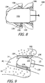
- the hearing assistance device 100 When the hearing assistance device 100 is inserted into the ear canal 10, it will transition from the uncompressed state ( FIG. 8 ) to the compressed state ( FIG. 9 ) where the medial seal 104 is compressed. As a result, a portion of the gel 108 will flow through the opening 160 and into the previously open space defined by the opening 106, outer surface 148 of the lateral seal 106 and the surface of the ear canal wall. The gel 108 (or other viscous media), both that remaining within the cavity 158 and that now outside the cavity 158, will promote sound attenuation and vapor transport without increasing pressure on the ear canal wall.
- exemplary viscous media include purely viscous media, viscoelastic media, and gels.
- a purely viscous medium will flow and redistribute as the seal conforms to the canal, thereby occupying space and enhancing overall sound attenuation.
- the purely viscous medium with not add to the restoring force of the seal 104 and the only pressure against the ear canal walls will only be that provided by the elastic spring force of the compressed seal.
- a purely viscous medium may be useful in some implementations because it does not add to the restoring force of the seal and the pressure exerted onto the ear canal wall.
- a purely viscous medium may also flow out of the cavity 158 (depending on the orientation of the hearing assistance device) or diffuse into the foam that forms the seal during storage.
- a viscoelastic medium on the other hand, will provide a restoring force as it is deflected, which will add to the restoring force of the seals as well as providing sound attenuation.
- one exemplary gel is clay/glycerine gel.
- Clays such as, for example, bentonite, smectitie, montmorillonite, hectorite, and synthetic silicate, can swell significantly in aqueous solution or organic polar liquids due to intercalation of liquids into the silicate layers, thereby thickening the solutions into a non-flowable gel.
- a glycerine gel made with 2.25% clay will remain a non-flowable gel at temperatures up to 100°C.
- the deflection force associated with the seal 104 and gel 108 will only be about 5-6% greater than that associated with an otherwise identical seal 104 alone.
- the gel may be produced by the following process: (1) disperse the clay into water to form a water/clay gel, (2) add glycerine to the water/clay gel to form a glycerine/water/clay mixture, and (3) evaporate the water to produce the glycerine/clay gel.
- the glycerine/clay gel can be placed into a syringe (in liquid form) and dispensed in the manner described above.
- Carbopol®/glycerine gel Another exemplary gel is Carbopol®/glycerine gel.
- Carbopol® polyacrylic acid
- TMP trometamol
- proplylene glycol a water based hydrogel with trometamol (tris) and proplylene glycol.
- Its viscosity is pH dependent, and the viscosity decreases when pH decreases.
- the gel may be produced by the following process: (1) mix Carbopol® in water, (2) add glycerine, (3) neutralize, and (4) remove the water to produce the Carbopol®/glycerine gel.
- the Carbopol®/glycerine gel can be placed into a syringe (in liquid form) and dispensed in the manner described above.
- Still another exemplary gel is agar-glycerine gel with an agar concentration of about 1.6% to 1.7%.
- the temperature of the mixture should be about 95°C to 100°C (and not yet gelled) when dispensed into the seal in the manner described above. The mixture will begin to gel when it cools to about 40°C.
- polyvinyl alcohol gel which is a water based hydrogel that may involve the use of a cross-linking agent such as borane (trihydridoboron).
- the viscous medium 108 may be injected or otherwise dispensed into the cavity 158, which is located between the exterior surface of the hearing device core 102 and the shell wall interior surface 150, at any appropriate time.
- the viscous medium 108 may be dispensed into the cavity 158 during the hearing device manufacturing process (prior to packaging and shipping), or at the point of sale, or at the time of fitting.
- the viscous medium 108 is provided separately to the hearing healthcare professional (e.g., in a syringe with a dispensing needle) so that the viscous medium 108 can be dispensed into the cavity 158 just moments prior to fitting or inserting the hearing device into the ear canal.
- a similar process may be employed for those users who are capable of dispensing the viscous medium 108 into the cavity 158 themselves at the time of insertion.
- the size and geometry of the ear canal varies from one person to another and, accordingly, so does the size and geometry of the hearing device 100. Variation in the size and geometry of the hearing device 100 may be accomplished by way of variations in the size and geometry of the medial seal 104 and the lateral seal 106.
- the volume of the cavity 158 between the exterior surface of the hearing device core 102 and the shell wall interior surface 150 will vary from one hearing device to another due to the variations in the size of the medial seal 104, as will the volume of the viscous medium 108 within the cavity 158.
- the geometry of the ear canal also plays a role in the volume of the cavity 158 when the hearing device is located within the bony region.
- the volume of the viscous medium 108 may range from 5 ⁇ l for a medial seal 104 that is appropriate for narrow ear canal (canal medium diameter of 5 mm) to 100 ⁇ l for a medial seal 104 that is appropriate for a large ear canal (canal medium diameter of 10 mm).
- the hearing assistance device 100 may be configured to facilitate receipt of the correct amount of viscous medium 108. For example, a mark (not shown) that indicates when maximum volume has been dispensed into the cavity 158 may be located on the interior surface 150 of the medial seal 104.
- the mark can be added the seal after it is formed, or can be an integrated structure (e.g., a groove or protrusion) that is formed during manufacture of the seal.
- the mark can extend around the entire circumference of seal inner surface 150 (at the location that corresponds to the desired volume) or can be located at one or more discrete locations on the inner surface. Such a mark is useful, whether the viscous material is dispensed during manufacturing, or by the audiologist, or by the user, because exact dosing of a viscous medium can be challenging.
- Certain aspects of the inner surface 150 of the medial seal 104 and/or the outer surface of the core 102 may be initially manufactured, or modified prior to the addition of the viscous medium 108, so as to improve the interaction with the viscous medium.
- the inner surface 150 of the medial seal 104 and/or the outer surface of the core 102 may be manufactured or modified so as to adhere to a particular viscous medium 108.
- Such surface aspects include, but are not limited to, roughness, porosity, hydrophobicity and hydrophilicity, as well as any and all combinations thereof.
Landscapes
- Engineering & Computer Science (AREA)
- Health & Medical Sciences (AREA)
- General Health & Medical Sciences (AREA)
- Neurosurgery (AREA)
- Otolaryngology (AREA)
- Physics & Mathematics (AREA)
- Acoustics & Sound (AREA)
- Signal Processing (AREA)
- Manufacturing & Machinery (AREA)
- Prostheses (AREA)
- Battery Mounting, Suspending (AREA)
Description
- The present inventions relate generally to hearing devices and, for example, hearing devices that are worn entirely in the ear canal for extended periods without daily insertion and removal.
- Referring to the coronal view illustrated in
FIG. 1 , theadult ear canal 10 extends from thecanal aperture 12 to the tympanic membrane (or "eardrum") 14, and includes a lateralcartilaginous region 16 and abony region 18 which are separated by the bony-cartilaginous junction 20.Debris 22 andhair 24 in the ear canal are primarily present in thecartilaginous region 16. Theconcha cavity 26 and auricle 28 are located lateral of theear canal 10, and the junction between theconcha cavity 26 andcartilaginous region 16 of the ear canal at theaperture 12 is also defined by acharacteristic bend 30, which is known as the first bend of the ear canal. - Extended wear hearing devices are configured to be worn continuously, from several weeks to several months, inside the ear canal. Some extended wear hearing devices are configured to rest entirely within the bony region and, in some instances, within 4 mm of the tympanic membrane. Examples of extended wear hearing devices are disclosed in
U.S. Patent Pub. No. 2009/0074220 ,U.S. Patent No. 7,664,282 andU.S. Patent No. 8,682,01 6 . Such hearing devices frequently include one or more seal retainers (or "seals") that suspend and retain the hearing device within the ear canal and also suppress sound transmission and feedback which can occur when there is acoustic leakage between the receiver and microphone. The seals are frequently formed from a highly porous and highly compliant foam material (e.g., hydrophilic polyurethane foam), which conforms to the ear canal geometry by deflection and compression, using a net-shape molding process. The seals tend to be very small, with outer diameters of around 0.5 inch (1.27 cm), and very thin, with wall thicknesses of around 0.02 to 0.03 inch (0.508 to 0.762 mm). -
US 2006/0291682 A1 relates to hearing device according to the preamble of claim 1.US 2009/0320859 A1 relates to a self-fitting ear plug comprising a bladder having an internal chamber and being deformable between an at-rest position and a smaller insertion position. The chamber may be filled with a fluid which is sealed from an environment outside the bladder. Alternatively, and generally, the chamber need not be sealed from the environment.US 6473512 B1 discloses a hearing device comprising a self-fitting ear plug in the form of a sealed bladder that can be filled with a variable amount of viscous material using a valve. -
US 2011/0051979 A1 relates to in-ear-headphones comprising an ear tip which consists of a central bore for receiving a sound conduit of the headphone and which consists of an external layer which surrounds an internal filling which may be a silicone gel. - The present inventors have determined that hearing devices which are configured to be placed deep in the ear canal are susceptible to improvement. For example, there are a variety of important, and sometimes conflicting, functional goals associated with the seals. Although the friction between the seals and the ear canal must be sufficient to prevent lateral migration of the hearing device, the seals must be compliant enough to conform to the ear canal, and the local pressure exerted on the ear canal wall should be less than the venous capillary return pressure of the epithelial tissue layer of the canal wall (i.e., less than about 12 mmHg (1599.87 Pa)). The seals must be durable in that there is no more than minimal degradation or change of structural integrity in response to prolonged contact with sweat, ear wax and soapy water. The seals should also be skin biocompatible. Acoustically, the seals should provide acoustic attenuation in order to prevent feedback (e.g., >40dB between 200 Hz and 6 kHz). The seals should permit venting that allows pressure equalization between the ambient environment and the closed volume near the tympanic membrane, and have a vapor transmission rate sufficient to prevent moisture accumulation in the closed volume (e.g., MVTR > 0.05 mg/h/mm2 at 37°C). The present inventors have further determined that, given their very thin wall thicknesses, it is difficult to reliably manufacture seals that achieve these goals using net-shape molding and other currently available manufacturing techniques for manufacturing foam objects. In particular, reliably achieving good acoustic attenuation often occurs at the expense of compliance and comfort.
- The invention relates to a hearing device as defined in claim 1.
- There are a variety of advantages associated with such a hearing device. By way of example, but not limitation, the viscous medium augments the sound attenuation associated with the seal and promotes vapor transmission without substantially increasing the pressure on the ear canal wall associated with the seal or interfering with pressure equalization.
- The above described and many other features of the present inventions will become apparent as the inventions become better understood by reference to the following detailed description when considered in conjunction with the accompanying drawings.
- Detailed descriptions of the exemplary embodiments will be made with reference to the accompanying drawings.
-
FIG. 1 is a section view showing the anatomical features of the ear and ear canal. -
FIG. 2 is a perspective view of an exemplary hearing device. -
FIG. 3 is a partial section view taken along line 3-3 inFIG. 2 . -
FIG. 4 is an exploded perspective view of the hearing device illustrated inFIGS. 2 and 3 . -
FIG. 5 is a perspective view of a portion of the hearing device illustrated inFIGS. 2 and 3 . -
FIG. 6 is a section view of an exemplary seal. -
FIG. 7 is a partial section view of an exemplary hearing device core and seal. -
FIG. 8 is a partial section view of the hearing device illustrated inFIGS. 2 and 3 . -
FIG. 9 is a partial section view showing the hearing device illustrated inFIGS. 2 and 3 within the ear canal. - The following is a detailed description of the best presently known modes of carrying out the inventions. This description is not to be taken in a limiting sense, but is made merely for the purpose of illustrating the general principles of the inventions. Referring to
FIG. 1 , it should also be noted that as used herein, the term "lateral" refers to the direction and parts of hearing devices which face away from the tympanic membrane, the term "medial" refers to the direction and parts of hearing devices which face toward the tympanic membrane, the term "superior" refers to the direction and parts of hearing devices which face the top of the head, the term "inferior" refers to the direction and parts of hearing devices which face the feet, the term "anterior" refers to the direction and parts of hearing devices which face the front of the body, and the "posterior" refers to the direction and parts of hearing devices which face the rear of the body. - As illustrated in
FIGS. 2 and 3 , anexemplary hearing device 100 includes acore 102, amedial seal 104, alateral seal 106, and a volume ofviscous medium 108 located within a cavity that is located between an exterior surface of the core and an interior surface of themedial seal 104. The viscous medium may be, for example, a purely viscous medium, a viscoelastic medium, or a gelled viscous medium. Briefly, when thehearing device 100 is inserted into the ear canal, the viscous medium will occupy the cavity as well as some of the open space between the hearing assistance device and the ear canal. The viscous medium promotes sound attenuation and humidity transport without substantially increasing (i.e., without increasing by more than 50%) the seal pressure on the ear canal wall. In some implementations, the addition of theviscous medium 108 increases the acoustic attenuation of theseal 104 by 3dB or more. Put in another way, in some implementations, the acoustic attenuation caused by the combinedseal 104 andviscous medium 108 is at least 3dB greater than the acoustic attenuation caused by an otherwiseidentical seal 104 without theviscous medium 108. Thecore 102,seals viscous medium 108 of theexemplary hearing device 100 are each discussed in greater detail below. - Referring first to
FIGS. 4 and 5 , and although the present inventions are not limited to any particular core, theexemplary core 102 includes anacoustic assembly 110 and a battery 112 (e.g., metal-air battery) located within ahousing 114. Theacoustic assembly 110 has amicrophone 116, areceiver 118 and aflexible circuit 120. Thereceiver 118 has asound port 119 that is associated with anaperture 121 on thehousing 114. The exemplaryflexible circuit 120 includes an integrated circuit oramplifier 122 and otherdiscreet components 124 on aflexible substrate 126. Theexemplary battery 112 has acathode assembly 128 and ananode assembly 130. Theexemplary cathode assembly 128 includes a battery can cathodeportion 132 and an air cathode (not shown), and theexemplary anode assembly 130 includes a battery can anodeportion 134 and anode material (not shown). Thecathode assembly 128 andanode assembly 130 may initially be separate, individually formed structural elements that are joined to one another during the manufacturing process. Theexemplary battery 112 is electrically connected to theflexible circuit 120 by way of anode andcathode wires contamination guard 140 with a screen (not shown) abuts the microphone. Ahandle 142 may also be provided. It should be noted that in other implementations, thehousing 114 may be omitted and theacoustic assembly 110, or theacoustic assembly 110 and thebattery 112, or the acoustic assembly alone, may be encased by an encapsulant. Additional details concerning the present hearing assistance device cores may be found inU.S. Pat. No. 8,761,423 . - Turning to
FIGS. 6 and 7 , and as noted above, theexemplary seals core 102 within the ear canal bony portion and are configured to substantially conform to the shape of walls of the ear canal, maintain an acoustical seal between a seal surface and the ear canal, and retain thehearing device 100 securely within the ear canal. The medial andlateral seals medial seal 104 in the interest of brevity. Additional information concerning the specifics of exemplary seal apparatus may be found inU.S. Patent No. 7,580,537 . Themedial seal 104 includes ashell wall 146 with an outwardly facingexterior surface 148, an inwardly facinginterior surface 150, abase portion 152 and an outwardly bowedportion 154. Thebase portion 152 includes anopening 156 that is sized and shaped for mounting on thehearing device core 102. Theopening 156 may be centrally placed or offset with respect to theshell wall 146, and may be oval, substantially circular or square. The outwardly bowedportion 154 is sized and shaped such that it will be spaced apart from the outer surface of thehearing device core 102. Acavity 158, which has anopening 160 located at the end of the outwardly bowedportion 154, is defined between the exterior surface of thehearing device core 102 and the shell wallinterior surface 150. In the illustrated embodiment, theinterior surface 150 includes a plurality ofscallops 162 that may be used to impart the desired level of stiffness and conformability to theshell wall 146. Theseals core 102 with adhesive. - With respect to materials, the
seals hearing assistance device 100 in place in the ear canal. Exemplary foams, both open cell and closed cell, include but are not limited to foams formed from polyurethanes, silicones, polyethylenes, fluoropolymers and copolymers thereof. Hydrophilic polyurethane foam is one specific example. In at least some embodiments, all or a portion of the seals can comprise a hydrophobic material including a hydrophobic layer or coating that is also permeable to water vapor transmission. Examples of such materials include, but are not limited to, silicones and fluoropolymers such as expanded polytetrafluoroethylene (PTFE). - Turning to the
viscous medium 108, the viscous medium employed will preferably enhance sound attenuation without significantly increasing the stiffness of the associated seal (e.g., seal 104). Exemplary viscous media include, but are not limited to, purely viscous media such as glycerol, petroleum jelly and wax, viscoelastic media such as a rubber, and gelled viscous media (or "gel"). The properties of the gels and other viscous media, which are preferably hygroscopic, provide sufficient moisture transport to promote ear health. - The
viscous medium 108 in the illustrated embodiment is a gel. Various examples of gelled viscous media, and the benefits associated therewith, are provided below. The gels may have relatively weak cross-linking between the polymer chains. This results in a structural coherence that is sufficient to prevent the gel from flowing out of thecavity 158, regardless of the orientation of the hearing assistance device, or diffusing into the seal foam during storage at room temperature or usage at body temperature, and also results in a modulus that is low enough to preclude substantial reductions in the compliance of the seal that would increase pressure on the ear canal wall. During manufacture, thehearing assistance device 100 may be oriented such that the medial end faces downwardly and the gel may be injected into thecavity 158 in a liquid state with a syringe or other suitable dispenser. The liquid will be allowed to cure and form thegel 108 that occupies most (or all) of thecavity 158 and is mechanically interlocked with the foam of theseal 104. Because thecavity 158 has anopening 160, and because the gel (or other viscous medium in other embodiments) is not located with a bag, balloon, bladder or other enclosed structure, the gel is free to flow out of the cavity when theseal 104 is compressed. The same manufacturing technique may be employed in conjunction with purely viscous and viscoelastic media. - When the
hearing assistance device 100 is inserted into theear canal 10, it will transition from the uncompressed state (FIG. 8 ) to the compressed state (FIG. 9 ) where themedial seal 104 is compressed. As a result, a portion of thegel 108 will flow through theopening 160 and into the previously open space defined by theopening 106,outer surface 148 of thelateral seal 106 and the surface of the ear canal wall. The gel 108 (or other viscous media), both that remaining within thecavity 158 and that now outside thecavity 158, will promote sound attenuation and vapor transport without increasing pressure on the ear canal wall. - As noted above, exemplary viscous media include purely viscous media, viscoelastic media, and gels. A purely viscous medium will flow and redistribute as the seal conforms to the canal, thereby occupying space and enhancing overall sound attenuation. The purely viscous medium with not add to the restoring force of the
seal 104 and the only pressure against the ear canal walls will only be that provided by the elastic spring force of the compressed seal. The present inventors have determined although that purely viscous media may not flow evenly through theopening 160 and out of thecavity 158 when theseal 104 is pressed into the ear canal and compressed, a purely viscous medium may be useful in some implementations because it does not add to the restoring force of the seal and the pressure exerted onto the ear canal wall. A purely viscous medium may also flow out of the cavity 158 (depending on the orientation of the hearing assistance device) or diffuse into the foam that forms the seal during storage. A viscoelastic medium, on the other hand, will provide a restoring force as it is deflected, which will add to the restoring force of the seals as well as providing sound attenuation. Care must be taken to insure that the total restoring force is less than the venous capillary return pressure of the epithelial tissue layer. Nevertheless, it should be emphasized that, like the purely viscous media, viscoelastic media may be employed as desired or required by particular implementations. - With respect to gels, one exemplary gel is clay/glycerine gel. Clays such as, for example, bentonite, smectitie, montmorillonite, hectorite, and synthetic silicate, can swell significantly in aqueous solution or organic polar liquids due to intercalation of liquids into the silicate layers, thereby thickening the solutions into a non-flowable gel. For example, a glycerine gel made with 2.25% clay will remain a non-flowable gel at temperatures up to 100°C. The deflection force associated with the
seal 104 andgel 108 will only be about 5-6% greater than that associated with an otherwiseidentical seal 104 alone. The gel may be produced by the following process: (1) disperse the clay into water to form a water/clay gel, (2) add glycerine to the water/clay gel to form a glycerine/water/clay mixture, and (3) evaporate the water to produce the glycerine/clay gel. The glycerine/clay gel can be placed into a syringe (in liquid form) and dispensed in the manner described above. - Another exemplary gel is Carbopol®/glycerine gel. Carbopol® (polyacrylic acid) leads to a water based hydrogel with trometamol (tris) and proplylene glycol. Its viscosity is pH dependent, and the viscosity decreases when pH decreases. Directly mixing Carbopol® into glycerine, followed by neutralization, significantly increases the viscosity of the glycerine. While the viscosity without Carbopol® is about 1150cp (1.15 Pa.s), the viscosity increases to about 26500cp (26.5 Pa.s) with 0.4% Carbopol®. Higher amounts of Carbopol® can be dispersed into glycerine for higher viscosities. The gel may be produced by the following process: (1) mix Carbopol® in water, (2) add glycerine, (3) neutralize, and (4) remove the water to produce the Carbopol®/glycerine gel. The Carbopol®/glycerine gel can be placed into a syringe (in liquid form) and dispensed in the manner described above.
- Still another exemplary gel is agar-glycerine gel with an agar concentration of about 1.6% to 1.7%. Here, the temperature of the mixture should be about 95°C to 100°C (and not yet gelled) when dispensed into the seal in the manner described above. The mixture will begin to gel when it cools to about 40°C.
- Yet another exemplary gel is polyvinyl alcohol gel, which is a water based hydrogel that may involve the use of a cross-linking agent such as borane (trihydridoboron).
- It should be noted here that the
viscous medium 108 may be injected or otherwise dispensed into thecavity 158, which is located between the exterior surface of thehearing device core 102 and the shell wallinterior surface 150, at any appropriate time. For example, theviscous medium 108 may be dispensed into thecavity 158 during the hearing device manufacturing process (prior to packaging and shipping), or at the point of sale, or at the time of fitting. In the case of fitting, theviscous medium 108 is provided separately to the hearing healthcare professional (e.g., in a syringe with a dispensing needle) so that theviscous medium 108 can be dispensed into thecavity 158 just moments prior to fitting or inserting the hearing device into the ear canal. A similar process may be employed for those users who are capable of dispensing theviscous medium 108 into thecavity 158 themselves at the time of insertion. - The size and geometry of the ear canal varies from one person to another and, accordingly, so does the size and geometry of the
hearing device 100. Variation in the size and geometry of thehearing device 100 may be accomplished by way of variations in the size and geometry of themedial seal 104 and thelateral seal 106. The volume of thecavity 158 between the exterior surface of thehearing device core 102 and the shell wallinterior surface 150 will vary from one hearing device to another due to the variations in the size of themedial seal 104, as will the volume of theviscous medium 108 within thecavity 158. The geometry of the ear canal also plays a role in the volume of thecavity 158 when the hearing device is located within the bony region. In those instances where the medium diameter of the hearing device core is about 4 mm, the volume of theviscous medium 108 may range from 5 µl for amedial seal 104 that is appropriate for narrow ear canal (canal medium diameter of 5 mm) to 100 µl for amedial seal 104 that is appropriate for a large ear canal (canal medium diameter of 10 mm). - If the quantity of viscous medium 108 that is dispensed into the
cavity 158 is too low, then the acoustic attenuation may not meet the desired level. If, on the other hand, the quantity is too high, theviscous medium 108 may leak out of thecavity 158 in an uncontrolled manner and, possibly, block themicrophone contamination guard 140 or cause other undesirable effects. As such, in at least some implementations, thehearing assistance device 100 may be configured to facilitate receipt of the correct amount ofviscous medium 108. For example, a mark (not shown) that indicates when maximum volume has been dispensed into thecavity 158 may be located on theinterior surface 150 of themedial seal 104. The mark can be added the seal after it is formed, or can be an integrated structure (e.g., a groove or protrusion) that is formed during manufacture of the seal. The mark can extend around the entire circumference of seal inner surface 150 (at the location that corresponds to the desired volume) or can be located at one or more discrete locations on the inner surface. Such a mark is useful, whether the viscous material is dispensed during manufacturing, or by the audiologist, or by the user, because exact dosing of a viscous medium can be challenging. - Certain aspects of the
inner surface 150 of themedial seal 104 and/or the outer surface of thecore 102 may be initially manufactured, or modified prior to the addition of theviscous medium 108, so as to improve the interaction with the viscous medium. For example, theinner surface 150 of themedial seal 104 and/or the outer surface of thecore 102 may be manufactured or modified so as to adhere to a particularviscous medium 108. Such surface aspects include, but are not limited to, roughness, porosity, hydrophobicity and hydrophilicity, as well as any and all combinations thereof. - Although the inventions disclosed herein have been described in terms of the preferred embodiments above, numerous modifications and/or additions to the above-described preferred embodiments would be readily apparent to one skilled in the art, within the scope defined by the appended claims. By way of example, but not limitation, the inventions include any combination of the elements from the various species and embodiments disclosed in the specification that are not already described. It is intended that the scope of the present inventions extend to all such modifications and/or additions and that the scope of the present inventions is limited solely by the claims set forth below.
Claims (11)
- A hearing device, comprising:a hearing device core (102) defining an exterior surface and including a battery (112), a microphone (116) and a receiver (118); anda seal (104), including a shell wall (146) and defining an outwardly facing exterior surface (148), an inwardly facing interior surface (150), a first end and a second end, mounted on the hearing device core (102) with the shell wall first end secured to the hearing device core (102), the shell wall second end located in spaced relation to the hearing device core (102), and a cavity (158) that has an opening (160) located at the shell wall second end defined between the hearing device core exterior surface and the shell wall interior surface (150); wherein the hearing device is an extended wear hearing device configured to be worn entirely in the ear canal,characterized bya volume of viscous medium (108) located within the cavity (158) between the hearing device core exterior surface and the shell wall interior surface (150).
- The hearing device of claim 1, wherein
the seal (104) is movable between an uncompressed state and a compressed state;
the hearing device core (102) defines lateral and medial ends and the shell wall second end is located between the lateral and medial ends of the hearing device core;
the cavity (158) defines a first cavity volume when the seal is in the uncompressed state and a second cavity volume, that is less than the first cavity volume, when the seal is in the compressed state; and
the volume of viscous medium (108) is equal to or less than the first cavity volume. - The hearing device of claim 2, wherein
the volume of viscous medium (108) within the cavity (158) between the hearing device core exterior surface and the shell wall interior surface (150) is the only viscous medium associated with the hearing device (100). - The hearing device of claim 2, configured such that movement of the seal (104) from the uncompressed state to the compressed state forces a portion of the volume of viscous medium through the cavity opening (160).
- The hearing device of claim 4, wherein
the seal comprises a medial seal (104) that is oriented such that the first end defines the medial end and the second end defines the lateral end;
the hearing device (100) further comprises a lateral seal (106), including an outwardly facing exterior surface, mounted on the hearing device core (102) such that there is a space that extends from the cavity opening (160) to the lateral seal exterior surface; and
the portion of the volume of viscous medium (108) that is forced through the cavity opening is forced into the space that extends from the cavity opening to the lateral seal exterior surface. - The hearing device of claim 1, wherein
the hearing device core (102) defines a longitudinal axis and the hearing device core exterior surface (148) defines a perimeter that extends around the longitudinal axis;
the cavity (158) extends around the entire perimeter of the hearing device core exterior surface; and
the cavity opening (160) extends around the entire perimeter of the hearing device core exterior surface. - The hearing device of claim 1, wherein
shell wall interior surface (150) includes a plurality of scallops (162). - The hearing device of claim 1, wherein
the shell wall (146) is formed from elastomeric foam. - The hearing device of claims 1 to 8, wherein
the viscous medium (108) comprise a gel. - The hearing device of claim 9, wherein
the gel is selected from the group consisting of clay/glycerin gel, carbopol/glycerin gel, agar/glycerin gel and polyvinyl alcohol gel. - The hearing device of claim 9, wherein
the gel is selected from the group consisting of viscous gel and viscoelastic gel.
Applications Claiming Priority (1)
| Application Number | Priority Date | Filing Date | Title |
|---|---|---|---|
| PCT/US2015/019519 WO2016144319A1 (en) | 2015-03-09 | 2015-03-09 | Canal hearing devices with improved seals |
Publications (2)
| Publication Number | Publication Date |
|---|---|
| EP3269153A1 EP3269153A1 (en) | 2018-01-17 |
| EP3269153B1 true EP3269153B1 (en) | 2019-05-22 |
Family
ID=52706298
Family Applications (1)
| Application Number | Title | Priority Date | Filing Date |
|---|---|---|---|
| EP15711620.3A Active EP3269153B1 (en) | 2015-03-09 | 2015-03-09 | Canal hearing devices with improved seals |
Country Status (4)
| Country | Link |
|---|---|
| US (1) | US10237665B2 (en) |
| EP (1) | EP3269153B1 (en) |
| DK (1) | DK3269153T3 (en) |
| WO (1) | WO2016144319A1 (en) |
Families Citing this family (4)
| Publication number | Priority date | Publication date | Assignee | Title |
|---|---|---|---|---|
| US11206499B2 (en) | 2016-08-18 | 2021-12-21 | Qualcomm Incorporated | Hearable device comprising integrated device and wireless functionality |
| WO2019070713A1 (en) * | 2017-10-03 | 2019-04-11 | W. L. Gore & Associates, Inc. | Acoustic ear fitting |
| CN108784731A (en) * | 2018-04-28 | 2018-11-13 | 李振 | A kind of medical high adjustable stethoscope of pickup |
| EP3726855B1 (en) * | 2019-04-15 | 2021-09-01 | Sonion Nederland B.V. | A personal hearing device with a vent channel and acoustic separation |
Citations (2)
| Publication number | Priority date | Publication date | Assignee | Title |
|---|---|---|---|---|
| US6473512B1 (en) * | 1997-12-18 | 2002-10-29 | Softear Technologies, L.L.C. | Apparatus and method for a custom soft-solid hearing aid |
| US20110051979A1 (en) * | 2009-09-03 | 2011-03-03 | Monster Cable Products, Inc. | Headphone Ear Tips with Sound Conduit Mounting Structure |
Family Cites Families (12)
| Publication number | Priority date | Publication date | Assignee | Title |
|---|---|---|---|---|
| US20060291683A1 (en) * | 1998-11-25 | 2006-12-28 | Insound Medical, Inc. | Sealing retainer for extended wear hearing devices |
| US7664282B2 (en) | 1998-11-25 | 2010-02-16 | Insound Medical, Inc. | Sealing retainer for extended wear hearing devices |
| US7580537B2 (en) * | 1998-11-25 | 2009-08-25 | Insound Medical, Inc. | Sealing retainer for extended wear hearing devices |
| US6359993B2 (en) | 1999-01-15 | 2002-03-19 | Sonic Innovations | Conformal tip for a hearing aid with integrated vent and retrieval cord |
| US7684580B2 (en) * | 2005-11-28 | 2010-03-23 | Phonak Ag | Hearing device to be at least partially inserted into an ear canal |
| US7779844B2 (en) | 2006-12-15 | 2010-08-24 | Kimberly-Clark Worldwide, Inc. | Self-fitting device for location in an ear canal |
| US9071914B2 (en) | 2007-08-14 | 2015-06-30 | Insound Medical, Inc. | Combined microphone and receiver assembly for extended wear canal hearing devices |
| US7913696B2 (en) * | 2008-06-30 | 2011-03-29 | Kimberly-Clark Worldwide Inc. | Self-fitting device for location in an ear canal |
| US8808906B2 (en) * | 2011-11-23 | 2014-08-19 | Insound Medical, Inc. | Canal hearing devices and batteries for use with same |
| US8761423B2 (en) | 2011-11-23 | 2014-06-24 | Insound Medical, Inc. | Canal hearing devices and batteries for use with same |
| US8682016B2 (en) | 2011-11-23 | 2014-03-25 | Insound Medical, Inc. | Canal hearing devices and batteries for use with same |
| EP2896220B1 (en) * | 2012-09-17 | 2016-12-28 | Sonova AG | Cic hearing aid seal and method of manufacturing the same |
-
2015
- 2015-03-09 US US15/554,656 patent/US10237665B2/en not_active Expired - Fee Related
- 2015-03-09 EP EP15711620.3A patent/EP3269153B1/en active Active
- 2015-03-09 DK DK15711620.3T patent/DK3269153T3/en active
- 2015-03-09 WO PCT/US2015/019519 patent/WO2016144319A1/en not_active Ceased
Patent Citations (2)
| Publication number | Priority date | Publication date | Assignee | Title |
|---|---|---|---|---|
| US6473512B1 (en) * | 1997-12-18 | 2002-10-29 | Softear Technologies, L.L.C. | Apparatus and method for a custom soft-solid hearing aid |
| US20110051979A1 (en) * | 2009-09-03 | 2011-03-03 | Monster Cable Products, Inc. | Headphone Ear Tips with Sound Conduit Mounting Structure |
Also Published As
| Publication number | Publication date |
|---|---|
| DK3269153T3 (en) | 2019-07-15 |
| EP3269153A1 (en) | 2018-01-17 |
| US20180041852A1 (en) | 2018-02-08 |
| US10237665B2 (en) | 2019-03-19 |
| WO2016144319A1 (en) | 2016-09-15 |
Similar Documents
| Publication | Publication Date | Title |
|---|---|---|
| US7580537B2 (en) | Sealing retainer for extended wear hearing devices | |
| US7664282B2 (en) | Sealing retainer for extended wear hearing devices | |
| CN110249636B (en) | Earpieces, methods of making earpieces, and methods of using earpieces | |
| RU2325889C2 (en) | Earplug and method of production | |
| CN102481207B (en) | Improved earplugs | |
| US10237665B2 (en) | Canal hearing devices with improved seals | |
| US20060291683A1 (en) | Sealing retainer for extended wear hearing devices | |
| US20110268308A1 (en) | Partially Occluding Ergonomic Earbud Adapter | |
| US9521495B2 (en) | CIC hearing aid seal and method of manufacturing the same | |
| CN111670582B (en) | earpiece | |
| US7934916B2 (en) | Custom earpiece | |
| US11986375B2 (en) | Inflatable earplug system | |
| CN201797582U (en) | Equipment shell used as earplug case of in-ear earphone and electronic equipment protective cover | |
| US11277698B2 (en) | Canal hearing devices with improved seals | |
| CN216930266U (en) | UV rubber earphone plug | |
| CN210351540U (en) | Earplug cover of in-ear earphone | |
| JP2986708B2 (en) | Earpiece | |
| JP2002199495A (en) | Earplug | |
| JP2612920B2 (en) | Earpiece | |
| AU2010219362A1 (en) | Improved eartip | |
| CN210249862U (en) | Earplug for external auditory canal CT scanning and positioning | |
| CN115297396A (en) | Shallow in-ear earphone silica gel cap and earphone of many scenes | |
| HK40006895A (en) | Earpiece intra-auricular support system | |
| HK40006895B (en) | Earpiece, method of making an earpiece, and method of using an earpiece | |
| CN104703084A (en) | Earphone plug |
Legal Events
| Date | Code | Title | Description |
|---|---|---|---|
| STAA | Information on the status of an ep patent application or granted ep patent |
Free format text: STATUS: THE INTERNATIONAL PUBLICATION HAS BEEN MADE |
|
| PUAI | Public reference made under article 153(3) epc to a published international application that has entered the european phase |
Free format text: ORIGINAL CODE: 0009012 |
|
| STAA | Information on the status of an ep patent application or granted ep patent |
Free format text: STATUS: REQUEST FOR EXAMINATION WAS MADE |
|
| 17P | Request for examination filed |
Effective date: 20170913 |
|
| AK | Designated contracting states |
Kind code of ref document: A1 Designated state(s): AL AT BE BG CH CY CZ DE DK EE ES FI FR GB GR HR HU IE IS IT LI LT LU LV MC MK MT NL NO PL PT RO RS SE SI SK SM TR |
|
| AX | Request for extension of the european patent |
Extension state: BA ME |
|
| RIN1 | Information on inventor provided before grant (corrected) |
Inventor name: GUNDE, PETRA Inventor name: LIN, CHUANGGANG Inventor name: WAGNER, PAUL Inventor name: KARAMUK, ERDAL Inventor name: KELLER, SIMONE Inventor name: AU, MICHAEL |
|
| DAV | Request for validation of the european patent (deleted) | ||
| DAX | Request for extension of the european patent (deleted) | ||
| STAA | Information on the status of an ep patent application or granted ep patent |
Free format text: STATUS: EXAMINATION IS IN PROGRESS |
|
| 17Q | First examination report despatched |
Effective date: 20180703 |
|
| GRAP | Despatch of communication of intention to grant a patent |
Free format text: ORIGINAL CODE: EPIDOSNIGR1 |
|
| STAA | Information on the status of an ep patent application or granted ep patent |
Free format text: STATUS: GRANT OF PATENT IS INTENDED |
|
| INTG | Intention to grant announced |
Effective date: 20181218 |
|
| GRAS | Grant fee paid |
Free format text: ORIGINAL CODE: EPIDOSNIGR3 |
|
| GRAA | (expected) grant |
Free format text: ORIGINAL CODE: 0009210 |
|
| STAA | Information on the status of an ep patent application or granted ep patent |
Free format text: STATUS: THE PATENT HAS BEEN GRANTED |
|
| AK | Designated contracting states |
Kind code of ref document: B1 Designated state(s): AL AT BE BG CH CY CZ DE DK EE ES FI FR GB GR HR HU IE IS IT LI LT LU LV MC MK MT NL NO PL PT RO RS SE SI SK SM TR |
|
| REG | Reference to a national code |
Ref country code: GB Ref legal event code: FG4D |
|
| REG | Reference to a national code |
Ref country code: CH Ref legal event code: EP |
|
| REG | Reference to a national code |
Ref country code: IE Ref legal event code: FG4D |
|
| REG | Reference to a national code |
Ref country code: DE Ref legal event code: R096 Ref document number: 602015030732 Country of ref document: DE |
|
| REG | Reference to a national code |
Ref country code: AT Ref legal event code: REF Ref document number: 1137553 Country of ref document: AT Kind code of ref document: T Effective date: 20190615 |
|
| REG | Reference to a national code |
Ref country code: DK Ref legal event code: T3 Effective date: 20190708 |
|
| REG | Reference to a national code |
Ref country code: NL Ref legal event code: MP Effective date: 20190522 |
|
| REG | Reference to a national code |
Ref country code: LT Ref legal event code: MG4D |
|
| PG25 | Lapsed in a contracting state [announced via postgrant information from national office to epo] |
Ref country code: ES Free format text: LAPSE BECAUSE OF FAILURE TO SUBMIT A TRANSLATION OF THE DESCRIPTION OR TO PAY THE FEE WITHIN THE PRESCRIBED TIME-LIMIT Effective date: 20190522 Ref country code: PT Free format text: LAPSE BECAUSE OF FAILURE TO SUBMIT A TRANSLATION OF THE DESCRIPTION OR TO PAY THE FEE WITHIN THE PRESCRIBED TIME-LIMIT Effective date: 20190922 Ref country code: LT Free format text: LAPSE BECAUSE OF FAILURE TO SUBMIT A TRANSLATION OF THE DESCRIPTION OR TO PAY THE FEE WITHIN THE PRESCRIBED TIME-LIMIT Effective date: 20190522 Ref country code: NL Free format text: LAPSE BECAUSE OF FAILURE TO SUBMIT A TRANSLATION OF THE DESCRIPTION OR TO PAY THE FEE WITHIN THE PRESCRIBED TIME-LIMIT Effective date: 20190522 Ref country code: FI Free format text: LAPSE BECAUSE OF FAILURE TO SUBMIT A TRANSLATION OF THE DESCRIPTION OR TO PAY THE FEE WITHIN THE PRESCRIBED TIME-LIMIT Effective date: 20190522 Ref country code: NO Free format text: LAPSE BECAUSE OF FAILURE TO SUBMIT A TRANSLATION OF THE DESCRIPTION OR TO PAY THE FEE WITHIN THE PRESCRIBED TIME-LIMIT Effective date: 20190822 Ref country code: HR Free format text: LAPSE BECAUSE OF FAILURE TO SUBMIT A TRANSLATION OF THE DESCRIPTION OR TO PAY THE FEE WITHIN THE PRESCRIBED TIME-LIMIT Effective date: 20190522 Ref country code: SE Free format text: LAPSE BECAUSE OF FAILURE TO SUBMIT A TRANSLATION OF THE DESCRIPTION OR TO PAY THE FEE WITHIN THE PRESCRIBED TIME-LIMIT Effective date: 20190522 Ref country code: AL Free format text: LAPSE BECAUSE OF FAILURE TO SUBMIT A TRANSLATION OF THE DESCRIPTION OR TO PAY THE FEE WITHIN THE PRESCRIBED TIME-LIMIT Effective date: 20190522 |
|
| PG25 | Lapsed in a contracting state [announced via postgrant information from national office to epo] |
Ref country code: RS Free format text: LAPSE BECAUSE OF FAILURE TO SUBMIT A TRANSLATION OF THE DESCRIPTION OR TO PAY THE FEE WITHIN THE PRESCRIBED TIME-LIMIT Effective date: 20190522 Ref country code: LV Free format text: LAPSE BECAUSE OF FAILURE TO SUBMIT A TRANSLATION OF THE DESCRIPTION OR TO PAY THE FEE WITHIN THE PRESCRIBED TIME-LIMIT Effective date: 20190522 Ref country code: GR Free format text: LAPSE BECAUSE OF FAILURE TO SUBMIT A TRANSLATION OF THE DESCRIPTION OR TO PAY THE FEE WITHIN THE PRESCRIBED TIME-LIMIT Effective date: 20190823 Ref country code: BG Free format text: LAPSE BECAUSE OF FAILURE TO SUBMIT A TRANSLATION OF THE DESCRIPTION OR TO PAY THE FEE WITHIN THE PRESCRIBED TIME-LIMIT Effective date: 20190822 |
|
| REG | Reference to a national code |
Ref country code: AT Ref legal event code: MK05 Ref document number: 1137553 Country of ref document: AT Kind code of ref document: T Effective date: 20190522 |
|
| PG25 | Lapsed in a contracting state [announced via postgrant information from national office to epo] |
Ref country code: AT Free format text: LAPSE BECAUSE OF FAILURE TO SUBMIT A TRANSLATION OF THE DESCRIPTION OR TO PAY THE FEE WITHIN THE PRESCRIBED TIME-LIMIT Effective date: 20190522 Ref country code: RO Free format text: LAPSE BECAUSE OF FAILURE TO SUBMIT A TRANSLATION OF THE DESCRIPTION OR TO PAY THE FEE WITHIN THE PRESCRIBED TIME-LIMIT Effective date: 20190522 Ref country code: CZ Free format text: LAPSE BECAUSE OF FAILURE TO SUBMIT A TRANSLATION OF THE DESCRIPTION OR TO PAY THE FEE WITHIN THE PRESCRIBED TIME-LIMIT Effective date: 20190522 Ref country code: SK Free format text: LAPSE BECAUSE OF FAILURE TO SUBMIT A TRANSLATION OF THE DESCRIPTION OR TO PAY THE FEE WITHIN THE PRESCRIBED TIME-LIMIT Effective date: 20190522 Ref country code: EE Free format text: LAPSE BECAUSE OF FAILURE TO SUBMIT A TRANSLATION OF THE DESCRIPTION OR TO PAY THE FEE WITHIN THE PRESCRIBED TIME-LIMIT Effective date: 20190522 |
|
| REG | Reference to a national code |
Ref country code: DE Ref legal event code: R097 Ref document number: 602015030732 Country of ref document: DE |
|
| PG25 | Lapsed in a contracting state [announced via postgrant information from national office to epo] |
Ref country code: SM Free format text: LAPSE BECAUSE OF FAILURE TO SUBMIT A TRANSLATION OF THE DESCRIPTION OR TO PAY THE FEE WITHIN THE PRESCRIBED TIME-LIMIT Effective date: 20190522 Ref country code: IT Free format text: LAPSE BECAUSE OF FAILURE TO SUBMIT A TRANSLATION OF THE DESCRIPTION OR TO PAY THE FEE WITHIN THE PRESCRIBED TIME-LIMIT Effective date: 20190522 |
|
| PLBE | No opposition filed within time limit |
Free format text: ORIGINAL CODE: 0009261 |
|
| STAA | Information on the status of an ep patent application or granted ep patent |
Free format text: STATUS: NO OPPOSITION FILED WITHIN TIME LIMIT |
|
| PG25 | Lapsed in a contracting state [announced via postgrant information from national office to epo] |
Ref country code: TR Free format text: LAPSE BECAUSE OF FAILURE TO SUBMIT A TRANSLATION OF THE DESCRIPTION OR TO PAY THE FEE WITHIN THE PRESCRIBED TIME-LIMIT Effective date: 20190522 |
|
| 26N | No opposition filed |
Effective date: 20200225 |
|
| PG25 | Lapsed in a contracting state [announced via postgrant information from national office to epo] |
Ref country code: PL Free format text: LAPSE BECAUSE OF FAILURE TO SUBMIT A TRANSLATION OF THE DESCRIPTION OR TO PAY THE FEE WITHIN THE PRESCRIBED TIME-LIMIT Effective date: 20190522 |
|
| PG25 | Lapsed in a contracting state [announced via postgrant information from national office to epo] |
Ref country code: SI Free format text: LAPSE BECAUSE OF FAILURE TO SUBMIT A TRANSLATION OF THE DESCRIPTION OR TO PAY THE FEE WITHIN THE PRESCRIBED TIME-LIMIT Effective date: 20190522 |
|
| PG25 | Lapsed in a contracting state [announced via postgrant information from national office to epo] |
Ref country code: MC Free format text: LAPSE BECAUSE OF FAILURE TO SUBMIT A TRANSLATION OF THE DESCRIPTION OR TO PAY THE FEE WITHIN THE PRESCRIBED TIME-LIMIT Effective date: 20190522 |
|
| REG | Reference to a national code |
Ref country code: CH Ref legal event code: PL |
|
| REG | Reference to a national code |
Ref country code: BE Ref legal event code: MM Effective date: 20200331 |
|
| PG25 | Lapsed in a contracting state [announced via postgrant information from national office to epo] |
Ref country code: LU Free format text: LAPSE BECAUSE OF NON-PAYMENT OF DUE FEES Effective date: 20200309 |
|
| PG25 | Lapsed in a contracting state [announced via postgrant information from national office to epo] |
Ref country code: IE Free format text: LAPSE BECAUSE OF NON-PAYMENT OF DUE FEES Effective date: 20200309 Ref country code: CH Free format text: LAPSE BECAUSE OF NON-PAYMENT OF DUE FEES Effective date: 20200331 Ref country code: LI Free format text: LAPSE BECAUSE OF NON-PAYMENT OF DUE FEES Effective date: 20200331 |
|
| PG25 | Lapsed in a contracting state [announced via postgrant information from national office to epo] |
Ref country code: BE Free format text: LAPSE BECAUSE OF NON-PAYMENT OF DUE FEES Effective date: 20200331 |
|
| PGFP | Annual fee paid to national office [announced via postgrant information from national office to epo] |
Ref country code: GB Payment date: 20220328 Year of fee payment: 8 Ref country code: DK Payment date: 20220329 Year of fee payment: 8 Ref country code: DE Payment date: 20220329 Year of fee payment: 8 |
|
| PG25 | Lapsed in a contracting state [announced via postgrant information from national office to epo] |
Ref country code: MT Free format text: LAPSE BECAUSE OF FAILURE TO SUBMIT A TRANSLATION OF THE DESCRIPTION OR TO PAY THE FEE WITHIN THE PRESCRIBED TIME-LIMIT Effective date: 20190522 Ref country code: CY Free format text: LAPSE BECAUSE OF FAILURE TO SUBMIT A TRANSLATION OF THE DESCRIPTION OR TO PAY THE FEE WITHIN THE PRESCRIBED TIME-LIMIT Effective date: 20190522 |
|
| PGFP | Annual fee paid to national office [announced via postgrant information from national office to epo] |
Ref country code: FR Payment date: 20220325 Year of fee payment: 8 |
|
| PG25 | Lapsed in a contracting state [announced via postgrant information from national office to epo] |
Ref country code: MK Free format text: LAPSE BECAUSE OF FAILURE TO SUBMIT A TRANSLATION OF THE DESCRIPTION OR TO PAY THE FEE WITHIN THE PRESCRIBED TIME-LIMIT Effective date: 20190522 Ref country code: IS Free format text: LAPSE BECAUSE OF FAILURE TO SUBMIT A TRANSLATION OF THE DESCRIPTION OR TO PAY THE FEE WITHIN THE PRESCRIBED TIME-LIMIT Effective date: 20190922 |
|
| REG | Reference to a national code |
Ref country code: DE Ref legal event code: R119 Ref document number: 602015030732 Country of ref document: DE |
|
| REG | Reference to a national code |
Ref country code: DK Ref legal event code: EBP Effective date: 20230331 |
|
| GBPC | Gb: european patent ceased through non-payment of renewal fee |
Effective date: 20230309 |
|
| PG25 | Lapsed in a contracting state [announced via postgrant information from national office to epo] |
Ref country code: GB Free format text: LAPSE BECAUSE OF NON-PAYMENT OF DUE FEES Effective date: 20230309 |
|
| PG25 | Lapsed in a contracting state [announced via postgrant information from national office to epo] |
Ref country code: GB Free format text: LAPSE BECAUSE OF NON-PAYMENT OF DUE FEES Effective date: 20230309 Ref country code: FR Free format text: LAPSE BECAUSE OF NON-PAYMENT OF DUE FEES Effective date: 20230331 Ref country code: DE Free format text: LAPSE BECAUSE OF NON-PAYMENT OF DUE FEES Effective date: 20231003 |
|
| PG25 | Lapsed in a contracting state [announced via postgrant information from national office to epo] |
Ref country code: DK Free format text: LAPSE BECAUSE OF NON-PAYMENT OF DUE FEES Effective date: 20230331 |