EP3267937B1 - Packaged orthodontic assembly with angled support structure - Google Patents
Packaged orthodontic assembly with angled support structure Download PDFInfo
- Publication number
- EP3267937B1 EP3267937B1 EP16762310.7A EP16762310A EP3267937B1 EP 3267937 B1 EP3267937 B1 EP 3267937B1 EP 16762310 A EP16762310 A EP 16762310A EP 3267937 B1 EP3267937 B1 EP 3267937B1
- Authority
- EP
- European Patent Office
- Prior art keywords
- chamber
- appliance
- post
- assembly
- bottom wall
- Prior art date
- Legal status (The legal status is an assumption and is not a legal conclusion. Google has not performed a legal analysis and makes no representation as to the accuracy of the status listed.)
- Active
Links
Images


Classifications
-
- A—HUMAN NECESSITIES
- A61—MEDICAL OR VETERINARY SCIENCE; HYGIENE
- A61C—DENTISTRY; APPARATUS OR METHODS FOR ORAL OR DENTAL HYGIENE
- A61C19/00—Dental auxiliary appliances
- A61C19/02—Protective casings, e.g. boxes for instruments; Bags
-
- A—HUMAN NECESSITIES
- A61—MEDICAL OR VETERINARY SCIENCE; HYGIENE
- A61C—DENTISTRY; APPARATUS OR METHODS FOR ORAL OR DENTAL HYGIENE
- A61C7/00—Orthodontics, i.e. obtaining or maintaining the desired position of teeth, e.g. by straightening, evening, regulating, separating, or by correcting malocclusions
- A61C7/12—Brackets; Arch wires; Combinations thereof; Accessories therefor
- A61C7/14—Brackets; Fixing brackets to teeth
-
- A—HUMAN NECESSITIES
- A61—MEDICAL OR VETERINARY SCIENCE; HYGIENE
- A61C—DENTISTRY; APPARATUS OR METHODS FOR ORAL OR DENTAL HYGIENE
- A61C7/00—Orthodontics, i.e. obtaining or maintaining the desired position of teeth, e.g. by straightening, evening, regulating, separating, or by correcting malocclusions
- A61C7/12—Brackets; Arch wires; Combinations thereof; Accessories therefor
- A61C7/28—Securing arch wire to bracket
- A61C7/282—Buccal tubes
-
- B—PERFORMING OPERATIONS; TRANSPORTING
- B65—CONVEYING; PACKING; STORING; HANDLING THIN OR FILAMENTARY MATERIAL
- B65D—CONTAINERS FOR STORAGE OR TRANSPORT OF ARTICLES OR MATERIALS, e.g. BAGS, BARRELS, BOTTLES, BOXES, CANS, CARTONS, CRATES, DRUMS, JARS, TANKS, HOPPERS, FORWARDING CONTAINERS; ACCESSORIES, CLOSURES, OR FITTINGS THEREFOR; PACKAGING ELEMENTS; PACKAGES
- B65D25/00—Details of other kinds or types of rigid or semi-rigid containers
- B65D25/02—Internal fittings
- B65D25/10—Devices to locate articles in containers
- B65D25/106—Elements projecting into a recess or through a hole in the articles
-
- A—HUMAN NECESSITIES
- A61—MEDICAL OR VETERINARY SCIENCE; HYGIENE
- A61C—DENTISTRY; APPARATUS OR METHODS FOR ORAL OR DENTAL HYGIENE
- A61C2202/00—Packaging for dental appliances
-
- A—HUMAN NECESSITIES
- A61—MEDICAL OR VETERINARY SCIENCE; HYGIENE
- A61C—DENTISTRY; APPARATUS OR METHODS FOR ORAL OR DENTAL HYGIENE
- A61C2202/00—Packaging for dental appliances
- A61C2202/01—Packaging for light-curable material
Definitions
- Orthodontics is a specialized area of dentistry concerned with the diagnosis and treatment of dental malocclusions to improve bite function, hygiene, and facial aesthetics.
- Orthodontic therapy commonly uses appliances called brackets and molar tubes which are bonded to a patient's teeth. Brackets and molar tubes contain slots and passageways, respectively, to accommodate a resilient "U"-shaped wire called an orthodontic archwire.
- the archwire is secured within the slots and passageways of the brackets and molar tubes. While the archwire is initially distorted, it gradually returns to its original shape over the course of treatment, thereby applying therapeutic forces to urge the malpositioned teeth to proper locations.
- Brackets, molar tubes, and other bondable appliances are generally affixed to teeth using a suitable orthodontic adhesive.
- adhesives were painstakingly applied, one at a time, to each appliance by an orthodontic assistant at the orthodontic office. Since this can be a tedious process, manufacturers have provided appliances that are coated in advance, or "pre-coated,” at the factory to save time for the orthodontist. Coated appliance configurations are described in detail in issued U.S. Patent Nos. 4,978,007 (Jacobs, et al. ), 5,015,180 (Randklev ), and 5,328,363 (Chester et al. ).
- Pre-coated brackets and molar tubes provide a significant advantage to the practitioner.
- these appliances provide for a high degree of precision in the amount of adhesive that is dispensed on the base of each appliance compared with hand-coating appliances.
- these appliances are easy to use and save time, since a practitioner can conveniently remove a bracket from its respective container and place it directly on the patient's tooth without need for intervening steps.
- the adhesive is a light curable adhesive which allows the appliance, once placed on the tooth surface, to be carefully positioned in a proper orientation before a curing lamp is activated to cure the adhesive and securely fix the appliance in place.
- US 2005/241962 A1 relates to a packaged, pre-pasted orthodontic bracket comprising: a container with an open well and a top surface surrounding the well, a cover film disposed over the top opening of the well and secured to it by a layer of adhesive, and an orthodontic bracket having a base, a central portion extending from the base, at least two opposite tie wings extending from the central portion, and a layer of light-curable adhesive disposed on the base.
- the bracket is mounted in the hole of the cover film such that the cover film contacts the central portion of the bracket and supports the bracket with the adhesive layer and base inside the well and the tie wings outside the well.
- the base including a hardenable dental composition is parallel to the bottom wall.
- WO 2008/066597 A2 relates to a package for prepasted brackets.
- the package includes a carrier for a jigged bracket capable of supporting the jigged bracket or appliance so that uncured adhesive on a base does not contact any part of the carrier.
- the jigged appliance e.g., a jigged orthodontic bracket
- the jigged appliance is mounted on a carrier and oriented parallel to a cover.
- JP H08 140994 A relates to a dental correction tool comprising an indicator, a bracket detachably attached to the indicator, and a base plate made of a photocurable resin fixed to the bracket and interposed between the bracket and the tooth surface.
- a body for containing a dental correction tool comprises a body having a space with an opening for storing /removing the indicator, and a lid which is detachably attached to the body and which can completely close the opening.
- the support body includes a support structure with support legs and and a linear arm extending between the legs, wherein the linear arm parallel to the bottom wall of a container.
- a mounting tab for the orthodontic appliance extends below the linear arm in a region between the legs, where the appliance can be further protected by cushioning means.
- US 5 810 582 A relates to an orthodontic bracket holding and a placement apparatus for positioning of two orthodontic brackets within the apparatus.
- US 2008/044787 A1 D5 relates to a packaged orthodontic appliance with user-applied adhesive.
- the packaged assembly includes a container with a chamber and an orthodontic appliance received in the chamber.
- the assembly also includes a quantity of orthodontic adhesive material that is received on a release surface in the chamber.
- the appliance is detachably mounted on a support and is relatively movable when desired in order to bring a base of the appliance into contact with the adhesive material for transfer of the adhesive material to the appliance.
- US 6 834 761 B1 relates to a package for ready mountable bondable orthodontic appliances and a method of making the same.
- the appliances include a body and a base, the base consists of a cured layer of polymer resin and an uncured layer of polymer resin that may be lightcurable or chemically curable.
- the package includes a compartmented carrier with bondable appliances in the compartments and enclosed in a hermetically sealed bag.
- US 2015/021210 A1 relates to a pod for shipping prepasted orthodontic appliances.
- the pod includes a compartment having a cover or lid.
- the appliance includes uncured adhesive on its base and is removably attached to the underside of the lid and removable from the pod upon lifting of the lid.
- the appliance is removably mounted on the lid by a compressible clement frictionally engagable with an opening or openings of the appliance. When the lid is in closed position the appliance is suspended above the bottom of the pod so that the uncured adhesive docs not touch the interior walls of the pod.
- the assemblies and methods of the present disclosure enable the appliance to be held securely during shipping and handling by engaging an arch wire slot or other partially enclosed passage of the appliance. This protects the appliance and also preserves the integrity of an adhesive pad on the base of the appliance. Moreover, because the support is conveniently withdrawn from the appliance as the user lifts the appliance from the package, there can be an abundance of space along the periphery of the appliance to provide easy access using tweezers or other hand instruments. Finally, by bracing the appliance within the container, these assemblies alleviate the burden on the adhesive to support the appliance during transit, leading to greater freedom in engineering the composition of the adhesive and the dimensions of the container.
- the present disclosure provides a packaged orthodontic assembly comprising a container with a chamber, the chamber including a sidewall and a bottom wall and the bottom wall defining a reference plane.
- An orthodontic appliance is received in the chamber, the appliance including a base and a passage having a lingual wall.
- a support extends into the chamber and is engaged with the orthodontic appliance and orients the appliance such that the lingual wall is not parallel to the reference plane.
- the present disclosure provides a packaged orthodontic assembly comprising a container with a chamber, the chamber including a sidewall and a bottom wall.
- An orthodontic appliance is received in the chamber, the appliance including a base and a partially enclosed passage.
- a support extends into the chamber and includes a post having a length, at least a portion of the post's length is received in the passage, securing the appliance in the container.
- the present disclosure provides a packaged orthodontic assembly comprising.
- An orthodontic appliance is received in the chamber, the appliance including a base and a partially enclosed passage, with the base including a hardenable dental composition extending across at least a portion of the base.
- a support is removably received in the chamber and includes a post having a length. A portion of the post's length is received in the passage, securing the appliance in the chamber.
- the term "generally”, unless otherwise specifically defined, means that the property or attribute would be readily recognizable by a person of ordinary skill but without requiring absolute precision or a perfect match (e.g., within +/- 20 % for quantifiable properties).
- the term “substantially”, unless otherwise specifically defined, means to a high degree of approximation (e.g., within +/- 10% for quantifiable properties) but again without requiring absolute precision or a perfect match. Terms such as same, equal, uniform, constant, strictly, and the like, are understood to be within the usual tolerances or measuring error applicable to the particular circumstance rather than requiring absolute precision or a perfect match.
- FIG. 1 shows a packaged orthodontic assembly designated by the numeral 100.
- the orthodontic assembly 100 includes a container 102 having a chamber 104, and an appliance 150 received in the chamber 104.
- the appliance 150 is secured in the chamber 104 via support structure 120, which engages an arch wire passage in the appliance body.
- the chamber 104 is partially defined by vertical sidewall 106 and a horizontal bottom wall 108.
- the bottom wall 108 is generally planar and defines a reference plane 109.
- the bottom wall 108 and reference plane 109 are oval-shaped, thought other shapes (e.g., circular, quadrilateral, etc.) may be suitable in other implementations.
- the side wall 106 is integrally connected to the bottom wall 108 and is slightly angled relative to the reference plane 109. Alternatively, the side wall 106 may be substantially orthogonal to the reference plane 109.
- the sidewall 106 in the depicted embodiment defines an oval in plan view, but like bottom wall 108 may define other shapes as desired.
- An upper edge 107 of the sidewall 106 is connected to a flange 110 that surrounds the chamber 104.
- the flange 110 is typically, substantially parallel with the reference plane 109.
- the appliance 150 is suspended in the chamber 104.
- the appliance 150 is a buccal tube: a molar appliance having a base 152 and a body 154 extending outwardly from the base 150.
- the body 154 includes wall sections defining a passage 156 that extends in a mesial-distal direction across the body for receipt of an archwire.
- the passage 156 is partially enclosed, in that it is only accessible via its opposing ends.
- a partially enclosed passage in the appliance body may include a wall section that does not extend across the length of body or other corresponding wall sections, resulting in openings or access points in addition to the opposing ends.
- the base 152 has a bonding surface 159 adapted for attachment to a tooth surface and optionally an adhesive (not shown) extending across at least a portion of the bonding surface 159.
- the container 104 could be adapted for use with other orthodontic appliances, including, for example, brackets, buttons, cleats, and sheaths.
- the appliance 150 may be suitable for attachment either to the labial or lingual surface of the patient's teeth.
- the appliance support structure 120 includes a support body 121 and a post 124 extending into the chamber 104 in the general direction of the upper edge 107 and flange 110.
- the support body 121 extends between a portion of the post 124 and the bottom wall 108 and orients the post 124 at an angle ⁇ relative to the sidewall 106.
- the angle ⁇ is selected to position the appliance adjacent the container opening. Such an orientation can render the removal of the appliance easier for a practitioner or other user.
- the angle ⁇ is at least 5, at least 15, at least 20, or at least 30 degrees.
- the angle ⁇ is at most 90, at most 75, at most 60, at most 50, or at most 45 degrees.
- the support structure 120 includes an enlarged stop 122 where the body 121 transitions to the post 124.
- the stop 122 can provide a limit of travel for an engaged appliance 150, preventing the appliance 150 or the adhesive (if present) from contacting the bottom wall 108, side wall 106, or support body 121.
- the stop 122 includes a portion of body 121 having cross-sectional dimensions greater than the cross-sectional dimensions of the arch wire passage 156 on the appliance 150.
- the stop 122 may further include an angled fin 123 designed to assist in fixing the location of post 124 within the chamber.
- the fin 123 may also, in certain embodiments, contact a portion of the base 152 of the appliance 150 when the appliance 150 is received on the post 124. In other implementations, the fin 123 serves as a tactile indicator that the appliance 150 has been placed on the post 124 in the desired orientation.
- the post 124 extends from the body 122 to a free end 126 positioned at a certain height 127 relative to the bottom wall 108.
- the height 127 is typically selected to be less than the height "h" of side wall 106, so that substantial portion of the appliance 150 remains below the flange 110.
- the height 127 of the post is 0.655 cm (0.258 inches) and the height of the sidewall 106 is 0.699 cm (0.275 inches).
- the length 125 of the post 124 can, as depicted in FIG. 3 , be sufficient to extend through the passage 156 of the appliance, such that the end 126 is disposed outside the passage 156. In alternative implementations, the post 124 extends through a lesser portion of the passage 156.
- the post 124 includes a rectangular-shaped cross-section.
- the cross-sectional dimensions of the post 124 can, in certain advantageous circumstances, correspond to dimensions of the arch wire passage 156.
- the post 124 may further include a taper along its length 125, such that at least one cross-sectional dimension at the base of the post 124 near stop 122 is greater than the corresponding dimension at the end 126.
- the cross-sectional dimensions of the post 124 are substantially constant along its length 125.
- the post 124 can feature other configurations, including for example, polyhedral, conical, frusto-conical, pyramidal, frusto-pyramidal, cylindrical, and combinations thereof.
- the appliance 150 is suspended in a relatively fixed position above the bottom wall 108.
- the appliance 150 and its associated adhesive are vertically spaced apart from the bottom wall 108 and horizontally spaced apart from side wall 106, thus avoiding substantial contact between the adhesive and the container 104.
- no wall section of the passage 156 is parallel or substantially parallel to the reference plane 109, particularly wall section 157 nearest to the bottom wall 108, In the depicted embodiment, wall section 157 is a lingual wall.
- the post can be sufficiently soft that a portion compressively deforms upon the urging of the appliance 150 toward the support body 121.
- This deformation which may be elastic, plastic, or a combination of both, can result in the post closely conforming with the interior of passage 156, resulting in a more secure engagement between appliance 150 and support 120.
- This can be especially useful where there is significant variation amongst the geometries of different appliances. Such variation may be due to differences in prescription (e.g., torque and angulation) base sizes, minor defects, or even manufacturing tolerances.
- the dimensions of the arch wire receiving passage are less varied and more predictable.
- some appliance types are often offered having one of two prescribed slot dimensions: 0.4572 cm (0.18 inches) and 0.5588 cm (0.22 inches). Constructing a post to generally correspond to these dimensions significantly reduces the number of different containers that must be manufactured, and reduces the impact of manufacturing tolerances elsewhere in the bracket or container. Furthermore, since the dimensions of the arch wire slot are part of the appliance prescription, close adherence to these dimensions by appliance manufacturers is paramount. By using posts 124, deformable or otherwise, designed to engage an arch wire passage instead of other appliance undercuts it is possible to afford a configuration for the container 102 that can accommodate a wide variety of appliances 150 in the chamber 104.
- the support has one or more features that mechanically register with slots, grooves or other recesses located on the orthodontic appliance 150.
- the support includes an arm extending outward from the sidewall at an angle ⁇ (relative to the side wall) to an outer end. The outer end includes two sections spaced from each other to present a receptacle therebetween.
- the appliance 150 may be received in the receptacle, such that the wall sections of the passage are non-parallel to the reference plane 109.
- Other aspects of such receptacle containing supports are described in US Patent No. 7,841,464 (Cinader et al. ).
- the container 102 can be made from any of a number of suitable materials known in the art. If an adhesive is present and is light-sensitive, the walls of the chamber 104 can be made from a suitable light-blocking material, such as a polymeric-metal laminate or metal-filled polymer composite described in U.S. Patent Publication No. 2003/0196914 (Tzou et al. ).
- the container 102 can also be formed using any of a number of known polymer processing methods, such as extrusion, injection molding, or thermoforming. In some embodiments, the polymer composite is based on a resilient thermoplastic such as polypropylene.
- the sidewall 106, the bottom wall 108, the support 120, and the flange 110 are integrally molded or otherwise formed as a unitary component.
- an orthodontic adhesive may include any of a variety of bonding compositions known in the art.
- the orthodontic adhesive is a light curable adhesive that is hardenable by exposure to actinic radiation.
- Suitable adhesives include, for example, TRANSBOND XT brand Light Cure Adhesive and TRANSBOND PLUS brand Color Change Adhesive, both available from 3M Unitek.
- the adhesive can include compressible material, as described in U.S. Patent Publication Nos. 2008/0096150 (Cinader ) and 2009/0233252 (Cinader ). Further aspects of adhesive pre-coated appliances are described in U.S. Patent Nos. 5,575,645 (Jacobs, et al. ), 6,960,079 (Brennan et al. ), and 7,910,632 (Cinader et al. ).
- the container 102 can also include a cover (not shown) that is releasably connected to the flange 110 by a section of adhesive. Suitable constructions and materials for the cover and adhesive are described in the aforementioned U.S. Pat. Nos. 5,328,363 (Chester, et al. ) and 5,575,645 (Jacobs, et al. ), as well as U.S. Publication No. 2003/0196914 (Tzou, et al. ).
- the cover may be connected to the flange 110 by a heat seal. In its closed position, the cover extends over the opening of the chamber 104 and helps protect the appliance 150 and the adhesive material (if used) from exposure to light, moisture and contaminants.
- the cover can include a tab that extends past the flange 110 for gripping by the practitioner when it is desired to move the cover from a closed position to an open position.
- FIGS. 4 and 5 show a packaged assembly 200 according to another embodiment.
- the assembly 200 includes a container 202 with a chamber 204, and an appliance 250 received on a support 220.
- the appliance 250 has a base 252, a body 254 extending outwardly from the base 252 and a partially enclosed arch wire passage 256.
- the support 220 includes a post 224 extending into the chamber 204 from a bottom wall 208.
- the post 224 is oriented substantially orthogonal to the bottom wall 208 and reference plane 209.
- the post 254 also orients at least two wall sections of the passage 256 substantially orthogonal to the bottom wall 208.
- the post 224 includes a taper along its length 225, such that at least one cross-sectional dimension at the base of the post 224 adjacent the bottom wall 208 is greater than the corresponding dimension at the end 226.
- the tapered profile prevents the base 252 of the appliance 205 and adhesive, if used, from contacting the bottom wall 208.
- Suitable post shapes in this embodiment also include without limitation frusto-conical, pyramidal and frusto-pyramidal.
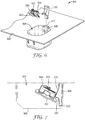
- FIGS. 6 and 7 show a packaged assembly 300 according to still another embodiment.
- the assembly 300 includes a container 302 with a chamber 304, and an appliance 350 suspended in the chamber 304 via support 320.
- the appliance 350 has a base 352, a body 354 extending outwardly from the base 352, and a partially enclosed passage 356 extending in a mesial-distal direction across the body 354. It is to be understood that other aspects of the assembly 300 not specifically discussed are similar to those previously described for assemblies 100, 200.
- support 320 includes a discrete body 322 received in the chamber 304.
- the sidewall 306 includes a channel 312 extending from the flange 310 to the bottom wall 308.
- the channel 312 may extend only partially between the flange 310 and bottom wall 308.
- the channel 312 is dimensioned to receive the body 322 and funnel towards or otherwise position the support 320 relative to the bottom wall 308.
- the body 322 includes a post 324, a canted wall portion 323 serving as a travel stop, and a recess 327 formed between the canted wall 323 and the body 322.
- the body 322 features a tapered profile to assist in insertion into the channel 312, though other profiles are possible.
- the post 324 extends outwardly from the canted wall 323, forming an angle ⁇ .
- the angle ⁇ is selected to position the appliance adjacent the container 304 opening and away from bottom wall 308. Such an orientation can make the removal of the appliance easier for practitioner or other user.
- the angle ⁇ is at least 5, at least 15, at least 20, or at least 30 degrees.
- the angle ⁇ is at most 70, at most 65, at most 60, at most 50, or at most 45 degrees.
- the support may be fixedly or releasably received in channel 312.
- supports 320 which are "fixed” to chamber are constrained such that they do not substantially move or deflect relative to the chamber 312. It is understood, however, that manufacturing tolerances may allow for one or more small gaps between the support 320 and the channel 312 and can result in a slight relative movement between these elements.
- the body 322 is press fit into the channel 312, which can have a shape that is complemental to at least a portion of the body 322 such that there is no substantial movement of the body 322 within the channel 312.
- the support 320 may be adhesively coupled to the channel 312.
- the support 320 is releasably received in the channel 312.
- Use of a releasable support 320 allows for added flexibility when inserting or extracting the appliance from the chamber 304.
- the appliance 350 may be secured to the support 320 before the support body 322 is placed into channel 312. The practitioner or other user may then remove the support 320 from the channel 312 prior to disengaging the appliance 350 from the post 324.
- Such construction may allow for a smaller chamber volume, since the chamber 304 does not necessarily need to accept gloved fingers or other hand instrument to ensure proper removal of the appliance 350.
- a portion of the base 352 is received in the recess 327 between body 322 and canted wall 323, allowing a greater portion of the post 324 to extend into the appliance passage 356.
- This configuration also allows for the canted wall 323 to abut the opening of the arch wire passage 356, offering additional security when the appliance 350 is inadvertently jostled in the chamber 304 during transit.
- the post 324 need not extend through the entire arch wire passage 356.
- FIGS. 9 and 10 depict alternative constructions for the discrete support and channel in packaged assemblies 400 and 500.
- the supports 420, 520 are constructed to position the post 424, 524, closer to the bottom wall of the chamber. Such construction may allow for larger appliances to be received in the container.
- Suitable materials for the supports 320, 420, and 520 include, for example, metallic materials (such as stainless steel), ceramic materials (such as monocrystalline or polycrystalline alumina), and plastic materials (such as fiber-reinforced polycarbonate).
- the support is integrally made as a unitary component by a metal injection molding or additive manufacturing process.
- the post may be manufactured separately and then connected directly to the canted wall by adhesive, weld, brazening, or like operation.
- Components of the support may be manufactured according to any number of methods known to the skilled artisan. These methods include, but are not limited to, milling, investment casting, metal injection molding, and additive manufacturing.
- FIGS. 11 depicts a portion of a packaged assembly 600 according to still another implementation of the present disclosure.
- the assembly 600 includes a container 602 with a chamber 604, and a discrete support 620 received the chamber 604.
- the chamber 604 includes sidewalls 606 and a generally planar bottom wall 608.
- the support 620 includes a frame 621 received adjacent the bottom wall 608 in addition to post 624 and body 622.
- the post 624 is oriented at an angle relative to the bottom wall 608 once the support 620 is placed in the package. Since the post 624 is positioned at an edge region of the support 620, material in the center 628 can be omitted to enhance removability. It is to be understood that only a partial view is shown and other aspects of the assembly 600 are similar to those previously described for the above assemblies.
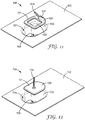
- FIGS. 12 depicts a portion of a packaged assembly 700 according to yet another implementation of the present disclosure.
- the assembly 700 includes a container 702 with a chamber 704, and a discrete support 720 received the chamber 704.
- the chamber 704 includes sidewalls 706 and a generally planar bottom wall 708.
- the support 720 includes a frame 721 received adjacent the bottom wall 708 in addition to post 724 and body 722. More similar to support 220, however, the post 724 is oriented substantially orthogonal relative to the bottom wall 708 and the frame 721. It is to be understood that only a partial view is shown and other aspects of the assembly 700 are similar to those previously described for the above assemblies.
- the base of the appliance 150 in FIGS. 1-2 is optionally coated with an orthodontic adhesive.
- the appliance 150 is then made to slide on to the post 124 until it engages the stop 122.
- the cover is then placed over both the appliance 150 and the chamber 104.
- the above methods can also apply by analogy to assemblies 200, 300, 400, 500, 600, and 700.
- the appliance may be engaged with support before or after it is placed in the chamber.
Description
- Orthodontics is a specialized area of dentistry concerned with the diagnosis and treatment of dental malocclusions to improve bite function, hygiene, and facial aesthetics. Orthodontic therapy commonly uses appliances called brackets and molar tubes which are bonded to a patient's teeth. Brackets and molar tubes contain slots and passageways, respectively, to accommodate a resilient "U"-shaped wire called an orthodontic archwire. During treatment, the archwire is secured within the slots and passageways of the brackets and molar tubes. While the archwire is initially distorted, it gradually returns to its original shape over the course of treatment, thereby applying therapeutic forces to urge the malpositioned teeth to proper locations.
- Brackets, molar tubes, and other bondable appliances are generally affixed to teeth using a suitable orthodontic adhesive. Traditionally, adhesives were painstakingly applied, one at a time, to each appliance by an orthodontic assistant at the orthodontic office. Since this can be a tedious process, manufacturers have provided appliances that are coated in advance, or "pre-coated," at the factory to save time for the orthodontist. Coated appliance configurations are described in detail in
issued U.S. Patent Nos. 4,978,007 (Jacobs, et al. ),5,015,180 (Randklev ), and5,328,363 (Chester et al. ). - Pre-coated brackets and molar tubes provide a significant advantage to the practitioner. First, these appliances provide for a high degree of precision in the amount of adhesive that is dispensed on the base of each appliance compared with hand-coating appliances. Second, these appliances are easy to use and save time, since a practitioner can conveniently remove a bracket from its respective container and place it directly on the patient's tooth without need for intervening steps. Typically, the adhesive is a light curable adhesive which allows the appliance, once placed on the tooth surface, to be carefully positioned in a proper orientation before a curing lamp is activated to cure the adhesive and securely fix the appliance in place.
- Various approaches have been taken in packaging adhesive-coated orthodontic appliances. In one approach, the appliance and adhesive are placed in a sealed "blister" or similar disposable container. The adhesive is secured against a wall of the container having a suitable release surface such that the appliance and adhesive lift off together when the appliance is plucked from the container. This approach is described in, for example,
issued U.S. Patent No. 6,183,249 (Brennan, et al. ). Another approach involves using mechanical structures to suspend the appliance in the container such that the adhesive does not contact any surfaces of the container. Examples of this approach are described inissued U.S. Patent Nos. 5,827,058 (Kelly, et al. ) and6,089,861 (Kelly, et al. ), as well as International PublicationWO/2013/162975 (Conley, etal. ). - In packaging an adhesive-coated orthodontic appliance, it can be challenging to provide ease of use in dispensing the appliance from the package while also ensuring that the appliance is properly secured during transportation and handling. Using some conventional packaging methods described in
6,183,249 (Brennan, et al. -
US 2005/241962 A1 relates to a packaged, pre-pasted orthodontic bracket comprising: a container with an open well and a top surface surrounding the well, a cover film disposed over the top opening of the well and secured to it by a layer of adhesive, and an orthodontic bracket having a base, a central portion extending from the base, at least two opposite tie wings extending from the central portion, and a layer of light-curable adhesive disposed on the base. The bracket is mounted in the hole of the cover film such that the cover film contacts the central portion of the bracket and supports the bracket with the adhesive layer and base inside the well and the tie wings outside the well. The base including a hardenable dental composition is parallel to the bottom wall. -
WO 2008/066597 A2 relates to a package for prepasted brackets. The package includes a carrier for a jigged bracket capable of supporting the jigged bracket or appliance so that uncured adhesive on a base does not contact any part of the carrier. The jigged appliance (e.g., a jigged orthodontic bracket) is mounted on a carrier and oriented parallel to a cover. -
JP H08 140994 A -
US 5 810 582 A relates to an orthodontic bracket holding and a placement apparatus for positioning of two orthodontic brackets within the apparatus. -
US 2008/044787 A1 D5 relates to a packaged orthodontic appliance with user-applied adhesive. The packaged assembly includes a container with a chamber and an orthodontic appliance received in the chamber. The assembly also includes a quantity of orthodontic adhesive material that is received on a release surface in the chamber. The appliance is detachably mounted on a support and is relatively movable when desired in order to bring a base of the appliance into contact with the adhesive material for transfer of the adhesive material to the appliance. -
US 6 834 761 B1 relates to a package for ready mountable bondable orthodontic appliances and a method of making the same. The appliances include a body and a base, the base consists of a cured layer of polymer resin and an uncured layer of polymer resin that may be lightcurable or chemically curable. The package includes a compartmented carrier with bondable appliances in the compartments and enclosed in a hermetically sealed bag. -
US 2015/021210 A1 relates to a pod for shipping prepasted orthodontic appliances. The pod includes a compartment having a cover or lid. The appliance includes uncured adhesive on its base and is removably attached to the underside of the lid and removable from the pod upon lifting of the lid. The appliance is removably mounted on the lid by a compressible clement frictionally engagable with an opening or openings of the appliance. When the lid is in closed position the appliance is suspended above the bottom of the pod so that the uncured adhesive docs not touch the interior walls of the pod. - Advantageously, the assemblies and methods of the present disclosure enable the appliance to be held securely during shipping and handling by engaging an arch wire slot or other partially enclosed passage of the appliance. This protects the appliance and also preserves the integrity of an adhesive pad on the base of the appliance. Moreover, because the support is conveniently withdrawn from the appliance as the user lifts the appliance from the package, there can be an abundance of space along the periphery of the appliance to provide easy access using tweezers or other hand instruments. Finally, by bracing the appliance within the container, these assemblies alleviate the burden on the adhesive to support the appliance during transit, leading to greater freedom in engineering the composition of the adhesive and the dimensions of the container.
- In one aspect, the present disclosure provides a packaged orthodontic assembly comprising a container with a chamber, the chamber including a sidewall and a bottom wall and the bottom wall defining a reference plane. An orthodontic appliance is received in the chamber, the appliance including a base and a passage having a lingual wall. A support extends into the chamber and is engaged with the orthodontic appliance and orients the appliance such that the lingual wall is not parallel to the reference plane.
- In another aspect, the present disclosure provides a packaged orthodontic assembly comprising a container with a chamber, the chamber including a sidewall and a bottom wall. An orthodontic appliance is received in the chamber, the appliance including a base and a partially enclosed passage. A support extends into the chamber and includes a post having a length, at least a portion of the post's length is received in the passage, securing the appliance in the container.
- In yet another aspect, the present disclosure provides a packaged orthodontic assembly comprising. A container with a chamber, the chamber including a sidewall and a bottom wall. An orthodontic appliance is received in the chamber, the appliance including a base and a partially enclosed passage, with the base including a hardenable dental composition extending across at least a portion of the base. A support is removably received in the chamber and includes a post having a length. A portion of the post's length is received in the passage, securing the appliance in the chamber.
- The words "preferred" and "preferably" refer to embodiments of the disclosure that may afford certain benefits, under certain circumstances. However, other embodiments may also be preferred, under the same or other circumstances. Furthermore, the recitation of one or more preferred embodiments does not imply that other embodiments are not useful, and is not intended to exclude other embodiments from the scope of the disclosure.
- In this application, terms such as "a", "an", and "the" are not intended to refer to only a singular entity, but include the general class of which a specific example may be used for illustration. The terms "a", "an", and "the" are used interchangeably with the term "at least one." The phrases "at least one of' and "comprises at least one of' followed by a list refers to any one of the items in the list and any combination of two or more items in the list.
- As used herein, the term "or" is generally employed in its usual sense including "and/or" unless the content clearly dictates otherwise.
- The term "and/or" means one or all of the listed elements or a combination of any two or more of the listed elements.
- Also herein, all numbers are assumed to be modified by the term "about" and preferably by the term "exactly." As used herein in connection with a measured quantity, the term "about" refers to that variation in the measured quantity as would be expected by the skilled artisan making the measurement and exercising a level of care commensurate with the objective of the measurement and the precision of the measuring equipment used.
Also herein, the recitations of numerical ranges by endpoints include all numbers subsumed within that range as well as the endpoints (e.g., 1 to 5 includes 1, 1.5, 2, 2.75, 3, 3.80, 4, 5, etc.). - As used herein as a modifier to a property or attribute, the term "generally", unless otherwise specifically defined, means that the property or attribute would be readily recognizable by a person of ordinary skill but without requiring absolute precision or a perfect match (e.g., within +/- 20 % for quantifiable properties). The term "substantially", unless otherwise specifically defined, means to a high degree of approximation (e.g., within +/- 10% for quantifiable properties) but again without requiring absolute precision or a perfect match. Terms such as same, equal, uniform, constant, strictly, and the like, are understood to be within the usual tolerances or measuring error applicable to the particular circumstance rather than requiring absolute precision or a perfect match.
- The above summary of the present disclosure is not intended to describe each disclosed embodiment or every implementation of the present disclosure. The description that follows more particularly exemplifies illustrative embodiments. In several places throughout the application, guidance is provided through lists of examples, which examples can be used in various combinations. In each instance, the recited list serves only as a representative group and should not be interpreted as an exclusive list.
-
-
FIG. 1 is a cut-away, isometric view of a packaged orthodontic assembly according to one embodiment of the present disclosure; -
FIG. 2 is an exploded view of the assembly ofFIG. 1 ; -
FIG. 3 is a side cross-sectional view of the packaged orthodontic assembly ofFIG. 1 ; -
FIG. 4 is an isometric view of a container for receiving an orthodontic appliance according to another embodiment of the present disclosure; -
FIG. 5 is a fragmentary, cross-sectional plan view of the container ofFIG. 4 , including an appliance received in a chamber. -
FIG. 6 is an exploded, isometric view of a packaged orthodontic assembly according to another embodiment of the present disclosure; -
FIG. 7 is a side cross-sectional view of the packaged orthodontic assembly ofFIG. 6 ; -
FIG. 8 is an isometric view of the appliance support structure depicted inFIGS. 6 and 7 ; -
FIG. 9 is an exploded, isometric view of a package including a removable support structure according to another embodiment of the present disclosure; -
FIG. 10 is an exploded, isometric view of a package including a removable support structure according to yet another embodiment of the present disclosure; -
FIG. 11 is an exploded, isometric view of a package including a removable support structure according to yet another embodiment of the present disclosure; and -
FIG. 12 is an exploded, isometric view of a package including a removable support structure according to still yet another embodiment of the present disclosure - While the above-identified figures set forth several embodiments of the disclosure other embodiments are also contemplated, as noted in the description. In all cases, this disclosure presents the invention by way of representation and not limitation. It should be understood that numerous other modifications and embodiments can be devised by those skilled in the art, which fall within the scope and spirit of the principles of the invention.
- As used herein:
- "Mesial" means in a direction toward the center of the patient's curved dental arch.
- "Distal" means in a direction away from the center of the patient's curved dental arch.
- "Occlusal" means in a direction toward the outer tips of the patient's teeth.
- "Gingival" means in a direction toward the patient's gums or gingiva.
- "Facial" means in a direction toward the patient's lips or cheeks.
- "Lingual" means in a direction toward the patient's tongue.
- According to one exemplary embodiment,
FIG. 1 shows a packaged orthodontic assembly designated by the numeral 100. Theorthodontic assembly 100 includes acontainer 102 having achamber 104, and anappliance 150 received in thechamber 104. Theappliance 150 is secured in thechamber 104 viasupport structure 120, which engages an arch wire passage in the appliance body. - The
chamber 104 is partially defined byvertical sidewall 106 and ahorizontal bottom wall 108. Thebottom wall 108 is generally planar and defines areference plane 109. In the depicted embodiment, thebottom wall 108 andreference plane 109 are oval-shaped, thought other shapes (e.g., circular, quadrilateral, etc.) may be suitable in other implementations. Theside wall 106 is integrally connected to thebottom wall 108 and is slightly angled relative to thereference plane 109. Alternatively, theside wall 106 may be substantially orthogonal to thereference plane 109. Thesidewall 106 in the depicted embodiment defines an oval in plan view, but likebottom wall 108 may define other shapes as desired. Anupper edge 107 of thesidewall 106 is connected to aflange 110 that surrounds thechamber 104. Theflange 110 is typically, substantially parallel with thereference plane 109. - An
orthodontic appliance 150 is suspended in thechamber 104. As shown, theappliance 150 is a buccal tube: a molar appliance having a base 152 and abody 154 extending outwardly from thebase 150. Thebody 154 includes wall sections defining apassage 156 that extends in a mesial-distal direction across the body for receipt of an archwire. Thepassage 156 is partially enclosed, in that it is only accessible via its opposing ends. In other embodiments, a partially enclosed passage in the appliance body may include a wall section that does not extend across the length of body or other corresponding wall sections, resulting in openings or access points in addition to the opposing ends. Thebase 152 has abonding surface 159 adapted for attachment to a tooth surface and optionally an adhesive (not shown) extending across at least a portion of thebonding surface 159. It is to be understood that thecontainer 104 could be adapted for use with other orthodontic appliances, including, for example, brackets, buttons, cleats, and sheaths. Moreover, theappliance 150 may be suitable for attachment either to the labial or lingual surface of the patient's teeth. - As best illustrated in
FIGS. 2 and3 , theappliance support structure 120 includes asupport body 121 and apost 124 extending into thechamber 104 in the general direction of theupper edge 107 andflange 110. Thesupport body 121 extends between a portion of thepost 124 and thebottom wall 108 and orients thepost 124 at an angle θ relative to thesidewall 106. In certain circumstances, the angle θ is selected to position the appliance adjacent the container opening. Such an orientation can render the removal of the appliance easier for a practitioner or other user. In some embodiments, the angle θ is at least 5, at least 15, at least 20, or at least 30 degrees. In some embodiments, the angle θ is at most 90, at most 75, at most 60, at most 50, or at most 45 degrees. - As can be seen in
Fig, 3 , thesupport structure 120 includes anenlarged stop 122 where thebody 121 transitions to thepost 124. Thestop 122 can provide a limit of travel for an engagedappliance 150, preventing theappliance 150 or the adhesive (if present) from contacting thebottom wall 108,side wall 106, orsupport body 121. In certain implementations, thestop 122 includes a portion ofbody 121 having cross-sectional dimensions greater than the cross-sectional dimensions of thearch wire passage 156 on theappliance 150. Thestop 122 may further include anangled fin 123 designed to assist in fixing the location ofpost 124 within the chamber. Thefin 123 may also, in certain embodiments, contact a portion of thebase 152 of theappliance 150 when theappliance 150 is received on thepost 124. In other implementations, thefin 123 serves as a tactile indicator that theappliance 150 has been placed on thepost 124 in the desired orientation. - The
post 124 extends from thebody 122 to afree end 126 positioned at acertain height 127 relative to thebottom wall 108. Theheight 127 is typically selected to be less than the height "h" ofside wall 106, so that substantial portion of theappliance 150 remains below theflange 110. In one exemplary construction, theheight 127 of the post is 0.655 cm (0.258 inches) and the height of thesidewall 106 is 0.699 cm (0.275 inches). - The length 125 of the
post 124 can, as depicted inFIG. 3 , be sufficient to extend through thepassage 156 of the appliance, such that theend 126 is disposed outside thepassage 156. In alternative implementations, thepost 124 extends through a lesser portion of thepassage 156. - The
post 124 includes a rectangular-shaped cross-section. The cross-sectional dimensions of thepost 124 can, in certain advantageous circumstances, correspond to dimensions of thearch wire passage 156. Thepost 124 may further include a taper along its length 125, such that at least one cross-sectional dimension at the base of thepost 124 nearstop 122 is greater than the corresponding dimension at theend 126. In other implementations, the cross-sectional dimensions of thepost 124 are substantially constant along its length 125. Thepost 124 can feature other configurations, including for example, polyhedral, conical, frusto-conical, pyramidal, frusto-pyramidal, cylindrical, and combinations thereof. - As a result of the mechanical engagement between the
arch wire passage 156 and thepost 124, theappliance 150 is suspended in a relatively fixed position above thebottom wall 108. In this position, theappliance 150 and its associated adhesive (if present) are vertically spaced apart from thebottom wall 108 and horizontally spaced apart fromside wall 106, thus avoiding substantial contact between the adhesive and thecontainer 104. Moreover, no wall section of thepassage 156 is parallel or substantially parallel to thereference plane 109, particularlywall section 157 nearest to thebottom wall 108, In the depicted embodiment,wall section 157 is a lingual wall. - In certain implementations, the post can be sufficiently soft that a portion compressively deforms upon the urging of the
appliance 150 toward thesupport body 121. This deformation, which may be elastic, plastic, or a combination of both, can result in the post closely conforming with the interior ofpassage 156, resulting in a more secure engagement betweenappliance 150 andsupport 120. This can be especially useful where there is significant variation amongst the geometries of different appliances. Such variation may be due to differences in prescription (e.g., torque and angulation) base sizes, minor defects, or even manufacturing tolerances. The dimensions of the arch wire receiving passage, by contrast, are less varied and more predictable. For example, some appliance types are often offered having one of two prescribed slot dimensions: 0.4572 cm (0.18 inches) and 0.5588 cm (0.22 inches). Constructing a post to generally correspond to these dimensions significantly reduces the number of different containers that must be manufactured, and reduces the impact of manufacturing tolerances elsewhere in the bracket or container. Furthermore, since the dimensions of the arch wire slot are part of the appliance prescription, close adherence to these dimensions by appliance manufacturers is paramount. By usingposts 124, deformable or otherwise, designed to engage an arch wire passage instead of other appliance undercuts it is possible to afford a configuration for thecontainer 102 that can accommodate a wide variety ofappliances 150 in thechamber 104. - In other embodiments, the support has one or more features that mechanically register with slots, grooves or other recesses located on the
orthodontic appliance 150. In one such example, the support includes an arm extending outward from the sidewall at an angle θ (relative to the side wall) to an outer end. The outer end includes two sections spaced from each other to present a receptacle therebetween. Theappliance 150 may be received in the receptacle, such that the wall sections of the passage are non-parallel to thereference plane 109. Other aspects of such receptacle containing supports are described inUS Patent No. 7,841,464 (Cinader et al. ). - The
container 102 can be made from any of a number of suitable materials known in the art. If an adhesive is present and is light-sensitive, the walls of thechamber 104 can be made from a suitable light-blocking material, such as a polymeric-metal laminate or metal-filled polymer composite described inU.S. Patent Publication No. 2003/0196914 (Tzou et al. ). Thecontainer 102 can also be formed using any of a number of known polymer processing methods, such as extrusion, injection molding, or thermoforming. In some embodiments, the polymer composite is based on a resilient thermoplastic such as polypropylene. In presently preferred implementations of the embodiment ofFIGS. 1-3 , thesidewall 106, thebottom wall 108, thesupport 120, and theflange 110 are integrally molded or otherwise formed as a unitary component. - If present on the
bonding surface 159 of theappliance 150, an orthodontic adhesive may include any of a variety of bonding compositions known in the art. In presently preferred implementations, the orthodontic adhesive is a light curable adhesive that is hardenable by exposure to actinic radiation. Suitable adhesives include, for example, TRANSBOND XT brand Light Cure Adhesive and TRANSBOND PLUS brand Color Change Adhesive, both available from 3M Unitek. As another option, the adhesive can include compressible material, as described inU.S. Patent Publication Nos. 2008/0096150 (Cinader ) and2009/0233252 (Cinader ). Further aspects of adhesive pre-coated appliances are described inU.S. Patent Nos. 5,575,645 (Jacobs, et al. ),6,960,079 (Brennan et al. ), and7,910,632 (Cinader et al. ). - The
container 102 can also include a cover (not shown) that is releasably connected to theflange 110 by a section of adhesive. Suitable constructions and materials for the cover and adhesive are described in the aforementionedU.S. Pat. Nos. 5,328,363 (Chester, et al. ) and5,575,645 (Jacobs, et al. ), as well asU.S. Publication No. 2003/0196914 (Tzou, et al. ). Alternatively, the cover may be connected to theflange 110 by a heat seal. In its closed position, the cover extends over the opening of thechamber 104 and helps protect theappliance 150 and the adhesive material (if used) from exposure to light, moisture and contaminants. The cover can include a tab that extends past theflange 110 for gripping by the practitioner when it is desired to move the cover from a closed position to an open position. -
FIGS. 4 and5 show a packagedassembly 200 according to another embodiment. Theassembly 200 includes acontainer 202 with achamber 204, and anappliance 250 received on asupport 220. As before, theappliance 250 has abase 252, abody 254 extending outwardly from thebase 252 and a partially enclosedarch wire passage 256. It is to be understood that other aspects of theassembly 200 not specifically discussed are similar to those previously described forassembly 100. Theassembly 200 differs from previous embodiments in that thesupport 220 includes apost 224 extending into thechamber 204 from abottom wall 208. Thepost 224 is oriented substantially orthogonal to thebottom wall 208 and reference plane 209. Thepost 254 also orients at least two wall sections of thepassage 256 substantially orthogonal to thebottom wall 208. - The
post 224 includes a taper along itslength 225, such that at least one cross-sectional dimension at the base of thepost 224 adjacent thebottom wall 208 is greater than the corresponding dimension at theend 226. The tapered profile prevents thebase 252 of the appliance 205 and adhesive, if used, from contacting thebottom wall 208. Suitable post shapes in this embodiment also include without limitation frusto-conical, pyramidal and frusto-pyramidal. -
FIGS. 6 and 7 show a packagedassembly 300 according to still another embodiment. Theassembly 300 includes acontainer 302 with achamber 304, and anappliance 350 suspended in thechamber 304 viasupport 320. As before, theappliance 350 has abase 352, abody 354 extending outwardly from thebase 352, and a partiallyenclosed passage 356 extending in a mesial-distal direction across thebody 354. It is to be understood that other aspects of theassembly 300 not specifically discussed are similar to those previously described forassemblies - In contrast to the integral support structures of the prior embodiments,
support 320 includes adiscrete body 322 received in thechamber 304. Thesidewall 306 includes achannel 312 extending from the flange 310 to thebottom wall 308. In other embodiments, thechannel 312 may extend only partially between the flange 310 andbottom wall 308. Thechannel 312 is dimensioned to receive thebody 322 and funnel towards or otherwise position thesupport 320 relative to thebottom wall 308. - Turning briefly to
FIG. 8 , thebody 322 includes apost 324, acanted wall portion 323 serving as a travel stop, and arecess 327 formed between thecanted wall 323 and thebody 322. Thebody 322 features a tapered profile to assist in insertion into thechannel 312, though other profiles are possible. Thepost 324 extends outwardly from the cantedwall 323, forming an angle α. In certain circumstances, the angle α is selected to position the appliance adjacent thecontainer 304 opening and away frombottom wall 308. Such an orientation can make the removal of the appliance easier for practitioner or other user. In some embodiments, the angle α is at least 5, at least 15, at least 20, or at least 30 degrees. In some embodiments, the angle α is at most 70, at most 65, at most 60, at most 50, or at most 45 degrees. - The support may be fixedly or releasably received in
channel 312. As defined herein, supports 320 which are "fixed" to chamber are constrained such that they do not substantially move or deflect relative to thechamber 312. It is understood, however, that manufacturing tolerances may allow for one or more small gaps between thesupport 320 and thechannel 312 and can result in a slight relative movement between these elements. In one example, thebody 322 is press fit into thechannel 312, which can have a shape that is complemental to at least a portion of thebody 322 such that there is no substantial movement of thebody 322 within thechannel 312. Alternatively, thesupport 320 may be adhesively coupled to thechannel 312. - In the embodiment depicted in
FIGS. 6-7 , thesupport 320 is releasably received in thechannel 312. Use of areleasable support 320 allows for added flexibility when inserting or extracting the appliance from thechamber 304. In one alternative, theappliance 350 may be secured to thesupport 320 before thesupport body 322 is placed intochannel 312. The practitioner or other user may then remove thesupport 320 from thechannel 312 prior to disengaging theappliance 350 from thepost 324. Such construction may allow for a smaller chamber volume, since thechamber 304 does not necessarily need to accept gloved fingers or other hand instrument to ensure proper removal of theappliance 350. - As can be appreciated by reference to
FIG. 7 , a portion of thebase 352 is received in therecess 327 betweenbody 322 and cantedwall 323, allowing a greater portion of thepost 324 to extend into theappliance passage 356. This configuration also allows for thecanted wall 323 to abut the opening of thearch wire passage 356, offering additional security when theappliance 350 is inadvertently jostled in thechamber 304 during transit. As a partial consequence, thepost 324 need not extend through the entirearch wire passage 356. -
FIGS. 9 and 10 depict alternative constructions for the discrete support and channel in packaged assemblies 400 and 500. Notably, thesupports 420, 520 are constructed to position thepost - Suitable materials for the
supports -
FIGS. 11 depicts a portion of a packagedassembly 600 according to still another implementation of the present disclosure. Theassembly 600 includes acontainer 602 with achamber 604, and adiscrete support 620 received thechamber 604. Thechamber 604 includessidewalls 606 and a generally planarbottom wall 608. Instead of a channel, however, thesupport 620 includes aframe 621 received adjacent thebottom wall 608 in addition to post 624 andbody 622. Similar to support 120, however, thepost 624 is oriented at an angle relative to thebottom wall 608 once thesupport 620 is placed in the package. Since thepost 624 is positioned at an edge region of thesupport 620, material in thecenter 628 can be omitted to enhance removability. It is to be understood that only a partial view is shown and other aspects of theassembly 600 are similar to those previously described for the above assemblies. -
FIGS. 12 depicts a portion of a packagedassembly 700 according to yet another implementation of the present disclosure. Theassembly 700 includes acontainer 702 with achamber 704, and adiscrete support 720 received thechamber 704. Thechamber 704 includessidewalls 706 and a generally planarbottom wall 708. Likeassembly 600, thesupport 720 includes aframe 721 received adjacent thebottom wall 708 in addition to post 724 and body 722. More similar to support 220, however, thepost 724 is oriented substantially orthogonal relative to thebottom wall 708 and theframe 721. It is to be understood that only a partial view is shown and other aspects of theassembly 700 are similar to those previously described for the above assemblies. - In an exemplary method of packaging an
orthodontic assembly 100, the base of theappliance 150 inFIGS. 1-2 is optionally coated with an orthodontic adhesive. Theappliance 150 is then made to slide on to thepost 124 until it engages thestop 122. To seal theappliance 150 from light, moisture, and/or contaminants, the cover is then placed over both theappliance 150 and thechamber 104. - It is understood that the above methods can also apply by analogy to
assemblies
Claims (13)
- A packaged orthodontic assembly (100) comprising:a container (102) with a chamber (104), the chamber including a sidewall (106) and a bottom wall (108), the bottom wall defining a reference plane (109), wherein the sidewall comprises an upper edge (107) connected to a flange (110) that surrounds the chamber, and wherein the flange is substantially parallel to the reference plane;an orthodontic appliance (150) received in the chamber, the appliance including a base (152) comprising a bonding surface (159) and a body (154) extending outward from the base and comprising an arch wire passage (156); anda support (120) extending into the chamber, wherein the support comprises a support body (121) that tapers into an elongate linear post (124) extending along a direction from the bottom wall of the chamber toward the upper edge of the sidewall and forming an oblique angle relative to the sidewall adjacent to the support body,wherein at least a portion of the linear post is engaged with the arch wire passage (156) in the orthodontic appliance and orients the appliance such that the base is not parallel to the reference plane.
- The assembly of claim 1, wherein a cross-sectional dimension varies along the length of the post.
- The assembly of claim 1, wherein the post comprises a free end (126) positioned at a height below the flange that surrounds the chamber.
- The assembly of claim 1, wherein the support extends from a frame (621, 721) removably receivable in the chamber, wherein the support body extends from an upper side of the frame, and wherein an underside of the frame opposite the upper side thereof is received adjacent to the bottom wall of the chamber.
- The assembly of claim 4, wherein the frame comprises an aperture.
- The assembly of claim 1, wherein the support comprises an enlarged stop (122) wherein the support body transitions to the linear post, and wherein the enlarged stop has a cross-sectional dimension greater than the cross-sectional dimension of the arch wire passage (156) in the orthodontic appliance.
- The assembly of claim 6, wherein the support body comprises an angled fin (123) that contacts the base of the orthodontic appliance when the arch wire passage (156) of the orthodontic appliance is received on the linear post.
- The assembly of claim 1, wherein the linear post tapers along the length thereof.
- The assembly of claim 1, wherein the linear post is elastically deformable, plastically deformable, or a combination thereof.
- The assembly of claim 1, wherein the base of the orthodontic appliance includes a hardenable dental composition extending across at least a portion of the base.
- A method for packaging an orthodontic appliance (150), the orthodontic appliance comprising a base (152) with an adhesive layer and a body (154) extending outward from the base, the body comprising an arch wire passage (156), the method comprising:providing a container (102) with a chamber (104) including a sidewall (106) and a bottom wall (108), wherein the sidewall comprises an upper edge (107) connected to a flange (110) that surrounds the chamber, and wherein the flange is substantially parallel to the bottom wall of the chamber;providing a frame (621) configured to removably mount in the chamber, wherein the frame comprises an upper side comprising a support for the orthodontic appliance, the support comprising a support body that tapers into an elongate deformable linear post (124);mounting the orthodontic appliance on the elongate deformable linear post such that at least a portion of the elongate deformable linear post conforms with an interior of the arch wire passage (156) in the orthodontic appliance to removably secure the orthodontic appliance on the post; andinserting the frame in the chamber such that a lower side thereof is received on the bottom wall of the chamber and the elongate deformable linear post extends along a direction from the bottom wall of the chamber toward the upper edge of the sidewall and forms an oblique angle relative to the sidewall adjacent to the support body such that the base of the orthodontic appliance removably secured on the post is spaced apart from the bottom wall and is not parallel to the reference plane.
- The method of claim 11, further comprising applying a cover over the chamber, wherein the cover is releasably connected to the flange on the container with an adhesive.
- The method of claim 12, wherein the cover comprises a tab that extends past the flange of the container.
Applications Claiming Priority (2)
| Application Number | Priority Date | Filing Date | Title |
|---|---|---|---|
| US201562131003P | 2015-03-10 | 2015-03-10 | |
| PCT/US2016/021231 WO2016144896A1 (en) | 2015-03-10 | 2016-03-07 | Packaged orthodontic assembly with angled support structure |
Publications (3)
| Publication Number | Publication Date |
|---|---|
| EP3267937A1 EP3267937A1 (en) | 2018-01-17 |
| EP3267937A4 EP3267937A4 (en) | 2018-10-31 |
| EP3267937B1 true EP3267937B1 (en) | 2020-07-01 |
Family
ID=56879577
Family Applications (1)
| Application Number | Title | Priority Date | Filing Date |
|---|---|---|---|
| EP16762310.7A Active EP3267937B1 (en) | 2015-03-10 | 2016-03-07 | Packaged orthodontic assembly with angled support structure |
Country Status (5)
| Country | Link |
|---|---|
| US (1) | US10307232B2 (en) |
| EP (1) | EP3267937B1 (en) |
| JP (1) | JP6796590B2 (en) |
| CN (1) | CN107427351B (en) |
| WO (1) | WO2016144896A1 (en) |
Families Citing this family (3)
| Publication number | Priority date | Publication date | Assignee | Title |
|---|---|---|---|---|
| CN111114967A (en) * | 2017-05-23 | 2020-05-08 | 吉利 | Bracket placing groove of bracket packaging box |
| WO2019051188A1 (en) * | 2017-09-07 | 2019-03-14 | Ormco Corporation | Orthodontic storage and dispensing systems, packages, and methods of making and using same |
| US20210386523A1 (en) * | 2018-12-31 | 2021-12-16 | 3M Innovative Properties Company | Orthodontic indirect bonding apparatus |
Family Cites Families (33)
| Publication number | Priority date | Publication date | Assignee | Title |
|---|---|---|---|---|
| US1992950A (en) | 1932-10-14 | 1935-03-05 | Barber Colman Co | Packing of rotary cutters |
| US3529716A (en) * | 1967-10-12 | 1970-09-22 | Oconnell Paula A | Clip for packaging of,for example,hair curlers |
| US5015180A (en) | 1989-03-01 | 1991-05-14 | Minnesota Mining And Manufacturing Company | Dental article containing light-curable paste |
| US4978007A (en) | 1989-05-10 | 1990-12-18 | Minnesota Mining And Manufacturing Company | Packaging curable materials |
| EP0689803B1 (en) * | 1991-08-02 | 2000-04-05 | Minnesota Mining And Manufacturing Company | Dental packaging assembly |
| US5354199A (en) | 1991-08-02 | 1994-10-11 | Minnesota Mining And Manufacturing Company | Adhesive for packaged orthodontic appliance |
| US5256062A (en) * | 1992-06-30 | 1993-10-26 | Johnson & Johnson Consumer Products, Inc. | Combination metallic ceramic orthodontic bracker |
| JPH08140994A (en) | 1994-11-16 | 1996-06-04 | Chikami Mirutetsuku Kk | Container for storing orthodontic appliance |
| US5538129A (en) * | 1995-03-21 | 1996-07-23 | Minnesota Mining And Manufacturing Company | Package for adhesive precoated dental appliance |
| US5810582A (en) | 1996-07-02 | 1998-09-22 | Doyle; Walter A. | Orthodontic bracket holding and placement apparatus |
| US5827058A (en) | 1997-10-08 | 1998-10-27 | Minnesota Mining & Manufacturing Co. | Carrier for supporting orthodontic brackets |
| US6183249B1 (en) | 1999-07-29 | 2001-02-06 | 3M Innovative Properties Company | Release substrate for adhesive precoated orthodontic appliances |
| US20030196914A1 (en) | 2002-04-18 | 2003-10-23 | 3M Innovative Properties Company | Containers for photocurable materials |
| US6960079B2 (en) | 2002-04-18 | 2005-11-01 | 3M Innovative Properties Company | Orthodontic adhesives and appliances including an adhesive on the base of the appliance |
| US6834761B1 (en) * | 2002-12-17 | 2004-12-28 | Tp Orthodontics, Inc. | Package for ready mountable bondable orthodontic appliances and method of making same |
| US20050133384A1 (en) | 2003-12-19 | 2005-06-23 | 3M Innovative Properties Company | Packaged orthodontic assembly with adhesive precoated appliances |
| US7381053B2 (en) * | 2004-04-10 | 2008-06-03 | American Orthodontics Corporation | Packaging system for pre-pasted orthodontic bracket |
| US20070142498A1 (en) * | 2005-12-20 | 2007-06-21 | Brennan Joan V | Dental compositions including thermally responsive additives, and the use thereof |
| US7841464B2 (en) | 2006-06-21 | 2010-11-30 | 3M Innovative Properties Company | Packaged orthodontic appliance with user-applied adhesive |
| US20080096150A1 (en) | 2006-10-23 | 2008-04-24 | 3M Innovative Properties Company | Dental articles, methods, and kits including a compressible material |
| US9539065B2 (en) | 2006-10-23 | 2017-01-10 | 3M Innovative Properties Company | Assemblies, methods, and kits including a compressible material |
| US7469783B2 (en) | 2006-11-30 | 2008-12-30 | Tp Orthodontics, Inc. | Package for prepasted brackets |
| US7726470B2 (en) | 2007-05-18 | 2010-06-01 | 3M Innovative Properties Company | Packaged orthodontic appliance and adhesive material |
| CN201101593Y (en) * | 2007-09-29 | 2008-08-20 | 邢树林 | Oral cavity needle set case |
| WO2010039395A2 (en) | 2008-09-30 | 2010-04-08 | 3M Innovative Properties Company | Orthodontic composition with heat modified minerals |
| JP5518551B2 (en) * | 2010-04-13 | 2014-06-11 | 株式会社ジーシー | Storage container for implant fixture |
| JP5422081B2 (en) * | 2010-06-02 | 2014-02-19 | スリーエム イノベイティブ プロパティズ カンパニー | Packaged orthodontic assembly with retaining member |
| CN202060902U (en) * | 2011-04-26 | 2011-12-07 | 潘兴哲 | Self-locking bracket for dental orthodontics |
| JP6305393B2 (en) | 2012-04-27 | 2018-04-04 | スリーエム イノベイティブ プロパティズ カンパニー | Container for orthodontic appliance |
| US20140374282A1 (en) * | 2012-11-26 | 2014-12-25 | 3M Innovative Properties Company | Packaged orthodontic assembly with retaining member |
| US8925719B2 (en) * | 2013-03-14 | 2015-01-06 | Tp Orthodontics, Inc. | Package for prepasted brackets |
| CN103263302B (en) * | 2013-05-09 | 2015-10-28 | 四川大学 | The high transparency ceramic bracket preparation method of mouth cavity orthodontic |
| US9113984B2 (en) * | 2013-07-18 | 2015-08-25 | Tp Orthodontics, Inc. | Pod for shipping prepasted orthodontic appliances |
-
2016
- 2016-03-07 WO PCT/US2016/021231 patent/WO2016144896A1/en active Application Filing
- 2016-03-07 JP JP2017546956A patent/JP6796590B2/en active Active
- 2016-03-07 CN CN201680013447.XA patent/CN107427351B/en not_active Expired - Fee Related
- 2016-03-07 EP EP16762310.7A patent/EP3267937B1/en active Active
- 2016-03-07 US US15/554,359 patent/US10307232B2/en active Active
Non-Patent Citations (1)
| Title |
|---|
| None * |
Also Published As
| Publication number | Publication date |
|---|---|
| US20180177577A1 (en) | 2018-06-28 |
| JP6796590B2 (en) | 2020-12-09 |
| US10307232B2 (en) | 2019-06-04 |
| CN107427351B (en) | 2020-08-18 |
| EP3267937A4 (en) | 2018-10-31 |
| CN107427351A (en) | 2017-12-01 |
| EP3267937A1 (en) | 2018-01-17 |
| JP2018509214A (en) | 2018-04-05 |
| WO2016144896A1 (en) | 2016-09-15 |
Similar Documents
| Publication | Publication Date | Title |
|---|---|---|
| US9925025B2 (en) | Container for orthodontic appliances | |
| JP5422081B2 (en) | Packaged orthodontic assembly with retaining member | |
| US8550814B1 (en) | Multi-component orthodontic bracket assembly | |
| US7841464B2 (en) | Packaged orthodontic appliance with user-applied adhesive | |
| US7762815B2 (en) | Method of making an indirect bonding tray for orthodontic treatment | |
| US9439737B2 (en) | Orthodontic indirect bonding tray including stabilization features | |
| JP5051561B1 (en) | Orthodontic appliance installation tool | |
| US20160074139A1 (en) | Indirect Bonding Tray and Method of Manufacture Thereof | |
| KR101565802B1 (en) | Tooth correction device and tooth correction method using tooth correction device | |
| EP3267937B1 (en) | Packaged orthodontic assembly with angled support structure | |
| KR20140138937A (en) | Tube for orthodontics | |
| US10675128B2 (en) | Orthodontic system and method of use | |
| US20210068929A1 (en) | Orthodontic Appliance with Increased Torsional Control | |
| US20210386523A1 (en) | Orthodontic indirect bonding apparatus | |
| US11759293B2 (en) | Orthodontic system and method of use | |
| US20140374282A1 (en) | Packaged orthodontic assembly with retaining member | |
| JP2022551353A (en) | Custom appliances for bonding orthodontic appliances and methods of designing and using custom appliances | |
| JP7373665B2 (en) | Custom appliance for bonding orthodontic appliances and method for bonding orthodontic appliances |
Legal Events
| Date | Code | Title | Description |
|---|---|---|---|
| STAA | Information on the status of an ep patent application or granted ep patent |
Free format text: STATUS: THE INTERNATIONAL PUBLICATION HAS BEEN MADE |
|
| PUAI | Public reference made under article 153(3) epc to a published international application that has entered the european phase |
Free format text: ORIGINAL CODE: 0009012 |
|
| STAA | Information on the status of an ep patent application or granted ep patent |
Free format text: STATUS: REQUEST FOR EXAMINATION WAS MADE |
|
| 17P | Request for examination filed |
Effective date: 20170828 |
|
| AK | Designated contracting states |
Kind code of ref document: A1 Designated state(s): AL AT BE BG CH CY CZ DE DK EE ES FI FR GB GR HR HU IE IS IT LI LT LU LV MC MK MT NL NO PL PT RO RS SE SI SK SM TR |
|
| AX | Request for extension of the european patent |
Extension state: BA ME |
|
| DAV | Request for validation of the european patent (deleted) | ||
| DAX | Request for extension of the european patent (deleted) | ||
| A4 | Supplementary search report drawn up and despatched |
Effective date: 20181001 |
|
| RIC1 | Information provided on ipc code assigned before grant |
Ipc: B65D 25/10 20060101ALI20180925BHEP Ipc: A61C 19/02 20060101AFI20180925BHEP Ipc: A61C 7/12 20060101ALI20180925BHEP |
|
| GRAP | Despatch of communication of intention to grant a patent |
Free format text: ORIGINAL CODE: EPIDOSNIGR1 |
|
| STAA | Information on the status of an ep patent application or granted ep patent |
Free format text: STATUS: GRANT OF PATENT IS INTENDED |
|
| INTG | Intention to grant announced |
Effective date: 20200117 |
|
| GRAS | Grant fee paid |
Free format text: ORIGINAL CODE: EPIDOSNIGR3 |
|
| GRAA | (expected) grant |
Free format text: ORIGINAL CODE: 0009210 |
|
| STAA | Information on the status of an ep patent application or granted ep patent |
Free format text: STATUS: THE PATENT HAS BEEN GRANTED |
|
| AK | Designated contracting states |
Kind code of ref document: B1 Designated state(s): AL AT BE BG CH CY CZ DE DK EE ES FI FR GB GR HR HU IE IS IT LI LT LU LV MC MK MT NL NO PL PT RO RS SE SI SK SM TR |
|
| REG | Reference to a national code |
Ref country code: CH Ref legal event code: EP Ref country code: AT Ref legal event code: REF Ref document number: 1285425 Country of ref document: AT Kind code of ref document: T Effective date: 20200715 |
|
| REG | Reference to a national code |
Ref country code: IE Ref legal event code: FG4D |
|
| REG | Reference to a national code |
Ref country code: DE Ref legal event code: R096 Ref document number: 602016039155 Country of ref document: DE |
|
| REG | Reference to a national code |
Ref country code: LT Ref legal event code: MG4D |
|
| PG25 | Lapsed in a contracting state [announced via postgrant information from national office to epo] |
Ref country code: BG Free format text: LAPSE BECAUSE OF FAILURE TO SUBMIT A TRANSLATION OF THE DESCRIPTION OR TO PAY THE FEE WITHIN THE PRESCRIBED TIME-LIMIT Effective date: 20201001 |
|
| REG | Reference to a national code |
Ref country code: NL Ref legal event code: MP Effective date: 20200701 |
|
| REG | Reference to a national code |
Ref country code: AT Ref legal event code: MK05 Ref document number: 1285425 Country of ref document: AT Kind code of ref document: T Effective date: 20200701 |
|
| PG25 | Lapsed in a contracting state [announced via postgrant information from national office to epo] |
Ref country code: CZ Free format text: LAPSE BECAUSE OF FAILURE TO SUBMIT A TRANSLATION OF THE DESCRIPTION OR TO PAY THE FEE WITHIN THE PRESCRIBED TIME-LIMIT Effective date: 20200701 Ref country code: FI Free format text: LAPSE BECAUSE OF FAILURE TO SUBMIT A TRANSLATION OF THE DESCRIPTION OR TO PAY THE FEE WITHIN THE PRESCRIBED TIME-LIMIT Effective date: 20200701 Ref country code: SE Free format text: LAPSE BECAUSE OF FAILURE TO SUBMIT A TRANSLATION OF THE DESCRIPTION OR TO PAY THE FEE WITHIN THE PRESCRIBED TIME-LIMIT Effective date: 20200701 Ref country code: PT Free format text: LAPSE BECAUSE OF FAILURE TO SUBMIT A TRANSLATION OF THE DESCRIPTION OR TO PAY THE FEE WITHIN THE PRESCRIBED TIME-LIMIT Effective date: 20201102 Ref country code: AT Free format text: LAPSE BECAUSE OF FAILURE TO SUBMIT A TRANSLATION OF THE DESCRIPTION OR TO PAY THE FEE WITHIN THE PRESCRIBED TIME-LIMIT Effective date: 20200701 Ref country code: HR Free format text: LAPSE BECAUSE OF FAILURE TO SUBMIT A TRANSLATION OF THE DESCRIPTION OR TO PAY THE FEE WITHIN THE PRESCRIBED TIME-LIMIT Effective date: 20200701 Ref country code: LT Free format text: LAPSE BECAUSE OF FAILURE TO SUBMIT A TRANSLATION OF THE DESCRIPTION OR TO PAY THE FEE WITHIN THE PRESCRIBED TIME-LIMIT Effective date: 20200701 Ref country code: GR Free format text: LAPSE BECAUSE OF FAILURE TO SUBMIT A TRANSLATION OF THE DESCRIPTION OR TO PAY THE FEE WITHIN THE PRESCRIBED TIME-LIMIT Effective date: 20201002 Ref country code: NO Free format text: LAPSE BECAUSE OF FAILURE TO SUBMIT A TRANSLATION OF THE DESCRIPTION OR TO PAY THE FEE WITHIN THE PRESCRIBED TIME-LIMIT Effective date: 20201001 Ref country code: ES Free format text: LAPSE BECAUSE OF FAILURE TO SUBMIT A TRANSLATION OF THE DESCRIPTION OR TO PAY THE FEE WITHIN THE PRESCRIBED TIME-LIMIT Effective date: 20200701 |
|
| PG25 | Lapsed in a contracting state [announced via postgrant information from national office to epo] |
Ref country code: LV Free format text: LAPSE BECAUSE OF FAILURE TO SUBMIT A TRANSLATION OF THE DESCRIPTION OR TO PAY THE FEE WITHIN THE PRESCRIBED TIME-LIMIT Effective date: 20200701 Ref country code: PL Free format text: LAPSE BECAUSE OF FAILURE TO SUBMIT A TRANSLATION OF THE DESCRIPTION OR TO PAY THE FEE WITHIN THE PRESCRIBED TIME-LIMIT Effective date: 20200701 Ref country code: RS Free format text: LAPSE BECAUSE OF FAILURE TO SUBMIT A TRANSLATION OF THE DESCRIPTION OR TO PAY THE FEE WITHIN THE PRESCRIBED TIME-LIMIT Effective date: 20200701 Ref country code: IS Free format text: LAPSE BECAUSE OF FAILURE TO SUBMIT A TRANSLATION OF THE DESCRIPTION OR TO PAY THE FEE WITHIN THE PRESCRIBED TIME-LIMIT Effective date: 20201101 |
|
| PG25 | Lapsed in a contracting state [announced via postgrant information from national office to epo] |
Ref country code: NL Free format text: LAPSE BECAUSE OF FAILURE TO SUBMIT A TRANSLATION OF THE DESCRIPTION OR TO PAY THE FEE WITHIN THE PRESCRIBED TIME-LIMIT Effective date: 20200701 |
|
| REG | Reference to a national code |
Ref country code: DE Ref legal event code: R097 Ref document number: 602016039155 Country of ref document: DE |
|
| PG25 | Lapsed in a contracting state [announced via postgrant information from national office to epo] |
Ref country code: EE Free format text: LAPSE BECAUSE OF FAILURE TO SUBMIT A TRANSLATION OF THE DESCRIPTION OR TO PAY THE FEE WITHIN THE PRESCRIBED TIME-LIMIT Effective date: 20200701 Ref country code: IT Free format text: LAPSE BECAUSE OF FAILURE TO SUBMIT A TRANSLATION OF THE DESCRIPTION OR TO PAY THE FEE WITHIN THE PRESCRIBED TIME-LIMIT Effective date: 20200701 Ref country code: SM Free format text: LAPSE BECAUSE OF FAILURE TO SUBMIT A TRANSLATION OF THE DESCRIPTION OR TO PAY THE FEE WITHIN THE PRESCRIBED TIME-LIMIT Effective date: 20200701 Ref country code: RO Free format text: LAPSE BECAUSE OF FAILURE TO SUBMIT A TRANSLATION OF THE DESCRIPTION OR TO PAY THE FEE WITHIN THE PRESCRIBED TIME-LIMIT Effective date: 20200701 Ref country code: DK Free format text: LAPSE BECAUSE OF FAILURE TO SUBMIT A TRANSLATION OF THE DESCRIPTION OR TO PAY THE FEE WITHIN THE PRESCRIBED TIME-LIMIT Effective date: 20200701 |
|
| PLBE | No opposition filed within time limit |
Free format text: ORIGINAL CODE: 0009261 |
|
| STAA | Information on the status of an ep patent application or granted ep patent |
Free format text: STATUS: NO OPPOSITION FILED WITHIN TIME LIMIT |
|
| PG25 | Lapsed in a contracting state [announced via postgrant information from national office to epo] |
Ref country code: AL Free format text: LAPSE BECAUSE OF FAILURE TO SUBMIT A TRANSLATION OF THE DESCRIPTION OR TO PAY THE FEE WITHIN THE PRESCRIBED TIME-LIMIT Effective date: 20200701 |
|
| PGFP | Annual fee paid to national office [announced via postgrant information from national office to epo] |
Ref country code: DE Payment date: 20210224 Year of fee payment: 6 |
|
| 26N | No opposition filed |
Effective date: 20210406 |
|
| PG25 | Lapsed in a contracting state [announced via postgrant information from national office to epo] |
Ref country code: SK Free format text: LAPSE BECAUSE OF FAILURE TO SUBMIT A TRANSLATION OF THE DESCRIPTION OR TO PAY THE FEE WITHIN THE PRESCRIBED TIME-LIMIT Effective date: 20200701 |
|
| PG25 | Lapsed in a contracting state [announced via postgrant information from national office to epo] |
Ref country code: SI Free format text: LAPSE BECAUSE OF FAILURE TO SUBMIT A TRANSLATION OF THE DESCRIPTION OR TO PAY THE FEE WITHIN THE PRESCRIBED TIME-LIMIT Effective date: 20200701 |
|
| PG25 | Lapsed in a contracting state [announced via postgrant information from national office to epo] |
Ref country code: MC Free format text: LAPSE BECAUSE OF FAILURE TO SUBMIT A TRANSLATION OF THE DESCRIPTION OR TO PAY THE FEE WITHIN THE PRESCRIBED TIME-LIMIT Effective date: 20200701 |
|
| REG | Reference to a national code |
Ref country code: CH Ref legal event code: PL |
|
| GBPC | Gb: european patent ceased through non-payment of renewal fee |
Effective date: 20210307 |
|
| REG | Reference to a national code |
Ref country code: BE Ref legal event code: MM Effective date: 20210331 |
|
| PG25 | Lapsed in a contracting state [announced via postgrant information from national office to epo] |
Ref country code: CH Free format text: LAPSE BECAUSE OF NON-PAYMENT OF DUE FEES Effective date: 20210331 Ref country code: LI Free format text: LAPSE BECAUSE OF NON-PAYMENT OF DUE FEES Effective date: 20210331 Ref country code: LU Free format text: LAPSE BECAUSE OF NON-PAYMENT OF DUE FEES Effective date: 20210307 Ref country code: GB Free format text: LAPSE BECAUSE OF NON-PAYMENT OF DUE FEES Effective date: 20210307 Ref country code: IE Free format text: LAPSE BECAUSE OF NON-PAYMENT OF DUE FEES Effective date: 20210307 Ref country code: FR Free format text: LAPSE BECAUSE OF NON-PAYMENT OF DUE FEES Effective date: 20210331 |
|
| PG25 | Lapsed in a contracting state [announced via postgrant information from national office to epo] |
Ref country code: BE Free format text: LAPSE BECAUSE OF NON-PAYMENT OF DUE FEES Effective date: 20210331 |
|
| REG | Reference to a national code |
Ref country code: DE Ref legal event code: R119 Ref document number: 602016039155 Country of ref document: DE |
|
| PG25 | Lapsed in a contracting state [announced via postgrant information from national office to epo] |
Ref country code: DE Free format text: LAPSE BECAUSE OF NON-PAYMENT OF DUE FEES Effective date: 20221001 |
|
| PG25 | Lapsed in a contracting state [announced via postgrant information from national office to epo] |
Ref country code: CY Free format text: LAPSE BECAUSE OF FAILURE TO SUBMIT A TRANSLATION OF THE DESCRIPTION OR TO PAY THE FEE WITHIN THE PRESCRIBED TIME-LIMIT Effective date: 20200701 |
|
| PG25 | Lapsed in a contracting state [announced via postgrant information from national office to epo] |
Ref country code: HU Free format text: LAPSE BECAUSE OF FAILURE TO SUBMIT A TRANSLATION OF THE DESCRIPTION OR TO PAY THE FEE WITHIN THE PRESCRIBED TIME-LIMIT; INVALID AB INITIO Effective date: 20160307 |