EP3267601A1 - Audio mixer - Google Patents
Audio mixer Download PDFInfo
- Publication number
- EP3267601A1 EP3267601A1 EP16178195.0A EP16178195A EP3267601A1 EP 3267601 A1 EP3267601 A1 EP 3267601A1 EP 16178195 A EP16178195 A EP 16178195A EP 3267601 A1 EP3267601 A1 EP 3267601A1
- Authority
- EP
- European Patent Office
- Prior art keywords
- audio mixer
- fader
- mixer according
- cleaning means
- audio
- Prior art date
- Legal status (The legal status is an assumption and is not a legal conclusion. Google has not performed a legal analysis and makes no representation as to the accuracy of the status listed.)
- Granted
Links
Images

Classifications
-
- H—ELECTRICITY
- H04—ELECTRIC COMMUNICATION TECHNIQUE
- H04H—BROADCAST COMMUNICATION
- H04H60/00—Arrangements for broadcast applications with a direct linking to broadcast information or broadcast space-time; Broadcast-related systems
- H04H60/02—Arrangements for generating broadcast information; Arrangements for generating broadcast-related information with a direct linking to broadcast information or to broadcast space-time; Arrangements for simultaneous generation of broadcast information and broadcast-related information
- H04H60/04—Studio equipment; Interconnection of studios
Definitions
- the present invention relates to an audio mixer, in particular, configured for routing and changing the level, timbre (tone color) and/or dynamics of different audio signals, and comprising a fader usable for fading.
- Audio mixers are used in audio systems for applications that may include multi-track recording, broadcast, post production, live sound reinforcement and stage monitoring.
- the audio mixers may receive multiple sound signals from multiple sound sources across various channels.
- the sound signals from microphones, electronic musical instruments or other sound sources enter the audio mixer, which amplifies the signals from the sound sources as needed.
- the audio mixer allows the operator to mix, equalize, and add effects to the signals according to the requirements of the installation.
- the operator controls the different function of the audio mixing console using a plurality of control elements often configured as faders. Different features of a sound signal may be controlled using the faders.
- the number of desired features may be large, which corresponds to a large number of faders being mounted on a console.
- an audio mixer (audio mixing console), comprising a housing (or console), a fader (in fact, the audio mixer may comprise a large number of faders) arranged on and/or in a top surface of the housing, a cleaning means arranged at least partially on the top surface of the housing and configured for cleaning the fader.
- the fader may comprise a fader knob or a fader button and a track or slot formed in and/or on the top surface of the housing wherein the fader knob or the fader button is moveable on or in the track or slot.
- the cleaning means as part of the audio mixer for cleaning the fader dirt (dust, debris) can be reliably removed and the audio mixer can be maintained in a clean state thereby significantly enhancing the reliability of operation and the life time of the audio mixer.
- the cleaning means may comprise a cabinet comprising openings for expelling a liquid (gas and/or liquid) towards the fader or sucking material from the fader. Thereby, dirt can reliably be removed in a convenient manner.
- the cleaning means comprises a fan configured for expelling air through the openings of the cabinet towards the fader.
- the fan may be positioned in an interior of the housing of the audio mixer such that it can expel the air through the openings of the cabinet.
- the cleaning means comprises a pumping device and a nozzle configured for expelling a cleaning liquid (for example, comprising alcohol) through the openings of the cabinet.
- the cleaning means or the audio mixer may further comprise a tank configured for storing the liquid and connected to the pumping device and arranged in an interior of the cabinet of the cleaning means or the housing of the audio mixer. This embodiment can be combined with the one related to the fan expelling air through the openings of the cabinet.
- the above-described audio mixer may alternatively or additionally comprises comprising a vacuum means configured to suck dirt and air from the fader, in particular, through the above-mentioned openings of the cabinet of the cleaning means.
- the cabinet of the cleaning means may be arranged parallel or perpendicular to a longitudinal axis of the fader.
- the audio mixer may comprise additionally display panel for displaying settings of the audio mixer and allowing further control of the same.
- the cleaning means may be configured arranged not only to clean the fader but also the display means. This is particularly advantageous if the display panel represents a touch screen.
- the audio mixer may comprise additionally a dust box for collecting dirt during a cleaning operation of the cleaning means.
- the dust box can periodically be cleaned.
- the present invention relates to an audio mixer for mixing audio signals by means of the operation of faders.
- the audio mixer comprises a cleaning means for cleaning the faders.
- the cleaning means is part of the audio mixer and installed at least partially on a top surface of the housing (console) of the audio mixer.
- Figure 1 illustrates an example of a system in accordance with an embodiment of the present invention.
- the system 100 may include an audio mixer (audio mixing console) 105 and a mobile user device 110 as well as a computing device 125.
- the audio mixer 105 and the mobile device 110 may communicate with one another via a wireless network such as Wi-Fi®, Bluetooth®, ZigBee, cellular networks, ad-hoc wireless networks, etc.
- the mobile device 110 may be configured to transmit signals wirelessly to the audio mixer 105.
- the mobile device 110 may also be configured to generate and transmit audible or audio based information via a device speaker. While the audio mixer 105 is shown as an entity separate from a computing device 125, the audio mixer 105 may include the computing device 125.
- the audio mixer 105 is configured to combine various incoming audio signals.
- the audio mixer 105 may further be configured to alter the dynamics of the incoming and outgoing signals for an audio recording system within a recording studio.
- the audio mixer 105 may include a plurality of ports 140. These ports 140 may provide input signals from various instrument devices 145, for example.
- the audio mixer 105 may also include a transceiver 135 (or wireless access point) for receiving wirelessly transmitted signals.
- the mobile device 110 is configured to transmit the signal to the audio mixer 105.
- the mobile device 110 may be a portable device such as a mobile phone, tablet, personal digital assistant, e-reader, laptop computer, SmartWatch, etc.
- the audio mixer 105 may also include a transmitter (not shown) for transmitting signals back to the mobile device 110.
- the audio mixer 105 may include a processor 130 to execute a number of functions associated with the audio mixer 105 disclosed herein.
- the processor 130 may be configured to analyze the incoming signals.
- the processor 130 may also instruct the transmitter to transmit certain data and messages.
- the audio mixer 105 may have a console display 155.
- the console display 155 may be an electronic visual display for displaying relevant interfaces to a user of the audio mixer 105.
- the display 155 may be a touch screen and respond to various user inputs such as to a user's finger, stylus, etc.
- the display 155 may be a liquid crystal display (LCD), plasma panel, light emitting diode (LED) display, etc.
- the display 155 may display information and facilitate the use of the audio mixer 105 by a user.
- the audio mixer 105 may have a display strip 115.
- the display strip similar to the console display 155, may be an electronic visual display.
- the display strip 115 may be arranged above faders 153 arranged on a top surface of the audio mixer 105 and may be configured to display labels for each of the channels associated with the faders 153. For example, a separate textual label may be associated with each of the faders 153 to allow for easy identification of the fader controls.
- the faders 153 may represent variable resistances or potentiometers.
- the faders may be either analogue faders directly controlling the variable resistances or digital numerically controlling the processor 130.
- One or more microphones 175 may be generally coupled to the audio mixer 105 and may receive the emitted audio from the mobile device 110.
- the emitted audio sounds may include encoded signals identifying alphanumeric characters which indicate label information to the audio mixer 105.
- An example signal may include a frequency-shift keying (FSK) signal.
- the encoded signal once received from the microphone 175 and decoded at the processor 130, may represent the label (for example, "guitar”, “bass”, “vocal”, etc.) to be associated with the input.
- the emitted sounds may also include non-coded audio signals which also indicate label information to the audio mixer 105. These audio signals may be emitted when the mobile device 110 is within a predetermined distance from the microphone 175.
- a non-coded signal may be a unique tone such as, for example, a 520 Hz sine wave.
- a computing device 125 may be in communication with the audio mixer 105 via a wireless or hardwired connection.
- the computing device 125 may include a processor (not shown) and be configured to facilitate sound recording including the adjustment of channels in the audio mixer 105.
- At least one monitor 170 (or speaker 170) may also be in communication with the audio mixer 105.
- the monitor 170 may be a speaker for audibly generating the mixed audio signal by the audio mixer 105. Based on the sound emitted from the monitor 170, a user may adjust the audio signal using the audio mixer 105 accordingly.
- additional devices such as amplifiers may be in communication with the monitor 170.
- any number of microphones 175 may be in communication with the audio mixer 105.
- a wire 180 may electrically couple each microphone 175 to the ports 140 of the audio mixer 105.
- the microphones 175 may be positioned near a corresponding instrument device 145a, 145b, 145c, 145d to receive an audio output from the instrument device 145.
- Each microphone 175 may transmit a signal representing the audio output from one of the instrument devices 145a, 145b, 145c, 145d to the audio mixer 105.
- At least one of the microphones 175 may be arranged to receive a vocal input signal from a vocalist.
- the microphone 175 may be positioned next to an amplifier of an instrument such as an electric guitar.
- the electric guitar may include a microphone 175 within or on the guitar.
- the electric guitar may be coupled directly to an input port 140 to provide the audio input to the audio mixer 105. In this case, a separate microphone is not necessary to transmit audio signals from the guitar to the audio mixer 105 (see instrument device 145c).
- each microphone 175 may receive and/or transmit a label signal to provide information related to the label for the corresponding input port 140 to the audio mixer 105.
- the label signal may be provided to the microphone 175 from the mobile device 110 prior to the microphone 175 transmitting an audio signal to the audio mixer 105.
- each microphone 175 may include an integrated microphone identification circuit.
- the circuit may include a receiver for receiving wireless signals from the mobile device 110.
- the receiver of the microphone 175 may receive a message indicating a label (i.e., label signal) to be associated with the channel for which the microphone is connected.
- the label may be transmitted directly from the microphone 175.
- the circuit may be configured to transmit an identification tone to the audio mixer 105.
- the audio mixer 105 may receive an encoded tone and identify the channel it was received on.
- the audio mixer 105 may also decode the tone to retrieve the textual label that is to be associated with the channel.
- the microphone 175 may include a built-in circuit having a switch (e.g., radio frequency switch) that when pressed or flipped, may cause an identification tone (i.e., audio signal) to be sent to the audio mixer 105 via the wire 180. This tone may identify the microphone model and the channel to which it is connected.
- the mobile device 110 may then transmit the label signal to the microphone circuit or transmit the label signal directly to the audio mixer 105.
- the audio mixer 105 may interpret the received audio signal.
- the audio signal may include an identification tone, or the audio signal may include a tone indicative of one of the instrument devices 145a, 145b, 145c, 145d associated with the microphone (e.g., the signal may represent a drum snare).
- the audio mixer 105 may be capable of recognizing the audio signal as that of a drum snare and may in turn associate the appropriate label (e.g., "Drums").
- the instrument devices 145a-d may include various instruments for recording music.
- a drum 145a, keyboard 145b, guitar 145c and microphone 145d may be included.
- Other instruments or sound emitting devices may also be included. These may include percussion instruments (e.g., xylophone, triangle, wood blocks, clapping sticks, etc.); wind instruments (e.g., accordion, horns, bassoon, clarinet, harmonica, organ, saxophone, trumpet, etc.); or string instruments (e.g., banjo, violin, cello, guitars, harp, etc.).
- the instrument devices 145a, 145b, 145c, 145d may be configured to emit a sound which may be picked up by the associated microphone 175.
- the microphone 175 may then transmit an electronic signal representing that sound to the audio mixer 105.
- the microphones 175 may be in communication via a cord or wire 180.
- the wire 180 may be connected to the audio mixer 105 at an input port 140.
- the audio mixer 105 is provided with a cleaning means 190 being part of the audio mixer 105.
- the cleaning means 190 is arranged on and/or in a top surface of a housing of the audio mixer 105 and serves for cleaning at least a number of faders 153.
- a number of cleaning means 190 similar to the one shown in Figure 1 may be provided for cleaning a plurality or all of the faders 153 and, possibly, also for cleaning other elements as, for example, the display 155.
- the cleaning means 190 may be operated manually, for example, by pressing a corresponding button, by a user of the system 100 or the audio mixer 105. Additionally or alternatively the cleaning means 190 may be operated automatically, for example, controlled by the processor 130. For example, the processor 130 may be programmed to initiate operation of the cleaning means 190 at pre-determined time intervals. Moreover, it may be implemented that the cleaning operation starts every time the audio mixer 105 is newly started. Proper operation of the cleaning means may be optically indicated, for example, by lightening an LED.
- a dust box 193 may be provided in fluid communication with the cleaning means 190 for collecting dirt incurring during cleaning operation performed by the cleaning means 190.
- a sensor means 195 for example, an optical sensor means 195, may be provided for detecting dirt.
- the sensor means 195 may be connected to the processor 130 in order to supply a detection signal to the same. If dirt of some predetermined degree is detected by the sensor means 195, automatically cleaning operation of the cleaning means 190 may be initiated by the processor 130 in response to reception of the corresponding detection signal supplied by the sensor means 195.
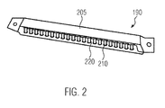
- FIG 2 shows the cleaning means 190 of Figure 1 in more detail.
- the cleaning means 190 comprises a cabinet 205 comprising openings (apertures) 210.
- the openings 210 may be in fluid communication with a tube that is connected to a fan (not shown in Figure 2 ) such that air can be expelled by the fan through the openings 210 during cleaning operation.
- the tube may be connected to a vacuum means that is configured for sucking air and dirt (dust) accumulated on and around the faders 153, etc., shown in Figure 1 through the openings 210.
- a fan may be used for expelling air through the openings towards the faders 153 when operated with, for example, 10000 to 20000 rounds per minute, in one rotational direction and it may be used to suck in air and dirt (dust) accumulated on and around the faders 153 through the openings 210 of the cabinet 205 when operated with, for example, 10000 to 20000 rounds per minute, in the other rotational direction.
- a liquid fluid may be pumped through the openings 210 towards the faders 153.
- the liquid fluid may comprise an alcoholic solution.
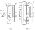
- FIG 3 illustrates another example for an audio mixer 300 in accordance with the present invention.
- the audio mixer 300 comprises a fader 310.
- the fader 310 comprises a fader knob 320 and a fader slot 330.
- an LED strip 340 indicating settings of the audio mixer 300 is arranged on a top surface of a housing 350 of the audio mixer 300 neighbored to the fader 310.
- a cabinet 360 of a cleaning means is arranged parallel to a longitudinal (up-down direction in Figure 3 ) axis of the fader 310 and neighbored to the fader 310.
- the openings 370 of the cabinet 360 are in fluid communication with a tube 380 that is connected to both a fan 390 and a pumping means 395 including a tank.
- the pumping means 395 is configured for pumping a cleaning liquid from the tank through the tube 380 and the openings 370 of the cabinet 360 towards the fader 310.
- Both the pumping means 395 and the fan 390 can be arranged in an interior of the housing 350 of the audio mixer 300 beneath the top surface of the housing 350.
- the fan 390 can be a fan that when being operated with, for example, 10000 to 20000 rounds per minute, in one rotational direction can be used to expel air through the openings 370 of the cabinet 330 in order to remove dirt (dust) accumulated on and/or around and/or below the fader 310 or when operated with, for example, 10000 to 20000 rounds per minute, in the other rotational direction to suck in air and dirt (dust) accumulated on and/or around the fader 310 through the openings 370 of the cabinet 330.
- a cleaning liquid may be supplied to the fader 310 and/or the surrounding of the same by means of the pumping means 395 in order to facilitate the cleaning process.
- the cleaning device may, in principle, be also configured to allow for cleaning of the LED strip 340.
- FIG 4 illustrates an alternative example for an audio mixer 400 in accordance with the present invention.
- the audio mixer 400 comprises a fader 410.
- the fader 410 comprises a fader knob 420 and a fader slot 430.
- an LED strip 440 indicating settings of the audio mixer 400 is arranged on a top surface of a housing 450 of the audio mixer 400 neighbored to the fader 410.
- two cabinets 460 of a cleaning means are arranged perpendicular to a longitudinal (up-down direction in Figure 4 ) axis of the fader 410 and neighbored to the fader 410.
- the two cabinets 460 are arranged at the top and bottom of the fader 410, respectively.
- the openings 470 of the cabinet 460 are in fluid communication with a tube 480 that is connected to both a fan 490 and a pumping means 495 including a tank.
- the pumping means 495 is configured for pumping a cleaning liquid from the tank through the tube 480 and the openings 470 of the cabinet 460 towards the fader 410.
- Both the pumping means 495 and the fan 490 can be arranged in an interior of the housing 450 of the audio mixer 400 beneath the top surface of the housing 450.
- the fan 490 can be a fan that when being operated with, for example, 10000 to 20000 rounds per minute, in one rotational direction can be used to expel air through the openings 470 of the cabinet 430 in order to remove dirt (dust) accumulated on and/or around and/or below the fader 410 or when operated with, for example, 10000 to 20000 rounds per minute, in the other rotational direction to suck in air and dirt (dust) accumulated on and/or around the fader 410 through the openings 470 of the cabinet 430.
- a cleaning liquid may be supplied to the fader 410 and/or the surrounding of the same by means of the pumping means 495 in order to facilitate the cleaning process.
- the cleaning device may, in principle, be also configured to allow for cleaning of the LED strip 440.
Landscapes
- Engineering & Computer Science (AREA)
- Signal Processing (AREA)
- Circuit For Audible Band Transducer (AREA)
- Amplifiers (AREA)
Description
- The present invention relates to an audio mixer, in particular, configured for routing and changing the level, timbre (tone color) and/or dynamics of different audio signals, and comprising a fader usable for fading.
- Audio mixers (mixing consoles) are used in audio systems for applications that may include multi-track recording, broadcast, post production, live sound reinforcement and stage monitoring. The audio mixers may receive multiple sound signals from multiple sound sources across various channels. The sound signals from microphones, electronic musical instruments or other sound sources enter the audio mixer, which amplifies the signals from the sound sources as needed. The audio mixer allows the operator to mix, equalize, and add effects to the signals according to the requirements of the installation. The operator controls the different function of the audio mixing console using a plurality of control elements often configured as faders. Different features of a sound signal may be controlled using the faders. The number of desired features may be large, which corresponds to a large number of faders being mounted on a console.
- However, in the course of the operation of the faders dirt is accumulated that negatively affects the fading performance. For example, dust may stick to the fader knobs/buttons and to the tracks/slots provided for sliding movement of the fader knobs/buttons. A dirty audio mixer may heavily hamper the resulting sound quality. Moreover, dirt may drastically shorten the overall lifetime of the audio mixer.
- Therefore, it is an object of the present application to provide means for enhancing cleanliness and lifetime of an audio mixer.
- The following presents a simplified summary of the disclosure in order to provide a basic understanding of some aspects of the disclosure. This summary is not an exhaustive overview of the disclosure. It is not intended to identify key or critical elements of the disclosure or to delineate the scope of the disclosure. Its sole purpose is to present some concepts in a simplified form as a prelude to the more detailed description that is discussed later.
- In view of the above-mentioned problems, in the present invention it is provided an audio mixer (audio mixing console), comprising a housing (or console), a fader (in fact, the audio mixer may comprise a large number of faders) arranged on and/or in a top surface of the housing, a cleaning means arranged at least partially on the top surface of the housing and configured for cleaning the fader. The fader may comprise a fader knob or a fader button and a track or slot formed in and/or on the top surface of the housing wherein the fader knob or the fader button is moveable on or in the track or slot.
- By providing the cleaning means as part of the audio mixer for cleaning the fader dirt (dust, debris) can be reliably removed and the audio mixer can be maintained in a clean state thereby significantly enhancing the reliability of operation and the life time of the audio mixer.
- The cleaning means may comprise a cabinet comprising openings for expelling a liquid (gas and/or liquid) towards the fader or sucking material from the fader. Thereby, dirt can reliably be removed in a convenient manner.
- According to an embodiment the cleaning means comprises a fan configured for expelling air through the openings of the cabinet towards the fader. The fan may be positioned in an interior of the housing of the audio mixer such that it can expel the air through the openings of the cabinet. By this embodiment a relatively cheap and reliable realization of the cleaning process can be provided.
- According to an alternative embodiment, the cleaning means comprises a pumping device and a nozzle configured for expelling a cleaning liquid (for example, comprising alcohol) through the openings of the cabinet. The cleaning means or the audio mixer, in this case, may further comprise a tank configured for storing the liquid and connected to the pumping device and arranged in an interior of the cabinet of the cleaning means or the housing of the audio mixer. This embodiment can be combined with the one related to the fan expelling air through the openings of the cabinet.
- The above-described audio mixer may alternatively or additionally comprises comprising a vacuum means configured to suck dirt and air from the fader, in particular, through the above-mentioned openings of the cabinet of the cleaning means.
- In all of the above-described examples of the inventive audio mixer the cabinet of the cleaning means may be arranged parallel or perpendicular to a longitudinal axis of the fader.
- Moreover, in all of the above-described examples of the inventive audio mixer the audio mixer may comprise additionally display panel for displaying settings of the audio mixer and allowing further control of the same. In this case, the cleaning means may be configured arranged not only to clean the fader but also the display means. This is particularly advantageous if the display panel represents a touch screen.
- In all of the above-described embodiments, the audio mixer may comprise additionally a dust box for collecting dirt during a cleaning operation of the cleaning means. The dust box can periodically be cleaned.
- Additional features and advantages of the present invention will be described with reference to the drawings. In the description, reference is made to the accompanying figures that are meant to illustrate preferred embodiments of the invention. It is understood that such embodiments do not represent the full scope of the invention.
-
Figure 1 illustrates an embodiment of a system including an audio mixer comprising a cleaning means in accordance with an embodiment of the present invention. -
Figure 2 illustrates a cleaning means of the audio mixer shown inFigure 1 in more detail. -
Figure 3 illustrates another embodiment of an audio mixer according to the present invention comprising a cleaning means arranged parallel to a longitudinal axis of a fader of the audio mixer. -
Figure 4 illustrates another embodiment of an audio mixer according to the present invention comprising a cleaning means arranged perpendicular to a longitudinal axis of a fader of the audio mixer. - While the present disclosure is described with reference to the examples as illustrated in the following detailed description as well as in the drawings, it should be understood that the following detailed description as well as the drawings are not intended to limit the subject matter to the particular illustrative embodiments disclosed, but rather the described illustrative embodiments merely exemplify the various aspects, the scope of which is defined by the appended claims.
- The present disclosure will now be described with reference to the attached figures. Various structures, systems and devices are schematically depicted in the drawings for purposes of explanation only and so as to not obscure the present disclosure with details which are well known to those skilled in the art. Nevertheless, the attached drawings are included to describe and explain illustrative examples of the present disclosure. The words and phrases used herein should be understood and interpreted to have a meaning consistent with the understanding of those words and phrases by those skilled in the relevant art. No special definition of a term or phrase, i.e., a definition that is different from the ordinary or customary meaning as understood by those skilled in the art, is intended to be implied by consistent usage of the term or phrase herein. To the extent that a term or phrase is intended to have a special meaning, i.e., a meaning other than that understood by skilled artisans, such a special definition shall be expressively set forth in the specification in a definitional manner that directly and unequivocally provides the special definition for the term or phrase.
- The present invention relates to an audio mixer for mixing audio signals by means of the operation of faders. According to the invention, the audio mixer comprises a cleaning means for cleaning the faders. The cleaning means is part of the audio mixer and installed at least partially on a top surface of the housing (console) of the audio mixer.
Figure 1 illustrates an example of a system in accordance with an embodiment of the present invention. - The
system 100 may include an audio mixer (audio mixing console) 105 and amobile user device 110 as well as acomputing device 125. Theaudio mixer 105 and themobile device 110 may communicate with one another via a wireless network such as Wi-Fi®, Bluetooth®, ZigBee, cellular networks, ad-hoc wireless networks, etc. Themobile device 110 may be configured to transmit signals wirelessly to theaudio mixer 105. Themobile device 110 may also be configured to generate and transmit audible or audio based information via a device speaker. While theaudio mixer 105 is shown as an entity separate from acomputing device 125, theaudio mixer 105 may include thecomputing device 125. Theaudio mixer 105 is configured to combine various incoming audio signals. Theaudio mixer 105 may further be configured to alter the dynamics of the incoming and outgoing signals for an audio recording system within a recording studio. Theaudio mixer 105 may include a plurality ofports 140. Theseports 140 may provide input signals from various instrument devices 145, for example. - The
audio mixer 105 may also include a transceiver 135 (or wireless access point) for receiving wirelessly transmitted signals. Themobile device 110 is configured to transmit the signal to theaudio mixer 105. Themobile device 110 may be a portable device such as a mobile phone, tablet, personal digital assistant, e-reader, laptop computer, SmartWatch, etc. Theaudio mixer 105 may also include a transmitter (not shown) for transmitting signals back to themobile device 110. Theaudio mixer 105 may include aprocessor 130 to execute a number of functions associated with theaudio mixer 105 disclosed herein. Theprocessor 130 may be configured to analyze the incoming signals. Theprocessor 130 may also instruct the transmitter to transmit certain data and messages. - The
audio mixer 105 may have aconsole display 155. Theconsole display 155 may be an electronic visual display for displaying relevant interfaces to a user of theaudio mixer 105. Thedisplay 155 may be a touch screen and respond to various user inputs such as to a user's finger, stylus, etc. Thedisplay 155 may be a liquid crystal display (LCD), plasma panel, light emitting diode (LED) display, etc. Thedisplay 155 may display information and facilitate the use of theaudio mixer 105 by a user. - Additionally or alternatively, the
audio mixer 105 may have adisplay strip 115. The display strip, similar to theconsole display 155, may be an electronic visual display. Thedisplay strip 115 may be arranged abovefaders 153 arranged on a top surface of theaudio mixer 105 and may be configured to display labels for each of the channels associated with thefaders 153. For example, a separate textual label may be associated with each of thefaders 153 to allow for easy identification of the fader controls. Thefaders 153 may represent variable resistances or potentiometers. The faders may be either analogue faders directly controlling the variable resistances or digital numerically controlling theprocessor 130. - One or
more microphones 175 may be generally coupled to theaudio mixer 105 and may receive the emitted audio from themobile device 110. The emitted audio sounds may include encoded signals identifying alphanumeric characters which indicate label information to theaudio mixer 105. An example signal may include a frequency-shift keying (FSK) signal. The encoded signal, once received from themicrophone 175 and decoded at theprocessor 130, may represent the label (for example, "guitar", "bass", "vocal", etc.) to be associated with the input. The emitted sounds may also include non-coded audio signals which also indicate label information to theaudio mixer 105. These audio signals may be emitted when themobile device 110 is within a predetermined distance from themicrophone 175. A non-coded signal may be a unique tone such as, for example, a 520 Hz sine wave. - A
computing device 125 may be in communication with theaudio mixer 105 via a wireless or hardwired connection. Thecomputing device 125 may include a processor (not shown) and be configured to facilitate sound recording including the adjustment of channels in theaudio mixer 105. At least one monitor 170 (or speaker 170) may also be in communication with theaudio mixer 105. Themonitor 170 may be a speaker for audibly generating the mixed audio signal by theaudio mixer 105. Based on the sound emitted from themonitor 170, a user may adjust the audio signal using theaudio mixer 105 accordingly. Although not shown, additional devices such as amplifiers may be in communication with themonitor 170. - As noted above, any number of microphones 175 (or sensors) may be in communication with the
audio mixer 105. Awire 180 may electrically couple eachmicrophone 175 to theports 140 of theaudio mixer 105. Themicrophones 175 may be positioned near a corresponding instrument device 145a, 145b, 145c, 145d to receive an audio output from the instrument device 145. Eachmicrophone 175 may transmit a signal representing the audio output from one of the instrument devices 145a, 145b, 145c, 145d to theaudio mixer 105. At least one of themicrophones 175 may be arranged to receive a vocal input signal from a vocalist. In one example, themicrophone 175 may be positioned next to an amplifier of an instrument such as an electric guitar. In another example, the electric guitar may include amicrophone 175 within or on the guitar. In another example, the electric guitar may be coupled directly to aninput port 140 to provide the audio input to theaudio mixer 105. In this case, a separate microphone is not necessary to transmit audio signals from the guitar to the audio mixer 105 (see instrument device 145c). - In an implementation that differs from the one described above to label the
ports 140 of theaudio mixer 105, eachmicrophone 175 may receive and/or transmit a label signal to provide information related to the label for thecorresponding input port 140 to theaudio mixer 105. The label signal may be provided to themicrophone 175 from themobile device 110 prior to themicrophone 175 transmitting an audio signal to theaudio mixer 105. For example, eachmicrophone 175 may include an integrated microphone identification circuit. The circuit may include a receiver for receiving wireless signals from themobile device 110. The receiver of themicrophone 175 may receive a message indicating a label (i.e., label signal) to be associated with the channel for which the microphone is connected. That is, instead of themobile device 110 wirelessly transmitting the label to theaudio mixer 105, the label may be transmitted directly from themicrophone 175. Additionally, the circuit may be configured to transmit an identification tone to theaudio mixer 105. Theaudio mixer 105 may receive an encoded tone and identify the channel it was received on. Theaudio mixer 105 may also decode the tone to retrieve the textual label that is to be associated with the channel. Additionally or alternatively, themicrophone 175 may include a built-in circuit having a switch (e.g., radio frequency switch) that when pressed or flipped, may cause an identification tone (i.e., audio signal) to be sent to theaudio mixer 105 via thewire 180. This tone may identify the microphone model and the channel to which it is connected. Themobile device 110 may then transmit the label signal to the microphone circuit or transmit the label signal directly to theaudio mixer 105. - Additionally or alternatively, the
audio mixer 105 may interpret the received audio signal. For example, the audio signal may include an identification tone, or the audio signal may include a tone indicative of one of the instrument devices 145a, 145b, 145c, 145d associated with the microphone (e.g., the signal may represent a drum snare). Theaudio mixer 105 may be capable of recognizing the audio signal as that of a drum snare and may in turn associate the appropriate label (e.g., "Drums"). - The instrument devices 145a-d may include various instruments for recording music. In the examples shown, a drum 145a, keyboard 145b, guitar 145c and microphone 145d may be included. Other instruments or sound emitting devices may also be included. These may include percussion instruments (e.g., xylophone, triangle, wood blocks, clapping sticks, etc.); wind instruments (e.g., accordion, horns, bassoon, clarinet, harmonica, organ, saxophone, trumpet, etc.); or string instruments (e.g., banjo, violin, cello, guitars, harp, etc.). The instrument devices 145a, 145b, 145c, 145d may be configured to emit a sound which may be picked up by the associated
microphone 175. Themicrophone 175 may then transmit an electronic signal representing that sound to theaudio mixer 105. Themicrophones 175 may be in communication via a cord orwire 180. Thewire 180 may be connected to theaudio mixer 105 at aninput port 140. - As shown in
Figure 1 according to the invention theaudio mixer 105 is provided with a cleaning means 190 being part of theaudio mixer 105. The cleaning means 190 is arranged on and/or in a top surface of a housing of theaudio mixer 105 and serves for cleaning at least a number offaders 153. A number of cleaning means 190 similar to the one shown inFigure 1 may be provided for cleaning a plurality or all of thefaders 153 and, possibly, also for cleaning other elements as, for example, thedisplay 155. - The cleaning means 190 may be operated manually, for example, by pressing a corresponding button, by a user of the
system 100 or theaudio mixer 105. Additionally or alternatively the cleaning means 190 may be operated automatically, for example, controlled by theprocessor 130. For example, theprocessor 130 may be programmed to initiate operation of the cleaning means 190 at pre-determined time intervals. Moreover, it may be implemented that the cleaning operation starts every time theaudio mixer 105 is newly started. Proper operation of the cleaning means may be optically indicated, for example, by lightening an LED. Adust box 193 may be provided in fluid communication with the cleaning means 190 for collecting dirt incurring during cleaning operation performed by the cleaning means 190. - Furthermore, a sensor means 195, for example, an optical sensor means 195, may be provided for detecting dirt. The sensor means 195 may be connected to the
processor 130 in order to supply a detection signal to the same. If dirt of some predetermined degree is detected by the sensor means 195, automatically cleaning operation of the cleaning means 190 may be initiated by theprocessor 130 in response to reception of the corresponding detection signal supplied by the sensor means 195. -
Figure 2 shows the cleaning means 190 ofFigure 1 in more detail. As shown inFigure 2 the cleaning means 190 comprises acabinet 205 comprising openings (apertures) 210. Theopenings 210 may be in fluid communication with a tube that is connected to a fan (not shown inFigure 2 ) such that air can be expelled by the fan through theopenings 210 during cleaning operation. Alternatively, the tube may be connected to a vacuum means that is configured for sucking air and dirt (dust) accumulated on and around thefaders 153, etc., shown inFigure 1 through theopenings 210. For example, a fan may be used for expelling air through the openings towards thefaders 153 when operated with, for example, 10000 to 20000 rounds per minute, in one rotational direction and it may be used to suck in air and dirt (dust) accumulated on and around thefaders 153 through theopenings 210 of thecabinet 205 when operated with, for example, 10000 to 20000 rounds per minute, in the other rotational direction. Moreover, a liquid fluid may be pumped through theopenings 210 towards thefaders 153. The liquid fluid may comprise an alcoholic solution. -
Figure 3 illustrates another example for anaudio mixer 300 in accordance with the present invention. Theaudio mixer 300 comprises afader 310. Thefader 310 comprises afader knob 320 and afader slot 330. Moreover, anLED strip 340 indicating settings of theaudio mixer 300 is arranged on a top surface of ahousing 350 of theaudio mixer 300 neighbored to thefader 310. In addition, acabinet 360 of a cleaning means is arranged parallel to a longitudinal (up-down direction inFigure 3 ) axis of thefader 310 and neighbored to thefader 310. - The
openings 370 of thecabinet 360 are in fluid communication with atube 380 that is connected to both afan 390 and a pumping means 395 including a tank. The pumping means 395 is configured for pumping a cleaning liquid from the tank through thetube 380 and theopenings 370 of thecabinet 360 towards thefader 310. Both the pumping means 395 and thefan 390 can be arranged in an interior of thehousing 350 of theaudio mixer 300 beneath the top surface of thehousing 350. Thefan 390 can be a fan that when being operated with, for example, 10000 to 20000 rounds per minute, in one rotational direction can be used to expel air through theopenings 370 of thecabinet 330 in order to remove dirt (dust) accumulated on and/or around and/or below thefader 310 or when operated with, for example, 10000 to 20000 rounds per minute, in the other rotational direction to suck in air and dirt (dust) accumulated on and/or around thefader 310 through theopenings 370 of thecabinet 330. Before operation of the fan, a cleaning liquid may be supplied to thefader 310 and/or the surrounding of the same by means of the pumping means 395 in order to facilitate the cleaning process. The cleaning device may, in principle, be also configured to allow for cleaning of theLED strip 340. -
Figure 4 illustrates an alternative example for anaudio mixer 400 in accordance with the present invention. Theaudio mixer 400 comprises afader 410. Thefader 410 comprises afader knob 420 and afader slot 430. Moreover, anLED strip 440 indicating settings of theaudio mixer 400 is arranged on a top surface of ahousing 450 of theaudio mixer 400 neighbored to thefader 410. In addition, twocabinets 460 of a cleaning means are arranged perpendicular to a longitudinal (up-down direction inFigure 4 ) axis of thefader 410 and neighbored to thefader 410. The twocabinets 460 are arranged at the top and bottom of thefader 410, respectively. - The
openings 470 of thecabinet 460 are in fluid communication with atube 480 that is connected to both afan 490 and a pumping means 495 including a tank. The pumping means 495 is configured for pumping a cleaning liquid from the tank through thetube 480 and theopenings 470 of thecabinet 460 towards thefader 410. Both the pumping means 495 and thefan 490 can be arranged in an interior of thehousing 450 of theaudio mixer 400 beneath the top surface of thehousing 450. Thefan 490 can be a fan that when being operated with, for example, 10000 to 20000 rounds per minute, in one rotational direction can be used to expel air through theopenings 470 of thecabinet 430 in order to remove dirt (dust) accumulated on and/or around and/or below thefader 410 or when operated with, for example, 10000 to 20000 rounds per minute, in the other rotational direction to suck in air and dirt (dust) accumulated on and/or around thefader 410 through theopenings 470 of thecabinet 430. Before operation of the fan, a cleaning liquid may be supplied to thefader 410 and/or the surrounding of the same by means of the pumping means 495 in order to facilitate the cleaning process. The cleaning device may, in principle, be also configured to allow for cleaning of theLED strip 440. - All previously discussed embodiments are not intended as limitations but serve as examples illustrating features and advantages of the invention. It is to be understood that some or all of the above described features and embodiments can also be combined in different ways.
Claims (14)
- An audio mixer, comprising
a housing;
a fader arranged on and/or in a top surface of the housing;
a cleaning means arranged at least partially on the top surface of the housing and configured for cleaning the fader. - The audio mixer according to claim 1, wherein the fader comprises a fader knob or a fader button and a fader track or fader slot formed in and/or on the top surface of the housing and wherein the fader knob or the fader button is moveable on or in the track or slot.
- The audio mixer according to claim 1 or 2, wherein the cleaning means comprises a cabinet comprising openings for expelling a liquid towards the fader or sucking material from the fader.
- The audio mixer according to claim 3, wherein the liquid is a gas and/or a fluid.
- The audio mixer according to claim 3, wherein the cleaning means comprises a fan configured for expelling air through the openings of the cabinet.
- The audio mixer according to claim 5, wherein the fan is positioned in an interior of the housing.
- The audio mixer according to claim 3, 5 or 6, wherein the cleaning means comprises a pumping device and a nozzle configured for expelling a liquid through the openings of the cabinet.
- The audio mixer according to claim 7, further comprising a tank configured for storing the liquid and connected to the pumping device and arranged in an interior of the cabinet of the cleaning means or the housing of the audio mixer.
- The audio mixer according to claim 3, 5, 6, 7 or 8, further comprising a vacuum means configured to suck dirt and air from the fader.
- The audio mixer according to one of the claims 3 to 9, wherein the cabinet of the cleaning means is arranged parallel to a longitudinal axis of the fader.
- The audio mixer according to one of the claims 3 to 9, wherein the cabinet of the cleaning means is arranged perpendicular to a longitudinal axis of the fader.
- The audio mixer according to one of the preceding claims, further comprising a display panel and wherein the cleaning means is configured for cleaning the display panel.
- The audio mixer according to one of the preceding claims, further comprising a dust box configured for collecting dirt.
- The audio mixer according to one of the preceding claims, further comprising a processor configured for automatically initiating operation of the cleaning means at predetermined time intervals and/or at start of operation of the audio mixer and/or upon detection of dirt on and/or on the top surface of the housing sin the neighborhood of the fader.
Priority Applications (1)
| Application Number | Priority Date | Filing Date | Title |
|---|---|---|---|
| EP16178195.0A EP3267601B1 (en) | 2016-07-06 | 2016-07-06 | Audio mixer |
Applications Claiming Priority (1)
| Application Number | Priority Date | Filing Date | Title |
|---|---|---|---|
| EP16178195.0A EP3267601B1 (en) | 2016-07-06 | 2016-07-06 | Audio mixer |
Publications (2)
| Publication Number | Publication Date |
|---|---|
| EP3267601A1 true EP3267601A1 (en) | 2018-01-10 |
| EP3267601B1 EP3267601B1 (en) | 2019-10-02 |
Family
ID=56372779
Family Applications (1)
| Application Number | Title | Priority Date | Filing Date |
|---|---|---|---|
| EP16178195.0A Active EP3267601B1 (en) | 2016-07-06 | 2016-07-06 | Audio mixer |
Country Status (1)
| Country | Link |
|---|---|
| EP (1) | EP3267601B1 (en) |
Citations (2)
| Publication number | Priority date | Publication date | Assignee | Title |
|---|---|---|---|---|
| US20080192008A1 (en) * | 2007-02-09 | 2008-08-14 | Denny Lee Jaeger | Magnetically coupled fader controller for electronic display |
| US20100188822A1 (en) * | 2009-01-23 | 2010-07-29 | Yamaha Corporation | Casing structure for sound adjusting apparatus |
-
2016
- 2016-07-06 EP EP16178195.0A patent/EP3267601B1/en active Active
Patent Citations (2)
| Publication number | Priority date | Publication date | Assignee | Title |
|---|---|---|---|---|
| US20080192008A1 (en) * | 2007-02-09 | 2008-08-14 | Denny Lee Jaeger | Magnetically coupled fader controller for electronic display |
| US20100188822A1 (en) * | 2009-01-23 | 2010-07-29 | Yamaha Corporation | Casing structure for sound adjusting apparatus |
Also Published As
| Publication number | Publication date |
|---|---|
| EP3267601B1 (en) | 2019-10-02 |
Similar Documents
| Publication | Publication Date | Title |
|---|---|---|
| US9500515B2 (en) | Multifunctional wearable audio-sensing electronic device | |
| US9838146B2 (en) | Apparatus for labeling inputs of an audio mixing console system | |
| US20160372097A1 (en) | Wireless musical instrument tuner | |
| EP3018847B1 (en) | Apparatus for labeling inputs of an audio mixing console system | |
| EP2770498A1 (en) | Method of retrieving processing properties and audio processing system | |
| JP2001154672A (en) | Communication device and storage medium | |
| CN207491185U (en) | Intelligent power output amplification component | |
| EP3267601B1 (en) | Audio mixer | |
| JP6733781B2 (en) | Audio equipment | |
| US10535331B2 (en) | System, apparatus and methods for musical instrument amplifier | |
| CN113728377B (en) | Tuning device | |
| US10540951B2 (en) | Musical instrument amplifier | |
| US20070137467A1 (en) | Portable media player | |
| US20160112799A1 (en) | Acoustic system, acoustic system control device, and acoustic system control method | |
| JP5292129B2 (en) | Microphone transmission signal interference prevention system | |
| US20250176086A1 (en) | Multi-modal programmable sound-responsive lighting unit and application | |
| JP4451364B2 (en) | Karaoke device that repeats preludes at the time of singing | |
| KR100687693B1 (en) | Mobile terminal with dual performance | |
| JP2001274869A (en) | mobile phone | |
| JP7073709B2 (en) | Electronic devices, control methods and programs for electronic devices, and audio systems | |
| JP2004053779A (en) | Electronic tuner | |
| JP4451365B2 (en) | A karaoke device that stops playing music while fading out | |
| US9681230B2 (en) | Acoustic system, output device, and acoustic system control method | |
| JP2010021971A (en) | Cellular phone with electronic musical instrument | |
| KR20150098148A (en) | Guitar |
Legal Events
| Date | Code | Title | Description |
|---|---|---|---|
| PUAI | Public reference made under article 153(3) epc to a published international application that has entered the european phase |
Free format text: ORIGINAL CODE: 0009012 |
|
| STAA | Information on the status of an ep patent application or granted ep patent |
Free format text: STATUS: THE APPLICATION HAS BEEN PUBLISHED |
|
| AK | Designated contracting states |
Kind code of ref document: A1 Designated state(s): AL AT BE BG CH CY CZ DE DK EE ES FI FR GB GR HR HU IE IS IT LI LT LU LV MC MK MT NL NO PL PT RO RS SE SI SK SM TR |
|
| AX | Request for extension of the european patent |
Extension state: BA ME |
|
| STAA | Information on the status of an ep patent application or granted ep patent |
Free format text: STATUS: REQUEST FOR EXAMINATION WAS MADE |
|
| 17P | Request for examination filed |
Effective date: 20180627 |
|
| RBV | Designated contracting states (corrected) |
Designated state(s): AL AT BE BG CH CY CZ DE DK EE ES FI FR GB GR HR HU IE IS IT LI LT LU LV MC MK MT NL NO PL PT RO RS SE SI SK SM TR |
|
| STAA | Information on the status of an ep patent application or granted ep patent |
Free format text: STATUS: EXAMINATION IS IN PROGRESS |
|
| 17Q | First examination report despatched |
Effective date: 20180906 |
|
| GRAP | Despatch of communication of intention to grant a patent |
Free format text: ORIGINAL CODE: EPIDOSNIGR1 |
|
| STAA | Information on the status of an ep patent application or granted ep patent |
Free format text: STATUS: GRANT OF PATENT IS INTENDED |
|
| INTG | Intention to grant announced |
Effective date: 20190522 |
|
| GRAS | Grant fee paid |
Free format text: ORIGINAL CODE: EPIDOSNIGR3 |
|
| GRAA | (expected) grant |
Free format text: ORIGINAL CODE: 0009210 |
|
| STAA | Information on the status of an ep patent application or granted ep patent |
Free format text: STATUS: THE PATENT HAS BEEN GRANTED |
|
| AK | Designated contracting states |
Kind code of ref document: B1 Designated state(s): AL AT BE BG CH CY CZ DE DK EE ES FI FR GB GR HR HU IE IS IT LI LT LU LV MC MK MT NL NO PL PT RO RS SE SI SK SM TR |
|
| REG | Reference to a national code |
Ref country code: GB Ref legal event code: FG4D |
|
| REG | Reference to a national code |
Ref country code: CH Ref legal event code: EP Ref country code: AT Ref legal event code: REF Ref document number: 1187369 Country of ref document: AT Kind code of ref document: T Effective date: 20191015 |
|
| REG | Reference to a national code |
Ref country code: DE Ref legal event code: R096 Ref document number: 602016021535 Country of ref document: DE |
|
| REG | Reference to a national code |
Ref country code: IE Ref legal event code: FG4D |
|
| REG | Reference to a national code |
Ref country code: NL Ref legal event code: MP Effective date: 20191002 |
|
| REG | Reference to a national code |
Ref country code: LT Ref legal event code: MG4D |
|
| REG | Reference to a national code |
Ref country code: AT Ref legal event code: MK05 Ref document number: 1187369 Country of ref document: AT Kind code of ref document: T Effective date: 20191002 |
|
| PG25 | Lapsed in a contracting state [announced via postgrant information from national office to epo] |
Ref country code: PT Free format text: LAPSE BECAUSE OF FAILURE TO SUBMIT A TRANSLATION OF THE DESCRIPTION OR TO PAY THE FEE WITHIN THE PRESCRIBED TIME-LIMIT Effective date: 20200203 Ref country code: FI Free format text: LAPSE BECAUSE OF FAILURE TO SUBMIT A TRANSLATION OF THE DESCRIPTION OR TO PAY THE FEE WITHIN THE PRESCRIBED TIME-LIMIT Effective date: 20191002 Ref country code: AT Free format text: LAPSE BECAUSE OF FAILURE TO SUBMIT A TRANSLATION OF THE DESCRIPTION OR TO PAY THE FEE WITHIN THE PRESCRIBED TIME-LIMIT Effective date: 20191002 Ref country code: NL Free format text: LAPSE BECAUSE OF FAILURE TO SUBMIT A TRANSLATION OF THE DESCRIPTION OR TO PAY THE FEE WITHIN THE PRESCRIBED TIME-LIMIT Effective date: 20191002 Ref country code: SE Free format text: LAPSE BECAUSE OF FAILURE TO SUBMIT A TRANSLATION OF THE DESCRIPTION OR TO PAY THE FEE WITHIN THE PRESCRIBED TIME-LIMIT Effective date: 20191002 Ref country code: PL Free format text: LAPSE BECAUSE OF FAILURE TO SUBMIT A TRANSLATION OF THE DESCRIPTION OR TO PAY THE FEE WITHIN THE PRESCRIBED TIME-LIMIT Effective date: 20191002 Ref country code: LT Free format text: LAPSE BECAUSE OF FAILURE TO SUBMIT A TRANSLATION OF THE DESCRIPTION OR TO PAY THE FEE WITHIN THE PRESCRIBED TIME-LIMIT Effective date: 20191002 Ref country code: ES Free format text: LAPSE BECAUSE OF FAILURE TO SUBMIT A TRANSLATION OF THE DESCRIPTION OR TO PAY THE FEE WITHIN THE PRESCRIBED TIME-LIMIT Effective date: 20191002 Ref country code: BG Free format text: LAPSE BECAUSE OF FAILURE TO SUBMIT A TRANSLATION OF THE DESCRIPTION OR TO PAY THE FEE WITHIN THE PRESCRIBED TIME-LIMIT Effective date: 20200102 Ref country code: GR Free format text: LAPSE BECAUSE OF FAILURE TO SUBMIT A TRANSLATION OF THE DESCRIPTION OR TO PAY THE FEE WITHIN THE PRESCRIBED TIME-LIMIT Effective date: 20200103 Ref country code: LV Free format text: LAPSE BECAUSE OF FAILURE TO SUBMIT A TRANSLATION OF THE DESCRIPTION OR TO PAY THE FEE WITHIN THE PRESCRIBED TIME-LIMIT Effective date: 20191002 Ref country code: NO Free format text: LAPSE BECAUSE OF FAILURE TO SUBMIT A TRANSLATION OF THE DESCRIPTION OR TO PAY THE FEE WITHIN THE PRESCRIBED TIME-LIMIT Effective date: 20200102 |
|
| PG25 | Lapsed in a contracting state [announced via postgrant information from national office to epo] |
Ref country code: RS Free format text: LAPSE BECAUSE OF FAILURE TO SUBMIT A TRANSLATION OF THE DESCRIPTION OR TO PAY THE FEE WITHIN THE PRESCRIBED TIME-LIMIT Effective date: 20191002 Ref country code: HR Free format text: LAPSE BECAUSE OF FAILURE TO SUBMIT A TRANSLATION OF THE DESCRIPTION OR TO PAY THE FEE WITHIN THE PRESCRIBED TIME-LIMIT Effective date: 20191002 Ref country code: IS Free format text: LAPSE BECAUSE OF FAILURE TO SUBMIT A TRANSLATION OF THE DESCRIPTION OR TO PAY THE FEE WITHIN THE PRESCRIBED TIME-LIMIT Effective date: 20200224 Ref country code: CZ Free format text: LAPSE BECAUSE OF FAILURE TO SUBMIT A TRANSLATION OF THE DESCRIPTION OR TO PAY THE FEE WITHIN THE PRESCRIBED TIME-LIMIT Effective date: 20191002 |
|
| PG25 | Lapsed in a contracting state [announced via postgrant information from national office to epo] |
Ref country code: AL Free format text: LAPSE BECAUSE OF FAILURE TO SUBMIT A TRANSLATION OF THE DESCRIPTION OR TO PAY THE FEE WITHIN THE PRESCRIBED TIME-LIMIT Effective date: 20191002 |
|
| REG | Reference to a national code |
Ref country code: DE Ref legal event code: R097 Ref document number: 602016021535 Country of ref document: DE |
|
| PG2D | Information on lapse in contracting state deleted |
Ref country code: IS |
|
| PG25 | Lapsed in a contracting state [announced via postgrant information from national office to epo] |
Ref country code: EE Free format text: LAPSE BECAUSE OF FAILURE TO SUBMIT A TRANSLATION OF THE DESCRIPTION OR TO PAY THE FEE WITHIN THE PRESCRIBED TIME-LIMIT Effective date: 20191002 Ref country code: RO Free format text: LAPSE BECAUSE OF FAILURE TO SUBMIT A TRANSLATION OF THE DESCRIPTION OR TO PAY THE FEE WITHIN THE PRESCRIBED TIME-LIMIT Effective date: 20191002 Ref country code: DK Free format text: LAPSE BECAUSE OF FAILURE TO SUBMIT A TRANSLATION OF THE DESCRIPTION OR TO PAY THE FEE WITHIN THE PRESCRIBED TIME-LIMIT Effective date: 20191002 Ref country code: IS Free format text: LAPSE BECAUSE OF FAILURE TO SUBMIT A TRANSLATION OF THE DESCRIPTION OR TO PAY THE FEE WITHIN THE PRESCRIBED TIME-LIMIT Effective date: 20200202 |
|
| PLBE | No opposition filed within time limit |
Free format text: ORIGINAL CODE: 0009261 |
|
| STAA | Information on the status of an ep patent application or granted ep patent |
Free format text: STATUS: NO OPPOSITION FILED WITHIN TIME LIMIT |
|
| PG25 | Lapsed in a contracting state [announced via postgrant information from national office to epo] |
Ref country code: SK Free format text: LAPSE BECAUSE OF FAILURE TO SUBMIT A TRANSLATION OF THE DESCRIPTION OR TO PAY THE FEE WITHIN THE PRESCRIBED TIME-LIMIT Effective date: 20191002 Ref country code: SM Free format text: LAPSE BECAUSE OF FAILURE TO SUBMIT A TRANSLATION OF THE DESCRIPTION OR TO PAY THE FEE WITHIN THE PRESCRIBED TIME-LIMIT Effective date: 20191002 Ref country code: IT Free format text: LAPSE BECAUSE OF FAILURE TO SUBMIT A TRANSLATION OF THE DESCRIPTION OR TO PAY THE FEE WITHIN THE PRESCRIBED TIME-LIMIT Effective date: 20191002 |
|
| 26N | No opposition filed |
Effective date: 20200703 |
|
| PG25 | Lapsed in a contracting state [announced via postgrant information from national office to epo] |
Ref country code: SI Free format text: LAPSE BECAUSE OF FAILURE TO SUBMIT A TRANSLATION OF THE DESCRIPTION OR TO PAY THE FEE WITHIN THE PRESCRIBED TIME-LIMIT Effective date: 20191002 |
|
| PG25 | Lapsed in a contracting state [announced via postgrant information from national office to epo] |
Ref country code: MC Free format text: LAPSE BECAUSE OF FAILURE TO SUBMIT A TRANSLATION OF THE DESCRIPTION OR TO PAY THE FEE WITHIN THE PRESCRIBED TIME-LIMIT Effective date: 20191002 |
|
| REG | Reference to a national code |
Ref country code: CH Ref legal event code: PL |
|
| GBPC | Gb: european patent ceased through non-payment of renewal fee |
Effective date: 20200706 |
|
| REG | Reference to a national code |
Ref country code: BE Ref legal event code: MM Effective date: 20200731 |
|
| PG25 | Lapsed in a contracting state [announced via postgrant information from national office to epo] |
Ref country code: IE Free format text: LAPSE BECAUSE OF NON-PAYMENT OF DUE FEES Effective date: 20200706 Ref country code: GB Free format text: LAPSE BECAUSE OF NON-PAYMENT OF DUE FEES Effective date: 20200706 Ref country code: FR Free format text: LAPSE BECAUSE OF NON-PAYMENT OF DUE FEES Effective date: 20200731 Ref country code: LU Free format text: LAPSE BECAUSE OF NON-PAYMENT OF DUE FEES Effective date: 20200706 Ref country code: LI Free format text: LAPSE BECAUSE OF NON-PAYMENT OF DUE FEES Effective date: 20200731 Ref country code: CH Free format text: LAPSE BECAUSE OF NON-PAYMENT OF DUE FEES Effective date: 20200731 |
|
| PG25 | Lapsed in a contracting state [announced via postgrant information from national office to epo] |
Ref country code: BE Free format text: LAPSE BECAUSE OF NON-PAYMENT OF DUE FEES Effective date: 20200731 |
|
| PG25 | Lapsed in a contracting state [announced via postgrant information from national office to epo] |
Ref country code: TR Free format text: LAPSE BECAUSE OF FAILURE TO SUBMIT A TRANSLATION OF THE DESCRIPTION OR TO PAY THE FEE WITHIN THE PRESCRIBED TIME-LIMIT Effective date: 20191002 Ref country code: MT Free format text: LAPSE BECAUSE OF FAILURE TO SUBMIT A TRANSLATION OF THE DESCRIPTION OR TO PAY THE FEE WITHIN THE PRESCRIBED TIME-LIMIT Effective date: 20191002 Ref country code: CY Free format text: LAPSE BECAUSE OF FAILURE TO SUBMIT A TRANSLATION OF THE DESCRIPTION OR TO PAY THE FEE WITHIN THE PRESCRIBED TIME-LIMIT Effective date: 20191002 |
|
| PG25 | Lapsed in a contracting state [announced via postgrant information from national office to epo] |
Ref country code: MK Free format text: LAPSE BECAUSE OF FAILURE TO SUBMIT A TRANSLATION OF THE DESCRIPTION OR TO PAY THE FEE WITHIN THE PRESCRIBED TIME-LIMIT Effective date: 20191002 |
|
| P01 | Opt-out of the competence of the unified patent court (upc) registered |
Effective date: 20230527 |
|
| PGFP | Annual fee paid to national office [announced via postgrant information from national office to epo] |
Ref country code: DE Payment date: 20250620 Year of fee payment: 10 |