EP3267498A1 - Group iii nitride semiconductor light emitting element and wafer containing element structure - Google Patents
Group iii nitride semiconductor light emitting element and wafer containing element structure Download PDFInfo
- Publication number
- EP3267498A1 EP3267498A1 EP16761544.2A EP16761544A EP3267498A1 EP 3267498 A1 EP3267498 A1 EP 3267498A1 EP 16761544 A EP16761544 A EP 16761544A EP 3267498 A1 EP3267498 A1 EP 3267498A1
- Authority
- EP
- European Patent Office
- Prior art keywords
- electrode
- mesa
- layer
- edge
- type layer
- Prior art date
- Legal status (The legal status is an assumption and is not a legal conclusion. Google has not performed a legal analysis and makes no representation as to the accuracy of the status listed.)
- Granted
Links
Images



Classifications
-
- H—ELECTRICITY
- H10—SEMICONDUCTOR DEVICES; ELECTRIC SOLID-STATE DEVICES NOT OTHERWISE PROVIDED FOR
- H10H—INORGANIC LIGHT-EMITTING SEMICONDUCTOR DEVICES HAVING POTENTIAL BARRIERS
- H10H20/00—Individual inorganic light-emitting semiconductor devices having potential barriers, e.g. light-emitting diodes [LED]
- H10H20/80—Constructional details
- H10H20/81—Bodies
- H10H20/822—Materials of the light-emitting regions
- H10H20/824—Materials of the light-emitting regions comprising only Group III-V materials, e.g. GaP
- H10H20/825—Materials of the light-emitting regions comprising only Group III-V materials, e.g. GaP containing nitrogen, e.g. GaN
-
- H—ELECTRICITY
- H10—SEMICONDUCTOR DEVICES; ELECTRIC SOLID-STATE DEVICES NOT OTHERWISE PROVIDED FOR
- H10H—INORGANIC LIGHT-EMITTING SEMICONDUCTOR DEVICES HAVING POTENTIAL BARRIERS
- H10H20/00—Individual inorganic light-emitting semiconductor devices having potential barriers, e.g. light-emitting diodes [LED]
- H10H20/80—Constructional details
- H10H20/81—Bodies
- H10H20/811—Bodies having quantum effect structures or superlattices, e.g. tunnel junctions
- H10H20/812—Bodies having quantum effect structures or superlattices, e.g. tunnel junctions within the light-emitting regions, e.g. having quantum confinement structures
-
- H—ELECTRICITY
- H10—SEMICONDUCTOR DEVICES; ELECTRIC SOLID-STATE DEVICES NOT OTHERWISE PROVIDED FOR
- H10H—INORGANIC LIGHT-EMITTING SEMICONDUCTOR DEVICES HAVING POTENTIAL BARRIERS
- H10H20/00—Individual inorganic light-emitting semiconductor devices having potential barriers, e.g. light-emitting diodes [LED]
- H10H20/80—Constructional details
- H10H20/83—Electrodes
- H10H20/831—Electrodes characterised by their shape
-
- H—ELECTRICITY
- H10—SEMICONDUCTOR DEVICES; ELECTRIC SOLID-STATE DEVICES NOT OTHERWISE PROVIDED FOR
- H10H—INORGANIC LIGHT-EMITTING SEMICONDUCTOR DEVICES HAVING POTENTIAL BARRIERS
- H10H20/00—Individual inorganic light-emitting semiconductor devices having potential barriers, e.g. light-emitting diodes [LED]
- H10H20/80—Constructional details
- H10H20/85—Packages
- H10H20/855—Optical field-shaping means, e.g. lenses
Definitions
- the present invention relates to a group III nitride semiconductor luminescence element comprising a luminescence peak wavelength of ultraviolet ray. Particularly, the present invention relates to a technology of preventing the deterioration of the element caused by the current concentration to an edge part of a mesa structure of the luminescence element. Also, the present invention relates to a wafer comprising the constitution of said luminescence element.
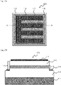
- Fig.7A and Fig.7B show typical schematic structures of a group III nitride semiconductor luminescence element 20.
- Fig.7A is a top view of the element, and Fig.7B shows the cross section at A-A line of Fig.7A .
- the group III nitride semiconductor luminescence element 20 is formed with a laminate (hereinafter, this may be referred as a "laminate semiconductor layer”) comprising on one surface side of a substrate 11, a n-type layer 12, an active layer 13, and a p-type layer 14; and having a mesa structure 15 at a part of the laminate semiconductor layer thereof is known.
- the mesa structure 15 is formed by forming the laminate semiconductor layer comprising on one surface side of the substrate 11, the n-type layer 12, the active layer 13, and the p-type layer, and then removing a part of the laminate structure by etching or so to expose a part of the n-type layer 12.
- a part having a plateau shape (also called as a mesa) including the active layer 13 and the p-type layer is maintained; thereby the mesa structure 15 is formed (see the patent document 1).
- An n-type electrode 16 is formed on the exposed surface of the n-type layer 12, and a p-type electrode 17 is formed at the surface of the p-type layer 14.
- the current runs the pathway having a low resistance (usually the shortest pathway) between the p-type electrode and the n-type electrode, thus the current runs by concentrating at near the edge part of the mesa structure 15 (hereinafter, it will be called as a "mesa edge") close to the n-type electrode and the p-type electrode.
- the current does not flow uniformly to the active layer 13, thus uneven luminescence occurs.
- the current concentrates at the mesa edge, a local heat generation occurs near the mesa edge.
- the deterioration of the luminescence element easily proceeds, and causes the decrease in the luminescence efficiency, increase in the driving voltage, and decrease in the reliability.
- the patent document 2 discloses the ultraviolet semiconductor luminescence element wherein the high resistance layer having higher resistance than the p-type layer or p-electrode is formed in a shape along the shape of p-type layer side at closer side to the n-type electrode on the surface of the p-type layer.
- the high resistance layer when the high resistance layer is formed on the p-type layer close to the mesa edge, the current can be suppressed from concentrating near the mesa edge.
- the resistance between the p-type electrode and the semiconductor layer becomes larger, and the driving voltage becomes larger as well.
- the patent document 3 discloses the semiconductor luminescence element wherein a trench is formed between the p-electrode and the n-electrode.
- a trench is formed between the p-electrode and the n-electrode.
- the length of the current pathway running between the p-electrode and the n-electrode is suppressed from varying; thereby the current is suppressed from concentrating to a particular part.
- the depth of the trench must be deep. If the trench is made deep, the current pathway as a whole becomes longer, and the resistance becomes large, and the driving voltage also becomes large.
- the luminescence element having various shapes and constitution has been proposed, and also there are variety of mesa structures and designs of the electrode shapes.
- the art of forming the high resistance layer and the trench as mentioned in the above will increase the steps for producing the luminescence element, hence it has become difficult to correspond to the various mesa structure and electrodes shape in a timely manner.
- the deep ultraviolet ray luminescence element having the luminescence peak wavelength of 200 to 350 nm is difficult to produce; hence the yield tends to easily decrease. Further, when the current is running, the current tends to concentrate near the mesa edge, thus such part may deteriorate due to the heat or so and the quality tends to be damaged. Thus, the development of the luminescence element capable of suppressing the deterioration caused by the current concentration near the mesa edge was in demand.
- the object of the present invention is to provide the group III nitride semiconductor luminescence element capable to suppress the deterioration of the luminescence element caused by the current flowing between the p-electrode and the n-electrode concentrating near the mesa edge, without increasing the steps for producing the luminescence element, and without excessively increasing the driving voltage.
- the present inventors have speculated that the above object can be attained by regulating the structure of the p-electrode, and has carried out keen examination. Further, the present inventors have found that the above object can be attained by forming the p-electrode by taking certain distance from the edge part of the mesa structure, particularly at the part where the mesa structure is projecting out; thereby the present invention was attained.
- the first invention is a group III nitride semiconductor luminescence element having a mesa structure comprising a n-type layer, a p-type layer, an active layer provided between the n-type layer and the p-type layer, a n-electrode provided on said n-type layer, and a p-electrode provided on said p-type layer; wherein
- the second invention is the group III nitride semiconductor luminescence element as set forth in the first invention, wherein the distance between a projection part of the edge of the mesa structure and the outer peripheral of said p-electrode is 1/3 or more of the scattering length L s .
- the current tends to easily concentrate to the p-electrode part at the projection part of the mesa edge, thus the distance between the projection part of the mesa edge and said peripheral of the p-electrode is preferably within the above mentioned range.
- the third invention is the group III nitride semiconductor luminescence element as set forth in the first invention, wherein the distance between a projection part of the edge of the mesa structure and the outer peripheral of said p-electrode is 12 ⁇ m or more.
- the fourth invention is the group III nitride semiconductor luminescence element as set forth in first to third inventions, wherein the luminescence peak wavelength is 200 to 350 nm.
- the group III nitride semiconductor luminescence element having the luminescence peak wavelength of 200 to 350 nm is difficult to produce, and the improvement of the yield is strongly demanded, thus the present invention is suitable.
- the fifth invention is a wafer including the constitution of a group III nitride semiconductor luminescence element comprising a n-type layer, a p-type layer, an active layer provided between the n-type layer and the p-type layer, a n-electrode provided on said n-type layer, and a p-electrode provided on said p-type layer, wherein the constitution of said group III nitride semiconductor luminescence element is as set forth in said inventions 1 to 4.
- the distance between a part of the mesa edge and the outer peripheral of said p-electrode is set to predetermine value or more, thereby a p-electrode restricted area is provided near the edge part of the mesa structure.
- this p-electrode restricted area the ratio of the p-electrode formed is regulated to be low compared to the mesa part other than this area.
- the quality damage caused by the current concentration near the mesa edge when running the current can be decreased, thus the yield of the luminescence element can be improved.
- the ultraviolet ray emitting element having the luminescence peak wavelength of 200 to 350 nm tends to have decreased yield because it is difficult to produce due to the influence of the composition of each layer, compared to the luminescence element having the luminescence peak wavelength longer than 350 nm, such as for example the luminescence element having the visible light range.
- the present invention can suppress the decrease of the yield which is caused by the local deterioration of the mesa structure; hence it is suited as the ultraviolet ray emitting element having the luminescence peak wavelength of 200 to 350 nm.
- the luminescence element described in below is one example realizing the concept of the present invention, and the present invention is not limited thereto.
- the size, material, shape and relative position or so of the element described in below is merely an example used for describing and the present invention is not to be limited thereto, unless mentioned otherwise.
- the size and the relationship of the position of the members shown in each figure may be exaggerated in order to make the description clear.
- the luminescence range of the light emitted from the group III nitride semiconductor luminescence element of the present invention is not particularly limited. According to the present invention, regardless of the luminescence range, the decrease of the output caused by the deterioration due to the local current concentration in the mesa structure is suppressed, and the yield can be improved.
- the present invention is used for the group III nitride semiconductor luminescence element comprising the luminescence peak wavelength in the visible light range or in the ultraviolet range. More preferably, the present invention is used for the group III nitride semiconductor luminescence element emitting the ultraviolet ray having the luminescence peak wavelength of 200 to 350 nm.
- the group III nitride semiconductor luminescence element having the luminescence peak wavelength of 200 to 350 nm will be mainly discussed.
- the typical group III nitride semiconductor luminescence element 20 comprises a n-electrode 16, and a p-electrode 17, a substrate 11, and a mesa structure 15 (a laminate semiconductor layer) including a n-type layer 12, an active layer 13 and p-type layer 14.
- a non-limiting typical example thereof will be discussed.
- a refraction factor, a transmission factor, and a reflection factor are based on the light having the wavelength of 265 nm. This is because DNA has a maximum absorbance near the wavelength of 265 nm, thus the light having the wavelength of 265 nm is most suited for sterilization, and hence will have high industrial applicability.
- the refraction factor, the transmission factor, and the reflection factor these are values with respect to the light having the wavelength of 265 nm.
- the substrate 11 allows the epitaxial growth of the group III nitride semiconductor luminescence element on the surface, and as long as it is a substrate allowing the ultraviolet ray to transmit through, it is not particularly limited.
- the material used for the substrate 11 for example, sapphire, SiC (silicon carbide), AIN (aluminum nitride), Si (silicon) or so may be mentioned.
- an AIN single crystal substrate using c-plane as a principle plane is preferable.
- the upper limit of the transmission factor of the substrate 11 is preferably 100%; and from the point of the industrial production, it is 80%.
- the transmission factor of the translucent substrate can be regulated by the material, the thickness of the substrate, the crystallinity, and the impurity content.
- the thickness of the substrate 11 is not particularly limited, but preferably it is 30 to 150 ⁇ m, and more preferably 50 to 100 ⁇ m. By setting the thickness of the substrate 11 within the above mentioned range, the transmission factor is improved, and the productivity is improved.
- the thickness of the substrate 11 only needs to satisfy the above mentioned range after the group III nitride semiconductor luminescence element is produced; and the lower face of the substrate may be ground or polished after laminating the laminate semiconductor layer or the electrode on the substrate, thereby the thickness of the substrate may be within the above mentioned range.
- the laminate semiconductor layer (the main part of the element including the mesa structure 15 of Fig.7 ) is formed on the substrate 11 as shown in Fig.7B , and the n-type layer 12, the active layer 13 and the p-type layer 14 (the layer formed of a p-type clad layer and a p-type contact layer) are stacked in this order.
- the impurity is not particularly limited, but preferably Si, Ge, Sn or so may be mentioned. Among these, Si and Ge are preferable.
- the concentration of the impurity is 1.0 x 10 17 cm -3 or more and 5.0 x 10 20 cm -3 or less; and preferably 1.0 x 10 18 cm -3 or more and 5.0 x 10 19 cm -3 or less. By setting the concentration of the impurity within the above range, the crystallinity and the contact characteristic of the n-type layer improves. Such n-type layer may be produced by MOCVD method.
- the refraction factor of the n-type layer is not particularly limited, but it is 1.5 to 3.0.
- the refraction factor may be regulated by the composition of the n-type layer.
- the thickness of the n-type layer is 100 nm or more and 10000 nm or less, and preferably 500 nm or more and 3000 nm or less. By having the thickness of the n-type layer within the above range, the crystallinity and the conductivity of the n-type layer improves.
- the group III nitride semiconductor luminescence element 20 may comprise a buffer layer including the group III nitride semiconductor having the composition same or similar to AIN or the above mentioned n-type layer, in between the substrate 11 and the n-type layer 12.
- the active layer may be a multiple quantum well layer structure, or it may be a single quantum well structure.
- the thickness of the quantum well layer is 1 nm or more, preferably 2 nm or more, and the upper limit is 100 nm.
- the thickness of the barrier layer is 1 nm or more, preferably 2 nm or more, and the upper limit is 1 ⁇ m.
- Such active layer can be produced by MOCVD method.
- the p-type layer is constituted from the p-type clad layer and the p-type contact layer.
- the impurity of the p-type clad layer is preferably Mg.
- the concentration of impurity in the p-type clad layer is 1.0 x 10 17 cm -3 or more and 5.0 x 10 20 cm -3 or less; and preferably 1.0 x 10 18 cm -3 or more and 5.0 x 10 20 cm -3 or less.
- the thickness of the p-type clad layer is 5 nm or more and 100 nm or less, and preferably 10 nm or more and 50 nm or less.
- the p-type contact layer is constituted of GaN.
- the p-type contact layer preferably includes the impurity.
- the impurity of the p-type contact layer is preferably Mg as similar to the p-type clad layer.
- the concentration of impurity in the p-type contact layer is 1.0 x 10 17 cm -3 or more and 5.0 x 10 20 cm -3 or less; and preferably 1.0 x 10 18 cm -3 or more and 5.0 x 10 20 cm -3 or less.
- the thickness of the p-type contact layer is 1 nm or more and 100 nm or less, and preferably 5 nm or more and 50 nm or less.
- the transmission factor of the p-type layer which is the transmission factor with respect to the light having the wavelength of 265 nm is preferably 50% or more, and more preferably 60% or more.
- the upper limit of the transmission factor is not particularly limited, but from the point of the production stability, it is 85%.
- the transmission factor of the p-type layer 14 largely depends on the thickness and the composition of the p-type contact layer.
- GaN When constituting the p-type contact layer with GaN (p-GaN layer), GaN has an absorption edge at the wavelength of 365 nm, thus if it is too thick, the light having the wavelength of 265 nm will barely transmit through.
- the absorbance coefficient ⁇ of GaN at the wavelength of 265 nm is 1.8 x 10 5 (cm -1 ). That is, the thinner the p-GaN layer is, the higher the transmission factor can be. However, if the p-GaN layer is too thin, the current does not sufficiently spread, thus the electric characteristic of the luminescence element may be poor
- the thickness of the p-GaN layer is preferably 1 nm or more and 40 nm or less, preferably 10 nm or more and 30 nm or less.
- the current will sufficiently spread in the p-type contact layer, and the electric characteristic of the luminescence element improves, and also the ultraviolet ray transmission characteristic of the p-type layer improves.
- Such p-type layer can be produced by MOCVD method.
- the n-electrode 16 is formed on the exposed face of the n-type layer 12.
- the exposed face of the n-type layer is formed by the means of etching or so. Due to the forming of the exposed face of the n-type layer, the laminate semiconductor layer remains in a plateau shape; thereby the mesa structure 15 is formed.
- the n-electrode on the n-type layer is formed at the lower part along the lower mesa edge of the mesa structure, however it may be a structure wherein a space is slightly taken from the lower mesa edge of the mesa structure, and the n-type layer 12 is exposed between the mesa structure 15 and the n-electrode 16.
- the n-electrode 16 may be formed so as to surround the entire p-electrode 17 along the mesa edge, or the n-electrode may surround part of the p-electrode. Alternatively, the p-electrode may be formed so as to surround the n-electrode.
- etching for example a dry etching such as reactive ion etching, and inductive coupling plasma etching or so may be mentioned.
- a dry etching such as reactive ion etching, and inductive coupling plasma etching or so may be mentioned.
- the exposed face is subjected to a surface treatment by acid or alkali.
- the n-electrode 16 comprising an ohmic characteristic is formed to the exposed face of the n-type layer.
- the n-electrode can be formed by a lift-off method.
- a photoresist is coated to the face where the electrode is to be formed, and the ultraviolet ray is irradiated using the UV exposure machine having a photomask. Then, it is immersed in the developing solution to dissolve the photoresist exposed to the light thereby the desired pattern is formed. Then, an electrode metal is deposited on the photoresist, and the photo-resist is dissolved by a stripping solution thereby the electrode metal is formed. Also, as other method of forming, the electrode metal film is formed on the electrode forming face, and the photoresist is coated, then the photoresist is formed via the steps of light exposing and developing.
- the dry etching or wet etching is carried out using the photo-resist as a mask to form the electrode metal, and dissolving the photo-resist by stripping solution.
- the lift-off method is preferable since the steps are relatively simple.
- the method for depositing the n-electrode metal for example, a chemical vapor phase method such as the vacuum evaporation and spattering or so may be mentioned. Particularly, the vacuum evaporation method is preferable as the impurity included in the electrode metal can be removed.
- the material used for the n-electrode can be selected from the known materials. For example, Ti, Al, Rh, Cr, In, Ni, Pt and Au or so may be mentioned. Among these, Ti, Al, Rh, Cr, Ni and Au are preferable. Particularly, the combination of Ti, Al and Au are preferable since the ohmic characteristic and the reflection factor can be improved.
- the n-electrode may be single layer or multiple layer structure comprising alloy or oxides of these metals.
- the thickness of the n-electrode is not particularly limited, but considering the stability of the production, it is preferably 2 nm or more and the upper limit is 2 ⁇ m.
- the type of the n-electrode is not particularly limited, and it may be formed so as to surround the entire mesa structure 15 along the mesa edge ( Fig.1A to Fig.1F ), or it may be formed so that the n-electrode surrounds part of the mesa structure 15 ( Fig.1G ).
- the n-electrode may be formed so as to surround the p-electrode ( Fig.1A to Fig.1E and Fig.1G ), or it may be other way around and the p-electrode may be formed so as to surround the n-electrode ( Fig.1F ).
- the width of the n-electrode is not particularly limited, but usually it is 5 to 100 ⁇ m or so, and preferably 10 to 50 ⁇ m. In this case, the width of the n-electrode may not be uniform. For example, the part having a wide width and narrow width may coexist. In this case, the average width of the n-electrode may be within the above mentioned range of width.
- a heat treatment is carried out at 300°C to 1100°C for 30 seconds to 3 minutes.
- the temperature and time of the heat treatment can be selected from the most suitable condition depending on the metal type and the thickness of the n-electrode.
- the p-electrode 17 is formed on the p-type layer 14 of the mesa structure 15.
- the type of the p-electrode 17, that is the shape and the size of the p-electrode 17 are about the same as the mesa structure 15.
- the position of the p-electrode 17 formed is set based on the predetermined rule related to the shape of the mesa structure 15. Thereby, the current which tends to easily concentrate near the mesa edge is dispersed, and the current is suppressed from concentrating to the mesa edge.
- the rule of forming the p-electrode will be discussed in following, but first a non-limiting typical example regarding the property of the general p-electrode and the method of forming thereof will be explained.
- the p-electrode 17 may comprise an ultraviolet ray transmission property.
- the transmission factor of the p-electrode with respect to the light having the wavelength of 265 nm is preferably 60% or more, and more preferably 70% or more.
- the upper limit of the transmission factor is not particularly limited, and preferably it is 100%, but industrially it is 90%. Note that, the transmission factor of the wavelength with respect to the light having the wavelength of 265 nm is 60% or more, then sufficient transmission property can be obtained within the range of the wavelength of 200 to 350 nm.
- the p-electrode is preferably formed by the lift-off method as similar to the n-electrode.
- the metal material used for the p-electrode can be selected from the known materials. For example, Ni, Cr, Au, Mg, Zn, Pd and Pt or so may be mentioned. Among these, the combination of Ni and Au is preferable.
- the p-electrode may be single layer or multiple layer structure comprising alloy or oxides of these metals.
- the shape of the p-electrode is not particularly limited, but as already mentioned, it is formed to have about the same shape but slightly smaller than the mesa structure 15. Therefore, the shape of the p-electrode may be a rectangular parallelepiped shape which is almost the same shape as the mesa structure 15 as shown in Fig.1A , or it may be a cross shape as shown in Fig.1B and 1C , or it may be a comb shape as shown in Fig.1D to 1G .
- the width of the p-electrode is not particularly limited, but in case of the shape similar to the mesa structure 15 as shown in Fig.1B to Fig.1G , then usually the width is 5 to 100 ⁇ m or so, and preferably 10 to 50 ⁇ m or so.
- the width of the p-electrode may not be uniform.
- the part having a wide width and narrow width may coexist.
- the average width of the p-electrode may be within the above mentioned range.
- the method of depositing the p-electrode metal as similar to the method of forming the n-electrode, for example the vacuum evaporation, spattering and chemical vapor phase method or so may be mentioned. Particularly, the vacuum evaporation is preferable as the impurity in the electrode metal can be removed.
- a heat treatment is carried out at 200°C to 800°C for 30 seconds to 3 minutes. The temperature and time of the heat treatment can be selected from the most suitable condition depending on the metal type and the thickness of the p-electrode.
- the p-electrode 17 is formed almost the same as the mesa structure 15, on the p-electrode layer 14 positioned at the upper part of the mesa structure 15 having a plateau shape.
- the n-electrode 16 is formed at the lower part viewing from the mesa structure.
- the pathway with lower resistance will have a priority, thus the current tends to concentrate to area near the edge part of the mesa structure 15 having the shortest distance between the n-electrode and the p-electrode.
- the present invention in order to avoid the current concentration at the mesa edge, a certain distance is provided between the mesa edge and the p-electrode. That is, in the first invention, when viewing the group III nitride semiconductor luminescence element from the top, the distance between a part of the mesa edge and an outer peripheral of said p-electrode is 1/3 or more of a scattering length L s . That is, between the p-electrode and a part of the mesa edge, the p-electrode restricted area exists where the electrode is restricted from forming.
- the present invention comprises the p-electrode restricted area of which the width is 1/3 or more of a scattering length L s , at a part near the edge part of the mesa structure.
- mesa edge refers to the outline of the mesa structure 15, and to the edge part of the mesa structure from the top view, further it is shown as the outer peripheral (outline) of the p-type layer 14.
- the mesa structure is formed by etching the laminate semiconductor layer almost perpendicularly, but it does not necessarily have to be completely perpendicular; and it may be formed in a taper shape from the top to the bottom of the mesa structure.
- the taper part is observed from the top view.
- the taper part is formed in an overhang form thus it is difficult to observe from the top view.
- the mesa edge is the edge part of the mesa structure from the top view, also defined as the outer peripheral (outline) of the p-type layer 17 positioned at the upper most layer of the mesa structure, and it does not include the taper part.
- the distance between the mesa edge and the outer peripheral of the p-electrode refers to the shortest pathway to the outline of the p-electrode from the arbitrarily selected mesa edge, when viewing from the top.
- a part of the mesa edge means that not all of the mesa edge necessarily needs to have a distance of 1/3 or more of a scattering length L s from the p-electrode, and in some part, the mesa edge and the outline of the p-electrode may be closely positioned in a distance of 1/3 or less. That is, as long as the mesa edge and the p-electrode is spaced a part by a predetermined distance at the part where the current concentration easily occurs, then the current concentration which causes the element malfunction can be solved.
- the mesa edge and the outline of the p-electrode may be close to each other, and from the top view, the p-electrode and the n-electrode may be close to each other in a distance less than 1/3 of a scattering length L s .
- the mesa edge where the current concentration tends to occur is surrounded by the n-electrode.
- Such mesa edge has various shape depending on the outline shape of the mesa structure, however it exist usually in the ratio of 5 to 30% with respect to the entire peripheral of the mesa structure.
- certain distance or more is taken between the mesa edge and the p-electrode; thereby the p-electrode restricted area is provided.
- the distance between the mesa edge and the p-electrode may be predetermined value or more.
- the current concentration can be effectively suppressed without excessively increasing the driving voltage, and the yield of the luminescence element can be improved.
- the scattering length L s refers to the distance of which the most of the electron can scatter in the n-type layer towards the mesa edge from the end of the n-electrode closer to the mesa edge.
- the conventional art has not regulated the distance between a part of the mesa edge and the outer peripheral of the p-electrode based on the scattering length L s .
- the present inventors have found that a superior effect can be exhibited by making the distance to 1/3 or more of the scattering length L s , thereby the present invention was achieved.
- L s ⁇ c + ⁇ p t p t n / ⁇ n 1 / 2
- ⁇ c a contact resistance between p-electrode/p-type layer, and between n-electrode/n-type layer
- ⁇ p a specific resistance of the p-layer
- ⁇ n a specific resistance of the n-layer
- t p thickness of p-type layer
- t n thickness of n-type layer.
- the contact resistance is measured by TLM (Transfer Length Method).
- TLM Transfer Length Method
- p-electrode type comprising the electrode non-formed area having a donut shape is formed on the p-GaN surface (the distance between the electrodes: 5, 10, 20, 40, 60, 80, 100 ⁇ m).
- the resistance between electrode distances is measured, thereby the contact resistance between the p-electrode/p-type layer and the n-electrode/n-type layer is calculated from the relation between the resistance and the distance between the electrodes.
- the present invention using the same method as the production of the luminescence element, to the surface of four corners of p-GaN, p-AIGaN and n-AIGaN of a square having 7 mm on one side, four p-electrodes and n-electrodes of a circular shape having diameter of 1.5 mm are formed respectively.
- a HALL effect measurement is carried out, thereby the specific resistance of the p-type layer (p-GaN, p-AlGaN) and n-type layer (n-AlGaN) are calculated.
- the distance between a part of the mesa edge and the outer peripheral of the p-electrode is set 1/3 or more of the scattering length L s , thereby the yield of the ultraviolet ray emitting element can be improved.
- the distance between a part of the mesa edge and the outer peripheral of the p-electrode is preferably 1/3 or more of the scattering length L s and 1.2 times or less of the scattering length L s , and more preferably 1/3 or more of the scattering length L s and 1.0 times or less of the scattering length L s .
- the scattering length L s does not depend on the electrode width, it is used as the standard for the device design to suppress the current concentration even in case the element becomes compact and the electrode becomes narrower.
- the distance between a part of the mesa edge and the outer peripheral of the p-electrode is 1/3 or more of the scattering length L s , but for the technology at the point of the present invention, the distance of 12 ⁇ m or more between a part of the mesa edge and the outer peripheral of the p-electrode should be sufficient (the second invention).
- the distance between a part of the mesa edge and the outer peripheral of the p-electrode is preferably 20 to 80 ⁇ m, more preferably 15 to 80 ⁇ m, even more preferably 15 to 80 ⁇ m, and even further preferably 20 to 40 ⁇ m.
- the distance between a part of the mesa edge and the outer peripheral of the p-electrode is set based on the scattering length L s .
- the p-electrode restricted area where the electrode is restricted from forming, is present between the part of the mesa edge and the p-electrode.
- the present invention comprises the p-electrode restricted area having the width of 12 ⁇ m or more at the part near the edge part of the mesa structure.
- the distance between a part of the mesa edge and the outer peripheral of the p-electrode is set to a predetermined value or more.
- the intention of describing "A part" of the mesa edge is because it is sufficient if the distance between the mesa edge and the outer peripheral of the p-electrode is predetermined value or more mainly at the part where the current tends to concentrate.
- the part where the current tends to concentrate refers to the part where the p-electrode is projecting out to the area of the n-electrode forming area.
- the p-electrode is surrounded by the n-electrode, thus the electron from the n-electrode tends to concentrate.
- the p-electrode 17 is formed on the mesa structure 15 in a about the same shape as the mesa structure.
- the current concentration at the mesa structure edge part which easily deteriorates could be suppressed by taking predetermined distance or more between the mesa edge and the p-electrode.
- the distance between the projection part of the mesa edge and the outer peripheral of the p-electrode is 1/3 or more of the scattering length L s , preferably 1/3 or more of the scattering length L s and 1.2 times or less of the scattering length L s , and more preferably 1/3 or more of the scattering length L s and 1.0 times or less of the scattering length L s .
- the distance between the projection part of the mesa edge and the outer peripheral of the p-electrode is 12 ⁇ m or more, preferably 12 to 80 ⁇ m, more preferably 15 to 80 ⁇ m, even more preferably 20 to 80 ⁇ m, and further more preferably 20 to 40 ⁇ m. That is, in the third and fourth inventions, the p-electrode restricted area is provided near the projection part of the mesa edge.
- the projection part of the mesa edge refers to the part where the outline of the mesa structure 15 is projecting out to the n-electrode forming area, when viewed from the top. If the p-electrode is formed at this part, the electron from the n-electrode surrounding the p-electrode will concentrate to the p-electrode, thus the semiconductor layer right below the p-electrode easily deteriorates. Therefore, by setting the distance from the projection part of the mesa edge to the p-electrode to a predetermined value or more, the current concentration is suppressed, and the deterioration of the element can be reduced.
- the outline of the mesa structure 15 varies depending on the type of the electrode of the element design. Therefore, "the projection part of the mesa edge" is difficult to define.
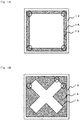
- Fig.1 non-limiting examples regarding the outline of the mesa structure 15 and the type of the n-electrode viewing from the top of the element are shown in Fig.1 , and the "the projection part of the mesa edge" where the current easily concentrates are shown by a circle of broken line.
- the p-electrode 12 and the mesa structure 15 are in contact, but at the cross section shown in Fig.7B , a taper part of the mesa structure or the exposed n-type layer may be present between the edge part of the mesa structure 15 and the n-electrode.
- the p-electrode is formed by taking a predetermined distance from "the projection part of the mesa edge", and the p-electrode restricted area is formed where the p-electrode formation is limited at the area less than the predetermined distance.
- Fig.1A shows the element structure wherein the mesa structure 15 having the rectangular parallelepiped shape is when viewed from the top.
- each corner point of the rectangular parallelepiped shape project out to the area where the n-electrode is formed, and if the p-electrode is formed to this part, the current tends to concentrate to the mesa part right below the p-electrode.
- Fig.1B shows the cross shape mesa structure 15. In this structure, each corner point of the cross projects out to the n-electrode forming area.
- Fig.1C shows the mesa structure 15 having a cross shape of which the edge part is round.
- the edge part of the cross projects out to the n-electrode forming area.
- Fig.1D shows the mesa structure 15 having the comb shape.
- each tip of the comb and the corner point of the rectangular parallelepiped shape project out to the n-electrode forming area.
- Fig.1E is a modified example of Fig.1D , and it shows the structure where the electrode extends in a comb teeth shape from the backbone of the comb.
- Fig.1F shows the structure wherein the n-electrode has a linear part, and further the electrode also extends from the backbone of comb which is forming the n-electrode.
- Fig.1G shows the n-electrode of comb shape surrounding the mesa structure having a comb shape.
- each tip of the comb and the corner point of the rectangular parallelepiped shape which are the p-electrode projects out to the n-electrode forming area.
- the group III nitride semiconductor luminescence element according to the third and fourth inventions for the type of the mesa structure having the constitution shown in the figures or having the similar constitution thereof does not have the p-electrode at the area less than the predetermined distance from the center of the circle showing the "the projection part of the mesa edge".
- the projection part of the mesa edge can be also defined as the mesa part where the n-electrode exists too much in the surrounding, when viewing the group III nitride semiconductor luminescence element from the top. Therefore, in order to determine whether "certain point" of the mesa edge corresponds to "the projection part of the mesa edge", the area of the n-electrode existing around said "certain point" may be considered.
- the certain point as subject to be determined as a center, a circle having a predetermine radius is drawn (hereinafter, this may be referred as “the reference circle"), when the area of the n-electrode present in the circle is large, then this means that the ratio of said "certain point” surrounded by the n-electrode is high.
- the certain point as subject to be determined as a center, a circle having a predetermine radius is drawn, when the area of the mesa part (including the p-electrode) is small, then this means that the ratio of said "certain point” surrounded by the n-electrode is high.
- evaluation parameter n ⁇ electrode area / mesa structure area ⁇ 100 %
- the radius of the reference circle only needs to be about the size so that the circle and other mesa edge does not contact. However, if the circle is too small, the taper part between the mesa edge and the n-electrode, and the area of the exposed n-type layer will be over calculated, thus the circle needs to have a certain size or more. That is, if the reference circle at the mesa edge is too small, the area of the taper part of the mesa part, the area of the exposed n-type layer will be over calculated in the reference circle, thus the total area of the mesa part (including the p-electrode) relatively decreases, and the evaluation cannot be done appropriately.
- the circle having the radius r n which gradually becomes larger is drawn.
- the radius of the circle is small, the relative ratio of the area of the taper part and the area of the n-electrode is large, and as the circle becomes larger, the relative ratio thereof becomes smaller; hence the area of the mesa part (including the p-electrode) and the n-electrode can be evaluated appropriately. Therefore, the radius of the circle wherein the total ratio of the mesa part (including the p-electrode) and the n-electrode in the circle is 80% with respect to the entire area of circle is preferably the radius of the reference circle. Note that, the radius of the reference circle does not have to be large unless the reference circle contacts with other mesa edge.
- the method of determining "the projection part of the mesa edge" using the reference circle will be explained by referring to Fig.2 .
- the mesa part (p-electrode), the n-type layer, and the n-electrode are present in the reference circle, and the taper part of the mesa structure may be observed from the top view.
- the above mentioned evaluation parameter is calculated from the area of the mesa part, the area of the electrode and the entire area of the circle.
- the p-electrode is not shown.
- the p-electrode on the mesa structure 15 has the same shape as the mesa part, or it may be smaller than the mesa part.
- Fig.3 the mesa edge having various outline are schematically shown when viewing the n-electrode from the top. Note that, in the Fig.3 , the area of the exposed n-type layer and the taper part between the electrodes are small, thus it is not shown in the figure. Also, the p-electrode has a same shape as the mesa part but slightly smaller, and the area of the p-electrode is included in the area of the mesa part, thus it is not shown in the figure.
- the area of the mesa part in the reference circle is smaller than the area of the n-electrode. That is, the evaluation parameter is smaller than in case of type "A”, but the area of n-electrode is too large, and a current easily concentrates at this part of the p-electrode.
- the area of the mesa part in the reference circle is smaller than the area of the n-electrode. That is, the area of n-electrode is too large, and a current easily concentrates at this part of the p-electrode.
- the area of the mesa part in the reference circle is smaller than the area of the n-electrode. That is, the area of n-electrode is too large, and a current easily concentrates at this part of the p-electrode.
- the area of the mesa part in the reference circle is about the same as the area of the n-electrode. That is, the evaluation parameter is about 100%.
- the current concentration barely occurs at this part of the p-electrode.
- the area of the mesa part in the reference circle is larger than the area of the n-electrode. That is, the evaluation parameter is less than 100%.
- the current concentration at this part of the p-electrode barely occurs even less than in case of the type "E".
- the area of the mesa structure in the reference circle is larger than the area of the n-electrode. That is, the evaluation parameter is less than 100%.
- the current concentration barely occurs at this part of the p-electrode.
- the p-electrode when the area of the n-electrode is large with respect to the area of the mesa part such as in type "A" to "D", the p-electrode is not provided near said mesa edge, and will have p-electrode restricted area. That is, the area near the mesa edge having large evaluation parameter is the p-electrode restricted area.
- the reference circle is drawn by taking the arbitrary point on the mesa edge as the center point.
- the center of said reference circle is determined as positioned at "the projection part of the mesa edge".
- the p-electrode is provided within the range wherein the distance between the center of the circle and the p-electrode is 1/3 or more of the scattering length L s (12 ⁇ m or more in terms of the absolute distance).
- the area less than 1/3 of the scattering length L s (less than 12 ⁇ m in terms of the absolute distance) from the center of the circle is the p-electrode restricted area.
- Fig.4 the n-type layer and the taper part exposed between the electrodes are small in Fig.4 as well, thus these are not shown in the figure.
- the evaluation parameter is about 300%. Therefore, the p-electrode is not formed within the range less than 1/3 of the scattering length L s (less than 12 ⁇ m in terms of the absolute distance) from the point "X" of the rectangular parallelepiped shape.
- the evaluation parameter is about 100%. Therefore, the limit of forming the p-electrode is on the circle wherein the radius from the point "Y" is 1/3 of scattering length L s (12 ⁇ m in terms of the absolute distance).
- the p-electrode restricted area is the area surrounded by the broken line and the outline of the mesa part as shown in Fig.4B .
- the electrode structure recited in the third invention can be obtained.
- the p-electrode restricted area is formed by taking the distance of 12 ⁇ m or more from the point "X" and point "Y”; thereby the electrode structure recited in the fourth invention can be obtained.
- the p-electrode is preferably not formed for all of the p-electrode restricted area defined in above, but in the present invention the p-electrode may be formed at a part of the p-electrode restricted area, as long as it does not compromise the effect of the present invention. Particularly, at the part spaced away from the mesa edge, the p-electrode may be formed in some cases. Specifically, among the p-electrode restricted area defined in the above, the p-electrode is not formed in 90% or more, more preferably 98% or more and particularly preferably 99% or more of the area.
- the lower limit of the evaluation parameter is 100%, but the lower limit may be set accordingly depending on the material of the laminate semiconductor layer (the mesa structure part) and the driving environment of the element or so.
- the lower limit of the acceptable evaluation parameter is set low from the point to ensure the suppression of the current concentration to the mesa part, thereby the p-electrode restricted area is made wider.
- the evaluation parameter may be 80% or more, and it may be 60% or more.
- the evaluation parameter may be 120% or more, and it may be 140% or more.
- the radius of the reference circle may be 12 ⁇ m. Also, as the electrode becomes narrower, the radius of the reference may become smaller; thereby the appropriate evaluation can be carried out. Note that, in this case, the circle should not contact with other mesa edge.
- the p-electrode restricted area is provided within the predetermined range from "the projection part of the mesa edge".
- the p-electrode is formed to the mesa part other than the p-electrode restricted area (hereinafter it may be referred as "the p-electrode allowed area"), but the p-electrode does not necessarily have to be formed at the entire p-electrode allowed area.
- the p-electrode only needs to be formed so that it is conducted to at least part of the p-electrode allowed area.
- the outer shape of the p-electrode formed near the projection part of the mesa edge is preferably formed in an arc shape as shown in Fig.5 , an oval arc shape and a parabolic shape or so.
- a space may be provided in a width less than 1/3 of the scattering length L s or less than 12 ⁇ m between the edge part of the p-electrode and the mesa edge.
- Fig.5 shows an example provided with the space having the width of 5 ⁇ m.
- p-electrode is not provided within the predetermined range from "the projection part of the mesa edge" wherein the evaluation parameter becomes certain value or more, but the evaluation parameter showing the degree of the projection of the mesa part as discussed in above continuously changes due to the shape of the mesa edge. Therefore, depending on the degree of the projection of the mesa part, the distance from the mesa edge to the p-electrode may be provided.
- the evaluation parameter at the point "X" is high (the mesa part is highly projected out), thus the p-electrode is prohibited from forming near this area (for example within 12 ⁇ m).
- the evaluation parameter of the point "Y” is low, and the current concentration barely occurs, thus the distance between the point "Y” and the p-electrode may be less than 1/3 of the scattering length L s or less than 12 ⁇ m.
- the evaluation parameter is determined, and based on the result thereof, "the degree of the projection" is evaluated, thereby the p-electrode restricted area from said mesa edge may be set.
- the p-electrode restricted area is larger; and at the mesa edge having low evaluation parameter, the p-electrode regulated area may be smaller than the above mentioned. Therefore, it may be effective to define the p-electrode regulated area using the absolute value or squared value of the evaluated parameter.
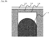
- the mesa edge is the edge part of the rectangular parallelepiped shape as shown in Fig.6A
- the distance from the corner point of the rectangular parallelepiped shape to the p-electrode is long in the longitudinal direction, thus the p-electrode is provided so that the distance from the middle point in the short direction of the rectangular parallelepiped shape to the p-electrode is short.
- the distance with the p-electrode continuously changes such that it is long from the corner point in the longitudinal direction and short from the middle point; and as approaching the middle point, the change in the distance becomes moderate.
- the mesa edge and the p-electrode edge part may match at the end.
- the mesa edge is an arc or oval arc shape as shown in Fig.6B
- the distance from the top of the arc (oval arc) in the short direction is long.
- the p-electrode is provided so that the distance between the mesa edge and the p-electrode becomes shorter.
- the distance with the p-electrode is long from the top of the arc mesa edge, and short from the both end of the arc; thus the distance continuously changes, and as approaching to the both ends, the change in the distance becomes moderate.
- the mesa edge and the p-electrode edge part may match at the end.
- the maximum value and the minimum value of the luminescence intensity has a ratio (hereinafter, it may be referred as the luminescence intensity ratio) of preferably 2.1 or less.
- the luminescence intensity ratio a ratio of preferably 2.1 or less.
- the luminescence intensity distribution can be obtained by measuring the luminescence intensity distribution of the luminescence element which is described in below; and the maximum value and minimum value of the luminescence intensity is the maximum value and minimum value of the luminescence intensity at the luminescence area of the luminescence plane.
- the luminescence area of the luminescence plane is the area emitting the light among the opposite plane of the laminate plane of the substrate 11.
- the lower face of the translucent substrate 11 is ground or polished, thereby the translucent substrate 11 is made thin and the transmission factor can be improved.
- the luminescence element is produced using the known separation method of the luminescence element such as scribing, dicing and laser welding or so.
- the luminescence element of the present invention may be combined with the conventional technology such as forming the high resistance layer, and forming the trench or so.
- the device for measuring the luminescence intensity distribution comprises an electric control circuit applying the voltage to the luminescence element, an optical system regulating the measuring range by lens and camera, a photodetection part, and a data analysis device.
- the area of 10 ⁇ m x 10 ⁇ m is defined as 1 range, and the luminescence intensity in the luminescence area of the luminescence plane is measured and mapped, thereby the distribution of the luminescence intensity is measured.
- the place where the current concentration takes place is observed with strong luminescence intensity; hence the effect of current concentration suppression due to the regulation of the distance between the mesa edge and the p-electrode can be confirmed by this measurement.
- the laminate semiconductor layer having the cross section structure shown in Fig.7B was formed.
- Al 0.7 Ga 0.3 N layer (1 ⁇ m) doped with 1.0 x 10 19 [cm -3 ] of Si was formed as the n-type semiconductor layer on the C-plane AIN substrate (square having 7 mm on one side, thickness of 500 ⁇ m).
- the active layer having the quantum well structure (quantum well layer of 2 nm, and barrier layer of 7 nm) was formed on this n-type layer.
- the compositions of the quantum well layer and the barrier layer were Al 0.5 Ga 0.5 N and Al 0.7 Ga 0.3 N respectively, and 1.0 x 10 18 [cm -3 ] of Si was doped to the barrier layer.
- the active layer constitutes from the laminate structure comprising three layers of the quantum well layers and four layers of the barrier layers.
- AIN layer (15 nm) doped with 5 x 10 19 [cm -3 ] of Mg was formed as the electron block layer.
- Al 0.8 Ga 0.2 N layer 50 nm doped with 5 x 10 19 [cm -3 ] of Mg was formed as the p-clad layer.
- GaN layer 100 nm doped with 2 x 10 19 [cm -3 ] of Mg was formed as the p-contact layer.
- the obtained semiconductor wafer was heat treated in N 2 atmosphere or 20 minutes at 900°C. Then, after forming a predetermined metal mask pattern on the surface of the p-contact layer by a photolithography and a vacuum evaporation, the dry etching was carried out to the p-contact layer surface not formed with the pattern until the n-type layer was exposed, thereby a cross shape mesa structure having a round end part as shown in Fig.1C was formed.
- the amount ground by the etching of the n-type layer was 300 nm.
- a resist pattern was formed on the p-contact layer by photolithography, then Ti (20 nm)/ Al (200 nm)/ Au (5 nm) layer was formed by vacuum evaporation, and a heat treatment was carried out for 1 minute at 810°C in N 2 atmosphere thereby the n-electrode was formed.
- Ni (20 nm)/ Au (50 nm) layer was formed on the p-type layer so that the predetermined range from the edge part was the p-electrode restricted area, then the p-electrode was formed by firing for 3 minutes at 550°C in O 2 atmosphere.
- the obtained semiconductor wafer was cut out in a square having 750 ⁇ m on one side; thereby the nitride semiconductor luminescence element was made (the nitride semiconductor luminescence element having the luminescence peak wavelength of 265 nm).
- the instantaneous deterioration rate (the ratio of the element having significant drop of the output among all of the elements (the ratio of the element deteriorated due to the current concentration at the p-electrode)) after 500 hours was 2%.
- Example 2 showed 4%
- Comparative example 1 showed 20%
- Comparative example 2 showed 24%.
- the distance between the mesa edge and the p-electrode is 20 ⁇ m or more in the p-electrode restricted area, then significant improvement of the instantaneous deterioration rate was observed.
- the scattering length L s of the obtained luminescence element was calculated, it was 60 ⁇ m; hence 20 ⁇ m is 1/3 of the scattering length L s .
- the nitride semiconductor luminescence element was produced as same as Example 1, except for changing the amount of ground of the n-type layer by dry etching to 100 nm when forming the n-electrode.
- the instantaneous deterioration rate (the ratio of the element having significant drop of the output among all of the elements (the ratio of the element deteriorated due to the current concentration at the p-electrode)) after 500 hours was 2%.
- Example 4 showed 4%, Comparative example 3 showed 16% and Comparative example 4 showed 24%.
- the distance between the mesa edge and the p-electrode is 12 ⁇ m or more in the p-electrode restricted area, then significant improvement of the instantaneous deterioration rate was observed.
- the scattering length L s of the obtained luminescence element was calculated, it was 36 ⁇ m; hence 12 ⁇ m is 1/3 of the scattering length L s .
- the results of measuring the ratio between the maximum value and the minimum value of the luminescence intensity (the luminescence intensity ratio) in the luminescence area of the luminescence plane are shown in Table 1.
- the luminescence intensity ratio was 2.10 (Example 4), when the distance between the p-electrode and the mesa edge is 12 ⁇ m which corresponds to 1/3 of the scattering length L s .
- Example 3 Example 4 Comparative example 3 Comparative example 4 Distance between p-electrode and mesa edge at projection part [ ⁇ m] 20 12 8 5 Instantaneous deterioration rate [%] 2 4 16 24 Luminescence intensity ratio 2.02 2.10 2.28 2.50
- the distance between a part of an edge of said mesa structure and an outer peripheral of said p-electrode is predetermined value or more, thereby the current running between the p-electrode and the n-electrode is suppressed from concentrating near the mesa edge without excessively increasing the driving voltage.
- the group III nitride semiconductor luminescence element can be obtained which barely having a local deterioration at the mesa structure, and also barely having uneven luminescence because the current uniformly runs in the active layer.
Landscapes
- Led Devices (AREA)
Abstract
Description
- The present invention relates to a group III nitride semiconductor luminescence element comprising a luminescence peak wavelength of ultraviolet ray. Particularly, the present invention relates to a technology of preventing the deterioration of the element caused by the current concentration to an edge part of a mesa structure of the luminescence element. Also, the present invention relates to a wafer comprising the constitution of said luminescence element.
-
Fig.7A and Fig.7B show typical schematic structures of a group III nitridesemiconductor luminescence element 20.Fig.7A is a top view of the element, andFig.7B shows the cross section at A-A line ofFig.7A . The group III nitridesemiconductor luminescence element 20 is formed with a laminate (hereinafter, this may be referred as a "laminate semiconductor layer") comprising on one surface side of a substrate 11, a n-type layer 12, an active layer 13, and a p-type layer 14; and having amesa structure 15 at a part of the laminate semiconductor layer thereof is known. Themesa structure 15 is formed by forming the laminate semiconductor layer comprising on one surface side of the substrate 11, the n-type layer 12, the active layer 13, and the p-type layer, and then removing a part of the laminate structure by etching or so to expose a part of the n-type layer 12. A part having a plateau shape (also called as a mesa) including the active layer 13 and the p-type layer is maintained; thereby themesa structure 15 is formed (see the patent document 1). An n-type electrode 16 is formed on the exposed surface of the n-type layer 12, and a p-type electrode 17 is formed at the surface of the p-type layer 14. - For the group III nitride
semiconductor luminescence element 20 comprising themesa structure 15, when the driving voltage is applied to the p-type electrode 17 on the p-type layer and the n-electrode 16 on the n-type layer, the current runs the pathway having a low resistance (usually the shortest pathway) between the p-type electrode and the n-type electrode, thus the current runs by concentrating at near the edge part of the mesa structure 15 (hereinafter, it will be called as a "mesa edge") close to the n-type electrode and the p-type electrode. As a result, the current does not flow uniformly to the active layer 13, thus uneven luminescence occurs. Also, since the current concentrates at the mesa edge, a local heat generation occurs near the mesa edge. As a result, the deterioration of the luminescence element easily proceeds, and causes the decrease in the luminescence efficiency, increase in the driving voltage, and decrease in the reliability. - The
patent document 2 discloses the ultraviolet semiconductor luminescence element wherein the high resistance layer having higher resistance than the p-type layer or p-electrode is formed in a shape along the shape of p-type layer side at closer side to the n-type electrode on the surface of the p-type layer. As disclosed in thepatent document 2, when the high resistance layer is formed on the p-type layer close to the mesa edge, the current can be suppressed from concentrating near the mesa edge. However, due to the presence of the high resistance layer, the resistance between the p-type electrode and the semiconductor layer becomes larger, and the driving voltage becomes larger as well. - The
patent document 3 discloses the semiconductor luminescence element wherein a trench is formed between the p-electrode and the n-electrode. By forming the trench, the length of the current pathway running between the p-electrode and the n-electrode is suppressed from varying; thereby the current is suppressed from concentrating to a particular part. However, in order to make the varying of the length of the current pathway sufficiently small, the depth of the trench must be deep. If the trench is made deep, the current pathway as a whole becomes longer, and the resistance becomes large, and the driving voltage also becomes large. - Further, due to various designs of the recent devices, the luminescence element having various shapes and constitution has been proposed, and also there are variety of mesa structures and designs of the electrode shapes. The art of forming the high resistance layer and the trench as mentioned in the above will increase the steps for producing the luminescence element, hence it has become difficult to correspond to the various mesa structure and electrodes shape in a timely manner.
- Further particularly, the deep ultraviolet ray luminescence element having the luminescence peak wavelength of 200 to 350 nm is difficult to produce; hence the yield tends to easily decrease. Further, when the current is running, the current tends to concentrate near the mesa edge, thus such part may deteriorate due to the heat or so and the quality tends to be damaged. Thus, the development of the luminescence element capable of suppressing the deterioration caused by the current concentration near the mesa edge was in demand.
-
- Patent document 1:
JP Patent Application Laid Open No.2014-96539 - Patent document 2:
JP Patent Application Laid Open No.2014-96460 - Patent document 3:
JP Patent Application Laid Open No.2007-134700 - The object of the present invention is to provide the group III nitride semiconductor luminescence element capable to suppress the deterioration of the luminescence element caused by the current flowing between the p-electrode and the n-electrode concentrating near the mesa edge, without increasing the steps for producing the luminescence element, and without excessively increasing the driving voltage.
- The present inventors have speculated that the above object can be attained by regulating the structure of the p-electrode, and has carried out keen examination. Further, the present inventors have found that the above object can be attained by forming the p-electrode by taking certain distance from the edge part of the mesa structure, particularly at the part where the mesa structure is projecting out; thereby the present invention was attained.
- That is, the first invention is a group III nitride semiconductor luminescence element having a mesa structure comprising a n-type layer, a p-type layer, an active layer provided between the n-type layer and the p-type layer, a n-electrode provided on said n-type layer, and a p-electrode provided on said p-type layer; wherein
- from a top view of said group III nitride semiconductor luminescence element, a distance between a part of an edge of the mesa structure and an outer peripheral of said p-electrode is 1/3 or more of a scattering length Ls, or
- from a top view of said group III nitride semiconductor luminescence element, a distance between a part of the edge of the mesa structure and the outer peripheral of said p-electrode is 12 µm or more. As the production technology of the present luminescence element, the object of the present invention can be sufficiently attained, when the distance between the part of the mesa edge and the outer peripheral of the p-electrode is 12 µm or more.
- The second invention is the group III nitride semiconductor luminescence element as set forth in the first invention, wherein the distance between a projection part of the edge of the mesa structure and the outer peripheral of said p-electrode is 1/3 or more of the scattering length Ls. The current tends to easily concentrate to the p-electrode part at the projection part of the mesa edge, thus the distance between the projection part of the mesa edge and said peripheral of the p-electrode is preferably within the above mentioned range.
- The third invention is the group III nitride semiconductor luminescence element as set forth in the first invention, wherein the distance between a projection part of the edge of the mesa structure and the outer peripheral of said p-electrode is 12 µm or more.
- The fourth invention is the group III nitride semiconductor luminescence element as set forth in first to third inventions, wherein the luminescence peak wavelength is 200 to 350 nm. The group III nitride semiconductor luminescence element having the luminescence peak wavelength of 200 to 350 nm is difficult to produce, and the improvement of the yield is strongly demanded, thus the present invention is suitable.
- Further, the fifth invention is a wafer including the constitution of a group III nitride semiconductor luminescence element comprising a n-type layer, a p-type layer, an active layer provided between the n-type layer and the p-type layer, a n-electrode provided on said n-type layer, and a p-electrode provided on said p-type layer, wherein
the constitution of said group III nitride semiconductor luminescence element is as set forth in saidinventions 1 to 4. - In the present invention, when the group III nitride semiconductor luminescence element is viewed from the top, the distance between a part of the mesa edge and the outer peripheral of said p-electrode is set to predetermine value or more, thereby a p-electrode restricted area is provided near the edge part of the mesa structure. In this p-electrode restricted area, the ratio of the p-electrode formed is regulated to be low compared to the mesa part other than this area. By providing the p-electrode restricted area, the current running between the p-electrode and the n-electrode is suppressed from concentrating near the mesa edge without excessively increasing the driving voltage of the element. As a result, the group III nitride semiconductor luminescence element barely having the local deterioration in the mesa structure, and also barely having the uneven luminescence can be obtained because the current evenly runs in the active layer.
- As a result, the quality damage caused by the current concentration near the mesa edge when running the current can be decreased, thus the yield of the luminescence element can be improved.
- Particularly, the ultraviolet ray emitting element having the luminescence peak wavelength of 200 to 350 nm tends to have decreased yield because it is difficult to produce due to the influence of the composition of each layer, compared to the luminescence element having the luminescence peak wavelength longer than 350 nm, such as for example the luminescence element having the visible light range. The present invention can suppress the decrease of the yield which is caused by the local deterioration of the mesa structure; hence it is suited as the ultraviolet ray emitting element having the luminescence peak wavelength of 200 to 350 nm.
-
- Fig.1A
- shows an example of the group III nitride semiconductor luminescence element viewing from the top.
- Fig.1B
- shows an example of the group III nitride semiconductor luminescence element viewing from the top.
- Fig.1C
- shows an example of the group III nitride semiconductor luminescence element viewing from the top.
- Fig.1D
- shows an example of the group III nitride semiconductor luminescence element viewing from the top.
- Fig.1E
- shows an example of the group III nitride semiconductor luminescence element viewing from the top.
- Fig.1F
- shows an example of the group III nitride semiconductor luminescence element viewing from the top.
- Fig.1G
- shows an example of the group III nitride semiconductor luminescence element viewing from the top.
- Fig.2
- shows the method of determining "the projection part of the mesa edge" using a reference-circle.
- Fig.3
- shows various shape of the mesa edge.
- Fig.4A
- shows the method of determining the p-electrode restricted area.
- Fig.4B
- shows the method of determining the p-electrode restricted area.
- Fig.5
- shows the relationship of the position of the mesa edge and the p-electrode of the element in the example.
- Fig.6A
- shows the example of the relationship of the position between the mesa edge and the p-electrode.
- Fig.6B
- shows the example of the relationship of the position between the mesa edge and the p-electrode.
- Fig.7A
- shows the example of the typical group III nitride semiconductor luminescence element viewing from the top.
- Fig.7B
- shows the cross section of the typical group III nitride semiconductor luminescence element.
- Hereinafter, the embodiment of the present invention will be explained by referring to the figures. Note that, the luminescence element described in below is one example realizing the concept of the present invention, and the present invention is not limited thereto. For example, the size, material, shape and relative position or so of the element described in below is merely an example used for describing and the present invention is not to be limited thereto, unless mentioned otherwise. Note that, the size and the relationship of the position of the members shown in each figure may be exaggerated in order to make the description clear.
- The luminescence range of the light emitted from the group III nitride semiconductor luminescence element of the present invention is not particularly limited. According to the present invention, regardless of the luminescence range, the decrease of the output caused by the deterioration due to the local current concentration in the mesa structure is suppressed, and the yield can be improved. Preferably, the present invention is used for the group III nitride semiconductor luminescence element comprising the luminescence peak wavelength in the visible light range or in the ultraviolet range. More preferably, the present invention is used for the group III nitride semiconductor luminescence element emitting the ultraviolet ray having the luminescence peak wavelength of 200 to 350 nm. Hereinafter, the group III nitride semiconductor luminescence element having the luminescence peak wavelength of 200 to 350 nm will be mainly discussed.
- As shown in
Fig.7A and Fig.7B , the typical group III nitridesemiconductor luminescence element 20 comprises a n-electrode 16, and a p-electrode 17, a substrate 11, and a mesa structure 15 (a laminate semiconductor layer) including a n-type layer 12, an active layer 13 and p-type layer 14. Herein below, a non-limiting typical example thereof will be discussed. - Note that, a refraction factor, a transmission factor, and a reflection factor are based on the light having the wavelength of 265 nm. This is because DNA has a maximum absorbance near the wavelength of 265 nm, thus the light having the wavelength of 265 nm is most suited for sterilization, and hence will have high industrial applicability. Hereinafter, when simply referring to the refraction factor, the transmission factor, and the reflection factor, these are values with respect to the light having the wavelength of 265 nm.
- The substrate 11 allows the epitaxial growth of the group III nitride semiconductor luminescence element on the surface, and as long as it is a substrate allowing the ultraviolet ray to transmit through, it is not particularly limited. As the material used for the substrate 11, for example, sapphire, SiC (silicon carbide), AIN (aluminum nitride), Si (silicon) or so may be mentioned. Among these, an AIN single crystal substrate using c-plane as a principle plane is preferable.
- The higher the transmission factor of the substrate 11 with respect to the light having the wavelength of 265 nm is, the better it is; and preferably it is 50% or more, and more preferably 60% or more. The upper limit of the transmission factor of the substrate 11 is preferably 100%; and from the point of the industrial production, it is 80%. The transmission factor of the translucent substrate can be regulated by the material, the thickness of the substrate, the crystallinity, and the impurity content.
- The thickness of the substrate 11 is not particularly limited, but preferably it is 30 to 150 µm, and more preferably 50 to 100 µm. By setting the thickness of the substrate 11 within the above mentioned range, the transmission factor is improved, and the productivity is improved. The thickness of the substrate 11 only needs to satisfy the above mentioned range after the group III nitride semiconductor luminescence element is produced; and the lower face of the substrate may be ground or polished after laminating the laminate semiconductor layer or the electrode on the substrate, thereby the thickness of the substrate may be within the above mentioned range.
- The laminate semiconductor layer (the main part of the element including the
mesa structure 15 ofFig.7 ) is formed on the substrate 11 as shown inFig.7B , and the n-type layer 12, the active layer 13 and the p-type layer 14 (the layer formed of a p-type clad layer and a p-type contact layer) are stacked in this order. - The n-
type layer 12 is a group III nitride semiconductor constituted by AlxInyGazN (x, y, and z are rational number satisfying 0 < x ≤ 1.0, 0 ≤ y ≤ 0.1, 0 ≤ z <1.0, and x + y + z = 1.0), and preferably it includes impurity. - The impurity is not particularly limited, but preferably Si, Ge, Sn or so may be mentioned. Among these, Si and Ge are preferable. The concentration of the impurity is 1.0 x 1017 cm-3 or more and 5.0 x 1020 cm-3 or less; and preferably 1.0 x 1018 cm-3 or more and 5.0 x 1019 cm-3 or less. By setting the concentration of the impurity within the above range, the crystallinity and the contact characteristic of the n-type layer improves. Such n-type layer may be produced by MOCVD method.
- The refraction factor of the n-type layer is not particularly limited, but it is 1.5 to 3.0. The refraction factor may be regulated by the composition of the n-type layer.
- The thickness of the n-type layer is 100 nm or more and 10000 nm or less, and preferably 500 nm or more and 3000 nm or less. By having the thickness of the n-type layer within the above range, the crystallinity and the conductivity of the n-type layer improves.
- Note that, although it is not shown in
Fig.7 , the group III nitridesemiconductor luminescence element 20 may comprise a buffer layer including the group III nitride semiconductor having the composition same or similar to AIN or the above mentioned n-type layer, in between the substrate 11 and the n-type layer 12. - The active layer 13 is formed of the laminate structure comprising a quantum well layer constituted of AlxInyGazN (x, y, and z are rational number satisfying 0 < x ≤ 1.0, 0 ≤ y ≤ 0.1, 0 ≤ z < 1.0, and x + y + z = 1.0), and a barrier layer constituted of AlxInyGazN (x, y, and z are rational number satisfying 0 < x ≤ 1.0, 0 ≤ y ≤ 0.1, 0 ≤ z < 1.0, and x + y + z = 1.0) having larger band gap energy than said quantum well layer. The active layer may be a multiple quantum well layer structure, or it may be a single quantum well structure.
- The thickness of the quantum well layer is 1 nm or more, preferably 2 nm or more, and the upper limit is 100 nm. The thickness of the barrier layer is 1 nm or more, preferably 2 nm or more, and the upper limit is 1 µm. Such active layer can be produced by MOCVD method.
- The p-type layer is constituted from the p-type clad layer and the p-type contact layer. The p-type clad layer is a group III nitride semiconductor constituted by AlxInyGazN (x, y, and z are rational number satisfying 0 < x ≤ 1.0, 0 ≤ y ≤ 0.1, 0 ≤ z < 1.0, and x + y + z = 1.0), and preferably it includes impurity.
- The impurity of the p-type clad layer is preferably Mg. The concentration of impurity in the p-type clad layer is 1.0 x 1017 cm-3 or more and 5.0 x 1020 cm-3 or less; and preferably 1.0 x 1018 cm-3 or more and 5.0 x 1020 cm-3 or less. The thickness of the p-type clad layer is 5 nm or more and 100 nm or less, and preferably 10 nm or more and 50 nm or less.
- The p-type contact layer is a group III nitride semiconductor constituted by AlxInyGazN (x, y, and z are rational number satisfying 0 < x ≤ 1.0, 0 ≤ y ≤ 0.1, 0 < z ≤ 1.0, and x + y + z = 1.0). Preferably, the p-type contact layer is constituted of GaN. By constituting the p-type contact layer by GaN, that is p-GaN layer, then the contact characteristic of the p-type contact layer can be improved. Also, the p-type contact layer preferably includes the impurity.
- The impurity of the p-type contact layer is preferably Mg as similar to the p-type clad layer. The concentration of impurity in the p-type contact layer is 1.0 x 1017 cm-3 or more and 5.0 x 1020 cm-3 or less; and preferably 1.0 x 1018 cm-3 or more and 5.0 x 1020 cm-3 or less. The thickness of the p-type contact layer is 1 nm or more and 100 nm or less, and preferably 5 nm or more and 50 nm or less. By having the thickness of the p-type contact layer within the above mentioned range, the ultraviolet ray transmission characteristic and the contact characteristic of the p-type layer improves.
- The transmission factor of the p-type layer, which is the transmission factor with respect to the light having the wavelength of 265 nm is preferably 50% or more, and more preferably 60% or more. The upper limit of the transmission factor is not particularly limited, but from the point of the production stability, it is 85%. By setting the transmission factor of the p-type layer with respect to the light having the wavelength of 265 nm within the above mentioned range, the light-extraction efficiency improves.
- The transmission factor of the p-
type layer 14 largely depends on the thickness and the composition of the p-type contact layer. When constituting the p-type contact layer with GaN (p-GaN layer), GaN has an absorption edge at the wavelength of 365 nm, thus if it is too thick, the light having the wavelength of 265 nm will barely transmit through. The relation between the thickness of the p-type contact layer and the transmission factor can be expressed by T = exp(-αt), wherein "T" is the transmission factor, "α" is the absorbance coefficient (cm-1), and "t" is thickness (cm). The absorbance coefficient α of GaN at the wavelength of 265 nm is 1.8 x 10⁵ (cm-1). That is, the thinner the p-GaN layer is, the higher the transmission factor can be. However, if the p-GaN layer is too thin, the current does not sufficiently spread, thus the electric characteristic of the luminescence element may be poor. - However, when constituting the p-type contact layer with GaN (p-GaN layer), the thickness of the p-GaN layer is preferably 1 nm or more and 40 nm or less, preferably 10 nm or more and 30 nm or less. By having the thickness of the p-GaN layer within the above mentioned range, the current will sufficiently spread in the p-type contact layer, and the electric characteristic of the luminescence element improves, and also the ultraviolet ray transmission characteristic of the p-type layer improves. Such p-type layer can be produced by MOCVD method.
- The n-
electrode 16 is formed on the exposed face of the n-type layer 12. The exposed face of the n-type layer is formed by the means of etching or so. Due to the forming of the exposed face of the n-type layer, the laminate semiconductor layer remains in a plateau shape; thereby themesa structure 15 is formed. The n-electrode on the n-type layer is formed at the lower part along the lower mesa edge of the mesa structure, however it may be a structure wherein a space is slightly taken from the lower mesa edge of the mesa structure, and the n-type layer 12 is exposed between themesa structure 15 and the n-electrode 16. - From the top view of the group III nitride
semiconductor luminescence element 20, the n-electrode 16 may be formed so as to surround the entire p-electrode 17 along the mesa edge, or the n-electrode may surround part of the p-electrode. Alternatively, the p-electrode may be formed so as to surround the n-electrode. - As the method of etching, for example a dry etching such as reactive ion etching, and inductive coupling plasma etching or so may be mentioned. After forming the exposed face of the n-
type layer 12, in order to remove the damage by the etching, preferably the exposed face is subjected to a surface treatment by acid or alkali. Then, the n-electrode 16 comprising an ohmic characteristic is formed to the exposed face of the n-type layer. - The n-electrode can be formed by a lift-off method. As the lift-off method, a photoresist is coated to the face where the electrode is to be formed, and the ultraviolet ray is irradiated using the UV exposure machine having a photomask. Then, it is immersed in the developing solution to dissolve the photoresist exposed to the light thereby the desired pattern is formed. Then, an electrode metal is deposited on the photoresist, and the photo-resist is dissolved by a stripping solution thereby the electrode metal is formed. Also, as other method of forming, the electrode metal film is formed on the electrode forming face, and the photoresist is coated, then the photoresist is formed via the steps of light exposing and developing. Then, the dry etching or wet etching is carried out using the photo-resist as a mask to form the electrode metal, and dissolving the photo-resist by stripping solution. The lift-off method is preferable since the steps are relatively simple.
- As the method for depositing the n-electrode metal, for example, a chemical vapor phase method such as the vacuum evaporation and spattering or so may be mentioned. Particularly, the vacuum evaporation method is preferable as the impurity included in the electrode metal can be removed. The material used for the n-electrode can be selected from the known materials. For example, Ti, Al, Rh, Cr, In, Ni, Pt and Au or so may be mentioned. Among these, Ti, Al, Rh, Cr, Ni and Au are preferable. Particularly, the combination of Ti, Al and Au are preferable since the ohmic characteristic and the reflection factor can be improved. The n-electrode may be single layer or multiple layer structure comprising alloy or oxides of these metals.
- The thickness of the n-electrode is not particularly limited, but considering the stability of the production, it is preferably 2 nm or more and the upper limit is 2 µm.
- As shown in
Fig.1 , the type of the n-electrode is not particularly limited, and it may be formed so as to surround theentire mesa structure 15 along the mesa edge (Fig.1A to Fig.1F ), or it may be formed so that the n-electrode surrounds part of the mesa structure 15 (Fig.1G ). In this case, the n-electrode may be formed so as to surround the p-electrode (Fig.1A to Fig.1E andFig.1G ), or it may be other way around and the p-electrode may be formed so as to surround the n-electrode (Fig.1F ). - As shown in
Fig.1F , in case the n-electrode comprises the linear part, the width of the n-electrode is not particularly limited, but usually it is 5 to 100 µm or so, and preferably 10 to 50 µm. In this case, the width of the n-electrode may not be uniform. For example, the part having a wide width and narrow width may coexist. In this case, the average width of the n-electrode may be within the above mentioned range of width. - In order to improve the contact characteristic with the n-type layer, preferably after depositing the n-electrode metal, a heat treatment is carried out at 300°C to 1100°C for 30 seconds to 3 minutes. The temperature and time of the heat treatment can be selected from the most suitable condition depending on the metal type and the thickness of the n-electrode.
- The p-
electrode 17 is formed on the p-type layer 14 of themesa structure 15. The type of the p-electrode 17, that is the shape and the size of the p-electrode 17 are about the same as themesa structure 15. In the present invention, the position of the p-electrode 17 formed is set based on the predetermined rule related to the shape of themesa structure 15. Thereby, the current which tends to easily concentrate near the mesa edge is dispersed, and the current is suppressed from concentrating to the mesa edge. The rule of forming the p-electrode will be discussed in following, but first a non-limiting typical example regarding the property of the general p-electrode and the method of forming thereof will be explained. - The p-
electrode 17 may comprise an ultraviolet ray transmission property. The transmission factor of the p-electrode with respect to the light having the wavelength of 265 nm is preferably 60% or more, and more preferably 70% or more. The upper limit of the transmission factor is not particularly limited, and preferably it is 100%, but industrially it is 90%. Note that, the transmission factor of the wavelength with respect to the light having the wavelength of 265 nm is 60% or more, then sufficient transmission property can be obtained within the range of the wavelength of 200 to 350 nm. - The p-electrode is preferably formed by the lift-off method as similar to the n-electrode. The metal material used for the p-electrode can be selected from the known materials. For example, Ni, Cr, Au, Mg, Zn, Pd and Pt or so may be mentioned. Among these, the combination of Ni and Au is preferable. The p-electrode may be single layer or multiple layer structure comprising alloy or oxides of these metals.
- The shape of the p-electrode is not particularly limited, but as already mentioned, it is formed to have about the same shape but slightly smaller than the
mesa structure 15. Therefore, the shape of the p-electrode may be a rectangular parallelepiped shape which is almost the same shape as themesa structure 15 as shown inFig.1A , or it may be a cross shape as shown inFig.1B and1C , or it may be a comb shape as shown inFig.1D to 1G . The width of the p-electrode is not particularly limited, but in case of the shape similar to themesa structure 15 as shown inFig.1B to Fig.1G , then usually the width is 5 to 100 µm or so, and preferably 10 to 50 µm or so. The width of the p-electrode may not be uniform. For example, the part having a wide width and narrow width may coexist. In this case, the average width of the p-electrode may be within the above mentioned range. - As the method of depositing the p-electrode metal, as similar to the method of forming the n-electrode, for example the vacuum evaporation, spattering and chemical vapor phase method or so may be mentioned. Particularly, the vacuum evaporation is preferable as the impurity in the electrode metal can be removed. In order to improve the contact characteristic with the p-type layer, preferably after depositing the p-electrode metal, a heat treatment is carried out at 200°C to 800°C for 30 seconds to 3 minutes. The temperature and time of the heat treatment can be selected from the most suitable condition depending on the metal type and the thickness of the p-electrode.
- As shown in
Fig.7 , the p-electrode 17 is formed almost the same as themesa structure 15, on the p-electrode layer 14 positioned at the upper part of themesa structure 15 having a plateau shape. The n-electrode 16 is formed at the lower part viewing from the mesa structure. Regarding the conductivity between the n-electrode 16 and the p-electrode 17, the pathway with lower resistance will have a priority, thus the current tends to concentrate to area near the edge part of themesa structure 15 having the shortest distance between the n-electrode and the p-electrode. - Thus, in the present invention, in order to avoid the current concentration at the mesa edge, a certain distance is provided between the mesa edge and the p-electrode. That is, in the first invention, when viewing the group III nitride semiconductor luminescence element from the top, the distance between a part of the mesa edge and an outer peripheral of said p-electrode is 1/3 or more of a scattering length Ls. That is, between the p-electrode and a part of the mesa edge, the p-electrode restricted area exists where the electrode is restricted from forming. In other words, the present invention comprises the p-electrode restricted area of which the width is 1/3 or more of a scattering length Ls, at a part near the edge part of the mesa structure.
- Here, "mesa edge" refers to the outline of the
mesa structure 15, and to the edge part of the mesa structure from the top view, further it is shown as the outer peripheral (outline) of the p-type layer 14. The mesa structure is formed by etching the laminate semiconductor layer almost perpendicularly, but it does not necessarily have to be completely perpendicular; and it may be formed in a taper shape from the top to the bottom of the mesa structure. In case the area of the top part of the mesa structure is smaller than the area of the bottom part of the mesa structure, the taper part is observed from the top view. When the area of the top part of the mesa structure is larger than the area of the bottom part of the mesa structure, then the taper part is formed in an overhang form thus it is difficult to observe from the top view. - In the below discussion, the mesa edge is the edge part of the mesa structure from the top view, also defined as the outer peripheral (outline) of the p-
type layer 17 positioned at the upper most layer of the mesa structure, and it does not include the taper part. - Also, the distance between the mesa edge and the outer peripheral of the p-electrode refers to the shortest pathway to the outline of the p-electrode from the arbitrarily selected mesa edge, when viewing from the top.
- "A part" of the mesa edge means that not all of the mesa edge necessarily needs to have a distance of 1/3 or more of a scattering length Ls from the p-electrode, and in some part, the mesa edge and the outline of the p-electrode may be closely positioned in a distance of 1/3 or less. That is, as long as the mesa edge and the p-electrode is spaced a part by a predetermined distance at the part where the current concentration easily occurs, then the current concentration which causes the element malfunction can be solved. On the other hand, at the part where the current concentration barely occurs, the mesa edge and the outline of the p-electrode may be close to each other, and from the top view, the p-electrode and the n-electrode may be close to each other in a distance less than 1/3 of a scattering length Ls.
- The mesa edge where the current concentration tends to occur is surrounded by the n-electrode. Such mesa edge has various shape depending on the outline shape of the mesa structure, however it exist usually in the ratio of 5 to 30% with respect to the entire peripheral of the mesa structure. However, among the mesa edges, for the mesa edges surrounded by the n-electrode, in the present invention, certain distance or more is taken between the mesa edge and the p-electrode; thereby the p-electrode restricted area is provided.
- As such, by taking a distance between the mesa edge and the p-electrode, the current will not run to this part, thus the current concentration at the area near the edge part of the
mesa structure 15 can be suppressed. If the distance between the outer peripheral of the p-electrode is 1/3 or more of a scattering length Ls for all mesa edges, then the driving voltage of the group III nitride semiconductor luminescence element rises, and the luminescence efficiency may decline. Therefore, in the present invention, particularly at the part where the current tends to concentrate, the distance between mesa edge and the p-electrode may be predetermined value or more. - According to the examination by the present inventors, if the distance between a part of the mesa edge and the outer peripheral of the p-electrode is 1/3 or more of a scattering length Ls, the current concentration can be effectively suppressed without excessively increasing the driving voltage, and the yield of the luminescence element can be improved.
- When the current runs the luminescence element, the electron will move from the n-layer to the p-layer. Considering the movement of the electron to the p-type layer, the scattering length Ls refers to the distance of which the most of the electron can scatter in the n-type layer towards the mesa edge from the end of the n-electrode closer to the mesa edge. The conventional art has not regulated the distance between a part of the mesa edge and the outer peripheral of the p-electrode based on the scattering length Ls. The present inventors have found that a superior effect can be exhibited by making the distance to 1/3 or more of the scattering length Ls, thereby the present invention was achieved.
- Note that the scattering length Ls is defined by the below equation.

- Here, ρc: a contact resistance between p-electrode/p-type layer, and between n-electrode/n-type layer, ρp: a specific resistance of the p-layer, ρn: a specific resistance of the n-layer, tp: thickness of p-type layer, and tn: thickness of n-type layer.
- In the present invention, the contact resistance is measured by TLM (Transfer Length Method). First, by the same method as the production of the luminescence element, p-electrode type comprising the electrode non-formed area having a donut shape is formed on the p-GaN surface (the distance between the electrodes: 5, 10, 20, 40, 60, 80, 100 µm). Using the obtained electrode pattern, the resistance between electrode distances is measured, thereby the contact resistance between the p-electrode/p-type layer and the n-electrode/n-type layer is calculated from the relation between the resistance and the distance between the electrodes.
- First, in the present invention, using the same method as the production of the luminescence element, to the surface of four corners of p-GaN, p-AIGaN and n-AIGaN of a square having 7 mm on one side, four p-electrodes and n-electrodes of a circular shape having diameter of 1.5 mm are formed respectively. For the obtained samples, a HALL effect measurement is carried out, thereby the specific resistance of the p-type layer (p-GaN, p-AlGaN) and n-type layer (n-AlGaN) are calculated.
- In the first invention, the distance between a part of the mesa edge and the outer peripheral of the p-electrode is set 1/3 or more of the scattering length Ls, thereby the yield of the ultraviolet ray emitting element can be improved. Among these, in order to suppress the increase of the driving voltage and to efficiently improve the yield, the distance between a part of the mesa edge and the outer peripheral of the p-electrode is preferably 1/3 or more of the scattering length Ls and 1.2 times or less of the scattering length Ls, and more preferably 1/3 or more of the scattering length Ls and 1.0 times or less of the scattering length Ls.
- As the scattering length Ls does not depend on the electrode width, it is used as the standard for the device design to suppress the current concentration even in case the element becomes compact and the electrode becomes narrower.
- Also, in the first invention, the distance between a part of the mesa edge and the outer peripheral of the p-electrode is 1/3 or more of the scattering length Ls, but for the technology at the point of the present invention, the distance of 12 µm or more between a part of the mesa edge and the outer peripheral of the p-electrode should be sufficient (the second invention). Further, in order to suppress the increase of the driving voltage and to efficiently improve the yield, the distance between a part of the mesa edge and the outer peripheral of the p-electrode is preferably 20 to 80 µm, more preferably 15 to 80 µm, even more preferably 15 to 80 µm, and even further preferably 20 to 40 µm. This distance is a sufficient value for the current (2015) element design. However, in case the element is further downsized, and the electrode becomes narrower, the distance between a part of the mesa edge and the outer peripheral of the p-electrode may be impossible to have 12 µm or more in some case. In such case, as in the first invention, the distance between a part of the mesa edge and the outer peripheral of the p-electrode is set based on the scattering length Ls.
- According to the second invention, the p-electrode restricted area, where the electrode is restricted from forming, is present between the part of the mesa edge and the p-electrode. In other words, the present invention comprises the p-electrode restricted area having the width of 12 µm or more at the part near the edge part of the mesa structure.
- In the first and the second invention, when the luminescence element is viewed from the top, the distance between a part of the mesa edge and the outer peripheral of the p-electrode is set to a predetermined value or more. The intention of describing "A part" of the mesa edge is because it is sufficient if the distance between the mesa edge and the outer peripheral of the p-electrode is predetermined value or more mainly at the part where the current tends to concentrate.
- The part where the current tends to concentrate refers to the part where the p-electrode is projecting out to the area of the n-electrode forming area. At this part, the p-electrode is surrounded by the n-electrode, thus the electron from the n-electrode tends to concentrate. As a result, such part will emit stronger light, but also be damaged and the deterioration tends easily occur. The p-
electrode 17 is formed on themesa structure 15 in a about the same shape as the mesa structure. Therefore, at the part where themesa structure 15 is projecting out to the area formed with the n-electrode, the current concentration at the mesa structure edge part which easily deteriorates could be suppressed by taking predetermined distance or more between the mesa edge and the p-electrode. - Therefore, in the third invention, the distance between the projection part of the mesa edge and the outer peripheral of the p-electrode is 1/3 or more of the scattering length Ls, preferably 1/3 or more of the scattering length Ls and 1.2 times or less of the scattering length Ls, and more preferably 1/3 or more of the scattering length Ls and 1.0 times or less of the scattering length Ls. In the fourth invention, the distance between the projection part of the mesa edge and the outer peripheral of the p-electrode is 12 µm or more, preferably 12 to 80 µm, more preferably 15 to 80 µm, even more preferably 20 to 80 µm, and further more preferably 20 to 40 µm. That is, in the third and fourth inventions, the p-electrode restricted area is provided near the projection part of the mesa edge.
- Here, "the projection part of the mesa edge" refers to the part where the outline of the
mesa structure 15 is projecting out to the n-electrode forming area, when viewed from the top. If the p-electrode is formed at this part, the electron from the n-electrode surrounding the p-electrode will concentrate to the p-electrode, thus the semiconductor layer right below the p-electrode easily deteriorates. Therefore, by setting the distance from the projection part of the mesa edge to the p-electrode to a predetermined value or more, the current concentration is suppressed, and the deterioration of the element can be reduced. - The outline of the
mesa structure 15 varies depending on the type of the electrode of the element design. Therefore, "the projection part of the mesa edge" is difficult to define. Hence, non-limiting examples regarding the outline of themesa structure 15 and the type of the n-electrode viewing from the top of the element are shown inFig.1 , and the "the projection part of the mesa edge" where the current easily concentrates are shown by a circle of broken line. Note that, from the top view inFig.1 , the n-electrode 12 and themesa structure 15 are in contact, but at the cross section shown inFig.7B , a taper part of the mesa structure or the exposed n-type layer may be present between the edge part of themesa structure 15 and the n-electrode. For the group III nitride semiconductor luminescence element according to the third and fourth inventions, the p-electrode is formed by taking a predetermined distance from "the projection part of the mesa edge", and the p-electrode restricted area is formed where the p-electrode formation is limited at the area less than the predetermined distance. -
Fig.1A shows the element structure wherein themesa structure 15 having the rectangular parallelepiped shape is when viewed from the top. In this structure, each corner point of the rectangular parallelepiped shape project out to the area where the n-electrode is formed, and if the p-electrode is formed to this part, the current tends to concentrate to the mesa part right below the p-electrode. -
Fig.1B shows the crossshape mesa structure 15. In this structure, each corner point of the cross projects out to the n-electrode forming area. -
Fig.1C shows themesa structure 15 having a cross shape of which the edge part is round. In this structure, the edge part of the cross projects out to the n-electrode forming area. -
Fig.1D shows themesa structure 15 having the comb shape. In this structure, each tip of the comb and the corner point of the rectangular parallelepiped shape project out to the n-electrode forming area. -
Fig.1E is a modified example ofFig.1D , and it shows the structure where the electrode extends in a comb teeth shape from the backbone of the comb. -
Fig.1F shows the structure wherein the n-electrode has a linear part, and further the electrode also extends from the backbone of comb which is forming the n-electrode. -
Fig.1G shows the n-electrode of comb shape surrounding the mesa structure having a comb shape. - In the constitutions shown in the figures, each tip of the comb and the corner point of the rectangular parallelepiped shape which are the p-electrode projects out to the n-electrode forming area. In the group III nitride semiconductor luminescence element according to the third and fourth inventions, for the type of the mesa structure having the constitution shown in the figures or having the similar constitution thereof does not have the p-electrode at the area less than the predetermined distance from the center of the circle showing the "the projection part of the mesa edge".
- Also, "the projection part of the mesa edge" can be also defined as the mesa part where the n-electrode exists too much in the surrounding, when viewing the group III nitride semiconductor luminescence element from the top. Therefore, in order to determine whether "certain point" of the mesa edge corresponds to "the projection part of the mesa edge", the area of the n-electrode existing around said "certain point" may be considered. Specifically, using "the certain point" as subject to be determined as a center, a circle having a predetermine radius is drawn (hereinafter, this may be referred as "the reference circle"), when the area of the n-electrode present in the circle is large, then this means that the ratio of said "certain point" surrounded by the n-electrode is high. Alternatively, using "the certain point" as subject to be determined as a center, a circle having a predetermine radius is drawn, when the area of the mesa part (including the p-electrode) is small, then this means that the ratio of said "certain point" surrounded by the n-electrode is high.
- From this point of view, in order to determine whether "certain point" of the mesa edge corresponds to "the projection part of the mesa edge", the following evaluation parameter is proposed which uses the area of the n-electrode and the mesa part (including the p-electrode and the p-type layer) in the predetermined circle, and using the "certain point" of the mesa edge as the center.

- The larger the parameter is, the higher the ratio of "the certain point" surrounded by the n-electrode is, and will be determined as positioned in "the projection part of the mesa edge".
- The radius of the reference circle only needs to be about the size so that the circle and other mesa edge does not contact. However, if the circle is too small, the taper part between the mesa edge and the n-electrode, and the area of the exposed n-type layer will be over calculated, thus the circle needs to have a certain size or more. That is, if the reference circle at the mesa edge is too small, the area of the taper part of the mesa part, the area of the exposed n-type layer will be over calculated in the reference circle, thus the total area of the mesa part (including the p-electrode) relatively decreases, and the evaluation cannot be done appropriately.
- Therefore, using the arbitrary point (the point subjected to the evaluation) on the mesa edge as the center point, the circle having the radius rn which gradually becomes larger is drawn. When the radius of the circle is small, the relative ratio of the area of the taper part and the area of the n-electrode is large, and as the circle becomes larger, the relative ratio thereof becomes smaller; hence the area of the mesa part (including the p-electrode) and the n-electrode can be evaluated appropriately. Therefore, the radius of the circle wherein the total ratio of the mesa part (including the p-electrode) and the n-electrode in the circle is 80% with respect to the entire area of circle is preferably the radius of the reference circle. Note that, the radius of the reference circle does not have to be large unless the reference circle contacts with other mesa edge.
- The method of determining "the projection part of the mesa edge" using the reference circle will be explained by referring to
Fig.2 . When the reference circle is drawn by using a certain point on the mesa edge as the center, the mesa part (p-electrode), the n-type layer, and the n-electrode are present in the reference circle, and the taper part of the mesa structure may be observed from the top view. In this circle, the above mentioned evaluation parameter is calculated from the area of the mesa part, the area of the electrode and the entire area of the circle. InFig.2 , the p-electrode is not shown. The p-electrode on themesa structure 15 has the same shape as the mesa part, or it may be smaller than the mesa part. - In
Fig.3 , the mesa edge having various outline are schematically shown when viewing the n-electrode from the top. Note that, in theFig.3 , the area of the exposed n-type layer and the taper part between the electrodes are small, thus it is not shown in the figure. Also, the p-electrode has a same shape as the mesa part but slightly smaller, and the area of the p-electrode is included in the area of the mesa part, thus it is not shown in the figure. - As shown in type "A", when the mesa edge having an acute angle protrudes out to the n-electrode forming area, the area of the mesa part in the reference circle is small, and the area of the n-electrode is large. That is, the evaluation parameter becomes large; hence a current easily concentrates at this part of the p-electrode.
- As shown in type "B", in case the mesa edge is perpendicular, the area of the mesa part in the reference circle is smaller than the area of the n-electrode. That is, the evaluation parameter is smaller than in case of type "A", but the area of n-electrode is too large, and a current easily concentrates at this part of the p-electrode.
- As shown in type "C", in case the mesa structure is narrow, the area of the mesa part in the reference circle is smaller than the area of the n-electrode. That is, the area of n-electrode is too large, and a current easily concentrates at this part of the p-electrode.
- As shown in type "D", in case the mesa structure shows a convex arc shape towards the n-electrode side, the area of the mesa part in the reference circle is smaller than the area of the n-electrode. That is, the area of n-electrode is too large, and a current easily concentrates at this part of the p-electrode.
- As shown in type "E", in case the outline of the mesa structure is a straight line, the area of the mesa part in the reference circle is about the same as the area of the n-electrode. That is, the evaluation parameter is about 100%. The current concentration barely occurs at this part of the p-electrode.
- As shown in type "F", in case the mesa structure surrounds the n-electrode, the area of the mesa part in the reference circle is larger than the area of the n-electrode. That is, the evaluation parameter is less than 100%. The current concentration at this part of the p-electrode barely occurs even less than in case of the type "E".
- As shown in type "G", in case the n-electrode forming area shows the convex arc shape towards the mesa structure side, then the area of the mesa structure in the reference circle is larger than the area of the n-electrode. That is, the evaluation parameter is less than 100%. The current concentration barely occurs at this part of the p-electrode.
- As clear from the above, in the present invention, when the area of the n-electrode is large with respect to the area of the mesa part such as in type "A" to "D", the p-electrode is not provided near said mesa edge, and will have p-electrode restricted area. That is, the area near the mesa edge having large evaluation parameter is the p-electrode restricted area.
- Therefore, the preferable embodiment of the present invention is as shown in below.
- The reference circle is drawn by taking the arbitrary point on the mesa edge as the center point. In case the evaluation parameter calculated from the area of each part in the reference circle exceeds 100%, the center of said reference circle is determined as positioned at "the projection part of the mesa edge". When it is determined as positioned at the projection part of the mesa edge, the p-electrode is provided within the range wherein the distance between the center of the circle and the p-electrode is 1/3 or more of the scattering length Ls (12 µm or more in terms of the absolute distance). In other words, the area less than 1/3 of the scattering length Ls (less than 12 µm in terms of the absolute distance) from the center of the circle is the p-electrode restricted area.
- The above discussion will be described in further detail by referring to
Fig.4 . Note that, the n-type layer and the taper part exposed between the electrodes are small inFig.4 as well, thus these are not shown in the figure. For the reference circle at point "X" ofFig.4A (the corner point of the rectangular parallelepiped shape), the evaluation parameter is about 300%. Therefore, the p-electrode is not formed within the range less than 1/3 of the scattering length Ls (less than 12 µm in terms of the absolute distance) from the point "X" of the rectangular parallelepiped shape. Also, for the reference circle at the point "Y" (the mesa edge at the distance of the radius of the reference circle at the point "X") ofFig.4A , the evaluation parameter is about 100%. Therefore, the limit of forming the p-electrode is on the circle wherein the radius from the point "Y" is 1/3 of scattering length Ls (12 µm in terms of the absolute distance). Here, if the length of the radius of the reference circle is 1/3 or more of the scattering length Ls, then the p-electrode restricted area is the area surrounded by the broken line and the outline of the mesa part as shown inFig.4B . As a result, the electrode structure recited in the third invention can be obtained. Also, the p-electrode restricted area is formed by taking the distance of 12 µm or more from the point "X" and point "Y"; thereby the electrode structure recited in the fourth invention can be obtained. - Note that, the p-electrode is preferably not formed for all of the p-electrode restricted area defined in above, but in the present invention the p-electrode may be formed at a part of the p-electrode restricted area, as long as it does not compromise the effect of the present invention. Particularly, at the part spaced away from the mesa edge, the p-electrode may be formed in some cases. Specifically, among the p-electrode restricted area defined in the above, the p-electrode is not formed in 90% or more, more preferably 98% or more and particularly preferably 99% or more of the area.
- In the above, the lower limit of the evaluation parameter is 100%, but the lower limit may be set accordingly depending on the material of the laminate semiconductor layer (the mesa structure part) and the driving environment of the element or so.
- For example, in case the material of element easily deteriorates and the driving environment is harsh, then the lower limit of the acceptable evaluation parameter is set low from the point to ensure the suppression of the current concentration to the mesa part, thereby the p-electrode restricted area is made wider. Note that, in this case, the average distance between the p-electrode and the n-electrode is long, thus the driving voltage of the element may increase. For example, the evaluation parameter may be 80% or more, and it may be 60% or more.
- On the other hand, in case the material of the element hardly deteriorates, and the driving environment is mild, then the current concentration to the mesa part can be accepted to certain degree, thus the lower limit of the evaluation parameter is set high, and the p-electrode restricted area may be narrow. For example, the evaluation parameter may be 120% or more, and it may be 140% or more.
- Note that, if the appropriate reference circle is difficult to set, then for the current product, the radius of the reference circle may be 12 µm. Also, as the electrode becomes narrower, the radius of the reference may become smaller; thereby the appropriate evaluation can be carried out. Note that, in this case, the circle should not contact with other mesa edge.
- In the above embodiment, the p-electrode restricted area is provided within the predetermined range from "the projection part of the mesa edge". The p-electrode is formed to the mesa part other than the p-electrode restricted area (hereinafter it may be referred as "the p-electrode allowed area"), but the p-electrode does not necessarily have to be formed at the entire p-electrode allowed area. The p-electrode only needs to be formed so that it is conducted to at least part of the p-electrode allowed area. The outer shape of the p-electrode formed near the projection part of the mesa edge is preferably formed in an arc shape as shown in
Fig.5 , an oval arc shape and a parabolic shape or so. - Also, from the point of the technology for forming the p-electrode, it is difficult to form the p-electrode so that the mesa edge and the edge part of the p-electrode matches, thus a space may be provided in a width less than 1/3 of the scattering length Ls or less than 12 µm between the edge part of the p-electrode and the mesa edge. Note that,
Fig.5 shows an example provided with the space having the width of 5 µm. - Further, for the third and the fourth inventions, p-electrode is not provided within the predetermined range from "the projection part of the mesa edge" wherein the evaluation parameter becomes certain value or more, but the evaluation parameter showing the degree of the projection of the mesa part as discussed in above continuously changes due to the shape of the mesa edge. Therefore, depending on the degree of the projection of the mesa part, the distance from the mesa edge to the p-electrode may be provided. In
Fig.4A , the evaluation parameter at the point "X" is high (the mesa part is highly projected out), thus the p-electrode is prohibited from forming near this area (for example within 12 µm). However, the evaluation parameter of the point "Y" is low, and the current concentration barely occurs, thus the distance between the point "Y" and the p-electrode may be less than 1/3 of the scattering length Ls or less than 12 µm. - That is, at the mesa edge having high degree of projection towards the n-electrode forming area, a sufficient distance is taken with the p-electrode; and for the mesa edge having low degree of projection, the distance between the p-electrode and the mesa edge can be short. For example, at the arbitrary point on the mesa edge, the evaluation parameter is determined, and based on the result thereof, "the degree of the projection" is evaluated, thereby the p-electrode restricted area from said mesa edge may be set.
- That is, at the mesa edge having high evaluation parameter, the p-electrode restricted area is larger; and at the mesa edge having low evaluation parameter, the p-electrode regulated area may be smaller than the above mentioned. Therefore, it may be effective to define the p-electrode regulated area using the absolute value or squared value of the evaluated parameter.
- In case the mesa edge is the edge part of the rectangular parallelepiped shape as shown in
Fig.6A , the distance from the corner point of the rectangular parallelepiped shape to the p-electrode is long in the longitudinal direction, thus the p-electrode is provided so that the distance from the middle point in the short direction of the rectangular parallelepiped shape to the p-electrode is short. The distance with the p-electrode continuously changes such that it is long from the corner point in the longitudinal direction and short from the middle point; and as approaching the middle point, the change in the distance becomes moderate. In the longitudinal direction, the mesa edge and the p-electrode edge part may match at the end. - In case the mesa edge is an arc or oval arc shape as shown in
Fig.6B , the distance from the top of the arc (oval arc) in the short direction is long. As the arc (oval arc) of the mesa edge turns to a straight line along the longitudinal direction, the p-electrode is provided so that the distance between the mesa edge and the p-electrode becomes shorter. The distance with the p-electrode is long from the top of the arc mesa edge, and short from the both end of the arc; thus the distance continuously changes, and as approaching to the both ends, the change in the distance becomes moderate. In the longitudinal direction, the mesa edge and the p-electrode edge part may match at the end. - Also, in the group III nitride semiconductor luminescence element of the present invention, regarding the luminescence intensity distribution of the light emitted from the opposite plane (hereinafter it may be referred as "the luminescence plane") of the laminate plane of the substrate 11, the maximum value and the minimum value of the luminescence intensity has a ratio (hereinafter, it may be referred as the luminescence intensity ratio) of preferably 2.1 or less. According to the present invention, a local current concentration at the mesa structure can be prevented, thus the luminescence intensity at the luminescence area of the luminescence plane is suppressed from varying. The ratio between the maximum value and minimum value of the luminescence intensity is more preferably 2.05 or less. Note that, the luminescence intensity distribution can be obtained by measuring the luminescence intensity distribution of the luminescence element which is described in below; and the maximum value and minimum value of the luminescence intensity is the maximum value and minimum value of the luminescence intensity at the luminescence area of the luminescence plane. The luminescence area of the luminescence plane is the area emitting the light among the opposite plane of the laminate plane of the substrate 11.
- After producing the wafer including the constitution of the above mentioned group III nitride semiconductor luminescence element, the lower face of the translucent substrate 11 is ground or polished, thereby the translucent substrate 11 is made thin and the transmission factor can be improved. Then, the luminescence element is produced using the known separation method of the luminescence element such as scribing, dicing and laser welding or so.
- Note that, in the above mentioned description of the present invention, the example of modifying the shape of the p-electrode has been shown, but obviously, in order to improve the performance, the luminescence element of the present invention may be combined with the conventional technology such as forming the high resistance layer, and forming the trench or so.
- While continuously running the current between n-electrode and p-electrode of the luminescence element, the luminescence intensity of the light emitted from the opposite face of the laminate plane of the substrate 11 of the luminescence element is measured. The device for measuring the luminescence intensity distribution comprises an electric control circuit applying the voltage to the luminescence element, an optical system regulating the measuring range by lens and camera, a photodetection part, and a data analysis device. The area of 10 µm x 10 µm is defined as 1 range, and the luminescence intensity in the luminescence area of the luminescence plane is measured and mapped, thereby the distribution of the luminescence intensity is measured. The place where the current concentration takes place is observed with strong luminescence intensity; hence the effect of current concentration suppression due to the regulation of the distance between the mesa edge and the p-electrode can be confirmed by this measurement.
- Next, the present invention will be described in further detail by the examples; however the present invention is not to be limited thereto.
- The laminate semiconductor layer having the cross section structure shown in
Fig.7B was formed. - First, using MOCVD method, Al0.7Ga0.3N layer (1 µm) doped with 1.0 x 10¹⁹ [cm-3] of Si was formed as the n-type semiconductor layer on the C-plane AIN substrate (square having 7 mm on one side, thickness of 500 µm). The active layer having the quantum well structure (quantum well layer of 2 nm, and barrier layer of 7 nm) was formed on this n-type layer. Here, the compositions of the quantum well layer and the barrier layer were Al0.5Ga0.5N and Al0.7Ga0.3N respectively, and 1.0 x 10¹⁸ [cm-3] of Si was doped to the barrier layer. The active layer constitutes from the laminate structure comprising three layers of the quantum well layers and four layers of the barrier layers.
- Next, on this active layer, AIN layer (15 nm) doped with 5 x 10¹⁹ [cm-3] of Mg was formed as the electron block layer. Then, on the electron block layer, Al0.8Ga0.2N layer (50 nm) doped with 5 x 10¹⁹ [cm-3] of Mg was formed as the p-clad layer. Lastly, on the p-clad layer, GaN layer (100 nm) doped with 2 x 10¹⁹ [cm-3] of Mg was formed as the p-contact layer.
- Next, the obtained semiconductor wafer was heat treated in N2 atmosphere or 20 minutes at 900°C. Then, after forming a predetermined metal mask pattern on the surface of the p-contact layer by a photolithography and a vacuum evaporation, the dry etching was carried out to the p-contact layer surface not formed with the pattern until the n-type layer was exposed, thereby a cross shape mesa structure having a round end part as shown in
Fig.1C was formed. Here, the amount ground by the etching of the n-type layer was 300 nm. Next, a resist pattern was formed on the p-contact layer by photolithography, then Ti (20 nm)/ Al (200 nm)/ Au (5 nm) layer was formed by vacuum evaporation, and a heat treatment was carried out for 1 minute at 810°C in N2 atmosphere thereby the n-electrode was formed. Similarly, as shown inFig.5 , Ni (20 nm)/ Au (50 nm) layer was formed on the p-type layer so that the predetermined range from the edge part was the p-electrode restricted area, then the p-electrode was formed by firing for 3 minutes at 550°C in O2 atmosphere. The obtained semiconductor wafer was cut out in a square having 750 µm on one side; thereby the nitride semiconductor luminescence element was made (the nitride semiconductor luminescence element having the luminescence peak wavelength of 265 nm). - Note that, four types of elements comprising the p-electrode restricted area were made so that the distance (a) from the mesa edge of the projection part to the p-electrode were 40 µm (Example 1), 20 µm (Example 2), 10 µm (Comparative example 1) and 5 µm (Comparative example 2). Also, the distance between the mesa edge and the p-electrode in the p-electrode allowed area was 5 µm. For each examples and comparative examples as mentioned in above, 50 elements were produced, and for the obtained luminescence elements, the output characteristics over the time were measured. Note that, for the measurement of the instantaneous deterioration rate, the result of running 150 mA of current is shown.
- In the luminescence element of Example 1, the instantaneous deterioration rate (the ratio of the element having significant drop of the output among all of the elements (the ratio of the element deteriorated due to the current concentration at the p-electrode)) after 500 hours was 2%. On the contrary Example 2 showed 4%, Comparative example 1 showed 20% and Comparative example 2 showed 24%. Hence, when the distance between the mesa edge and the p-electrode is 20 µm or more in the p-electrode restricted area, then significant improvement of the instantaneous deterioration rate was observed. Note that, when the scattering length Ls of the obtained luminescence element was calculated, it was 60 µm; hence 20 µm is 1/3 of the scattering length Ls.
- The nitride semiconductor luminescence element was produced as same as Example 1, except for changing the amount of ground of the n-type layer by dry etching to 100 nm when forming the n-electrode.
- Note that, as similar to the method of Example 1, four types of elements comprising the p-electrode restricted area were made so that the distance (a) from the mesa edge of the projection part to the p-electrode were 20 µm (Example 3), 12 µm (Example 4), 8 µm (Comparative example 3) and 5 µm (Comparative example 4). Further, the distance between mesa edge and the p-electrode in the p-electrode allowed area was 5 µm. For each examples and comparative examples as mentioned in above, 50 elements were produced, and for the obtained luminescence elements, the output characteristics over the time were measured.
- In the luminescence element of Example 3, the instantaneous deterioration rate (the ratio of the element having significant drop of the output among all of the elements (the ratio of the element deteriorated due to the current concentration at the p-electrode)) after 500 hours was 2%. On the contrary Example 4 showed 4%, Comparative example 3 showed 16% and Comparative example 4 showed 24%. Hence, when the distance between the mesa edge and the p-electrode is 12 µm or more in the p-electrode restricted area, then significant improvement of the instantaneous deterioration rate was observed. Note that, when the scattering length Ls of the obtained luminescence element was calculated, it was 36 µm; hence 12 µm is 1/3 of the scattering length Ls.
- Also, regarding the nitride semiconductor luminescence element obtained from Example 3 and Example 4, and Comparative example 3 and Comparative example 4, the results of measuring the ratio between the maximum value and the minimum value of the luminescence intensity (the luminescence intensity ratio) in the luminescence area of the luminescence plane are shown in Table 1. The luminescence intensity ratio was 2.10 (Example 4), when the distance between the p-electrode and the mesa edge is 12 µm which corresponds to 1/3 of the scattering length Ls. That is, by regulating the distance between the p-electrode and the mesa edge to 1/3 or more of the scattering length Ls, the luminescence intensity ratio becomes 2.1 or less, and also the instantaneous deterioration rate can be suppressed.
[Table 1] Example 3 Example 4 Comparative example 3 Comparative example 4 Distance between p-electrode and mesa edge at projection part [µm] 20 12 8 5 Instantaneous deterioration rate [%] 2 4 16 24 Luminescence intensity ratio 2.02 2.10 2.28 2.50 - In the present invention, when viewing the group III nitride semiconductor luminescence element from the top, the distance between a part of an edge of said mesa structure and an outer peripheral of said p-electrode is predetermined value or more, thereby the current running between the p-electrode and the n-electrode is suppressed from concentrating near the mesa edge without excessively increasing the driving voltage. As a result, the group III nitride semiconductor luminescence element can be obtained which barely having a local deterioration at the mesa structure, and also barely having uneven luminescence because the current uniformly runs in the active layer.
-
- 11
- Substrate
- 12
- N-type layer
- 13
- Active layer
- 14
- P-type layer
- 15
- Mesa structure
- 16
- N-electrode
- 17
- P-electrode
- 20
- Group III nitride semiconductor luminescence element
Claims (5)
- A group III nitride semiconductor luminescence element having a mesa structure comprising a n-type layer, a p-type layer, an active layer provided between the n-type layer and the p-type layer, a n-electrode provided on said n-type layer, and a p-electrode provided on said p-type layer; whereinfrom a top view of said group III nitride semiconductor luminescence element, a distance between a part of an edge of the mesa structure and an outer peripheral of said p-electrode is 1/3 or more of a scattering length Ls, orfrom a top view of said group III nitride semiconductor luminescence element, a distance between a part of the edge of the mesa structure and the outer peripheral of said p-electrode is 12 µm or more.
- The group III nitride semiconductor luminescence element as set forth in claim 1, wherein from the top view of said group III nitride semiconductor luminescence element, a distance between a projection part of the edge of the mesa structure and the outer peripheral of said p-electrode is 1/3 or more of the scattering length Ls.
- The group III nitride semiconductor luminescence element as set forth in claim 1, wherein from the top view of said group III nitride semiconductor luminescence element, a distance between a projection part of the edge of the mesa structure and the outer peripheral of said p-electrode is 12 µm or more.
- The group III nitride semiconductor luminescence element as set forth in any one of claims 1 to 3, wherein a luminescence peak wavelength is 200 to 350 nm.
- A wafer comprising a constitution of a group III nitride semiconductor luminescence element comprising a n-type layer, a p-type layer, an active layer provided between the n-type layer and the p-type layer, a n-electrode provided on said n-type layer, and a p-electrode provided on said p-type layer, wherein
the constitution of said group III nitride semiconductor luminescence element is as set forth in any one of claims 1 to 4.
Applications Claiming Priority (2)
| Application Number | Priority Date | Filing Date | Title |
|---|---|---|---|
| JP2015044744 | 2015-03-06 | ||
| PCT/JP2016/055992 WO2016143574A1 (en) | 2015-03-06 | 2016-02-29 | Group iii nitride semiconductor light emitting element and wafer containing element structure |
Publications (3)
| Publication Number | Publication Date |
|---|---|
| EP3267498A1 true EP3267498A1 (en) | 2018-01-10 |
| EP3267498A4 EP3267498A4 (en) | 2018-10-17 |
| EP3267498B1 EP3267498B1 (en) | 2021-03-24 |
Family
ID=56879998
Family Applications (1)
| Application Number | Title | Priority Date | Filing Date |
|---|---|---|---|
| EP16761544.2A Active EP3267498B1 (en) | 2015-03-06 | 2016-02-29 | Group iii nitride semiconductor light emitting element and wafer containing element structure |
Country Status (5)
| Country | Link |
|---|---|
| US (1) | US10312412B2 (en) |
| EP (1) | EP3267498B1 (en) |
| JP (1) | JP6832842B2 (en) |
| TW (1) | TWI679778B (en) |
| WO (1) | WO2016143574A1 (en) |
Families Citing this family (8)
| Publication number | Priority date | Publication date | Assignee | Title |
|---|---|---|---|---|
| EP3267498B1 (en) | 2015-03-06 | 2021-03-24 | Stanley Electric Co., Ltd. | Group iii nitride semiconductor light emitting element and wafer containing element structure |
| JP6832620B2 (en) | 2015-07-17 | 2021-02-24 | スタンレー電気株式会社 | Nitride semiconductor light emitting device |
| US10573843B2 (en) * | 2015-08-05 | 2020-02-25 | Apple Inc. | Light-emitting device having an electrode with varying sheet resistance |
| WO2018038105A1 (en) * | 2016-08-26 | 2018-03-01 | スタンレー電気株式会社 | Group iii nitride semiconductor light-emitting element |
| JP6912962B2 (en) | 2017-07-26 | 2021-08-04 | 旭化成株式会社 | Nitride semiconductor light emitting element, ultraviolet light emitting module |
| JP6942589B2 (en) * | 2017-09-27 | 2021-09-29 | 旭化成株式会社 | Semiconductor light emitting device and ultraviolet light emitting module |
| JP7154266B2 (en) * | 2020-10-16 | 2022-10-17 | 日機装株式会社 | Nitride semiconductor light emitting device |
| US12408493B2 (en) | 2021-05-26 | 2025-09-02 | Nichia Corporation | Light-emitting element including first semiconductor layer having exposed portion with first region and second regions |
Family Cites Families (14)
| Publication number | Priority date | Publication date | Assignee | Title |
|---|---|---|---|---|
| JP3362650B2 (en) * | 1997-11-19 | 2003-01-07 | 日亜化学工業株式会社 | Method for manufacturing nitride semiconductor device |
| US7518305B2 (en) * | 2004-11-01 | 2009-04-14 | The Regents Of The University Of California | Interdigitated multi-pixel arrays for the fabrication of light-emitting devices with very low series-resistances and improved heat-sinking |
| US7566908B2 (en) * | 2004-11-29 | 2009-07-28 | Yongsheng Zhao | Gan-based and ZnO-based LED |
| US20060284191A1 (en) * | 2005-06-16 | 2006-12-21 | Epistar Corporation | Light emitting diode |
| KR100665284B1 (en) | 2005-11-07 | 2007-01-09 | 삼성전기주식회사 | Semiconductor light emitting device |
| KR100682878B1 (en) | 2006-02-09 | 2007-02-15 | 삼성전기주식회사 | Flip chip type light emitting device |
| JP5244980B2 (en) | 2009-09-16 | 2013-07-24 | 株式会社東芝 | Semiconductor light emitting device |
| JP5628056B2 (en) * | 2011-01-21 | 2014-11-19 | スタンレー電気株式会社 | Semiconductor light emitting device |
| JP2013008818A (en) | 2011-06-24 | 2013-01-10 | Toshiba Corp | Semiconductor light-emitting element |
| JP5514283B2 (en) | 2012-11-07 | 2014-06-04 | 株式会社東芝 | Semiconductor light emitting device and semiconductor light emitting device |
| JP2014096460A (en) | 2012-11-08 | 2014-05-22 | Panasonic Corp | Ultraviolet semiconductor light emitting element and manufacturing method thereof |
| JP2014096539A (en) | 2012-11-12 | 2014-05-22 | Tokuyama Corp | Ultraviolet light-emitting element, and light-emitting structure |
| EP2951869A1 (en) | 2013-01-29 | 2015-12-09 | Hexatech Inc. | Optoelectronic devices incorporating single crystalline aluminum nitride substrate |
| EP3267498B1 (en) | 2015-03-06 | 2021-03-24 | Stanley Electric Co., Ltd. | Group iii nitride semiconductor light emitting element and wafer containing element structure |
-
2016
- 2016-02-29 EP EP16761544.2A patent/EP3267498B1/en active Active
- 2016-02-29 JP JP2017504984A patent/JP6832842B2/en active Active
- 2016-02-29 US US15/555,098 patent/US10312412B2/en active Active
- 2016-02-29 WO PCT/JP2016/055992 patent/WO2016143574A1/en not_active Ceased
- 2016-03-04 TW TW105106644A patent/TWI679778B/en active
Also Published As
| Publication number | Publication date |
|---|---|
| EP3267498A4 (en) | 2018-10-17 |
| WO2016143574A1 (en) | 2016-09-15 |
| JP6832842B2 (en) | 2021-02-24 |
| TWI679778B (en) | 2019-12-11 |
| JPWO2016143574A1 (en) | 2017-12-14 |
| TW201707237A (en) | 2017-02-16 |
| EP3267498B1 (en) | 2021-03-24 |
| US10312412B2 (en) | 2019-06-04 |
| US20180040770A1 (en) | 2018-02-08 |
Similar Documents
| Publication | Publication Date | Title |
|---|---|---|
| EP3267498B1 (en) | Group iii nitride semiconductor light emitting element and wafer containing element structure | |
| EP3327799B1 (en) | Nitride semiconductor light emitting element | |
| US8338844B2 (en) | Semiconductor light emitting apparatus having stacked reflective dielectric films | |
| EP3361517B1 (en) | Light emitting diode | |
| US9276170B2 (en) | Semiconductor light emitting element and method of manufacturing semiconductor light emitting element | |
| US20140217423A1 (en) | Semiconductor light-emitting device, method for forming recesses of the same, and light source apparatus using the same | |
| JP7060508B2 (en) | Group III nitride semiconductor light emitting device and wafer including the device configuration | |
| JP6617218B1 (en) | Infrared LED element | |
| US20140361248A1 (en) | Semiconductor light emitting device | |
| JP7604595B2 (en) | Semiconductor laser diode and method for manufacturing the same | |
| US9553238B2 (en) | Method of manufacturing light emitting element | |
| KR20180070489A (en) | Method for manufacturing light emitting element | |
| CN111668697B (en) | Nitride semiconductor element | |
| JP7692088B1 (en) | Double-stack type semiconductor light-emitting device and method for manufacturing the same | |
| JP2004349485A (en) | Laser diode element | |
| TW202505785A (en) | Infrared LED components | |
| JP2000058909A (en) | Semiconductor light emitting device |
Legal Events
| Date | Code | Title | Description |
|---|---|---|---|
| STAA | Information on the status of an ep patent application or granted ep patent |
Free format text: STATUS: THE INTERNATIONAL PUBLICATION HAS BEEN MADE |
|
| PUAI | Public reference made under article 153(3) epc to a published international application that has entered the european phase |
Free format text: ORIGINAL CODE: 0009012 |
|
| STAA | Information on the status of an ep patent application or granted ep patent |
Free format text: STATUS: REQUEST FOR EXAMINATION WAS MADE |
|
| 17P | Request for examination filed |
Effective date: 20170920 |
|
| AK | Designated contracting states |
Kind code of ref document: A1 Designated state(s): AL AT BE BG CH CY CZ DE DK EE ES FI FR GB GR HR HU IE IS IT LI LT LU LV MC MK MT NL NO PL PT RO RS SE SI SK SM TR |
|
| AX | Request for extension of the european patent |
Extension state: BA ME |
|
| DAV | Request for validation of the european patent (deleted) | ||
| DAX | Request for extension of the european patent (deleted) | ||
| A4 | Supplementary search report drawn up and despatched |
Effective date: 20180917 |
|
| RIC1 | Information provided on ipc code assigned before grant |
Ipc: H01L 33/32 20100101ALI20180911BHEP Ipc: H01L 33/38 20100101AFI20180911BHEP |
|
| TPAC | Observations filed by third parties |
Free format text: ORIGINAL CODE: EPIDOSNTIPA |
|
| STAA | Information on the status of an ep patent application or granted ep patent |
Free format text: STATUS: EXAMINATION IS IN PROGRESS |
|
| 17Q | First examination report despatched |
Effective date: 20190612 |
|
| GRAP | Despatch of communication of intention to grant a patent |
Free format text: ORIGINAL CODE: EPIDOSNIGR1 |
|
| STAA | Information on the status of an ep patent application or granted ep patent |
Free format text: STATUS: GRANT OF PATENT IS INTENDED |
|
| INTG | Intention to grant announced |
Effective date: 20201005 |
|
| GRAS | Grant fee paid |
Free format text: ORIGINAL CODE: EPIDOSNIGR3 |
|
| GRAA | (expected) grant |
Free format text: ORIGINAL CODE: 0009210 |
|
| STAA | Information on the status of an ep patent application or granted ep patent |
Free format text: STATUS: THE PATENT HAS BEEN GRANTED |
|
| AK | Designated contracting states |
Kind code of ref document: B1 Designated state(s): AL AT BE BG CH CY CZ DE DK EE ES FI FR GB GR HR HU IE IS IT LI LT LU LV MC MK MT NL NO PL PT RO RS SE SI SK SM TR |
|
| REG | Reference to a national code |
Ref country code: GB Ref legal event code: FG4D |
|
| REG | Reference to a national code |
Ref country code: CH Ref legal event code: EP |
|
| REG | Reference to a national code |
Ref country code: IE Ref legal event code: FG4D |
|
| REG | Reference to a national code |
Ref country code: AT Ref legal event code: REF Ref document number: 1375390 Country of ref document: AT Kind code of ref document: T Effective date: 20210415 Ref country code: DE Ref legal event code: R096 Ref document number: 602016054858 Country of ref document: DE |
|
| REG | Reference to a national code |
Ref country code: LT Ref legal event code: MG9D |
|
| PG25 | Lapsed in a contracting state [announced via postgrant information from national office to epo] |
Ref country code: HR Free format text: LAPSE BECAUSE OF FAILURE TO SUBMIT A TRANSLATION OF THE DESCRIPTION OR TO PAY THE FEE WITHIN THE PRESCRIBED TIME-LIMIT Effective date: 20210324 Ref country code: FI Free format text: LAPSE BECAUSE OF FAILURE TO SUBMIT A TRANSLATION OF THE DESCRIPTION OR TO PAY THE FEE WITHIN THE PRESCRIBED TIME-LIMIT Effective date: 20210324 Ref country code: GR Free format text: LAPSE BECAUSE OF FAILURE TO SUBMIT A TRANSLATION OF THE DESCRIPTION OR TO PAY THE FEE WITHIN THE PRESCRIBED TIME-LIMIT Effective date: 20210625 Ref country code: NO Free format text: LAPSE BECAUSE OF FAILURE TO SUBMIT A TRANSLATION OF THE DESCRIPTION OR TO PAY THE FEE WITHIN THE PRESCRIBED TIME-LIMIT Effective date: 20210624 Ref country code: BG Free format text: LAPSE BECAUSE OF FAILURE TO SUBMIT A TRANSLATION OF THE DESCRIPTION OR TO PAY THE FEE WITHIN THE PRESCRIBED TIME-LIMIT Effective date: 20210624 |
|
| PG25 | Lapsed in a contracting state [announced via postgrant information from national office to epo] |
Ref country code: SE Free format text: LAPSE BECAUSE OF FAILURE TO SUBMIT A TRANSLATION OF THE DESCRIPTION OR TO PAY THE FEE WITHIN THE PRESCRIBED TIME-LIMIT Effective date: 20210324 Ref country code: LV Free format text: LAPSE BECAUSE OF FAILURE TO SUBMIT A TRANSLATION OF THE DESCRIPTION OR TO PAY THE FEE WITHIN THE PRESCRIBED TIME-LIMIT Effective date: 20210324 Ref country code: RS Free format text: LAPSE BECAUSE OF FAILURE TO SUBMIT A TRANSLATION OF THE DESCRIPTION OR TO PAY THE FEE WITHIN THE PRESCRIBED TIME-LIMIT Effective date: 20210324 |
|
| REG | Reference to a national code |
Ref country code: NL Ref legal event code: MP Effective date: 20210324 |
|
| REG | Reference to a national code |
Ref country code: AT Ref legal event code: MK05 Ref document number: 1375390 Country of ref document: AT Kind code of ref document: T Effective date: 20210324 |
|
| PG25 | Lapsed in a contracting state [announced via postgrant information from national office to epo] |
Ref country code: NL Free format text: LAPSE BECAUSE OF FAILURE TO SUBMIT A TRANSLATION OF THE DESCRIPTION OR TO PAY THE FEE WITHIN THE PRESCRIBED TIME-LIMIT Effective date: 20210324 |
|
| PG25 | Lapsed in a contracting state [announced via postgrant information from national office to epo] |
Ref country code: EE Free format text: LAPSE BECAUSE OF FAILURE TO SUBMIT A TRANSLATION OF THE DESCRIPTION OR TO PAY THE FEE WITHIN THE PRESCRIBED TIME-LIMIT Effective date: 20210324 Ref country code: CZ Free format text: LAPSE BECAUSE OF FAILURE TO SUBMIT A TRANSLATION OF THE DESCRIPTION OR TO PAY THE FEE WITHIN THE PRESCRIBED TIME-LIMIT Effective date: 20210324 Ref country code: LT Free format text: LAPSE BECAUSE OF FAILURE TO SUBMIT A TRANSLATION OF THE DESCRIPTION OR TO PAY THE FEE WITHIN THE PRESCRIBED TIME-LIMIT Effective date: 20210324 Ref country code: SM Free format text: LAPSE BECAUSE OF FAILURE TO SUBMIT A TRANSLATION OF THE DESCRIPTION OR TO PAY THE FEE WITHIN THE PRESCRIBED TIME-LIMIT Effective date: 20210324 Ref country code: AT Free format text: LAPSE BECAUSE OF FAILURE TO SUBMIT A TRANSLATION OF THE DESCRIPTION OR TO PAY THE FEE WITHIN THE PRESCRIBED TIME-LIMIT Effective date: 20210324 |
|
| PG25 | Lapsed in a contracting state [announced via postgrant information from national office to epo] |
Ref country code: IS Free format text: LAPSE BECAUSE OF FAILURE TO SUBMIT A TRANSLATION OF THE DESCRIPTION OR TO PAY THE FEE WITHIN THE PRESCRIBED TIME-LIMIT Effective date: 20210724 Ref country code: PT Free format text: LAPSE BECAUSE OF FAILURE TO SUBMIT A TRANSLATION OF THE DESCRIPTION OR TO PAY THE FEE WITHIN THE PRESCRIBED TIME-LIMIT Effective date: 20210726 Ref country code: PL Free format text: LAPSE BECAUSE OF FAILURE TO SUBMIT A TRANSLATION OF THE DESCRIPTION OR TO PAY THE FEE WITHIN THE PRESCRIBED TIME-LIMIT Effective date: 20210324 Ref country code: SK Free format text: LAPSE BECAUSE OF FAILURE TO SUBMIT A TRANSLATION OF THE DESCRIPTION OR TO PAY THE FEE WITHIN THE PRESCRIBED TIME-LIMIT Effective date: 20210324 Ref country code: RO Free format text: LAPSE BECAUSE OF FAILURE TO SUBMIT A TRANSLATION OF THE DESCRIPTION OR TO PAY THE FEE WITHIN THE PRESCRIBED TIME-LIMIT Effective date: 20210324 |
|
| REG | Reference to a national code |
Ref country code: DE Ref legal event code: R097 Ref document number: 602016054858 Country of ref document: DE |
|
| PG25 | Lapsed in a contracting state [announced via postgrant information from national office to epo] |
Ref country code: DK Free format text: LAPSE BECAUSE OF FAILURE TO SUBMIT A TRANSLATION OF THE DESCRIPTION OR TO PAY THE FEE WITHIN THE PRESCRIBED TIME-LIMIT Effective date: 20210324 Ref country code: AL Free format text: LAPSE BECAUSE OF FAILURE TO SUBMIT A TRANSLATION OF THE DESCRIPTION OR TO PAY THE FEE WITHIN THE PRESCRIBED TIME-LIMIT Effective date: 20210324 Ref country code: ES Free format text: LAPSE BECAUSE OF FAILURE TO SUBMIT A TRANSLATION OF THE DESCRIPTION OR TO PAY THE FEE WITHIN THE PRESCRIBED TIME-LIMIT Effective date: 20210324 |
|
| PLBE | No opposition filed within time limit |
Free format text: ORIGINAL CODE: 0009261 |
|
| STAA | Information on the status of an ep patent application or granted ep patent |
Free format text: STATUS: NO OPPOSITION FILED WITHIN TIME LIMIT |
|
| PG25 | Lapsed in a contracting state [announced via postgrant information from national office to epo] |
Ref country code: SI Free format text: LAPSE BECAUSE OF FAILURE TO SUBMIT A TRANSLATION OF THE DESCRIPTION OR TO PAY THE FEE WITHIN THE PRESCRIBED TIME-LIMIT Effective date: 20210324 |
|
| 26N | No opposition filed |
Effective date: 20220104 |
|
| PG25 | Lapsed in a contracting state [announced via postgrant information from national office to epo] |
Ref country code: IS Free format text: LAPSE BECAUSE OF FAILURE TO SUBMIT A TRANSLATION OF THE DESCRIPTION OR TO PAY THE FEE WITHIN THE PRESCRIBED TIME-LIMIT Effective date: 20210724 |
|
| PG25 | Lapsed in a contracting state [announced via postgrant information from national office to epo] |
Ref country code: MC Free format text: LAPSE BECAUSE OF FAILURE TO SUBMIT A TRANSLATION OF THE DESCRIPTION OR TO PAY THE FEE WITHIN THE PRESCRIBED TIME-LIMIT Effective date: 20210324 |
|
| REG | Reference to a national code |
Ref country code: CH Ref legal event code: PL |
|
| REG | Reference to a national code |
Ref country code: BE Ref legal event code: MM Effective date: 20220228 |
|
| PG25 | Lapsed in a contracting state [announced via postgrant information from national office to epo] |
Ref country code: LU Free format text: LAPSE BECAUSE OF NON-PAYMENT OF DUE FEES Effective date: 20220228 |
|
| PG25 | Lapsed in a contracting state [announced via postgrant information from national office to epo] |
Ref country code: LI Free format text: LAPSE BECAUSE OF NON-PAYMENT OF DUE FEES Effective date: 20220228 Ref country code: IT Free format text: LAPSE BECAUSE OF FAILURE TO SUBMIT A TRANSLATION OF THE DESCRIPTION OR TO PAY THE FEE WITHIN THE PRESCRIBED TIME-LIMIT Effective date: 20210324 Ref country code: IE Free format text: LAPSE BECAUSE OF NON-PAYMENT OF DUE FEES Effective date: 20220228 Ref country code: CH Free format text: LAPSE BECAUSE OF NON-PAYMENT OF DUE FEES Effective date: 20220228 |
|
| PG25 | Lapsed in a contracting state [announced via postgrant information from national office to epo] |
Ref country code: BE Free format text: LAPSE BECAUSE OF NON-PAYMENT OF DUE FEES Effective date: 20220228 |
|
| PG25 | Lapsed in a contracting state [announced via postgrant information from national office to epo] |
Ref country code: HU Free format text: LAPSE BECAUSE OF FAILURE TO SUBMIT A TRANSLATION OF THE DESCRIPTION OR TO PAY THE FEE WITHIN THE PRESCRIBED TIME-LIMIT; INVALID AB INITIO Effective date: 20160229 |
|
| PG25 | Lapsed in a contracting state [announced via postgrant information from national office to epo] |
Ref country code: MK Free format text: LAPSE BECAUSE OF FAILURE TO SUBMIT A TRANSLATION OF THE DESCRIPTION OR TO PAY THE FEE WITHIN THE PRESCRIBED TIME-LIMIT Effective date: 20210324 Ref country code: CY Free format text: LAPSE BECAUSE OF FAILURE TO SUBMIT A TRANSLATION OF THE DESCRIPTION OR TO PAY THE FEE WITHIN THE PRESCRIBED TIME-LIMIT Effective date: 20210324 |
|
| PG25 | Lapsed in a contracting state [announced via postgrant information from national office to epo] |
Ref country code: MT Free format text: LAPSE BECAUSE OF FAILURE TO SUBMIT A TRANSLATION OF THE DESCRIPTION OR TO PAY THE FEE WITHIN THE PRESCRIBED TIME-LIMIT Effective date: 20210324 |
|
| REG | Reference to a national code |
Ref country code: DE Ref legal event code: R079 Ref document number: 602016054858 Country of ref document: DE Free format text: PREVIOUS MAIN CLASS: H01L0033380000 Ipc: H10H0020831000 |
|
| PG25 | Lapsed in a contracting state [announced via postgrant information from national office to epo] |
Ref country code: TR Free format text: LAPSE BECAUSE OF FAILURE TO SUBMIT A TRANSLATION OF THE DESCRIPTION OR TO PAY THE FEE WITHIN THE PRESCRIBED TIME-LIMIT Effective date: 20210324 |
|
| PGFP | Annual fee paid to national office [announced via postgrant information from national office to epo] |
Ref country code: FR Payment date: 20251231 Year of fee payment: 11 |
|
| PGFP | Annual fee paid to national office [announced via postgrant information from national office to epo] |
Ref country code: GB Payment date: 20260106 Year of fee payment: 11 |
|
| PGFP | Annual fee paid to national office [announced via postgrant information from national office to epo] |
Ref country code: DE Payment date: 20260102 Year of fee payment: 11 |