EP3267434A1 - Display device, terminal device, and display system - Google Patents
Display device, terminal device, and display system Download PDFInfo
- Publication number
- EP3267434A1 EP3267434A1 EP16758588.4A EP16758588A EP3267434A1 EP 3267434 A1 EP3267434 A1 EP 3267434A1 EP 16758588 A EP16758588 A EP 16758588A EP 3267434 A1 EP3267434 A1 EP 3267434A1
- Authority
- EP
- European Patent Office
- Prior art keywords
- wireless communication
- display
- unit
- tag
- communication unit
- Prior art date
- Legal status (The legal status is an assumption and is not a legal conclusion. Google has not performed a legal analysis and makes no representation as to the accuracy of the status listed.)
- Granted
Links
Images


Classifications
-
- H—ELECTRICITY
- H04—ELECTRIC COMMUNICATION TECHNIQUE
- H04N—PICTORIAL COMMUNICATION, e.g. TELEVISION
- H04N5/00—Details of television systems
- H04N5/63—Generation or supply of power specially adapted for television receivers
-
- G—PHYSICS
- G03—PHOTOGRAPHY; CINEMATOGRAPHY; ANALOGOUS TECHNIQUES USING WAVES OTHER THAN OPTICAL WAVES; ELECTROGRAPHY; HOLOGRAPHY
- G03B—APPARATUS OR ARRANGEMENTS FOR TAKING PHOTOGRAPHS OR FOR PROJECTING OR VIEWING THEM; APPARATUS OR ARRANGEMENTS EMPLOYING ANALOGOUS TECHNIQUES USING WAVES OTHER THAN OPTICAL WAVES; ACCESSORIES THEREFOR
- G03B21/00—Projectors or projection-type viewers; Accessories therefor
-
- G—PHYSICS
- G03—PHOTOGRAPHY; CINEMATOGRAPHY; ANALOGOUS TECHNIQUES USING WAVES OTHER THAN OPTICAL WAVES; ELECTROGRAPHY; HOLOGRAPHY
- G03B—APPARATUS OR ARRANGEMENTS FOR TAKING PHOTOGRAPHS OR FOR PROJECTING OR VIEWING THEM; APPARATUS OR ARRANGEMENTS EMPLOYING ANALOGOUS TECHNIQUES USING WAVES OTHER THAN OPTICAL WAVES; ACCESSORIES THEREFOR
- G03B21/00—Projectors or projection-type viewers; Accessories therefor
- G03B21/14—Details
-
- G—PHYSICS
- G06—COMPUTING OR CALCULATING; COUNTING
- G06F—ELECTRIC DIGITAL DATA PROCESSING
- G06F1/00—Details not covered by groups G06F3/00 - G06F13/00 and G06F21/00
- G06F1/26—Power supply means, e.g. regulation thereof
- G06F1/32—Means for saving power
-
- G—PHYSICS
- G06—COMPUTING OR CALCULATING; COUNTING
- G06F—ELECTRIC DIGITAL DATA PROCESSING
- G06F3/00—Input arrangements for transferring data to be processed into a form capable of being handled by the computer; Output arrangements for transferring data from processing unit to output unit, e.g. interface arrangements
- G06F3/14—Digital output to display device ; Cooperation and interconnection of the display device with other functional units
-
- G—PHYSICS
- G06—COMPUTING OR CALCULATING; COUNTING
- G06F—ELECTRIC DIGITAL DATA PROCESSING
- G06F3/00—Input arrangements for transferring data to be processed into a form capable of being handled by the computer; Output arrangements for transferring data from processing unit to output unit, e.g. interface arrangements
- G06F3/14—Digital output to display device ; Cooperation and interconnection of the display device with other functional units
- G06F3/1423—Digital output to display device ; Cooperation and interconnection of the display device with other functional units controlling a plurality of local displays, e.g. CRT and flat panel display
-
- G—PHYSICS
- G06—COMPUTING OR CALCULATING; COUNTING
- G06F—ELECTRIC DIGITAL DATA PROCESSING
- G06F3/00—Input arrangements for transferring data to be processed into a form capable of being handled by the computer; Output arrangements for transferring data from processing unit to output unit, e.g. interface arrangements
- G06F3/14—Digital output to display device ; Cooperation and interconnection of the display device with other functional units
- G06F3/1454—Digital output to display device ; Cooperation and interconnection of the display device with other functional units involving copying of the display data of a local workstation or window to a remote workstation or window so that an actual copy of the data is displayed simultaneously on two or more displays, e.g. teledisplay
-
- G—PHYSICS
- G09—EDUCATION; CRYPTOGRAPHY; DISPLAY; ADVERTISING; SEALS
- G09G—ARRANGEMENTS OR CIRCUITS FOR CONTROL OF INDICATING DEVICES USING STATIC MEANS TO PRESENT VARIABLE INFORMATION
- G09G3/00—Control arrangements or circuits, of interest only in connection with visual indicators other than cathode-ray tubes
- G09G3/02—Control arrangements or circuits, of interest only in connection with visual indicators other than cathode-ray tubes by tracing or scanning a light beam on a screen
-
- G—PHYSICS
- G09—EDUCATION; CRYPTOGRAPHY; DISPLAY; ADVERTISING; SEALS
- G09G—ARRANGEMENTS OR CIRCUITS FOR CONTROL OF INDICATING DEVICES USING STATIC MEANS TO PRESENT VARIABLE INFORMATION
- G09G5/00—Control arrangements or circuits for visual indicators common to cathode-ray tube indicators and other visual indicators
-
- G—PHYSICS
- G09—EDUCATION; CRYPTOGRAPHY; DISPLAY; ADVERTISING; SEALS
- G09G—ARRANGEMENTS OR CIRCUITS FOR CONTROL OF INDICATING DEVICES USING STATIC MEANS TO PRESENT VARIABLE INFORMATION
- G09G5/00—Control arrangements or circuits for visual indicators common to cathode-ray tube indicators and other visual indicators
- G09G5/001—Arbitration of resources in a display system, e.g. control of access to frame buffer by video controller and/or main processor
-
- G—PHYSICS
- G09—EDUCATION; CRYPTOGRAPHY; DISPLAY; ADVERTISING; SEALS
- G09G—ARRANGEMENTS OR CIRCUITS FOR CONTROL OF INDICATING DEVICES USING STATIC MEANS TO PRESENT VARIABLE INFORMATION
- G09G5/00—Control arrangements or circuits for visual indicators common to cathode-ray tube indicators and other visual indicators
- G09G5/003—Details of a display terminal, the details relating to the control arrangement of the display terminal and to the interfaces thereto
- G09G5/006—Details of the interface to the display terminal
-
- H—ELECTRICITY
- H04—ELECTRIC COMMUNICATION TECHNIQUE
- H04N—PICTORIAL COMMUNICATION, e.g. TELEVISION
- H04N21/00—Selective content distribution, e.g. interactive television or video on demand [VOD]
- H04N21/40—Client devices specifically adapted for the reception of or interaction with content, e.g. set-top-box [STB]; Operations thereof
- H04N21/41—Structure of client; Structure of client peripherals
- H04N21/422—Input-only peripherals, i.e. input devices connected to specially adapted client devices, e.g. global positioning system [GPS]
- H04N21/42204—User interfaces specially adapted for controlling a client device through a remote control device; Remote control devices therefor
-
- G—PHYSICS
- G09—EDUCATION; CRYPTOGRAPHY; DISPLAY; ADVERTISING; SEALS
- G09G—ARRANGEMENTS OR CIRCUITS FOR CONTROL OF INDICATING DEVICES USING STATIC MEANS TO PRESENT VARIABLE INFORMATION
- G09G2330/00—Aspects of power supply; Aspects of display protection and defect management
- G09G2330/02—Details of power systems and of start or stop of display operation
- G09G2330/021—Power management, e.g. power saving
-
- G—PHYSICS
- G09—EDUCATION; CRYPTOGRAPHY; DISPLAY; ADVERTISING; SEALS
- G09G—ARRANGEMENTS OR CIRCUITS FOR CONTROL OF INDICATING DEVICES USING STATIC MEANS TO PRESENT VARIABLE INFORMATION
- G09G2370/00—Aspects of data communication
- G09G2370/16—Use of wireless transmission of display information
-
- G—PHYSICS
- G09—EDUCATION; CRYPTOGRAPHY; DISPLAY; ADVERTISING; SEALS
- G09G—ARRANGEMENTS OR CIRCUITS FOR CONTROL OF INDICATING DEVICES USING STATIC MEANS TO PRESENT VARIABLE INFORMATION
- G09G5/00—Control arrangements or circuits for visual indicators common to cathode-ray tube indicators and other visual indicators
- G09G5/36—Control arrangements or circuits for visual indicators common to cathode-ray tube indicators and other visual indicators characterised by the display of a graphic pattern, e.g. using an all-points-addressable [APA] memory
- G09G5/39—Control of the bit-mapped memory
- G09G5/395—Arrangements specially adapted for transferring the contents of the bit-mapped memory to the screen
- G09G5/397—Arrangements specially adapted for transferring the contents of two or more bit-mapped memories to the screen simultaneously, e.g. for mixing or overlay
-
- H—ELECTRICITY
- H04—ELECTRIC COMMUNICATION TECHNIQUE
- H04N—PICTORIAL COMMUNICATION, e.g. TELEVISION
- H04N21/00—Selective content distribution, e.g. interactive television or video on demand [VOD]
- H04N21/40—Client devices specifically adapted for the reception of or interaction with content, e.g. set-top-box [STB]; Operations thereof
- H04N21/41—Structure of client; Structure of client peripherals
- H04N21/422—Input-only peripherals, i.e. input devices connected to specially adapted client devices, e.g. global positioning system [GPS]
- H04N21/42204—User interfaces specially adapted for controlling a client device through a remote control device; Remote control devices therefor
- H04N21/42206—User interfaces specially adapted for controlling a client device through a remote control device; Remote control devices therefor characterized by hardware details
- H04N21/42221—Transmission circuitry, e.g. infrared [IR] or radio frequency [RF]
-
- H—ELECTRICITY
- H04—ELECTRIC COMMUNICATION TECHNIQUE
- H04W—WIRELESS COMMUNICATION NETWORKS
- H04W52/00—Power management, e.g. Transmission Power Control [TPC] or power classes
- H04W52/02—Power saving arrangements
- H04W52/0209—Power saving arrangements in terminal devices
- H04W52/0225—Power saving arrangements in terminal devices using monitoring of external events, e.g. the presence of a signal
-
- H—ELECTRICITY
- H04—ELECTRIC COMMUNICATION TECHNIQUE
- H04W—WIRELESS COMMUNICATION NETWORKS
- H04W76/00—Connection management
- H04W76/10—Connection setup
-
- Y—GENERAL TAGGING OF NEW TECHNOLOGICAL DEVELOPMENTS; GENERAL TAGGING OF CROSS-SECTIONAL TECHNOLOGIES SPANNING OVER SEVERAL SECTIONS OF THE IPC; TECHNICAL SUBJECTS COVERED BY FORMER USPC CROSS-REFERENCE ART COLLECTIONS [XRACs] AND DIGESTS
- Y02—TECHNOLOGIES OR APPLICATIONS FOR MITIGATION OR ADAPTATION AGAINST CLIMATE CHANGE
- Y02D—CLIMATE CHANGE MITIGATION TECHNOLOGIES IN INFORMATION AND COMMUNICATION TECHNOLOGIES [ICT], I.E. INFORMATION AND COMMUNICATION TECHNOLOGIES AIMING AT THE REDUCTION OF THEIR OWN ENERGY USE
- Y02D30/00—Reducing energy consumption in communication networks
- Y02D30/70—Reducing energy consumption in communication networks in wireless communication networks
Definitions
- the present invention relates to a display apparatus, a terminal apparatus, and a display system.
- the present invention when the display apparatus is in the power saving state, it is possible to quickly start the wireless communication between the display apparatus and the external terminal apparatus by performing operation for reading the wireless tag. Therefore, it is possible to reduce the power consumption of the display apparatus while the wireless communication is not established and start the wireless communication between the display apparatus and the terminal apparatus without performing complicated operation.
- the terminal control unit may be capable of executing a plurality of the application programs for displaying, on the display unit, the operation screens different from one another and select, on the basis of the information read from the wireless tag by the tag communication unit, the application program to be executed.
- the present invention it is possible to start an application program on the basis of the information read by the wireless tag and execute an application program suitable for the external apparatus according to a function of the application program. Therefore, a function of selecting and starting an application program corresponding to the external apparatus can be implemented as an application program. Therefore, a function of associating the wireless tag and the application program can be further enhanced by a function of the application program.
- the projection opening section 114 is an opening section from which a projection optical system 113 ( Fig. 4 ) incorporated in the projector main body 101 irradiates light.
- An operation panel 155 is disposed on the upper surface of the projector main body 101.
- the operation panel 155 includes switches for operating the projector 100 and indicator lamps indicating an operation state of the projector 100.
- the operation panel 155 includes a power switch for switching the operation state of the projector 100 to a normal operation state and a standby state (a power saving state).
- the NFC tag 158 is set on the rear side of the upper surface exterior of the projector main body 101 or near the upper surface of the projector main body 101 on the inside of the projector main body 101. Therefore, when an apparatus having an NFC reading function approaches the upper surface of the projector main body 101, the apparatus can read the NFC tag 158.
- a marker 159 indicating a position near the NFC tag 158 is drawn on the upper surface of the projector main body 101. The marker 159 serves as a reference in reading the NFC tag 158.
- the terminal apparatus 10 includes an NFC tag communication unit 61 (a tag communication unit).
- the NFC tag communication unit 61 is a tag reader that reads an NFC tag conforming to the NFC standard and outputs data read from the NFC tag to the control unit 20.
- the NFC tag communication unit 61 is capable of reading at least a passive tag. In a state in which the terminal apparatus 10 is operating and a reading operation of the NFC tag communication unit 61 is effective, the NFC tag 158 sends a radio signal for reading at every predetermined time.
- the NFC setting data 32 of the second configuration example shown in Fig. 3(B) associates content of data read from the NFC tag by the NFC tag communication unit 61 with each of the plurality of application programs 31.
- the application program 31 to be executed can be selected in association with the model.
- the application executing unit 23 selects a more suitable application program 31 on the basis of the data serving as the clue for classifying the model of the projector 100 read from the NFC tag 158 by the NFC tag communication unit 61.
- the application program (1) is selected when the data of the NFC tag 158 has a "group 1" and does not have a "group 2" and an application program (2) is selected when the data of the NFC tag 158 has the "group 2".
- the content data 33 includes moving image (video) data and still image data and is data of contents reproducible by the projector 100.
- the content data 33 may include a plurality of moving image or still image data or may include sound data.
- the projector 100 roughly includes a projecting unit 110 (a display unit) that performs formation of an optical image and an image processing system that electrically processes an image signal input to the projecting unit 110.
- the projecting unit 110 includes a light source unit 111, a light modulating device 112 including a liquid crystal panel 112A, and a projection optical system 113.
- An interruption signal is input to the SoC 100a when any one of the following events occurs in the standby state: the infrared-light receiving unit 154 receives an infrared signal of the remote controller 70, the switch of the operation panel 155 is operated, and the NFC tag 158 is read.
- the SoC 100a only has to be capable of detecting an interruption signal of the interruption terminal 100b in the standby state.
- the SoC 100a can stop the components related to the other functions and effectively reduce power consumption.
- the NFC tag communication unit 61 of the terminal apparatus 10 performs reading of the NFC tag 158.
- an induced current flows to the antenna 158a according to a radio signal emitted by the NFC tag communication unit 61, an interruption signal is input to the interruption terminal 100b. Therefore, when the terminal apparatus 10 is brought close to the projector 100 in the standby state, the projector 100 returns from the standby state to the normal operation state.
- the projector 100 is in the standby state.
- a function icon group 63a is disposed in an upper part of the display panel 52 and a direction indicator icon 63b are disposed in the center of the display panel 52.
- the function icon group 63a includes icons corresponding to functions such as power-off of the projector 100, switching of an image source projected by the projector 100, and sound volume adjustment.
- the icon of the power-off corresponds to the instruction for the end of the operation by the application program 31.
- the direction indicator icon 63b is used for sound volume adjustment, selection of candidates displayed as a list, and the like.
- a screen during the transmission and the display of the content data 33 is shown in Fig. 7(D) .
- a screen switching icon 66a is disposed to enable operation on the projector 100.
- the screen switching icon 66a is operated, the displayed screen is switched to the operation screens 63, 64, 65, and the like.
- the screen switching icon 66a is desirably displayed at a corner of the display panel 52 not to hinder viewing of the image.
- step S41 When the wireless signal is received (step S41), the projector 100 shifts to step S14 and establishes wireless communication.
Landscapes
- Engineering & Computer Science (AREA)
- Theoretical Computer Science (AREA)
- Physics & Mathematics (AREA)
- General Physics & Mathematics (AREA)
- General Engineering & Computer Science (AREA)
- Computer Hardware Design (AREA)
- Human Computer Interaction (AREA)
- Multimedia (AREA)
- Signal Processing (AREA)
- Controls And Circuits For Display Device (AREA)
- Projection Apparatus (AREA)
- Power Sources (AREA)
Abstract
Description
- The present invention relates to a display apparatus, a terminal apparatus, and a display system.
- There has been a method of operating a display apparatus such as a projector with a remote controller separate from the display apparatus (see, for example, PTL 1). In
PTL 1, the remote controller transmits an infrared signal and the projector receives the infrared signal and operates. - Incidentally, as an apparatus for operating the display apparatus, it is conceivable to use an apparatus including, for example, a wireless communication function other than the remote controller that transmits the infrared signal. When wireless communication is started among a plurality of apparatuses start, the plurality of apparatuses need to have, in advance, information necessary for establishing the wireless communication. Therefore, the display apparatus and the apparatus for operating the display apparatus also need to exchange the same information.
- There has been proposed a method of exchanging, between apparatuses, using a wireless tag readably by radio, information necessary for establishing wireless communication (see, for example, PTL 2). In the configuration described in
PTL 2, a wireless communication apparatus reads an NFC (Near Field Communication) tag, which is a type of a wireless tag, to thereby acquire service provider information and the like of a WLAN (Wireless Local Area Network). -
- PTL 1:
JP-A-2008-40367 - PTL 2:
JP-T-2012-502554 - When the configuration described in
PTL 2 is applied between the display apparatus and the apparatus for operating the display apparatus, the display apparatus has to be in a wirelessly communicable state in order to establish wireless communication. Therefore, for example, it is necessary to perform operation for turning on a power supply of the display apparatus before the NFC tag is read. There is a problem in that operation is complicated. The operation is simplified if the wireless communication function is turned on while the display apparatus stays on standby. However, there is a problem in that power consumption during the standby increases. - The present invention has been devised in view of the circumstances and an object of the present invention is to, with a configuration that can suppress power consumption during standby and simplify operation, make it possible to operate a display apparatus using an apparatus that performs wireless communication with the display apparatus.
- In order to achieve the object, the present invention provides a display apparatus including: a display unit configured to display an image; a wireless tag; a wireless communication unit configured to perform wireless communication with an external terminal apparatus; and a control unit configured to switch an operation state of the display apparatus to at least a normal operation state and a power saving state. When detecting that the wireless tag communicates with the terminal apparatus in the power saving state, the control unit shifts the operation state to the normal operation state. The wireless communication unit returns from the power saving state to the normal operation state and establishes the wireless communication with the terminal apparatus.
- According to the present invention, when the display apparatus is in the power saving state, it is possible to quickly start the wireless communication between the display apparatus and the external terminal apparatus by performing operation for reading the wireless tag. Therefore, it is possible to reduce the power consumption of the display apparatus while the wireless communication is not established and start the wireless communication between the display apparatus and the terminal apparatus without performing complicated operation.
- In the present invention, in the display apparatus, the wireless tag may retain at least wireless communication setting information related to the wireless communication of the wireless communication unit, and the wireless communication unit may establish the wireless communication with the terminal apparatus using the wireless communication setting information retained by the wireless tag.
- According to the present invention, it is possible to quickly establish the wireless communication on the basis of information of the wireless tag.
- In the present invention, in the display apparatus, the wireless tag may be an NFC tag and include identification information for identifying a type of the display apparatus.
- According to the present invention, the external terminal apparatus that reads the wireless tag can identify a model of the display apparatus on the basis of the information of the wireless tag. Therefore, for example, the terminal apparatus is capable of performing control corresponding to a difference in specifications due to the model of the display apparatus. It is possible to achieve improvement of convenience.
- In the present invention, in the display apparatus, the control unit may enable power supply to the wireless communication unit and the display unit in the normal operation state and turn off the power supply to the wireless communication unit and the display unit and stand by for communication of the wireless tag in the power saving state.
- According to the present invention, it is possible to reduce power consumption in a state in which the control unit stands by for the communication of the wireless tag.
- In the present invention, in the display apparatus, the control unit may shift from the power saving state to the normal operation state, start the power supply to the wireless communication unit, and, thereafter, when a state in which the wireless communication unit does not establish the wireless communication with the terminal apparatus continues, shift to the power saving state again.
- According to the present invention, it is possible to reduce power consumption when the wireless communication is not established.
- In the present invention, the display apparatus may further include an infrared communication unit configured to receive an infrared signal, and the control unit may enable the reception of the infrared signal by the infrared communication unit in the power saving state.
- According to the present invention, it is possible to receive the infrared signal together with the communication by the wireless tag in the power saving state.
- A terminal apparatus of the present invention includes: a tag communication unit configured to read a wireless tag; an inter-apparatus wireless communication unit configured to perform wireless communication with an external apparatus; a storing unit configured to store application programs; and a terminal control unit configured to establish the wireless communication with the external apparatus through the inter-apparatus wireless communication unit on the basis of information read from the wireless tag by the tag communication unit, read out, from the storing unit, an application program corresponding to the information read from the wireless tag and execute the application program, and transmit, from the inter-apparatus wireless communication unit, control information for controlling the external apparatus.
- According to the present invention, it is possible to establish the wireless communication with the external apparatus such as a display apparatus with simple operation for reading the wireless tag and thereafter control the external apparatus according to a function of the application program.
- In the present invention, the terminal apparatus may further include: a display unit configured to display a screen; and an operation unit configured to receive operation, and the terminal control unit may display, according to a function of the application program, with the display unit, an operation screen for controlling the external apparatus and transmit the control information on the basis of operation detected by the operation unit during the display of the operation screen.
- According to the present invention, it is possible to easily operate the external apparatus using the operation screen.
- In the present invention, in the terminal apparatus, the terminal control unit may be capable of executing a plurality of the application programs for displaying, on the display unit, the operation screens different from one another and select, on the basis of the information read from the wireless tag by the tag communication unit, the application program to be executed.
- According to the present invention, it is possible to select and execute an application program suitable for the external apparatus on the basis of the information read by the wireless tag. Therefore, it is possible to, for example, configure the terminal apparatus to be capable of reading wireless tags of a plurality of kinds of external apparatuses and execute application programs suitable for the respective external apparatuses.
- In the present invention, in the terminal apparatus, the terminal control unit may display, on the display unit, the operation screen corresponding to the information read from the wireless tag by the tag communication unit among a plurality of the operation screens displayable by the function of the application program.
- According to the present invention, it is possible to display an operation screen suitable for the external apparatus on the basis of the information read by the wireless tag. Therefore, it is possible to, for example, configure the terminal apparatus to be capable of reading wireless tags of a plurality of kinds of external apparatuses and display operation screens suitable for the respective external apparatuses.
- In the present invention, in the terminal apparatus, the terminal control unit may execute a first application program when the wireless tag is read by the tag communication unit and execute, according to a function of the first application program, a second application program corresponding to the information read from the wireless tag.
- According to the present invention, it is possible to start an application program on the basis of the information read by the wireless tag and execute an application program suitable for the external apparatus according to a function of the application program. Therefore, a function of selecting and starting an application program corresponding to the external apparatus can be implemented as an application program. Therefore, a function of associating the wireless tag and the application program can be further enhanced by a function of the application program.
- A display system of the present invention includes: a display apparatus; and a terminal apparatus. The display apparatus includes: a display unit configured to display an image; a wireless tag; a wireless communication unit configured to perform wireless communication with the terminal apparatus; and a control unit configured to switch an operation state of the display apparatus to at least a normal operation state and a power saving state. When detecting that the wireless tag communicates with the terminal apparatus in the power saving state, the control unit shifts the operation state to the normal operation state. The wireless communication unit returns from the power saving state to the normal operation state and establishes the wireless communication with the terminal apparatus. The terminal apparatus includes: a tag communication unit configured to read the wireless tag of the display apparatus; an inter-apparatus wireless communication unit configured to perform wireless communication with the display apparatus; a storing unit configured to store application programs; and a terminal control unit configured to establish the wireless communication with the display apparatus through the inter-apparatus wireless communication unit on the basis of information read from the wireless tag by the tag communication unit, read out, from the storing unit, an application program corresponding to the information read from the wireless tag and execute the application program, and transmit, from the inter-apparatus wireless communication unit, control information for controlling the display apparatus.
- According to the present invention, in the system including the display apparatus and the terminal apparatus, when the display apparatus is in the power saving state, it is possible to quickly start the wireless communication between the terminal apparatus and the display apparatus. Therefore, it is possible to reduce power consumption of the display apparatus while wireless communication is not established and start the wireless communication between the display apparatus and the terminal apparatus without performing complicated operation.
-
- [
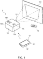
Fig. 1] Fig. 1 is a diagram showing a schematic configuration of a display system. - [
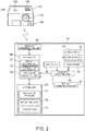
Fig. 2] Fig. 2 is a block diagram showing the configuration of a terminal apparatus. - [
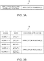
Fig. 3] Fig. 3 is a diagram showing a configuration example of NFC setting data. - [
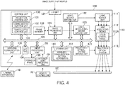
Fig. 4] Fig. 4 is a block diagram showing an example of the configuration of a projector. - [
Fig. 5] Fig. 5 is a diagram showing a specific configuration example of the projector. - [
Fig. 6] Fig. 6 is a flowchart showing the operations of the projector and the terminal apparatus. - [
Fig. 7] Fig. 7 is a diagram showing examples of images displayed on the display apparatus. - [
Fig. 8] Fig. 8 is a flowchart showing the operation of the projector in a modification. - An embodiment of the present invention is explained below with reference to the accompanying drawings.
- A schematic configuration of a
display system 1 in this embodiment is shown inFig. 1 . Thedisplay system 1 in this embodiment includes aterminal apparatus 10 functioning as an input apparatus and aprojector 100 functioning as a display apparatus. - The
terminal apparatus 10 is a small apparatus that a user holds and operates and is, for example, a portable apparatus such as a cellular phone such as a smartphone, a tablet terminal, or a PDA (Personal Digital Assistants). Theterminal apparatus 10 includes a flat terminal apparatusmain body 11. A display panel 52 (a display screen) is disposed on the surface of the terminal apparatusmain body 11. A touch screen 53 (Fig. 2 ) for detecting contact operation by the user is disposed on the surface of thedisplay panel 52. As shown inFig. 1 , thedisplay panel 52 is disposed to cover substantially the entire surface of one of widest surfaces of the terminal apparatusmain body 11. Thedisplay panel 52 in this embodiment has an elongated rectangular shape. The user can clearly distinguish a long side and a short side. Theterminal apparatus 10 may include various switches as other input devices of thetouch screen 53. - The
projector 100 projects image light on a projection target and forms an image on a surface of the projection target. The projection target on which theprojector 100 projects an image may be a plane or may be a curved surface or an uneven surface. However, in this embodiment, an example is explained in which theprojector 100 projects an image on a screen SC configured by a plane. A fixed plane such as a wall surface may be used as the screen SC. The screen SC may be a suspended or erected curtain-like screen.Fig. 1 shows a setting state of theprojector 100. Theprojector 100 includes a box-shaped projectormain body 101. Aprojection opening section 114 for projecting image light is provided on one surface of the projectormain body 101. Theprojection opening section 114 is an opening section from which a projection optical system 113 (Fig. 4 ) incorporated in the projectormain body 101 irradiates light. Anoperation panel 155 is disposed on the upper surface of the projectormain body 101. Theoperation panel 155 includes switches for operating theprojector 100 and indicator lamps indicating an operation state of theprojector 100. For example, theoperation panel 155 includes a power switch for switching the operation state of theprojector 100 to a normal operation state and a standby state (a power saving state). - The
projector 100 can be operated by aremote controller 70 that transmits an infrared signal. Theremote controller 70 may be an apparatus configuring thedisplay system 1 or may be not included in thedisplay system 1. Theremote controller 70 includes various switches for operating theprojector 100 and transmits a signal corresponding to operation of the switch to theprojector 100 as an infrared signal. - The
projector 100 includes an NFC (Near Field Communication)tag 158. The NFC tag 158 (a wireless tag) is an information storage medium called RFID (Radio Frequency Identifier) tag or wireless tag. TheNFC tag 158 stores various kinds of information in a ROM incorporated therein. The information stored by theNFC tag 158 can be read from the outside. TheNFC tag 158 may be an active tag that receives power supply from the inside of theprojector 100 or may be a passive tag that receives power supply from an apparatus that reads theNFC tag 158. In this embodiment, an example is explained in which theNFC tag 158 is configured as the passive tag. - The
NFC tag 158 is a tag conforming to a standard of NFC formulated as an ISO standard. However, an RFID tag of another type such as Felica (registered trademark) may be used. As the RFID tag, there are a tag that uses a radio signal in a 125 kHz band, a tag that uses a radio signal in a 13.56 MHz band, a tag that uses a radio signal in a UHF band (a 950 MHz band), a tag that uses a radio signal in a 2.45 GHz band, and the like. All of the tags can be used as theNFC tag 158. Note that, in this embodiment, an example is explained in which theNFC tag 158 is configured as a tag that is mounted on a smartphone and the like in many cases and uses a radio signal in the 13.56 MHz band. - The
NFC tag 158 is set on the rear side of the upper surface exterior of the projectormain body 101 or near the upper surface of the projectormain body 101 on the inside of the projectormain body 101. Therefore, when an apparatus having an NFC reading function approaches the upper surface of the projectormain body 101, the apparatus can read theNFC tag 158. Amarker 159 indicating a position near theNFC tag 158 is drawn on the upper surface of the projectormain body 101. Themarker 159 serves as a reference in reading theNFC tag 158. - In this embodiment, the screen SC has a rectangular shape. The
projector 100 is disposed on the front (the front surface) side of the screen SC. Theprojector 100 projects image light of a rectangular image (including a still image and a moving image). A rectangular projected image is formed on the screen SC. In the setting state shown inFig. 1 , theprojector 100 projects the image light upward from an oblique lower part of the screen SC. Therefore, a projected image formed on the screen SC is not rectangular. Trapezoidal distortion occurs in the projected image. - The
terminal apparatus 10 and theprojector 100 are connected to be capable of transmitting and receiving various data according to a wireless communication scheme. The wireless communication scheme is a short range wireless communication scheme such as a wireless LAN (Local Area Network), Bluetooth (registered trademark), or UWB (Ultra Wide Band) conforming to the IEEE802.11 standard. A wireless communication scheme that makes use of a cellular phone line may be adopted. - In this embodiment, a configuration is illustrated in which the
terminal apparatus 10 and theprojector 100 are connected by a wireless LAN and control data and content data explained below are transmitted and received by radio. - The
terminal apparatus 10 with which theprojector 100 communicates is not limited to one terminal apparatus. InFig. 1 , as an example, thedisplay system 1 including oneprojector 100 and oneterminal apparatus 10 is shown. - When establishing wireless communication, the
terminal apparatus 10 and theprojector 100 identify each other using information such as a MAC (Media Access Control) address, an SSID (Service Set IDentifier), an access point name, and a passphrase (a password) and are connected. These kinds of information are referred to as wireless communication setting information. In this embodiment, in a state in which theterminal apparatus 10 and theprojector 100 are capable of performing wireless communication, theterminal apparatus 10 searches for, on the basis of the wireless communication setting information, theprojector 100 present in a range in which wireless communication is possible. Therefore, theterminal apparatus 10 needs to have the wireless communication setting information of theprojector 100 in advance. - In the
display system 1, the wireless communication setting information of theprojector 100 is stored in theNFC tag 158. Therefore, theterminal apparatus 10 can obtain the wireless communication setting information for wireless connection to theprojector 100 by reading theNFC tag 158. If theterminal apparatus 10 and theprojector 100 establish wireless communication using the wireless communication setting information, thereafter, by transmitting a radio signal to theprojector 100, theterminal apparatus 10 can operate theprojector 100 as if theremote controller 70 is used. -
Fig. 2 is a block diagram showing the configuration of theterminal apparatus 10. - The
terminal apparatus 10 includes a control unit 20 (a terminal control unit) that controls the units of theterminal apparatus 10. Thecontrol unit 20 includes a CPU (Central Processing Unit), a ROM (Read Only Memory), a DRAM (Dynamic Random Access Memory), and the like not shown in the figure. Thecontrol unit 20 reads a basic control program stored in the ROM into the DRAM and executes the basic control program with the CPU to control theterminal apparatus 10. Thecontrol unit 20 executes programs stored in astoring unit 30 to thereby function as adisplay control unit 21, acommunication control unit 22, and anapplication executing unit 23 explained below (these units are hereinafter referred to as functional blocks). - The
terminal apparatus 10 includes the storingunit 30. The storingunit 30 is a nonvolatile storage device such as a flash memory or an EEPROM (Electrically Erasable and Programmable Read Only Memory) and is connected to thecontrol unit 20. The storingunit 30 stores various programs executed by thecontrol unit 20 and data. The storingunit 30 stores anapplication program 31,NFC setting data 32, andcontent data 33. - The
terminal apparatus 10 includes a wireless communication unit 40 (an inter-apparatus wireless communication unit). Thewireless communication unit 40 includes an antenna and an RF (Radio Frequency) circuit (not shown in the figure) and is connected to thecontrol unit 20. Thewireless communication unit 40 is controlled by thecontrol unit 20. Thewireless communication unit 40 transmits and receives various data to and from theprojector 100 according to the wireless communication scheme explained above. Thewireless communication unit 40 functions as a transmitting unit together with thecommunication control unit 22. - The
terminal apparatus 10 includes adisplay unit 51. Thedisplay unit 51 includes adisplay panel 52 and is connected to thecontrol unit 20. Thedisplay unit 51 draws, on the basis of image data input from thecontrol unit 20, a frame image adjusted to display resolution of thedisplay panel 52 in a drawing region secured in a not-shown DRAM to thereby cause thedisplay panel 52 to display an image. - The
terminal apparatus 10 includes thetouch screen 53, aswitch unit 54, and anoperation detecting unit 55. Thetouch screen 53 detects touch operation on thedisplay panel 52 and outputs a position signal indicating a detected operation position to theoperation detecting unit 55. Theoperation detecting unit 55 generates, on the basis of the position signal input from thetouch screen 53, coordinate information indicating a coordinate on thetouch screen 53 and outputs the coordinate information to thecontrol unit 20. - The
switch unit 54 includes operators such as switches provided separately from thetouch screen 53. When the switches are operated, theswitch unit 54 outputs an operation signal to theoperation detecting unit 55. Theoperation detecting unit 55 generates, on the basis of the operation signal input from theswitch unit 54, operation information corresponding to the operated operator and outputs the operation information to thecontrol unit 20. Thetouch screen 53 and theswitch unit 54 are equivalent to the operation unit. - The
control unit 20 can detect, on the basis of the coordinate information or the operation information input from theoperation detecting unit 55, contact operation on thedisplay panel 52, operation of the operators including the switches, and operation for moving the main body of theterminal apparatus 10. - The
terminal apparatus 10 includes an NFC tag communication unit 61 (a tag communication unit). The NFCtag communication unit 61 is a tag reader that reads an NFC tag conforming to the NFC standard and outputs data read from the NFC tag to thecontrol unit 20. The NFCtag communication unit 61 is capable of reading at least a passive tag. In a state in which theterminal apparatus 10 is operating and a reading operation of the NFCtag communication unit 61 is effective, theNFC tag 158 sends a radio signal for reading at every predetermined time. When induced power is generated in the NFC tag by the radio signal and the NFC tag transmits a radio signal, the NFCtag communication unit 61 receives the radio signal of the NFC tag, decodes the radio signal, and outputs received data to thecontrol unit 20. The NFCtag communication unit 61 may be a reader/writer apparatus capable of performing writing in the NFC tag in addition to reading of data from the NFC tag. - The
control unit 20 executes a basic control program stored in the storingunit 30 and performs basic control of the units of theterminal apparatus 10. The control is equivalent to an operating system of theterminal apparatus 10. Thedisplay control unit 21, thecommunication control unit 22, and theapplication executing unit 23 provide basic services to application programs running on the operating system. - The
display control unit 21 controls thedisplay unit 51 and causes thedisplay panel 52 to display various screens. Thedisplay control unit 21 reads out image data and the like stored in the storingunit 30 and outputs the image data and the like to thedisplay unit 51. Thedisplay unit 51 draws, on the basis of the input image data, a frame adjusted to display resolution of thedisplay panel 52 in a drawing region secured in a not-shown DRAM and drives thedisplay panel 52 on the basis of the drawn frame. - The
communication control unit 22 controls thewireless communication unit 40 to perform wireless communication with theprojector 100. Thecommunication control unit 22 executes transmission and reception of a wireless signal at a predetermined frequency and performs encoding of data to be transmitted and decoding of received data. - The
application executing unit 23 executes theapplication program 31 stored by the storingunit 30. - The storing
unit 30 can store a plurality ofapplication programs 31. Start conditions are set for therespective application programs 31. For example, when operation is performed on an icon displayed on thedisplay panel 52, theapplication program 31 associated with the operated icon is executed by theapplication executing unit 23. Theapplication executing unit 23 selects and executes theapplication program 31 corresponding to operation of thetouch screen 53, operation of theswitch unit 54, or data read from the NFC tag by the NFCtag communication unit 61. - The
NFC setting data 32 decides theapplication program 31 started when the NFCtag communication unit 61 reads data from the NFC tag. Theapplication executing unit 23 refers to the data read by the NFCtag communication unit 61 and theNFC setting data 32 and selects and executes theapplication program 31 corresponding to the read data. - A specific configuration example of the
NFC setting data 32 is shown inFig. 3 . -
Fig. 3(A) is a schematic diagram showing a first configuration example of theNFC setting data 32.Fig. 3(B) is a schematic diagram showing a second configuration example of theNFC setting data 32. - The first configuration example shown in
Fig. 3(A) is a simplest configuration of theNFC setting data 32. TheNFC setting data 32 decides oneapplication program 31 started when the NFCtag communication unit 61 reads data from the NFC tag. In the example shown in the figure, an application program (1) is registered as an application program to be executed. - In this case, when interruption indicating the reading of the data is performed on the
control unit 20 from the NFCtag communication unit 61, theapplication executing unit 23 executes one application program 31 (the application program (1)) designated by theNFC setting data 32. - The
NFC setting data 32 of the second configuration example shown inFig. 3(B) associates content of data read from the NFC tag by the NFCtag communication unit 61 with each of the plurality ofapplication programs 31. - For example, when data readably retained by the
NFC tag 158 includes data serving as a clue for classifying a model of theprojector 100, theapplication program 31 to be executed can be selected in association with the model. In the example shown inFig. 3(B) , theapplication executing unit 23 selects a moresuitable application program 31 on the basis of the data serving as the clue for classifying the model of theprojector 100 read from theNFC tag 158 by the NFCtag communication unit 61. As selection conditions, for example, the application program (1) is selected when the data of theNFC tag 158 has a "group 1" and does not have a "group 2" and an application program (2) is selected when the data of theNFC tag 158 has the "group 2". As shown inFig. 3(B) , it is assumed that theNFC tag 158 of models "1-A", "1-B", and "2-A" of theprojector 100 has only the data of the "group 1", theNFC tag 158 of a model "2-B" of theprojector 100 has only the data of the "group 2", and theNFC tag 158 of a model "2-C" of theprojector 100 has the data of the "group 1" and the "group 2". In this case, when the model of theprojector 100 is "1-A", "1-B", or "2-A", the application program (1) is selected. When the model of theprojector 100 is "2-B" or "2-C", the application program (2) is selected. In this way, the selection conditions for the application program (1) and the application program (2) are associated with the data stored in theNFC tag 158. Consequently, theapplication executing unit 23 can execute theapplication program 31 corresponding to the model. By adopting this method, even if a name itself of an application program is not stored in the NFC tag, the application program to be executed can be selected according to data representing characteristics of the model of theprojector 100. Therefore, it is possible to more flexibly select an optimum application program. - The
content data 33 includes moving image (video) data and still image data and is data of contents reproducible by theprojector 100. Thecontent data 33 may include a plurality of moving image or still image data or may include sound data. When content data is transmitted by a function of theapplication program 31 executed by theapplication executing unit 23, theapplication program 31 reads out thecontent data 33 and transmits thecontent data 33 with thewireless communication unit 40. -
Fig. 4 is a block diagram showing the configuration of theprojector 100. - The
projector 100 includes an interface unit (hereinafter abbreviated as I/F) 124. Theprojector 100 is connected to an image supply apparatus via the I/F unit 124. As the I/F unit 124, for example, a DVI interface to which a digital video signal is input, a USB interface, and a LAN interface can be used. As the I/F unit 124, for example, an S video terminal to which a composite video signal such as NTSC, PAL, or SECAM is input, an RCA terminal to which a composite video signal is input, and a D terminal to which a component video signal is input can be used. Further, as the I/F unit 124, a general-purpose interface such as an HDMI connector conforming to an HDMI (registered trademark) standard can be used. The I/F unit 124 may include an A/D conversion circuit that converts an analog video signal into digital image data and may be connected to the image supply apparatus by an analog video terminal such as a VGA terminal. Note that the I/F unit 124 may perform transmission and reception of an image signal through wired communication and may perform transmission and reception of an image signal through wireless communication. - The
projector 100 roughly includes a projecting unit 110 (a display unit) that performs formation of an optical image and an image processing system that electrically processes an image signal input to the projectingunit 110. The projectingunit 110 includes alight source unit 111, alight modulating device 112 including aliquid crystal panel 112A, and a projectionoptical system 113. - The
light source unit 111 includes a light source such as a xenon lamp, an ultra-high pressure mercury lamp, an LED (Light Emitting Diode), or a laser. Thelight source unit 111 may include a reflector and an auxiliary reflector that guide light emitted by the light source to thelight modulating device 112. Thelight source unit 111 may include a lens group (not shown in the figure) for improving an optical characteristic of projected light, a sheet polarizer, or a dimming element for reducing, on a path leading to thelight modulating device 112, a light amount of the light emitted by the light source. - The
light modulating device 112 includes, for example, aliquid crystal panel 112A of a transmission type. Theliquid crystal panel 112A receives a signal from an image processing system explained below and forms an image. In this case, thelight modulating device 112 includes threeliquid crystal panels 112A corresponding to the three primary colors of RGB in order to perform color projection. Light from thelight source unit 111 is separated into color lights of three colors of RGB. The color lights are made incident on theliquid crystal panels 112A corresponding to the color lights. The color lights passed through theliquid crystal panels 112A to be modulated are combined by a combination optical system such as a cross dichroic prism and emitted to the projectionoptical system 113. - Note that the
light modulating device 112 is not limited to the configuration including the threeliquid crystal panels 112A of the transmission type. For example, three liquid crystal panels of a reflection type can also be used. Thelight modulating device 112 can also be configured by, for example, a method of combining one liquid crystal panel and color wheels, a method of using three DMDs (Digital Mirror Devices), or a method of combining one DMD and color wheels. When only oneliquid crystal panel 112A or DMD is used as thelight modulating device 112, a member equivalent to the combination optical system such as the cross dichroic prism is unnecessary. Besides theliquid crystal panel 112A and the DMD, a component capable of modulating light emitted by the light source can also be adopted without a problem. - The projection
optical system 113 irradiates the incident light modulated by thelight modulating device 112 toward the outside from the projection opening section 114 (Fig. 1 ) using a projection lens and forms a projected image on the screen SC. - A projection-optical-
system driving unit 121 that drives motors included in the projectionoptical system 113 according to the control by acontrol unit 130 and a light-source driving unit 122 that drives the light source included in thelight source unit 111 according to the control by thecontrol unit 130 are connected to the projectingunit 110. The projection-optical-system driving unit 121 and the light-source driving unit 122 are connected to abus 105. - The
projector 100 includes awireless communication unit 156. Thewireless communication unit 156 is connected to thebus 105. Thewireless communication unit 156 includes an antenna and an RF (Radio Frequency) circuit not shown in the figure. Thewireless communication unit 156 communicates with theterminal apparatus 10 according to a wireless communication standard under the control by thecontrol unit 130. Theprojector 100 and theterminal apparatus 10 are connected to be capable of transmitting and receiving various data according to the wireless communication scheme. - The
NFC tag 158 of theprojector 100 is connected to thebus 105. When electric power is supplied by a radio signal for reading emitted by theterminal apparatus 10, theNFC tag 158 interrupts thecontrol unit 130. - The image processing system included in the
projector 100 is configured mainly from thecontrol unit 130 that integrally controls theentire projector 100. Besides, the image processing system includes astoring unit 151, animage processing unit 125, a light-modulating-device driving unit 123, and aninput processing unit 153. Thecontrol unit 130, the storingunit 151, theinput processing unit 153, theimage processing unit 125, and the light-modulating-device driving unit 123 are respectively connected to thebus 105. - The
control unit 130 includes a CPU, a ROM, a RAM, and a DRAM not shown in the figure. Thecontrol unit 130 reads out a basic control program stored in the ROM to the RAM or the DRAM, executes the basic control program with the CPU, and controls theprojector 100. Thecontrol unit 130 executes theapplication program 31 stored in thestoring unit 151 to thereby function as aprojection control unit 131, acommunication control unit 132, and a power-supply control unit 133 explained below. - The storing
unit 151 is a nonvolatile memory such as a flash memory or an EEPROM. The storingunit 151 stores a control program used for the control of theprojector 100, image data, and the like. - The storing
unit 151 stores wirelesscommunication setting information 161. The wirelesscommunication setting information 161 includes at least one of the wireless communication setting information stored by theNFC tag 158. The wirelesscommunication setting information 161 may include the entire wireless communication setting information of theNFC tag 158. The wireless communication setting information stored by theNFC tag 158 may be copied to thestoring unit 151 according to the control by thecontrol unit 130. - The
image processing unit 125 executes, for example, resolution conversion processing for converting image data input from the I/F unit 124 into data having resolution matching the specifications of theliquid crystal panel 112A of thelight modulating device 112. Theimage processing unit 125 draws, in theframe memory 126, an image for display displayed by thelight modulating device 112 and outputs the drawn image for display to the light-modulating-device driving unit 123. The light-modulating-device driving unit 123 drives thelight modulating device 112 on the basis of the image for display input from theimage processing unit 125. Consequently, an image is drawn on theliquid crystal panel 112A of thelight modulating device 112. The drawn image is projected on the screen SC as a projected image via the projectionoptical system 113. - The
image processing unit 125 executes correction processing for correcting trapezoidal distortion of the projected image by deforming the image drawn in theframe memory 126. In the correction processing, so-called barrel distortion (pin-cushion distortion) may be corrected. Theimage processing unit 125 may execute deformation processing such as enlargement, reduction, and rotation of the image. - In the
projector 100, theoperation panel 155 is disposed on the upper surface of the projector main body 101 (Fig. 1 ). Theoperation panel 155 is connected to theinput processing unit 153. Theinput processing unit 153 appropriately lights or flashes the indicator lamps of theoperation panel 155 according to the control by thecontrol unit 130 and according to an operation state and a setting state of theprojector 100. When the switch of theoperation panel 155 is operated, an operation signal corresponding to the operated switch is output to thecontrol unit 130 from theinput processing unit 153. - The
projector 100 includes an infrared-light receiving unit 154 (an infrared communication unit) that receives a signal from theremote controller 70 used by the user. For example, as shown inFig. 2 , the infrared-light receiving unit 154 is set on the front surface of the projectormain body 101 and receives an infrared signal emitted by theremote controller 70. The infrared-light receiving unit 154 decodes the infrared signal received from theremote controller 70, generates an operation signal indicating operation content in theremote controller 70, and outputs the operation signal to thecontrol unit 130. - Functional blocks included in the
control unit 130 are explained. - The
projection control unit 131 controls theimage processing unit 125 to draw an image in theframe memory 126 on the basis of image data supplied from the image supply apparatus via the I/F unit 124. When thecommunication control unit 132 receives content data from theterminal apparatus 10, theprojection control unit 131 controls theimage processing unit 125 to draw an image in theframe memory 126 based on the content data. Theprojection control unit 131 controls the light-modulating-device driving unit 123 to draw the image drawn in theframe memory 126 on theliquid crystal panel 112A of thelight modulating device 112. The image drawn on theliquid crystal panel 112A of thelight modulating device 112 is projected on the screen SC as a projected image via the projectionoptical system 113. - The
communication control unit 132 controls thewireless communication unit 40 to perform wireless communication with theterminal apparatus 10. Thecommunication control unit 132 establishes wireless communication with theterminal apparatus 10, receives control data and content data transmitted by theterminal apparatus 10, and processes the received data. For example, when thecommunication control unit 132 receives content data, the content data is temporarily stored in the RAM of thecontrol unit 130 or thestoring unit 151 and projected on the screen SC by theprojection control unit 131. - The power-
supply control unit 133 switches the operation state of theprojector 100 to the normal operation state and the standby state. In the normal operation state, the power-supply control unit 133 brings the components included in theprojector 100 into at least a state in which projection by the projectingunit 110 is possible. That is, electric power is supplied to the units of the projectingunit 110 and the units configuring the image processing system. The normal operation state includes a state in which the light source of thelight source unit 111 is extinguished or the luminance of the light source is reduced in a state in which there is no image projected by the projectingunit 110. - The standby state is at least a state in which the
control unit 130, theinput processing unit 153, and the infrared-light receiving unit 154 operate and operation of the power switch and an infrared signal from theremote controller 70 can be detected. It is possible to turn off power supply to the units of the projectingunit 110, the projection-optical-system driving unit 121, the light-source driving unit 122, the light-modulating-device driving unit 123, theimage processing unit 125, and theframe memory 126 or bring the power supply into a low power state. It is possible to turn off power supply to thestoring unit 151 and thewireless communication unit 156 or bring the power supply into a low power state. In this embodiment, the power supply to thewireless communication unit 156 is turned off in the standby state. Therefore, power consumption of theprojector 100 in the standby state is low compared with the power consumption in the normal operation state. - In
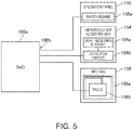
Fig. 5 , a specific configuration example is shown concerning a main part of the control system of theprojector 100. - An SoC (System on Chip) 100a shown in
Fig. 5 is an integrated circuit in which a part of the functional blocks shown inFig. 4 are integrated. At least thecontrol unit 130 and theinput processing unit 153 are implemented in theSoC 100a. The storingunit 151 may be included in theSoC 100a. Theimage processing unit 125 and theframe memory 126 may be implemented in theSoC 100a. Further, the projection-optical-system driving unit 121, the light-source driving unit 122, and the light-modulating-device driving unit 123 may be implemented. These units are implemented as, for example, an IP core of theSoC 100a. - In the standby state, the
SoC 100a stops a part of a CPU core or keeps an operating frequency low to thereby change to a state in which power consumption is lower than the power consumption in the normal operation state. In the standby state, theSoC 100a is capable of detecting interruption from the infrared-light receiving unit 154, theoperation panel 155, and theNFC tag 158 connected to an interruption terminal (a signal input terminal having a function of detecting an interruption signal) 100b. - In the standby state, when detecting an input of an interruption signal to the
interruption terminal 100b, specifically, a change in the potential of theinterruption terminal 100b, theSoC 100a returns to the normal operation state. The infrared-light receiving unit 154 includes, as shown inFig. 5 , alight receiving element 154a configured by a phototransistor or a photodiode and adetection circuit 154b that detects a light receiving state of thelight receiving element 154a. Thedetection circuit 154b drives thelight receiving element 154a. When a light reception pattern of infrared light detected by thelight receiving element 154a matches a pattern of a transmission signal of theremote controller 70, thedetection circuit 154b inputs an interruption signal to theinterruption terminal 100b. - The
operation panel 155 includes aswitch board 155a connected to the various switches explained above. For example, a mechanical switch conducting according to operation of a switch can be implemented on theswitch board 155a. Theswitch board 155a can be configured by a flat switch in which printed wires conduct one another. Theswitch board 155a is energized according to the operation of the switch to input an interruption signal to theinterruption terminal 100b. Note that, concerning all the switches included in theoperation panel 155, theswitch board 155a does not have to output the interruption signal during operation. For example, in the standby state of theSoC 100a, theswitch board 155a may be configured to input the interruption signal to theinterruption terminal 100b when the power switch of theoperation panel 155 is operated and not to input the interruption signal even if the other switches are operated. - The
NFC tag 158 includes anantenna 158a and atag IC 158b. An induced current flows to theantenna 158a according to a radio signal emitted by an apparatus (e.g., the terminal apparatus 10) that reads theNFC tag 158. Thetag IC 158b starts using the induced current as a power supply. Thetag IC 158b includes a ROM that stores wireless communication setting information and the like and a control unit that executes wireless communication by theantenna 158a. Thetag IC 158b starts operation when the induced current of theantenna 158a flows, executes wireless communication with theterminal apparatus 10 and the like, and transmits the wireless communication setting information and the like. When starting with the induced current of theantenna 158a, thetag IC 158b inputs an interruption signal to theinterruption terminal 100b. - An interruption signal is input to the
SoC 100a when any one of the following events occurs in the standby state: the infrared-light receiving unit 154 receives an infrared signal of theremote controller 70, the switch of theoperation panel 155 is operated, and theNFC tag 158 is read. TheSoC 100a only has to be capable of detecting an interruption signal of theinterruption terminal 100b in the standby state. TheSoC 100a can stop the components related to the other functions and effectively reduce power consumption. - The power-
supply control unit 133 controls a power supply state to theSoC 100a and the other units of theprojector 100 and controls a shift to the standby state and return from the standby state to the normal operation state. A trigger of the shift from the normal operation state to the standby state is, for example, an input state of image data to the I/F unit 124, operation of theoperation panel 155, operation by theremote controller 70, and control data received by thewireless communication unit 156. A trigger of the return from the standby state to the normal operation state is an input of an interruption signal to theinterruption terminal 100b as explained above. - In the
display system 1, when operation for bringing theterminal apparatus 10 close to the projectormain body 101 is performed, the NFCtag communication unit 61 of theterminal apparatus 10 performs reading of theNFC tag 158. At this point, when an induced current flows to theantenna 158a according to a radio signal emitted by the NFCtag communication unit 61, an interruption signal is input to theinterruption terminal 100b. Therefore, when theterminal apparatus 10 is brought close to theprojector 100 in the standby state, theprojector 100 returns from the standby state to the normal operation state. - Consequently, power supply to the
wireless communication unit 156 of theprojector 100 is started and thewireless communication unit 156 changes to a wirelessly communicable state. Therefore, theprojector 100 and theterminal apparatus 10 can establish wireless communication. - That is, even if the
projector 100 stops thewireless communication unit 156 in the standby state, when theterminal apparatus 10 reads theNFC tag 158, theprojector 100 can establish wireless communication with theterminal apparatus 10. In this case, operation for returning theprojector 100 from the standby state to the normal operation state beforehand is not performed. Therefore, it is possible to quickly connect theprojector 100 and theterminal apparatus 10 with simple operation and reduce power consumption of theprojector 100. -
Fig. 6 is a flowchart showing the operation of thedisplay system 1.Fig. 6(A) shows the operation of theprojector 100.Fig. 6(B) shows the operation of theterminal apparatus 10. - At a start point in time of the operation shown in
Fig. 6 , theprojector 100 is in the standby state. - The
projector 100 stands by for an interruption signal to theinterruption terminal 100b (step S11). Theprojector 100 stops power supply to the units and maintains the standby state until the interruption signal is input (No in step S11). - When the user holds the
terminal apparatus 10 in a hand, brings theterminal apparatus 10 close to the upper surface of the projectormain body 101, and performs reading of the NFC tag 158 (step S21), the interruption signal is input to theinterruption terminal 100b in the projector 100 (Yes in step S11). - The
projector 100 returns to the normal operation state in response to the interruption signal (step S12). Consequently, thewireless communication unit 156 starts (step S13). - On the other hand, the
terminal apparatus 10 acquires information from theNFC tag 158 with the NFC tag communication unit 61 (step S22). The information acquired in step S22 includes wireless communication setting information. Theterminal apparatus 10 selects, on the basis of the acquired information, theapplication program 31 to be started referring to the NFC setting data 32 (step S23). - In the
terminal apparatus 10, when the selectedapplication program 31 is executed (step S24), wireless communication is established on the basis of the wireless communication setting information acquired in step S22 according to the function of the application program 31 (step S25). In theprojector 100, thewireless communication unit 156 operates to establish wireless communication with the terminal apparatus 10 (step S14). - The
terminal apparatus 10 displays an operation screen according to the function of the application program 31 (step S26) and stands by for operation (No in step S27). The operation screen is a screen on which icons and the like simulating switches for operation are disposed. When the icons and the like are touched, theterminal apparatus 10 detects the operation on thetouch screen 53. When detecting the operation (Yes in step S27), theterminal apparatus 10 generates control data corresponding to operation and transmits the control data to theprojector 100 with the wireless communication unit 40 (step S28). - The
terminal apparatus 10 determines whether the operation detected in step S27 is an instruction for an end of the operation of the application program 31 (step S29). When the operation is not the instruction for the end (No in step S29), theterminal apparatus 10 returns to step S27 and stands by for the next operation. When the operation is the instruction for the end (Yes in step S29), theterminal apparatus 10 ends the execution of theapplication program 31, disconnects the wireless connection to the projector 100 (step S30), and ends the processing. - The
projector 100 receives the control data transmitted by the terminal apparatus 10 (step S15) and determines whether the received control data is data for instructing an end of the operation of theprojector 100 by the terminal apparatus 10 (step S16). When the control data is not the data for instructing the end (No in step S16), theprojector 100 executes processing corresponding to the control data (step S17), returns to step S15, and stands by for reception of the next control data. - When the control data received from the
terminal apparatus 10 is the instruction for the end (Yes in step S16), theprojector 100 shifts to the standby state (step S18) and ends the processing. -
Fig. 7 is a diagram showing examples of images displayed on thedisplay panel 52 of theterminal apparatus 10.Fig. 7(A) shows an example of an operation screen.Figs. 7(B) and 7(C) show other examples of the operation screen.Fig. 7(D) shows an example of a display screen in the case in which transmission of thecontent data 33 is instructed on the operation screen. Operation screens 63, 64, and 65 and acontent reproduction screen 66 shown inFigs. 7(A) to 7(D) are displayed when theapplication executing unit 23 executes theapplication program 31. - In the
operation screen 63 shown inFig. 7(A) , afunction icon group 63a is disposed in an upper part of thedisplay panel 52 and adirection indicator icon 63b are disposed in the center of thedisplay panel 52. Thefunction icon group 63a includes icons corresponding to functions such as power-off of theprojector 100, switching of an image source projected by theprojector 100, and sound volume adjustment. The icon of the power-off corresponds to the instruction for the end of the operation by theapplication program 31. Thedirection indicator icon 63b is used for sound volume adjustment, selection of candidates displayed as a list, and the like. - In
Figs. 7(B) and 7(C) , examples of operation screens suitable for the operation of theprojector 100 having more functions are shown. Theoperation screen 63 shown inFig. 7(A) includes thefunction icon group 63a including three icons and thedirection indicator icon 63b. However, when theprojector 100 having more functions is operated, theterminal apparatus 10 desirably displays more icons. In such a case, for example, anoperation screen 64 shown inFig. 7(B) is displayed on theterminal apparatus 10. - On the
operation screen 64, theicon group 63a and thedirection indicator icon 63b same as those displayed on theoperation screen 63 are disposed. Further, apage switching icon 64c is disposed on theoperation screen 64. When thepage switching icon 64c is operated, a display screen transitions to anoperation screen 65 shown inFig. 7(C) . On theoperation screen 65, thedirection indicator icon 63b is disposed. Besides, a function icon group 63d including function icons different from thefunction icon group 63a is disposed. Apage switching icon 65c for instructing transition to theoperation screen 64 shown inFig. 7(B) is disposed. - In this way, the
terminal apparatus 10 can enable, according to the function of theapplication program 31, operation by a large number of icons using the operation screens 64 and 65 configured by pluralities of pages. - The
operation screen 63 is suitable for theprojector 100 having fewer functions. The operation screens 64 and 65 are suitable for theprojector 100 having more functions. Therefore, theterminal apparatus 10 desirably switches and displays theoperation screen 63 and the operation screens 64 and 65 according to a model of theprojector 100. As a method for realizing the display, in this embodiment, three methods are illustrated. - A first method is a method in which the
application program 31 of theterminal apparatus 10 switches and displays a different operation screen according to a model of theprojector 100. In this case, theapplication program 31 determines the model of theprojector 100 on the basis of wireless communication setting information acquired by the NFCtag communication unit 61 and selects an operation screen corresponding to the determined model. For example, theapplication program 31 is capable of displaying theoperation screen 63 and the operation screens 64 and 65. Theapplication program 31 selects and displays either one of the operation screens according to the model of theprojector 100. In this method, thecommon application program 31 can be used irrespective of the model of theprojector 100. Therefore, there is an advantage that it is easy to manage theapplication program 31. - A second method is a method in which, as shown in
Fig. 3(B) , theterminal apparatus 10 stores the plurality ofapplication programs 31 in the storingunit 30 and starts adifferent application program 31 according to a model of theprojector 100. Therespective application programs 31 have different operation screens. For example, the application program (1) shown inFig. 3(B) displays theoperation screen 63 and the application program (2) displays the operation screens 64 and 65. In this method, the user only has to install, in theterminal apparatus 10, theapplication program 31 corresponding to the model of theprojector 100 in use. Therefore, there is an advantage that it is possible to reduce a data volume of theapplication program 31 stored by the storingunit 30. - A third method is a method in which the NFC
tag communication unit 61 invokes another application program according to an application program started after reading theNFC tag 158. An application program started first does not have a function of displaying an operation screen, determines a model of theprojector 100 on the basis of wireless communication setting information, and invokes another application program corresponding to the determined model. There are a plurality of application programs to be invoked. The application programs can respectively display different operation screens. For example, either one of theapplication program 31 for displaying theoperation screen 63 and theapplication program 31 for displaying the operation screens 64 and 65 is selected and invoked. In this method, it is possible to easily realize processing for selecting theapplication program 31 according to the model of theprojector 100 even if the processing is complicated. Therefore, there is an advantage that it is possible to easily cope with enhancement, high functionality, and diversification of models of theapplication program 31. - It is possible to transmit the
content data 33 stored by theterminal apparatus 10 to theprojector 100 according to operation by the operation screens 63, 64, 65, and the like and cause theprojector 100 to display thecontent data 33. An example of a screen during the transmission and the display of thecontent data 33 is shown inFig. 7(D) . On thecontent reproduction screen 66, a video or an image being reproduced is displayed on the full screen. Besides, ascreen switching icon 66a is disposed to enable operation on theprojector 100. When thescreen switching icon 66a is operated, the displayed screen is switched to the operation screens 63, 64, 65, and the like. Thescreen switching icon 66a is desirably displayed at a corner of thedisplay panel 52 not to hinder viewing of the image. - As explained above, the
display system 1 according to this embodiment includes theterminal apparatus 10 and theprojector 100. Theprojector 100 includes the projectingunit 110 that displays an image. Theprojector 100 includes theNFC tag 158, thewireless communication unit 156 that performs wireless communication with theterminal apparatus 10, and thecontrol unit 130 that switches the operation state of theprojector 100 to at least the normal operation state and the standby state. When detecting that theNFC tag 158 communicates with theterminal apparatus 10 in the standby state, thecontrol unit 130 shifts the operation state to the normal operation state. Thewireless communication unit 156 returns from the standby state to the normal operation state and establishes wireless communication with theterminal apparatus 10. Consequently, when theprojector 100 is in the standby state, by performing operation for reading theNFC tag 158, it is possible to quickly start wireless communication between theprojector 100 and theterminal apparatus 10. Therefore, it is possible to reduce power consumption of theprojector 100 while wireless communication is not established and connect theterminal apparatus 10 and theprojector 100 without performing complicated operation. - The
NFC tag 158 retains at least wireless communication setting information related to wireless communication of thewireless communication unit 156. Thewireless communication unit 156 establishes wireless communication with theterminal apparatus 10 using the wireless communication setting information retained by theNFC tag 158. Therefore, it is possible to quickly establish wireless communication on the basis of the information retained byNFC tag 158. - The
NFC tag 158 can store, for example, data (identification information) for identifying a model as a type of theprojector 100. Therefore, theterminal apparatus 10 can identify the model of theprojector 100. Consequently, theterminal apparatus 10 can perform processing corresponding to the model of theprojector 100. - The
control unit 130 enables power supply to thewireless communication unit 156 and the projectingunit 110 in the normal operation state and turns off the power supply to thewireless communication unit 156 and the projectingunit 110 and stands by for communication of theNFC tag 158 in the standby state. Therefore, in the standby state, it is possible to enable standby for reading of theNFC tag 158 and reduce power consumption. - The
projector 100 includes the infrared-light receiving unit 154 that receives an infrared signal. Thecontrol unit 130 enables reception of the infrared signal by the infrared-light receiving unit 154 in the standby state. Therefore, in the standby state, it is possible to stand by for both of reading of theNFC tag 158 and operation of theremote controller 70. - The
terminal apparatus 10 includes the NFCtag communication unit 61 that reads theNFC tag 158, thewireless communication unit 40 that performs wireless communication with theprojector 100, and the storingunit 30 that stores theapplication program 31. Theterminal apparatus 10 establishes, with thecontrol unit 20, wireless communication with theprojector 100 in thewireless communication unit 40 on the basis of information read from theNFC tag 158 by the NFCtag communication unit 61. Further, thecontrol unit 20 reads out, from the storingunit 30, theapplication program 31 corresponding to the information read from theNFC tag 158 and executes theapplication program 31 and transmits control data for controlling theprojector 100 from thewireless communication unit 40. Consequently, it is possible to establish wireless communication between theprojector 100 and theterminal apparatus 10 with simple operation for reading theNFC tag 158 and thereafter operate theprojector 100 according to the function of theapplication program 31. - The
terminal apparatus 10 includes the projectingunit 110 that displays a screen and thetouch screen 53 and theswitch unit 54 that receive operation. Thecontrol unit 20 displays, according to the function of theapplication program 31, with the projectingunit 110, an operation screen for controlling theprojector 100 and transmits control data on the basis of operation detected by the operation unit during the display of the operation screen. Consequently, it is possible to operate theprojector 100 using, for example, the operation screens 63, 64, and 65 shown inFigs. 7(A) to 7(C) . Therefore, it is possible to operate theprojector 100 even if theremote controller 70 exclusive for theprojector 100 is not used. Theterminal apparatus 10 may be, for example, a smartphone carried by the user. Therefore, it is possible to operate various projectors with the smartphone carried by the user without using theremote controller 70. - The
control unit 20 may be capable of executing the plurality ofapplication programs 31 for respectively displaying different operation screens with the projectingunit 110. In this case, thecontrol unit 20 may select, on the basis of information read from theNFC tag 158 by the NFCtag communication unit 61, theapplication program 31 to be executed. In this case, it is possible to properly use the plurality of kinds of operation screens 63, 64, and 65 according to the plurality ofapplication programs 31. - The
control unit 20 may be capable of displaying a plurality of operation screens according to the function of theapplication program 31. Thecontrol unit 20 may display, on thedisplay panel 52, an operation screen corresponding to information read from theNFC tag 158 by the NFCtag communication unit 61. Thecontrol unit 20 may execute an application program when theNFC tag 158 is read by the NFCtag communication unit 61 and invoke and start, according to a function of the application program, theapplication program 31 for displaying an operation screen. - As explained above, after detecting with an interruption signal that the
NFC tag 158 is read, theprojector 100 shifts from the standby state to the normal operation state. When a state in which thewireless communication unit 156 does not establish wireless communication with theterminal apparatus 10 continues, theprojector 100 may shift to the standby state. -
Fig. 8 is a flowchart showing the operation of theprojector 100 in a modification of this embodiment. The operation shown inFig. 8 can be executed instead of the operation shown inFig. 6(A) . Kinds of processing same as the kinds of processing shown inFig. 6(A) are denoted by the same step numbers and explanation of the kinds of processing is omitted. - The
projector 100 returns to the normal operation state in response to an interruption signal (step S12), starts the wireless communication unit 156 (step S13), and thereafter determines whether a radio signal is received (step S41). In step S41, theprojector 100 determines whether theterminal apparatus 10 can receive a radio signal transmitted to establish wireless communication. - When the wireless signal is received (step S41), the
projector 100 shifts to step S14 and establishes wireless communication. - On the other hand, when the radio signal is not received (No in step S41), the
projector 100 determines whether a time set in advance has elapsed after thewireless communication unit 156 is turned on (step S42). When the set time has not elapsed (No in step S42), theprojector 100 returns to step S41. When the time set in advance has elapsed (Yes in step S42), theprojector 100 shifts to step S18 and returns to the standby state. - In this operation, even if the
projector 100 detects that theNFC tag 158 is read, if wireless communication is not established between theprojector 100 and theterminal apparatus 10, theprojector 100 returns to the standby state. Therefore, even if theNFC tag 158 is read, it is possible to reduce power consumption in the case in which it is unnecessary to shift to the normal operation state. Specifically, the user erroneously reads theNFC tag 158 and ends theapplication program 31 or theterminal apparatus 10 not installed with theapplication program 31 reads theNFC tag 158. In such a case, operation for shifting theprojector 100 to the standby state again is unnecessary. Therefore, it is possible to achieve further improvement of convenience. - Note that the embodiment explained above indicates an example of a preferred embodiment of the present invention. Embodiments of the present invention are not limited to this embodiment. Various modified implementations are possible within a range not departing from the spirit of the present invention. For example, the configuration is explained in which one
terminal apparatus 10 performs wireless communication with oneprojector 100 and performs operation. However, a plurality ofterminal apparatuses 10 may control one or a plurality ofprojectors 100. A plurality ofprojectors 100 may be controlled by oneterminal apparatus 10. Further, theprojector 100 may be configured to be capable of identifying theterminal apparatus 10. - For example, in the embodiment explained above, the
projector 100 of a front projection type that projects an image from the front of the screen SC is explained as an example of the display apparatus. However, the present invention is not limited to this. For example, a projector of a rear projection type that projects an image from the rear side of the screen SC can be adopted as the display apparatus. A liquid crystal monitor or a liquid crystal television that displays an image on a liquid crystal display panel may be adopted as the display apparatus. A PDP (Plasma Display Panel), a CRT (Cathode Ray Tube) display, an SED (Surface-conduction Electron-emitter Display), or the like may be used as the display apparatus. A monitor apparatus that displays an image on an organic EL display panel called OLED (Organic light-emitting diode), OEL (Organic Electro Luminescence) display, or the like or a self-emitting display apparatus such as a television receiver may be adopted. When the present invention is applied in configurations including these display apparatuses, as in the embodiment, it is possible to obtain useful effects. - As the terminal apparatus functioning as the input apparatus of the present invention, in this embodiment, the portable
terminal apparatus 10 including the flat terminal apparatusmain body 11 and held in the hand and operated by the user is explained as the example. However, the present invention is not limited to this. For example, a portable game machine, a portable reproducing apparatus for reproducing music and videos, and the like can be used as theterminal apparatus 10. Further, theterminal apparatus 10 may be configured to include a hardware keyboard or the like other than thedisplay panel 52. - The
NFC tag 158 is explained as being set in the projectormain body 101. However, theNFC tag 158 may be set in a housing separate from the projectormain body 101. In this case, the separate housing and the projectormain body 101 are connected by a cable. Consequently, it is possible to dispose theNFC tag 158 in a position apart from the projector main body. Therefore, convenience of use is higher. - The functional units shown in
Fig. 2 andFig. 4 indicate functional components and specific implementation forms of the functional units are not particularly limited. That is, hardware individually corresponding to the functional units does not always need to be implemented. It is naturally possible that one processor is configured to execute a program to realize functions of a plurality of functional units. A part of the functions realized by software in the embodiment may be realized by hardware. Alternatively, a part of the functions realized by hardware may be realized by software. Besides, it is also possible to optionally change specific detailed configurations of the other units of thedisplay system 1 in a range not departing from the spirit of the present invention. -
- 1
- display system
- 10
- terminal apparatus
- 20
- control unit (terminal control unit)
- 21
- display control unit
- 22
- communication control unit
- 23
- application executing unit
- 30
- storing unit
- 31
- application program
- 32
- NFC setting data
- 33
- content data
- 40
- wireless communication unit (inter-apparatus wireless communication unit)
- 51
- display unit
- 52
- display panel
- 53
- touch screen
- 54
- switch unit
- 55
- operation detecting unit
- 61
- NFC tag communication unit (tag communication unit)
- 63, 64, 65
- operation screen
- 63a,
- 63d function icon group
- 63b
- direction indicator icon
- 64c, 65c
- page switching icon
- 66
- content reproduction screen
- 66a
- screen switching icon
- 70
- remote controller
- 100
- projector (display apparatus)
- 100a
- SoC
- 100b
- interruption terminal
- 110
- projecting unit (display unit)
- 130
- control unit
- 131
- projection control unit
- 132
- communication control unit
- 133
- power-supply control unit
- 151
- storing unit
- 153
- input processing unit
- 154
- infrared-light receiving unit
- 154a
- light receiving element
- 154b
- detection circuit
- 155
- operation panel
- 155a
- switch board
- 156
- wireless communication unit
- 158
- NFC tag (wireless tag)
- 158a
- antenna
- 158b
- tag IC
- 159
- marker
- 161
- wireless communication setting information
- SC
- screen
Claims (12)
- A display apparatus comprising:a display unit configured to display an image;a wireless tag;a wireless communication unit configured to perform wireless communication with an external terminal apparatus; anda control unit configured to switch an operation state of the display apparatus to at least a normal operation state and a power saving state, whereinwhen detecting that the wireless tag communicates with the terminal apparatus in the power saving state, the control unit shifts the operation state to the normal operation state,the wireless communication unit returns from the power saving state to the normal operation state and establishes the wireless communication with the terminal apparatus.
- The display apparatus according to claim 1, wherein
the wireless tag retains at least wireless communication setting information related to the wireless communication of the wireless communication unit, and
the wireless communication unit establishes the wireless communication with the terminal apparatus using the wireless communication setting information retained by the wireless tag. - The display apparatus according to claim 1 or 2, wherein the wireless tag is an NFC tag and includes identification information for identifying a type of the display apparatus.
- The display apparatus according to any one of claims 1 to 3, wherein the control unit enables power supply to the wireless communication unit and the display unit in the normal operation state and turns off the power supply to the wireless communication unit and the display unit and stand by for communication of the wireless tag in the power saving state.
- The display apparatus according to claim 4, wherein the control unit shifts from the power saving state to the normal operation state, starts the power supply to the wireless communication unit, and, thereafter, when a state in which the wireless communication unit does not establish the wireless communication with the terminal apparatus continues, shifts to the power saving state again.
- The display apparatus according to any one of claims 1 to 5, further comprising an infrared communication unit configured to receive an infrared signal, wherein
the control unit enables the reception of the infrared signal by the infrared communication unit in the power saving state. - A terminal apparatus comprising:a tag communication unit configured to read a wireless tag;an inter-apparatus wireless communication unit configured to perform wireless communication with an external apparatus;a storing unit configured to store application programs; anda terminal control unit configured to establish the wireless communication with the external apparatus through the inter-apparatus wireless communication unit on the basis of information read from the wireless tag by the tag communication unit, read out, from the storing unit, an application program corresponding to the information read from the wireless tag and execute the application program, and transmit, from the inter-apparatus wireless communication unit, control information for controlling the external apparatus.
- The terminal apparatus according to claim 7, further comprising:a display unit configured to display a screen; andan operation unit configured to receive operation, whereinthe terminal control unit displays, according to a function of the application program, with the display unit, an operation screen for controlling the external apparatus and transmits the control information on the basis of operation detected by the operation unit during the display of the operation screen.
- The terminal apparatus according to claim 8, wherein the terminal control unit is capable of executing a plurality of the application programs for displaying, on the display unit, the operation screens different from one another and selects, on the basis of the information read from the wireless tag by the tag communication unit, the application program to be executed.
- The terminal apparatus according to claim 8, wherein the terminal control unit displays, on the display unit, the operation screen corresponding to the information read from the wireless tag by the tag communication unit among a plurality of the operation screens displayable by the function of the application program.
- The terminal apparatus according to claim 8, wherein the terminal control unit executes a first application program when the wireless tag is read by the tag communication unit and executes, according to a function of the first application program, a second application program corresponding to the information read from the wireless tag.
- A display system comprising:a display apparatus; anda terminal apparatus, whereinthe display apparatus includes:a display unit configured to display an image;a wireless tag;a wireless communication unit configured to perform wireless communication with the terminal apparatus; anda control unit configured to switch an operation state of the display apparatus to at least a normal operation state and a power saving state,when detecting that the wireless tag communicates with the terminal apparatus in the power saving state, the control unit shifts the operation state to the normal operation state, and the wireless communication unit returns from the power saving state to the normal operation state and establishes the wireless communication with the terminal apparatus, andthe terminal apparatus includes:a tag communication unit configured to read the wireless tag of the display apparatus;an inter-apparatus wireless communication unit configured to perform wireless communication with the display apparatus;a storing unit configured to store application programs; anda terminal control unit configured to establish the wireless communication with the display apparatus through the inter-apparatus wireless communication unit on the basis of information read from the wireless tag by the tag communication unit, read out, from the storing unit, an application program corresponding to the information read from the wireless tag and execute the application program, and transmit, from the inter-apparatus wireless communication unit, control information for controlling the display apparatus.
Applications Claiming Priority (2)
| Application Number | Priority Date | Filing Date | Title |
|---|---|---|---|
| JP2015043269A JP6676876B2 (en) | 2015-03-05 | 2015-03-05 | Display device, terminal device, and display system |
| PCT/JP2016/000495 WO2016139887A1 (en) | 2015-03-05 | 2016-02-01 | Display device, terminal device, and display system |
Publications (3)
| Publication Number | Publication Date |
|---|---|
| EP3267434A1 true EP3267434A1 (en) | 2018-01-10 |
| EP3267434A4 EP3267434A4 (en) | 2020-12-23 |
| EP3267434B1 EP3267434B1 (en) | 2023-06-07 |
Family
ID=56844951
Family Applications (1)
| Application Number | Title | Priority Date | Filing Date |
|---|---|---|---|
| EP16758588.4A Active EP3267434B1 (en) | 2015-03-05 | 2016-02-01 | Display device, terminal device, and display system |
Country Status (6)
| Country | Link |
|---|---|
| US (1) | US10187604B2 (en) |
| EP (1) | EP3267434B1 (en) |
| JP (1) | JP6676876B2 (en) |
| CN (1) | CN107408371B (en) |
| TW (1) | TW201636774A (en) |
| WO (1) | WO2016139887A1 (en) |
Families Citing this family (19)
| Publication number | Priority date | Publication date | Assignee | Title |
|---|---|---|---|---|
| JP6547335B2 (en) | 2015-03-05 | 2019-07-24 | セイコーエプソン株式会社 | Display device, display system, and control method of display device |
| JP2017097583A (en) * | 2015-11-24 | 2017-06-01 | セイコーエプソン株式会社 | COMMUNICATION DEVICE, DISPLAY DEVICE, DISPLAY DEVICE CONTROL METHOD, AND PROGRAM |
| JP6912921B2 (en) * | 2016-11-28 | 2021-08-04 | メモリーテック・ホールディングス株式会社 | Portable receiver and wireless writing device |
| JP7047255B2 (en) * | 2017-03-24 | 2022-04-05 | 富士フイルムビジネスイノベーション株式会社 | Display devices, display systems and programs |
| JP6828590B2 (en) * | 2017-05-23 | 2021-02-10 | 株式会社Jvcケンウッド | Chat terminal device, chat system, chat display method, and chat display program |
| JP7003649B2 (en) * | 2017-12-27 | 2022-01-20 | セイコーエプソン株式会社 | Image display device control method, image display system and image display device |
| JP6950551B2 (en) * | 2018-02-01 | 2021-10-13 | セイコーエプソン株式会社 | Image display device and its control method |
| JP7155537B2 (en) * | 2018-02-27 | 2022-10-19 | セイコーエプソン株式会社 | Terminal device, communication system, program and communication control method |
| JP7147193B2 (en) * | 2018-03-09 | 2022-10-05 | セイコーエプソン株式会社 | DISPLAY DEVICE, DISPLAY SYSTEM, AND CONTROL METHOD FOR DISPLAY DEVICE |
| KR102092915B1 (en) * | 2018-03-09 | 2020-03-24 | 삼성전자주식회사 | Method for controlling of a display apparatus and display apparatus thereof |
| JP7373294B2 (en) * | 2019-04-12 | 2023-11-02 | 株式会社ソニー・インタラクティブエンタテインメント | Image processing device, image providing server, image display method, and image providing method |
| US20210012622A1 (en) * | 2019-07-11 | 2021-01-14 | Zebra Technologies Corporation | Scanning Devices and Methods to Constrain Radio Frequency Identification (RFID) Signals Within a Physical Location |
| KR102287749B1 (en) * | 2019-11-13 | 2021-09-06 | 핸디씨엔티 주식회사 | A outdoor video output system |
| JP7537129B2 (en) * | 2020-05-27 | 2024-08-21 | セイコーエプソン株式会社 | IMAGE TRANSMISSION SYSTEM, IMAGE RECEIVING DEVICE, AND METHOD FOR CONTROLLING IMAGE RECEIVING DEVICE |
| CN114915721A (en) * | 2021-02-09 | 2022-08-16 | 华为技术有限公司 | Method for establishing connection and electronic equipment |
| CN214591763U (en) | 2021-05-21 | 2021-11-02 | 中强光电股份有限公司 | Projector and projection system |
| JP2023030312A (en) * | 2021-08-23 | 2023-03-08 | セイコーエプソン株式会社 | Display device and display device control method |
| CN114615307B (en) * | 2022-01-27 | 2023-10-27 | 海信视像科技股份有限公司 | Equipment control method, control terminal and server equipment |
| JP2023147674A (en) * | 2022-03-30 | 2023-10-13 | セイコーエプソン株式会社 | Display device control method and display device |
Family Cites Families (17)
| Publication number | Priority date | Publication date | Assignee | Title |
|---|---|---|---|---|
| US7445550B2 (en) * | 2000-02-22 | 2008-11-04 | Creative Kingdoms, Llc | Magical wand and interactive play experience |
| JP2004056554A (en) * | 2002-07-22 | 2004-02-19 | Fuji Photo Film Co Ltd | Camera device |
| US7607014B2 (en) * | 2005-06-30 | 2009-10-20 | Hewlett-Packard Development Company, L.P. | Authenticating maintenance access to an electronics unit via wireless communication |
| JP2008040367A (en) | 2006-08-10 | 2008-02-21 | Funai Electric Co Ltd | Projector, remote controller and projector system |
| JP4524703B2 (en) * | 2008-02-29 | 2010-08-18 | ソニー株式会社 | Information processing apparatus and method, and program |
| US8116679B2 (en) | 2008-09-15 | 2012-02-14 | Sony Ericsson Mobile Communications Ab | WLAN connection facilitated via near field communication |
| US8725133B2 (en) * | 2011-02-15 | 2014-05-13 | Lg Electronics Inc. | Method of transmitting and receiving data, display device and mobile terminal using the same |
| JP5679891B2 (en) * | 2011-04-26 | 2015-03-04 | 京セラ株式会社 | Portable electronic device, control method, and control program |
| WO2014002322A1 (en) * | 2012-06-26 | 2014-01-03 | 日本電気株式会社 | Mobile terminal, electronic device control system, and electronic device control method |
| JP5956847B2 (en) * | 2012-06-28 | 2016-07-27 | キヤノン株式会社 | Information terminal, control method therefor, and program |
| CN102811376B (en) * | 2012-07-04 | 2016-06-22 | 深圳Tcl新技术有限公司 | Activate the method for television applications, system and television set |
| CN104137521A (en) * | 2012-12-27 | 2014-11-05 | 松下电器产业株式会社 | Electronic device |
| JP6149443B2 (en) * | 2013-03-15 | 2017-06-21 | ノーリツプレシジョン株式会社 | Operation control system, information processing apparatus, information processing method, and program |
| KR102090273B1 (en) * | 2013-08-14 | 2020-03-18 | 삼성전자주식회사 | Photographing apparatus and method |
| JP5527492B1 (en) * | 2013-08-19 | 2014-06-18 | ソニー株式会社 | Imaging apparatus, control method, and program |
| JP6257403B2 (en) * | 2014-03-24 | 2018-01-10 | キヤノン株式会社 | Information processing apparatus, control method therefor, and program |
| JP6547335B2 (en) | 2015-03-05 | 2019-07-24 | セイコーエプソン株式会社 | Display device, display system, and control method of display device |
-
2015
- 2015-03-05 JP JP2015043269A patent/JP6676876B2/en active Active
-
2016
- 2016-02-01 CN CN201680012756.5A patent/CN107408371B/en active Active
- 2016-02-01 US US15/555,061 patent/US10187604B2/en active Active
- 2016-02-01 EP EP16758588.4A patent/EP3267434B1/en active Active
- 2016-02-01 WO PCT/JP2016/000495 patent/WO2016139887A1/en not_active Ceased
- 2016-03-02 TW TW105106377A patent/TW201636774A/en unknown
Also Published As
| Publication number | Publication date |
|---|---|
| CN107408371B (en) | 2020-03-06 |
| WO2016139887A1 (en) | 2016-09-09 |
| JP6676876B2 (en) | 2020-04-08 |
| CN107408371A (en) | 2017-11-28 |
| US20180048847A1 (en) | 2018-02-15 |
| TW201636774A (en) | 2016-10-16 |
| JP2016161893A (en) | 2016-09-05 |
| EP3267434B1 (en) | 2023-06-07 |
| US10187604B2 (en) | 2019-01-22 |
| EP3267434A4 (en) | 2020-12-23 |
Similar Documents
| Publication | Publication Date | Title |
|---|---|---|
| EP3267434B1 (en) | Display device, terminal device, and display system | |
| US20170024031A1 (en) | Display system, display device, and display control method | |
| US10242607B2 (en) | Display system, display apparatus, method of controlling display apparatus, and program | |
| US10061479B2 (en) | Display system, information processing apparatus, computer readable recording medium, and power source control method | |
| US10495954B2 (en) | Projector and method for controlling projector | |
| US10768884B2 (en) | Communication apparatus, display apparatus, control method thereof, storage medium, and display system for configuring multi-display settings | |
| US10536627B2 (en) | Display apparatus, method of controlling display apparatus, document camera, and method of controlling document camera | |
| JP6094109B2 (en) | Display device, display system, and display device control method | |
| US20200310591A1 (en) | Method for controlling display device, and display device | |
| CN202995623U (en) | Intelligent projection device | |
| US20160283087A1 (en) | Display apparatus, display system, control method for display apparatus, and computer program | |
| JP2015186186A (en) | Display device and display device control method | |
| JP2018055409A (en) | Electronic device, communication system, and control method of electronic device | |
| JP6409312B2 (en) | Display system, display device, and display control method | |
| US20190065130A1 (en) | Display device and method for controlling display device | |
| US10277872B2 (en) | Display apparatus, and control method for display apparatus | |
| JP2012242927A (en) | Mobile terminal device, control method for mobile terminal device, and program | |
| JP6471414B2 (en) | Display system, display device, and display method | |
| US11360575B2 (en) | Control method for display system and display system | |
| JP6693251B2 (en) | Image supply device, control method of image supply device, and program | |
| US10249224B2 (en) | Image supply device, method of controlling image supply device, and program | |
| JP6596935B2 (en) | Display device, display system, and display device control method | |
| US20220046211A1 (en) | Display device and control method for display device | |
| JP2014022961A (en) | Display device, portable terminal, program, and display system | |
| JP2016082758A (en) | Electronic apparatus |
Legal Events
| Date | Code | Title | Description |
|---|---|---|---|
| STAA | Information on the status of an ep patent application or granted ep patent |
Free format text: STATUS: THE INTERNATIONAL PUBLICATION HAS BEEN MADE |
|
| PUAI | Public reference made under article 153(3) epc to a published international application that has entered the european phase |
Free format text: ORIGINAL CODE: 0009012 |
|
| STAA | Information on the status of an ep patent application or granted ep patent |
Free format text: STATUS: REQUEST FOR EXAMINATION WAS MADE |
|
| 17P | Request for examination filed |
Effective date: 20171005 |
|
| AK | Designated contracting states |
Kind code of ref document: A1 Designated state(s): AL AT BE BG CH CY CZ DE DK EE ES FI FR GB GR HR HU IE IS IT LI LT LU LV MC MK MT NL NO PL PT RO RS SE SI SK SM TR |
|
| AX | Request for extension of the european patent |
Extension state: BA ME |
|
| DAV | Request for validation of the european patent (deleted) | ||
| DAX | Request for extension of the european patent (deleted) | ||
| RIC1 | Information provided on ipc code assigned before grant |
Ipc: G06F 3/14 20060101ALI20180915BHEP Ipc: G03B 21/14 20060101ALI20180915BHEP Ipc: G09G 5/00 20060101AFI20180915BHEP Ipc: G06F 1/32 20060101ALI20180915BHEP Ipc: G03B 21/00 20060101ALI20180915BHEP |
|
| RIC1 | Information provided on ipc code assigned before grant |
Ipc: G09G 5/00 20060101AFI20201027BHEP Ipc: G03B 21/14 20060101ALI20201027BHEP Ipc: G06F 3/14 20060101ALI20201027BHEP Ipc: G09G 3/02 20060101ALI20201027BHEP Ipc: G03B 21/00 20060101ALI20201027BHEP Ipc: G06F 1/32 20190101ALI20201027BHEP |
|
| A4 | Supplementary search report drawn up and despatched |
Effective date: 20201111 |
|
| RIC1 | Information provided on ipc code assigned before grant |
Ipc: G09G 5/00 20060101AFI20201105BHEP Ipc: G06F 1/32 20190101ALI20201105BHEP Ipc: G03B 21/14 20060101ALI20201105BHEP Ipc: G03B 21/00 20060101ALI20201105BHEP Ipc: G06F 3/14 20060101ALI20201105BHEP Ipc: G09G 3/02 20060101ALI20201105BHEP |
|
| RA4 | Supplementary search report drawn up and despatched (corrected) |
Effective date: 20201111 |
|
| RIC1 | Information provided on ipc code assigned before grant |
Ipc: G06F 1/32 20190101ALI20201119BHEP Ipc: G06F 3/14 20060101ALI20201119BHEP Ipc: G03B 21/00 20060101ALI20201119BHEP Ipc: G09G 3/02 20060101ALI20201119BHEP Ipc: G09G 5/00 20060101AFI20201119BHEP Ipc: G03B 21/14 20060101ALI20201119BHEP |
|
| RIC1 | Information provided on ipc code assigned before grant |
Ipc: G06F 3/14 20060101ALI20201207BHEP Ipc: G06F 1/32 20190101ALI20201207BHEP Ipc: G03B 21/14 20060101ALI20201207BHEP Ipc: G09G 5/00 20060101AFI20201207BHEP Ipc: G09G 3/02 20060101ALI20201207BHEP Ipc: G03B 21/00 20060101ALI20201207BHEP |
|
| GRAP | Despatch of communication of intention to grant a patent |
Free format text: ORIGINAL CODE: EPIDOSNIGR1 |
|
| STAA | Information on the status of an ep patent application or granted ep patent |
Free format text: STATUS: GRANT OF PATENT IS INTENDED |
|
| INTG | Intention to grant announced |
Effective date: 20230104 |
|
| GRAS | Grant fee paid |
Free format text: ORIGINAL CODE: EPIDOSNIGR3 |
|
| GRAA | (expected) grant |
Free format text: ORIGINAL CODE: 0009210 |
|
| STAA | Information on the status of an ep patent application or granted ep patent |
Free format text: STATUS: THE PATENT HAS BEEN GRANTED |
|
| AK | Designated contracting states |
Kind code of ref document: B1 Designated state(s): AL AT BE BG CH CY CZ DE DK EE ES FI FR GB GR HR HU IE IS IT LI LT LU LV MC MK MT NL NO PL PT RO RS SE SI SK SM TR |
|
| REG | Reference to a national code |
Ref country code: GB Ref legal event code: FG4D |
|
| REG | Reference to a national code |
Ref country code: CH Ref legal event code: EP Ref country code: AT Ref legal event code: REF Ref document number: 1577375 Country of ref document: AT Kind code of ref document: T Effective date: 20230615 |
|
| REG | Reference to a national code |
Ref country code: DE Ref legal event code: R096 Ref document number: 602016079954 Country of ref document: DE |
|
| REG | Reference to a national code |
Ref country code: LT Ref legal event code: MG9D |
|
| REG | Reference to a national code |
Ref country code: NL Ref legal event code: MP Effective date: 20230607 |
|
| PG25 | Lapsed in a contracting state [announced via postgrant information from national office to epo] |
Ref country code: SE Free format text: LAPSE BECAUSE OF FAILURE TO SUBMIT A TRANSLATION OF THE DESCRIPTION OR TO PAY THE FEE WITHIN THE PRESCRIBED TIME-LIMIT Effective date: 20230607 Ref country code: NO Free format text: LAPSE BECAUSE OF FAILURE TO SUBMIT A TRANSLATION OF THE DESCRIPTION OR TO PAY THE FEE WITHIN THE PRESCRIBED TIME-LIMIT Effective date: 20230907 Ref country code: ES Free format text: LAPSE BECAUSE OF FAILURE TO SUBMIT A TRANSLATION OF THE DESCRIPTION OR TO PAY THE FEE WITHIN THE PRESCRIBED TIME-LIMIT Effective date: 20230607 |
|
| REG | Reference to a national code |
Ref country code: AT Ref legal event code: MK05 Ref document number: 1577375 Country of ref document: AT Kind code of ref document: T Effective date: 20230607 |
|
| PG25 | Lapsed in a contracting state [announced via postgrant information from national office to epo] |
Ref country code: RS Free format text: LAPSE BECAUSE OF FAILURE TO SUBMIT A TRANSLATION OF THE DESCRIPTION OR TO PAY THE FEE WITHIN THE PRESCRIBED TIME-LIMIT Effective date: 20230607 Ref country code: NL Free format text: LAPSE BECAUSE OF FAILURE TO SUBMIT A TRANSLATION OF THE DESCRIPTION OR TO PAY THE FEE WITHIN THE PRESCRIBED TIME-LIMIT Effective date: 20230607 Ref country code: LV Free format text: LAPSE BECAUSE OF FAILURE TO SUBMIT A TRANSLATION OF THE DESCRIPTION OR TO PAY THE FEE WITHIN THE PRESCRIBED TIME-LIMIT Effective date: 20230607 Ref country code: LT Free format text: LAPSE BECAUSE OF FAILURE TO SUBMIT A TRANSLATION OF THE DESCRIPTION OR TO PAY THE FEE WITHIN THE PRESCRIBED TIME-LIMIT Effective date: 20230607 Ref country code: HR Free format text: LAPSE BECAUSE OF FAILURE TO SUBMIT A TRANSLATION OF THE DESCRIPTION OR TO PAY THE FEE WITHIN THE PRESCRIBED TIME-LIMIT Effective date: 20230607 Ref country code: GR Free format text: LAPSE BECAUSE OF FAILURE TO SUBMIT A TRANSLATION OF THE DESCRIPTION OR TO PAY THE FEE WITHIN THE PRESCRIBED TIME-LIMIT Effective date: 20230908 |
|
| PG25 | Lapsed in a contracting state [announced via postgrant information from national office to epo] |
Ref country code: FI Free format text: LAPSE BECAUSE OF FAILURE TO SUBMIT A TRANSLATION OF THE DESCRIPTION OR TO PAY THE FEE WITHIN THE PRESCRIBED TIME-LIMIT Effective date: 20230607 |
|
| PG25 | Lapsed in a contracting state [announced via postgrant information from national office to epo] |
Ref country code: SK Free format text: LAPSE BECAUSE OF FAILURE TO SUBMIT A TRANSLATION OF THE DESCRIPTION OR TO PAY THE FEE WITHIN THE PRESCRIBED TIME-LIMIT Effective date: 20230607 |
|
| PG25 | Lapsed in a contracting state [announced via postgrant information from national office to epo] |
Ref country code: IS Free format text: LAPSE BECAUSE OF FAILURE TO SUBMIT A TRANSLATION OF THE DESCRIPTION OR TO PAY THE FEE WITHIN THE PRESCRIBED TIME-LIMIT Effective date: 20231007 |
|
| PG25 | Lapsed in a contracting state [announced via postgrant information from national office to epo] |
Ref country code: SM Free format text: LAPSE BECAUSE OF FAILURE TO SUBMIT A TRANSLATION OF THE DESCRIPTION OR TO PAY THE FEE WITHIN THE PRESCRIBED TIME-LIMIT Effective date: 20230607 Ref country code: SK Free format text: LAPSE BECAUSE OF FAILURE TO SUBMIT A TRANSLATION OF THE DESCRIPTION OR TO PAY THE FEE WITHIN THE PRESCRIBED TIME-LIMIT Effective date: 20230607 Ref country code: RO Free format text: LAPSE BECAUSE OF FAILURE TO SUBMIT A TRANSLATION OF THE DESCRIPTION OR TO PAY THE FEE WITHIN THE PRESCRIBED TIME-LIMIT Effective date: 20230607 Ref country code: PT Free format text: LAPSE BECAUSE OF FAILURE TO SUBMIT A TRANSLATION OF THE DESCRIPTION OR TO PAY THE FEE WITHIN THE PRESCRIBED TIME-LIMIT Effective date: 20231009 Ref country code: IS Free format text: LAPSE BECAUSE OF FAILURE TO SUBMIT A TRANSLATION OF THE DESCRIPTION OR TO PAY THE FEE WITHIN THE PRESCRIBED TIME-LIMIT Effective date: 20231007 Ref country code: EE Free format text: LAPSE BECAUSE OF FAILURE TO SUBMIT A TRANSLATION OF THE DESCRIPTION OR TO PAY THE FEE WITHIN THE PRESCRIBED TIME-LIMIT Effective date: 20230607 Ref country code: CZ Free format text: LAPSE BECAUSE OF FAILURE TO SUBMIT A TRANSLATION OF THE DESCRIPTION OR TO PAY THE FEE WITHIN THE PRESCRIBED TIME-LIMIT Effective date: 20230607 Ref country code: AT Free format text: LAPSE BECAUSE OF FAILURE TO SUBMIT A TRANSLATION OF THE DESCRIPTION OR TO PAY THE FEE WITHIN THE PRESCRIBED TIME-LIMIT Effective date: 20230607 |
|
| PG25 | Lapsed in a contracting state [announced via postgrant information from national office to epo] |
Ref country code: PL Free format text: LAPSE BECAUSE OF FAILURE TO SUBMIT A TRANSLATION OF THE DESCRIPTION OR TO PAY THE FEE WITHIN THE PRESCRIBED TIME-LIMIT Effective date: 20230607 |
|
| REG | Reference to a national code |
Ref country code: DE Ref legal event code: R097 Ref document number: 602016079954 Country of ref document: DE |
|
| PLBE | No opposition filed within time limit |
Free format text: ORIGINAL CODE: 0009261 |
|
| STAA | Information on the status of an ep patent application or granted ep patent |
Free format text: STATUS: NO OPPOSITION FILED WITHIN TIME LIMIT |
|
| PG25 | Lapsed in a contracting state [announced via postgrant information from national office to epo] |
Ref country code: DK Free format text: LAPSE BECAUSE OF FAILURE TO SUBMIT A TRANSLATION OF THE DESCRIPTION OR TO PAY THE FEE WITHIN THE PRESCRIBED TIME-LIMIT Effective date: 20230607 |
|
| PG25 | Lapsed in a contracting state [announced via postgrant information from national office to epo] |
Ref country code: SI Free format text: LAPSE BECAUSE OF FAILURE TO SUBMIT A TRANSLATION OF THE DESCRIPTION OR TO PAY THE FEE WITHIN THE PRESCRIBED TIME-LIMIT Effective date: 20230607 |
|
| 26N | No opposition filed |
Effective date: 20240308 |
|
| PG25 | Lapsed in a contracting state [announced via postgrant information from national office to epo] |
Ref country code: SI Free format text: LAPSE BECAUSE OF FAILURE TO SUBMIT A TRANSLATION OF THE DESCRIPTION OR TO PAY THE FEE WITHIN THE PRESCRIBED TIME-LIMIT Effective date: 20230607 Ref country code: IT Free format text: LAPSE BECAUSE OF FAILURE TO SUBMIT A TRANSLATION OF THE DESCRIPTION OR TO PAY THE FEE WITHIN THE PRESCRIBED TIME-LIMIT Effective date: 20230607 |
|
| PG25 | Lapsed in a contracting state [announced via postgrant information from national office to epo] |
Ref country code: MC Free format text: LAPSE BECAUSE OF FAILURE TO SUBMIT A TRANSLATION OF THE DESCRIPTION OR TO PAY THE FEE WITHIN THE PRESCRIBED TIME-LIMIT Effective date: 20230607 |
|
| REG | Reference to a national code |
Ref country code: CH Ref legal event code: PL |
|
| PG25 | Lapsed in a contracting state [announced via postgrant information from national office to epo] |
Ref country code: LU Free format text: LAPSE BECAUSE OF NON-PAYMENT OF DUE FEES Effective date: 20240201 |
|
| PG25 | Lapsed in a contracting state [announced via postgrant information from national office to epo] |
Ref country code: CH Free format text: LAPSE BECAUSE OF NON-PAYMENT OF DUE FEES Effective date: 20240229 |
|
| PG25 | Lapsed in a contracting state [announced via postgrant information from national office to epo] |
Ref country code: LU Free format text: LAPSE BECAUSE OF NON-PAYMENT OF DUE FEES Effective date: 20240201 Ref country code: CH Free format text: LAPSE BECAUSE OF NON-PAYMENT OF DUE FEES Effective date: 20240229 |
|
| PG25 | Lapsed in a contracting state [announced via postgrant information from national office to epo] |
Ref country code: BG Free format text: LAPSE BECAUSE OF FAILURE TO SUBMIT A TRANSLATION OF THE DESCRIPTION OR TO PAY THE FEE WITHIN THE PRESCRIBED TIME-LIMIT Effective date: 20230607 |
|
| PG25 | Lapsed in a contracting state [announced via postgrant information from national office to epo] |
Ref country code: BG Free format text: LAPSE BECAUSE OF FAILURE TO SUBMIT A TRANSLATION OF THE DESCRIPTION OR TO PAY THE FEE WITHIN THE PRESCRIBED TIME-LIMIT Effective date: 20230607 |
|
| REG | Reference to a national code |
Ref country code: BE Ref legal event code: MM Effective date: 20240229 |
|
| PG25 | Lapsed in a contracting state [announced via postgrant information from national office to epo] |
Ref country code: BE Free format text: LAPSE BECAUSE OF NON-PAYMENT OF DUE FEES Effective date: 20240229 |
|
| PG25 | Lapsed in a contracting state [announced via postgrant information from national office to epo] |
Ref country code: IE Free format text: LAPSE BECAUSE OF NON-PAYMENT OF DUE FEES Effective date: 20240201 |
|
| PG25 | Lapsed in a contracting state [announced via postgrant information from national office to epo] |
Ref country code: IE Free format text: LAPSE BECAUSE OF NON-PAYMENT OF DUE FEES Effective date: 20240201 Ref country code: BE Free format text: LAPSE BECAUSE OF NON-PAYMENT OF DUE FEES Effective date: 20240229 |
|
| PG25 | Lapsed in a contracting state [announced via postgrant information from national office to epo] |
Ref country code: CY Free format text: LAPSE BECAUSE OF FAILURE TO SUBMIT A TRANSLATION OF THE DESCRIPTION OR TO PAY THE FEE WITHIN THE PRESCRIBED TIME-LIMIT; INVALID AB INITIO Effective date: 20160201 |
|
| PG25 | Lapsed in a contracting state [announced via postgrant information from national office to epo] |
Ref country code: HU Free format text: LAPSE BECAUSE OF FAILURE TO SUBMIT A TRANSLATION OF THE DESCRIPTION OR TO PAY THE FEE WITHIN THE PRESCRIBED TIME-LIMIT; INVALID AB INITIO Effective date: 20160201 |
|
| PG25 | Lapsed in a contracting state [announced via postgrant information from national office to epo] |
Ref country code: TR Free format text: LAPSE BECAUSE OF FAILURE TO SUBMIT A TRANSLATION OF THE DESCRIPTION OR TO PAY THE FEE WITHIN THE PRESCRIBED TIME-LIMIT Effective date: 20230607 |
|
| PGFP | Annual fee paid to national office [announced via postgrant information from national office to epo] |
Ref country code: GB Payment date: 20260219 Year of fee payment: 11 |
|
| PGFP | Annual fee paid to national office [announced via postgrant information from national office to epo] |
Ref country code: DE Payment date: 20260218 Year of fee payment: 11 |
|
| PGFP | Annual fee paid to national office [announced via postgrant information from national office to epo] |
Ref country code: FR Payment date: 20260218 Year of fee payment: 11 |