EP3267142A1 - Electromagnetic pulse protection method and electromagnetic pulse protection system - Google Patents
Electromagnetic pulse protection method and electromagnetic pulse protection system Download PDFInfo
- Publication number
- EP3267142A1 EP3267142A1 EP16817538.8A EP16817538A EP3267142A1 EP 3267142 A1 EP3267142 A1 EP 3267142A1 EP 16817538 A EP16817538 A EP 16817538A EP 3267142 A1 EP3267142 A1 EP 3267142A1
- Authority
- EP
- European Patent Office
- Prior art keywords
- laser
- light
- condensed
- electromagnetic pulse
- threat
- Prior art date
- Legal status (The legal status is an assumption and is not a legal conclusion. Google has not performed a legal analysis and makes no representation as to the accuracy of the status listed.)
- Granted
Links
Images



Classifications
-
- H—ELECTRICITY
- H05—ELECTRIC TECHNIQUES NOT OTHERWISE PROVIDED FOR
- H05H—PLASMA TECHNIQUE; PRODUCTION OF ACCELERATED ELECTRICALLY-CHARGED PARTICLES OR OF NEUTRONS; PRODUCTION OR ACCELERATION OF NEUTRAL MOLECULAR OR ATOMIC BEAMS
- H05H1/00—Generating plasma; Handling plasma
- H05H1/24—Generating plasma
-
- F—MECHANICAL ENGINEERING; LIGHTING; HEATING; WEAPONS; BLASTING
- F41—WEAPONS
- F41H—ARMOUR; ARMOURED TURRETS; ARMOURED OR ARMED VEHICLES; MEANS OF ATTACK OR DEFENCE, e.g. CAMOUFLAGE, IN GENERAL
- F41H11/00—Defence installations; Defence devices
-
- F—MECHANICAL ENGINEERING; LIGHTING; HEATING; WEAPONS; BLASTING
- F41—WEAPONS
- F41H—ARMOUR; ARMOURED TURRETS; ARMOURED OR ARMED VEHICLES; MEANS OF ATTACK OR DEFENCE, e.g. CAMOUFLAGE, IN GENERAL
- F41H13/00—Means of attack or defence not otherwise provided for
- F41H13/0043—Directed energy weapons, i.e. devices that direct a beam of high energy content toward a target for incapacitating or destroying the target
- F41H13/005—Directed energy weapons, i.e. devices that direct a beam of high energy content toward a target for incapacitating or destroying the target the high-energy beam being a laser beam
-
- F—MECHANICAL ENGINEERING; LIGHTING; HEATING; WEAPONS; BLASTING
- F41—WEAPONS
- F41H—ARMOUR; ARMOURED TURRETS; ARMOURED OR ARMED VEHICLES; MEANS OF ATTACK OR DEFENCE, e.g. CAMOUFLAGE, IN GENERAL
- F41H13/00—Means of attack or defence not otherwise provided for
- F41H13/0093—Devices generating an electromagnetic pulse, e.g. for disrupting or destroying electronic devices
-
- H—ELECTRICITY
- H05—ELECTRIC TECHNIQUES NOT OTHERWISE PROVIDED FOR
- H05H—PLASMA TECHNIQUE; PRODUCTION OF ACCELERATED ELECTRICALLY-CHARGED PARTICLES OR OF NEUTRONS; PRODUCTION OR ACCELERATION OF NEUTRAL MOLECULAR OR ATOMIC BEAMS
- H05H2277/00—Applications of particle accelerators
Definitions
- the present invention relates to an electromagnetic pulse protection method and an electromagnetic pulse protection system.
- EMP electromagnétique pulse
- One method for protecting the protection object from the attack by the EMP weapon is a method of covering the whole protection object with a shield formed of an electrically conductive body.
- this method cannot be applied to the protection object such as a radar antenna in which an electric opening is indispensable on the configuration of the apparatus.
- the shield it becomes difficult to prevent the influence of the electromagnetic pulse when a gap is formed in the shield. Also, it is difficult to avoid an adverse influence to the electronic equipment.
- JP 2007-206588A discloses an aerial visible image forming apparatus that condenses a laser beam to generate plasma, and illustrates a visible image of characters, images and so on on the air with visible light outputted from the plasma.
- an object of the present invention is to provide a technique of protecting various protection objects containing a protection object, in which an electric opening is indispensable, from an attack by an electromagnetic pulse.
- an electromagnetic pulse protecting method includes: searching a threat which generates an electromagnetic pulse; and generating plasma in a light-condensed point by condensing a laser beam on the light-condensed point in response to detection of the threat.
- the plasma is generated in each of a plurality of light-condensed points by condensing the laser beam on each of the plurality of light-condensed points.
- the plasma is generated between a protection object to be protected from the electromagnetism pulse, thereby protecting the protection object from the electromagnetism pulse generated from the threat.
- the laser beams generated by a plurality of laser devices may be condensed on the light-condensed point.
- the laser beams generated by a plurality of laser devices may be condensed on one of the plurality of light-condensed points.
- the laser beam is a pulse laser beam generated by a pulse laser that carries out pulse oscillation.
- the position of light-condensed point is set based on the position of the threat. In one embodiment, the position of light-condensed point is set between the position of the protection object to be protected from the electromagnetic pulse and the position of the threat.
- an electromagnetic pulse protecting system includes: a threat detecting apparatus configured to search a threat that generates an electromagnetic pulse; and a laser system configured to condense a laser beam on a light-condensed point in response to detection of the threat by the threat detecting apparatus, to generate plasma in the light-condensed point.
- the laser system includes a plurality of laser devices that generates the laser beams.
- the laser system is configured such that the laser beams generated from the plurality of laser devices are condensed on the plurality of light-condensed points, respectively, to generate plasma in each of the plurality of light-condensed points.
- the laser system may be configured such that the laser beams generated by the plurality of laser devices are condensed on the light-condensed point.
- the laser beams generated from the plurality of laser devices may be condensed on one of the plurality of light-condensed points.
- the laser system desirably generates the laser beam through pulse oscillation.
- the laser system sets a position of light-condensed point based on the position of the threat.
- the position of light-condensed point is set between the protection object to be protected from the electromagnetic pulse and the threat.
- the various protection objects can be protected from the attack by the electromagnetic pulse.
- FIG. 1 is a conceptual diagram showing an example of an electromagnetic pulse protection system 1 according to a first embodiment of the present invention.
- the electromagnetic pulse protection system 1 in the present embodiment protects the protection object 3 from the electromagnetic pulse 2a irradiated from the threat 2.
- an EMP weapon loaded into a flying object such as an aircraft and a missile is raised.
- the electromagnetic pulse protection system 1 in the present embodiment generates plasma 6 in a light-condensed point 4 by condensing a laser beam 5 on the light-condensed point 4, and protects the protection object 3 from the electromagnetic pulse 2a irradiated from the threat 2 by using the generated plasma 6. Since the plasma has the nature of reflecting electromagnetic wave having a lower frequency than a plasma frequency, the protection object 3 can be protected from the electromagnetic pulse 2a by generating the plasma 6 in an appropriate position.
- FIG. 2 is a block diagram showing an example of configuration of the electromagnetic pulse protection system 1 in the present embodiment.
- the electromagnetic pulse protection system 1 in the present embodiment includes a threat detecting apparatus 10 and a laser system 20.
- the threat detecting apparatus 10 is an apparatus that searches the threat 2, and specifies the position of the threat 2.
- the threat detecting apparatus 10 transmits to the laser system 20, data of the threat 2, e.g. threat detection data showing the position, the speed, the direction, the altitude and so on.
- a laser radar can be used as the threat detecting apparatus 10.
- the laser system 20 is configured to set the light-condensed point 4 based on the threat detection data received from the threat detecting apparatus 10, and to condense the laser beam 5 on the set light-condensed point 4.
- the laser system 20 includes an interface 21, the laser device 22, a driving mechanism 23 and a controller 24.
- the interface 21 receives the threat detection data from the threat detecting apparatus 10 and transfers it to the controller 24.
- the laser device 22 generates the laser beam 5.
- the laser device 22 is configured as a pulse laser that carries out a pulse oscillation.
- the generated laser beam 5 is a pulse laser beam.
- the reason why the pulse laser is used as the laser device 22 is in that the generation of the plasma in the light-condensed point 4 is easy.
- the electromagnetic pulse protection system 1 in the present embodiment adopts the configuration to generate the plasma 6 in the light-condensed point 4, and to protect the protection object 3 from the electromagnetic pulse by the plasma 6. To generate the plasma 6 in the light-condensed point 4, it is enough to increase the electric field strength in the light-condensed point 4 to an extent stronger than breakdown electric field strength in the atmosphere.
- the pulse laser is suitable for a high peak output of the laser beam, i.e. a spontaneous increase of the electric field strength. Therefore, it is desirable to use the pulse laser as the laser device 22 for the generation of plasma.
- the pulse laser can be used to generate the pulse laser beam having the laser wavelength of 1.06 ⁇ m, the pulse duration of 10 ns and the pulse energy of 100 J.
- a laser of a continuation wave oscillation type may be used as the laser device 22. In this case, the laser beam of the continuation wave laser is generated as the laser beam 5.
- the driving mechanism 23 is a mechanism to drive the laser device 22 such that the direction of the optical axis of the laser device 22 turns to a desired direction (that is, the direction to which the laser beam 5 is emitted).
- the driving mechanism 23 controls the direction of the laser device 22 such that an elevation angle (an angle between a horizontal plane and an optical axis) and a rotation angle (an angle between a predetermined direction on the horizontal plane and the projection of the optical axis onto the horizontal plane) become equal to command values given from the controller 24.
- the controller 24 controls the laser device 22 and the driving mechanism 23 such that the laser beam 5 is condensed on the light-condensed point 4 of a desired position.
- the controller 24 sets the position of light-condensed point 4 based on the threat detection data received from the threat detecting apparatus 10.
- the controller 24 controls the driving mechanism 23 such that the laser beam 5 is emitted toward the light-condensed point 4 (that is, the optical axis of the laser device 22 passes through the light-condensed point 4).
- the controller 24 controls the focal length of the laser device 22 (the focal length of the optical system of the laser device 22) so as to condense the laser beam 5 on the light-condensed point 4.
- FIG. 3 is a flow chart showing an example of operation of the electromagnetic pulse protection system 1 in the present embodiment.
- the search of the threat 2 in a predetermined warning region is carried out by the threat detecting apparatus 10 (Step S01).
- the threat detecting apparatus 10 transmits data of the threat 2, e.g. the threat detection data showing the position, the speed and so on of the threat 2, to the laser system 20.
- the position of light-condensed point 4 is set by the controller 24 of the laser system 20 (Step S02).
- the setting of the position of light-condensed point 4 is carried out based on the threat detection data.
- the position of light-condensed point 4 is set based on the position of the threat 2 shown in the the threat detection data.
- the light-condensed point 4 may be set to a position between the threat 2 and the protection object 3 by referring to the threat detection data.
- a prediction position of the threat 2 when the laser beam 5 be emitted is calculated based on the position, the speed, the direction, the altitude and so on of the threat 2 shown in the threat detection data.
- the light-condensed point 4 may be set to a position between the calculated prediction position and the protection object 3.
- the laser beam 5 is irradiated to be condensed on the light-condensed point 4 (Step S03).
- the direction of the optical axis of the laser device 22 is controlled by the driving mechanism 23 such that the laser beam 5 passes through the light-condensed point 4, and the focal length of the laser device 22 is controlled.
- the laser device 22 irradiates the laser beam 5 under the control by the controller 24.
- the plasma 6 is generated in the light-condensed point 4.
- the pulse laser beam generated through the pulse oscillation is used as the laser beam 5
- the generation of plasma 6 becomes easy. Since the plasma has the nature of reflecting electromagnetic wave that has a frequency lower than a plasma frequency, the plasma 6 generated by the laser beam 5 functions as an electromagnetic shield to the electromagnetic pulse generated by the threat 2. Therefore, the protection object 3 can be protected from the electromagnetic pulse 2a generated by the threat 2.
- the search of the threat 2 continues to be carried out as long as the electromagnetic pulse protection system 1 operates.
- the setting of the position of light-condensed point 4 and the irradiating of the laser beam 5 are carried out in response to the detection of threat 2 (for example, every time the threat 2 is detected).
- the position of light-condensed point 4 is determined based on the position of the threat 2.
- the position of light-condensed point 4 may be previously determined irrespective of the position of the threat 2.
- the laser beam 5 is condensed on the light-condensed point 4 of the previously determined position.
- the electromagnetic pulse protection system 1 in the present embodiment that uses the plasma for the electromagnetic shield is not necessary to cover the whole protection object 3 with a shield material formed of an electrically conductive body. Therefore, the electromagnetic pulse protection system 1 in the present embodiment can be applied even when the protection object 3 is such as a radar antenna having an electric opening indispensably on the configuration of apparatus. Additionally, the electromagnetic pulse protection system 1 in the present embodiment can protect the protection object 3 in a low cost even when the protection object 3 is large-scaled.
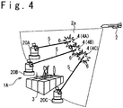
- FIG. 4 is a conceptual diagram showing an example of the electromagnetic pulse protection system 1A according to a second embodiment.
- the electromagnetic pulse protection system 1A in the second embodiment is configured to have a plurality of laser devices, and condense the laser beams 5 generated by the plurality of laser devices on a plurality of light-condensed points 4, respectively. According to such a configuration, since the plasma 6 can be generated in a wide region, the protection object 3 can be protected more surely from the electromagnetic pulse.
- FIG. 5 is a block diagram showing an example of configuration of the electromagnetic pulse protection system 1A in the second embodiment.
- the electromagnetic pulse protection system 1A in the present embodiment includes the threat detecting apparatus 10 and a laser system 30.
- the threat detecting apparatus 10 searches the threat 2.
- the electromagnetic pulse protection system 1A transmits data of the threat 2, e.g. the threat detection data showing the position, the speed and so on, to the laser system 30.
- a laser radar may be used as the threat detecting apparatus 10.
- the laser system 30 sets a plurality of light-condensed points 4 according to the threat detection data received from the threat detecting apparatus 10. Moreover, the laser system 30 is configured to condense the laser beams 5 on the plurality of light-condensed points 4, respectively.
- the laser system 30 includes a laser irradiation control apparatus 31, and a plurality of subsystems 20A to 20C.
- the laser irradiation control apparatus 31 sets the plurality of light-condensed points 4 according to the the threat detection data received from the threat detecting apparatus 10. Moreover, the laser irradiation control apparatus 31 transmits a laser irradiation instruction to instruct each of the subsystems 20A to 20C to irradiate the laser beam 5 so as to condense the laser beam 5 on a corresponding one of the plurality of light-condensed points 4.
- the light-condensed points 4 specified for the subsystems 20A, 20B and 20C are shown by 4A, 4B, and 4C, respectively.
- each of the subsystems 20A, 20B and 20C irradiates the laser beam 5 in response to the laser irradiation instruction transmitted to each of the subsystems so as for the laser beam to be condensed on a corresponding one of the light-condensed points 4A, 4B, and 4C.
- Each of the subsystems 20A to 20C has the same configuration as the laser system 20 in the first embodiment. More specifically, each of the subsystems 20A to 20C has the interface 21, the laser device 22, the driving mechanism 23 and the controller 24.
- the interface 21 receives the laser irradiation instruction from the laser irradiation control apparatus 31 and transfers it to the controller 24.
- the laser device 22 generates the laser beam 5 to be condensed on the light-condensed point 4.
- the laser device 22 is configured as a pulse laser that carries out pulse oscillation.
- the driving mechanism 23 drives the laser device 22 to turn the optical axis of the laser device 22 to a desired direction (that is, the direction to which the laser beam 5 is irradiated).
- the controller 24 controls the laser device 22 and the driving mechanism 23 such that the laser beam 5 is condensed on the light-condensed point 4 in the position instructed by the laser irradiation instruction.
- the controller 24 controls the driving mechanism 23 to turn the optical axis of the laser device 22 to a direction in which the laser beam 5 passes through the light-condensed point 4 and moreover controls the focal length of the laser device 22.
- the operation of the electromagnetic pulse protection system 1A in the second embodiment is the same as that of the electromagnetic pulse protection system 1 in the first embodiment, excluding that the laser beams 5 irradiated from the plurality of laser devices 22 are condensed on the specified light-condensed points 4.
- the search of the threat 2 in the predetermined warning region is carried out by the threat detecting apparatus 10.
- the threat detection data is transmitted to the laser system 30 from the threat detecting apparatus 10.
- the plurality of positions of light-condensed points 4 are set by the laser irradiation control apparatus 31.
- the plurality of light-condensed points 4 may be set to be different from each other in the position. As mentioned above, this is because the region where the plasma 6 is generated is expanded to protect the protection object 3 from the electromagnetic pulse more surely. By expanding the region where the plasma 6 is generated, the electromagnetic pulse can be reflected in a wide region, and it becomes difficult for the electromagnetic pulse to reach the protection object 3 from the threat 2.
- the setting of the positions of light-condensed points 4 is carried out based on the the threat detection data.
- the light-condensed points 4 may be set to the plurality of positions between the threat 2 and the protection object 3, by referring to the threat detection data.
- the prediction position of the threat 2 at a time when the laser beam 5 is to be irradiated may be calculated based on the position, the speed, the direction, the altitude and so on of the threat 2 shown in the threat detection data, and the positions of light-condensed points 4 may be set between the calculated prediction position and the protection object 3.
- the laser irradiation control apparatus 31 transmits the laser irradiation instruction to the subsystems 20A to 20C to instruct each of them to irradiate the laser beam 5 such that the laser beams 5 are condensed on the set light-condensed points 4.
- the laser beams 5 are irradiated from the subsystems 20A to 20C to be condensed on the corresponding light-condensed points 4.
- Each of the subsystems 20A to 20C irradiates the laser beam 5 to be condensed on the light-condensed point 4 specified by the laser irradiation instruction transmitted thereto.
- the optical axis of the laser device 22 is driven by the driving mechanism 23 for the laser beam 5 to pass through the light-condensed point 4.
- the focal length of the laser device 22 is controlled. When the direction control of the optical axis of the laser device 22 and the control of the focal length are completed, the laser device 22 irradiates the laser beam 5.
- the laser beam 5 is condensed on a corresponding one of the light-condensed points 4, and when the electric field strength in the corresponding light-condensed point 4 exceeds breakdown electric field strength in the atmosphere, the plasma 6 is generated in the corresponding light-condensed point 4. Since the plasma 6 has the nature of reflecting the electromagnetic wave having a frequency lower than a plasma frequency. Therefore, the plasma 6 generated by the laser beam 5 functions as an electromagnetic shield to the electromagnetic pulse. Therefore, the protection object 3 can be protected from the electromagnetic pulse 2a generated from the threat 2.
- the position of light-condensed point 4 is determined based on the position of the threat 2.
- the position of light-condensed point 4 may be previously determined irrespective of the position of threat 2.
- the laser beam 5 is condensed on the light-condensed point 4 of previously determined position.
- the electromagnetic pulse protection system 1A in the second embodiment can protect various protection objects from an attack by the strong electromagnetic pulse, like the electromagnetic pulse protection system in the first embodiment.
- the electromagnetic pulse protection system 1 in the present embodiment that uses the plasma for the electromagnetic shield is not necessary to cover the whole protection object 3 with the shield formed of an electric conductive body, and is suitable for protection of the protection object 3 (for example, a radar antenna) having an electric opening and a large-scaled protection object 3.
- the plurality of laser devices 22 i.e. a plurality of subsystems
- a plurality of light-condensed points 4 respectively corresponding to the devices 22 are set.
- the region where the plasma 6 is generated is expanded, to make it possible to protect the protection object 3 from the electromagnetic pulse more surely.
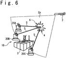
- FIG. 6 is a conceptual diagram showing an example of an electromagnetic pulse protection system 1B according to a third embodiment of the present invention.
- the configuration of the electromagnetic pulse protection system 1B in the third embodiment is identical with that of the electromagnetic pulse protection system 1A in the second embodiment (reference to FIG. 5 ).
- the electromagnetic pulse protection system 1B in the third embodiment is different in that the laser beams 5 generated by the plurality of laser devices are condensed on a single light-condensed point 4.
- FIG. 6 shows that the laser beams 5 generated by the laser devices 22 of the three subsystems 20A to 20C are condensed on a single light-condensed point 4.
- the search of the threat 2 in a predetermined warning region is carried out by the threat detecting apparatus 10, and when the threat 2 is detected through the search, the threat detection data is transmitted to the laser systems 30 from the threat detecting apparatus 10.
- the position of light-condensed point 4 is set by the laser irradiation control apparatus 31.
- the setting of the position of light-condensed point 4 is carried out based on the threat detection data.
- the position of light-condensed point 4 is set based on the position of the threat 2 specified in the threat detection data.
- the light-condensed point 4 may be set to a position between the threat 2 and the protection object 3 by referring to the threat detection data.
- a prediction position of the threat 2 at a time point when the laser beam 5 is to be emitted may be calculated based on the position, the speed, the direction, the altitude and so on of the threat 2 specified in the threat detection data, and the light-condensed point 4 may be set to a position between the calculated prediction position and the protection object 3.
- the laser irradiation control apparatus 31 transmits the laser irradiation instruction to each of the subsystems 20A to 20C to instruct each subsystem to irradiate the laser beam 5 such that the laser beam 5 is condensed on the position of set light-condensed point 4.
- the subsystems 20A to 20C irradiate the laser beams 5 to be condensed on the light-condensed point 4.
- Each of the subsystems 20A to 20C irradiates the laser beam 5 such that the laser beams are condensed on the light-condensed point 4 specified by the laser irradiation instruction.
- the driving mechanism 23 drives each of the subsystems 20A to 20C so as to control the optical axis of the laser device 22 so that the laser beam 5 passes through the light-condensed point 4.
- the focal length of the laser device 22 is controlled. When the direction control of the optical axis of the laser device 22 and the control of the focal length are completed, the laser device 22 irradiates the laser beam 5.
- the laser beam 5 is condensed on the light-condensed point 4, and when the electric field strength in the light-condensed point 4 exceeds breakdown electric field strength in the atmosphere, the plasma 6 is generated in the light-condensed point 4. Since the plasma has the nature of reflecting the electromagnetic wave with a frequency lower than a plasma frequency, the plasma 6 generated by the laser beam 5 functions as the electromagnetic shield to the electromagnetic pulse. Therefore, the protection object 3 can be protected from the electromagnetic pulse 2a generated from the threat 2.
- the position of light-condensed point 4 may be determined based on the position of the threat 2. However, the position of light-condensed point 4 may be previously determined irrespective of the position of the threat 2. In this case, the laser beam 5 is condensed on the light-condensed point 4 of the previously determined position.
- the electromagnetic pulse protection system 1B in the third embodiment can protect various protection objects from the attack by the strong electromagnetic pulse, like the electromagnetic pulse protection systems 1 and 1A in the first and second embodiment.
- the electromagnetic pulse protection system 1B in the present embodiment that uses the plasma for the electromagnetic shield is not necessary to cover the whole protection object 3 by the shield formed of the electrically conductive body, and is suitable for the protection of the protection object 3 (for example, a radar antenna) having an electric opening and the large-scaled protection object 3.
- the electromagnetic pulse protection system 1B in the third embodiment in which the laser beams 5 generated from the plurality of laser devices 22 are condensed on the light-condensed point 4 is suitable for the miniaturization of each laser device 22.
- the electromagnetic pulse protection system 1B in the present embodiment since the laser beams 5 generated from the plurality of laser devices 22 are condensed on the light-condensed point 4, it is possible to make the output of each laser beam 5 small. This means that it is possible to miniaturize each laser device 22.
- each of the subsystems 20A to 20C can be loaded on a moving vehicle (e.g. an automobile and a ship). This contributes to the improvement of operability.
- the electromagnetic pulse protection system 1B in the third embodiment is suitable for the generation of plasma 6 of a large output.
- the electromagnetic pulse protection system 1B in the present embodiment that uses the plurality of laser devices 22 can generate the plasma 6 of a large output by increasing the number of laser devices 22 and/or increasing the output of each laser device 22.
- a plurality of light-condensed points 4 may be set like the second embodiment, and the laser beams 5 generated from the plurality of laser devices 22 may be condensed on at least one light-condensed point 4 (most desirably, respectively, on the plurality of light-condensed points 4).
- the laser beams 5 generated from the plurality of laser devices 22 may be condensed on at least one light-condensed point 4 (most desirably, respectively, on the plurality of light-condensed points 4).
Landscapes
- Engineering & Computer Science (AREA)
- Physics & Mathematics (AREA)
- General Engineering & Computer Science (AREA)
- Plasma & Fusion (AREA)
- Radar, Positioning & Navigation (AREA)
- Remote Sensing (AREA)
- Spectroscopy & Molecular Physics (AREA)
- Electromagnetism (AREA)
- Optics & Photonics (AREA)
- Plasma Technology (AREA)
Abstract
Description
- The present invention relates to an electromagnetic pulse protection method and an electromagnetic pulse protection system.
- When receiving a strong electromagnetic pulse, electronic equipment cannot operate normally, and in some cases, it is destroyed. EMP (electromagnetic pulse) weapon uses such a phenomenon, in which the strong electromagnetic pulse is generated by any method, and is irradiated to a target to hinder the operation of the electronic equipment or to destroy the electronic equipment.
- As a result of the development of the EMP weapon in recent years, it is requested to protect various types of electronic equipment from an attack by such a strong electromagnetic pulse emitted from the EMP weapon. One method for protecting the protection object from the attack by the EMP weapon is a method of covering the whole protection object with a shield formed of an electrically conductive body. However, this method cannot be applied to the protection object such as a radar antenna in which an electric opening is indispensable on the configuration of the apparatus. Also, in a problem of forming the shield, it becomes difficult to prevent the influence of the electromagnetic pulse when a gap is formed in the shield. Also, it is difficult to avoid an adverse influence to the electronic equipment.
- From such a background, it is demanded to provide a technique of protecting various protection objects containing a protection object having an electric opening from the attack by the strong electromagnetic pulse.
- Note that as the technique in conjunction with the present invention,
JP 2007-206588A - [Patent Literature 1]
JP 2007-206588A - Therefore, an object of the present invention is to provide a technique of protecting various protection objects containing a protection object, in which an electric opening is indispensable, from an attack by an electromagnetic pulse.
- The other objects and new features of the present invention could be understood from the disclosure of this Description and the drawings.
- In one aspect of the present invention an electromagnetic pulse protecting method includes: searching a threat which generates an electromagnetic pulse; and generating plasma in a light-condensed point by condensing a laser beam on the light-condensed point in response to detection of the threat.
- In one embodiment, the plasma is generated in each of a plurality of light-condensed points by condensing the laser beam on each of the plurality of light-condensed points. By generating the plasma in each of the plurality of the light-condensed points, the plasma is generated between a protection object to be protected from the electromagnetism pulse, thereby protecting the protection object from the electromagnetism pulse generated from the threat.
- In one embodiment, the laser beams generated by a plurality of laser devices may be condensed on the light-condensed point.
- In another embodiment, the laser beams generated by a plurality of laser devices may be condensed on one of the plurality of light-condensed points.
- It is desirable that the laser beam is a pulse laser beam generated by a pulse laser that carries out pulse oscillation.
- It is desirable that the position of light-condensed point is set based on the position of the threat. In one embodiment, the position of light-condensed point is set between the position of the protection object to be protected from the electromagnetic pulse and the position of the threat.
- In another aspect of the present invention, an electromagnetic pulse protecting system includes: a threat detecting apparatus configured to search a threat that generates an electromagnetic pulse; and a laser system configured to condense a laser beam on a light-condensed point in response to detection of the threat by the threat detecting apparatus, to generate plasma in the light-condensed point.
- In one embodiment, the laser system includes a plurality of laser devices that generates the laser beams. In this case, it is desirable that the laser system is configured such that the laser beams generated from the plurality of laser devices are condensed on the plurality of light-condensed points, respectively, to generate plasma in each of the plurality of light-condensed points.
- In one embodiment, the laser system may be configured such that the laser beams generated by the plurality of laser devices are condensed on the light-condensed point. The laser beams generated from the plurality of laser devices may be condensed on one of the plurality of light-condensed points.
- In one embodiment, the laser system desirably generates the laser beam through pulse oscillation.
- Also, it is desirable that the laser system sets a position of light-condensed point based on the position of the threat. In one embodiment, the position of light-condensed point is set between the protection object to be protected from the electromagnetic pulse and the threat.
- According to the present invention, the various protection objects can be protected from the attack by the electromagnetic pulse.
-
- [
FIG. 1] FIG. 1 is a conceptual diagram showing an example of an electromagnetic pulse protection system according to a first embodiment. - [
FIG. 2] FIG. 2 is a block diagram showing an example of configuration of the electromagnetic pulse protection system in the first embodiment. - [
FIG. 3] FIG. 3 is a flow chart showing an example of operation of the electromagnetic pulse protection system in the first embodiment. - [
FIG. 4] FIG. 4 is a conceptual diagram showing an example of the electromagnetic pulse protection system according to a second embodiment. - [
FIG. 5] FIG. 5 is a block diagram showing an example of configuration of the electromagnetic pulse protection system in the second embodiment - [
FIG. 6] FIG. 6 is a conceptual diagram showing an example of the electromagnetic pulse protection system according to a third embodiment. -
FIG. 1 is a conceptual diagram showing an example of an electromagnetic pulse protection system 1 according to a first embodiment of the present invention. When athreat 2 having attack capability by a strong electromagnetic pulse (EMP) is determined to be approaching aprotection object 3, the electromagnetic pulse protection system 1 in the present embodiment protects theprotection object 3 from theelectromagnetic pulse 2a irradiated from thethreat 2. For example, as thethreat 2, an EMP weapon loaded into a flying object such as an aircraft and a missile is raised. As described below in detail, the electromagnetic pulse protection system 1 in the present embodiment generatesplasma 6 in a light-condensedpoint 4 by condensing alaser beam 5 on the light-condensedpoint 4, and protects theprotection object 3 from theelectromagnetic pulse 2a irradiated from thethreat 2 by using the generatedplasma 6. Since the plasma has the nature of reflecting electromagnetic wave having a lower frequency than a plasma frequency, theprotection object 3 can be protected from theelectromagnetic pulse 2a by generating theplasma 6 in an appropriate position. -
FIG. 2 is a block diagram showing an example of configuration of the electromagnetic pulse protection system 1 in the present embodiment. The electromagnetic pulse protection system 1 in the present embodiment includes athreat detecting apparatus 10 and alaser system 20. Thethreat detecting apparatus 10 is an apparatus that searches thethreat 2, and specifies the position of thethreat 2. When detecting thethreat 2, thethreat detecting apparatus 10 transmits to thelaser system 20, data of thethreat 2, e.g. threat detection data showing the position, the speed, the direction, the altitude and so on. In one embodiment, a laser radar can be used as thethreat detecting apparatus 10. - The
laser system 20 is configured to set the light-condensedpoint 4 based on the threat detection data received from thethreat detecting apparatus 10, and to condense thelaser beam 5 on the set light-condensedpoint 4. In detail, thelaser system 20 includes aninterface 21, thelaser device 22, adriving mechanism 23 and acontroller 24. - The
interface 21 receives the threat detection data from thethreat detecting apparatus 10 and transfers it to thecontroller 24. - The
laser device 22 generates thelaser beam 5. In the present embodiment, thelaser device 22 is configured as a pulse laser that carries out a pulse oscillation. The generatedlaser beam 5 is a pulse laser beam. The reason why the pulse laser is used as thelaser device 22 is in that the generation of the plasma in the light-condensedpoint 4 is easy. As mentioned above, the electromagnetic pulse protection system 1 in the present embodiment adopts the configuration to generate theplasma 6 in the light-condensedpoint 4, and to protect theprotection object 3 from the electromagnetic pulse by theplasma 6. To generate theplasma 6 in the light-condensedpoint 4, it is enough to increase the electric field strength in the light-condensedpoint 4 to an extent stronger than breakdown electric field strength in the atmosphere. The pulse laser is suitable for a high peak output of the laser beam, i.e. a spontaneous increase of the electric field strength. Therefore, it is desirable to use the pulse laser as thelaser device 22 for the generation of plasma. As thelaser device 22, for example, the pulse laser can be used to generate the pulse laser beam having the laser wavelength of 1.06 µm, the pulse duration of 10 ns and the pulse energy of 100 J. Note that if it is possible to generate the plasma, a laser of a continuation wave oscillation type may be used as thelaser device 22. In this case, the laser beam of the continuation wave laser is generated as thelaser beam 5. - The
driving mechanism 23 is a mechanism to drive thelaser device 22 such that the direction of the optical axis of thelaser device 22 turns to a desired direction (that is, the direction to which thelaser beam 5 is emitted). Thedriving mechanism 23 controls the direction of thelaser device 22 such that an elevation angle (an angle between a horizontal plane and an optical axis) and a rotation angle (an angle between a predetermined direction on the horizontal plane and the projection of the optical axis onto the horizontal plane) become equal to command values given from thecontroller 24. - The
controller 24 controls thelaser device 22 and thedriving mechanism 23 such that thelaser beam 5 is condensed on the light-condensedpoint 4 of a desired position. In detail, thecontroller 24 sets the position of light-condensedpoint 4 based on the threat detection data received from thethreat detecting apparatus 10. Moreover, thecontroller 24 controls thedriving mechanism 23 such that thelaser beam 5 is emitted toward the light-condensed point 4 (that is, the optical axis of thelaser device 22 passes through the light-condensed point 4). Also, thecontroller 24 controls the focal length of the laser device 22 (the focal length of the optical system of the laser device 22) so as to condense thelaser beam 5 on the light-condensedpoint 4. -
FIG. 3 is a flow chart showing an example of operation of the electromagnetic pulse protection system 1 in the present embodiment. The search of thethreat 2 in a predetermined warning region (for example, a region that contains the protection object 3) is carried out by the threat detecting apparatus 10 (Step S01). When detecting thethreat 2 through the search, thethreat detecting apparatus 10 transmits data of thethreat 2, e.g. the threat detection data showing the position, the speed and so on of thethreat 2, to thelaser system 20. - Moreover, the position of light-condensed
point 4 is set by thecontroller 24 of the laser system 20 (Step S02). The setting of the position of light-condensedpoint 4 is carried out based on the threat detection data. In the present embodiment, the position of light-condensedpoint 4 is set based on the position of thethreat 2 shown in the the threat detection data. In one embodiment, the light-condensedpoint 4 may be set to a position between thethreat 2 and theprotection object 3 by referring to the threat detection data. Also, in another embodiment, a prediction position of thethreat 2 when thelaser beam 5 be emitted is calculated based on the position, the speed, the direction, the altitude and so on of thethreat 2 shown in the threat detection data. The light-condensedpoint 4 may be set to a position between the calculated prediction position and theprotection object 3. - Moreover, the
laser beam 5 is irradiated to be condensed on the light-condensed point 4 (Step S03). In detail, the direction of the optical axis of thelaser device 22 is controlled by thedriving mechanism 23 such that thelaser beam 5 passes through the light-condensedpoint 4, and the focal length of thelaser device 22 is controlled. When the control direction of the optical axis of thelaser device 22 and the control of the focal length are completed, thelaser device 22 irradiates thelaser beam 5 under the control by thecontroller 24. - When the
laser beam 5 is condensed on the light-condensedpoint 4 so that the electric field strength in the light-condensedpoint 4 exceeds the breakdown electric field strength in the atmosphere, theplasma 6 is generated in the light-condensedpoint 4. Like mentioned above, when the pulse laser beam generated through the pulse oscillation is used as thelaser beam 5, the generation ofplasma 6 becomes easy. Since the plasma has the nature of reflecting electromagnetic wave that has a frequency lower than a plasma frequency, theplasma 6 generated by thelaser beam 5 functions as an electromagnetic shield to the electromagnetic pulse generated by thethreat 2. Therefore, theprotection object 3 can be protected from theelectromagnetic pulse 2a generated by thethreat 2. - The search of the
threat 2 continues to be carried out as long as the electromagnetic pulse protection system 1 operates. The setting of the position of light-condensedpoint 4 and the irradiating of thelaser beam 5 are carried out in response to the detection of threat 2 (for example, every time thethreat 2 is detected). - In the above-mentioned operation, the position of light-condensed
point 4 is determined based on the position of thethreat 2. However, the position of light-condensedpoint 4 may be previously determined irrespective of the position of thethreat 2. In this case, thelaser beam 5 is condensed on the light-condensedpoint 4 of the previously determined position. - One of the advantages of the electromagnetic pulse protection system 1 in the present embodiment is in that various protection objects can be protected from the attack by the electromagnetic pulse. The electromagnetic pulse protection system 1 in the present embodiment that uses the plasma for the electromagnetic shield is not necessary to cover the
whole protection object 3 with a shield material formed of an electrically conductive body. Therefore, the electromagnetic pulse protection system 1 in the present embodiment can be applied even when theprotection object 3 is such as a radar antenna having an electric opening indispensably on the configuration of apparatus. Additionally, the electromagnetic pulse protection system 1 in the present embodiment can protect theprotection object 3 in a low cost even when theprotection object 3 is large-scaled. -
FIG. 4 is a conceptual diagram showing an example of the electromagneticpulse protection system 1A according to a second embodiment. The electromagneticpulse protection system 1A in the second embodiment is configured to have a plurality of laser devices, and condense thelaser beams 5 generated by the plurality of laser devices on a plurality of light-condensedpoints 4, respectively. According to such a configuration, since theplasma 6 can be generated in a wide region, theprotection object 3 can be protected more surely from the electromagnetic pulse. -
FIG. 5 is a block diagram showing an example of configuration of the electromagneticpulse protection system 1A in the second embodiment. The electromagneticpulse protection system 1A in the present embodiment includes thethreat detecting apparatus 10 and alaser system 30. Thethreat detecting apparatus 10 searches thethreat 2. When detecting thethreat 2 through the search, the electromagneticpulse protection system 1A transmits data of thethreat 2, e.g. the threat detection data showing the position, the speed and so on, to thelaser system 30. For example, a laser radar may be used as thethreat detecting apparatus 10. - The
laser system 30 sets a plurality of light-condensedpoints 4 according to the threat detection data received from thethreat detecting apparatus 10. Moreover, thelaser system 30 is configured to condense thelaser beams 5 on the plurality of light-condensedpoints 4, respectively. In detail, thelaser system 30 includes a laserirradiation control apparatus 31, and a plurality ofsubsystems 20A to 20C. - The laser
irradiation control apparatus 31 sets the plurality of light-condensedpoints 4 according to the the threat detection data received from thethreat detecting apparatus 10. Moreover, the laserirradiation control apparatus 31 transmits a laser irradiation instruction to instruct each of thesubsystems 20A to 20C to irradiate thelaser beam 5 so as to condense thelaser beam 5 on a corresponding one of the plurality of light-condensedpoints 4. InFIG. 6 , the light-condensedpoints 4 specified for thesubsystems subsystems laser beam 5 in response to the laser irradiation instruction transmitted to each of the subsystems so as for the laser beam to be condensed on a corresponding one of the light-condensedpoints - Each of the
subsystems 20A to 20C has the same configuration as thelaser system 20 in the first embodiment. More specifically, each of thesubsystems 20A to 20C has theinterface 21, thelaser device 22, thedriving mechanism 23 and thecontroller 24. - The
interface 21 receives the laser irradiation instruction from the laserirradiation control apparatus 31 and transfers it to thecontroller 24. Thelaser device 22 generates thelaser beam 5 to be condensed on the light-condensedpoint 4. Like the first embodiment, thelaser device 22 is configured as a pulse laser that carries out pulse oscillation. Thedriving mechanism 23 drives thelaser device 22 to turn the optical axis of thelaser device 22 to a desired direction (that is, the direction to which thelaser beam 5 is irradiated). Thecontroller 24 controls thelaser device 22 and thedriving mechanism 23 such that thelaser beam 5 is condensed on the light-condensedpoint 4 in the position instructed by the laser irradiation instruction. Thecontroller 24 controls thedriving mechanism 23 to turn the optical axis of thelaser device 22 to a direction in which thelaser beam 5 passes through the light-condensedpoint 4 and moreover controls the focal length of thelaser device 22. - The operation of the electromagnetic
pulse protection system 1A in the second embodiment is the same as that of the electromagnetic pulse protection system 1 in the first embodiment, excluding that thelaser beams 5 irradiated from the plurality oflaser devices 22 are condensed on the specified light-condensedpoints 4. - More specifically, the search of the
threat 2 in the predetermined warning region (for example, the region that contains the protection object 3) is carried out by thethreat detecting apparatus 10. When thethreat 2 is detected through the search, the threat detection data is transmitted to thelaser system 30 from thethreat detecting apparatus 10. - Moreover, the plurality of positions of light-condensed
points 4 are set by the laserirradiation control apparatus 31. The plurality of light-condensedpoints 4 may be set to be different from each other in the position. As mentioned above, this is because the region where theplasma 6 is generated is expanded to protect theprotection object 3 from the electromagnetic pulse more surely. By expanding the region where theplasma 6 is generated, the electromagnetic pulse can be reflected in a wide region, and it becomes difficult for the electromagnetic pulse to reach theprotection object 3 from thethreat 2. - In the present embodiment, the setting of the positions of light-condensed
points 4 is carried out based on the the threat detection data. In one embodiment, the light-condensedpoints 4 may be set to the plurality of positions between thethreat 2 and theprotection object 3, by referring to the threat detection data. Or, in another embodiment, the prediction position of thethreat 2 at a time when thelaser beam 5 is to be irradiated may be calculated based on the position, the speed, the direction, the altitude and so on of thethreat 2 shown in the threat detection data, and the positions of light-condensedpoints 4 may be set between the calculated prediction position and theprotection object 3. The laserirradiation control apparatus 31 transmits the laser irradiation instruction to thesubsystems 20A to 20C to instruct each of them to irradiate thelaser beam 5 such that thelaser beams 5 are condensed on the set light-condensedpoints 4. - Moreover, the
laser beams 5 are irradiated from thesubsystems 20A to 20C to be condensed on the corresponding light-condensedpoints 4. Each of thesubsystems 20A to 20C irradiates thelaser beam 5 to be condensed on the light-condensedpoint 4 specified by the laser irradiation instruction transmitted thereto. In each of thesubsystems 20A to 20C, the optical axis of thelaser device 22 is driven by thedriving mechanism 23 for thelaser beam 5 to pass through the light-condensedpoint 4. Moreover, the focal length of thelaser device 22 is controlled. When the direction control of the optical axis of thelaser device 22 and the control of the focal length are completed, thelaser device 22 irradiates thelaser beam 5. - The
laser beam 5 is condensed on a corresponding one of the light-condensedpoints 4, and when the electric field strength in the corresponding light-condensedpoint 4 exceeds breakdown electric field strength in the atmosphere, theplasma 6 is generated in the corresponding light-condensedpoint 4. Since theplasma 6 has the nature of reflecting the electromagnetic wave having a frequency lower than a plasma frequency. Therefore, theplasma 6 generated by thelaser beam 5 functions as an electromagnetic shield to the electromagnetic pulse. Therefore, theprotection object 3 can be protected from theelectromagnetic pulse 2a generated from thethreat 2. - Note that in the above-mentioned operation, the position of light-condensed
point 4 is determined based on the position of thethreat 2. However, the position of light-condensedpoint 4 may be previously determined irrespective of the position ofthreat 2. In this case, thelaser beam 5 is condensed on the light-condensedpoint 4 of previously determined position. - The electromagnetic
pulse protection system 1A in the second embodiment can protect various protection objects from an attack by the strong electromagnetic pulse, like the electromagnetic pulse protection system in the first embodiment. The electromagnetic pulse protection system 1 in the present embodiment that uses the plasma for the electromagnetic shield is not necessary to cover thewhole protection object 3 with the shield formed of an electric conductive body, and is suitable for protection of the protection object 3 (for example, a radar antenna) having an electric opening and a large-scaledprotection object 3. - Additionally, in the second embodiment, the plurality of laser devices 22 (i.e. a plurality of subsystems) are provided, and a plurality of light-condensed
points 4 respectively corresponding to thedevices 22 are set. Thus, the region where theplasma 6 is generated is expanded, to make it possible to protect theprotection object 3 from the electromagnetic pulse more surely. -
FIG. 6 is a conceptual diagram showing an example of an electromagneticpulse protection system 1B according to a third embodiment of the present invention. The configuration of the electromagneticpulse protection system 1B in the third embodiment is identical with that of the electromagneticpulse protection system 1A in the second embodiment (reference toFIG. 5 ). However, the electromagneticpulse protection system 1B in the third embodiment is different in that thelaser beams 5 generated by the plurality of laser devices are condensed on a single light-condensedpoint 4.FIG. 6 shows that thelaser beams 5 generated by thelaser devices 22 of the threesubsystems 20A to 20C are condensed on a single light-condensedpoint 4. - More specifically, the search of the
threat 2 in a predetermined warning region (for example, region which contains the protection object 3) is carried out by thethreat detecting apparatus 10, and when thethreat 2 is detected through the search, the threat detection data is transmitted to thelaser systems 30 from thethreat detecting apparatus 10. - Moreover, the position of light-condensed
point 4 is set by the laserirradiation control apparatus 31. The setting of the position of light-condensedpoint 4 is carried out based on the threat detection data. In the present embodiment, the position of light-condensedpoint 4 is set based on the position of thethreat 2 specified in the threat detection data. In one embodiment, the light-condensedpoint 4 may be set to a position between thethreat 2 and theprotection object 3 by referring to the threat detection data. In another embodiment, a prediction position of thethreat 2 at a time point when thelaser beam 5 is to be emitted may be calculated based on the position, the speed, the direction, the altitude and so on of thethreat 2 specified in the threat detection data, and the light-condensedpoint 4 may be set to a position between the calculated prediction position and theprotection object 3. The laserirradiation control apparatus 31 transmits the laser irradiation instruction to each of thesubsystems 20A to 20C to instruct each subsystem to irradiate thelaser beam 5 such that thelaser beam 5 is condensed on the position of set light-condensedpoint 4. - Moreover, the
subsystems 20A to 20C irradiate thelaser beams 5 to be condensed on the light-condensedpoint 4. Each of thesubsystems 20A to 20C irradiates thelaser beam 5 such that the laser beams are condensed on the light-condensedpoint 4 specified by the laser irradiation instruction. Thedriving mechanism 23 drives each of thesubsystems 20A to 20C so as to control the optical axis of thelaser device 22 so that thelaser beam 5 passes through the light-condensedpoint 4. Moreover, the focal length of thelaser device 22 is controlled. When the direction control of the optical axis of thelaser device 22 and the control of the focal length are completed, thelaser device 22 irradiates thelaser beam 5. - The
laser beam 5 is condensed on the light-condensedpoint 4, and when the electric field strength in the light-condensedpoint 4 exceeds breakdown electric field strength in the atmosphere, theplasma 6 is generated in the light-condensedpoint 4. Since the plasma has the nature of reflecting the electromagnetic wave with a frequency lower than a plasma frequency, theplasma 6 generated by thelaser beam 5 functions as the electromagnetic shield to the electromagnetic pulse. Therefore, theprotection object 3 can be protected from theelectromagnetic pulse 2a generated from thethreat 2. - Note that in the above-mentioned operation, the position of light-condensed
point 4 may be determined based on the position of thethreat 2. However, the position of light-condensedpoint 4 may be previously determined irrespective of the position of thethreat 2. In this case, thelaser beam 5 is condensed on the light-condensedpoint 4 of the previously determined position. - The electromagnetic
pulse protection system 1B in the third embodiment can protect various protection objects from the attack by the strong electromagnetic pulse, like the electromagneticpulse protection systems 1 and 1A in the first and second embodiment. The electromagneticpulse protection system 1B in the present embodiment that uses the plasma for the electromagnetic shield is not necessary to cover thewhole protection object 3 by the shield formed of the electrically conductive body, and is suitable for the protection of the protection object 3 (for example, a radar antenna) having an electric opening and the large-scaledprotection object 3. - In addition, the electromagnetic
pulse protection system 1B in the third embodiment in which thelaser beams 5 generated from the plurality oflaser devices 22 are condensed on the light-condensedpoint 4 is suitable for the miniaturization of eachlaser device 22. In the electromagneticpulse protection system 1B in the present embodiment, since thelaser beams 5 generated from the plurality oflaser devices 22 are condensed on the light-condensedpoint 4, it is possible to make the output of eachlaser beam 5 small. This means that it is possible to miniaturize eachlaser device 22. By miniaturizing eachlaser device 22, each of thesubsystems 20A to 20C can be loaded on a moving vehicle (e.g. an automobile and a ship). This contributes to the improvement of operability. - Viewing from the different viewpoint, the electromagnetic
pulse protection system 1B in the third embodiment is suitable for the generation ofplasma 6 of a large output. The electromagneticpulse protection system 1B in the present embodiment that uses the plurality oflaser devices 22 can generate theplasma 6 of a large output by increasing the number oflaser devices 22 and/or increasing the output of eachlaser device 22. - Note that a plurality of light-condensed
points 4 may be set like the second embodiment, and thelaser beams 5 generated from the plurality oflaser devices 22 may be condensed on at least one light-condensed point 4 (most desirably, respectively, on the plurality of light-condensed points 4). Thus, while generating theplasma 6 in a wide region, it is possible to reduce the output of each laser device 22 (or, to generate theplasma 6 of a large output). Such a technique can be adopted when the number oflaser devices 22 is more than the number of light-condensedpoints 4. - As mentioned above, the embodiments of the present invention have been variously described. However, the present invention should not be interpreted as being limited to the above-mentioned embodiments. It would be apparent to the skilled person that the present invention can be implemented various changes or modifications.
Claims (15)
- An electromagnetic pulse protecting method comprising:searching a threat which generates an electromagnetic pulse; andgenerating plasma in a light-condensed point by condensing a laser beam on the light-condensed point in response to detection of the threat.
- The electromagnetic pulse protecting method according to claim 1, wherein the generating comprises:generating the plasma in each of a plurality of the light-condensed points by condensing the laser beam on each of the plurality of light-condensed points.
- The electromagnetic pulse protecting method according to claim 2, wherein the generating the plasma in each of the plurality of light-condensed points comprises:generating the plasma between a protection object to be protected from the electromagnetism pulse and the threat to shield the protection object from the electromagnetism pulse generated from the threat.
- The electromagnetic pulse protecting method according to claim 1, wherein the generating comprises:condensing a plurality of the laser beams generated from a plurality of laser devices on the light-condensed point.
- The electromagnetic pulse protection method according to claim 2, wherein the condensing comprises:condensing a plurality of the laser beams generated from plural ones of a plurality of laser devices on one of a plurality of the light-condensed points.
- The electromagnetic pulse protection method according to any one of claims 1 to 5, further comprising:generating the laser beam from a pulse laser that carries out pulse oscillation.
- The electromagnetic pulse protecting method according to claim 1, further comprising:determining the position of light-condensed point based on the position of threat.
- The electromagnetic pulse protecting method according to claim 7, wherein the determining comprises:setting a position of light-condensed point between the position of the protection object to be protected from the electromagnetism pulse and the position of the threat.
- An electromagnetic pulse protecting system comprising:a threat detecting apparatus configured to search a threat that generates an electromagnetic pulse; anda laser system configured to condense a laser beam on a light-condensed point in response to detection of the threat by the threat detecting apparatus, to generate plasma in the light-condensed point.
- The electromagnetic pulse protecting system according to claim 9, wherein the laser system comprises:a plurality of laser devices, each of which generates the laser beam,wherein the laser system condenses the laser beams generated from the plurality of laser devices on one a plurality of the light-condensed points, so as to generate the plasma in each of the plurality of light-condensed points.
- The electromagnetic pulse protecting system according to claim 9, wherein the laser system comprises:a plurality of laser devices, each of which generates the laser beam, andwherein the laser system condenses the laser beams generated from the plurality of laser devices on the light-condensed point.
- The electromagnetic pulse protection system according to claim 10, wherein the laser beams generated from plural ones of the plurality of laser devices are condensed on one of the plurality of light-condensed points.
- The electromagnetic pulse protecting system according to any one of claims 9 to 12, wherein the laser system generates the laser beam by carrying out pulse oscillation.
- The electromagnetic pulse protecting system according to claim 9, wherein the laser system sets the position of light-condensed point based on a position of the threat.
- The electromagnetic pulse protecting system according to claim 14, wherein the position of light-condensed point is set to a position between the protection object to be protected from the electromagnetism pulse and the position of the threat.
Applications Claiming Priority (2)
| Application Number | Priority Date | Filing Date | Title |
|---|---|---|---|
| JP2015131626A JP6376408B2 (en) | 2015-06-30 | 2015-06-30 | Electromagnetic pulse protection method and electromagnetic pulse protection system |
| PCT/JP2016/062002 WO2017002428A1 (en) | 2015-06-30 | 2016-04-14 | Electromagnetic pulse protection method and electromagnetic pulse protection system |
Publications (3)
| Publication Number | Publication Date |
|---|---|
| EP3267142A1 true EP3267142A1 (en) | 2018-01-10 |
| EP3267142A4 EP3267142A4 (en) | 2018-04-11 |
| EP3267142B1 EP3267142B1 (en) | 2022-04-06 |
Family
ID=57609485
Family Applications (1)
| Application Number | Title | Priority Date | Filing Date |
|---|---|---|---|
| EP16817538.8A Active EP3267142B1 (en) | 2015-06-30 | 2016-04-14 | Electromagnetic pulse protection method and electromagnetic pulse protection system |
Country Status (4)
| Country | Link |
|---|---|
| US (1) | US10342111B2 (en) |
| EP (1) | EP3267142B1 (en) |
| JP (1) | JP6376408B2 (en) |
| WO (1) | WO2017002428A1 (en) |
Families Citing this family (10)
| Publication number | Priority date | Publication date | Assignee | Title |
|---|---|---|---|---|
| DE102014014117A1 (en) * | 2014-09-24 | 2016-03-24 | Diehl Bgt Defence Gmbh & Co. Kg | A defense device for controlling an unmanned aerial vehicle, a protective device for controlling an unmanned aerial vehicle, and a method for operating a protective device |
| JP6376407B2 (en) | 2015-06-30 | 2018-08-22 | 三菱重工業株式会社 | Electromagnetic pulse irradiation method and electromagnetic pulse irradiation system |
| US20170127507A1 (en) * | 2015-11-04 | 2017-05-04 | The Boeing Company | Defense mechanism against directed-energy systems based on laser induced atmospheric optical breakdown |
| JP6774305B2 (en) * | 2016-11-08 | 2020-10-21 | 三菱重工業株式会社 | Underwater object destruction system and underwater object destruction method |
| NL2025053B1 (en) * | 2020-03-05 | 2021-10-14 | Aptinfo B V | Plasma burst application system and method |
| CN111397444A (en) * | 2020-03-18 | 2020-07-10 | 华中科技大学鄂州工业技术研究院 | Laser directional energy cluster transmitting system and method |
| JP7703345B2 (en) * | 2021-03-24 | 2025-07-07 | 株式会社東芝 | Wireless device and control method |
| US11782080B2 (en) | 2021-07-30 | 2023-10-10 | JaXon Engineering and Maintenance LLC | Remotely controlled, automated shielding effectiveness test system for high-altitude electromagnetic pulse detection |
| US12399263B2 (en) * | 2021-11-15 | 2025-08-26 | The United States Of America, As Represented By The Secretary Of The Navy | Target jamming |
| US12601569B2 (en) | 2024-03-19 | 2026-04-14 | Jonathan Schroeder | Systems for projecting high voltage electrical discharges in air |
Family Cites Families (23)
| Publication number | Priority date | Publication date | Assignee | Title |
|---|---|---|---|---|
| JPH0772680B2 (en) * | 1992-02-05 | 1995-08-02 | 防衛庁技術研究本部長 | Proximity protection device |
| US5747720A (en) | 1995-06-01 | 1998-05-05 | Trw Inc. | Tactical laser weapon system for handling munitions |
| JPH1059297A (en) * | 1996-08-21 | 1998-03-03 | Mitsubishi Heavy Ind Ltd | Air intake shielding device using laser |
| JP3903608B2 (en) | 1998-08-25 | 2007-04-11 | 三菱電機株式会社 | Missile jammer |
| TWI231405B (en) | 1999-12-22 | 2005-04-21 | Asml Netherlands Bv | Lithographic projection apparatus, position detection device, and method of manufacturing a device using a lithographic projection apparatus |
| JP3650811B2 (en) | 2002-02-13 | 2005-05-25 | 株式会社トプコン | Aerial visible image forming device |
| US6843178B2 (en) * | 2002-08-22 | 2005-01-18 | Lockheed Martin Corporation | Electromagnetic pulse transmitting system and method |
| US7255062B1 (en) * | 2004-05-07 | 2007-08-14 | Higman Kumiko I | Pseudo surface microwave produced plasma shielding system |
| JP2006226608A (en) * | 2005-02-17 | 2006-08-31 | Toshiba Corp | Shooting control device |
| FR2887327B1 (en) * | 2005-06-17 | 2007-08-24 | Thales Sa | METHOD FOR THE PROTECTION OF ANTIMISSIL VEHICLES AND DEVICE FOR IMPLEMENTING THE SAME |
| DE102005034613B3 (en) * | 2005-07-18 | 2007-03-29 | Deutsches Zentrum für Luft- und Raumfahrt e.V. | Anti-missile defense device, anti-missile defense method and use of a laser device |
| US20070051233A1 (en) | 2005-09-06 | 2007-03-08 | Duge Robert T | Radiant electromagnetic energy management |
| JP4773222B2 (en) | 2006-02-06 | 2011-09-14 | 独立行政法人産業技術総合研究所 | Aerial visible image forming apparatus and aerial visible image forming method |
| JP5358060B2 (en) | 2007-02-20 | 2013-12-04 | ギガフォトン株式会社 | Extreme ultraviolet light source device |
| DE102007049436B4 (en) | 2007-10-16 | 2009-07-09 | Lfk-Lenkflugkörpersysteme Gmbh | Fiber laser array high beam power |
| ATE547686T1 (en) | 2008-08-15 | 2012-03-15 | Saab Ab | LAUNCHABLE UNIT |
| US8283643B2 (en) | 2008-11-24 | 2012-10-09 | Cymer, Inc. | Systems and methods for drive laser beam delivery in an EUV light source |
| KR101200943B1 (en) | 2010-04-06 | 2012-11-13 | 한국과학기술원 | High-energy laser system intercepting a target and method thereof |
| JP5832115B2 (en) | 2011-03-30 | 2015-12-16 | 三菱重工業株式会社 | Directional energy system |
| US20160097616A1 (en) | 2011-11-25 | 2016-04-07 | Dr. Adam Mark Weigold | Laser Guided and Laser Powered Energy Discharge Device |
| US8981261B1 (en) * | 2012-05-30 | 2015-03-17 | The Boeing Company | Method and system for shockwave attenuation via electromagnetic arc |
| JP5986476B2 (en) | 2012-10-16 | 2016-09-06 | 浜松ホトニクス株式会社 | Laser fusion apparatus and fusion generation method |
| JP6376407B2 (en) * | 2015-06-30 | 2018-08-22 | 三菱重工業株式会社 | Electromagnetic pulse irradiation method and electromagnetic pulse irradiation system |
-
2015
- 2015-06-30 JP JP2015131626A patent/JP6376408B2/en active Active
-
2016
- 2016-04-14 US US15/562,642 patent/US10342111B2/en active Active
- 2016-04-14 WO PCT/JP2016/062002 patent/WO2017002428A1/en not_active Ceased
- 2016-04-14 EP EP16817538.8A patent/EP3267142B1/en active Active
Also Published As
| Publication number | Publication date |
|---|---|
| JP2017015312A (en) | 2017-01-19 |
| WO2017002428A1 (en) | 2017-01-05 |
| JP6376408B2 (en) | 2018-08-22 |
| US10342111B2 (en) | 2019-07-02 |
| EP3267142B1 (en) | 2022-04-06 |
| EP3267142A4 (en) | 2018-04-11 |
| US20180092195A1 (en) | 2018-03-29 |
Similar Documents
| Publication | Publication Date | Title |
|---|---|---|
| US10342111B2 (en) | Electromagnetic pulse protection method and electromagnetic pulse protection system | |
| EP3276298B1 (en) | Method of irradiatiing electromagnetic pulse and electromagnetic pulse irradiation system | |
| EP2630434B1 (en) | Countermeasure system | |
| EP2527865B1 (en) | System, device and method of protecting aircrafts against incoming missiles and threats | |
| US8981261B1 (en) | Method and system for shockwave attenuation via electromagnetic arc | |
| US7930967B2 (en) | Method for antimissile protection of vehicles and implementing device | |
| US12372335B2 (en) | Plasma burst application system and method | |
| US11181347B2 (en) | Underwater object destruction system and underwater object destruction method | |
| AU2012228172B2 (en) | Integrated system for combating improvised explosive devices | |
| EP4400801A1 (en) | Threat countermeasure system and storage medium | |
| CA2632220C (en) | Method of agile reduction of radar cross section using electromagnetic channelization | |
| KR102831508B1 (en) | Physical countermeasure defense system based on hard-kill interception system and target shooting method thereof | |
| RU2859071C1 (en) | Method for combating unmanned aerial vehicles and system for its implementation | |
| RU2700206C1 (en) | Method of two-factor functional suppression of unmanned aerial vehicle | |
| Valouch | Electromagnetic Devices for Stopping Vehicles | |
| Kwon et al. | A Survey of Military Anti-Satellite Weapon Systems and Corresponding Countermeasures | |
| JP2650793B2 (en) | Guided flying object | |
| CN119291721A (en) | A broadband navigation deception, suppression and jamming system based on optical microwave technology | |
| DENIAL | Project NUSRET: A Comprehensive Technical Framework for Persistent Electromagnetic Volumetric Denial and the Invisible Air Minefield | |
| Analysers | Why drone Point Defence Solutions are “pointless” for Strategic Asset Protection | |
| Chow et al. | Following the original publication of this document, subsequent discussions with Mr. James Pep-pler at the Mitre Corporation were helpful in clarifying technical issues on countermeasures. | |
| IL153781A (en) | Laser directional infrared countermeasures (dircm) system for protecting aircraft with a large thermal signature against missiles |
Legal Events
| Date | Code | Title | Description |
|---|---|---|---|
| STAA | Information on the status of an ep patent application or granted ep patent |
Free format text: STATUS: THE INTERNATIONAL PUBLICATION HAS BEEN MADE |
|
| PUAI | Public reference made under article 153(3) epc to a published international application that has entered the european phase |
Free format text: ORIGINAL CODE: 0009012 |
|
| STAA | Information on the status of an ep patent application or granted ep patent |
Free format text: STATUS: REQUEST FOR EXAMINATION WAS MADE |
|
| 17P | Request for examination filed |
Effective date: 20171005 |
|
| AK | Designated contracting states |
Kind code of ref document: A1 Designated state(s): AL AT BE BG CH CY CZ DE DK EE ES FI FR GB GR HR HU IE IS IT LI LT LU LV MC MK MT NL NO PL PT RO RS SE SI SK SM TR |
|
| AX | Request for extension of the european patent |
Extension state: BA ME |
|
| A4 | Supplementary search report drawn up and despatched |
Effective date: 20180314 |
|
| RIC1 | Information provided on ipc code assigned before grant |
Ipc: F41H 13/00 20060101AFI20180308BHEP Ipc: F41H 11/00 20060101ALI20180308BHEP Ipc: H05H 1/24 20060101ALI20180308BHEP |
|
| DAV | Request for validation of the european patent (deleted) | ||
| DAX | Request for extension of the european patent (deleted) | ||
| GRAP | Despatch of communication of intention to grant a patent |
Free format text: ORIGINAL CODE: EPIDOSNIGR1 |
|
| STAA | Information on the status of an ep patent application or granted ep patent |
Free format text: STATUS: GRANT OF PATENT IS INTENDED |
|
| INTG | Intention to grant announced |
Effective date: 20211019 |
|
| GRAS | Grant fee paid |
Free format text: ORIGINAL CODE: EPIDOSNIGR3 |
|
| GRAA | (expected) grant |
Free format text: ORIGINAL CODE: 0009210 |
|
| STAA | Information on the status of an ep patent application or granted ep patent |
Free format text: STATUS: THE PATENT HAS BEEN GRANTED |
|
| AK | Designated contracting states |
Kind code of ref document: B1 Designated state(s): AL AT BE BG CH CY CZ DE DK EE ES FI FR GB GR HR HU IE IS IT LI LT LU LV MC MK MT NL NO PL PT RO RS SE SI SK SM TR |
|
| REG | Reference to a national code |
Ref country code: GB Ref legal event code: FG4D |
|
| REG | Reference to a national code |
Ref country code: CH Ref legal event code: EP |
|
| REG | Reference to a national code |
Ref country code: AT Ref legal event code: REF Ref document number: 1481722 Country of ref document: AT Kind code of ref document: T Effective date: 20220415 |
|
| REG | Reference to a national code |
Ref country code: IE Ref legal event code: FG4D |
|
| REG | Reference to a national code |
Ref country code: DE Ref legal event code: R096 Ref document number: 602016070855 Country of ref document: DE |
|
| REG | Reference to a national code |
Ref country code: LT Ref legal event code: MG9D |
|
| REG | Reference to a national code |
Ref country code: NL Ref legal event code: MP Effective date: 20220406 |
|
| REG | Reference to a national code |
Ref country code: AT Ref legal event code: MK05 Ref document number: 1481722 Country of ref document: AT Kind code of ref document: T Effective date: 20220406 |
|
| PG25 | Lapsed in a contracting state [announced via postgrant information from national office to epo] |
Ref country code: NL Free format text: LAPSE BECAUSE OF FAILURE TO SUBMIT A TRANSLATION OF THE DESCRIPTION OR TO PAY THE FEE WITHIN THE PRESCRIBED TIME-LIMIT Effective date: 20220406 |
|
| PG25 | Lapsed in a contracting state [announced via postgrant information from national office to epo] |
Ref country code: SE Free format text: LAPSE BECAUSE OF FAILURE TO SUBMIT A TRANSLATION OF THE DESCRIPTION OR TO PAY THE FEE WITHIN THE PRESCRIBED TIME-LIMIT Effective date: 20220406 Ref country code: PT Free format text: LAPSE BECAUSE OF FAILURE TO SUBMIT A TRANSLATION OF THE DESCRIPTION OR TO PAY THE FEE WITHIN THE PRESCRIBED TIME-LIMIT Effective date: 20220808 Ref country code: NO Free format text: LAPSE BECAUSE OF FAILURE TO SUBMIT A TRANSLATION OF THE DESCRIPTION OR TO PAY THE FEE WITHIN THE PRESCRIBED TIME-LIMIT Effective date: 20220706 Ref country code: LT Free format text: LAPSE BECAUSE OF FAILURE TO SUBMIT A TRANSLATION OF THE DESCRIPTION OR TO PAY THE FEE WITHIN THE PRESCRIBED TIME-LIMIT Effective date: 20220406 Ref country code: HR Free format text: LAPSE BECAUSE OF FAILURE TO SUBMIT A TRANSLATION OF THE DESCRIPTION OR TO PAY THE FEE WITHIN THE PRESCRIBED TIME-LIMIT Effective date: 20220406 Ref country code: GR Free format text: LAPSE BECAUSE OF FAILURE TO SUBMIT A TRANSLATION OF THE DESCRIPTION OR TO PAY THE FEE WITHIN THE PRESCRIBED TIME-LIMIT Effective date: 20220707 Ref country code: FI Free format text: LAPSE BECAUSE OF FAILURE TO SUBMIT A TRANSLATION OF THE DESCRIPTION OR TO PAY THE FEE WITHIN THE PRESCRIBED TIME-LIMIT Effective date: 20220406 Ref country code: ES Free format text: LAPSE BECAUSE OF FAILURE TO SUBMIT A TRANSLATION OF THE DESCRIPTION OR TO PAY THE FEE WITHIN THE PRESCRIBED TIME-LIMIT Effective date: 20220406 Ref country code: BG Free format text: LAPSE BECAUSE OF FAILURE TO SUBMIT A TRANSLATION OF THE DESCRIPTION OR TO PAY THE FEE WITHIN THE PRESCRIBED TIME-LIMIT Effective date: 20220706 Ref country code: AT Free format text: LAPSE BECAUSE OF FAILURE TO SUBMIT A TRANSLATION OF THE DESCRIPTION OR TO PAY THE FEE WITHIN THE PRESCRIBED TIME-LIMIT Effective date: 20220406 |
|
| PG25 | Lapsed in a contracting state [announced via postgrant information from national office to epo] |
Ref country code: RS Free format text: LAPSE BECAUSE OF FAILURE TO SUBMIT A TRANSLATION OF THE DESCRIPTION OR TO PAY THE FEE WITHIN THE PRESCRIBED TIME-LIMIT Effective date: 20220406 Ref country code: PL Free format text: LAPSE BECAUSE OF FAILURE TO SUBMIT A TRANSLATION OF THE DESCRIPTION OR TO PAY THE FEE WITHIN THE PRESCRIBED TIME-LIMIT Effective date: 20220406 Ref country code: LV Free format text: LAPSE BECAUSE OF FAILURE TO SUBMIT A TRANSLATION OF THE DESCRIPTION OR TO PAY THE FEE WITHIN THE PRESCRIBED TIME-LIMIT Effective date: 20220406 Ref country code: IS Free format text: LAPSE BECAUSE OF FAILURE TO SUBMIT A TRANSLATION OF THE DESCRIPTION OR TO PAY THE FEE WITHIN THE PRESCRIBED TIME-LIMIT Effective date: 20220806 |
|
| REG | Reference to a national code |
Ref country code: CH Ref legal event code: PL |
|
| REG | Reference to a national code |
Ref country code: BE Ref legal event code: MM Effective date: 20220430 |
|
| REG | Reference to a national code |
Ref country code: DE Ref legal event code: R097 Ref document number: 602016070855 Country of ref document: DE |
|
| PG25 | Lapsed in a contracting state [announced via postgrant information from national office to epo] |
Ref country code: SM Free format text: LAPSE BECAUSE OF FAILURE TO SUBMIT A TRANSLATION OF THE DESCRIPTION OR TO PAY THE FEE WITHIN THE PRESCRIBED TIME-LIMIT Effective date: 20220406 Ref country code: SK Free format text: LAPSE BECAUSE OF FAILURE TO SUBMIT A TRANSLATION OF THE DESCRIPTION OR TO PAY THE FEE WITHIN THE PRESCRIBED TIME-LIMIT Effective date: 20220406 Ref country code: RO Free format text: LAPSE BECAUSE OF FAILURE TO SUBMIT A TRANSLATION OF THE DESCRIPTION OR TO PAY THE FEE WITHIN THE PRESCRIBED TIME-LIMIT Effective date: 20220406 Ref country code: MC Free format text: LAPSE BECAUSE OF FAILURE TO SUBMIT A TRANSLATION OF THE DESCRIPTION OR TO PAY THE FEE WITHIN THE PRESCRIBED TIME-LIMIT Effective date: 20220406 Ref country code: LU Free format text: LAPSE BECAUSE OF NON-PAYMENT OF DUE FEES Effective date: 20220414 Ref country code: LI Free format text: LAPSE BECAUSE OF NON-PAYMENT OF DUE FEES Effective date: 20220430 Ref country code: EE Free format text: LAPSE BECAUSE OF FAILURE TO SUBMIT A TRANSLATION OF THE DESCRIPTION OR TO PAY THE FEE WITHIN THE PRESCRIBED TIME-LIMIT Effective date: 20220406 Ref country code: DK Free format text: LAPSE BECAUSE OF FAILURE TO SUBMIT A TRANSLATION OF THE DESCRIPTION OR TO PAY THE FEE WITHIN THE PRESCRIBED TIME-LIMIT Effective date: 20220406 Ref country code: CZ Free format text: LAPSE BECAUSE OF FAILURE TO SUBMIT A TRANSLATION OF THE DESCRIPTION OR TO PAY THE FEE WITHIN THE PRESCRIBED TIME-LIMIT Effective date: 20220406 Ref country code: CH Free format text: LAPSE BECAUSE OF NON-PAYMENT OF DUE FEES Effective date: 20220430 |
|
| PLBE | No opposition filed within time limit |
Free format text: ORIGINAL CODE: 0009261 |
|
| STAA | Information on the status of an ep patent application or granted ep patent |
Free format text: STATUS: NO OPPOSITION FILED WITHIN TIME LIMIT |
|
| PG25 | Lapsed in a contracting state [announced via postgrant information from national office to epo] |
Ref country code: BE Free format text: LAPSE BECAUSE OF NON-PAYMENT OF DUE FEES Effective date: 20220430 |
|
| 26N | No opposition filed |
Effective date: 20230110 |
|
| PG25 | Lapsed in a contracting state [announced via postgrant information from national office to epo] |
Ref country code: AL Free format text: LAPSE BECAUSE OF FAILURE TO SUBMIT A TRANSLATION OF THE DESCRIPTION OR TO PAY THE FEE WITHIN THE PRESCRIBED TIME-LIMIT Effective date: 20220406 |
|
| PG25 | Lapsed in a contracting state [announced via postgrant information from national office to epo] |
Ref country code: IE Free format text: LAPSE BECAUSE OF NON-PAYMENT OF DUE FEES Effective date: 20220414 |
|
| PG25 | Lapsed in a contracting state [announced via postgrant information from national office to epo] |
Ref country code: SI Free format text: LAPSE BECAUSE OF FAILURE TO SUBMIT A TRANSLATION OF THE DESCRIPTION OR TO PAY THE FEE WITHIN THE PRESCRIBED TIME-LIMIT Effective date: 20220406 |
|
| PG25 | Lapsed in a contracting state [announced via postgrant information from national office to epo] |
Ref country code: IT Free format text: LAPSE BECAUSE OF FAILURE TO SUBMIT A TRANSLATION OF THE DESCRIPTION OR TO PAY THE FEE WITHIN THE PRESCRIBED TIME-LIMIT Effective date: 20220406 |
|
| PG25 | Lapsed in a contracting state [announced via postgrant information from national office to epo] |
Ref country code: HU Free format text: LAPSE BECAUSE OF FAILURE TO SUBMIT A TRANSLATION OF THE DESCRIPTION OR TO PAY THE FEE WITHIN THE PRESCRIBED TIME-LIMIT; INVALID AB INITIO Effective date: 20160414 |
|
| PG25 | Lapsed in a contracting state [announced via postgrant information from national office to epo] |
Ref country code: MK Free format text: LAPSE BECAUSE OF FAILURE TO SUBMIT A TRANSLATION OF THE DESCRIPTION OR TO PAY THE FEE WITHIN THE PRESCRIBED TIME-LIMIT Effective date: 20220406 Ref country code: CY Free format text: LAPSE BECAUSE OF FAILURE TO SUBMIT A TRANSLATION OF THE DESCRIPTION OR TO PAY THE FEE WITHIN THE PRESCRIBED TIME-LIMIT Effective date: 20220406 |
|
| PG25 | Lapsed in a contracting state [announced via postgrant information from national office to epo] |
Ref country code: TR Free format text: LAPSE BECAUSE OF FAILURE TO SUBMIT A TRANSLATION OF THE DESCRIPTION OR TO PAY THE FEE WITHIN THE PRESCRIBED TIME-LIMIT Effective date: 20220406 |
|
| PG25 | Lapsed in a contracting state [announced via postgrant information from national office to epo] |
Ref country code: MT Free format text: LAPSE BECAUSE OF FAILURE TO SUBMIT A TRANSLATION OF THE DESCRIPTION OR TO PAY THE FEE WITHIN THE PRESCRIBED TIME-LIMIT Effective date: 20220406 |
|
| PG25 | Lapsed in a contracting state [announced via postgrant information from national office to epo] |
Ref country code: BG Free format text: LAPSE BECAUSE OF FAILURE TO SUBMIT A TRANSLATION OF THE DESCRIPTION OR TO PAY THE FEE WITHIN THE PRESCRIBED TIME-LIMIT Effective date: 20220406 |
|
| PG25 | Lapsed in a contracting state [announced via postgrant information from national office to epo] |
Ref country code: BG Free format text: LAPSE BECAUSE OF FAILURE TO SUBMIT A TRANSLATION OF THE DESCRIPTION OR TO PAY THE FEE WITHIN THE PRESCRIBED TIME-LIMIT Effective date: 20220406 |
|
| PGFP | Annual fee paid to national office [announced via postgrant information from national office to epo] |
Ref country code: DE Payment date: 20250305 Year of fee payment: 10 |
|
| PGFP | Annual fee paid to national office [announced via postgrant information from national office to epo] |
Ref country code: GB Payment date: 20260313 Year of fee payment: 11 |
|
| PGFP | Annual fee paid to national office [announced via postgrant information from national office to epo] |
Ref country code: FR Payment date: 20260309 Year of fee payment: 11 |