EP3267103A1 - Flameless thermal oxidizer and corresponding method - Google Patents
Flameless thermal oxidizer and corresponding method Download PDFInfo
- Publication number
- EP3267103A1 EP3267103A1 EP17180066.7A EP17180066A EP3267103A1 EP 3267103 A1 EP3267103 A1 EP 3267103A1 EP 17180066 A EP17180066 A EP 17180066A EP 3267103 A1 EP3267103 A1 EP 3267103A1
- Authority
- EP
- European Patent Office
- Prior art keywords
- stream
- oxygen
- inlet
- vent
- air
- Prior art date
- Legal status (The legal status is an assumption and is not a legal conclusion. Google has not performed a legal analysis and makes no representation as to the accuracy of the status listed.)
- Withdrawn
Links
Images

Classifications
-
- F—MECHANICAL ENGINEERING; LIGHTING; HEATING; WEAPONS; BLASTING
- F23—COMBUSTION APPARATUS; COMBUSTION PROCESSES
- F23C—METHODS OR APPARATUS FOR COMBUSTION USING FLUID FUEL OR SOLID FUEL SUSPENDED IN A CARRIER GAS OR AIR
- F23C99/00—Subject-matter not provided for in other groups of this subclass
- F23C99/008—Combustion methods wherein flame cooling techniques other than fuel or air staging or fume recirculation are used
-
- F—MECHANICAL ENGINEERING; LIGHTING; HEATING; WEAPONS; BLASTING
- F01—MACHINES OR ENGINES IN GENERAL; ENGINE PLANTS IN GENERAL; STEAM ENGINES
- F01N—GAS-FLOW SILENCERS OR EXHAUST APPARATUS FOR MACHINES OR ENGINES IN GENERAL; GAS-FLOW SILENCERS OR EXHAUST APPARATUS FOR INTERNAL-COMBUSTION ENGINES
- F01N3/00—Exhaust or silencing apparatus having means for purifying, rendering innocuous, or otherwise treating exhaust
- F01N3/08—Exhaust or silencing apparatus having means for purifying, rendering innocuous, or otherwise treating exhaust for rendering innocuous
- F01N3/10—Exhaust or silencing apparatus having means for purifying, rendering innocuous, or otherwise treating exhaust for rendering innocuous by thermal or catalytic conversion of noxious components of exhaust
- F01N3/24—Exhaust or silencing apparatus having means for purifying, rendering innocuous, or otherwise treating exhaust for rendering innocuous by thermal or catalytic conversion of noxious components of exhaust characterised by constructional aspects of converting apparatus
- F01N3/26—Construction of thermal reactors
-
- F—MECHANICAL ENGINEERING; LIGHTING; HEATING; WEAPONS; BLASTING
- F23—COMBUSTION APPARATUS; COMBUSTION PROCESSES
- F23C—METHODS OR APPARATUS FOR COMBUSTION USING FLUID FUEL OR SOLID FUEL SUSPENDED IN A CARRIER GAS OR AIR
- F23C3/00—Combustion apparatus characterised by the shape of the combustion chamber
- F23C3/002—Combustion apparatus characterised by the shape of the combustion chamber the chamber having an elongated tubular form, e.g. for a radiant tube
-
- F—MECHANICAL ENGINEERING; LIGHTING; HEATING; WEAPONS; BLASTING
- F23—COMBUSTION APPARATUS; COMBUSTION PROCESSES
- F23C—METHODS OR APPARATUS FOR COMBUSTION USING FLUID FUEL OR SOLID FUEL SUSPENDED IN A CARRIER GAS OR AIR
- F23C99/00—Subject-matter not provided for in other groups of this subclass
- F23C99/006—Flameless combustion stabilised within a bed of porous heat-resistant material
-
- F—MECHANICAL ENGINEERING; LIGHTING; HEATING; WEAPONS; BLASTING
- F23—COMBUSTION APPARATUS; COMBUSTION PROCESSES
- F23D—BURNERS
- F23D14/00—Burners for combustion of a gas, e.g. of a gas stored under pressure as a liquid
- F23D14/32—Burners for combustion of a gas, e.g. of a gas stored under pressure as a liquid using a mixture of gaseous fuel and pure oxygen or oxygen-enriched air
-
- F—MECHANICAL ENGINEERING; LIGHTING; HEATING; WEAPONS; BLASTING
- F23—COMBUSTION APPARATUS; COMBUSTION PROCESSES
- F23G—CREMATION FURNACES; CONSUMING WASTE PRODUCTS BY COMBUSTION
- F23G7/00—Incinerators or other apparatus for consuming industrial waste, e.g. chemicals
- F23G7/06—Incinerators or other apparatus for consuming industrial waste, e.g. chemicals of waste gases or noxious gases, e.g. exhaust gases
- F23G7/061—Incinerators or other apparatus for consuming industrial waste, e.g. chemicals of waste gases or noxious gases, e.g. exhaust gases with supplementary heating
- F23G7/065—Incinerators or other apparatus for consuming industrial waste, e.g. chemicals of waste gases or noxious gases, e.g. exhaust gases with supplementary heating using gaseous or liquid fuel
-
- F—MECHANICAL ENGINEERING; LIGHTING; HEATING; WEAPONS; BLASTING
- F23—COMBUSTION APPARATUS; COMBUSTION PROCESSES
- F23L—SUPPLYING AIR OR NON-COMBUSTIBLE LIQUIDS OR GASES TO COMBUSTION APPARATUS IN GENERAL ; VALVES OR DAMPERS SPECIALLY ADAPTED FOR CONTROLLING AIR SUPPLY OR DRAUGHT IN COMBUSTION APPARATUS; INDUCING DRAUGHT IN COMBUSTION APPARATUS; TOPS FOR CHIMNEYS OR VENTILATING SHAFTS; TERMINALS FOR FLUES
- F23L7/00—Supplying non-combustible liquids or gases, other than air, to the fire, e.g. oxygen, steam
- F23L7/007—Supplying oxygen or oxygen-enriched air
-
- F—MECHANICAL ENGINEERING; LIGHTING; HEATING; WEAPONS; BLASTING
- F23—COMBUSTION APPARATUS; COMBUSTION PROCESSES
- F23C—METHODS OR APPARATUS FOR COMBUSTION USING FLUID FUEL OR SOLID FUEL SUSPENDED IN A CARRIER GAS OR AIR
- F23C2900/00—Special features of, or arrangements for combustion apparatus using fluid fuels or solid fuels suspended in air; Combustion processes therefor
- F23C2900/99001—Cold flame combustion or flameless oxidation processes
-
- F—MECHANICAL ENGINEERING; LIGHTING; HEATING; WEAPONS; BLASTING
- F23—COMBUSTION APPARATUS; COMBUSTION PROCESSES
- F23G—CREMATION FURNACES; CONSUMING WASTE PRODUCTS BY COMBUSTION
- F23G2202/00—Combustion
- F23G2202/50—Combustion in a matrix bed combustion chamber
-
- F—MECHANICAL ENGINEERING; LIGHTING; HEATING; WEAPONS; BLASTING
- F23—COMBUSTION APPARATUS; COMBUSTION PROCESSES
- F23G—CREMATION FURNACES; CONSUMING WASTE PRODUCTS BY COMBUSTION
- F23G2209/00—Specific waste
- F23G2209/14—Gaseous waste or fumes
-
- F—MECHANICAL ENGINEERING; LIGHTING; HEATING; WEAPONS; BLASTING
- F23—COMBUSTION APPARATUS; COMBUSTION PROCESSES
- F23L—SUPPLYING AIR OR NON-COMBUSTIBLE LIQUIDS OR GASES TO COMBUSTION APPARATUS IN GENERAL ; VALVES OR DAMPERS SPECIALLY ADAPTED FOR CONTROLLING AIR SUPPLY OR DRAUGHT IN COMBUSTION APPARATUS; INDUCING DRAUGHT IN COMBUSTION APPARATUS; TOPS FOR CHIMNEYS OR VENTILATING SHAFTS; TERMINALS FOR FLUES
- F23L2900/00—Special arrangements for supplying or treating air or oxidant for combustion; Injecting inert gas, water or steam into the combustion chamber
- F23L2900/07001—Injecting synthetic air, i.e. a combustion supporting mixture made of pure oxygen and an inert gas, e.g. nitrogen or recycled fumes
-
- F—MECHANICAL ENGINEERING; LIGHTING; HEATING; WEAPONS; BLASTING
- F23—COMBUSTION APPARATUS; COMBUSTION PROCESSES
- F23L—SUPPLYING AIR OR NON-COMBUSTIBLE LIQUIDS OR GASES TO COMBUSTION APPARATUS IN GENERAL ; VALVES OR DAMPERS SPECIALLY ADAPTED FOR CONTROLLING AIR SUPPLY OR DRAUGHT IN COMBUSTION APPARATUS; INDUCING DRAUGHT IN COMBUSTION APPARATUS; TOPS FOR CHIMNEYS OR VENTILATING SHAFTS; TERMINALS FOR FLUES
- F23L2900/00—Special arrangements for supplying or treating air or oxidant for combustion; Injecting inert gas, water or steam into the combustion chamber
- F23L2900/07005—Injecting pure oxygen or oxygen enriched air
-
- Y—GENERAL TAGGING OF NEW TECHNOLOGICAL DEVELOPMENTS; GENERAL TAGGING OF CROSS-SECTIONAL TECHNOLOGIES SPANNING OVER SEVERAL SECTIONS OF THE IPC; TECHNICAL SUBJECTS COVERED BY FORMER USPC CROSS-REFERENCE ART COLLECTIONS [XRACs] AND DIGESTS
- Y02—TECHNOLOGIES OR APPLICATIONS FOR MITIGATION OR ADAPTATION AGAINST CLIMATE CHANGE
- Y02E—REDUCTION OF GREENHOUSE GAS [GHG] EMISSIONS, RELATED TO ENERGY GENERATION, TRANSMISSION OR DISTRIBUTION
- Y02E20/00—Combustion technologies with mitigation potential
- Y02E20/32—Direct CO2 mitigation
-
- Y—GENERAL TAGGING OF NEW TECHNOLOGICAL DEVELOPMENTS; GENERAL TAGGING OF CROSS-SECTIONAL TECHNOLOGIES SPANNING OVER SEVERAL SECTIONS OF THE IPC; TECHNICAL SUBJECTS COVERED BY FORMER USPC CROSS-REFERENCE ART COLLECTIONS [XRACs] AND DIGESTS
- Y02—TECHNOLOGIES OR APPLICATIONS FOR MITIGATION OR ADAPTATION AGAINST CLIMATE CHANGE
- Y02E—REDUCTION OF GREENHOUSE GAS [GHG] EMISSIONS, RELATED TO ENERGY GENERATION, TRANSMISSION OR DISTRIBUTION
- Y02E20/00—Combustion technologies with mitigation potential
- Y02E20/34—Indirect CO2mitigation, i.e. by acting on non CO2directly related matters of the process, e.g. pre-heating or heat recovery
Definitions
- the present invention relates to a flameless thermal oxidizer (FTO) and to a corresponding method.
- FTO flameless thermal oxidizer
- the waste to be reacted in same must have a minimum calorific value.
- a typical solution is to enrich the waste stream with a more valuable, higher calorific value gas as the fuel.
- air and a waste stream (a vent stream from another process) which may include organic and other particular material is introduced via a diptube into a preheated porous matrix.
- the FTO includes a container 12 or vessel with internal space 14 in which a hot ceramic matrix 16 is disposed.
- a top of the container 12 is provided with an opening 18 through which a diptube 20 or inlet diptube is inserted.
- a lower end 22 of the diptube 20 opens into the ceramic matrix 16.
- An upper end of the diptube 20 above the opening 18 and external to the container 12 is provided with a plurality of inlets 24, 26, 28.
- the inlets 24, 26, 28 are connected to and in communication with an internal passage 30 extending through the diptube 20 to the lower end 22:
- All of the streams provided by the inlets 24, 26, 28 are mixed in the internal passage 30 and are discharged from the lower end 22 of the diptube 20 into the hot ceramic matrix 16 which provides an oxidation zone 32 extending from the lower end 22 outward and upward along the diptube 20.
- the oxidation zone 32 tapers to a reduced diameter and dissipates as it heats the ceramic matrix 16 in the container 12, as shown by the arrows 34.
- the container 12 is also provided with an outlet 36 or exhaust in which clean gas 38 is discharged from the ullage 40 in the container 12 above an upper surface 42 of the ceramic matrix 16. That is, the outlet 36 is in fluid communication with the ullage 40 above the surface 42 of the ceramic matrix 16, such that the latter will not be exhausted through the outlet 36 with the clean gas 38.
- vent or waste stream being introduced at the inlet 24 may contain organic and/or particulate matter which is combusted and/or filtered in the hot ceramic matrix 16 and thereafter exhausted from the ullage 40 above the matrix 16 and through the outlet 36 to be discharged as the clean gas stream 38.
- the gaseous waste stream-air mixture 24, 26 has to be sufficiently reactive and have sufficient energy content to create products of combustion able to effectively heat the ceramic matrix and to preheat the incoming waste-air mixture. This is often accomplished by an adiabatic combustion temperature which can be readily calculated on a thermodynamic basis knowing the composition and temperature of the waste and air streams.
- waste stream-air mixture is not sufficiently reactive and the products of combustion cannot be raised to the required temperature using the inherent enthalpy of combustion of the waste stream, then supplemental fuel may be added.
- the added fuel increases operating costs, and also increases emissions and a requirement for a larger reaction vessel, due to the increased volume of combustion products.
- an object of the present invention is to overcome the limitations and problems that earlier apparatus and earlier methods have experienced.
- FTO flameless thermal oxidizer
- FTO flameless thermal oxidizer
- O 2 oxygen
- the present embodiments therefore reduce the volume of combustion products which results in either a smaller volume flameless thermal oxidizer (FTO) being used or a higher throughput through the existing flameless thermal oxidizers (FTO) while avoiding the need for additional fuel.
- FTO flameless thermal oxidizer
- a flameless thermal oxidizer (FTO) provided herein includes a container in which a ceramic matrix is contained and a diptube having a passageway extending therethrough, the diptube inserted or positioned in the ceramic matrix and in which a plurality of gaseous streams are present for combustion at the ceramic matrix, the plurality of gaseous streams including at least a vent stream and an oxygen stream.
- FTO flameless thermal oxidizer
- the flameless thermal oxidizer may further comprise
- the first inlet may be separate from the second inlet.
- the second inlet may comprise a pipe sized and shaped to extend into and through a length of the passageway.
- a distal end of the pipe may have an outlet upstream of an opening at a lower end of the diptube.
- another pipe may be connected to and in communication with the passageway, the another pipe comprising an air stream therein for mixing with the oxygen stream in the another pipe for providing an oxygen-airstream mixture to be provided to the passageway.
- another pipe may be connected to and in communication with the passageway, the another pipe comprising an air stream, a fuel stream, the vent stream, and the oxygen stream for providing a mixture to be provided to the passageway.
- a method of operating a flameless thermal oxidizer includes introducing a plurality of gaseous streams into a heated ceramic matrix contained within the flameless thermal oxidizer, the plurality of gaseous streams including at least a vent stream and an oxygen stream.
- vent stream and the oxygen stream may be introduced separately.
- mixing the vent stream and the oxygen stream may be mixed after the introducing.
- the plurality of gaseous streams may further comprise an air stream and a fuel stream.
- vent, oxygen, air and the fuel streams may be introduced separately.
- the separately provided vent, oxygen, air and fuel streams may be mixed for providing a mixed stream, and the mixed stream may be introduced into the heated ceramic matrix.
- the air stream and the oxygen stream may be mixed for providing an air-oxygen mixture upstream of the vent and fuel streams, and the air-oxygen mixture may be introduced into the vent and fuel streams.
- the oxygen stream may be introduced into the vent stream proximate the ceramic matrix.
- the present embodiments include a system where an increased oxygen concentration (greater than that found in air) is used to provide the desired combustion temperature without using additional fuel and air and, in fact, reduces the overall volume of the products of combustion. As such, either an increase in capacity for the same volume reactor or a smaller reactor is needed for the same throughput. This will result in capital cost savings.
- FIG. 2 to FIG. 5 four embodiments of an FTO are shown according to the present invention.
- Four exemplary embodiments of an FTO constructed in accordance with the present invention are illustrated in FIG. 2 to FIG. 5 , respectively.
- Elements illustrated in FIG. 2 to FIG. 5 which correspond to the elements described above with respect to FIG. 1 have been designated by corresponding reference signs increased by 100, 200, 300 and 400 compared to FIG. 1 , respectively.
- FIG. 2 to FIG. 5 relate to all four of the exemplary embodiments of the present invention illustrated in FIG. 2 to FIG. 5 with respect to the configurations, features and advantages of the present invention, unless otherwise stated.
- the embodiments of FIG. 2 to FIG. 5 are designed for use in the same manner as the embodiment of FIG. 1 unless otherwise stated:
- the flameless thermal oxidizer (FTO) 110 according to the first embodiment shown in FIG. 2 includes a container 112 or vessel with an internal space in which a hot ceramic matrix is disposed. A top of the container 112 is provided with an opening through which the diptube 120 is inserted.
- FTO flameless thermal oxidizer
- a lower end of the diptube 120 opens into the ceramic matrix.
- An upper end of the diptube 120 above the opening and external to the container 112 is provided with the plurality of inlets 124, 13, 126, 128.
- the inlets 124, 13, 126, 128 are connected to and in communication with an internal passage 130 extending through the diptube 120 to the lower end:
- All of the streams provided by the inlets 124, 13, 126, 128 are mixed in the internal passage 130 and are discharged from the lower end of the diptube 120 into the hot ceramic matrix which provides an oxidation zone 132 extending from the lower end outward and upward along the diptube 120.
- the oxidation zone 132 tapers to a reduced diameter and dissipates as it heats the ceramic matrix in the container 112, as shown by the arrows in FIG. 2 .
- the container 112 is also provided with an outlet or exhaust in which clean gas 138 is discharged from the ullage 140 in the container 112 above an upper surface of the ceramic matrix. That is, the outlet is in fluid communication with the ullage 140 above the surface of the ceramic matrix, such that the latter will not be exhausted through the outlet with the clean gas 138.
- vent or waste stream being introduced at the inlet may contain organic and/or particulate matter which is combusted and/or filtered in the hot ceramic matrix and thereafter exhausted from the ullage 140 above the matrix and through the outlet to be discharged as the clean gas stream 138.
- FIG. 3 to FIG. 5 Three other exemplary embodiments of an FTO constructed in accordance with the present invention are illustrated in FIG. 3 to FIG. 5 , respectively.
- Elements illustrated in FIG. 3 to Fig. 5 which correspond to the elements described above with respect to FIG. 2 have been designated by corresponding reference signs increased by 100, 200 and 300 compared to FIG. 2 , respectively.
- the embodiments of FIG. 3 to FIG. 5 are designed for use in the same manner as the embodiment of FIG. 2 unless otherwise stated.
- this second embodiment of a flameless thermal oxidizer (FTO) 210 is provided with a pure oxygen (O 2 ) stream 15 introduced through an inlet pipe 17 which is sized and shaped for extending into and through a substantial length of the internal passage 230 of the diptube 220.
- FTO flameless thermal oxidizer
- a lower end 19 of the inlet pipe 17 opens at an outlet prior to or upstream of an opening at the lower end 222 of the diptube 220. This provides for mixing of the oxygen (O 2 ) stream 15 with the inlet streams 224, 226, 228 prior to being exhausted into the oxidation zone 232.
- a pure oxygen (O 2 ) stream 21 and the inlet stream 326 for the air are combined in a pipe 23 which has an outlet 25 for the combined oxygen-airstream 27 to be introduced at an inlet 29 in gaseous communication with the internal passage 330 of the diptube 320.
- the oxygen-air stream 27 mixes with the vent stream 324 and the fuel stream 328 in the internal passage 330.
- a pure oxygen (O 2 ) stream 31 is mixed with the inlet streams 424, 426, 428 in a pipe 33 having an outlet 35 connected to and in communication with the internal passage 430 of the diptube 420.
- the pipe 33 is external to the diptube 420, wherein a construction of the pipe permits the pure oxygen (O 2 ) stream 31 and the inlet streams 424, 426, 428 to be mixed together as shown generally at 37 whereupon said mixture 37 is introduced into the internal passage 430.
- the oxygen (O 2 ) concentration in the streams 11, 15, 21, 31 can be increased by using substantially pure oxygen introduced into air, using an oxygen rich stream mixed with air or, if in sufficient quantity, using only an oxygen rich stream.
- the oxygen rich streams of the embodiments in FIG. 2 to FIG. 5 may also be a by-product stream or vent stream from for example a nitrogen generator.
- the oxygen enriched stream may be mixed with the air prior to the diptube, mixed with the air-waste mixture prior to the diptube, or kept separate from the other streams until the discharge opening at the lower end of the diptube.
- FIG. 2 to FIG. 5 provide for:
- the present embodiments may be used for example to process vent streams from processes such as for example a nitrogen generator.
Landscapes
- Engineering & Computer Science (AREA)
- Chemical & Material Sciences (AREA)
- Mechanical Engineering (AREA)
- General Engineering & Computer Science (AREA)
- Combustion & Propulsion (AREA)
- Chemical Kinetics & Catalysis (AREA)
- Environmental & Geological Engineering (AREA)
- Health & Medical Sciences (AREA)
- Toxicology (AREA)
- Hydrogen, Water And Hydrids (AREA)
Abstract
- a container (112; 212; 312; 412) in which a ceramic matrix is contained; and
- a diptube (120; 220; 320; 420) having a passageway (130; 230; 330; 430) extending therethrough,
the diptube (120; 220; 320; 420) inserted or positioned in the ceramic matrix and in which a plurality of gaseous streams are present for combustion at the ceramic matrix, the plurality of gaseous streams including a vent stream and an oxygen stream.
Description
- The present invention relates to a flameless thermal oxidizer (FTO) and to a corresponding method.
- In order to reach a desired operating temperature in an FTO, the waste to be reacted in same must have a minimum calorific value. When a low energy content waste stream has to be completely combusted, but such stream includes therein a product of combustion temperature which is too low, a typical solution is to enrich the waste stream with a more valuable, higher calorific value gas as the fuel.
- This process requires an increase in air for combustion and as such, additional fuel is required as well as an increase in both the total combustion product volume and the size of the reaction chamber, all of which reduces cost effectiveness.
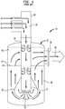
- In a conventional FTO shown generally at 10 in
FIG. 1 , air and a waste stream (a vent stream from another process) which may include organic and other particular material is introduced via a diptube into a preheated porous matrix. - As the air and waste stream expands through a matrix it absorbs heat from the ceramic until the stream reaches its auto-ignition temperature, at which point it starts to react, liberate heat and deliver heat back to the ceramic matrix. Such delivered heat is then transferred back through the ceramic matrix, by a combination of conduction, convection and radiation, serving to preheat a fresh waste stream and air entering the matrix via the diptube.
- In such a process, a self-sustaining oxidation process is achieved, and high peak flame temperatures observed in conventional combustion systems are avoided by the transfer of heat rapidly to the ceramic matrix.
- In particular, the FTO includes a
container 12 or vessel withinternal space 14 in which a hotceramic matrix 16 is disposed. A top of thecontainer 12 is provided with anopening 18 through which adiptube 20 or inlet diptube is inserted. - A
lower end 22 of thediptube 20 opens into theceramic matrix 16. An upper end of thediptube 20 above the opening 18 and external to thecontainer 12 is provided with a plurality ofinlets - The
inlets internal passage 30 extending through thediptube 20 to the lower end 22: - The inlet 24 is the vent or waste inlet for providing a waste stream from an upstream process (not shown) into the
internal passage 30 of thediptube 20. - The
inlet 26 is the air inlet introducing an air stream into theinternal passage 30 of thediptube 20. - The
inlet 28 is the fuel inlet for providing a fuel stream to theinternal passage 30 of thediptube 20. - All of the streams provided by the
inlets internal passage 30 and are discharged from thelower end 22 of thediptube 20 into the hotceramic matrix 16 which provides anoxidation zone 32 extending from thelower end 22 outward and upward along thediptube 20. Theoxidation zone 32 tapers to a reduced diameter and dissipates as it heats theceramic matrix 16 in thecontainer 12, as shown by thearrows 34. - The
container 12 is also provided with anoutlet 36 or exhaust in whichclean gas 38 is discharged from theullage 40 in thecontainer 12 above anupper surface 42 of theceramic matrix 16. That is, theoutlet 36 is in fluid communication with theullage 40 above thesurface 42 of theceramic matrix 16, such that the latter will not be exhausted through theoutlet 36 with theclean gas 38. - In effect, the vent or waste stream being introduced at the inlet 24 may contain organic and/or particulate matter which is combusted and/or filtered in the hot
ceramic matrix 16 and thereafter exhausted from theullage 40 above thematrix 16 and through theoutlet 36 to be discharged as theclean gas stream 38. - The gaseous waste stream-
air mixture 24, 26 has to be sufficiently reactive and have sufficient energy content to create products of combustion able to effectively heat the ceramic matrix and to preheat the incoming waste-air mixture. This is often accomplished by an adiabatic combustion temperature which can be readily calculated on a thermodynamic basis knowing the composition and temperature of the waste and air streams. - If the waste stream-air mixture is not sufficiently reactive and the products of combustion cannot be raised to the required temperature using the inherent enthalpy of combustion of the waste stream, then supplemental fuel may be added. However, the added fuel increases operating costs, and also increases emissions and a requirement for a larger reaction vessel, due to the increased volume of combustion products.
- Starting from the disadvantages and shortcomings as described above as well as taking the prior art as discussed into account, an object of the present invention is to overcome the limitations and problems that earlier apparatus and earlier methods have experienced.
- This object is accomplished by an apparatus comprising the features of claim 1 as well as by a method comprising the features of claim 8. Advantageous embodiments, expedient improvements and other optional features of the present invention are set forth herein and disclosed in the respective dependent claims.
- There is therefore provided a flameless thermal oxidizer (FTO) as well as a related method of operating a flameless thermal oxidizer.
- More particularly, the size of a flameless thermal oxidizer (FTO) is reduced by oxygen (O2) enhancement.
- Even more particularly, there is therefore provided herein to replace at least a portion of the air used in the flameless thermal oxidizer (FTO) to combust the waste stream with an oxygen rich stream, such that the combustion product temperature is increased without the need to use additional fuel.
- The present embodiments therefore reduce the volume of combustion products which results in either a smaller volume flameless thermal oxidizer (FTO) being used or a higher throughput through the existing flameless thermal oxidizers (FTO) while avoiding the need for additional fuel.
- A flameless thermal oxidizer (FTO) provided herein includes a container in which a ceramic matrix is contained and a diptube having a passageway extending therethrough, the diptube inserted or positioned in the ceramic matrix and in which a plurality of gaseous streams are present for combustion at the ceramic matrix, the plurality of gaseous streams including at least a vent stream and an oxygen stream.
- According to an advantageous embodiment of the present invention, the flameless thermal oxidizer may further comprise
- a first inlet connected to and in communication with the passageway for introducing the vent stream into the passageway, and
- a second inlet connected to and in communication with the passageway for introducing the oxygen stream into the passageway.
- In an expedient embodiment of the present invention, the first inlet may be separate from the second inlet.
- According to a favoured embodiment of the present invention, the second inlet may comprise a pipe sized and shaped to extend into and through a length of the passageway.
- In a preferred embodiment of the present invention, a distal end of the pipe may have an outlet upstream of an opening at a lower end of the diptube.
- According to an advantageous embodiment of the present invention, another pipe may be connected to and in communication with the passageway, the another pipe comprising an air stream therein for mixing with the oxygen stream in the another pipe for providing an oxygen-airstream mixture to be provided to the passageway.
- In an expedient embodiment of the present invention, another pipe may be connected to and in communication with the passageway, the another pipe comprising an air stream, a fuel stream, the vent stream, and the oxygen stream for providing a mixture to be provided to the passageway.
- A method of operating a flameless thermal oxidizer includes introducing a plurality of gaseous streams into a heated ceramic matrix contained within the flameless thermal oxidizer, the plurality of gaseous streams including at least a vent stream and an oxygen stream.
- According to a favoured embodiment of the present invention, the vent stream and the oxygen stream may be introduced separately.
- In a preferred embodiment of the present invention, mixing the vent stream and the oxygen stream may be mixed after the introducing.
- According to an advantageous embodiment of the present invention, the plurality of gaseous streams may further comprise an air stream and a fuel stream.
- In an expedient embodiment of the present invention, the vent, oxygen, air and the fuel streams may be introduced separately.
- According to a favoured embodiment of the present invention, the separately provided vent, oxygen, air and fuel streams may be mixed for providing a mixed stream, and the mixed stream may be introduced into the heated ceramic matrix.
- In a preferred embodiment of the present invention, the air stream and the oxygen stream may be mixed for providing an air-oxygen mixture upstream of the vent and fuel streams, and the air-oxygen mixture may be introduced into the vent and fuel streams.
- According to an advantageous embodiment of the present invention, the oxygen stream may be introduced into the vent stream proximate the ceramic matrix.
- For a more complete understanding of the present embodiment disclosures and as already discussed above, there are several options to embody as well as to improve the teaching of the present invention in an advantageous manner. To this aim, reference may be made to the claims dependent on claim 1 as well as on claim 8; further improvements, features and advantages of the present invention are explained below in more detail with reference to the particular and preferred embodiments by way of non-limiting example and to the appended drawing figures taken in conjunction with the following description of exemplary embodiments, of which:
- FIG. 1
- shows a side view in cross-section of a known flameless thermal oxidizer (FTO);
- FIG. 2
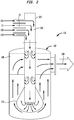
- shows a side view in cross-section of a first embodiment of a flameless thermal oxidizer (FTO) according to the present invention, said embodiment working according to the method of the present invention;
- FIG. 3
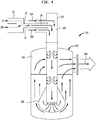
- shows a side view in cross-section of another embodiment of a flameless thermal oxidizer (FTO) according to the present invention, said embodiment working according to the method of the present invention;
- FIG. 4
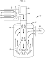
- shows a side view in cross-section of still another embodiment of a flameless thermal oxidizer (FTO) according to the present invention, said embodiment working according to the method of the present invention; and
- FIG. 5
- shows a side view in cross-section of still another embodiment of a flameless thermal oxidizer (FTO) according to the present invention, said embodiment working according to the method of the present invention.
- The accompanying drawings are included to provide a further understanding of the apparatus and method(s) provided herein and are incorporated in and constitute a part of this specification. The drawings illustrate various embodiments of the apparatus and method(s) provided herein and, together with the description, serve to explain the principles described herein but are not intended to limit the specification or any of the claims.
- Before explaining the present inventive embodiments in detail, it is to be understood that the embodiments are not limited in its respective application to the details of construction and arrangement of parts illustrated in the accompanying drawings, since the present invention is capable of other embodiments and of being practiced or carried out in various ways. Also, it is to be understood that the phraseology or terminology employed herein is for the purpose of description and not of limitation.
- In the following description, terms such a horizontal, upright, vertical, above, below, beneath and the like, are used solely for the purpose of clarity illustrating the present invention and should not be taken as words of limitation. The drawings are for the purpose of illustrating the present invention and are not intended to be to scale.
- The present embodiments include a system where an increased oxygen concentration (greater than that found in air) is used to provide the desired combustion temperature without using additional fuel and air and, in fact, reduces the overall volume of the products of combustion. As such, either an increase in capacity for the same volume reactor or a smaller reactor is needed for the same throughput. This will result in capital cost savings.
- Referring to
FIG. 2 to FIG. 5 , four embodiments of an FTO are shown according to the present invention. Four exemplary embodiments of an FTO constructed in accordance with the present invention are illustrated inFIG. 2 to FIG. 5 , respectively. Elements illustrated inFIG. 2 to FIG. 5 which correspond to the elements described above with respect toFIG. 1 have been designated by corresponding reference signs increased by 100, 200, 300 and 400 compared toFIG. 1 , respectively. - In order to avoid unnecessary repetitions, the explanations above and below relate to all four of the exemplary embodiments of the present invention illustrated in
FIG. 2 to FIG. 5 with respect to the configurations, features and advantages of the present invention, unless otherwise stated. The embodiments ofFIG. 2 to FIG. 5 are designed for use in the same manner as the embodiment ofFIG. 1 unless otherwise stated: - Referring to the embodiment shown at
FIG. 2 , a pure oxygen (O2)stream 11 is introduced into aseparate inlet 13 which is connected to and in communication with aninternal passage 130 of an inlet diptube ordiptube 120. The oxygen (O2)stream 11 mixes in theinternal passage 130 with inlet streams, namely with a vent or waste stream, with an air stream, and with a fuel stream. - The flameless thermal oxidizer (FTO) 110 according to the first embodiment shown in
FIG. 2 includes acontainer 112 or vessel with an internal space in which a hot ceramic matrix is disposed. A top of thecontainer 112 is provided with an opening through which thediptube 120 is inserted. - A lower end of the
diptube 120 opens into the ceramic matrix. An upper end of thediptube 120 above the opening and external to thecontainer 112 is provided with the plurality ofinlets - The
inlets internal passage 130 extending through thediptube 120 to the lower end: - The
inlet 124 is the vent or waste inlet for providing the vent or waste stream from an upstream process (not shown) into theinternal passage 130 of thediptube 120. - The
inlet 13 is the oxygen inlet introducing theoxygen stream 11 into theinternal passage 130 of thediptube 120. - The
inlet 126 is the air inlet introducing the air stream into theinternal passage 130 of thediptube 120. - The
inlet 128 is the fuel inlet for providing the fuel stream to theinternal passage 130 of thediptube 120. - All of the streams provided by the
inlets internal passage 130 and are discharged from the lower end of thediptube 120 into the hot ceramic matrix which provides anoxidation zone 132 extending from the lower end outward and upward along thediptube 120. Theoxidation zone 132 tapers to a reduced diameter and dissipates as it heats the ceramic matrix in thecontainer 112, as shown by the arrows inFIG. 2 . - The
container 112 is also provided with an outlet or exhaust in whichclean gas 138 is discharged from theullage 140 in thecontainer 112 above an upper surface of the ceramic matrix. That is, the outlet is in fluid communication with theullage 140 above the surface of the ceramic matrix, such that the latter will not be exhausted through the outlet with theclean gas 138. - In effect, the vent or waste stream being introduced at the inlet may contain organic and/or particulate matter which is combusted and/or filtered in the hot ceramic matrix and thereafter exhausted from the
ullage 140 above the matrix and through the outlet to be discharged as theclean gas stream 138. - Three other exemplary embodiments of an FTO constructed in accordance with the present invention are illustrated in
FIG. 3 to FIG. 5 , respectively. Elements illustrated inFIG. 3 to Fig. 5 which correspond to the elements described above with respect toFIG. 2 have been designated by corresponding reference signs increased by 100, 200 and 300 compared toFIG. 2 , respectively. The embodiments ofFIG. 3 to FIG. 5 are designed for use in the same manner as the embodiment ofFIG. 2 unless otherwise stated. - Referring to
FIG. 3 , this second embodiment of a flameless thermal oxidizer (FTO) 210 is provided with a pure oxygen (O2)stream 15 introduced through aninlet pipe 17 which is sized and shaped for extending into and through a substantial length of theinternal passage 230 of thediptube 220. - As shown in
FIG. 3 , alower end 19 of theinlet pipe 17 opens at an outlet prior to or upstream of an opening at thelower end 222 of thediptube 220. This provides for mixing of the oxygen (O2)stream 15 with the inlet streams 224, 226, 228 prior to being exhausted into theoxidation zone 232. - In the third embodiment of a flameless thermal oxidizer (FTO) 310 shown in
FIG. 4 , a pure oxygen (O2)stream 21 and theinlet stream 326 for the air are combined in a pipe 23 which has anoutlet 25 for the combined oxygen-airstream 27 to be introduced at aninlet 29 in gaseous communication with theinternal passage 330 of thediptube 320. The oxygen-air stream 27 mixes with thevent stream 324 and thefuel stream 328 in theinternal passage 330. - In the fourth embodiment of a flameless thermal oxidizer (FTO) 410 shown in
FIG. 5 , a pure oxygen (O2)stream 31 is mixed with the inlet streams 424, 426, 428 in apipe 33 having anoutlet 35 connected to and in communication with theinternal passage 430 of thediptube 420. - The
pipe 33 is external to thediptube 420, wherein a construction of the pipe permits the pure oxygen (O2)stream 31 and the inlet streams 424, 426, 428 to be mixed together as shown generally at 37 whereupon saidmixture 37 is introduced into theinternal passage 430. - The oxygen (O2) concentration in the
streams - The oxygen rich streams of the embodiments in
FIG. 2 to FIG. 5 may also be a by-product stream or vent stream from for example a nitrogen generator. - As discussed above, the oxygen enriched stream may be mixed with the air prior to the diptube, mixed with the air-waste mixture prior to the diptube, or kept separate from the other streams until the discharge opening at the lower end of the diptube.
- The foregoing embodiments of
FIG. 2 to FIG. 5 provide for: - a reduction in reactor size for given capacity/throughput and therefore, capital cost savings occur;
- an increase in reactor throughput and therefore, increased productivity;
- a reduction in supplemental fuel and therefore, reduced operating costs; and
- allowance of processing of low C[alorific]V[alues] or energy values or heating values / of low heat wastes or BTU wastes that would not normally be used in a flameless thermal oxidizer (FTO)and therefore, increased flexibility.
- The present embodiments may be used for example to process vent streams from processes such as for example a nitrogen generator.
- It will be understood that the embodiments described herein are merely exemplary, and that one skilled in the art may make variations and modifications without departing from the spirit and scope of the present invention. All such variations and modifications are intended to be included within the scope of the present invention as described and claimed herein. Further, all embodiments disclosed are not necessarily in the alternative, as various embodiments of the present invention may be combined to provide the desired result.
-
- 10
- flameless thermal oxidizer (FTO) (prior art; cf.
FIG. 1 ) - 12
- container or vessel
- 14
- internal space
- 16
- ceramic matrix, in particular hot ceramic matrix
- 18
- opening
- 20
- diptube, in particular inlet diptube
- 22
- lower end of
diptube 20 - 24
- first inlet, in particular vent inlet or waste inlet
- 26
- air inlet
- 28
- fuel inlet
- 30
- passageway or internal passage of
diptube 20 - 32
- oxidation zone
- 34
- heating of
ceramic matrix 16 - 36
- outlet or exhaust
- 38
- clean gas, in particular clean gas stream
- 40
- ullage
- 42
- upper surface of
ceramic matrix 16 - 110
- flameless thermal oxidizer (FTO) (first embodiment; cf.
FIG. 2 ) - 11
- oxygen (O2), in particular oxygen (O2) inlet stream
- 13
- second inlet, in particular for
oxygen 11 - 112
- container or vessel
- 120
- diptube, in particular inlet diptube
- 124
- first inlet, in particular vent inlet or waste inlet
- 126
- air inlet
- 128
- fuel inlet
- 130
- passageway or internal passage of
diptube 120 - 132
- oxidation zone
- 138
- clean gas, in particular clean gas stream
- 140
- ullage
- 210
- flameless thermal oxidizer (FTO) (second embodiment; cf.
FIG. 3 ) - 15
- oxygen (O2), in particular oxygen (O2) inlet stream
- 17
- second inlet, in particular inlet pipe for
oxygen 15 - 19
- lower end
- 212
- container or vessel
- 220
- diptube, in particular inlet diptube
- 222
- lower end of
diptube 220 - 224
- first inlet, in particular vent inlet or waste inlet
- 226
- air inlet
- 228
- fuel inlet
- 230
- passageway or internal passage of
diptube 220 - 232
- oxidation zone
- 238
- clean gas, in particular clean gas stream
- 240
- ullage
- 310
- flameless thermal oxidizer (FTO) (third embodiment; cf.
FIG. 4 ) - 21
- oxygen (O2), in particular oxygen (O2) inlet stream
- 23
- pipe for oxygen-
air stream mixture 27 - 25
- outlet of pipe 23
- 27
- oxygen-air stream mixture
- 29
- inlet
- 312
- container or vessel
- 320
- diptube, in particular inlet diptube
- 324
- first inlet, in particular vent inlet or waste inlet
- 326
- air inlet
- 328
- fuel inlet
- 330
- passageway or internal passage of
diptube 320 - 332
- oxidation zone
- 338
- clean gas, in particular clean gas stream
- 340
- ullage
- 410
- flameless thermal oxidizer (FTO) (fourth embodiment; cf.
FIG. 5 ) - 31
- oxygen (O2), in particular oxygen (O2) inlet stream
- 33
- pipe for oxygen-vent/waste-air-
fuel stream mixture 37 - 35
- outlet of
pipe 33 - 37
- oxygen-vent/waste-air-fuel stream mixture
- 412
- container or vessel
- 420
- diptube, in particular inlet diptube
- 424
- first inlet, in particular vent inlet or waste inlet
- 426
- air inlet
- 428
- fuel inlet
- 430
- passageway or internal passage of
diptube 420 - 432
- oxidation zone
- 438
- clean gas, in particular clean gas stream
- 440
- ullage
Claims (15)
- A flameless thermal oxidizer (110; 210; 310; 410), comprising:- a container (112; 212; 312; 412) in which a ceramic matrix is contained; and- a diptube (120; 220; 320; 420) having a passageway (130; 230; 330; 430) extending therethrough, the diptube (120; 220; 320; 420) inserted or positioned in the ceramic matrix and in which a plurality of gaseous streams are present for combustion at the ceramic matrix, the plurality of gaseous streams including a vent stream and an oxygen stream.
- The flameless thermal oxidizer according to claim 1, further comprising:- a first inlet (124; 224; 324; 424) connected to and in communication with the passageway (130; 230; 330; 430) for introducing the vent stream into the passageway (130; 230; 330; 430), and- a second inlet (13; 17) connected to and in communication with the passageway (130; 230; 330; 430) for introducing the oxygen stream into the passageway (130; 230; 330; 430).
- The flameless thermal oxidizer according to claim 2, wherein the first inlet (124) is separate from the second inlet (13).
- The flameless thermal oxidizer according to claim 2 or 3, wherein the second inlet (17) comprises a pipe sized and shaped to extend into and through a length of the passageway (230).
- The flameless thermal oxidizer according to claim 4, wherein a distal end of the pipe has an outlet upstream of an opening at a lower end (222) of the diptube (220).
- The flameless thermal oxidizer according to at least one of claims 1 to 5, further comprising another pipe (23) connected to and in communication with the passageway (330), the another pipe (23) comprising an air stream therein for mixing with the oxygen stream in the another pipe (23) for providing an oxygen-air stream mixture (27) to be provided to the passageway (330).
- The flameless thermal oxidizer according to at least one of claims 1 to 6, further comprising another pipe (33) connected to and in communication with the passageway (430), the another pipe (33) comprising an air stream, a fuel stream, the vent stream, and the oxygen stream for providing an oxygen-vent-air-fuel stream mixture (37) to be provided to the passageway (430).
- A method of operating a flameless thermal oxidizer (110; 210; 310; 410), comprising introducing a plurality of gaseous streams into a heated ceramic matrix contained within the flameless thermal oxidizer (110; 210; 310; 410), the plurality of gaseous streams including at least a vent stream and an oxygen stream.
- The method according to claim 8, wherein the vent stream and the oxygen stream are introduced separately.
- The method according to claim 8 or 9, further comprising mixing (27) the vent stream and the oxygen stream after the introducing.
- The method according to at least one of claims 8 to 10, wherein the plurality of gaseous streams further comprises an air stream and a fuel stream.
- The method according to claim 11, wherein the vent, oxygen, air and the fuel streams are introduced separately.
- The method according to claim 12, further comprising mixing (37) the separately provided vent, oxygen, air and fuel streams for providing a mixed stream, and introducing the mixed stream into the heated ceramic matrix.
- The method according to at least one of claims 11 to 13, further comprising mixing the air stream and the oxygen stream for providing an air-oxygen mixture upstream of the vent and fuel streams, and introducing the air-oxygen mixture into the vent and fuel streams.
- The method according to at least one of claims 8 to 14, further comprising introducing the oxygen stream into the vent stream proximate the ceramic matrix.
Applications Claiming Priority (2)
| Application Number | Priority Date | Filing Date | Title |
|---|---|---|---|
| US201662359272P | 2016-07-07 | 2016-07-07 | |
| US15/636,853 US20180010789A1 (en) | 2016-07-07 | 2017-06-29 | Reducing the size of a flameless thermal oxidizer by oxygen enhancement |
Publications (1)
| Publication Number | Publication Date |
|---|---|
| EP3267103A1 true EP3267103A1 (en) | 2018-01-10 |
Family
ID=59295095
Family Applications (1)
| Application Number | Title | Priority Date | Filing Date |
|---|---|---|---|
| EP17180066.7A Withdrawn EP3267103A1 (en) | 2016-07-07 | 2017-07-06 | Flameless thermal oxidizer and corresponding method |
Country Status (2)
| Country | Link |
|---|---|
| US (1) | US20180010789A1 (en) |
| EP (1) | EP3267103A1 (en) |
Families Citing this family (1)
| Publication number | Priority date | Publication date | Assignee | Title |
|---|---|---|---|---|
| US10272385B2 (en) | 2016-05-17 | 2019-04-30 | Linde Engineering North America, Inc. | Flameless thermal oxidizer for oxidizing gaseous effluent streams containing hydrogen gas |
Citations (3)
| Publication number | Priority date | Publication date | Assignee | Title |
|---|---|---|---|---|
| US4823711A (en) * | 1987-08-21 | 1989-04-25 | In-Process Technology, Inc. | Thermal decomposition processor and system |
| US6003305A (en) * | 1997-09-02 | 1999-12-21 | Thermatrix, Inc. | Method of reducing internal combustion engine emissions, and system for same |
| US20110283991A1 (en) * | 2008-03-11 | 2011-11-24 | Peter Falcone | System and method for flameless thermal oxidation at optimized equivalance ratios |
-
2017
- 2017-06-29 US US15/636,853 patent/US20180010789A1/en not_active Abandoned
- 2017-07-06 EP EP17180066.7A patent/EP3267103A1/en not_active Withdrawn
Patent Citations (3)
| Publication number | Priority date | Publication date | Assignee | Title |
|---|---|---|---|---|
| US4823711A (en) * | 1987-08-21 | 1989-04-25 | In-Process Technology, Inc. | Thermal decomposition processor and system |
| US6003305A (en) * | 1997-09-02 | 1999-12-21 | Thermatrix, Inc. | Method of reducing internal combustion engine emissions, and system for same |
| US20110283991A1 (en) * | 2008-03-11 | 2011-11-24 | Peter Falcone | System and method for flameless thermal oxidation at optimized equivalance ratios |
Also Published As
| Publication number | Publication date |
|---|---|
| US20180010789A1 (en) | 2018-01-11 |
Similar Documents
| Publication | Publication Date | Title |
|---|---|---|
| CN1107838C (en) | Improvements in the combustion and utilisation of fuel gases | |
| KR950007381B1 (en) | Low nox high efficiency combustion process | |
| US4797087A (en) | Method and apparatus for generating highly luminous flame | |
| US7832365B2 (en) | Submerged combustion vaporizer with low NOx | |
| US8202470B2 (en) | Low NOx fuel injection for an indurating furnace | |
| NO328141B1 (en) | Apparatus and method for mixing at least two fluid streams | |
| EP0432153A1 (en) | DEVICE AND METHOD FOR PRODUCING A HIGHLIGHT GIVING FLAME. | |
| AU2012294314B8 (en) | Low NOx Fuel injection for an indurating furnace | |
| EP3044509B1 (en) | Combustion method and industrial burner | |
| CN109000272A (en) | A kind of the bitumen flue gas processing system and processing method of heat recovery | |
| US20180010789A1 (en) | Reducing the size of a flameless thermal oxidizer by oxygen enhancement | |
| US7959431B2 (en) | Radiant tube with recirculation | |
| CN117433313A (en) | Furnace operation method | |
| US10895380B2 (en) | Flameless thermal oxidizer for oxidizing gaseous effluent streams containing hydrogen gas | |
| JP2020535381A (en) | burner | |
| DE102005005735B4 (en) | Method for heating an industrial furnace using a burner and tube-in-tube burners suitable for carrying out the method | |
| US20100244337A1 (en) | NOx Suppression Techniques for an Indurating Furnace | |
| EP4163543B1 (en) | Regenerative burner system and method of use | |
| WO2003031662A1 (en) | Process and apparatus for the treatment of contaminated fumes | |
| EP1812352B1 (en) | Method for supercritical water oxidation of a stream containing oxidizable material | |
| WO2019055335A1 (en) | Low steam consumption high smokeless capacity waste gas flare | |
| CN208936178U (en) | A kind of bitumen flue gas processing system of heat recovery | |
| RU2052726C1 (en) | Waste gas afterburning device | |
| SE533731C2 (en) | Procedure for combustion of low-grade fuel | |
| EP2488797B1 (en) | Low emissions direct fired air heater |
Legal Events
| Date | Code | Title | Description |
|---|---|---|---|
| PUAI | Public reference made under article 153(3) epc to a published international application that has entered the european phase |
Free format text: ORIGINAL CODE: 0009012 |
|
| STAA | Information on the status of an ep patent application or granted ep patent |
Free format text: STATUS: THE APPLICATION HAS BEEN PUBLISHED |
|
| AK | Designated contracting states |
Kind code of ref document: A1 Designated state(s): AL AT BE BG CH CY CZ DE DK EE ES FI FR GB GR HR HU IE IS IT LI LT LU LV MC MK MT NL NO PL PT RO RS SE SI SK SM TR |
|
| AX | Request for extension of the european patent |
Extension state: BA ME |
|
| STAA | Information on the status of an ep patent application or granted ep patent |
Free format text: STATUS: REQUEST FOR EXAMINATION WAS MADE |
|
| 17P | Request for examination filed |
Effective date: 20180710 |
|
| RBV | Designated contracting states (corrected) |
Designated state(s): AL AT BE BG CH CY CZ DE DK EE ES FI FR GB GR HR HU IE IS IT LI LT LU LV MC MK MT NL NO PL PT RO RS SE SI SK SM TR |
|
| STAA | Information on the status of an ep patent application or granted ep patent |
Free format text: STATUS: EXAMINATION IS IN PROGRESS |
|
| 17Q | First examination report despatched |
Effective date: 20200219 |
|
| RAP1 | Party data changed (applicant data changed or rights of an application transferred) |
Owner name: LINDE GMBH |
|
| STAA | Information on the status of an ep patent application or granted ep patent |
Free format text: STATUS: THE APPLICATION IS DEEMED TO BE WITHDRAWN |
|
| 18D | Application deemed to be withdrawn |
Effective date: 20220201 |