EP3267021A1 - Engine and method of manufacturing cylinder block of engine - Google Patents
Engine and method of manufacturing cylinder block of engine Download PDFInfo
- Publication number
- EP3267021A1 EP3267021A1 EP17178634.6A EP17178634A EP3267021A1 EP 3267021 A1 EP3267021 A1 EP 3267021A1 EP 17178634 A EP17178634 A EP 17178634A EP 3267021 A1 EP3267021 A1 EP 3267021A1
- Authority
- EP
- European Patent Office
- Prior art keywords
- crank
- cylinder
- cylinder hole
- shaft
- offset
- Prior art date
- Legal status (The legal status is an assumption and is not a legal conclusion. Google has not performed a legal analysis and makes no representation as to the accuracy of the status listed.)
- Withdrawn
Links
- 238000004519 manufacturing process Methods 0.000 title claims description 15
- 238000013459 approach Methods 0.000 claims abstract description 7
- 239000004575 stone Substances 0.000 claims description 34
- 238000000034 method Methods 0.000 claims description 24
- 238000012545 processing Methods 0.000 description 14
- 238000005266 casting Methods 0.000 description 11
- 238000003754 machining Methods 0.000 description 9
- 238000005520 cutting process Methods 0.000 description 8
- 238000004512 die casting Methods 0.000 description 7
- 229910052782 aluminium Inorganic materials 0.000 description 5
- XAGFODPZIPBFFR-UHFFFAOYSA-N aluminium Chemical compound [Al] XAGFODPZIPBFFR-UHFFFAOYSA-N 0.000 description 5
- 230000013011 mating Effects 0.000 description 5
- 229910052751 metal Inorganic materials 0.000 description 5
- 239000002184 metal Substances 0.000 description 5
- 230000000694 effects Effects 0.000 description 3
- 238000000465 moulding Methods 0.000 description 3
- 238000005192 partition Methods 0.000 description 3
- 230000015572 biosynthetic process Effects 0.000 description 2
- 238000003780 insertion Methods 0.000 description 2
- 230000037431 insertion Effects 0.000 description 2
- 229910001018 Cast iron Inorganic materials 0.000 description 1
- 238000004891 communication Methods 0.000 description 1
- 239000000498 cooling water Substances 0.000 description 1
- 230000007423 decrease Effects 0.000 description 1
- 230000002950 deficient Effects 0.000 description 1
- 230000001419 dependent effect Effects 0.000 description 1
- 230000005484 gravity Effects 0.000 description 1
- 238000005461 lubrication Methods 0.000 description 1
- 239000000463 material Substances 0.000 description 1
- 230000005855 radiation Effects 0.000 description 1
- 230000003014 reinforcing effect Effects 0.000 description 1
- 239000004576 sand Substances 0.000 description 1
Images





Classifications
-
- F—MECHANICAL ENGINEERING; LIGHTING; HEATING; WEAPONS; BLASTING
- F02—COMBUSTION ENGINES; HOT-GAS OR COMBUSTION-PRODUCT ENGINE PLANTS
- F02F—CYLINDERS, PISTONS OR CASINGS, FOR COMBUSTION ENGINES; ARRANGEMENTS OF SEALINGS IN COMBUSTION ENGINES
- F02F7/00—Casings, e.g. crankcases
- F02F7/0095—Constructing engine casings
-
- B—PERFORMING OPERATIONS; TRANSPORTING
- B23—MACHINE TOOLS; METAL-WORKING NOT OTHERWISE PROVIDED FOR
- B23B—TURNING; BORING
- B23B35/00—Methods for boring or drilling, or for working essentially requiring the use of boring or drilling machines; Use of auxiliary equipment in connection with such methods
-
- B—PERFORMING OPERATIONS; TRANSPORTING
- B23—MACHINE TOOLS; METAL-WORKING NOT OTHERWISE PROVIDED FOR
- B23B—TURNING; BORING
- B23B51/00—Tools for drilling machines
- B23B51/10—Bits for countersinking
- B23B51/102—Back spot-facing or chamfering
-
- B—PERFORMING OPERATIONS; TRANSPORTING
- B23—MACHINE TOOLS; METAL-WORKING NOT OTHERWISE PROVIDED FOR
- B23C—MILLING
- B23C3/00—Milling particular work; Special milling operations; Machines therefor
- B23C3/12—Trimming or finishing edges, e.g. deburring welded corners
-
- F—MECHANICAL ENGINEERING; LIGHTING; HEATING; WEAPONS; BLASTING
- F02—COMBUSTION ENGINES; HOT-GAS OR COMBUSTION-PRODUCT ENGINE PLANTS
- F02F—CYLINDERS, PISTONS OR CASINGS, FOR COMBUSTION ENGINES; ARRANGEMENTS OF SEALINGS IN COMBUSTION ENGINES
- F02F1/00—Cylinders; Cylinder heads
- F02F1/18—Other cylinders
-
- F—MECHANICAL ENGINEERING; LIGHTING; HEATING; WEAPONS; BLASTING
- F02—COMBUSTION ENGINES; HOT-GAS OR COMBUSTION-PRODUCT ENGINE PLANTS
- F02F—CYLINDERS, PISTONS OR CASINGS, FOR COMBUSTION ENGINES; ARRANGEMENTS OF SEALINGS IN COMBUSTION ENGINES
- F02F7/00—Casings, e.g. crankcases
- F02F7/0002—Cylinder arrangements
- F02F7/0019—Cylinders and crankshaft not in one plane (deaxation)
-
- B—PERFORMING OPERATIONS; TRANSPORTING
- B23—MACHINE TOOLS; METAL-WORKING NOT OTHERWISE PROVIDED FOR
- B23B—TURNING; BORING
- B23B2215/00—Details of workpieces
- B23B2215/24—Components of internal combustion engines
-
- B—PERFORMING OPERATIONS; TRANSPORTING
- B23—MACHINE TOOLS; METAL-WORKING NOT OTHERWISE PROVIDED FOR
- B23B—TURNING; BORING
- B23B2265/00—Details of general geometric configurations
- B23B2265/12—Eccentric
-
- B—PERFORMING OPERATIONS; TRANSPORTING
- B23—MACHINE TOOLS; METAL-WORKING NOT OTHERWISE PROVIDED FOR
- B23C—MILLING
- B23C2210/00—Details of milling cutters
- B23C2210/20—Number of cutting edges
- B23C2210/202—Number of cutting edges three
-
- B—PERFORMING OPERATIONS; TRANSPORTING
- B23—MACHINE TOOLS; METAL-WORKING NOT OTHERWISE PROVIDED FOR
- B23C—MILLING
- B23C2215/00—Details of workpieces
- B23C2215/24—Components of internal combustion engines
-
- B—PERFORMING OPERATIONS; TRANSPORTING
- B23—MACHINE TOOLS; METAL-WORKING NOT OTHERWISE PROVIDED FOR
- B23C—MILLING
- B23C2220/00—Details of milling processes
- B23C2220/16—Chamferring
-
- B—PERFORMING OPERATIONS; TRANSPORTING
- B23—MACHINE TOOLS; METAL-WORKING NOT OTHERWISE PROVIDED FOR
- B23C—MILLING
- B23C2265/00—Details of general geometric configurations
- B23C2265/12—Eccentric
-
- F—MECHANICAL ENGINEERING; LIGHTING; HEATING; WEAPONS; BLASTING
- F02—COMBUSTION ENGINES; HOT-GAS OR COMBUSTION-PRODUCT ENGINE PLANTS
- F02F—CYLINDERS, PISTONS OR CASINGS, FOR COMBUSTION ENGINES; ARRANGEMENTS OF SEALINGS IN COMBUSTION ENGINES
- F02F2200/00—Manufacturing
- F02F2200/06—Casting
Definitions
- the present invention relates to an engine in which a honing stone escape portion is formed in a cylinder block, and a method of manufacturing the cylinder block of the engine of this type.
- a cylinder hole of an engine is processed by honing.
- the honing process is performed by moving a honing stone rotating in the cylinder hole back and forth along the central line of the cylinder hole.
- the honing stone goes through the cylinder hole and projects by a predetermined length into a crank chamber from the cylinder hole.
- the honing stone should project into the crank chamber in order to evenly polish the cylinder hole over the entire length, thereby increasing the precision of the cylindricality of the cylinder hole.
- a cylinder block of a multi-cylinder engine includes a cylinder wall with a cylinder hole, a crank case that forms a crank chamber together with an oil pan, and a bearing wall that extends toward a crank shaft from the ceiling wall of the crank case between cylinders.
- a cylinder-side half portion of a bearing for supporting the crank shaft is formed on the distal end portion of the bearing wall.
- the cylinder spacing is narrowed as much as possible in order to achieve downsizing in the axial direction of the crank shaft. Therefore, the above-described bearing wall is often positioned close to the cylinder hole.
- the bearing wall partially overlaps the cylinder hole when viewed in a direction parallel to the central line of the cylinder. This is because the whole bearing wall is formed to have the thickness of a bearing portion having the largest thickness so that the bearing wall is releasable from the metal mold, since, in aluminum die casting, a molten metal is injected into a metal mold at such a high speed and high pressure that it is difficult to use a sand core.
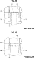
- Fig. 14 is a sectional view showing a part of a cylinder block 102 in an enlarged scale.
- reference numeral 103 denotes a cylinder hole; and 104, a bearing wall positioned between cylinders.
- the honing stone escape process is performed by inserting a rotary cutting tool 101 between the bearing walls 104, and rotating the rotary cutting tool 101 held in a predetermined position.
- the rotary cutting tool 101 has a retractable blade (not shown), and rotates with this blade being projected. The rotating blade cuts the bearing walls 104.
- the rotary cutting tool 101 chamfers a crank-shaft-side opening edge of the cylinder hole 103. By the chamfering process, an inclined surface 108 is formd on the crank-shaft-side opening edge of the cylinder hole 103.
- some conventional multi-cylinder engines have an offset crank as a crank shaft.
- This offset crank is a crank shaft having an axis which is offset from the central line of the cylinder hole.
- a connecting rod is biased in an offset direction of the crank shaft. In the offset direction, the spacing between the crank-shaft-side opening edge of the cylinder hole and the connecting rod is narrowed, and this may cause interference.
- the interference between the crank-shaft-side opening edge of the cylinder hole and the connecting rod is avoided by using the following method.
- the interference avoiding method are a method by which a recess for avoiding the connecting rod is integrally molded by casting on the crank-shaft-side opening edge of the cylinder hole, and a method which performs casting such that the position of the crank-shaft-side opening edge of the cylinder hole is raised over the entire circumference.
- the recess for avoiding the connecting rod is formed by using a metal mold for molding the cylinder block.
- An offset crank type engine poses the following problem if the method of integrally molding the recess on the crank-shaft-side opening edge of the cylinder hole by casting is adopted in order to avoid the interference between the crank-shaft-side opening edge of the cylinder hole and the connecting rod. That is, when the crank-shaft-side opening edge of the cylinder hole is chamfered after casting, the formed inclined surface becomes intermittent by the recess, and a processing edge or burr forms in this intermittent portion.
- said object is solved by an engine according to the independent claim 1. Moreover, said object is solved by a method of manufacturing a cylinder block of an engine according to the independent claim 3. Preferred embodiments are laid down in the dependent claims.
- an offset crank type engine in which the entire circumference of the crank-shaft-side opening edge of a cylinder hole can be chamfered without adopting any arrangement having a bad influence on the sliding surface and posture of a piston, in order to avoid interference between the crank-shaft-side opening edge of the cylinder hole and a connecting rod.
- an engine that comprises a cylinder block including a cylinder hole into which a piston is movably fitted, a crank shaft as an offset crank, an axis of which is offset from a central line of the cylinder hole, and a connecting rod configured to connect the piston and the crank shaft to each other, wherein an inclined surface is formed on an entire circumference of a crank-shaft-side opening edge of the cylinder hole, and when viewed in an axial direction of the crank shaft, a boundary line between the inclined surface and the cylinder hole approaches the other end of the cylinder hole as going toward an offset side on which the crank shaft is offset from the central line.
- an engine cylinder block manufacturing method comprising a cylinder block including a cylinder hole into which a piston is movably fitted, and a crank shaft as an offset crank, an axis of which is offset from a central line of the cylinder hole, the method including a chamfering step of performing chamfering on an entire circumference of a crank-shaft-side opening edge of the cylinder hole by using a cutter which rotates around an axis parallel to the central line, wherein the chamfering is performed by moving the cutter along the crank-shaft-side opening edge, and a moving amount of a rotation center of the cutter which moves in the chamfering step is larger on one side on which the crank shaft is offset from the central line of the cylinder hole, than on the other side, when viewed in a direction of the axis of the crank shaft.
- an engine cylinder block manufacturing method comprising a cylinder block having a cylinder hole into which a piston is movably fitted, and a crank shaft as an offset crank, an axis of which is offset from a central line of the cylinder hole, the method including a chamfering step of performing chamfering on an entire circumference of a crank-shaft-side opening edge of the cylinder hole by using a cutter which rotates around an axis parallel to the central line, wherein the chamfering is performed in a state in which a rotation center of the cutter stays in a position biased in an offset direction of the crank shaft with respect to the central line.
- a cylinder block 1 shown in Fig. 1 is a cylinder block of a multi-cylinder engine, and formed into a predetermined shape by gravity die casting using cast iron as a material and a sand mold or core (not shown).
- the cylinder block 1 has three functional portions.
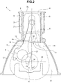
- the first functional portion is a cylinder wall 3 having a plurality cylinder holes 2. As shown in Fig. 2 , a piston 4 is movably fitted into the cylinder hole 2. Fig. 2 shows the piston 4 positioned in the top dead center, and the piston 4 positioned in the bottom dead center.
- Fig. 2 omits a crank web, crank pin, and the like of the crank shaft 6, and shows only a crank journal by the alternate long and two short dashed line.
- the crank shaft 6 is a so-called offset crank.
- an axis C1 of the crank shaft 6 is offset by a length L1 to one side (the left side in Fig. 2 ) with respect to a central line C2 of the cylinder hole 2. Therefore, the outermost moving locus of the connecting rod 5 has a shape biased to the left side in Fig. 2 , as indicated by an alternate long and two short dashed line A in Fig. 2 .
- one side on which the crank shaft 6 is offset will simply be called “an offset side”, and the side opposite to this direction will be called “the other side”.
- a mating surface 8 for attaching a cylinder head (not shown) is formed on one end portion (the upper end portion in Fig. 1 ) of the cylinder wall 3.
- one end (the upper side in Figs. 1 and 2 ) of the cylinder wall 3 will be called “a cylinder head side”, and the other end thereof will be called “a crank shaft side”.
- a cooling water passage 9 is formed in that portion of the cylinder wall 3, which covers the cylinder hole 2.
- An inclined surface 11 is formed by chamfering (to be described later) on a portion which is the crank-shaft-side end portion of the cylinder wall 3 and is an crank-shaft-side opening edge 10 of the cylinder hole 2. Details of this chamfering will be described later. Note that this chamfering is performed before the cylinder hole 2 is honed.
- the second functional portion of the cylinder block 1 is a crank case 13 having a ceiling wall 12 connected to the crank-shaft-side end portion of the cylinder wall 3.
- the crank case 13 is formed into a boxy shape which opens toward the side opposite to the cylinder wall 3. This opening of the crank case 13 is closed with an oil pan (not shown).
- the crank case 13 and oil pan form a crank chamber 14 for accommodating the crank shaft 6.
- a portion connecting the ceiling wall 12 and the crank-shaft-side end portion of the cylinder wall 3, in other words, a portion surrounding the crank-shaft-side opening edge 10 of the cylinder hole 2 is formed by a first wall 15 positioned on the offset side, and a second wall 16 positioned on the other side.
- the first and second walls 15 and 16 are formed into a predetermined shape by a mold for casting the cylinder block 1.
- the first wall 15 does not contribute to guiding of the piston 4, and hence is positioned closer to the cylinder head side than the second wall 16.
- the first wall 15 is thus formed to be biased toward the cylinder head side, a space S is formed between the moving locus of the connecting rod 5 indicated by the alternate long and two short dashed line A and the first wall 15 (the crank-shaft-side opening edge 10 of the cylinder hole 2), when viewed in the axial direction of the crank shaft 6.
- the length the first wall 15 is spaced apart from the second wall 16 toward the cylinder head side in the direction parallel to the central line C2 of the cylinder hole 2 is a length which does not spoil the function of guiding a skirt 4a (see Fig. 2 ) of the piston 4 by the wall surface of the cylinder hole 2.
- the third functional portion is a bearing wall 17 extending from the ceiling wall 12 toward the crank shaft 6.
- the bearing portion 17 includes a plate-like portion 17a extending in a direction perpendicular to the axis of the crank shaft 6, and a bearing portion 17b formed in the crank-shaft-side end portion of the plate-like portion 17a.
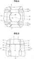
- the bearing wall 17 is formed between the cylinder holes 2 adjacent to each other when viewed in the direction parallel to the central axis C2 of the cylinder hole 2.
- the plate-like portion 17a of the bearing wall 17 is formed to have a thickness equal to that of a partition 18 between the cylinder holes 2.
- the partition 18 is a part of the cylinder wall 3.
- a plurality of reinforcing ribs 19 are integrated with the plate-like portion 17a according to this embodiment.
- the plate-like portion 17a is formed to have a size which partitions the crank chamber 14 for the individual cylinders.
- First to third communication holes 20 to 22 which allow those inner spaces of the crank chamber 14, which are partitioned for the individual cylinders, to communicate with each other are formed in the plate-like portion 17a.
- a honing stone escape portion 23 is formed in the cylinder-head-side end portion of the plate-like portion 17a, which overlaps the central line C2 of the cylinder hole 2 when viewed in the axial direction of the crank shaft 6 as shown in Fig. 1 .
- the honing stone escape portion 23 is a recess for avoiding contact with a honing stone 24 inserted into the cylinder hole 2 in order to perform honing.
- the honing stone escape portion 23 is formed when performing chamfering (to be described later) on the crank-shaft-side opening edge 10 of the cylinder hole 2.
- the honing stone escape portion 23 and a chamfered portion can be formed by using a sand core during casting. However, the surfaces are rough as cast and may damage the piston 4, so cutting is performed on them.
- the bearing portion 17b is formed to be thicker than the plate-like portion 17a. As shown in Fig. 4 , therefore, the bearing portion 17b partially overlaps the cylinder hole 2 when viewed in the direction parallel to the central line C2 of the cylinder hole 2. As shown in Fig. 1 , a bearing cap 25 is attached to the bearing portion 17b. The crank shaft 6 is sandwiched between the bearing portion 17b and the bearing cap 25 and rotatably supported by these members.
- chamfering performed on the crank-shaft-side opening edge 10 of the cylinder hole 2 is performed in chamfering step S3 after casting step S1 and machining step S2.
- This flowchart of Fig. 8 shows an example of a method of manufacturing the cylinder block 1.
- the cylinder block 1 is manufactured by performing casting step S1, chamfering step S3, and honing step S4 in this order.
- Casting step S1 is a step of molding the cylinder block 1 by casting.
- Machining step S2 is a step of cutting mating surfaces, passages, holes, and the like by machining, and performing threading. Machining step S2 includes prepared hole machining before honing.
- Chamfering step S3 is performed by using a cutter 31 shown in Figs. 3 and 6 .
- the cutter 31 includes a plurality of blades 32, and a rotational shaft 33 for supporting the blades 32.
- the rotational shaft 33 is driven by a driving device (not shown), and rotates around an axis C3 (see Fig. 3 ) parallel to the central line C2 of the cylinder hole 2.
- the cutter 31 shown in Figs. 3 and 6 has three blades 32.
- the number of blades 32 is not limited to three and can be changed as needed.
- the plurality of blades 32 can be arranged so as to extend, e.g., in the radial direction from the rotational shaft 33.
- the blades 32 are formed to have a size which can be inserted into the cylinder hole 2 from the cylinder-head-side end portion.
- the rotation locus forms a circle smaller than the cylinder hole 2 as indicated by an alternate long and two short dashed line B in Fig. 6 when viewed in the axial direction of the rotational shaft 33.
- the blade 32 has a predetermined length in the direction parallel to the central line C2 of the cylinder hole 2, and includes an inclining chamfering portion 32a formed on one end portion as the cylinder head side, and an escape processing portion 32b extending toward the other end portion from the chamfering portion 32a.
- the chamfering portion 32a so inclines as to be gradually positioned toward the other end portion of the blade 32 in the direction away from the axis C3 of the cutter 31.
- the escape processing portion 32b extends parallel to the central line C2 of the cylinder hole 2.
- the length of the escape processing portion 32b matches the size and reciprocation stroke of the honing stone 24 to be used in honing step S4 next to chamfering step S3.
- the length of the escape portion 32b is desirably larger than the length the honing stone 24 projects toward the crank shaft 6 from the cylinder hole 2.
- chamfering step S3 a plurality of steps shown in a flowchart of Fig. 9 are executed in order.
- insertion step S11 is first performed, i.e., the cutter 31 is inserted into the cylinder hole 2 from the opening of the cylinder-head-side end portion.
- positioning step S12 the cutter 31 is positioned such that the chamfered portion 32a is positioned in the boundary between the cylinder hole 2 and the crank chamber 14, as shown in Fig. 3 .
- Fig. 3 shows the cylinder block 1 in a state after chamfering step S3.
- the driving device drives the rotational shaft 33, and the cutter 31 rotates around the rotational shaft 33.
- revolution step S14 after that, the cutter 31 moves along a predetermined moving path.
- This movement is performed by the driving device by changing the position of the rotational shaft 33 in the direction perpendicular to the central line C2 of the cylinder hole 2.
- the moving path of the cutter 31 is a path by which a circle indicated by an alternate long and two short dashed line C in Fig. 6 is the moving locus.
- this moving path is a path which forms a moving locus indicated by an alternate long and two short dashed line D in Fig. 3 .
- a center C4 of the circle indicated by the alternate long and two short dashed line C in Fig. 6 is in the same position as that of the center (the position of the central line C2) of the cylinder hole 2 in the axial direction of the crank shaft 6, and spaced apart by a length L2 toward the offset side (the left side in Fig.
- a radius r of the circle as the moving locus indicated by the alternate long and two short dashed line C in Fig. 6 is set at a radius by which the chamfering portion 32a of the blade 32 can cut the crank-shaft-side opening edge 10 of the cylinder hole 2 on the offset side (the left side in Fig. 3 ) and on the opposite side.
- the moving amount of the rotation center (the position of the axis C3) of the cutter 31 which moves in revolution step S14 is D1 on the offset side (the left side in Fig. 3 ), and D2 on the other side, with respect to the central line C2 of the cylinder hole 2.
- the moving amount D1 is larger than the moving amount D2. That is, the rotation center of the cutter 31 moves to the offset side longer than to the other side with respect to the central line C2 of the cylinder hole 2.
- the chamfering portion 32a cuts the crank-shaft-side opening edge 10 of the cylinder hole 2 over the entire circumference.
- revolution step S14 the cutter 31 moves along the crank-shaft-side opening edge 10 of the cylinder hole 2, and chamfers the whole crank-shaft-side opening edge 10. Since the crank-shaft-side opening edge 10 of the cylinder hole 2 is thus chamfered, the inclined surface 11 is formed on this opening edge over the entire circumference.
- a boundary line 34 between the inclined surface 11 and the cylinder hole 2 inclines upward to the left in Fig. 3 .
- the inclining direction of the boundary line 34 is a direction in which the boundary line 34 gradually approaches the opening 2a in the other end of the cylinder hole 2 toward the offset side on which the crank shaft 6 is offset from the central line C2 of the cylinder hole 2, when viewed in the axial direction of the crank shaft 6.
- the inclining direction of the boundary line 34 is a direction in which, as shown in Fig.
- the boundary line 34 approaches a virtual line 36 including a perpendicular 35 extending from the axis C1 of the crank shaft 6 to the central line C2 of the cylinder hole 2, in the direction from the offset side to the other side (the right side in Fig. 3 ) when viewed in the axial direction of the crank shaft 6.
- the width (the width in the vertical direction in Fig. 3 ) of the inclined surface 11 in the direction parallel to the central line C2 of the cylinder hole 2 gradually increases toward the offset side.
- the reason for this is that the inclined chamfering portion 32a of the cutter 31 gradually cuts the crank-shaft-side opening edge 10 on the offset side deeply in the radial direction.
- the first wall 15 is biased toward the cylinder head more than the second wall 16, so the width of the inclined surface 11 shown in Fig. 3 decreases halfway.
- revolution step S14 since in revolution step S14 the cutter 31 moves along the moving locus indicated by the alternate long and two short dashed line C in Fig. 6 , the bearing wall 17 is partially cut by the escape processing portion 32b of the cutter 31, thereby forming the honing stone escape portion 23 on the bearing wall 17. That is, in revolution step S14, the above-described inclined surface 11 and the honing stone escape portion 23 of the bearing wall 17 are simultaneously processed by the cutter 31. As shown in Figs. 1 and 7 , the processed inclined surface 11 is so connected as to continue to the honing stone escape portion 23.
- the process advances to rotation stop step S15, and the driving device stops driving the rotational shaft 33, thereby stopping the cutter 31.
- removal step S16 after that, the cutter 31 is moved from the position of rotation stop to a removal position on the side of the central line C2 of the cylinder hole 2, and removed outside the cylinder block 1 through the cylinder hole 2.
- Chamfering step S3 is complete when the cutter 31 thus retracts.
- honing step S4 is performed after chamfering step S3.
- the honing stone 24 goes back and forth in the cylinder hole 2 while rotating.
- the honing stone 24 does not interfere with the bearing wall 17 because the honing stone escape portion 23 is formed on the bearing wall 17.
- the inclined surface 11 formed on the crank-shaft-side opening edge 10 of the cylinder hole 2 so inclines as to gradually approach the opening 2a in the other end (the cylinder head side) of the cylinder hole 2 in the direction of the offset side, when viewed in the axial direction of the crank shaft 6.
- the end portion of the inclined surface 11 on the offset side is also a portion to which the connecting rod 5 comes closest.
- the boundary line 34 of the inclined surface 11 is close to the opening in the other end of the cylinder hole 2, and this means that the spacing between the crank-shaft-side opening edge 10 of the cylinder hole 2 and the connecting rod 5 increases. This makes it possible to avoid interference between the crank-shaft-side opening edge 10 of the cylinder hole 2 and the connecting rod 5 by the inclined surface 11.
- the above-described boundary line 34 indicates a position corresponding to the limit of the range within which the piston 4 is guided near the bottom dead center. That is, since only the guide of the piston 4 near the bottom dead center gradually reduces toward the offset side, the posture of the piston 4 does not become unstable near the bottom dead center.
- the whole circumference of the crank-shaft-side opening edge 10 of the cylinder hole 2 is chamfered. Therefore, the skirt 4a of the piston 4 passing through this opening edge is not damaged by a burr or fine projection.
- this embodiment can provide an offset crank type engine in which the whole circumference of the crank-shaft-side opening edge 10 of the cylinder hole 2 can be chamfered without adopting any inconvenient arrangement when avoiding interference between the crank-shaft-side opening edge 10 of the cylinder hole 2 and the connecting rod 5.
- the "inconvenient arrangement” is an arrangement which exerts a bad influence on the sliding surface or posture of the piston 4, e.g., the formation of a recess in the crank-shaft-side opening edge or raising the position of the crank-shaft-side opening edge over the entire circumference as in a conventional arrangement.
- the inclined surface 11 according to this embodiment is so connected as to continue to the honing stone escape portion 23. This makes it possible to reliably prevent contact with the bearing wall 17 when the piston 4 or honing stone 24 projects toward the crank shaft 6 from the cylinder hole 2.
- the bearing wall 17 can be arranged close to the central line C2 of the cylinder 2 while avoiding interference with the piston 4 or honing stone 24, so the cylinder block 1 can be shortened in the axial direction of the crank shaft 6. Consequently, this embodiment can provide an engine formed to be compact in the axial direction of the crank shaft 6.
- the piston 4 does not come in contact with that portion of the cylinder hole 2, which is closer to the crank shaft side than the boundary line 34 of the inclined surface 11, so this portion has no function of guiding the piston 4 near the bottom dead center.
- the first wall 15 positioned on the offset side is formed in the position biased to the cylinder head side more than the second wall 16.
- This arrangement shortens the time required for the cutting process when forming the inclined surface 11 compared to an arrangement in which the first wall 15 and second wall 16 are formed to have the same height, so the productivity increases.
- Chamfering according to this embodiment is performed by using the cutter 31 having a diameter smaller than the diameter of the cylinder hole 2. Therefore, the cutter 31 can be inserted into the cylinder hole 2 from the cylinder-head-side opening of the cylinder hole 2, and hence can be positioned with high accuracy by using the cylinder-head-side mating surface 8 of the cylinder block 1. As a consequence, the crank-shaft-side opening edge 10 of the cylinder hole 2 can accurately be chamfered.
- Chamfering step S3 is performed by using the cutter 31 having a predetermined length in the direction parallel to the central line C2 of the cylinder 2.
- chamfering step S3 the crank-shaft-side opening edge 10 of the cylinder 2 and the bearing wall 17 are simultaneously processed by the cutter 31.
- the chamfering step (chamfering and the processing of the honing stone escape portion) can also be performed as shown in Figs. 10 and 11 .
- the same reference numerals as in Figs. 1 to 9 denote the same members as explained with reference to Figs. 1 to 9 or similar members, and a detailed explanation thereof will suitably be omitted.
- a plurality of blades 43 radially projecting from a rotatable shaft 42 can move in the radial direction of the rotatable shaft 42.
- An axis C5 of the rotatable shaft 42 is arranged in a processing position spaced apart by a predetermined length to the offset side (the left side in Fig. 10 ) from a central axis C2 of a cylinder hole 2, and the rotatable shaft 42 rotates by being driven by a driving device (not shown) in this processing position.
- the plurality of blades 43 include a chamfering portion 43a and an escape processing portion 43b like the blade 32 disclosed in the first embodiment.
- the blades 43 are pushed outward in the radial direction by a pushing mechanism 44 formed in the rotatable shaft 42, and project outward in the radiation direction from the rotatable shaft 42 while being supported by the rotatable shaft 42.
- a pushing mechanism 44 it is possible to use, e.g., a pushing mechanism disclosed in literature 1.
- Chamfering step S3 is performed as shown in a flowchart of Fig. 11 .
- the cutter 41 is first inserted into the cylinder hole 2 from the cylinder head side (insertion step S21), and positioned in the boundary portion between the cylinder hole 2 and a crank chamber 14 (positioning step S22).
- positioning step S22 the rotatable shaft 42 of the cutter 41 is positioned in the above-described processing position.
- the escape processing portion 43b of the blade 43 cuts a bearing wall 17, thereby forming a honing stone escape portion 23 on the shaft wall 17.
- An alternate long and two short dashed line D in Fig. 3 indicates the outer shape of the cutter 41 when this machining is complete.
- machining step S23 After machining step S23 is complete, the rotation of the cutter 41 stops, and the blades 43 of the cutter 41 retract inward in the radial direction of the rotatable shaft 42. Then, in removal step S24, the cutter 41 is removed outside the cylinder block 1 through the cylinder hole 2. Chamfering step S3 is complete when the cutter 41 thus retracts.
- this embodiment can shorten the processing time because the position of the cutter 41 remains unchanged. Therefore, this embodiment can provide a highly productive engine cylinder block manufacturing method.
- Fig. 12 shows a bearing wall 17 of a cylinder block 1 formed by aluminum die casting.
- the same reference numerals as in Figs. 1 to 9 denote the same members as explained with reference to Figs. 1 to 9 or similar members, and a detailed explanation thereof will suitably be omitted.
- a plate-like portion 17a of the bearing wall 17 shown in Fig. 12 is formed into a shape releasable from a metal mold, as explained with reference to Fig. 14 as the related art at the beginning of this specification, and is so formed as to have a thickness equal to or larger than that of a bearing portion 17b.
- a honing stone escape portion 23 is formed on the plate-like portion 17a by being cut by a cutter (not shown) as explained in the first or second embodiment.
- an inclined surface 11 is formed on a crank-shaft-side opening edge 10 of a cylinder hole 2.
- the present teaching is thus also applicable to an engine including the cylinder block 1 formed by aluminum die casting, and can achieve the same effects as those obtained by adopting the above-described embodiments.
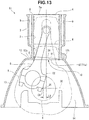
- the present teaching can also provide an arranged as shown in Fig. 13 .
- the same reference numerals as in Figs. 1 to 12 denote the same members as explained with reference to Figs. 1 to 12 or similar members, and a detailed explanation thereof will suitably be omitted.
- a portion surrounding a crank-shaft-side opening edge 10 of a cylinder hole 2 differs from that of the cylinder block 1 according to the above-described embodiments, and the rest is the same.
- the portion surrounding the crank-shaft-side opening edge 10 of the cylinder hole 2 is formed by a flat third wall 52.
- the thickness of the third wall 52 is constant.
- a ceiling wall 12 of a crank case 13 is formed to have practically the same height in one end portion 12a as the offset side and another end portion 12b, when viewed in the axial direction of a crank shaft 6.
- the "height" herein mentioned is equivalent to a position in a direction parallel to a central line C2 of the cylinder hole 2.
- an edge 11 a of an inclined surface 11 on the crank shaft side linearly extends between the offset side and the other side when viewed in the axial direction of the crank shaft 6.
- the inclined surface 11 can be formed by using a cutter (not shown) as explained in the first or second embodiment.
- the connecting rod comes closest to the end portion of the inclined surface on the offset side.
- the boundary line of this inclined surface is close to the opening in the other end of the cylinder hole, and this means that the spacing between the crank-shaft-side opening edge of the cylinder hold and the connecting rod increases. This makes it possible to avoid interference between the crank-shaft-side opening edge of the cylinder hole and the connecting rod by the inclined surface.
- the above-described boundary line indicates a position corresponding to the limit of the range within which the piston is guided near the bottom dead center. That is, since only the guide of the piston near the bottom dead center gradually reduces toward the offset side, the posture of the piston does not become unstable near the bottom dead center.
- the whole circumference of the crank-shaft-side opening edge of the cylinder hole is chamfered. Therefore, the skirt of the piston passing through this opening edge is not damaged by a burr or fine projection.
- the present teaching can provide an offset crank type engine in which the whole circumference of the crank-shaft-side opening edge of the cylinder hole can be chamfered without adopting any arrangement which exerts a bad influence on the sliding surface or posture of the piston, e.g., the formation of a recess in the crank-shaft-side opening edge or raising the position of the crank-shaft-side opening edge over the entire circumference as in a conventional arrangement, when avoiding interference between the crank-shaft-side opening edge of the cylinder hole and the connecting rod.
- a cutter having a diameter smaller than that of the cylinder hole can be used. Since, therefore, the cutter can be inserted into the cylinder hole from that opening of the cylinder hole, which is opposite to the crank shaft, the cutter can be positioned with high accuracy by using the cylinder-head-side mating surface of the cylinder block. As a consequence, the crank-shaft-side opening edge of the cylinder hole can accurately be chamfered.
- the processing time can be shortened compared to a method of performing chamfering while moving the cutter. This makes it possible to provide a highly productive engine cylinder block manufacturing method.
Landscapes
- Engineering & Computer Science (AREA)
- Mechanical Engineering (AREA)
- Chemical & Material Sciences (AREA)
- Combustion & Propulsion (AREA)
- General Engineering & Computer Science (AREA)
- Cylinder Crankcases Of Internal Combustion Engines (AREA)
- Milling Processes (AREA)
Abstract
An engine includes a cylinder block (1) including a cylinder hole (2), a crank shaft (6) as an offset crank, and a connecting rod (5) for connecting the piston (4) and the crank shaft (6). An inclined surface (11) is formed on the entire circumference of a crank-shaft-side opening edge of one end of the cylinder hole (2). When viewed in the axial direction of the crank shaft (6), a boundary line (34) between the inclined surface (11) and the cylinder hole (2) approaches the other end of the cylinder hole (2) as going toward an offset side on which the crank shaft (6) is offset from the central line of the cylinder hole (2). This invention can provide an offset crank type engine in which the entire circumference of the crank-shaft-side opening edge of the cylinder hole can be chamfered without adopting any arrangement having a bad influence on the sliding surface and posture of the piston, in order to avoid interference between the crank-shaft-side opening edge of the cylinder hole and the connecting rod.
Description
- The present invention relates to an engine in which a honing stone escape portion is formed in a cylinder block, and a method of manufacturing the cylinder block of the engine of this type.
- Conventionally, a cylinder hole of an engine is processed by honing. The honing process is performed by moving a honing stone rotating in the cylinder hole back and forth along the central line of the cylinder hole. During the honing, the honing stone goes through the cylinder hole and projects by a predetermined length into a crank chamber from the cylinder hole. The honing stone should project into the crank chamber in order to evenly polish the cylinder hole over the entire length, thereby increasing the precision of the cylindricality of the cylinder hole.
- A cylinder block of a multi-cylinder engine includes a cylinder wall with a cylinder hole, a crank case that forms a crank chamber together with an oil pan, and a bearing wall that extends toward a crank shaft from the ceiling wall of the crank case between cylinders. A cylinder-side half portion of a bearing for supporting the crank shaft is formed on the distal end portion of the bearing wall.
- In a recent multi-cylinder engine, the cylinder spacing is narrowed as much as possible in order to achieve downsizing in the axial direction of the crank shaft. Therefore, the above-described bearing wall is often positioned close to the cylinder hole. When an engine cylinder block like this is formed by aluminum die casting, the bearing wall partially overlaps the cylinder hole when viewed in a direction parallel to the central line of the cylinder. This is because the whole bearing wall is formed to have the thickness of a bearing portion having the largest thickness so that the bearing wall is releasable from the metal mold, since, in aluminum die casting, a molten metal is injected into a metal mold at such a high speed and high pressure that it is difficult to use a sand core.
- If the bearing wall extends toward the cylinder hole as described above, honing process cannot be performed without performing honing stone escape process on the bearing wall, as describe in, for example, Japanese Patent Laid-Open No.
2015-161189 literature 1 hereinafter). As shown inFig. 14 , the honing stone escape process is performed by using arotary cutting tool 101.Fig. 14 is a sectional view showing a part of acylinder block 102 in an enlarged scale. InFig. 14 ,reference numeral 103 denotes a cylinder hole; and 104, a bearing wall positioned between cylinders. The honing stone escape process is performed by inserting arotary cutting tool 101 between thebearing walls 104, and rotating therotary cutting tool 101 held in a predetermined position. Therotary cutting tool 101 has a retractable blade (not shown), and rotates with this blade being projected. The rotating blade cuts thebearing walls 104. - After the honing stone escape process, as shown in
Fig. 15 , some parts of thebearing walls 104 are partially removed to form honingstone escape portions 105 are formed as recesses on thebearing walls 104. In the honing stone escape process, as shown inFig. 16 , therotary cutting tool 101 chamfers a crank-shaft-side opening edge of thecylinder hole 103. By the chamfering process, aninclined surface 108 is formd on the crank-shaft-side opening edge of thecylinder hole 103. - Also, some conventional multi-cylinder engines have an offset crank as a crank shaft. This offset crank is a crank shaft having an axis which is offset from the central line of the cylinder hole. In an engine using the offset crank, a connecting rod is biased in an offset direction of the crank shaft. In the offset direction, the spacing between the crank-shaft-side opening edge of the cylinder hole and the connecting rod is narrowed, and this may cause interference.
- In the conventional engine of this type, the interference between the crank-shaft-side opening edge of the cylinder hole and the connecting rod is avoided by using the following method. Examples of the interference avoiding method are a method by which a recess for avoiding the connecting rod is integrally molded by casting on the crank-shaft-side opening edge of the cylinder hole, and a method which performs casting such that the position of the crank-shaft-side opening edge of the cylinder hole is raised over the entire circumference. The recess for avoiding the connecting rod is formed by using a metal mold for molding the cylinder block.
- An offset crank type engine poses the following problem if the method of integrally molding the recess on the crank-shaft-side opening edge of the cylinder hole by casting is adopted in order to avoid the interference between the crank-shaft-side opening edge of the cylinder hole and the connecting rod. That is, when the crank-shaft-side opening edge of the cylinder hole is chamfered after casting, the formed inclined surface becomes intermittent by the recess, and a processing edge or burr forms in this intermittent portion.
- If a piston goes back and forth in the cylinder hole with the processing edge or burr being formed as described above, the sliding surface of the skirt of the piston is easily damaged. If the sliding surface of the piston is damaged, defective lubrication may occur and cause piston seizure.
- When casting is performed such that the position of the crank-shaft-side opening edge of the cylinder hole is raised over the entire circumference in order to avoid the interference between the opening edge and the connecting rod, the guide of the piston reduces near the bottom dead center, and the posture of the piston may become unstable and generate noise.
- It is an object of the present invention to provide an engine and a method of manufacturing a cylinder block of an engine with a sliding surface and posture of a piston, in order to avoid interference between the crank-shaft-side opening edge of the cylinder hole and a connecting rod.
- According to the present invention said object is solved by an engine according to the
independent claim 1. Moreover, said object is solved by a method of manufacturing a cylinder block of an engine according to theindependent claim 3. Preferred embodiments are laid down in the dependent claims. - Accordingly, it is provided an offset crank type engine in which the entire circumference of the crank-shaft-side opening edge of a cylinder hole can be chamfered without adopting any arrangement having a bad influence on the sliding surface and posture of a piston, in order to avoid interference between the crank-shaft-side opening edge of the cylinder hole and a connecting rod.
- Accordingly, it is provided an engine that comprises a cylinder block including a cylinder hole into which a piston is movably fitted, a crank shaft as an offset crank, an axis of which is offset from a central line of the cylinder hole, and a connecting rod configured to connect the piston and the crank shaft to each other, wherein an inclined surface is formed on an entire circumference of a crank-shaft-side opening edge of the cylinder hole, and when viewed in an axial direction of the crank shaft, a boundary line between the inclined surface and the cylinder hole approaches the other end of the cylinder hole as going toward an offset side on which the crank shaft is offset from the central line.
- Moreover, it is also provided an engine cylinder block manufacturing method, the engine comprising a cylinder block including a cylinder hole into which a piston is movably fitted, and a crank shaft as an offset crank, an axis of which is offset from a central line of the cylinder hole, the method including a chamfering step of performing chamfering on an entire circumference of a crank-shaft-side opening edge of the cylinder hole by using a cutter which rotates around an axis parallel to the central line, wherein the chamfering is performed by moving the cutter along the crank-shaft-side opening edge, and a moving amount of a rotation center of the cutter which moves in the chamfering step is larger on one side on which the crank shaft is offset from the central line of the cylinder hole, than on the other side, when viewed in a direction of the axis of the crank shaft.
- Moreover, it is also provided an engine cylinder block manufacturing method, the engine comprising a cylinder block having a cylinder hole into which a piston is movably fitted, and a crank shaft as an offset crank, an axis of which is offset from a central line of the cylinder hole, the method including a chamfering step of performing chamfering on an entire circumference of a crank-shaft-side opening edge of the cylinder hole by using a cutter which rotates around an axis parallel to the central line, wherein the chamfering is performed in a state in which a rotation center of the cutter stays in a position biased in an offset direction of the crank shaft with respect to the central line.
-
-
Fig. 1 is a sectional view of a cylinder block according to a preferred embodiment; -
Fig. 2 is a sectional view for explaining the arrangement of the cylinder block; -
Fig. 3 is a sectional view showing main parts in an enlarged scale; -
Fig. 4 is a view showing the bottom surface of a bearing wall; -
Fig. 5 is a sectional view showing the bearing wall sideways; -
Fig. 6 is a plan view showing a cylinder wall in a state in which a cutter according to the first embodiment is inserted; -
Fig. 7 is a perspective view showing a state in which a crank-shaft-side opening edge of a cylinder hole is viewed from the side of a crank chamber; -
Fig. 8 is a flowchart for explaining a cylinder block manufacturing method; -
Fig. 9 is a flowchart for explaining a chamfering step according to the first embodiment; -
Fig. 10 is a plan view showing a cylinder wall in a state in which a cutter according to the second embodiment is inserted; -
Fig. 11 is a flowchart for explaining a chamfering step according to the second embodiment; -
Fig. 12 is a sectional view showing a bearing wall according to the third embodiment sideways; -
Fig. 13 is a sectional view for explaining the arrangement of a cylinder block according to the fourth embodiment; -
Fig. 14 is a sectional view showing a state before escape process is performed on a conventional bearing wall; -
Fig. 15 is a sectional view showing a state after escape process is performed on the conventional bearing wall; and -
Fig. 16 is a sectional view showing a state after the crank-shaft-side opening edge of a conventional cylinder hole is chamfered. - An embodiment of an engine and a method of manufacturing a cylinder block of the engine will be explained in detail below with reference to
Figs. 1 to 9 . - A
cylinder block 1 shown inFig. 1 is a cylinder block of a multi-cylinder engine, and formed into a predetermined shape by gravity die casting using cast iron as a material and a sand mold or core (not shown). Thecylinder block 1 has three functional portions. - The first functional portion is a
cylinder wall 3 having aplurality cylinder holes 2. As shown inFig. 2 , apiston 4 is movably fitted into thecylinder hole 2.Fig. 2 shows thepiston 4 positioned in the top dead center, and thepiston 4 positioned in the bottom dead center. - The
piston 4 is connected to a crankshaft 6 by a connectingrod 5.Fig. 2 omits a crank web, crank pin, and the like of thecrank shaft 6, and shows only a crank journal by the alternate long and two short dashed line. - The
crank shaft 6 is a so-called offset crank. When viewed in the axial direction as shown inFig. 2 , an axis C1 of thecrank shaft 6 is offset by a length L1 to one side (the left side inFig. 2 ) with respect to a central line C2 of thecylinder hole 2. Therefore, the outermost moving locus of the connectingrod 5 has a shape biased to the left side inFig. 2 , as indicated by an alternate long and two short dashed line A inFig. 2 . In the following description, one side on which thecrank shaft 6 is offset will simply be called "an offset side", and the side opposite to this direction will be called "the other side". - A
mating surface 8 for attaching a cylinder head (not shown) is formed on one end portion (the upper end portion inFig. 1 ) of thecylinder wall 3. Anopening 2a of thecylinder hole 2, which is positioned on the side opposite to the crankshaft 6, is formed in themating surface 8. For the sake of convenience, one end (the upper side inFigs. 1 and2 ) of thecylinder wall 3 will be called "a cylinder head side", and the other end thereof will be called "a crank shaft side". - A cooling
water passage 9 is formed in that portion of thecylinder wall 3, which covers thecylinder hole 2. - An
inclined surface 11 is formed by chamfering (to be described later) on a portion which is the crank-shaft-side end portion of thecylinder wall 3 and is an crank-shaft-side opening edge 10 of thecylinder hole 2. Details of this chamfering will be described later. Note that this chamfering is performed before thecylinder hole 2 is honed. - The second functional portion of the
cylinder block 1 is acrank case 13 having aceiling wall 12 connected to the crank-shaft-side end portion of thecylinder wall 3. The crankcase 13 is formed into a boxy shape which opens toward the side opposite to thecylinder wall 3. This opening of thecrank case 13 is closed with an oil pan (not shown). The crankcase 13 and oil pan form acrank chamber 14 for accommodating thecrank shaft 6. - As shown in
Figs. 1 to 3 and7 , a portion connecting theceiling wall 12 and the crank-shaft-side end portion of thecylinder wall 3, in other words, a portion surrounding the crank-shaft-side opening edge 10 of thecylinder hole 2 is formed by afirst wall 15 positioned on the offset side, and asecond wall 16 positioned on the other side. The first andsecond walls cylinder block 1. As will be described in detail later, thefirst wall 15 does not contribute to guiding of thepiston 4, and hence is positioned closer to the cylinder head side than thesecond wall 16. As shown inFig. 3 , since thefirst wall 15 is thus formed to be biased toward the cylinder head side, a space S is formed between the moving locus of the connectingrod 5 indicated by the alternate long and two short dashed line A and the first wall 15 (the crank-shaft-side opening edge 10 of the cylinder hole 2), when viewed in the axial direction of thecrank shaft 6. Note that the length thefirst wall 15 is spaced apart from thesecond wall 16 toward the cylinder head side in the direction parallel to the central line C2 of thecylinder hole 2 is a length which does not spoil the function of guiding askirt 4a (seeFig. 2 ) of thepiston 4 by the wall surface of thecylinder hole 2. - As shown in
Fig. 1 , the third functional portion is a bearingwall 17 extending from theceiling wall 12 toward thecrank shaft 6. As shown inFig. 1 , the bearingportion 17 includes a plate-like portion 17a extending in a direction perpendicular to the axis of thecrank shaft 6, and a bearingportion 17b formed in the crank-shaft-side end portion of the plate-like portion 17a. - As shown in
Fig. 4 , the bearingwall 17 is formed between the cylinder holes 2 adjacent to each other when viewed in the direction parallel to the central axis C2 of thecylinder hole 2. As shown inFig. 5 , the plate-like portion 17a of the bearingwall 17 is formed to have a thickness equal to that of apartition 18 between the cylinder holes 2. Thepartition 18 is a part of thecylinder wall 3. - As shown in
Fig. 1 , a plurality of reinforcingribs 19 are integrated with the plate-like portion 17a according to this embodiment. Also, the plate-like portion 17a is formed to have a size which partitions thecrank chamber 14 for the individual cylinders. First to third communication holes 20 to 22 which allow those inner spaces of thecrank chamber 14, which are partitioned for the individual cylinders, to communicate with each other are formed in the plate-like portion 17a. - A honing
stone escape portion 23 is formed in the cylinder-head-side end portion of the plate-like portion 17a, which overlaps the central line C2 of thecylinder hole 2 when viewed in the axial direction of thecrank shaft 6 as shown inFig. 1 . The honingstone escape portion 23 is a recess for avoiding contact with a honingstone 24 inserted into thecylinder hole 2 in order to perform honing. The honingstone escape portion 23 is formed when performing chamfering (to be described later) on the crank-shaft-side opening edge 10 of thecylinder hole 2. The honingstone escape portion 23 and a chamfered portion (to be described later) can be formed by using a sand core during casting. However, the surfaces are rough as cast and may damage thepiston 4, so cutting is performed on them. - As shown in
Fig. 5 , the bearingportion 17b is formed to be thicker than the plate-like portion 17a. As shown inFig. 4 , therefore, the bearingportion 17b partially overlaps thecylinder hole 2 when viewed in the direction parallel to the central line C2 of thecylinder hole 2. As shown inFig. 1 , abearing cap 25 is attached to the bearingportion 17b. Thecrank shaft 6 is sandwiched between the bearingportion 17b and thebearing cap 25 and rotatably supported by these members. - As shown in a flowchart of
Fig. 8 , chamfering performed on the crank-shaft-side opening edge 10 of thecylinder hole 2 is performed in chamfering step S3 after casting step S1 and machining step S2. This flowchart ofFig. 8 shows an example of a method of manufacturing thecylinder block 1. Thecylinder block 1 is manufactured by performing casting step S1, chamfering step S3, and honing step S4 in this order. Casting step S1 is a step of molding thecylinder block 1 by casting. Machining step S2 is a step of cutting mating surfaces, passages, holes, and the like by machining, and performing threading. Machining step S2 includes prepared hole machining before honing. - Chamfering step S3 is performed by using a
cutter 31 shown inFigs. 3 and6 . Thecutter 31 includes a plurality ofblades 32, and arotational shaft 33 for supporting theblades 32. Therotational shaft 33 is driven by a driving device (not shown), and rotates around an axis C3 (seeFig. 3 ) parallel to the central line C2 of thecylinder hole 2. - The
cutter 31 shown inFigs. 3 and6 has threeblades 32. However, the number ofblades 32 is not limited to three and can be changed as needed. The plurality ofblades 32 can be arranged so as to extend, e.g., in the radial direction from therotational shaft 33. Also, theblades 32 are formed to have a size which can be inserted into thecylinder hole 2 from the cylinder-head-side end portion. - When the
cutter 31 rotates around therotational shaft 33, the rotation locus forms a circle smaller than thecylinder hole 2 as indicated by an alternate long and two short dashed line B inFig. 6 when viewed in the axial direction of therotational shaft 33. - As shown in
Fig. 3 , theblade 32 has a predetermined length in the direction parallel to the central line C2 of thecylinder hole 2, and includes an incliningchamfering portion 32a formed on one end portion as the cylinder head side, and anescape processing portion 32b extending toward the other end portion from thechamfering portion 32a. - The
chamfering portion 32a so inclines as to be gradually positioned toward the other end portion of theblade 32 in the direction away from the axis C3 of thecutter 31. Theescape processing portion 32b extends parallel to the central line C2 of thecylinder hole 2. The length of theescape processing portion 32b matches the size and reciprocation stroke of the honingstone 24 to be used in honing step S4 next to chamfering step S3. The length of theescape portion 32b is desirably larger than the length the honingstone 24 projects toward thecrank shaft 6 from thecylinder hole 2. - In chamfering step S3, a plurality of steps shown in a flowchart of
Fig. 9 are executed in order. When performing chamfering step S3, insertion step S11 is first performed, i.e., thecutter 31 is inserted into thecylinder hole 2 from the opening of the cylinder-head-side end portion. In positioning step S12, thecutter 31 is positioned such that the chamferedportion 32a is positioned in the boundary between thecylinder hole 2 and thecrank chamber 14, as shown inFig. 3 . Note thatFig. 3 shows thecylinder block 1 in a state after chamfering step S3. - Subsequently, in rotation start step S13, the driving device drives the
rotational shaft 33, and thecutter 31 rotates around therotational shaft 33. - In revolution step S14 after that, the
cutter 31 moves along a predetermined moving path. This movement is performed by the driving device by changing the position of therotational shaft 33 in the direction perpendicular to the central line C2 of thecylinder hole 2. - When viewed in the axial direction of the
rotatable shaft 33, the moving path of thecutter 31 is a path by which a circle indicated by an alternate long and two short dashed line C inFig. 6 is the moving locus. When viewed in the axial direction of thecrank shaft 6, this moving path is a path which forms a moving locus indicated by an alternate long and two short dashed line D inFig. 3 . A center C4 of the circle indicated by the alternate long and two short dashed line C inFig. 6 is in the same position as that of the center (the position of the central line C2) of thecylinder hole 2 in the axial direction of thecrank shaft 6, and spaced apart by a length L2 toward the offset side (the left side inFig. 6 ) from the center of thecylinder hole 2. As shown inFig. 3 , a radius r of the circle as the moving locus indicated by the alternate long and two short dashed line C inFig. 6 is set at a radius by which thechamfering portion 32a of theblade 32 can cut the crank-shaft-side opening edge 10 of thecylinder hole 2 on the offset side (the left side inFig. 3 ) and on the opposite side. - As shown in
Fig. 3 , when viewed in the axial direction of thecrank shaft 6, the moving amount of the rotation center (the position of the axis C3) of thecutter 31 which moves in revolution step S14 is D1 on the offset side (the left side inFig. 3 ), and D2 on the other side, with respect to the central line C2 of thecylinder hole 2. The moving amount D1 is larger than the moving amount D2. That is, the rotation center of thecutter 31 moves to the offset side longer than to the other side with respect to the central line C2 of thecylinder hole 2. - As described above, since the
cutter 31 in a rotating state so moves (revolves) as to form the moving locus indicated by the alternate long and two short dashed line C inFig. 6 , thechamfering portion 32a cuts the crank-shaft-side opening edge 10 of thecylinder hole 2 over the entire circumference. When revolution step S14 is performed, therefore, thecutter 31 moves along the crank-shaft-side opening edge 10 of thecylinder hole 2, and chamfers the whole crank-shaft-side opening edge 10. Since the crank-shaft-side opening edge 10 of thecylinder hole 2 is thus chamfered, theinclined surface 11 is formed on this opening edge over the entire circumference. - A
boundary line 34 between theinclined surface 11 and thecylinder hole 2 inclines upward to the left inFig. 3 . As shown inFig. 2 , the inclining direction of theboundary line 34 is a direction in which theboundary line 34 gradually approaches theopening 2a in the other end of thecylinder hole 2 toward the offset side on which thecrank shaft 6 is offset from the central line C2 of thecylinder hole 2, when viewed in the axial direction of thecrank shaft 6. In other words, the inclining direction of theboundary line 34 is a direction in which, as shown inFig. 3 , theboundary line 34 approaches avirtual line 36 including a perpendicular 35 extending from the axis C1 of thecrank shaft 6 to the central line C2 of thecylinder hole 2, in the direction from the offset side to the other side (the right side inFig. 3 ) when viewed in the axial direction of thecrank shaft 6. - As described above, the end portion on the offset side of the
boundary line 34 of theinclined surface 11 approaches theopening 2a in the other end of thecylinder hole 2. This means that the spacing between the crank-shaft-side opening edge 10 of thecylinder hole 2 and the connectingrod 5 increases. - The width (the width in the vertical direction in
Fig. 3 ) of theinclined surface 11 in the direction parallel to the central line C2 of thecylinder hole 2 gradually increases toward the offset side. The reason for this is that theinclined chamfering portion 32a of thecutter 31 gradually cuts the crank-shaft-side opening edge 10 on the offset side deeply in the radial direction. Note that thefirst wall 15 is biased toward the cylinder head more than thesecond wall 16, so the width of theinclined surface 11 shown inFig. 3 decreases halfway. - Also, since in revolution step S14 the
cutter 31 moves along the moving locus indicated by the alternate long and two short dashed line C inFig. 6 , the bearingwall 17 is partially cut by theescape processing portion 32b of thecutter 31, thereby forming the honingstone escape portion 23 on the bearingwall 17. That is, in revolution step S14, the above-describedinclined surface 11 and the honingstone escape portion 23 of the bearingwall 17 are simultaneously processed by thecutter 31. As shown inFigs. 1 and7 , the processedinclined surface 11 is so connected as to continue to the honingstone escape portion 23. - After the
cutter 31 revolves at least once along the above-described moving locus in revolution step S14, the process advances to rotation stop step S15, and the driving device stops driving therotational shaft 33, thereby stopping thecutter 31. In removal step S16 after that, thecutter 31 is moved from the position of rotation stop to a removal position on the side of the central line C2 of thecylinder hole 2, and removed outside thecylinder block 1 through thecylinder hole 2. Chamfering step S3 is complete when thecutter 31 thus retracts. - As shown in
Fig. 8 , honing step S4 is performed after chamfering step S3. In honing step S4, the honingstone 24 goes back and forth in thecylinder hole 2 while rotating. In this embodiment, the honingstone 24 does not interfere with the bearingwall 17 because the honingstone escape portion 23 is formed on the bearingwall 17. - In this embodiment, as shown in
Figs. 1 to 3 , theinclined surface 11 formed on the crank-shaft-side opening edge 10 of thecylinder hole 2 so inclines as to gradually approach theopening 2a in the other end (the cylinder head side) of thecylinder hole 2 in the direction of the offset side, when viewed in the axial direction of thecrank shaft 6. The end portion of theinclined surface 11 on the offset side is also a portion to which the connectingrod 5 comes closest. Theboundary line 34 of theinclined surface 11 is close to the opening in the other end of thecylinder hole 2, and this means that the spacing between the crank-shaft-side opening edge 10 of thecylinder hole 2 and the connectingrod 5 increases. This makes it possible to avoid interference between the crank-shaft-side opening edge 10 of thecylinder hole 2 and the connectingrod 5 by theinclined surface 11. - Also, the above-described
boundary line 34 indicates a position corresponding to the limit of the range within which thepiston 4 is guided near the bottom dead center. That is, since only the guide of thepiston 4 near the bottom dead center gradually reduces toward the offset side, the posture of thepiston 4 does not become unstable near the bottom dead center. - Furthermore, in this embodiment, the whole circumference of the crank-shaft-
side opening edge 10 of thecylinder hole 2 is chamfered. Therefore, theskirt 4a of thepiston 4 passing through this opening edge is not damaged by a burr or fine projection. - Accordingly, this embodiment can provide an offset crank type engine in which the whole circumference of the crank-shaft-
side opening edge 10 of thecylinder hole 2 can be chamfered without adopting any inconvenient arrangement when avoiding interference between the crank-shaft-side opening edge 10 of thecylinder hole 2 and the connectingrod 5. The "inconvenient arrangement" is an arrangement which exerts a bad influence on the sliding surface or posture of thepiston 4, e.g., the formation of a recess in the crank-shaft-side opening edge or raising the position of the crank-shaft-side opening edge over the entire circumference as in a conventional arrangement. - The
inclined surface 11 according to this embodiment is so connected as to continue to the honingstone escape portion 23. This makes it possible to reliably prevent contact with the bearingwall 17 when thepiston 4 or honingstone 24 projects toward thecrank shaft 6 from thecylinder hole 2. - In this embodiment, therefore, the bearing
wall 17 can be arranged close to the central line C2 of thecylinder 2 while avoiding interference with thepiston 4 or honingstone 24, so thecylinder block 1 can be shortened in the axial direction of thecrank shaft 6. Consequently, this embodiment can provide an engine formed to be compact in the axial direction of thecrank shaft 6. - In this embodiment, the
piston 4 does not come in contact with that portion of thecylinder hole 2, which is closer to the crank shaft side than theboundary line 34 of theinclined surface 11, so this portion has no function of guiding thepiston 4 near the bottom dead center. In thecylinder block 1 of this embodiment, thefirst wall 15 positioned on the offset side is formed in the position biased to the cylinder head side more than thesecond wall 16. - This arrangement shortens the time required for the cutting process when forming the
inclined surface 11 compared to an arrangement in which thefirst wall 15 andsecond wall 16 are formed to have the same height, so the productivity increases. - Chamfering according to this embodiment is performed by using the
cutter 31 having a diameter smaller than the diameter of thecylinder hole 2. Therefore, thecutter 31 can be inserted into thecylinder hole 2 from the cylinder-head-side opening of thecylinder hole 2, and hence can be positioned with high accuracy by using the cylinder-head-side mating surface 8 of thecylinder block 1. As a consequence, the crank-shaft-side opening edge 10 of thecylinder hole 2 can accurately be chamfered. - Chamfering step S3 according to this embodiment is performed by using the
cutter 31 having a predetermined length in the direction parallel to the central line C2 of thecylinder 2. In chamfering step S3, the crank-shaft-side opening edge 10 of thecylinder 2 and the bearingwall 17 are simultaneously processed by thecutter 31. - In this embodiment, therefore, it is possible to efficiently perform chamfering on the crank-shaft-
side opening edge 10 of thecylinder hole 2, and the process of forming the honingstone escape portion 23 on the bearingwall 17. This makes it possible to provide a highly productive engine cylinder block manufacturing method. - The chamfering step (chamfering and the processing of the honing stone escape portion) can also be performed as shown in
Figs. 10 and11 . Referring toFigs. 10 and11 , the same reference numerals as inFigs. 1 to 9 denote the same members as explained with reference toFigs. 1 to 9 or similar members, and a detailed explanation thereof will suitably be omitted. - In a cutter 41 (see
Fig. 10 ) used in chamfering step S3 according to this embodiment, a plurality ofblades 43 radially projecting from arotatable shaft 42 can move in the radial direction of therotatable shaft 42. - An axis C5 of the
rotatable shaft 42 is arranged in a processing position spaced apart by a predetermined length to the offset side (the left side inFig. 10 ) from a central axis C2 of acylinder hole 2, and therotatable shaft 42 rotates by being driven by a driving device (not shown) in this processing position. - Although details are not shown in the drawings, the plurality of
blades 43 include achamfering portion 43a and anescape processing portion 43b like theblade 32 disclosed in the first embodiment. Theblades 43 are pushed outward in the radial direction by a pushingmechanism 44 formed in therotatable shaft 42, and project outward in the radiation direction from therotatable shaft 42 while being supported by therotatable shaft 42. As the pushingmechanism 44, it is possible to use, e.g., a pushing mechanism disclosed inliterature 1. - Chamfering step S3 according to this embodiment is performed as shown in a flowchart of
Fig. 11 . When performing chamfering step S3, thecutter 41 is first inserted into thecylinder hole 2 from the cylinder head side (insertion step S21), and positioned in the boundary portion between thecylinder hole 2 and a crank chamber 14 (positioning step S22). In positioning step S22, therotatable shaft 42 of thecutter 41 is positioned in the above-described processing position. - In machining step S23 after that, the
cutter 41 rotates, and theblades 43 project outward in the radial direction from therotatable shaft 42. Since theblades 43 thus project from therotatable shaft 42, therotating blades 43 cut a crank-shaft-side opening edge 10 of thecylinder hole 2, thereby forming aninclined surface 11. This chamfering is performed in a state in which the rotation center (the axis C5) of thecutter 41 is stopped in a position biased to the offset side from the central line C2 of thecylinder hole 2. - Also, in machining step S23, the
escape processing portion 43b of theblade 43 cuts a bearingwall 17, thereby forming a honingstone escape portion 23 on theshaft wall 17. An alternate long and two short dashed line D inFig. 3 indicates the outer shape of thecutter 41 when this machining is complete. - After machining step S23 is complete, the rotation of the
cutter 41 stops, and theblades 43 of thecutter 41 retract inward in the radial direction of therotatable shaft 42. Then, in removal step S24, thecutter 41 is removed outside thecylinder block 1 through thecylinder hole 2. Chamfering step S3 is complete when thecutter 41 thus retracts. - When compared to the method (the method according to the first embodiment) of performing chamfering while moving the
cutter 41, this embodiment can shorten the processing time because the position of thecutter 41 remains unchanged. Therefore, this embodiment can provide a highly productive engine cylinder block manufacturing method. - The present teaching is also applicable to an engine including a cylinder block formed by aluminum die casting.
Fig. 12 shows a bearingwall 17 of acylinder block 1 formed by aluminum die casting. Referring toFig. 12 , the same reference numerals as inFigs. 1 to 9 denote the same members as explained with reference toFigs. 1 to 9 or similar members, and a detailed explanation thereof will suitably be omitted. - Immediately after die casting, a plate-
like portion 17a of the bearingwall 17 shown inFig. 12 is formed into a shape releasable from a metal mold, as explained with reference toFig. 14 as the related art at the beginning of this specification, and is so formed as to have a thickness equal to or larger than that of a bearingportion 17b. A honingstone escape portion 23 is formed on the plate-like portion 17a by being cut by a cutter (not shown) as explained in the first or second embodiment. Also, aninclined surface 11 is formed on a crank-shaft-side opening edge 10 of acylinder hole 2. - The present teaching is thus also applicable to an engine including the
cylinder block 1 formed by aluminum die casting, and can achieve the same effects as those obtained by adopting the above-described embodiments. - The present teaching can also provide an arranged as shown in
Fig. 13 . Referring toFig. 13 , the same reference numerals as inFigs. 1 to 12 denote the same members as explained with reference toFigs. 1 to 12 or similar members, and a detailed explanation thereof will suitably be omitted. - In a
cylinder block 51 shown inFig. 13 , a portion surrounding a crank-shaft-side opening edge 10 of acylinder hole 2 differs from that of thecylinder block 1 according to the above-described embodiments, and the rest is the same. - The portion surrounding the crank-shaft-
side opening edge 10 of thecylinder hole 2 is formed by a flatthird wall 52. The thickness of thethird wall 52 is constant. - Accordingly, a
ceiling wall 12 of a crankcase 13 is formed to have practically the same height in oneend portion 12a as the offset side and anotherend portion 12b, when viewed in the axial direction of acrank shaft 6. The "height" herein mentioned is equivalent to a position in a direction parallel to a central line C2 of thecylinder hole 2. - Also, since the
third wall 52 is flat, anedge 11 a of aninclined surface 11 on the crank shaft side linearly extends between the offset side and the other side when viewed in the axial direction of thecrank shaft 6. Theinclined surface 11 can be formed by using a cutter (not shown) as explained in the first or second embodiment. - Even when the crank-shaft-
side opening edge 10 of thecylinder hole 2 opens to the flatthird wall 52 as described above, a space S is formed between theinclined surface 11 and a connectingrod 5, so interference between thecylinder hole 2 and the connectingrod 5 can be avoided. Consequently, the same effects as those obtained by adopting the above-described embodiments can be obtained. - According to the present teaching, the connecting rod comes closest to the end portion of the inclined surface on the offset side. The boundary line of this inclined surface is close to the opening in the other end of the cylinder hole, and this means that the spacing between the crank-shaft-side opening edge of the cylinder hold and the connecting rod increases. This makes it possible to avoid interference between the crank-shaft-side opening edge of the cylinder hole and the connecting rod by the inclined surface.
- Also, the above-described boundary line indicates a position corresponding to the limit of the range within which the piston is guided near the bottom dead center. That is, since only the guide of the piston near the bottom dead center gradually reduces toward the offset side, the posture of the piston does not become unstable near the bottom dead center.
- Furthermore, according to the present teaching, the whole circumference of the crank-shaft-side opening edge of the cylinder hole is chamfered. Therefore, the skirt of the piston passing through this opening edge is not damaged by a burr or fine projection.
- Accordingly, the present teaching can provide an offset crank type engine in which the whole circumference of the crank-shaft-side opening edge of the cylinder hole can be chamfered without adopting any arrangement which exerts a bad influence on the sliding surface or posture of the piston, e.g., the formation of a recess in the crank-shaft-side opening edge or raising the position of the crank-shaft-side opening edge over the entire circumference as in a conventional arrangement, when avoiding interference between the crank-shaft-side opening edge of the cylinder hole and the connecting rod.
- In an engine cylinder block manufacturing method which performs chamfering by moving a rotating cutter along the crank-shaft-side opening edge of the cylinder hole, a cutter having a diameter smaller than that of the cylinder hole can be used. Since, therefore, the cutter can be inserted into the cylinder hole from that opening of the cylinder hole, which is opposite to the crank shaft, the cutter can be positioned with high accuracy by using the cylinder-head-side mating surface of the cylinder block. As a consequence, the crank-shaft-side opening edge of the cylinder hole can accurately be chamfered.
- In a cylinder block manufacturing method which performs chamfering by rotating a cutter in a state in which the rotation center of the rotating cutter is stopped in a position biased in the offset direction of the crank shaft from the central line of the cylinder hole, the processing time can be shortened compared to a method of performing chamfering while moving the cutter. This makes it possible to provide a highly productive engine cylinder block manufacturing method.
Claims (4)
- An engine comprising:a cylinder block (1, 51) including a cylinder hole (2) into which a piston (4) is movably fitted;a crank shaft (6) as an offset crank, an axis (C1) of which is offset from a central line (C2) of the cylinder hole (2); anda connecting rod (5) configured to connect the piston (4) and the crank shaft (6) to each other,wherein an inclined surface (11) is formed on an entire circumference of a crank-shaft-side opening edge (10) of one end of the cylinder hole (2), andwhen viewed in an axial direction of the crank shaft (6), a boundary line (34) between the inclined surface (11) and the cylinder hole (2) approaches the other end of the cylinder hole (2) as going toward an offset side on which the crank shaft (6) is offset from the central line (C2).
- An engine according to claim 1, wherein the cylinder block (1, 51) includes:a cylinder wall (3) including the cylinder hole (2),a crank case (13) which includes a ceiling wall (12) connected to the cylinder wall (3), and forms a crank chamber (14), anda bearing wall (17) which extends from the ceiling wall (12) to the crank shaft (6), and supports a cylinder-side half portion of the crank shaft (6),wherein a honing stone escape portion (23) is formed on the bearing wall (17), the honing stone escape portion (23) is configured to allow a honing stone (24) to be inserted into the cylinder hole (2) without contacting the bearing wall (17), andthe inclined surface (11) is connected to continue to the honing stone escape portion (23).
- A method of manufacturing a cylinder block of an engine, the engine comprising
a cylinder block (1, 51) including a cylinder hole (2) into which a piston (5) is movably fitted, and
a crank shaft (6) as an offset crank, an axis (C1) of which is offset from a central line (C2) of the cylinder hole (2),
the method comprising a chamfering step (S2) of performing chamfering on an entire circumference of a crank-shaft-side opening edge (10) of one end of the cylinder hole (2) by using a cutter (31,41) which rotates around an axis parallel to the central line (C2), wherein
the chamfering is performed by moving the cutter (31) along the crank-shaft-side opening edge (10), and
a moving amount of a rotation center of the cutter (31) which moves in the chamfering step (S2) is larger on one side on which the crank shaft (6) is offset from the central line (C2) of the cylinder hole (2), than on the other side, when viewed in a direction of the axis (C1) of the crank shaft (6), or
the chamfering is performed in a state in which a rotation center of the cutter (41) stays in a position biased in an offset direction of the crank shaft (6) with respect to the central line (C2). - A method according to claim 3, wherein the cylinder block (1, 51) includes
a cylinder wall (3) including the cylinder hole (2),
a crank case (13) which includes a ceiling wall (12) connected to the cylinder wall (3), and forms a crank chamber (14), and
a bearing wall (17) which extends from the ceiling wall (12) to the crank shaft (6), and supports a cylinder-side half portion of the crank shaft (6),
the chamfering step (S2) is performed by using the cutter (41) having a predetermined length in a direction parallel to the central line (C2), and
in the chamfering step (S2), the opening edge (10) and the bearing wall (17) are simultaneously processed by the cutter (41).
Applications Claiming Priority (1)
| Application Number | Priority Date | Filing Date | Title |
|---|---|---|---|
| JP2016132243A JP6637850B2 (en) | 2016-07-04 | 2016-07-04 | Method of manufacturing engine and cylinder block of engine |
Publications (1)
| Publication Number | Publication Date |
|---|---|
| EP3267021A1 true EP3267021A1 (en) | 2018-01-10 |
Family
ID=59276530
Family Applications (1)
| Application Number | Title | Priority Date | Filing Date |
|---|---|---|---|
| EP17178634.6A Withdrawn EP3267021A1 (en) | 2016-07-04 | 2017-06-29 | Engine and method of manufacturing cylinder block of engine |
Country Status (3)
| Country | Link |
|---|---|
| US (1) | US20180003127A1 (en) |
| EP (1) | EP3267021A1 (en) |
| JP (1) | JP6637850B2 (en) |
Cited By (2)
| Publication number | Priority date | Publication date | Assignee | Title |
|---|---|---|---|---|
| CN111604514A (en) * | 2020-04-28 | 2020-09-01 | 昆明云内动力股份有限公司 | Method for machining shallow inclined hole of cylinder body |
| WO2022262905A1 (en) * | 2021-06-16 | 2022-12-22 | Neander Motors Aktiengesellschaft | Reciprocating piston engine |
Families Citing this family (2)
| Publication number | Priority date | Publication date | Assignee | Title |
|---|---|---|---|---|
| US11578647B2 (en) | 2020-03-11 | 2023-02-14 | Arctic Cat Inc. | Engine |
| DE102023000277B4 (en) * | 2023-01-31 | 2025-01-16 | Deere & Company | Cylinder crankcase and internal combustion engine with such a cylinder crankcase |
Citations (5)
| Publication number | Priority date | Publication date | Assignee | Title |
|---|---|---|---|---|
| GB2219345A (en) * | 1988-06-02 | 1989-12-06 | Robert Kisch | Engine crankshaft arrangement |
| JPH11182341A (en) * | 1997-12-18 | 1999-07-06 | Yamaha Motor Co Ltd | Engine seal structure |
| EP2474726A1 (en) * | 2009-09-01 | 2012-07-11 | Husqvarna Zenoah Co., Ltd. | Two-cycle engine |
| FR2972375A1 (en) * | 2011-03-11 | 2012-09-14 | Renault Sa | PROCESS FOR MACHINING THE ROD PASSAGE IN A CYLINDER CASTER CYLINDER CASING AND MOTOR OBTAINED BY THE METHOD |
| JP2015161189A (en) | 2014-02-26 | 2015-09-07 | トヨタ自動車株式会社 | Working method and working device of cylinder block |
-
2016
- 2016-07-04 JP JP2016132243A patent/JP6637850B2/en not_active Expired - Fee Related
-
2017
- 2017-06-29 EP EP17178634.6A patent/EP3267021A1/en not_active Withdrawn
- 2017-07-03 US US15/640,634 patent/US20180003127A1/en not_active Abandoned
Patent Citations (5)
| Publication number | Priority date | Publication date | Assignee | Title |
|---|---|---|---|---|
| GB2219345A (en) * | 1988-06-02 | 1989-12-06 | Robert Kisch | Engine crankshaft arrangement |
| JPH11182341A (en) * | 1997-12-18 | 1999-07-06 | Yamaha Motor Co Ltd | Engine seal structure |
| EP2474726A1 (en) * | 2009-09-01 | 2012-07-11 | Husqvarna Zenoah Co., Ltd. | Two-cycle engine |
| FR2972375A1 (en) * | 2011-03-11 | 2012-09-14 | Renault Sa | PROCESS FOR MACHINING THE ROD PASSAGE IN A CYLINDER CASTER CYLINDER CASING AND MOTOR OBTAINED BY THE METHOD |
| JP2015161189A (en) | 2014-02-26 | 2015-09-07 | トヨタ自動車株式会社 | Working method and working device of cylinder block |
Cited By (2)
| Publication number | Priority date | Publication date | Assignee | Title |
|---|---|---|---|---|
| CN111604514A (en) * | 2020-04-28 | 2020-09-01 | 昆明云内动力股份有限公司 | Method for machining shallow inclined hole of cylinder body |
| WO2022262905A1 (en) * | 2021-06-16 | 2022-12-22 | Neander Motors Aktiengesellschaft | Reciprocating piston engine |
Also Published As
| Publication number | Publication date |
|---|---|
| US20180003127A1 (en) | 2018-01-04 |
| JP6637850B2 (en) | 2020-01-29 |
| JP2018003707A (en) | 2018-01-11 |
Similar Documents
| Publication | Publication Date | Title |
|---|---|---|
| US20180003127A1 (en) | Engine and method of manufacturing cylinder block of engine | |
| JP5404398B2 (en) | Method for making connecting rod | |
| JP2007500608A (en) | Method for making an integral piston for an internal combustion engine | |
| US20160368063A1 (en) | Boring tool and boring method using same | |
| EP1643112B1 (en) | Structure of cylinder block with cast-in cylinder liner, method of producing cylinder block, and cylinder liner for casting-in used for the method | |
| US8104175B2 (en) | Cylinder block manufacturing method for multi-cylinder engine | |
| EP1322440B1 (en) | Engine piston manufacture | |
| CN115875265B (en) | Crankshaft, compressor, refrigeration equipment and crankshaft machining methods | |
| KR102023537B1 (en) | Jig for cutting work for plain bearing | |
| KR101420955B1 (en) | Method for processing cylinder block, cylinder block and thermal-sprayed cylinder block | |
| JP6110012B2 (en) | Piston manufacturing apparatus for internal combustion engine and piston manufacturing method | |
| JP4086985B2 (en) | Multi-cylinder internal combustion engine cylinder | |
| JP2008524502A (en) | Piston notch with drainage and free casting | |
| US11278999B2 (en) | Manufacturing method of impeller | |
| CN104114321A (en) | Housing with a bore for an internal combustion engine | |
| JP7318202B2 (en) | Turning tool and piston manufacturing method | |
| US10859032B2 (en) | Cylinder head and method for manufacturing the same | |
| CN116066232A (en) | Engine and engine assembly method | |
| KR102243074B1 (en) | Fixing Jig For Simultaneous Machining Of Journal Part of Camshaft Carrier | |
| EP3961023A1 (en) | Piston for an internal combustion engine and method for manufacture thereof | |
| WO2017169694A1 (en) | Cam shaft for engine and method for manufacturing same | |
| US10682692B2 (en) | Method for providing preformed internal features, passages, and machining clearances for over-molded inserts | |
| JPH1144252A (en) | Method and apparatus for manufacturing lower case of internal combustion engine | |
| BR102021020960A2 (en) | Piston for an internal combustion engine and production method | |
| JP2007152437A (en) | Engine block machining method |
Legal Events
| Date | Code | Title | Description |
|---|---|---|---|
| PUAI | Public reference made under article 153(3) epc to a published international application that has entered the european phase |
Free format text: ORIGINAL CODE: 0009012 |
|
| STAA | Information on the status of an ep patent application or granted ep patent |
Free format text: STATUS: REQUEST FOR EXAMINATION WAS MADE |
|
| 17P | Request for examination filed |
Effective date: 20170629 |
|
| AK | Designated contracting states |
Kind code of ref document: A1 Designated state(s): AL AT BE BG CH CY CZ DE DK EE ES FI FR GB GR HR HU IE IS IT LI LT LU LV MC MK MT NL NO PL PT RO RS SE SI SK SM TR |
|
| AX | Request for extension of the european patent |
Extension state: BA ME |
|
| STAA | Information on the status of an ep patent application or granted ep patent |
Free format text: STATUS: THE APPLICATION HAS BEEN WITHDRAWN |
|
| 18W | Application withdrawn |
Effective date: 20180410 |