EP3266996A1 - Power generation apparatus - Google Patents
Power generation apparatus Download PDFInfo
- Publication number
- EP3266996A1 EP3266996A1 EP16761529.3A EP16761529A EP3266996A1 EP 3266996 A1 EP3266996 A1 EP 3266996A1 EP 16761529 A EP16761529 A EP 16761529A EP 3266996 A1 EP3266996 A1 EP 3266996A1
- Authority
- EP
- European Patent Office
- Prior art keywords
- power generation
- condensation device
- water
- generation apparatus
- expander
- Prior art date
- Legal status (The legal status is an assumption and is not a legal conclusion. Google has not performed a legal analysis and makes no representation as to the accuracy of the status listed.)
- Granted
Links
Images


Classifications
-
- F—MECHANICAL ENGINEERING; LIGHTING; HEATING; WEAPONS; BLASTING
- F01—MACHINES OR ENGINES IN GENERAL; ENGINE PLANTS IN GENERAL; STEAM ENGINES
- F01K—STEAM ENGINE PLANTS; STEAM ACCUMULATORS; ENGINE PLANTS NOT OTHERWISE PROVIDED FOR; ENGINES USING SPECIAL WORKING FLUIDS OR CYCLES
- F01K9/00—Plants characterised by condensers arranged or modified to co-operate with the engines
- F01K9/02—Arrangements or modifications of condensate or air pumps
- F01K9/023—Control thereof
-
- F—MECHANICAL ENGINEERING; LIGHTING; HEATING; WEAPONS; BLASTING
- F01—MACHINES OR ENGINES IN GENERAL; ENGINE PLANTS IN GENERAL; STEAM ENGINES
- F01K—STEAM ENGINE PLANTS; STEAM ACCUMULATORS; ENGINE PLANTS NOT OTHERWISE PROVIDED FOR; ENGINES USING SPECIAL WORKING FLUIDS OR CYCLES
- F01K9/00—Plants characterised by condensers arranged or modified to co-operate with the engines
-
- F—MECHANICAL ENGINEERING; LIGHTING; HEATING; WEAPONS; BLASTING
- F01—MACHINES OR ENGINES IN GENERAL; ENGINE PLANTS IN GENERAL; STEAM ENGINES
- F01K—STEAM ENGINE PLANTS; STEAM ACCUMULATORS; ENGINE PLANTS NOT OTHERWISE PROVIDED FOR; ENGINES USING SPECIAL WORKING FLUIDS OR CYCLES
- F01K9/00—Plants characterised by condensers arranged or modified to co-operate with the engines
- F01K9/003—Plants characterised by condensers arranged or modified to co-operate with the engines condenser cooling circuits
-
- F—MECHANICAL ENGINEERING; LIGHTING; HEATING; WEAPONS; BLASTING
- F22—STEAM GENERATION
- F22B—METHODS OF STEAM GENERATION; STEAM BOILERS
- F22B1/00—Methods of steam generation characterised by form of heating method
- F22B1/02—Methods of steam generation characterised by form of heating method by exploitation of the heat content of hot heat carriers
- F22B1/18—Methods of steam generation characterised by form of heating method by exploitation of the heat content of hot heat carriers the heat carrier being a hot gas, e.g. waste gas such as exhaust gas of internal-combustion engines
-
- F—MECHANICAL ENGINEERING; LIGHTING; HEATING; WEAPONS; BLASTING
- F22—STEAM GENERATION
- F22B—METHODS OF STEAM GENERATION; STEAM BOILERS
- F22B1/00—Methods of steam generation characterised by form of heating method
- F22B1/02—Methods of steam generation characterised by form of heating method by exploitation of the heat content of hot heat carriers
- F22B1/18—Methods of steam generation characterised by form of heating method by exploitation of the heat content of hot heat carriers the heat carrier being a hot gas, e.g. waste gas such as exhaust gas of internal-combustion engines
- F22B1/1861—Waste heat boilers with supplementary firing
-
- F—MECHANICAL ENGINEERING; LIGHTING; HEATING; WEAPONS; BLASTING
- F22—STEAM GENERATION
- F22B—METHODS OF STEAM GENERATION; STEAM BOILERS
- F22B3/00—Other methods of steam generation; Steam boilers not provided for in other groups of this subclass
- F22B3/04—Other methods of steam generation; Steam boilers not provided for in other groups of this subclass by drop in pressure of high-pressure hot water within pressure-reducing chambers, e.g. in accumulators
-
- F—MECHANICAL ENGINEERING; LIGHTING; HEATING; WEAPONS; BLASTING
- F28—HEAT EXCHANGE IN GENERAL
- F28B—STEAM OR VAPOUR CONDENSERS
- F28B3/00—Condensers in which the steam or vapour comes into direct contact with the cooling medium
- F28B3/06—Condensers in which the steam or vapour comes into direct contact with the cooling medium by injecting the steam or vapour into the cooling liquid
-
- F—MECHANICAL ENGINEERING; LIGHTING; HEATING; WEAPONS; BLASTING
- F22—STEAM GENERATION
- F22B—METHODS OF STEAM GENERATION; STEAM BOILERS
- F22B3/00—Other methods of steam generation; Steam boilers not provided for in other groups of this subclass
- F22B3/06—Other methods of steam generation; Steam boilers not provided for in other groups of this subclass by transformation of mechanical, e.g. kinetic, energy into heat energy
-
- Y—GENERAL TAGGING OF NEW TECHNOLOGICAL DEVELOPMENTS; GENERAL TAGGING OF CROSS-SECTIONAL TECHNOLOGIES SPANNING OVER SEVERAL SECTIONS OF THE IPC; TECHNICAL SUBJECTS COVERED BY FORMER USPC CROSS-REFERENCE ART COLLECTIONS [XRACs] AND DIGESTS
- Y02—TECHNOLOGIES OR APPLICATIONS FOR MITIGATION OR ADAPTATION AGAINST CLIMATE CHANGE
- Y02P—CLIMATE CHANGE MITIGATION TECHNOLOGIES IN THE PRODUCTION OR PROCESSING OF GOODS
- Y02P80/00—Climate change mitigation technologies for sector-wide applications
- Y02P80/10—Efficient use of energy, e.g. using compressed air or pressurized fluid as energy carrier
- Y02P80/15—On-site combined power, heat or cool generation or distribution, e.g. combined heat and power [CHP] supply
Definitions
- the present invention relates to a power generation apparatus that utilizes water vapor.
- power equipment including a steam turbine in addition to the diesel engine is known, the steam turbine configured to generate electric power with use of a steam produced by waste heat of the diesel engine.
- Such power equipment including a steam turbine for generating electric power with use of a steam produced by waste heat conventionally includes: a steam turbine that recovers power from a produced steam; a generator that uses the power to generate electric power; a condenser that condenses the steam after the steam passes through the steam turbine; a condensation tank that stores drainage after the condensation; and a pump that sends water stored in the condensation tank.
- a steam has a temperature of 1300°C or more, and therefore a primary purpose of directly introducing water to a condenser is to lower the compression ratio.
- Resulting hot water discharge therefore, is a large amount of high-temperature water which is boiling at a temperature of 100°C or more, and it is impossible to manage, control, and adjust hot water discharge at a predetermined temperature.
- the compression ratio does not have to be taken into consideration because the temperature of the waste heat is not as high as in the large-scale electric power generation described above, but it is necessary to reduce costs by simplifying the configuration of the power equipment itself because the unit price per electricity output is higher than that of the large-scale power plant.
- the present invention has been made in view of the actual circumstances described above, and aims to provide a power generation apparatus for a small-scale power equipment that utilizes waste heat, the power generation apparatus having a simplified configuration in which a condenser is omitted so that water is directly introduced to a condensation tank, the power generation apparatus configured to manage and control the amount of water to be introduced so as to enable efficient supply of electricity and condensed water in accordance with demands.
- a power generation apparatus configured such that water vapor generated in a steam generator is supplied to an expander to drive the expander, wherein: a condensation device is arranged in a path downstream of the expander, the condensation device configured to mix water vapor having passed through the expander directly with cooling water to condense the water vapor; and the condensation device includes a control unit that performs a control of adjusting the amount of cooling water supply so as to obtain condensed water having a predetermined temperature.
- the condensation device may be provided with means for detecting the height of a liquid level, and the control unit is configured to control, based on the height of the liquid level, the rotational frequency of a pump that sends a liquid out of the condensation device.
- a water vapor introduction pipe extending from the path downstream of the expander may be introduced into the condensation device, and the introduction pipe may have a plurality of perforations formed in its portion below a predetermined water level such that bubbling occurs in a liquid phase below the predetermined water level in the condensation device.
- an atmospheric air release path including an atmospheric air release valve may be connected to an upper portion of the condensation device.
- a condensation device arranged in a path downstream of an expander mixes water vapor having passed through the expander directly with cooling water to condense the water vapor, and the condensation device is provided with a control unit that performs a control of adjusting the flow rate of the cooling water so as to obtain condensed water having a predetermined temperature, which enables an electric power generation output to be changed by controlling condensation pressure.
- condensed water having a desired temperature can be supplied. Accordingly, electricity or condensed water can be supplied in accordance with demands with a simple configuration including no condenser.
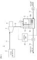
- FIG. 1 schematically shows an overall configuration of a power generation apparatus 1 according to the present invention.
- the power generation apparatus 1 is configured such that water vapor generated in a steam generator 2 is supplied to a scroll expander 3 so that the scroll expander 3 is driven to cause a generator 4 connected to the scroll expander 3 to generate electric power.
- a condensation device 5 is arranged in a discharge path 12 which is on the downstream side of the scroll expander 3.
- the condensation device 5 mixes the water vapor having passed through the scroll expander 3 directly with cooling water supplied from a cooling water supply path 13, thereby condensing the water vapor.
- the condensation device 5 includes a control unit 10 that controls the rotational frequency of a cooling water pump PI such that the amount of cooling water supply is so adjusted as to obtain condensed water having a predetermined temperature.
- the steam generator 2 is configured such that water vapor generated in the steam generator 2 is supplied to the scroll expander 3 through a water-vapor supply path 11.
- a water-vapor supply path 11 No particular limitation is put on the steam generator 2, and examples thereof may include: one using engine waste heat to convert water into water vapor; one using geothermal heat to generate water vapor; one using industrial waste heat to generate water vapor; and one using heat of an exhaust gas from an incinerator to generate water vapor.
- the scroll expander 3 is configured to be rotated by water vapor supplied through the supply path 11 at a rated rotational frequency of the scroll expander 3, which for example is 1800 to 3600 rpm, the scroll expander 3 being connectable directly with the generator 4.
- the generator 4 is not particularly limited as long as it is able to generate electric power by the direct connection with the scroll expander 3.
- Examples of the generator 4 include various types of generators such as induction generators and synchronous generators.
- An object to be driven by the scroll expander 3 is not limited to the generator 4, but may be a power output shaft for example.
- the condensation device 5 includes a container body 50 for preparing condensed water by mixing water vapor in the discharge path 12 which has passed through the scroll expander 3 with the cooling water supplied from the cooling water supply path 13.
- the container body 50 is provided with an introduction pipe 53 extending from the discharge path 12 into the container body 50.
- a distal end portion 53a of the introduction pipe 53 is located at a position near an interior bottom portion of the container body 50 such that water vapor discharged from the introduction pipe 53 is finely dispersed into bubbling in a liquid phase below a liquid level L of the cooling water introduced to the container body 50.
- the distal end portion 53a has a plurality of perforations formed throughout an outer peripheral surface thereof. This configuration allows the water vapor supplied from the introduction pipe 53 to be mixed while being finely dispersed into bubbling in the liquid phase of the cooling water within the container body 50. Thus, a shock caused at a time of mixing with the cooling water is reduced. Damage to the container body 50 can be prevented accordingly.
- a pressure fluctuation in the container body 50 is suppressed so that condensation pressure is stabilized, which leads to a stabilized electric power generation output. Moreover, generation of an abnormal noise during mixing can also be suppressed.
- the container body 50 is provided with the cooling water supply path 13.
- the cooling water supply path 13 has the cooling water pump PI.
- the control unit 10 controls the rotational frequency of the cooling water pump P1, thereby adjusting the amount of cooling water to be supplied into the container body 50.
- the container body 50 is connected with a condensed water supply path 14 that sends condensed water prepared in the container body 50 from the inside of the container body 50 to the outside.
- the condensed water supply path 14 has a condensed water pump P2.
- the control unit 10 controls the rotational frequency of the condensed water pump P2, thereby adjusting the amount of condensed water to be sent to the outside, the condensed water having its temperature adjusted in the container body 50.
- the container body 50 is provided with a temperature sensor T and a liquid level detection sensor S that detects the liquid level L in the container body 50.
- the liquid level detection sensor S includes a plurality of sensors (in this embodiment, three sensors) that are installed at different levels so as to enable detection of the liquid level L at different levels in the container body 50.
- the condensation device 5 is configured such that water vapor discharged from the discharge path 12 is mixed directly with the cooling water and thus condensed within the container body 50, thus preparing condensed water having a predetermined temperature. Preparation of the condensed water and sending of the condensed water to the outside are controlled by the control unit 10.
- the control unit 10 is configured to control the rotational frequency of the cooling water pump PI based on a result of detection of the condensed water temperature which is obtained from the temperature sensor T, thereby controlling the amount of cooling water to be supplied into the container body 50, thus preparing condensed water (for example, cold water or hot water) having a predetermined temperature.
- the control unit 10 is also configured to control the rotational frequency of the cooling water pump PI based on a result of detection of the condensed water temperature which is obtained from the temperature sensor T, thereby controlling the amount of cooling water to be supplied into the container body 50, thus controlling the condensation pressure in the container body 50 to be a predetermined condensation pressure.
- Such a control of the condensation pressure concurrently involves a control of condensation pressure on the outlet side of the scroll expander 3, and therefore the electric power generation output of the scroll expander 3 can be controlled.
- Whether to prioritize controlling the condensed water temperature or prioritize controlling the electric power generation output by the control unit 10 can be adjusted by appropriately changing setting of the control unit 10 in accordance with demands.
- the control unit 10 is configured to control the rotational frequency of the condensed water pump P2 based on a result of detection of the liquid level L which is obtained from the liquid level detection sensor S, thereby adjusting the amount of condensed water to be sent to the outside of the container body 50, thus maintaining the amount of liquid phase to such an extent that water vapor that is constantly discharged from the introduction pipe 53 into the container body 50 can bubble in the liquid phase.
- This control enables the control unit 10 to keep the water vapor and the cooling water in a successfully mixed state, and to maintain a safe operation of the condensation device 5.
- this embodiment is configured to suppress noises and pressure fluctuations by the condensation device 5 allowing the water vapor discharged from the introduction pipe 53 to be finely dispersed into bubbling in the liquid phase; such fine dispersion and bubbling may not be essential when the water vapor has a relatively low temperature or when an expander 3 less susceptible to condensation pressure is adopted.
- the distal end portion 53a of the introduction pipe 53 which has its cylindrical portion horizontally arranged with many perforations formed in an outer peripheral surface thereof, is configured to allow water vapor to be finely dispersed from the many perforations into bubbling.
- the shape of the distal end portion 53a is not particularly limited. For example, as shown in FIG.
- a spherical portion provided in the distal end portion 53a may have many perforations formed throughout an outer peripheral surface thereof such that water vapor be finely dispersed into bubbling in all directions in the liquid phase, or a diameter-expanded hemispherical portion provided in the distal end portion 53a may have many perforations formed in a spherical surface thereof such that water vapor be finely dispersed into bubbling in directions against the liquid level L of the liquid phase.
- FIG. 3 shows a power generation apparatus 1a according to another embodiment of the present invention.
- the same members as those of the power generation apparatus 1 shown in FIG. 1 are given the same reference signs, and descriptions thereof are omitted.
- the power generation apparatus 1a is identical to the above-described power generation apparatus 1 shown in FIG. 1 , except that an atmospheric air release path 15 having an atmospheric air release valve 6 is provided on an upper surface of the container body 50 of the condensation device 5.
- the water vapor and the cooling water are directly mixed so that a water vapor gas is condensed into a liquid, but a non-condensable gas which is a gas failing to be condensed into a liquid accumulates as time elapses.
- the accumulation of the non-condensable gas in the container body 50 makes it difficult for the control unit 10 to control the condensation pressure.
- a control unit 10 of the power generation apparatus 1a is configured to perform the following control at a time of start-up.
- the control unit 10 of the power generation apparatus 1a rotates the cooling water pump PI to charge the cooling water into the container body 50 through the cooling water supply path 13, and opens the atmospheric air release valve 6. By raising the liquid level L in the container body 50, the control unit 10 discharges the non-condensable gas accumulated in the container body 50 to the outside of the container body 50 through the atmospheric air release path 15.
- control unit 10 After discharging the non-condensable gas, the control unit 10 closes the atmospheric air release valve 6, and rotates the condensed water pump P2, to discharge the cooling water charged in the container body 50 to the outside until the liquid level L in the container body 50 reaches a predetermined level.
- the sequence of operations is performed based on a result of detection of the liquid level L which is obtained from the liquid level detection sensor S.
- control unit 10 stops the condensed water pump P2, and starts to supply water vapor from the steam generator 2 to the scroll expander 3, thus starting generation of electric power and preparation of condensed water. Then, as described above, the control unit 10 controls the condensed water temperature or controls the electric power generation output based on a result of detection of the condensed water temperature which is obtained from the temperature sensor T. At this time, whether to prioritize controlling the condensed water temperature or prioritize controlling the electric power generation output is adjusted by appropriately changing setting of the control unit 10 in accordance with demands.
- the power generation apparatus 1a which is able to discharge the non-condensable gas accumulated in the container body 50 to the outside without using a vacuum pump at a time of start-up, can simplify the apparatus configuration because no vacuum pump is used.
- the non-condensable gas is discharged to the outside of the container body 50, the condensation pressure during operation can be controlled well, so that the electric power generation output can be controlled comfortably.
- the power generation apparatus 1, 1a adopts the scroll expander 3.
- This expander may be a screw expander, a vane expander, a reciprocating expander, a swash plate expander, or the like.
- the power generation apparatus 1, 1a is configured such that the control unit 10 controls the rotational frequency of the cooling water pump P1, thereby controlling the amount of cooling water to be supplied from the cooling water supply path 13 into the container body 50.
- a flow control valve (not shown) may be adopted instead of the cooling water pump PI.
Landscapes
- Engineering & Computer Science (AREA)
- Mechanical Engineering (AREA)
- General Engineering & Computer Science (AREA)
- Chemical & Material Sciences (AREA)
- Combustion & Propulsion (AREA)
- Physics & Mathematics (AREA)
- Thermal Sciences (AREA)
- Life Sciences & Earth Sciences (AREA)
- Sustainable Development (AREA)
- Sustainable Energy (AREA)
- Engine Equipment That Uses Special Cycles (AREA)
- Control Of Turbines (AREA)
Abstract
Description
- The present invention relates to a power generation apparatus that utilizes water vapor.
- In a power plant facility using a diesel engine, generally, power equipment including a steam turbine in addition to the diesel engine is known, the steam turbine configured to generate electric power with use of a steam produced by waste heat of the diesel engine.
- Such power equipment including a steam turbine for generating electric power with use of a steam produced by waste heat conventionally includes: a steam turbine that recovers power from a produced steam; a generator that uses the power to generate electric power; a condenser that condenses the steam after the steam passes through the steam turbine; a condensation tank that stores drainage after the condensation; and a pump that sends water stored in the condensation tank.
- In a large-scale power equipment, such a power plant has been proposed that a turbine plant using, as an operating fluid, water vapor obtained by combusting hydrogen and oxygen directly introduces water to a condenser, to thereby raise the pressure of an exhaust gas in a path after passing through the turbine, thus lowering the compression ratio and obtaining hot water discharge (see PTL1, for example).
- PTL1: Japanese Patent Application Laid-Open No.
H7-158411 (1995 - In large-scale electric power generation in which water vapor obtained by combustion of hydrogen and oxygen is used as an operating fluid as in the conventional power plant mentioned above, a steam has a temperature of 1300°C or more, and therefore a primary purpose of directly introducing water to a condenser is to lower the compression ratio. Resulting hot water discharge, therefore, is a large amount of high-temperature water which is boiling at a temperature of 100°C or more, and it is impossible to manage, control, and adjust hot water discharge at a predetermined temperature.
- In small-scale power equipment using waste heat of a diesel engine, on the other hand, the compression ratio does not have to be taken into consideration because the temperature of the waste heat is not as high as in the large-scale electric power generation described above, but it is necessary to reduce costs by simplifying the configuration of the power equipment itself because the unit price per electricity output is higher than that of the large-scale power plant.
- The present invention has been made in view of the actual circumstances described above, and aims to provide a power generation apparatus for a small-scale power equipment that utilizes waste heat, the power generation apparatus having a simplified configuration in which a condenser is omitted so that water is directly introduced to a condensation tank, the power generation apparatus configured to manage and control the amount of water to be introduced so as to enable efficient supply of electricity and condensed water in accordance with demands.
- To solve the problems described above, a power generation apparatus according to the present invention is a power generation apparatus configured such that water vapor generated in a steam generator is supplied to an expander to drive the expander, wherein: a condensation device is arranged in a path downstream of the expander, the condensation device configured to mix water vapor having passed through the expander directly with cooling water to condense the water vapor; and the condensation device includes a control unit that performs a control of adjusting the amount of cooling water supply so as to obtain condensed water having a predetermined temperature.
- In the above power generation apparatus, the condensation device may be provided with means for detecting the height of a liquid level, and the control unit is configured to control, based on the height of the liquid level, the rotational frequency of a pump that sends a liquid out of the condensation device.
- In the above power generation apparatus, a water vapor introduction pipe extending from the path downstream of the expander may be introduced into the condensation device, and the introduction pipe may have a plurality of perforations formed in its portion below a predetermined water level such that bubbling occurs in a liquid phase below the predetermined water level in the condensation device.
- In the above power generation apparatus, an atmospheric air release path including an atmospheric air release valve may be connected to an upper portion of the condensation device.
- In the present invention, a condensation device arranged in a path downstream of an expander mixes water vapor having passed through the expander directly with cooling water to condense the water vapor, and the condensation device is provided with a control unit that performs a control of adjusting the flow rate of the cooling water so as to obtain condensed water having a predetermined temperature, which enables an electric power generation output to be changed by controlling condensation pressure. In addition, condensed water having a desired temperature can be supplied. Accordingly, electricity or condensed water can be supplied in accordance with demands with a simple configuration including no condenser.
-
- [
FIG. 1 ] A diagram schematically showing an overall configuration of a power generation apparatus according to the present invention. - [
FIG. 2 ] A diagram schematically showing another embodiment of a distal end portion of an introduction pipe of the power generation apparatus of the present invention. - [
FIG. 3 ] A diagram schematically showing an overall configuration of a power generation apparatus according to another embodiment of the present invention. - In the following, embodiments of the present invention will be described with reference to the drawings.
-
FIG. 1 schematically shows an overall configuration of apower generation apparatus 1 according to the present invention. - The
power generation apparatus 1 is configured such that water vapor generated in asteam generator 2 is supplied to a scroll expander 3 so that thescroll expander 3 is driven to cause agenerator 4 connected to the scroll expander 3 to generate electric power. Acondensation device 5 is arranged in adischarge path 12 which is on the downstream side of thescroll expander 3. Thecondensation device 5 mixes the water vapor having passed through the scroll expander 3 directly with cooling water supplied from a coolingwater supply path 13, thereby condensing the water vapor. Thecondensation device 5 includes acontrol unit 10 that controls the rotational frequency of a cooling water pump PI such that the amount of cooling water supply is so adjusted as to obtain condensed water having a predetermined temperature. - The
steam generator 2 is configured such that water vapor generated in thesteam generator 2 is supplied to the scroll expander 3 through a water-vapor supply path 11. No particular limitation is put on thesteam generator 2, and examples thereof may include: one using engine waste heat to convert water into water vapor; one using geothermal heat to generate water vapor; one using industrial waste heat to generate water vapor; and one using heat of an exhaust gas from an incinerator to generate water vapor. - The
scroll expander 3 is configured to be rotated by water vapor supplied through thesupply path 11 at a rated rotational frequency of thescroll expander 3, which for example is 1800 to 3600 rpm, the scroll expander 3 being connectable directly with thegenerator 4. - The
generator 4 is not particularly limited as long as it is able to generate electric power by the direct connection with thescroll expander 3. Examples of thegenerator 4 include various types of generators such as induction generators and synchronous generators. An object to be driven by thescroll expander 3 is not limited to thegenerator 4, but may be a power output shaft for example. - The
condensation device 5 includes acontainer body 50 for preparing condensed water by mixing water vapor in thedischarge path 12 which has passed through thescroll expander 3 with the cooling water supplied from the coolingwater supply path 13. - The
container body 50 is provided with anintroduction pipe 53 extending from thedischarge path 12 into thecontainer body 50. Adistal end portion 53a of theintroduction pipe 53 is located at a position near an interior bottom portion of thecontainer body 50 such that water vapor discharged from theintroduction pipe 53 is finely dispersed into bubbling in a liquid phase below a liquid level L of the cooling water introduced to thecontainer body 50. Thedistal end portion 53a has a plurality of perforations formed throughout an outer peripheral surface thereof. This configuration allows the water vapor supplied from theintroduction pipe 53 to be mixed while being finely dispersed into bubbling in the liquid phase of the cooling water within thecontainer body 50. Thus, a shock caused at a time of mixing with the cooling water is reduced. Damage to thecontainer body 50 can be prevented accordingly. In addition, a pressure fluctuation in thecontainer body 50 is suppressed so that condensation pressure is stabilized, which leads to a stabilized electric power generation output. Moreover, generation of an abnormal noise during mixing can also be suppressed. - The
container body 50 is provided with the coolingwater supply path 13. The coolingwater supply path 13 has the cooling water pump PI. Thecontrol unit 10 controls the rotational frequency of the cooling water pump P1, thereby adjusting the amount of cooling water to be supplied into thecontainer body 50. - The
container body 50 is connected with a condensedwater supply path 14 that sends condensed water prepared in thecontainer body 50 from the inside of thecontainer body 50 to the outside. The condensedwater supply path 14 has a condensed water pump P2. Thecontrol unit 10 controls the rotational frequency of the condensed water pump P2, thereby adjusting the amount of condensed water to be sent to the outside, the condensed water having its temperature adjusted in thecontainer body 50. - The
container body 50 is provided with a temperature sensor T and a liquid level detection sensor S that detects the liquid level L in thecontainer body 50. The liquid level detection sensor S includes a plurality of sensors (in this embodiment, three sensors) that are installed at different levels so as to enable detection of the liquid level L at different levels in thecontainer body 50. - The
condensation device 5 is configured such that water vapor discharged from thedischarge path 12 is mixed directly with the cooling water and thus condensed within thecontainer body 50, thus preparing condensed water having a predetermined temperature. Preparation of the condensed water and sending of the condensed water to the outside are controlled by thecontrol unit 10. - The
control unit 10 is configured to control the rotational frequency of the cooling water pump PI based on a result of detection of the condensed water temperature which is obtained from the temperature sensor T, thereby controlling the amount of cooling water to be supplied into thecontainer body 50, thus preparing condensed water (for example, cold water or hot water) having a predetermined temperature. Thecontrol unit 10 is also configured to control the rotational frequency of the cooling water pump PI based on a result of detection of the condensed water temperature which is obtained from the temperature sensor T, thereby controlling the amount of cooling water to be supplied into thecontainer body 50, thus controlling the condensation pressure in thecontainer body 50 to be a predetermined condensation pressure. Such a control of the condensation pressure concurrently involves a control of condensation pressure on the outlet side of the scroll expander 3, and therefore the electric power generation output of thescroll expander 3 can be controlled. Whether to prioritize controlling the condensed water temperature or prioritize controlling the electric power generation output by thecontrol unit 10 can be adjusted by appropriately changing setting of thecontrol unit 10 in accordance with demands. - The
control unit 10 is configured to control the rotational frequency of the condensed water pump P2 based on a result of detection of the liquid level L which is obtained from the liquid level detection sensor S, thereby adjusting the amount of condensed water to be sent to the outside of thecontainer body 50, thus maintaining the amount of liquid phase to such an extent that water vapor that is constantly discharged from theintroduction pipe 53 into thecontainer body 50 can bubble in the liquid phase. This control enables thecontrol unit 10 to keep the water vapor and the cooling water in a successfully mixed state, and to maintain a safe operation of thecondensation device 5. - Although this embodiment is configured to suppress noises and pressure fluctuations by the
condensation device 5 allowing the water vapor discharged from theintroduction pipe 53 to be finely dispersed into bubbling in the liquid phase; such fine dispersion and bubbling may not be essential when the water vapor has a relatively low temperature or when anexpander 3 less susceptible to condensation pressure is adopted. Thedistal end portion 53a of theintroduction pipe 53, which has its cylindrical portion horizontally arranged with many perforations formed in an outer peripheral surface thereof, is configured to allow water vapor to be finely dispersed from the many perforations into bubbling. Here, the shape of thedistal end portion 53a is not particularly limited. For example, as shown inFIG. 2 , a spherical portion provided in thedistal end portion 53a may have many perforations formed throughout an outer peripheral surface thereof such that water vapor be finely dispersed into bubbling in all directions in the liquid phase, or a diameter-expanded hemispherical portion provided in thedistal end portion 53a may have many perforations formed in a spherical surface thereof such that water vapor be finely dispersed into bubbling in directions against the liquid level L of the liquid phase. -
FIG. 3 shows a power generation apparatus 1a according to another embodiment of the present invention. InFIG. 3 , the same members as those of thepower generation apparatus 1 shown inFIG. 1 are given the same reference signs, and descriptions thereof are omitted. - The power generation apparatus 1a is identical to the above-described
power generation apparatus 1 shown inFIG. 1 , except that an atmosphericair release path 15 having an atmosphericair release valve 6 is provided on an upper surface of thecontainer body 50 of thecondensation device 5. - In the
container body 50, the water vapor and the cooling water are directly mixed so that a water vapor gas is condensed into a liquid, but a non-condensable gas which is a gas failing to be condensed into a liquid accumulates as time elapses. The accumulation of the non-condensable gas in thecontainer body 50 makes it difficult for thecontrol unit 10 to control the condensation pressure. - In this respect, a
control unit 10 of the power generation apparatus 1a according to the present invention is configured to perform the following control at a time of start-up. - The
control unit 10 of the power generation apparatus 1a, at a time of start-up, rotates the cooling water pump PI to charge the cooling water into thecontainer body 50 through the coolingwater supply path 13, and opens the atmosphericair release valve 6. By raising the liquid level L in thecontainer body 50, thecontrol unit 10 discharges the non-condensable gas accumulated in thecontainer body 50 to the outside of thecontainer body 50 through the atmosphericair release path 15. - After discharging the non-condensable gas, the
control unit 10 closes the atmosphericair release valve 6, and rotates the condensed water pump P2, to discharge the cooling water charged in thecontainer body 50 to the outside until the liquid level L in thecontainer body 50 reaches a predetermined level. The sequence of operations is performed based on a result of detection of the liquid level L which is obtained from the liquid level detection sensor S. - Then, the
control unit 10 stops the condensed water pump P2, and starts to supply water vapor from thesteam generator 2 to thescroll expander 3, thus starting generation of electric power and preparation of condensed water. Then, as described above, thecontrol unit 10 controls the condensed water temperature or controls the electric power generation output based on a result of detection of the condensed water temperature which is obtained from the temperature sensor T. At this time, whether to prioritize controlling the condensed water temperature or prioritize controlling the electric power generation output is adjusted by appropriately changing setting of thecontrol unit 10 in accordance with demands. - The power generation apparatus 1a, which is able to discharge the non-condensable gas accumulated in the
container body 50 to the outside without using a vacuum pump at a time of start-up, can simplify the apparatus configuration because no vacuum pump is used. In addition, since the non-condensable gas is discharged to the outside of thecontainer body 50, the condensation pressure during operation can be controlled well, so that the electric power generation output can be controlled comfortably. - In each of the embodiments described above, the
power generation apparatus 1, 1a adopts thescroll expander 3. This expander may be a screw expander, a vane expander, a reciprocating expander, a swash plate expander, or the like. - In each of the embodiments described above, the
power generation apparatus 1, 1a is configured such that thecontrol unit 10 controls the rotational frequency of the cooling water pump P1, thereby controlling the amount of cooling water to be supplied from the coolingwater supply path 13 into thecontainer body 50. Here, in a case where water pressure is already applied to the coolingwater supply path 13, a flow control valve (not shown) may be adopted instead of the cooling water pump PI. - It should be noted that the present invention may be embodied in many different forms without departing from the spirit or essential characteristics thereof. The above-described embodiments are therefore to be considered in all respects only as illustrative and not restrictive. The scope of the present invention is defined by the claims, and never bound by the description. All modifications and changes which come within the scope of the claims are to be embraced by the present invention.
-
- 1
- power generation apparatus
- 1a
- power generation apparatus
- 10
- control unit
- 11
- supply path
- 12
- discharge path
- 15
- atmospheric air release path
- 2
- steam generator
- 3
- scroll expander (expander)
- 4
- generator
- 5
- condensation device
- 53
- introduction pipe
- 6
- atmospheric air release valve
- L
- liquid level
- S
- liquid level detection sensor
- P
- cooling water pump
Claims (5)
- A power generation apparatus configured such that water vapor generated in a steam generator is supplied to an expander to drive the expander, wherein
a condensation device is arranged in a path downstream of the expander, the condensation device configured to mix water vapor having passed through the expander directly with cooling water to condense the water vapor, and
the condensation device includes a control unit that performs a control of adjusting the amount of cooling water supply so as to obtain condensed water having a predetermined temperature. - The power generation apparatus according to claim 1, wherein the condensation device is provided with means for detecting the height of a liquid level, and the control unit is configured to control, based on the height of the liquid level, the rotational frequency of a pump that sends a liquid out of the condensation device.
- The power generation apparatus according to claim 1 or 2, wherein a water vapor introduction pipe extending from the path downstream of the expander is introduced into the condensation device, and the introduction pipe has a plurality of perforations formed in its portion below a predetermined water level such that bubbling occurs in a liquid phase below the predetermined water level in the condensation device.
- The power generation apparatus according to claim 1 or 2, wherein an atmospheric air release path including an atmospheric air release valve is connected to an upper portion of the condensation device.
- The power generation apparatus according to claim 3, wherein an atmospheric air release path including an atmospheric air release valve is connected to an upper portion of the condensation device.
Applications Claiming Priority (2)
| Application Number | Priority Date | Filing Date | Title |
|---|---|---|---|
| JP2015044343A JP6254968B2 (en) | 2015-03-06 | 2015-03-06 | Power generator |
| PCT/JP2016/055861 WO2016143558A1 (en) | 2015-03-06 | 2016-02-26 | Power generation apparatus |
Publications (3)
| Publication Number | Publication Date |
|---|---|
| EP3266996A1 true EP3266996A1 (en) | 2018-01-10 |
| EP3266996A4 EP3266996A4 (en) | 2018-04-18 |
| EP3266996B1 EP3266996B1 (en) | 2021-11-17 |
Family
ID=56876706
Family Applications (1)
| Application Number | Title | Priority Date | Filing Date |
|---|---|---|---|
| EP16761529.3A Not-in-force EP3266996B1 (en) | 2015-03-06 | 2016-02-26 | Power generation apparatus |
Country Status (5)
| Country | Link |
|---|---|
| US (1) | US10519813B2 (en) |
| EP (1) | EP3266996B1 (en) |
| JP (1) | JP6254968B2 (en) |
| KR (1) | KR101982957B1 (en) |
| WO (1) | WO2016143558A1 (en) |
Cited By (1)
| Publication number | Priority date | Publication date | Assignee | Title |
|---|---|---|---|---|
| CN111076566A (en) * | 2019-12-27 | 2020-04-28 | 攀钢集团西昌钢钒有限公司 | a hot water generator |
Families Citing this family (3)
| Publication number | Priority date | Publication date | Assignee | Title |
|---|---|---|---|---|
| DE102018221728B4 (en) * | 2018-12-14 | 2022-10-27 | Contitech Mgw Gmbh | Condensation device for process steam from a process steam source |
| JP7147641B2 (en) * | 2019-03-18 | 2022-10-05 | いすゞ自動車株式会社 | Rankine cycle system and its control method |
| US20240392699A1 (en) * | 2023-05-24 | 2024-11-28 | Raytheon Technologies Corporation | Condenser for steam-injected engine |
Family Cites Families (31)
| Publication number | Priority date | Publication date | Assignee | Title |
|---|---|---|---|---|
| US3277955A (en) * | 1961-11-01 | 1966-10-11 | Heller Laszlo | Control apparatus for air-cooled steam condensation systems |
| DE1925234B2 (en) * | 1969-05-17 | 1973-08-16 | GEA Luftkuhlergesellschaft Happel GmbH & Co KG, 4630 Bochum | INJECTION CONDENSATION SYSTEM WITH RECOOLING OF THE INJECTION WATER VIA AIR-COOLED COOLING ELEMENTS |
| HU164245B (en) | 1971-08-03 | 1974-01-28 | ||
| US3965675A (en) * | 1974-08-08 | 1976-06-29 | Westinghouse Electric Corporation | Combined cycle electric power plant and a heat recovery steam generator having improved boiler feed pump flow control |
| JPS5162205A (en) * | 1974-11-28 | 1976-05-29 | Tokyo Shibaura Electric Co | Haikikanniokeru hanmaringuboshisochi |
| CH635184A5 (en) * | 1978-12-22 | 1983-03-15 | Sulzer Ag | STEAM GENERATOR SYSTEM. |
| JPS55116010A (en) * | 1979-02-27 | 1980-09-06 | Hitachi Ltd | Method of controlling water level of steam condensation system |
| JPS5630583A (en) * | 1979-08-21 | 1981-03-27 | Hitachi Ltd | Operation of side stream type condensation system and apparatus for flushing device in side stream type condensation system |
| US4506508A (en) | 1983-03-25 | 1985-03-26 | Chicago Bridge & Iron Company | Apparatus and method for condensing steam |
| JPS61215407A (en) * | 1985-03-20 | 1986-09-25 | Hitachi Ltd | Combined plant condenser water level control method |
| US4622820A (en) * | 1985-09-27 | 1986-11-18 | Sundquist Charles T | Absorption power generator |
| US4873829A (en) * | 1988-08-29 | 1989-10-17 | Williamson Anthony R | Steam power plant |
| US5005351A (en) * | 1990-02-26 | 1991-04-09 | Westinghouse Electric Corp. | Power plant condenser control system |
| JPH04140404A (en) * | 1990-09-29 | 1992-05-14 | Fuji Electric Co Ltd | Excessive steam heat recovering facility for boiler |
| JP3161072B2 (en) * | 1992-09-10 | 2001-04-25 | 株式会社日立製作所 | Condenser and its operation method, and condenser system and its operation method |
| JPH07158411A (en) | 1993-12-06 | 1995-06-20 | Hitachi Ltd | Power plant |
| US5925291A (en) * | 1997-03-25 | 1999-07-20 | Midwest Research Institute | Method and apparatus for high-efficiency direct contact condensation |
| JPH1136818A (en) * | 1997-07-18 | 1999-02-09 | Toshiba Corp | Control system for waste heat combined cycle power plant |
| US6484503B1 (en) * | 2000-01-12 | 2002-11-26 | Arie Raz | Compression and condensation of turbine exhaust steam |
| US7065970B2 (en) * | 2003-11-07 | 2006-06-27 | Harpster Joseph W C | Condensers and their monitoring |
| JP5159257B2 (en) * | 2007-11-06 | 2013-03-06 | 中国電力株式会社 | Condenser vacuum break valve seal structure and power generation equipment |
| US7735323B2 (en) * | 2008-02-12 | 2010-06-15 | Lawrence Livermore National Security, Llc | Solar thermal power system |
| DE102008008637B4 (en) * | 2008-02-12 | 2017-01-05 | Man Diesel & Turbo Se | Condensing steam turbine with level detection device and method for controlling the level |
| JP4982507B2 (en) * | 2009-01-09 | 2012-07-25 | 株式会社日立製作所 | Turbine ground seal steam temperature reduction control device and plant control method in steam turbine power generation facility |
| HU228665B1 (en) | 2009-12-03 | 2013-05-28 | Gea Egi Energiagazdalkodasi Zrt | Hybrid cooling system |
| JP2013531178A (en) * | 2010-07-14 | 2013-08-01 | ジ アベル ファウンデーション, インコーポレイテッド | Industrial ocean thermal energy conversion process |
| US9512741B2 (en) * | 2011-08-19 | 2016-12-06 | Fuji Electric Co., Ltd. | Power plant |
| US10343115B2 (en) * | 2013-01-22 | 2019-07-09 | Steen Research, Llc | Methods and equipment for treatment of odorous gas steams |
| US9328964B2 (en) * | 2013-02-01 | 2016-05-03 | Dell Products, L.P. | Partitioned, rotating condenser units to enable servicing of submerged it equipment positioned beneath a vapor condenser without interrupting a vaporization-condensation cycling of the remaining immersion cooling system |
| JP2015050778A (en) | 2013-08-29 | 2015-03-16 | ヤンマー株式会社 | Operation method of power generator |
| US10670340B2 (en) * | 2014-12-01 | 2020-06-02 | Ormat Technologies, Inc. | Cooling water supply system and method |
-
2015
- 2015-03-06 JP JP2015044343A patent/JP6254968B2/en not_active Expired - Fee Related
-
2016
- 2016-02-26 EP EP16761529.3A patent/EP3266996B1/en not_active Not-in-force
- 2016-02-26 WO PCT/JP2016/055861 patent/WO2016143558A1/en not_active Ceased
- 2016-02-26 US US15/555,946 patent/US10519813B2/en not_active Expired - Fee Related
- 2016-02-26 KR KR1020177023998A patent/KR101982957B1/en not_active Expired - Fee Related
Cited By (1)
| Publication number | Priority date | Publication date | Assignee | Title |
|---|---|---|---|---|
| CN111076566A (en) * | 2019-12-27 | 2020-04-28 | 攀钢集团西昌钢钒有限公司 | a hot water generator |
Also Published As
| Publication number | Publication date |
|---|---|
| US10519813B2 (en) | 2019-12-31 |
| KR20170105625A (en) | 2017-09-19 |
| EP3266996A4 (en) | 2018-04-18 |
| KR101982957B1 (en) | 2019-05-27 |
| JP2016164380A (en) | 2016-09-08 |
| WO2016143558A1 (en) | 2016-09-15 |
| US20180051595A1 (en) | 2018-02-22 |
| EP3266996B1 (en) | 2021-11-17 |
| JP6254968B2 (en) | 2017-12-27 |
Similar Documents
| Publication | Publication Date | Title |
|---|---|---|
| US10519813B2 (en) | Power generation apparatus | |
| JP4787199B2 (en) | Steam recovery equipment | |
| JP4997333B2 (en) | Method and apparatus for starting a refrigerant system without preheating oil | |
| EP2540995B1 (en) | Power generation apparatus | |
| JP2007503546A (en) | Energy recovery system | |
| CN106030052B (en) | Combined-circulation equipment, its control method and its control device | |
| WO2015054834A1 (en) | Gas turbine system and method of operation | |
| EP3037631A1 (en) | Thermal electric power generator | |
| JPWO2009040919A1 (en) | Sludge drying system | |
| CN107614837B (en) | Combined cycle plant, control device and starting method thereof | |
| BR102013007109A2 (en) | Gas turbine starter with frequency converter | |
| CN102066694B (en) | Operation of a gas and steam turbine system, and gas and steam turbine system | |
| JP4990008B2 (en) | Steam treatment equipment | |
| CN204923937U (en) | Power plant condenser vacuum improves device and thermal power system | |
| JP6277148B2 (en) | Power generator | |
| JP2015050778A (en) | Operation method of power generator | |
| JP4133355B2 (en) | Steam power generator | |
| JP3219186U (en) | Solar air power generation equipment | |
| CN219036590U (en) | Waste heat recovery system of coal-fired power plant | |
| JP4198475B2 (en) | Steam power generator | |
| CN207740050U (en) | A kind of saturated vapor turbine set for gas ventilation air methane oxidation electricity generation system | |
| JP2009052489A (en) | Steam system | |
| CN116951395A (en) | System for optimally utilizing blowdown steam of coal-fired thermal power plant and operation method | |
| KR101644547B1 (en) | Power generation plant including auxiliary power generation system | |
| EP2143892A1 (en) | Steam turbine operation control device |
Legal Events
| Date | Code | Title | Description |
|---|---|---|---|
| STAA | Information on the status of an ep patent application or granted ep patent |
Free format text: STATUS: THE INTERNATIONAL PUBLICATION HAS BEEN MADE |
|
| PUAI | Public reference made under article 153(3) epc to a published international application that has entered the european phase |
Free format text: ORIGINAL CODE: 0009012 |
|
| STAA | Information on the status of an ep patent application or granted ep patent |
Free format text: STATUS: REQUEST FOR EXAMINATION WAS MADE |
|
| 17P | Request for examination filed |
Effective date: 20170816 |
|
| AK | Designated contracting states |
Kind code of ref document: A1 Designated state(s): AL AT BE BG CH CY CZ DE DK EE ES FI FR GB GR HR HU IE IS IT LI LT LU LV MC MK MT NL NO PL PT RO RS SE SI SK SM TR |
|
| AX | Request for extension of the european patent |
Extension state: BA ME |
|
| A4 | Supplementary search report drawn up and despatched |
Effective date: 20180316 |
|
| RIC1 | Information provided on ipc code assigned before grant |
Ipc: F01K 9/00 20060101AFI20180312BHEP Ipc: F01K 9/02 20060101ALI20180312BHEP Ipc: F28B 3/06 20060101ALI20180312BHEP Ipc: F22B 3/06 20060101ALI20180312BHEP Ipc: F22B 1/18 20060101ALI20180312BHEP Ipc: F22B 3/04 20060101ALI20180312BHEP |
|
| DAV | Request for validation of the european patent (deleted) | ||
| DAX | Request for extension of the european patent (deleted) | ||
| RAP1 | Party data changed (applicant data changed or rights of an application transferred) |
Owner name: YANMAR POWER TECHNOLOGY CO., LTD. |
|
| GRAP | Despatch of communication of intention to grant a patent |
Free format text: ORIGINAL CODE: EPIDOSNIGR1 |
|
| STAA | Information on the status of an ep patent application or granted ep patent |
Free format text: STATUS: GRANT OF PATENT IS INTENDED |
|
| INTG | Intention to grant announced |
Effective date: 20210616 |
|
| GRAS | Grant fee paid |
Free format text: ORIGINAL CODE: EPIDOSNIGR3 |
|
| GRAA | (expected) grant |
Free format text: ORIGINAL CODE: 0009210 |
|
| STAA | Information on the status of an ep patent application or granted ep patent |
Free format text: STATUS: THE PATENT HAS BEEN GRANTED |
|
| AK | Designated contracting states |
Kind code of ref document: B1 Designated state(s): AL AT BE BG CH CY CZ DE DK EE ES FI FR GB GR HR HU IE IS IT LI LT LU LV MC MK MT NL NO PL PT RO RS SE SI SK SM TR |
|
| REG | Reference to a national code |
Ref country code: GB Ref legal event code: FG4D |
|
| REG | Reference to a national code |
Ref country code: IE Ref legal event code: FG4D |
|
| REG | Reference to a national code |
Ref country code: DE Ref legal event code: R096 Ref document number: 602016066346 Country of ref document: DE |
|
| REG | Reference to a national code |
Ref country code: AT Ref legal event code: REF Ref document number: 1448222 Country of ref document: AT Kind code of ref document: T Effective date: 20211215 |
|
| REG | Reference to a national code |
Ref country code: LT Ref legal event code: MG9D |
|
| REG | Reference to a national code |
Ref country code: NL Ref legal event code: MP Effective date: 20211117 |
|
| REG | Reference to a national code |
Ref country code: AT Ref legal event code: MK05 Ref document number: 1448222 Country of ref document: AT Kind code of ref document: T Effective date: 20211117 |
|
| PG25 | Lapsed in a contracting state [announced via postgrant information from national office to epo] |
Ref country code: RS Free format text: LAPSE BECAUSE OF FAILURE TO SUBMIT A TRANSLATION OF THE DESCRIPTION OR TO PAY THE FEE WITHIN THE PRESCRIBED TIME-LIMIT Effective date: 20211117 Ref country code: LT Free format text: LAPSE BECAUSE OF FAILURE TO SUBMIT A TRANSLATION OF THE DESCRIPTION OR TO PAY THE FEE WITHIN THE PRESCRIBED TIME-LIMIT Effective date: 20211117 Ref country code: FI Free format text: LAPSE BECAUSE OF FAILURE TO SUBMIT A TRANSLATION OF THE DESCRIPTION OR TO PAY THE FEE WITHIN THE PRESCRIBED TIME-LIMIT Effective date: 20211117 Ref country code: BG Free format text: LAPSE BECAUSE OF FAILURE TO SUBMIT A TRANSLATION OF THE DESCRIPTION OR TO PAY THE FEE WITHIN THE PRESCRIBED TIME-LIMIT Effective date: 20220217 Ref country code: AT Free format text: LAPSE BECAUSE OF FAILURE TO SUBMIT A TRANSLATION OF THE DESCRIPTION OR TO PAY THE FEE WITHIN THE PRESCRIBED TIME-LIMIT Effective date: 20211117 |
|
| PGFP | Annual fee paid to national office [announced via postgrant information from national office to epo] |
Ref country code: DE Payment date: 20220217 Year of fee payment: 7 |
|
| PG25 | Lapsed in a contracting state [announced via postgrant information from national office to epo] |
Ref country code: IS Free format text: LAPSE BECAUSE OF FAILURE TO SUBMIT A TRANSLATION OF THE DESCRIPTION OR TO PAY THE FEE WITHIN THE PRESCRIBED TIME-LIMIT Effective date: 20220317 Ref country code: SE Free format text: LAPSE BECAUSE OF FAILURE TO SUBMIT A TRANSLATION OF THE DESCRIPTION OR TO PAY THE FEE WITHIN THE PRESCRIBED TIME-LIMIT Effective date: 20211117 Ref country code: PT Free format text: LAPSE BECAUSE OF FAILURE TO SUBMIT A TRANSLATION OF THE DESCRIPTION OR TO PAY THE FEE WITHIN THE PRESCRIBED TIME-LIMIT Effective date: 20220317 Ref country code: PL Free format text: LAPSE BECAUSE OF FAILURE TO SUBMIT A TRANSLATION OF THE DESCRIPTION OR TO PAY THE FEE WITHIN THE PRESCRIBED TIME-LIMIT Effective date: 20211117 Ref country code: NO Free format text: LAPSE BECAUSE OF FAILURE TO SUBMIT A TRANSLATION OF THE DESCRIPTION OR TO PAY THE FEE WITHIN THE PRESCRIBED TIME-LIMIT Effective date: 20220217 Ref country code: NL Free format text: LAPSE BECAUSE OF FAILURE TO SUBMIT A TRANSLATION OF THE DESCRIPTION OR TO PAY THE FEE WITHIN THE PRESCRIBED TIME-LIMIT Effective date: 20211117 Ref country code: LV Free format text: LAPSE BECAUSE OF FAILURE TO SUBMIT A TRANSLATION OF THE DESCRIPTION OR TO PAY THE FEE WITHIN THE PRESCRIBED TIME-LIMIT Effective date: 20211117 Ref country code: HR Free format text: LAPSE BECAUSE OF FAILURE TO SUBMIT A TRANSLATION OF THE DESCRIPTION OR TO PAY THE FEE WITHIN THE PRESCRIBED TIME-LIMIT Effective date: 20211117 Ref country code: GR Free format text: LAPSE BECAUSE OF FAILURE TO SUBMIT A TRANSLATION OF THE DESCRIPTION OR TO PAY THE FEE WITHIN THE PRESCRIBED TIME-LIMIT Effective date: 20220218 Ref country code: ES Free format text: LAPSE BECAUSE OF FAILURE TO SUBMIT A TRANSLATION OF THE DESCRIPTION OR TO PAY THE FEE WITHIN THE PRESCRIBED TIME-LIMIT Effective date: 20211117 |
|
| PGFP | Annual fee paid to national office [announced via postgrant information from national office to epo] |
Ref country code: IT Payment date: 20220228 Year of fee payment: 7 |
|
| PG25 | Lapsed in a contracting state [announced via postgrant information from national office to epo] |
Ref country code: SM Free format text: LAPSE BECAUSE OF FAILURE TO SUBMIT A TRANSLATION OF THE DESCRIPTION OR TO PAY THE FEE WITHIN THE PRESCRIBED TIME-LIMIT Effective date: 20211117 Ref country code: SK Free format text: LAPSE BECAUSE OF FAILURE TO SUBMIT A TRANSLATION OF THE DESCRIPTION OR TO PAY THE FEE WITHIN THE PRESCRIBED TIME-LIMIT Effective date: 20211117 Ref country code: RO Free format text: LAPSE BECAUSE OF FAILURE TO SUBMIT A TRANSLATION OF THE DESCRIPTION OR TO PAY THE FEE WITHIN THE PRESCRIBED TIME-LIMIT Effective date: 20211117 Ref country code: EE Free format text: LAPSE BECAUSE OF FAILURE TO SUBMIT A TRANSLATION OF THE DESCRIPTION OR TO PAY THE FEE WITHIN THE PRESCRIBED TIME-LIMIT Effective date: 20211117 Ref country code: DK Free format text: LAPSE BECAUSE OF FAILURE TO SUBMIT A TRANSLATION OF THE DESCRIPTION OR TO PAY THE FEE WITHIN THE PRESCRIBED TIME-LIMIT Effective date: 20211117 Ref country code: CZ Free format text: LAPSE BECAUSE OF FAILURE TO SUBMIT A TRANSLATION OF THE DESCRIPTION OR TO PAY THE FEE WITHIN THE PRESCRIBED TIME-LIMIT Effective date: 20211117 |
|
| REG | Reference to a national code |
Ref country code: DE Ref legal event code: R097 Ref document number: 602016066346 Country of ref document: DE |
|
| PLBE | No opposition filed within time limit |
Free format text: ORIGINAL CODE: 0009261 |
|
| STAA | Information on the status of an ep patent application or granted ep patent |
Free format text: STATUS: NO OPPOSITION FILED WITHIN TIME LIMIT |
|
| PG25 | Lapsed in a contracting state [announced via postgrant information from national office to epo] |
Ref country code: MC Free format text: LAPSE BECAUSE OF FAILURE TO SUBMIT A TRANSLATION OF THE DESCRIPTION OR TO PAY THE FEE WITHIN THE PRESCRIBED TIME-LIMIT Effective date: 20211117 |
|
| REG | Reference to a national code |
Ref country code: CH Ref legal event code: PL |
|
| REG | Reference to a national code |
Ref country code: BE Ref legal event code: MM Effective date: 20220228 |
|
| 26N | No opposition filed |
Effective date: 20220818 |
|
| GBPC | Gb: european patent ceased through non-payment of renewal fee |
Effective date: 20220226 |
|
| PG25 | Lapsed in a contracting state [announced via postgrant information from national office to epo] |
Ref country code: LU Free format text: LAPSE BECAUSE OF NON-PAYMENT OF DUE FEES Effective date: 20220226 Ref country code: AL Free format text: LAPSE BECAUSE OF FAILURE TO SUBMIT A TRANSLATION OF THE DESCRIPTION OR TO PAY THE FEE WITHIN THE PRESCRIBED TIME-LIMIT Effective date: 20211117 |
|
| PG25 | Lapsed in a contracting state [announced via postgrant information from national office to epo] |
Ref country code: SI Free format text: LAPSE BECAUSE OF FAILURE TO SUBMIT A TRANSLATION OF THE DESCRIPTION OR TO PAY THE FEE WITHIN THE PRESCRIBED TIME-LIMIT Effective date: 20211117 |
|
| PG25 | Lapsed in a contracting state [announced via postgrant information from national office to epo] |
Ref country code: FR Free format text: LAPSE BECAUSE OF NON-PAYMENT OF DUE FEES Effective date: 20220228 |
|
| PG25 | Lapsed in a contracting state [announced via postgrant information from national office to epo] |
Ref country code: LI Free format text: LAPSE BECAUSE OF NON-PAYMENT OF DUE FEES Effective date: 20220228 Ref country code: IE Free format text: LAPSE BECAUSE OF NON-PAYMENT OF DUE FEES Effective date: 20220226 Ref country code: GB Free format text: LAPSE BECAUSE OF NON-PAYMENT OF DUE FEES Effective date: 20220226 Ref country code: CH Free format text: LAPSE BECAUSE OF NON-PAYMENT OF DUE FEES Effective date: 20220228 |
|
| PG25 | Lapsed in a contracting state [announced via postgrant information from national office to epo] |
Ref country code: BE Free format text: LAPSE BECAUSE OF NON-PAYMENT OF DUE FEES Effective date: 20220228 |
|
| REG | Reference to a national code |
Ref country code: DE Ref legal event code: R119 Ref document number: 602016066346 Country of ref document: DE |
|
| PG25 | Lapsed in a contracting state [announced via postgrant information from national office to epo] |
Ref country code: IT Free format text: LAPSE BECAUSE OF NON-PAYMENT OF DUE FEES Effective date: 20230226 Ref country code: DE Free format text: LAPSE BECAUSE OF NON-PAYMENT OF DUE FEES Effective date: 20230901 |
|
| PG25 | Lapsed in a contracting state [announced via postgrant information from national office to epo] |
Ref country code: HU Free format text: LAPSE BECAUSE OF FAILURE TO SUBMIT A TRANSLATION OF THE DESCRIPTION OR TO PAY THE FEE WITHIN THE PRESCRIBED TIME-LIMIT; INVALID AB INITIO Effective date: 20160226 |
|
| PG25 | Lapsed in a contracting state [announced via postgrant information from national office to epo] |
Ref country code: MK Free format text: LAPSE BECAUSE OF FAILURE TO SUBMIT A TRANSLATION OF THE DESCRIPTION OR TO PAY THE FEE WITHIN THE PRESCRIBED TIME-LIMIT Effective date: 20211117 Ref country code: CY Free format text: LAPSE BECAUSE OF FAILURE TO SUBMIT A TRANSLATION OF THE DESCRIPTION OR TO PAY THE FEE WITHIN THE PRESCRIBED TIME-LIMIT Effective date: 20211117 |
|
| PG25 | Lapsed in a contracting state [announced via postgrant information from national office to epo] |
Ref country code: MT Free format text: LAPSE BECAUSE OF FAILURE TO SUBMIT A TRANSLATION OF THE DESCRIPTION OR TO PAY THE FEE WITHIN THE PRESCRIBED TIME-LIMIT Effective date: 20211117 |
|
| PG25 | Lapsed in a contracting state [announced via postgrant information from national office to epo] |
Ref country code: TR Free format text: LAPSE BECAUSE OF FAILURE TO SUBMIT A TRANSLATION OF THE DESCRIPTION OR TO PAY THE FEE WITHIN THE PRESCRIBED TIME-LIMIT Effective date: 20211117 |