EP3266936A1 - Protective visual and wind barrier - Google Patents
Protective visual and wind barrier Download PDFInfo
- Publication number
- EP3266936A1 EP3266936A1 EP17001145.6A EP17001145A EP3266936A1 EP 3266936 A1 EP3266936 A1 EP 3266936A1 EP 17001145 A EP17001145 A EP 17001145A EP 3266936 A1 EP3266936 A1 EP 3266936A1
- Authority
- EP
- European Patent Office
- Prior art keywords
- wind
- barrier
- row
- visual
- posts
- Prior art date
- Legal status (The legal status is an assumption and is not a legal conclusion. Google has not performed a legal analysis and makes no representation as to the accuracy of the status listed.)
- Granted
Links
Images



Classifications
-
- E—FIXED CONSTRUCTIONS
- E01—CONSTRUCTION OF ROADS, RAILWAYS, OR BRIDGES
- E01F—ADDITIONAL WORK, SUCH AS EQUIPPING ROADS OR THE CONSTRUCTION OF PLATFORMS, HELICOPTER LANDING STAGES, SIGNS, SNOW FENCES, OR THE LIKE
- E01F7/00—Devices affording protection against snow, sand drifts, side-wind effects, snowslides, avalanches or falling rocks; Anti-dazzle arrangements ; Sight-screens for roads, e.g. to mask accident site
- E01F7/02—Snow fences or similar devices, e.g. devices affording protection against sand drifts or side-wind effects
- E01F7/025—Devices specially adapted for protecting against wind, e.g. screens, deflectors or attenuators at tunnel or lock entrances
Definitions
- the object of the present invention relates to a protective visual and wind barrier, having an obvious advantage over those barriers already known, which advantage will be described below.
- the present invention is based on conventional systems that have been used since ancient times, said systems being both natural and artificial systems for protection against the wind, such as palisade fencing, hedges, open worked walls, or even fabric or perforated barriers. They all have drawbacks. Take, for example, the case of fabrics. If the openings in the mesh are closed up, the area of protection is drastically reduced, in turn generating turbulences that force the lower layers of air up to higher altitudes.
- Having a permeability of greater than or less than 50% in simple, thin barriers does not increase the area they protect, but quite the contrary; they reduce this area as turbulences are generated immediately on the other side of the protective element in the case of having a lower permeability and at high wind speeds with barriers having a higher permeability.
- the area this barrier is supposed to protect is reduced to half (from twenty times the height of the barrier to just ten times the height), turbulences increasing on the other side thereof.
- barriers require continuous maintenance and have the purpose of obtaining a low permeability that involves trapping a large number of particles entrained by the air that are falling to the ground.
- An effective barrier for generating a relatively calm area requires a permeability of 50%, whereas a barrier that effectively traps the particles requires a very low permeability, so the same type of fabric barrier will not serve for both wind-trapping and particle-trapping functions.
- a protective visual and wind barrier made up of precast reinforced concrete elements has been designed, eliminating all the drawbacks of the previous barriers and having a rapid and economic construction.
- the system on which it is based has been subjected to a number of aerodynamic tests conducted in a wind tunnel, assuring a very high efficacy as a wind speed reducing element, and more importantly, it is able to generate a very large area of protection that is independent of the saturation of the element. Saturation thereof is impossible because it has a high net permeability, even though the gross permeability is very low as a result of the dual arrangement of the elements, thereby extending the protective effect and minimizing turbulences in the protected area.
- the protective visual and wind barrier of the present invention consists of precast reinforced concrete posts separated from one another a variable distance and arranged in one, two or more lines, thereby generating both a visual barrier and a very effective protection against the wind.
- the final effect of the barrier will depend on the angulation, separation between posts and size thereof, such that by modifying the separation between posts, their angle in relation to the wind, the separation between lines, the height and section of the posts, a wide range of wind reductions can be configured as needed.
- precast concrete can be a removable and therefore temporary system, or it can be permanent.
- precast concrete also allows for a wide range of possibilities in terms of textures and colors without altering its durability and efficacy, so many images can be created when this system is also used as a visual barrier. It can be placed on an existing surface, anchoring it to same by means of chemical or mechanical systems, or it can be provided along with its own foundation, which is also precast, which meets and adapts to the requirements and stresses to which said barrier will be subjected.
- This barrier has a permeability per line of 55% and a combined permeability of 10%, so it has an efficacy proven in earlier tests as regards wind reduction. In terms of the capacity to trap dust, this system works in two ways. On one hand, the combined permeability of the system is 10% and this means that only 10% of the air that goes through it will not hit the protective elements, making the particles fall to the ground.
- the protective visual and wind barrier of the present invention consists of precast reinforced concrete posts (1), separated from one another a variable distance and arranged in one, two or more lines or rows, generating both a visual barrier and a very effective protection against the wind, such that when the air strikes the first posts (1) it is split up into several gusts which are split up again into more gusts when they hit the second row (2) and so on and so forth when they hit the third row (not depicted herein), contemplating the possibility of a fourth row, a fifth row, etc., as needed, thereby generating a very significant reduction of the wind speed, creating a relatively calm atmosphere on the other side of the barrier.
Landscapes
- Engineering & Computer Science (AREA)
- Architecture (AREA)
- Civil Engineering (AREA)
- Structural Engineering (AREA)
- Devices Affording Protection Of Roads Or Walls For Sound Insulation (AREA)
- Buildings Adapted To Withstand Abnormal External Influences (AREA)
- Aerodynamic Tests, Hydrodynamic Tests, Wind Tunnels, And Water Tanks (AREA)
Abstract
Description
- As indicated by the title, the object of the present invention relates to a protective visual and wind barrier, having an obvious advantage over those barriers already known, which advantage will be described below.
- The present invention is based on conventional systems that have been used since ancient times, said systems being both natural and artificial systems for protection against the wind, such as palisade fencing, hedges, open worked walls, or even fabric or perforated barriers. They all have drawbacks. Take, for example, the case of fabrics. If the openings in the mesh are closed up, the area of protection is drastically reduced, in turn generating turbulences that force the lower layers of air up to higher altitudes. Having a permeability of greater than or less than 50% in simple, thin barriers (for example fabric or metal barriers) does not increase the area they protect, but quite the contrary; they reduce this area as turbulences are generated immediately on the other side of the protective element in the case of having a lower permeability and at high wind speeds with barriers having a higher permeability. Compounding that with the real possibility of the protective fabrics becoming clogged up (accumulation of sediments), the area this barrier is supposed to protect is reduced to half (from twenty times the height of the barrier to just ten times the height), turbulences increasing on the other side thereof. These barriers require continuous maintenance and have the purpose of obtaining a low permeability that involves trapping a large number of particles entrained by the air that are falling to the ground. An effective barrier for generating a relatively calm area requires a permeability of 50%, whereas a barrier that effectively traps the particles requires a very low permeability, so the same type of fabric barrier will not serve for both wind-trapping and particle-trapping functions.
- To solve these drawbacks, a protective visual and wind barrier made up of precast reinforced concrete elements has been designed, eliminating all the drawbacks of the previous barriers and having a rapid and economic construction. The system on which it is based has been subjected to a number of aerodynamic tests conducted in a wind tunnel, assuring a very high efficacy as a wind speed reducing element, and more importantly, it is able to generate a very large area of protection that is independent of the saturation of the element. Saturation thereof is impossible because it has a high net permeability, even though the gross permeability is very low as a result of the dual arrangement of the elements, thereby extending the protective effect and minimizing turbulences in the protected area. These advantages along with its capacity of being indefinitely maintained over time, retaining its protective capabilities, zero maintenance and simple and long-lasting appearance, makes it the only solution for aggressive environments and for environments with very high wind speeds, having a low installation time and cost.
- The features of the invention are described in detail below in the following description of the invention.
- The protective visual and wind barrier of the present invention consists of precast reinforced concrete posts separated from one another a variable distance and arranged in one, two or more lines, thereby generating both a visual barrier and a very effective protection against the wind. The final effect of the barrier will depend on the angulation, separation between posts and size thereof, such that by modifying the separation between posts, their angle in relation to the wind, the separation between lines, the height and section of the posts, a wide range of wind reductions can be configured as needed.
- It can be a removable and therefore temporary system, or it can be permanent. The use of precast concrete also allows for a wide range of possibilities in terms of textures and colors without altering its durability and efficacy, so many images can be created when this system is also used as a visual barrier. It can be placed on an existing surface, anchoring it to same by means of chemical or mechanical systems, or it can be provided along with its own foundation, which is also precast, which meets and adapts to the requirements and stresses to which said barrier will be subjected.
- It can be used as a protection against the wind in areas close to seaports, waterfronts or other areas heavily exposed to wind and in turn require a high resistance to both meteorological conditions and aggressive environments.
- This barrier has a permeability per line of 55% and a combined permeability of 10%, so it has an efficacy proven in earlier tests as regards wind reduction. In terms of the capacity to trap dust, this system works in two ways. On one hand, the combined permeability of the system is 10% and this means that only 10% of the air that goes through it will not hit the protective elements, making the particles fall to the ground. On the other hand, since a large calm area is generated on the other side, the speed of the air that goes through it without hitting anything will be reduced by 60%, so its particle holding capacity also drops proportionally, these particles being deposited in the area surrounding the installation, and all this without the main drawback of clogging up (accumulation of sediments) that the other systems suffer, which substantially increases maintenance costs, while the barrier object of the present invention has zero maintenance cost.
- A set of drawings is attached to better understand the features of the invention and forming an integral part of this specification, which drawings depict the following with an illustrative and non-limiting character.
-
-
Figure 1 shows a three-dimensional elevational view of the structural element of the present invention where the placement of the posts in two rows can be seen. -
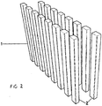
Figure 2 shows a three-dimensional plan view of the element shown inFigure 1 . -
Figure 3 shows a three-dimensional elevational view of the posts with a different angulation with respect to that depicted inFigures 1 and2 . -
Figure 4 shows a plan view of a wind attenuation diagram. - The protective visual and wind barrier of the present invention consists of precast reinforced concrete posts (1), separated from one another a variable distance and arranged in one, two or more lines or rows, generating both a visual barrier and a very effective protection against the wind, such that when the air strikes the first posts (1) it is split up into several gusts which are split up again into more gusts when they hit the second row (2) and so on and so forth when they hit the third row (not depicted herein), contemplating the possibility of a fourth row, a fifth row, etc., as needed, thereby generating a very significant reduction of the wind speed, creating a relatively calm atmosphere on the other side of the barrier.
- The way this barrier works can be observed in the plan view of the wind attenuation diagram shown in
Figure 4 . Starting from the existence of an area (3) exposed to strong gusts of wind (4), said wind is split up into gusts (5) when it goes through the posts (1), which gusts are split up again into more gusts when they go through the spaces between the posts (1) of the row (2) and so on and so forth until the protected area (6) is seen to have a considerable reduction of the impact of the wind, even being completely calm. - The slight permeability to the wind that exists allows preventing vertices and turbulences on the other side of same. By modifying the separation between posts (1), their angle in relation to the winds (see
Figure 3 ), the separation between lines (2), the height and section of the posts (1), a wide range of wind reductions can be configured, as needed, following the laws of aerodynamics. - It is not considered necessary to extend this description so that a person skilled in the art can understand the scope of the invention and the advantages derived from same. The terms used to draft this specification must always be interpreted in the broadest and most non-limiting manner. The materials, shape, size and arrangement of the elements will be susceptible to variation provided that it does not entail a change in the essential features of the invention claimed below.
Claims (1)
- A protective visual and wind barrier, characterized in that it consists of precast reinforced concrete posts (1), separated from one another a variable distance and arranged in one, two or more lines or rows, generating both a visual barrier and a very effective protection against the wind, such that when the air strikes the first posts (1), it is split up into several gusts which are split up again into more gusts when they hit the second row (2) and so on and so forth when they hit the third row (not depicted herein), contemplating the possibility of a fourth row, a fifth row, etc., as needed. Thereby generating a very significant reduction of the wind speed, creating a relatively calm atmosphere on the other side of the barrier.
Applications Claiming Priority (1)
| Application Number | Priority Date | Filing Date | Title |
|---|---|---|---|
| ES201600477U ES1167134Y (en) | 2016-07-06 | 2016-07-06 | Visual and wind protection screen |
Publications (2)
| Publication Number | Publication Date |
|---|---|
| EP3266936A1 true EP3266936A1 (en) | 2018-01-10 |
| EP3266936B1 EP3266936B1 (en) | 2021-12-01 |
Family
ID=57047581
Family Applications (1)
| Application Number | Title | Priority Date | Filing Date |
|---|---|---|---|
| EP17001145.6A Active EP3266936B1 (en) | 2016-07-06 | 2017-07-05 | Protective visual and wind barrier |
Country Status (2)
| Country | Link |
|---|---|
| EP (1) | EP3266936B1 (en) |
| ES (2) | ES1167134Y (en) |
Citations (3)
| Publication number | Priority date | Publication date | Assignee | Title |
|---|---|---|---|---|
| KR200431158Y1 (en) * | 2006-08-31 | 2006-11-15 | (주) 케이 이엔씨 | Bridge railing |
| KR20160077930A (en) * | 2014-12-24 | 2016-07-04 | 유흥식 | system and method for constructing wind passing type wind protection barrier |
| US20170073911A1 (en) * | 2015-09-11 | 2017-03-16 | Alion Energy, Inc. | Wind screens for photovoltaic arrays and methods thereof |
Family Cites Families (1)
| Publication number | Priority date | Publication date | Assignee | Title |
|---|---|---|---|---|
| CN101307592A (en) * | 2007-05-16 | 2008-11-19 | 中国药品生物制品检定所 | Wind sand blocking method and device |
-
2016
- 2016-07-06 ES ES201600477U patent/ES1167134Y/en not_active Expired - Fee Related
-
2017
- 2017-07-05 ES ES17001145T patent/ES2908153T3/en active Active
- 2017-07-05 EP EP17001145.6A patent/EP3266936B1/en active Active
Patent Citations (3)
| Publication number | Priority date | Publication date | Assignee | Title |
|---|---|---|---|---|
| KR200431158Y1 (en) * | 2006-08-31 | 2006-11-15 | (주) 케이 이엔씨 | Bridge railing |
| KR20160077930A (en) * | 2014-12-24 | 2016-07-04 | 유흥식 | system and method for constructing wind passing type wind protection barrier |
| US20170073911A1 (en) * | 2015-09-11 | 2017-03-16 | Alion Energy, Inc. | Wind screens for photovoltaic arrays and methods thereof |
Also Published As
| Publication number | Publication date |
|---|---|
| ES2908153T3 (en) | 2022-04-27 |
| EP3266936B1 (en) | 2021-12-01 |
| ES1167134Y (en) | 2017-01-02 |
| ES1167134U (en) | 2016-10-11 |
Similar Documents
| Publication | Publication Date | Title |
|---|---|---|
| Lull et al. | The La Bastida fortification: new light and new questions on Early Bronze Age societies in the western Mediterranean | |
| US5795099A (en) | Apparatus to control beach erosion | |
| Mohammed et al. | On shelterbelt design for combating sand invasion | |
| CN207405576U (en) | For the galvanized wire cage debris dam of mountain area RBS in channel direction | |
| CN101144266A (en) | Tsunami protection dike | |
| EP3266936A1 (en) | Protective visual and wind barrier | |
| CN105064315A (en) | Gas-solid separation type sand barrier | |
| JP6674220B2 (en) | Landing method by coral gravel accumulation, permeation structure and structure therefor | |
| Mohammed et al. | Moving sand and its consequences on and near a severely desertified environment and a protective shelterbelt | |
| JP4133517B2 (en) | Transmission type sabo dam | |
| CN208183655U (en) | A kind of Channel slope guard system | |
| JP6688155B2 (en) | Landification method by coral gravel deposition, permeable structure and structure therefor | |
| Volk et al. | Avalanche control with mitigation measures: a case study from Karaçam-Trabzon (Turkey) | |
| JP2012219606A (en) | Building and structure for tsunami protection measure | |
| JPH09228348A (en) | Sabo Dam and Sabo Method | |
| CN2934479Y (en) | Dust-blocking wall | |
| Mullineaux | Volcanic hazards on the island of Hawaii | |
| JP6688156B2 (en) | Landification method by coral gravel deposition, permeable structure and structure therefor | |
| Dafa-Alla et al. | The influence of optical porosity of tree windbreaks on windward wind speed, erosive force and sand deposition | |
| CN101046091A (en) | Wind blocking and sand fixing method with M-type warp knitted plastic net | |
| CN204728348U (en) | Mud-rock flow guard system | |
| JP6757962B2 (en) | Reticulated body | |
| CN201144410Y (en) | Ground sea fending groyne | |
| CN120331225B (en) | Goal-type sand trapping barriers, excavation-free sand fixation systems and methods for Gobi Desert regions | |
| RU139131U1 (en) | DEVICE FOR REDUCING THE DUST OUTLET FROM THE CONSTRUCTION SITE |
Legal Events
| Date | Code | Title | Description |
|---|---|---|---|
| PUAI | Public reference made under article 153(3) epc to a published international application that has entered the european phase |
Free format text: ORIGINAL CODE: 0009012 |
|
| STAA | Information on the status of an ep patent application or granted ep patent |
Free format text: STATUS: THE APPLICATION HAS BEEN PUBLISHED |
|
| AK | Designated contracting states |
Kind code of ref document: A1 Designated state(s): AL AT BE BG CH CY CZ DE DK EE ES FI FR GB GR HR HU IE IS IT LI LT LU LV MC MK MT NL NO PL PT RO RS SE SI SK SM TR |
|
| AX | Request for extension of the european patent |
Extension state: BA ME |
|
| STAA | Information on the status of an ep patent application or granted ep patent |
Free format text: STATUS: REQUEST FOR EXAMINATION WAS MADE |
|
| 17P | Request for examination filed |
Effective date: 20180702 |
|
| RBV | Designated contracting states (corrected) |
Designated state(s): AL AT BE BG CH CY CZ DE DK EE ES FI FR GB GR HR HU IE IS IT LI LT LU LV MC MK MT NL NO PL PT RO RS SE SI SK SM TR |
|
| STAA | Information on the status of an ep patent application or granted ep patent |
Free format text: STATUS: EXAMINATION IS IN PROGRESS |
|
| 17Q | First examination report despatched |
Effective date: 20190702 |
|
| GRAP | Despatch of communication of intention to grant a patent |
Free format text: ORIGINAL CODE: EPIDOSNIGR1 |
|
| STAA | Information on the status of an ep patent application or granted ep patent |
Free format text: STATUS: GRANT OF PATENT IS INTENDED |
|
| INTG | Intention to grant announced |
Effective date: 20210215 |
|
| GRAJ | Information related to disapproval of communication of intention to grant by the applicant or resumption of examination proceedings by the epo deleted |
Free format text: ORIGINAL CODE: EPIDOSDIGR1 |
|
| STAA | Information on the status of an ep patent application or granted ep patent |
Free format text: STATUS: EXAMINATION IS IN PROGRESS |
|
| GRAP | Despatch of communication of intention to grant a patent |
Free format text: ORIGINAL CODE: EPIDOSNIGR1 |
|
| STAA | Information on the status of an ep patent application or granted ep patent |
Free format text: STATUS: GRANT OF PATENT IS INTENDED |
|
| INTC | Intention to grant announced (deleted) | ||
| INTG | Intention to grant announced |
Effective date: 20210630 |
|
| GRAS | Grant fee paid |
Free format text: ORIGINAL CODE: EPIDOSNIGR3 |
|
| GRAA | (expected) grant |
Free format text: ORIGINAL CODE: 0009210 |
|
| STAA | Information on the status of an ep patent application or granted ep patent |
Free format text: STATUS: THE PATENT HAS BEEN GRANTED |
|
| AK | Designated contracting states |
Kind code of ref document: B1 Designated state(s): AL AT BE BG CH CY CZ DE DK EE ES FI FR GB GR HR HU IE IS IT LI LT LU LV MC MK MT NL NO PL PT RO RS SE SI SK SM TR |
|
| REG | Reference to a national code |
Ref country code: GB Ref legal event code: FG4D |
|
| REG | Reference to a national code |
Ref country code: AT Ref legal event code: REF Ref document number: 1451864 Country of ref document: AT Kind code of ref document: T Effective date: 20211215 Ref country code: CH Ref legal event code: EP |
|
| REG | Reference to a national code |
Ref country code: IE Ref legal event code: FG4D |
|
| REG | Reference to a national code |
Ref country code: DE Ref legal event code: R096 Ref document number: 602017050037 Country of ref document: DE |
|
| REG | Reference to a national code |
Ref country code: LT Ref legal event code: MG9D |
|
| REG | Reference to a national code |
Ref country code: NL Ref legal event code: MP Effective date: 20211201 |
|
| REG | Reference to a national code |
Ref country code: AT Ref legal event code: MK05 Ref document number: 1451864 Country of ref document: AT Kind code of ref document: T Effective date: 20211201 |
|
| REG | Reference to a national code |
Ref country code: ES Ref legal event code: FG2A Ref document number: 2908153 Country of ref document: ES Kind code of ref document: T3 Effective date: 20220427 |
|
| PG25 | Lapsed in a contracting state [announced via postgrant information from national office to epo] |
Ref country code: RS Free format text: LAPSE BECAUSE OF FAILURE TO SUBMIT A TRANSLATION OF THE DESCRIPTION OR TO PAY THE FEE WITHIN THE PRESCRIBED TIME-LIMIT Effective date: 20211201 Ref country code: LT Free format text: LAPSE BECAUSE OF FAILURE TO SUBMIT A TRANSLATION OF THE DESCRIPTION OR TO PAY THE FEE WITHIN THE PRESCRIBED TIME-LIMIT Effective date: 20211201 Ref country code: FI Free format text: LAPSE BECAUSE OF FAILURE TO SUBMIT A TRANSLATION OF THE DESCRIPTION OR TO PAY THE FEE WITHIN THE PRESCRIBED TIME-LIMIT Effective date: 20211201 Ref country code: BG Free format text: LAPSE BECAUSE OF FAILURE TO SUBMIT A TRANSLATION OF THE DESCRIPTION OR TO PAY THE FEE WITHIN THE PRESCRIBED TIME-LIMIT Effective date: 20220301 Ref country code: AT Free format text: LAPSE BECAUSE OF FAILURE TO SUBMIT A TRANSLATION OF THE DESCRIPTION OR TO PAY THE FEE WITHIN THE PRESCRIBED TIME-LIMIT Effective date: 20211201 |
|
| PG25 | Lapsed in a contracting state [announced via postgrant information from national office to epo] |
Ref country code: SE Free format text: LAPSE BECAUSE OF FAILURE TO SUBMIT A TRANSLATION OF THE DESCRIPTION OR TO PAY THE FEE WITHIN THE PRESCRIBED TIME-LIMIT Effective date: 20211201 Ref country code: PL Free format text: LAPSE BECAUSE OF FAILURE TO SUBMIT A TRANSLATION OF THE DESCRIPTION OR TO PAY THE FEE WITHIN THE PRESCRIBED TIME-LIMIT Effective date: 20211201 Ref country code: NO Free format text: LAPSE BECAUSE OF FAILURE TO SUBMIT A TRANSLATION OF THE DESCRIPTION OR TO PAY THE FEE WITHIN THE PRESCRIBED TIME-LIMIT Effective date: 20220301 Ref country code: LV Free format text: LAPSE BECAUSE OF FAILURE TO SUBMIT A TRANSLATION OF THE DESCRIPTION OR TO PAY THE FEE WITHIN THE PRESCRIBED TIME-LIMIT Effective date: 20211201 Ref country code: HR Free format text: LAPSE BECAUSE OF FAILURE TO SUBMIT A TRANSLATION OF THE DESCRIPTION OR TO PAY THE FEE WITHIN THE PRESCRIBED TIME-LIMIT Effective date: 20211201 Ref country code: GR Free format text: LAPSE BECAUSE OF FAILURE TO SUBMIT A TRANSLATION OF THE DESCRIPTION OR TO PAY THE FEE WITHIN THE PRESCRIBED TIME-LIMIT Effective date: 20220302 |
|
| PG25 | Lapsed in a contracting state [announced via postgrant information from national office to epo] |
Ref country code: NL Free format text: LAPSE BECAUSE OF FAILURE TO SUBMIT A TRANSLATION OF THE DESCRIPTION OR TO PAY THE FEE WITHIN THE PRESCRIBED TIME-LIMIT Effective date: 20211201 |
|
| PG25 | Lapsed in a contracting state [announced via postgrant information from national office to epo] |
Ref country code: SM Free format text: LAPSE BECAUSE OF FAILURE TO SUBMIT A TRANSLATION OF THE DESCRIPTION OR TO PAY THE FEE WITHIN THE PRESCRIBED TIME-LIMIT Effective date: 20211201 Ref country code: SK Free format text: LAPSE BECAUSE OF FAILURE TO SUBMIT A TRANSLATION OF THE DESCRIPTION OR TO PAY THE FEE WITHIN THE PRESCRIBED TIME-LIMIT Effective date: 20211201 Ref country code: RO Free format text: LAPSE BECAUSE OF FAILURE TO SUBMIT A TRANSLATION OF THE DESCRIPTION OR TO PAY THE FEE WITHIN THE PRESCRIBED TIME-LIMIT Effective date: 20211201 Ref country code: PT Free format text: LAPSE BECAUSE OF FAILURE TO SUBMIT A TRANSLATION OF THE DESCRIPTION OR TO PAY THE FEE WITHIN THE PRESCRIBED TIME-LIMIT Effective date: 20220401 Ref country code: EE Free format text: LAPSE BECAUSE OF FAILURE TO SUBMIT A TRANSLATION OF THE DESCRIPTION OR TO PAY THE FEE WITHIN THE PRESCRIBED TIME-LIMIT Effective date: 20211201 Ref country code: CZ Free format text: LAPSE BECAUSE OF FAILURE TO SUBMIT A TRANSLATION OF THE DESCRIPTION OR TO PAY THE FEE WITHIN THE PRESCRIBED TIME-LIMIT Effective date: 20211201 |
|
| REG | Reference to a national code |
Ref country code: DE Ref legal event code: R097 Ref document number: 602017050037 Country of ref document: DE |
|
| PG25 | Lapsed in a contracting state [announced via postgrant information from national office to epo] |
Ref country code: IS Free format text: LAPSE BECAUSE OF FAILURE TO SUBMIT A TRANSLATION OF THE DESCRIPTION OR TO PAY THE FEE WITHIN THE PRESCRIBED TIME-LIMIT Effective date: 20220401 |
|
| PLBE | No opposition filed within time limit |
Free format text: ORIGINAL CODE: 0009261 |
|
| STAA | Information on the status of an ep patent application or granted ep patent |
Free format text: STATUS: NO OPPOSITION FILED WITHIN TIME LIMIT |
|
| PG25 | Lapsed in a contracting state [announced via postgrant information from national office to epo] |
Ref country code: DK Free format text: LAPSE BECAUSE OF FAILURE TO SUBMIT A TRANSLATION OF THE DESCRIPTION OR TO PAY THE FEE WITHIN THE PRESCRIBED TIME-LIMIT Effective date: 20211201 Ref country code: AL Free format text: LAPSE BECAUSE OF FAILURE TO SUBMIT A TRANSLATION OF THE DESCRIPTION OR TO PAY THE FEE WITHIN THE PRESCRIBED TIME-LIMIT Effective date: 20211201 |
|
| 26N | No opposition filed |
Effective date: 20220902 |
|
| PG25 | Lapsed in a contracting state [announced via postgrant information from national office to epo] |
Ref country code: SI Free format text: LAPSE BECAUSE OF FAILURE TO SUBMIT A TRANSLATION OF THE DESCRIPTION OR TO PAY THE FEE WITHIN THE PRESCRIBED TIME-LIMIT Effective date: 20211201 |
|
| REG | Reference to a national code |
Ref country code: DE Ref legal event code: R119 Ref document number: 602017050037 Country of ref document: DE |
|
| PG25 | Lapsed in a contracting state [announced via postgrant information from national office to epo] |
Ref country code: MC Free format text: LAPSE BECAUSE OF FAILURE TO SUBMIT A TRANSLATION OF THE DESCRIPTION OR TO PAY THE FEE WITHIN THE PRESCRIBED TIME-LIMIT Effective date: 20211201 |
|
| REG | Reference to a national code |
Ref country code: CH Ref legal event code: PL |
|
| GBPC | Gb: european patent ceased through non-payment of renewal fee |
Effective date: 20220705 |
|
| REG | Reference to a national code |
Ref country code: BE Ref legal event code: MM Effective date: 20220731 |
|
| PG25 | Lapsed in a contracting state [announced via postgrant information from national office to epo] |
Ref country code: LU Free format text: LAPSE BECAUSE OF NON-PAYMENT OF DUE FEES Effective date: 20220705 Ref country code: LI Free format text: LAPSE BECAUSE OF NON-PAYMENT OF DUE FEES Effective date: 20220731 Ref country code: FR Free format text: LAPSE BECAUSE OF NON-PAYMENT OF DUE FEES Effective date: 20220731 Ref country code: CH Free format text: LAPSE BECAUSE OF NON-PAYMENT OF DUE FEES Effective date: 20220731 |
|
| PG25 | Lapsed in a contracting state [announced via postgrant information from national office to epo] |
Ref country code: IT Free format text: LAPSE BECAUSE OF FAILURE TO SUBMIT A TRANSLATION OF THE DESCRIPTION OR TO PAY THE FEE WITHIN THE PRESCRIBED TIME-LIMIT Effective date: 20211201 Ref country code: GB Free format text: LAPSE BECAUSE OF NON-PAYMENT OF DUE FEES Effective date: 20220705 Ref country code: DE Free format text: LAPSE BECAUSE OF NON-PAYMENT OF DUE FEES Effective date: 20230201 Ref country code: BE Free format text: LAPSE BECAUSE OF NON-PAYMENT OF DUE FEES Effective date: 20220731 |
|
| PG25 | Lapsed in a contracting state [announced via postgrant information from national office to epo] |
Ref country code: IE Free format text: LAPSE BECAUSE OF NON-PAYMENT OF DUE FEES Effective date: 20220705 |
|
| PG25 | Lapsed in a contracting state [announced via postgrant information from national office to epo] |
Ref country code: HU Free format text: LAPSE BECAUSE OF FAILURE TO SUBMIT A TRANSLATION OF THE DESCRIPTION OR TO PAY THE FEE WITHIN THE PRESCRIBED TIME-LIMIT; INVALID AB INITIO Effective date: 20170705 |
|
| PG25 | Lapsed in a contracting state [announced via postgrant information from national office to epo] |
Ref country code: MK Free format text: LAPSE BECAUSE OF FAILURE TO SUBMIT A TRANSLATION OF THE DESCRIPTION OR TO PAY THE FEE WITHIN THE PRESCRIBED TIME-LIMIT Effective date: 20211201 Ref country code: CY Free format text: LAPSE BECAUSE OF FAILURE TO SUBMIT A TRANSLATION OF THE DESCRIPTION OR TO PAY THE FEE WITHIN THE PRESCRIBED TIME-LIMIT Effective date: 20211201 |
|
| PG25 | Lapsed in a contracting state [announced via postgrant information from national office to epo] |
Ref country code: MT Free format text: LAPSE BECAUSE OF FAILURE TO SUBMIT A TRANSLATION OF THE DESCRIPTION OR TO PAY THE FEE WITHIN THE PRESCRIBED TIME-LIMIT Effective date: 20211201 |
|
| PG25 | Lapsed in a contracting state [announced via postgrant information from national office to epo] |
Ref country code: TR Free format text: LAPSE BECAUSE OF FAILURE TO SUBMIT A TRANSLATION OF THE DESCRIPTION OR TO PAY THE FEE WITHIN THE PRESCRIBED TIME-LIMIT Effective date: 20211201 |
|
| PGFP | Annual fee paid to national office [announced via postgrant information from national office to epo] |
Ref country code: ES Payment date: 20251024 Year of fee payment: 9 |