EP3266849A1 - Fluorophore - Google Patents
Fluorophore Download PDFInfo
- Publication number
- EP3266849A1 EP3266849A1 EP16758724.5A EP16758724A EP3266849A1 EP 3266849 A1 EP3266849 A1 EP 3266849A1 EP 16758724 A EP16758724 A EP 16758724A EP 3266849 A1 EP3266849 A1 EP 3266849A1
- Authority
- EP
- European Patent Office
- Prior art keywords
- phosphor
- mcusi
- excitation
- phase
- intensity
- Prior art date
- Legal status (The legal status is an assumption and is not a legal conclusion. Google has not performed a legal analysis and makes no representation as to the accuracy of the status listed.)
- Granted
Links
Images



Classifications
-
- C—CHEMISTRY; METALLURGY
- C09—DYES; PAINTS; POLISHES; NATURAL RESINS; ADHESIVES; COMPOSITIONS NOT OTHERWISE PROVIDED FOR; APPLICATIONS OF MATERIALS NOT OTHERWISE PROVIDED FOR
- C09D—COATING COMPOSITIONS, e.g. PAINTS, VARNISHES OR LACQUERS; FILLING PASTES; CHEMICAL PAINT OR INK REMOVERS; INKS; CORRECTING FLUIDS; WOODSTAINS; PASTES OR SOLIDS FOR COLOURING OR PRINTING; USE OF MATERIALS THEREFOR
- C09D7/00—Features of coating compositions, not provided for in group C09D5/00; Processes for incorporating ingredients in coating compositions
- C09D7/40—Additives
-
- C—CHEMISTRY; METALLURGY
- C09—DYES; PAINTS; POLISHES; NATURAL RESINS; ADHESIVES; COMPOSITIONS NOT OTHERWISE PROVIDED FOR; APPLICATIONS OF MATERIALS NOT OTHERWISE PROVIDED FOR
- C09K—MATERIALS FOR MISCELLANEOUS APPLICATIONS, NOT PROVIDED FOR ELSEWHERE
- C09K11/00—Luminescent materials, e.g. electroluminescent or chemiluminescent
- C09K11/08—Luminescent materials, e.g. electroluminescent or chemiluminescent containing inorganic luminescent materials
- C09K11/59—Luminescent materials, e.g. electroluminescent or chemiluminescent containing inorganic luminescent materials containing silicon
-
- A—HUMAN NECESSITIES
- A61—MEDICAL OR VETERINARY SCIENCE; HYGIENE
- A61B—DIAGNOSIS; SURGERY; IDENTIFICATION
- A61B5/00—Measuring for diagnostic purposes; Identification of persons
- A61B5/0059—Measuring for diagnostic purposes; Identification of persons using light, e.g. diagnosis by transillumination, diascopy, fluorescence
- A61B5/0062—Arrangements for scanning
- A61B5/0066—Optical coherence imaging
-
- A—HUMAN NECESSITIES
- A61—MEDICAL OR VETERINARY SCIENCE; HYGIENE
- A61B—DIAGNOSIS; SURGERY; IDENTIFICATION
- A61B5/00—Measuring for diagnostic purposes; Identification of persons
- A61B5/0059—Measuring for diagnostic purposes; Identification of persons using light, e.g. diagnosis by transillumination, diascopy, fluorescence
- A61B5/0071—Measuring for diagnostic purposes; Identification of persons using light, e.g. diagnosis by transillumination, diascopy, fluorescence by measuring fluorescence emission
-
- C—CHEMISTRY; METALLURGY
- C09—DYES; PAINTS; POLISHES; NATURAL RESINS; ADHESIVES; COMPOSITIONS NOT OTHERWISE PROVIDED FOR; APPLICATIONS OF MATERIALS NOT OTHERWISE PROVIDED FOR
- C09D—COATING COMPOSITIONS, e.g. PAINTS, VARNISHES OR LACQUERS; FILLING PASTES; CHEMICAL PAINT OR INK REMOVERS; INKS; CORRECTING FLUIDS; WOODSTAINS; PASTES OR SOLIDS FOR COLOURING OR PRINTING; USE OF MATERIALS THEREFOR
- C09D1/00—Coating compositions, e.g. paints, varnishes or lacquers, based on inorganic substances
-
- C—CHEMISTRY; METALLURGY
- C09—DYES; PAINTS; POLISHES; NATURAL RESINS; ADHESIVES; COMPOSITIONS NOT OTHERWISE PROVIDED FOR; APPLICATIONS OF MATERIALS NOT OTHERWISE PROVIDED FOR
- C09D—COATING COMPOSITIONS, e.g. PAINTS, VARNISHES OR LACQUERS; FILLING PASTES; CHEMICAL PAINT OR INK REMOVERS; INKS; CORRECTING FLUIDS; WOODSTAINS; PASTES OR SOLIDS FOR COLOURING OR PRINTING; USE OF MATERIALS THEREFOR
- C09D201/00—Coating compositions based on unspecified macromolecular compounds
-
- C—CHEMISTRY; METALLURGY
- C09—DYES; PAINTS; POLISHES; NATURAL RESINS; ADHESIVES; COMPOSITIONS NOT OTHERWISE PROVIDED FOR; APPLICATIONS OF MATERIALS NOT OTHERWISE PROVIDED FOR
- C09D—COATING COMPOSITIONS, e.g. PAINTS, VARNISHES OR LACQUERS; FILLING PASTES; CHEMICAL PAINT OR INK REMOVERS; INKS; CORRECTING FLUIDS; WOODSTAINS; PASTES OR SOLIDS FOR COLOURING OR PRINTING; USE OF MATERIALS THEREFOR
- C09D5/00—Coating compositions, e.g. paints, varnishes or lacquers, characterised by their physical nature or the effects produced; Filling pastes
- C09D5/22—Luminous paints
-
- C—CHEMISTRY; METALLURGY
- C09—DYES; PAINTS; POLISHES; NATURAL RESINS; ADHESIVES; COMPOSITIONS NOT OTHERWISE PROVIDED FOR; APPLICATIONS OF MATERIALS NOT OTHERWISE PROVIDED FOR
- C09D—COATING COMPOSITIONS, e.g. PAINTS, VARNISHES OR LACQUERS; FILLING PASTES; CHEMICAL PAINT OR INK REMOVERS; INKS; CORRECTING FLUIDS; WOODSTAINS; PASTES OR SOLIDS FOR COLOURING OR PRINTING; USE OF MATERIALS THEREFOR
- C09D7/00—Features of coating compositions, not provided for in group C09D5/00; Processes for incorporating ingredients in coating compositions
- C09D7/40—Additives
- C09D7/60—Additives non-macromolecular
- C09D7/61—Additives non-macromolecular inorganic
-
- C—CHEMISTRY; METALLURGY
- C09—DYES; PAINTS; POLISHES; NATURAL RESINS; ADHESIVES; COMPOSITIONS NOT OTHERWISE PROVIDED FOR; APPLICATIONS OF MATERIALS NOT OTHERWISE PROVIDED FOR
- C09K—MATERIALS FOR MISCELLANEOUS APPLICATIONS, NOT PROVIDED FOR ELSEWHERE
- C09K11/00—Luminescent materials, e.g. electroluminescent or chemiluminescent
- C09K11/08—Luminescent materials, e.g. electroluminescent or chemiluminescent containing inorganic luminescent materials
- C09K11/59—Luminescent materials, e.g. electroluminescent or chemiluminescent containing inorganic luminescent materials containing silicon
- C09K11/592—Chalcogenides
-
- H—ELECTRICITY
- H05—ELECTRIC TECHNIQUES NOT OTHERWISE PROVIDED FOR
- H05B—ELECTRIC HEATING; ELECTRIC LIGHT SOURCES NOT OTHERWISE PROVIDED FOR; CIRCUIT ARRANGEMENTS FOR ELECTRIC LIGHT SOURCES, IN GENERAL
- H05B33/00—Electroluminescent light sources
- H05B33/12—Light sources with substantially two-dimensional [2D] radiating surfaces
- H05B33/14—Light sources with substantially two-dimensional [2D] radiating surfaces characterised by the chemical or physical composition or the arrangement of the electroluminescent material, or by the simultaneous addition of the electroluminescent material in or onto the light source
-
- H—ELECTRICITY
- H10—SEMICONDUCTOR DEVICES; ELECTRIC SOLID-STATE DEVICES NOT OTHERWISE PROVIDED FOR
- H10H—INORGANIC LIGHT-EMITTING SEMICONDUCTOR DEVICES HAVING POTENTIAL BARRIERS
- H10H20/00—Individual inorganic light-emitting semiconductor devices having potential barriers, e.g. light-emitting diodes [LED]
- H10H20/80—Constructional details
- H10H20/85—Packages
- H10H20/851—Wavelength conversion means
- H10H20/8511—Wavelength conversion means characterised by their material, e.g. binder
- H10H20/8512—Wavelength conversion materials
Definitions
- the present invention relates to a phosphor, which is excited by visible light, capable of emitting near-infrared light.
- a near-infrared spectrometer using a near-infrared luminescent device is particularly suitable for evaluating objects, which contain a large amount of water, such as biological objects, fruits and vegetables.
- optical coherence tomography uses near-infrared light
- the optical coherence tomography has characteristics that biological damage thereof is lower than that of a general X-ray tomography, and spatial resolution of tomographic images is excellent.
- a novel fluorescent paint or fluorescent paint printed matter can be developed.
- a UV light fluorescent pigment has been mainly used for forgery-proof printing utilized for paper-money or the like. If this can replace with near-infrared fluorescent pigment, novel forgery-proof printing in which the forgery, which cannot be detected with the naked eye, can be detected by a solid-state imaging device using a photo-diode made of silicon, InGaAs or the like, or equipment using a photomultiplier tube, becomes possible.
- the near-infrared luminescent phosphor which is excited by visible light, capable of emitting near-infrared light can be used for various applications in the future.
- Patent Document 1 Japanese Patent Application Laid-Open No. 2008-185378 discloses a near-infrared luminescent phosphor which contains Yb 2 O 3 and Nd 2 O 3 as an infrared glass phosphor used for OCT apparatus, further contains glass comprising Bi 2 O 3 and B 2 O 3 , and is excited by blue light.
- Patent Document 2 Japanese Translation of PCT International Application Publication No. 2004-526330 discloses a near-infrared luminescent body which is near-infrared light-excited by a glass-ceramic material in which transition metal ions are doped, and also proposes its expansion to OCT apparatus.
- These phosphors have an advantage of having a wide fluorescence spectrum.
- the phosphors are practically used, there has been a problem that the excited spectrum is narrow.
- Patent Document 1 Japanese Patent Application Laid-Open No. 2008-185378
- the infrared glass phosphor which contains Yb 2 O 3 and Nd 2 O 3 as the infrared glass phosphor used for OCT apparatus, and further contains glass comprising Bi 2 O 3 and B 2 O 3 , has been disclosed at best.
- the present invention is to provide a novel phosphor, which is excited by visible light of a wide band, capable of emitting near-infrared light with high intensity.
- the present invention proposes a phosphor comprising a crystal phase represented by a formula (1): MCuSi 2 O 6 (where M comprises one or two or more of Ba, Sr and Ca) and a crystal phase represented by a formula (2): MCuSi 4 O 10 (where M comprises one or two or more of Ba, Sr and Ca), wherein, in an X-ray diffraction (XRD) pattern obtained by powder XRD measurement using CuK ⁇ rays, a ratio ⁇ of a diffraction peak intensity of MCuSi 4 O 10 with respect to a diffraction peak intensity of MCuSi 2 O 6 is 0 ⁇ ⁇ ⁇ 0.50.
- XRD X-ray diffraction
- the phosphor proposed by the present invention is excited by visible light of a wide band, and can emit near-infrared light with high intensity. Therefore, as described above, the phosphor can be suitably used as a phosphor constituting a luminescent device mounted on a near-infrared spectrometer or an optical coherence tomography (OCT), and further as a wavelength conversion material constituting a light-receiving device mounted on a solar battery, a solar power generator or the like. In addition, the phosphor proposed by the present invention can be suitably used as a phosphor which is contained in fluorescent paint used for a fluorescent paint printed matter or a printed matter having an image recognition part of near-infrared light luminescence.
- OCT optical coherence tomography
- the phosphor according to an example of the present embodiment is a phosphor containing at least a crystal phase represented by a formula (1) : MCuSi 2 O 6 (where M comprises one or two or more of Ba, Sr and Ca) (referred to as “MCuSi 2 O 6 crystal phase”) and a crystal phase represented by a formula (2): MCuSi 4 O 10 (where M comprises one or two or more of Ba, Sr and Ca) (referred to as "MCuSi 4 O 10 crystal phase").
- a band of an excitation spectrum can be expanded while maintaining fluorescence spectrum intensity.
- the present phosphor may be a polycrystal body comprising a plurality of crystal phases, or a mixture containing a plurality of crystal phases.
- the "crystal phase” when the "crystal phase" contains MCuSi 2 O 6 as a main component, the "crystal phase” may also contain the other components, for example, a component present in a crystal phase, which cannot be detected by XRD. Same applies to another crystal phase.
- the MCuSi 2 O 6 crystal phase is preferably a main crystal phase.
- a diffraction peak intensity derived from the crystal phase of MCuSi 2 O 6 is larger than a diffraction peak intensity derived from any other crystal phases.
- a ratio ⁇ of a diffraction peak intensity of MCuSi 4 O 10 with respect to a diffraction peak intensity of MCuSi 2 O 6 is 0 ⁇ ⁇ ⁇ 0.50.
- a band of an excitation spectrum can be expanded while maintaining fluorescence spectrum intensity.
- a ratio ⁇ of a diffraction peak intensity of MCuSi 4 O 10 with respect to a diffraction peak intensity of MCuSi 2 O 6 is 0 ⁇ ⁇ ⁇ 0.50.
- it is more preferably 0 ⁇ ⁇ ⁇ 0.31, and furthermore preferably 0 ⁇ ⁇ ⁇ 0.10.
- the content of each of the crystal phases is expressed by the diffraction peak intensity of each of the crystal phases in the XRD pattern, not by chemical analysis. This is because when the content of each of the crystal phases is represented by chemical analysis, it is largely affected by a blending amount of an additive such as flux, and thus the characteristics of the present phosphor are difficult to be expressed accurately. In contrast, when the content of each of the crystal phases is expressed by the diffraction peak intensity of each of the crystal phases in the XRD pattern, the effect by the blending amount of the additive can be suppressed, and thus the characteristics of the present phosphor can be expressed accurately.
- the present phosphor further contains a SiO 2 crystal phase.
- the present phosphor may not contain the SiO 2 crystal phase.
- a ratio ⁇ of a diffraction peak intensity of SiO 2 with respect to a diffraction peak intensity of MCuSi 2 O 6 is 0 ⁇ a ⁇ 0.45.
- a ratio ⁇ of a diffraction peak intensity of SiO 2 is 0 ⁇ ⁇ ⁇ 0.45, more preferably 0.16 ⁇ a, and even more preferably a ⁇ 0.35. Among others, it is particularly preferably ⁇ ⁇ 0.3, and furthermore preferably 0.20 ⁇ a or a ⁇ 0.25.
- the present phosphor may contain, or may not contain a BaSi 2 O 5 crystal phase. This is because, by containing the BaSi 2 O 5 crystal phase, both an advantage and a disadvantage are not confirmed at the present time.
- a part of Cu in the formula (1) : MCuSi 2 O 6 or the formula (2) : MCuSi 4 O 10 , or both the formulae is substituted by Mg or Zn, or both of these.
- Mg or Zn or both of these.
- the present phosphor further contains one or two or more elements selected from a group consisting of Li, Na, K, B, P, F, Cl, Br and I.
- the contents of these elements are preferably 0.005 to 3% by mass. Among others, it is more preferably 0.008% by mass or more or 2% by mass or less, and even more preferably 0.01% by mass or more or 1% by mass or less.
- luminescent peak intensity can be consequently enhanced.
- These elements can be added as a part of a sintering aid.
- the present phosphor may contain element components other than the above when the contents of the element components other than the above are less than 20% by mass. This is because, it can be considered that the characteristics of the present phosphor are not affected by the other element components in such an amount.
- the present phosphor is not limited to the forms such as a film shape, a plate shape and a particle shape. However, from a point of view of workability to a luminescent device-mounted unit or a printed matter to be used, the form of the present phosphor is preferably a particle shape.
- the present phosphor can be produced by the following production method.
- the production method of the present phosphor is not limited to the production method to be described below.
- the present phosphor can be obtained by mixing M element raw material in the formula (1): MCuSi 2 O 6 , Cu raw material, and silicon raw material, adding flux (sintering aid) if necessary, and calcining the mixture.
- examples of the M element raw material may include an oxide of M elements (one or two or more elements of Ba, Sr and Ca), carbonate, nitrate, acetate, and the like.
- Examples of the Cu raw material may include an oxide of Cu, carbonate, sulfate, metal, and the like.
- Examples of the silicon raw material may include an oxide of silicon, carbide, nitride, silicon, and the like.
- a reducing agent is not added.
- a blending ratio (molar ratio) of the M element raw material and the Cu raw material is preferably 1.5 : 1.0 to 0.8 : 1.0. Among others, it is more preferably 1.3 : 1.0 to 0.9 : 1.0, and even more preferably 1.2 : 1.0 to 1.0 : 1.0.
- a blending ratio (mass ratio) of the Cu raw material and the silicon raw material is preferably 1.0 : 2.0 to 1.0 : 5.0. Among others, it is more preferably 1.0 : 3.0 to 1.0 : 4.5, and even more preferably 1.0 : 3.5 to 1.0 : 4.2.
- the flux (sintering aid) may include a flux (sintering aid) containing one or two or more elements selected from a group consisting of Li, Na, K, B, P, F, Cl, Br and I. Among others, it is more preferably Li, Na, K, B, F, Cl, and the like.
- a blending amount (mass ratio) of the flux (sintering aid) is preferably 0.1 to 15% with respect to a total weight obtained by mixing the M element raw material, the Cu raw material and the silicon raw material. Among others, it is more preferably 1% or more or 10% or less, and even more preferably 2% or more or 7% or less.
- any atmosphere can be appropriately employed.
- an inert gas atmosphere an air atmosphere, an acidic atmosphere and the like can be employed.
- a calcination temperature may be 700 to 1,100°C. This is because when it is less than 700°C, a reaction is hardly progressed. In contrast, when it is 1,100°C or more, there is a possibility of melting.
- the calcination may be repeated several times. That is, for example, the first calcination is performed in a temperature range of 700 to 900°C, the calcined powder thus obtained is crushed, and then the second calcination can be also performed in a temperature range of 800 to 1,100°C.
- the calcined powder is washed with an acidic solution such as water and hydrochloric acid after the first calcination, and then the second calcination can be also performed.
- an acidic solution such as water and hydrochloric acid
- the blending amount of the sintering aid can be more appropriately adjusted to each calcination step, and thus the element contents of Li, Na, K, B, P, F, Cl, Br and I contained in the present phosphor which is a final product can be also easily controlled in an appropriate range.
- the present phosphor is excited by visible light, and can emit near-infrared light. That is, the present phosphor has characteristics of having an excitation spectrum in a visible light region (380 nm to 750 nm), and having a luminescent peak in a near-infrared region (750 nm to 2,500 nm).
- an excitation band width of 80% or more of the maximum excitation intensity can be set to 90 nm or more, more preferably 100 nm or more, and even more preferably 150 nm or more.
- the present phosphor has a characteristic that a luminescent intensity in a near-infrared region can be further enhanced.
- the present phosphor is mixed with an organic resin or an inorganic filler, for example, glass particles, a metal oxide or the like, and further a solvent, a dispersant or the like if necessary, coated and formed as a liquid composition, and then solidified via drying or/and curing.
- an organic resin or an inorganic filler for example, glass particles, a metal oxide or the like
- a solvent, a dispersant or the like if necessary
- the present phosphor Since the present phosphor is excited by visible light, and can emit near-infrared light, the present phosphor can be used for a near-infrared luminescent device.
- the present phosphor can be suitably used as a phosphor constituting a luminescent device mounted on luminescent device mounted units such as a near-infrared spectrometer and an optical coherence tomography (OCT), as a wavelength conversion material constituting a light-receiving device mounted on light-receiving device mounted units such as a solar power generator, and as a phosphor which is contained in fluorescent paint used for a fluorescent paint printed matter or a printed matter having an image recognition part of near-infrared light luminescence.
- OCT optical coherence tomography
- the near-infrared luminescent device containing the present phosphor (referred to as “the present near-infrared luminescent device") is used for a spectrometer
- the spectrometer can be used for an evaluation apparatus of biological objects, fruits and vegetables, or the like.
- the present phosphor is mounted as a wavelength conversion material of a near-infrared light source.
- the light-receiving device containing the present phosphor when used for a solar power generator, a visible light component of sunlight can be converted into near-infrared light, and thus the power generation efficiency can be further enhanced.
- the present phosphor can be mounted as a wavelength conversion material on a light-receiving side.
- a light-receiving device using a silicon photo-diode has high spectral sensitivity in a wavelength band of near-infrared light of 800 to 1,000 nm, and thus the present phosphor is suitable as a wavelength conversion material having an excellent matching property with 900 to 950 nm, which is a peak wavelength band of near-infrared luminescence of the present phosphor.
- the present phosphor emits near-infrared light even when electron rays, X-rays or the like are used as an excitation source, for example, when using X-rays as an excitation source, applications into an X-ray diagnostic apparatus for medical or security as a scintillation material, or the like are possible.
- a fluorescent paint is produced by using the present phosphor
- a fluorescent paint printed matter which is used for forgery-proof printing utilized for paper-money or the like can be produced, and then novel forgery-proof printing in which the forgery, which cannot be detected with the naked eye, can be detected by a solid-state imaging device using a photo-diode made of silicon, InGaAs or the like, or equipment using a photomultiplier tube, can be performed.
- These fluorescent paints are mixed with a fluidity adjusting material of inorganic components or organic components, an organic solvent, or the like, as setting transparent resin components as matrix in addition to the present phosphor, and prepared as ink or paste.
- the resin component may include an epoxy resin, a phenol resin, a silicone resin, an acrylic resin, and polymethyl methacrylate. Additionally, glass particles, which are light scattering components, may be mixed if necessary.
- Each of the phosphors (samples) obtained in Examples and Comparative Examples served as a sample for powder X-ray diffraction measurement (XRD).
- the sample was mounted on a holder, and angles and intensities of the diffracted rays were measured using MXP18 (manufactured by Bruker AXS) under the following conditions, thereby obtaining an XRD pattern.
- each of the phosphors (samples) obtained in Examples and Comparative Examples served as a sample for luminescent characteristic measurement, and an excitation spectrum and a fluorescence spectrum were measured using a spectrofluorometer (FP-8600, manufactured by JASCO Corp.) under conditions in which the band widths of both the excitation side and the fluorescence side were 10 nm and the scanning speed was 1,000 nm/min.
- FP-8600 spectrofluorometer
- the excitation spectrum was evaluated by the following criteria.
- Each of the fluorescence spectra in excitation wavelengths (620 nm, 570 nm and 520 nm) was evaluated by the following criteria.
- the four evaluation items that is, the excitation band width of the evaluated excitation spectrum and the peak intensity of the fluorescence spectrum in each of the excitation wavelengths (620 nm, 570 nm and 520 nm), were evaluated by the following criteria.
- BaCO 3 , CuO and SiO 2 were mixed such that a molar ratio of those was 1 : 1 : 3.5. Further, BaCl 2 as flux was added to the mixture such that the total amount of the mixture became 3% by mass, and was mixed. The mixture was put in an alumina crucible, and was calcined at 1,000°C for 24 hours under the air, thereby obtaining a phosphor (sample).
- the obtained phosphor was a compound composed of a BaCuSi 2 O 6 phase as a main crystal phase, and containing a SiO 2 phase, a trace amount of BaCuSi 4 O 10 phase, and a BaSi 2 O 5 phase.
- a Cl amount contained in the compound was 0.02% by mass by the fluorescence X-ray measurement.
- BaCO 3 , CuO and SiO 2 were mixed such that a molar ratio of those was 1 : 1 : 4. Further, BaCl 2 as flux was added to the mixture such that the total amount of the mixture became 3% by mass, and was mixed. The mixture was put in an alumina crucible, and was calcined at 1,000°C for 24 hours under the air, thereby obtaining a phosphor (sample).
- the obtained phosphor was a compound composed of a BaCuSi 2 O 6 phase as a main crystal phase, and containing a SiO 2 phase, a BaCuSi 4 O 10 phase, and a BaSi 2 O 5 phase.
- a Cl amount contained in the compound was 0.01% by mass by the fluorescence X-ray measurement.
- BaCO 3 , CuO and SiO 2 were weighed such that a molar ratio of those was 1 : 1 : 4, and were wet mixed in acetone.
- the mixture was put in an alumina crucible, and was calcined at 960°C for 16 hours under the air, thereby obtaining a phosphor (sample).
- the obtained phosphor was a single phase of BaCuSi 4 O 10 .
- halogen elements such as Cl
- alkaline metals such as Na
- P in the phosphor was less than 0.005% by mass by the fluorescence X-ray measurement.
- BaCO 3 , CuO and SiO 2 were mixed such that a molar ratio of those was 1 : 1 : 2. Then, the mixture was put in an alumina crucible, and was calcined at 1,000°C for 24 hours under the air, thereby obtaining a phosphor (sample).
- the obtained phosphor was a compound composed of a BaCuSi 2 O 6 phase as a main crystal phase, and containing a trace amount of BaSi 2 O 5 phase.
- BaCO 3 , CuO and SiO 2 were mixed such that a molar ratio of those was 1 : 1 : 3. Then, the mixture was put in an alumina crucible, and was calcined at 1,000°C for 24 hours under the air, thereby obtaining a phosphor (sample).
- the obtained phosphor was a compound composed of a SiO 2 phase as a main crystal phase, and containing a BaCuSi 2 O 6 phase and a trace amount of BaSi 2 O 5 phase.
- BaCO 3 , Cu 2 CO 3 ⁇ (OH) 2 ⁇ H 2 O and SiO 2 were mixed such that a molar ratio of those was 1 : 0.5 : 4, and were wet mixed in ethanol.
- the mixture was put in an alumina crucible, and was calcined at 1,100°C for 24 hours under the air, thereby obtaining a phosphor (sample).
- the obtained phosphor was a compound composed of a BaCuSi 4 O 10 phase and a BaCuSi 2 O 6 phase as a main crystal phase, and containing a SiO 2 phase and a BaSi 2 O 5 phase.
- Fig.7 is a drawing which illustrates excitation spectra and fluorescence spectra of Example 1 and Comparative Example 1 as relative values when the maximum values of excitation intensity and fluorescence intensity in the vertical axis are normalized as 1.
- Example 1 shows that wavelength dependency is small, and an intensity difference in a range of 500 nm to 650 nm falls within 20% or less. That is, if the excitation is made within a wavelength of this range, it is found that a fluorescent intensity difference can be suppressed within 20%, and the wavelength dependency is small. This shows that if a white light source or a plurality of single-color light sources is used, conversion efficiency to near-infrared light can be further enhanced.
- Comparative Example 1 dependency of an excitation wavelength is large, and an excitation wavelength band in which a fluorescent intensity difference can be suppressed within 20%, is limited to a narrow range of 615 to 680 nm. That is, a usable excitation light source is limited to a red light source, and the conversion efficiency to near-infrared light is suppressed low.
- Fig.8 is a drawing which illustrates excitation spectra and fluorescence spectra of Example 1, Example 2 and Comparative Example 4 when the maximum values of excitation intensity and fluorescence intensity in the vertical axis are normalized as 1.
- Fig.9 is a drawing which compares excitation spectrum intensities to fluorescence spectrum intensities of Example 1, Example 2 and Comparative Example 4.
- Example 1 The excitation spectrum intensities and the fluorescence spectrum intensities of Example 1, Comparative Example 2 and 3 were compared (see Table 1).
- alkaline earth metals such as Ba, Sr and Ca have similar properties, even when using Sr or Ca instead of Ba, or with Ba, it can be considered that the same effect as the above Examples can be obtained.
Landscapes
- Chemical & Material Sciences (AREA)
- Life Sciences & Earth Sciences (AREA)
- Engineering & Computer Science (AREA)
- Health & Medical Sciences (AREA)
- Materials Engineering (AREA)
- Organic Chemistry (AREA)
- Wood Science & Technology (AREA)
- Inorganic Chemistry (AREA)
- Pathology (AREA)
- Animal Behavior & Ethology (AREA)
- Physics & Mathematics (AREA)
- Biophysics (AREA)
- Veterinary Medicine (AREA)
- Biomedical Technology (AREA)
- Heart & Thoracic Surgery (AREA)
- Medical Informatics (AREA)
- Molecular Biology (AREA)
- Surgery (AREA)
- Public Health (AREA)
- General Health & Medical Sciences (AREA)
- Radiology & Medical Imaging (AREA)
- Nuclear Medicine, Radiotherapy & Molecular Imaging (AREA)
- Luminescent Compositions (AREA)
- Paints Or Removers (AREA)
Abstract
Description
- The present invention relates to a phosphor, which is excited by visible light, capable of emitting near-infrared light.
- In a case of evaluating objects by using a spectrometer, light in a near-infrared region is less absorbed by moisture. Therefore, a near-infrared spectrometer using a near-infrared luminescent device is particularly suitable for evaluating objects, which contain a large amount of water, such as biological objects, fruits and vegetables.
- In addition, since an optical coherence tomography (OCT) uses near-infrared light, the optical coherence tomography (OCT) has characteristics that biological damage thereof is lower than that of a general X-ray tomography, and spatial resolution of tomographic images is excellent.
- Further, in a solar battery or a solar power generator using silicon, photo-responsibility of silicon in a near-infrared region is the highest. Therefore, if visible light can be converted into near-infrared light, the power generation efficiency can be further enhanced.
- Meanwhile, when a phosphor capable of emitting near-infrared light is used, a novel fluorescent paint or fluorescent paint printed matter can be developed. For example, conventionally, a UV light fluorescent pigment has been mainly used for forgery-proof printing utilized for paper-money or the like. If this can replace with near-infrared fluorescent pigment, novel forgery-proof printing in which the forgery, which cannot be detected with the naked eye, can be detected by a solid-state imaging device using a photo-diode made of silicon, InGaAs or the like, or equipment using a photomultiplier tube, becomes possible.
- As such, it is expected that the near-infrared luminescent phosphor, which is excited by visible light, capable of emitting near-infrared light can be used for various applications in the future.
- For example, Patent Document 1 (Japanese Patent Application Laid-Open No.
2008-185378 PCT International Application Publication No. 2004-526330 - These phosphors have an advantage of having a wide fluorescence spectrum. However, when the phosphors are practically used, there has been a problem that the excited spectrum is narrow. Particularly, there has been a demand of developing a phosphor that is excited by a wide band of visible light, and has a wide fluorescence spectrum.
- However, there are few kinds of near-infrared luminescent phosphor which have been conventionally known. For example, in Patent Document 1 (Japanese Patent Application Laid-Open No.
2008-185378 -
- Patent Document 1: Japanese Patent Application Laid-Open No.
2008-185378 - Patent Document 2: Japanese Translation of
PCT International Application Publication No. 2004-526330 - Thus, the present invention is to provide a novel phosphor, which is excited by visible light of a wide band, capable of emitting near-infrared light with high intensity.
- The present invention proposes a phosphor comprising a crystal phase represented by a formula (1): MCuSi2O6 (where M comprises one or two or more of Ba, Sr and Ca) and a crystal phase represented by a formula (2): MCuSi4O10 (where M comprises one or two or more of Ba, Sr and Ca), wherein, in an X-ray diffraction (XRD) pattern obtained by powder XRD measurement using CuKα rays, a ratio β of a diffraction peak intensity of MCuSi4O10 with respect to a diffraction peak intensity of MCuSi2O6 is 0 < β ≤ 0.50.
- The phosphor proposed by the present invention is excited by visible light of a wide band, and can emit near-infrared light with high intensity. Therefore, as described above, the phosphor can be suitably used as a phosphor constituting a luminescent device mounted on a near-infrared spectrometer or an optical coherence tomography (OCT), and further as a wavelength conversion material constituting a light-receiving device mounted on a solar battery, a solar power generator or the like. In addition, the phosphor proposed by the present invention can be suitably used as a phosphor which is contained in fluorescent paint used for a fluorescent paint printed matter or a printed matter having an image recognition part of near-infrared light luminescence.
-
-
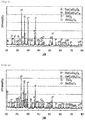
Fig.1 is a drawing which illustrates an XRD pattern of the phosphor (sample) obtained in Example 1. -
Fig.2 is a drawing which illustrates an XRD pattern of the phosphor (sample) obtained in Example 2. -
Fig.3 is a drawing which illustrates an XRD pattern of the phosphor (sample) obtained in Comparative Example 1. -
Fig.4 is a drawing which illustrates an XRD pattern of the phosphor (sample) obtained in Comparative Example 2. -
Fig.5 is a drawing which illustrates an XRD pattern of the phosphor (sample) obtained in Comparative Example 3. -
Fig.6 is a drawing which illustrates an XRD pattern of the phosphor (sample) obtained in Comparative Example 4. -
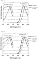
Fig.7 is a drawing which illustrates excitation spectra and fluorescence spectra of Example 1 and Comparative Example 1 as relative values when the maximum values of excitation intensity and fluorescence intensity in the vertical axis are normalized as 1. -
Fig.8 is a drawing which illustrates excitation spectra and fluorescence spectra of Example 1, Example 2 and Comparative Example 4 as relative values when the maximum values of excitation intensity and fluorescence intensity in the vertical axis are normalized as 1. -
Fig.9 is a drawing which compares excitation spectrum intensities to fluorescence spectrum intensities of Example 1, Example 2 and Comparative Example 4. - Next, the present invention will be described based on embodiments for carrying out the present invention. However, the present invention is not limited to the embodiments that will be described below.
- The phosphor according to an example of the present embodiment (referred to as "the present phosphor") is a phosphor containing at least a crystal phase represented by a formula (1) : MCuSi2O6 (where M comprises one or two or more of Ba, Sr and Ca) (referred to as "MCuSi2O6 crystal phase") and a crystal phase represented by a formula (2): MCuSi4O10 (where M comprises one or two or more of Ba, Sr and Ca) (referred to as "MCuSi4O10 crystal phase").
- By containing the MCuSi2O6 crystal phase and the MCuSi4O10 crystal phase, a band of an excitation spectrum can be expanded while maintaining fluorescence spectrum intensity.
- The present phosphor may be a polycrystal body comprising a plurality of crystal phases, or a mixture containing a plurality of crystal phases.
- Meanwhile, in a case of expressing the MCuSi2O6 crystal phase, when the "crystal phase" contains MCuSi2O6 as a main component, the "crystal phase" may also contain the other components, for example, a component present in a crystal phase, which cannot be detected by XRD. Same applies to another crystal phase.
- In the present phosphor, the MCuSi2O6 crystal phase is preferably a main crystal phase. In other words, in an X-ray diffraction (XRD) pattern obtained by powder XRD measurement using CuKα rays, it is preferable that a diffraction peak intensity derived from the crystal phase of MCuSi2O6 is larger than a diffraction peak intensity derived from any other crystal phases.
- Further, as for the present phosphor, in an X-ray diffraction (XRD) pattern obtained by measuring the present phosphor by powder XRD measurement using CuKα rays, a ratio β of a diffraction peak intensity of MCuSi4O10 with respect to a diffraction peak intensity of MCuSi2O6 is 0 < β ≤ 0.50.
- When containing MCuSi2O6 and MCuSi4O10 in such a range, a band of an excitation spectrum can be expanded while maintaining fluorescence spectrum intensity.
- From such points of view, it is preferable that a ratio β of a diffraction peak intensity of MCuSi4O10 with respect to a diffraction peak intensity of MCuSi2O6 is 0 < β ≤ 0.50. Among others, it is more preferably 0 < β ≤ 0.31, and furthermore preferably 0 < β ≤ 0.10.
- At this time, the content of each of the crystal phases is expressed by the diffraction peak intensity of each of the crystal phases in the XRD pattern, not by chemical analysis. This is because when the content of each of the crystal phases is represented by chemical analysis, it is largely affected by a blending amount of an additive such as flux, and thus the characteristics of the present phosphor are difficult to be expressed accurately. In contrast, when the content of each of the crystal phases is expressed by the diffraction peak intensity of each of the crystal phases in the XRD pattern, the effect by the blending amount of the additive can be suppressed, and thus the characteristics of the present phosphor can be expressed accurately.
- It is preferable that the present phosphor further contains a SiO2 crystal phase. However, the present phosphor may not contain the SiO2 crystal phase.
- When the present phosphor contains the SiO2 crystal phase, in an X-ray diffraction (XRD) pattern obtained by measuring the present phosphor by powder XRD measurement using CuKα rays, it is preferable that a ratio α of a diffraction peak intensity of SiO2 with respect to a diffraction peak intensity of MCuSi2O6 is 0 < a < 0.45. When containing the SiO2 crystal phase in such a range, scattering of excitation light can be prevented, and higher fluorescence spectrum intensity can be obtained.
- From such points of view, it is preferable that a ratio α of a diffraction peak intensity of SiO2 is 0 < α < 0.45, more preferably 0.16 < a, and even more preferably a < 0.35. Among others, it is particularly preferably α < 0.3, and furthermore preferably 0.20 < a or a < 0.25.
- Meanwhile, the present phosphor may contain, or may not contain a BaSi2O5 crystal phase. This is because, by containing the BaSi2O5 crystal phase, both an advantage and a disadvantage are not confirmed at the present time.
- In addition, it is preferable that a part of Cu in the formula (1) : MCuSi2O6 or the formula (2) : MCuSi4O10, or both the formulae is substituted by Mg or Zn, or both of these. This is because even when a part of Cu is substituted by Mg or Zn, or both of these, adverse effects such as obstruction of luminescence at a local structure of Cu (CuO4) can be suppressed. Further, this is because, by forming MgO4 or ZnO4 in the crystal structure, self-absorption of luminescence by adjacent CuO4 each other can be prevented, and thus an improvement of quantum efficiency can be expected.
- It is preferable that the present phosphor further contains one or two or more elements selected from a group consisting of Li, Na, K, B, P, F, Cl, Br and I. At this time, the contents of these elements are preferably 0.005 to 3% by mass. Among others, it is more preferably 0.008% by mass or more or 2% by mass or less, and even more preferably 0.01% by mass or more or 1% by mass or less.
- When the present phosphor contains these elements, luminescent peak intensity can be consequently enhanced. These elements can be added as a part of a sintering aid.
- The present phosphor may contain element components other than the above when the contents of the element components other than the above are less than 20% by mass. This is because, it can be considered that the characteristics of the present phosphor are not affected by the other element components in such an amount.
- The present phosphor is not limited to the forms such as a film shape, a plate shape and a particle shape. However, from a point of view of workability to a luminescent device-mounted unit or a printed matter to be used, the form of the present phosphor is preferably a particle shape.
- The present phosphor can be produced by the following production method. However, the production method of the present phosphor is not limited to the production method to be described below.
- The present phosphor can be obtained by mixing M element raw material in the formula (1): MCuSi2O6, Cu raw material, and silicon raw material, adding flux (sintering aid) if necessary, and calcining the mixture.
- In so doing, examples of the M element raw material may include an oxide of M elements (one or two or more elements of Ba, Sr and Ca), carbonate, nitrate, acetate, and the like.
- Examples of the Cu raw material may include an oxide of Cu, carbonate, sulfate, metal, and the like.
- Examples of the silicon raw material may include an oxide of silicon, carbide, nitride, silicon, and the like.
- Incidentally, from a point of view of keeping a divalent oxidation number of Cu, it is preferable that a reducing agent is not added.
- A blending ratio (molar ratio) of the M element raw material and the Cu raw material is preferably 1.5 : 1.0 to 0.8 : 1.0. Among others, it is more preferably 1.3 : 1.0 to 0.9 : 1.0, and even more preferably 1.2 : 1.0 to 1.0 : 1.0. In addition, a blending ratio (mass ratio) of the Cu raw material and the silicon raw material is preferably 1.0 : 2.0 to 1.0 : 5.0. Among others, it is more preferably 1.0 : 3.0 to 1.0 : 4.5, and even more preferably 1.0 : 3.5 to 1.0 : 4.2.
- By blending flux (sintering aid), a chemical reaction can be promoted, and thus unreacted substances can be reduced.
- Examples of the flux (sintering aid) may include a flux (sintering aid) containing one or two or more elements selected from a group consisting of Li, Na, K, B, P, F, Cl, Br and I. Among others, it is more preferably Li, Na, K, B, F, Cl, and the like.
- A blending amount (mass ratio) of the flux (sintering aid) is preferably 0.1 to 15% with respect to a total weight obtained by mixing the M element raw material, the Cu raw material and the silicon raw material. Among others, it is more preferably 1% or more or 10% or less, and even more preferably 2% or more or 7% or less.
- As for a calcination atmosphere, if it is not a reducing atmosphere, any atmosphere can be appropriately employed. For example, an inert gas atmosphere, an air atmosphere, an acidic atmosphere and the like can be employed.
- A calcination temperature may be 700 to 1,100°C. This is because when it is less than 700°C, a reaction is hardly progressed. In contrast, when it is 1,100°C or more, there is a possibility of melting.
- In addition, the calcination may be repeated several times. That is, for example, the first calcination is performed in a temperature range of 700 to 900°C, the calcined powder thus obtained is crushed, and then the second calcination can be also performed in a temperature range of 800 to 1,100°C.
- Further, the calcined powder is washed with an acidic solution such as water and hydrochloric acid after the first calcination, and then the second calcination can be also performed. By doing so, the blending amount of the sintering aid can be more appropriately adjusted to each calcination step, and thus the element contents of Li, Na, K, B, P, F, Cl, Br and I contained in the present phosphor which is a final product can be also easily controlled in an appropriate range.
- The present phosphor is excited by visible light, and can emit near-infrared light. That is, the present phosphor has characteristics of having an excitation spectrum in a visible light region (380 nm to 750 nm), and having a luminescent peak in a near-infrared region (750 nm to 2,500 nm).
- In addition, as one of the characteristics of the present phosphor, a point that an excitation band is wide can be cited. For example, an excitation band width of 80% or more of the maximum excitation intensity can be set to 90 nm or more, more preferably 100 nm or more, and even more preferably 150 nm or more.
- Further, by containing a crystal phase represented by MCuSi4O10, or a crystal phase such as cristobalite, tridymite and quartz, which is represented by SiO2, the present phosphor has a characteristic that a luminescent intensity in a near-infrared region can be further enhanced.
- For example, the present phosphor is mixed with an organic resin or an inorganic filler, for example, glass particles, a metal oxide or the like, and further a solvent, a dispersant or the like if necessary, coated and formed as a liquid composition, and then solidified via drying or/and curing. Thus, the present phosphor can be used as a form of a phosphor composition layer, a phosphor composition filler or the like.
- Since the present phosphor is excited by visible light, and can emit near-infrared light, the present phosphor can be used for a near-infrared luminescent device. By using the near-infrared luminescent device, the present phosphor can be suitably used as a phosphor constituting a luminescent device mounted on luminescent device mounted units such as a near-infrared spectrometer and an optical coherence tomography (OCT), as a wavelength conversion material constituting a light-receiving device mounted on light-receiving device mounted units such as a solar power generator, and as a phosphor which is contained in fluorescent paint used for a fluorescent paint printed matter or a printed matter having an image recognition part of near-infrared light luminescence.
- When the near-infrared luminescent device containing the present phosphor (referred to as "the present near-infrared luminescent device") is used for a spectrometer, the spectrometer can be used for an evaluation apparatus of biological objects, fruits and vegetables, or the like.
- In the spectrometer, the present phosphor is mounted as a wavelength conversion material of a near-infrared light source.
- In addition, when the light-receiving device containing the present phosphor is used for a solar power generator, a visible light component of sunlight can be converted into near-infrared light, and thus the power generation efficiency can be further enhanced.
- In a solar spectrometer, the present phosphor can be mounted as a wavelength conversion material on a light-receiving side. Particularly, it is known that a light-receiving device using a silicon photo-diode has high spectral sensitivity in a wavelength band of near-infrared light of 800 to 1,000 nm, and thus the present phosphor is suitable as a wavelength conversion material having an excellent matching property with 900 to 950 nm, which is a peak wavelength band of near-infrared luminescence of the present phosphor.
- Meanwhile, since the present phosphor emits near-infrared light even when electron rays, X-rays or the like are used as an excitation source, for example, when using X-rays as an excitation source, applications into an X-ray diagnostic apparatus for medical or security as a scintillation material, or the like are possible.
- Further, when a fluorescent paint is produced by using the present phosphor, for example, a fluorescent paint printed matter which is used for forgery-proof printing utilized for paper-money or the like can be produced, and then novel forgery-proof printing in which the forgery, which cannot be detected with the naked eye, can be detected by a solid-state imaging device using a photo-diode made of silicon, InGaAs or the like, or equipment using a photomultiplier tube, can be performed.
- These fluorescent paints are mixed with a fluidity adjusting material of inorganic components or organic components, an organic solvent, or the like, as setting transparent resin components as matrix in addition to the present phosphor, and prepared as ink or paste. Examples of the resin component may include an epoxy resin, a phenol resin, a silicone resin, an acrylic resin, and polymethyl methacrylate. Additionally, glass particles, which are light scattering components, may be mixed if necessary.
- In the present invention, when the term "X to Y" (X and Y are arbitrary numbers) is expressed, unless particularly stated otherwise, the expression includes the meaning of "X or more and Y or less", as well as the meaning of "preferably more than X" or "preferably less than Y".
- Further, when the term "X or more" (X is an arbitrary number) or "Y or less" (Y is an arbitrary number) is expressed, the expression includes the meaning of "more than X is preferable" or "less than Y is preferable".
- Hereafter, the present invention will be described in further detail based on the examples and comparative examples described below.
- Each of the phosphors (samples) obtained in Examples and Comparative Examples served as a sample for powder X-ray diffraction measurement (XRD). The sample was mounted on a holder, and angles and intensities of the diffracted rays were measured using MXP18 (manufactured by Bruker AXS) under the following conditions, thereby obtaining an XRD pattern.
- (Tube) Cu Kα ray
(Tube voltage) 40 kV
(Tube current) 150 mA
(Sampling interval) 0.02°
(Scanning speed) 4.0°/min
(Initiation angle) 5.02°
(Termination angle) 80° - Each of the phosphors (samples) obtained in Examples and Comparative Examples served as a sample for luminescent characteristic measurement, and an excitation spectrum and a fluorescence spectrum were measured using a spectrofluorometer (FP-8600, manufactured by JASCO Corp.) under conditions in which the band widths of both the excitation side and the fluorescence side were 10 nm and the scanning speed was 1,000 nm/min.
- The excitation spectrum was evaluated by the following criteria.
- A: an excitation band width of 80% or more of the maximum excitation intensity is 120 nm or more.
- B: an excitation band width of 80% or more of the maximum excitation intensity is 90 nm or more.
- C: an excitation band width of 80% or more of the maximum excitation intensity is less than 90 nm.
- Each of the fluorescence spectra in excitation wavelengths (620 nm, 570 nm and 520 nm) was evaluated by the following criteria.
- A: a peak intensity is 4,000 counts or more.
- B: a peak intensity is 3,000 counts or more and less than 4,000 counts.
- C: a peak intensity is less than 3,000 counts.
- (Overall evaluation)
- The four evaluation items, that is, the excitation band width of the evaluated excitation spectrum and the peak intensity of the fluorescence spectrum in each of the excitation wavelengths (620 nm, 570 nm and 520 nm), were evaluated by the following criteria.
- AA: the four evaluation items are all A.
- A: the four evaluation items are A or B, and the number of A is 2 or more.
- B: the four evaluation items are A or B, and the number of A is 1 or less.
- C: the number of C in the four evaluation items is 1 or more.
- BaCO3, CuO and SiO2 were mixed such that a molar ratio of those was 1 : 1 : 3.5. Further, BaCl2 as flux was added to the mixture such that the total amount of the mixture became 3% by mass, and was mixed. The mixture was put in an alumina crucible, and was calcined at 1,000°C for 24 hours under the air, thereby obtaining a phosphor (sample).
- An XRD pattern of the obtained phosphor (sample) is illustrated in
Fig.1 . - The obtained phosphor (sample) was a compound composed of a BaCuSi2O6 phase as a main crystal phase, and containing a SiO2 phase, a trace amount of BaCuSi4O10 phase, and a BaSi2O5 phase.
- A Cl amount contained in the compound was 0.02% by mass by the fluorescence X-ray measurement.
- BaCO3, CuO and SiO2 were mixed such that a molar ratio of those was 1 : 1 : 4. Further, BaCl2 as flux was added to the mixture such that the total amount of the mixture became 3% by mass, and was mixed. The mixture was put in an alumina crucible, and was calcined at 1,000°C for 24 hours under the air, thereby obtaining a phosphor (sample).
- An XRD pattern of the obtained phosphor (sample) is illustrated in
Fig.2 . - The obtained phosphor (sample) was a compound composed of a BaCuSi2O6 phase as a main crystal phase, and containing a SiO2 phase, a BaCuSi4O10 phase, and a BaSi2O5 phase.
- A Cl amount contained in the compound was 0.01% by mass by the fluorescence X-ray measurement.
- BaCO3, CuO and SiO2 were weighed such that a molar ratio of those was 1 : 1 : 4, and were wet mixed in acetone.
- The mixture was put in an alumina crucible, and was calcined at 960°C for 16 hours under the air, thereby obtaining a phosphor (sample).
- An XRD pattern of the obtained phosphor (sample) is illustrated in
Fig.3 . - The obtained phosphor (sample) was a single phase of BaCuSi4O10,
- Each of the contents of halogen elements such as Cl, alkaline metals such as Na, and P in the phosphor (sample) was less than 0.005% by mass by the fluorescence X-ray measurement.
- BaCO3, CuO and SiO2 were mixed such that a molar ratio of those was 1 : 1 : 2. Then, the mixture was put in an alumina crucible, and was calcined at 1,000°C for 24 hours under the air, thereby obtaining a phosphor (sample).
- An XRD pattern of the obtained phosphor (sample) is illustrated in
Fig.4 . - The obtained phosphor (sample) was a compound composed of a BaCuSi2O6 phase as a main crystal phase, and containing a trace amount of BaSi2O5 phase.
- Each of the contents of halogen elements such as Cl, alkaline metals such as Na, and P, which were contained in the compound, was less than 0.005% by mass by the fluorescence X-ray measurement.
- BaCO3, CuO and SiO2 were mixed such that a molar ratio of those was 1 : 1 : 3. Then, the mixture was put in an alumina crucible, and was calcined at 1,000°C for 24 hours under the air, thereby obtaining a phosphor (sample).
- An XRD pattern of the obtained phosphor (sample) is illustrated in
Fig.5 . - The obtained phosphor (sample) was a compound composed of a SiO2 phase as a main crystal phase, and containing a BaCuSi2O6 phase and a trace amount of BaSi2O5 phase.
- Each of the contents of halogen elements such as Cl, alkaline metals such as Na, and P, which were contained in the compound, was less than 0.005% by mass by the fluorescence X-ray measurement.
- BaCO3, Cu2CO3·(OH)2·H2O and SiO2 were mixed such that a molar ratio of those was 1 : 0.5 : 4, and were wet mixed in ethanol. The mixture was put in an alumina crucible, and was calcined at 1,100°C for 24 hours under the air, thereby obtaining a phosphor (sample).
- An XRD pattern of the obtained phosphor (sample) is illustrated in
Fig.6 . - The obtained phosphor (sample) was a compound composed of a BaCuSi4O10 phase and a BaCuSi2O6 phase as a main crystal phase, and containing a SiO2 phase and a BaSi2O5 phase.
- Each of the contents of halogen elements such as Cl, alkaline metals such as Na, and P, which were contained in the compound, was less than 0.005% by mass by the fluorescence X-ray measurement.
Crystal phase Fluorescence characteristics 1-1-2-6 phase BaCuSi206 1-1-4-10 phase BaCuSi4O10 0-0-1-2 phase SiO2 Peak intensity ratio α Peak intensity ratio β Excitation spectra Fluorescence spectra Overal evaluation SiO2 /BaCuSi2O6 BaCuSi4O10 /BaCuSi2O6 Excitation band width (nm) wavelength (nm) Peak intensity 620nm excitation Peak intensity 570nm excitation Peak intensity 520nm excitation Example 1 Contained Contained Contained 0.21 0.08 152 A 913 4440 A 4237 A 4000 A AA Example 2 Contained Contained Contained 0.31 0.31 94 B 928 5217 A 4137 A 3660 B A Comparative Example 1 None Contained None - - 67 C 948 - - - C Comparative Example 2 Contained None None 0 0 >156 A 906 1553 C 1642 C 1526 C C Comparative Example 3 Contained None Contained 0.45 0 >150 A 913 1345 C 1507 C 1446 C C Comparative Example 4 Contained Contained Contained 016 069 60 c 942 3483 B 2164 C 1810 C C -
Fig.7 is a drawing which illustrates excitation spectra and fluorescence spectra of Example 1 and Comparative Example 1 as relative values when the maximum values of excitation intensity and fluorescence intensity in the vertical axis are normalized as 1. - When focusing on the excitation spectra, Example 1 shows that wavelength dependency is small, and an intensity difference in a range of 500 nm to 650 nm falls within 20% or less. That is, if the excitation is made within a wavelength of this range, it is found that a fluorescent intensity difference can be suppressed within 20%, and the wavelength dependency is small. This shows that if a white light source or a plurality of single-color light sources is used, conversion efficiency to near-infrared light can be further enhanced.
- Meanwhile, in Comparative Example 1, dependency of an excitation wavelength is large, and an excitation wavelength band in which a fluorescent intensity difference can be suppressed within 20%, is limited to a narrow range of 615 to 680 nm. That is, a usable excitation light source is limited to a red light source, and the conversion efficiency to near-infrared light is suppressed low.
- Next, an effect of comprising the BaCuSi4O10 phase was studied.
-
Fig.8 is a drawing which illustrates excitation spectra and fluorescence spectra of Example 1, Example 2 and Comparative Example 4 when the maximum values of excitation intensity and fluorescence intensity in the vertical axis are normalized as 1. - When collating with the XRD patterns of each of Examples, it was found that wavelength dependency of the fluorescence spectrum was enlarged along with an increase of the BaCuSi4O10 phase. This is consistent even when considering the result of the BaCuSi4O10 single phase in Comparative Example 1.
-
Fig.9 is a drawing which compares excitation spectrum intensities to fluorescence spectrum intensities of Example 1, Example 2 and Comparative Example 4. - It is found that the spectrum intensities are from low to high in the order of Comparative Example 4 < Example 1 < Example 2. By comprising the BaCuSi4O10 phase intentionally while comprising the BaCuSi2O6 phase as a main crystal phase in the same manner as Example 2, it was found that excitation efficiency in a range of 580 to 700 nm was increased, and along with this, fluorescent intensity could be improved. However, when the amount of the BaCuSi4O10 phase is too large, it is also confirmed that the wavelength dependency of the excitation band tends to be strong.
- From the results of Examples as described above and the results of the various tests carried out by the inventors so far, when a ratio of the BaCuSi2O6 phase is increased, a band of the excitation spectrum is expanded. On the other hand, there is a tendency that the luminescent intensity is decreased. Thus, from a point of view of expanding the band of the excitation spectrum while maintaining the luminescent intensity, it is preferable to comprise an appropriate amount of the BaCuSi4O10 phase while comprising the BaCuSi2O6 phase as a main crystal phase. In other words, when a ratio of an intensity IB of a BaCuSi4O10 diffraction ray peak located in 2θ of 19.5 to 20.5° and an intensity IP of a BaCuSi2O6 diffraction ray peak located in 2θ of 23.5 to 24.5° is designated as an intensity ratio β (= IB / IP), it can be considered that a preferable range thereof is 0 < β ≤ 0.50, among them, more preferably 0 < β ≤ 0.31, and even more preferably 0 < β ≤ 0.10. In Example 1, it was β = 0.08.
- Next, an effect of comprising the SiO2 phase was studied.
- The excitation spectrum intensities and the fluorescence spectrum intensities of Example 1, Comparative Example 2 and 3 were compared (see Table 1).
- The spectrum intensities were from low to high in the order of Comparative Example 2 ≈ Comparative Example 3 < Example 1. In contrast, the contents of the SiO2 phase were from low to high in the order of Comparative Example 2 < Example 1 < Comparative Example 3.
- From the results of Examples as described above and the results of the various tests carried out by the inventors so far, there is no practical problem even when the SiO2 phase is not contained. On the other hand, in the case of containing the SiO2 phase, when a ratio of an intensity IS of a SiO2 diffraction ray peak located in 2θ of 20.6° to 21.1° and an intensity IP of a BaCuSi2O6 diffraction ray peak located in 2θ of 23.5 to 24.5° is designated as an intensity ratio α (= IS / IP), it can be considered that a preferable range thereof is 0 < α < 0.45, and among them, more preferably 0.1 < α or α < 0.3. In Example 1, it was α = 0.21.
- Incidentally, since a SiO2 main peak (near 2θ of 26.6°) is overlapped with a peak of BaCuSi2O6 (near 2θ of 27.1°), it was judged that the SiO2 main peak (near 2θ of 26.6°) was inappropriate to be used for the calculation of the intensity ratio.
- Since alkaline earth metals such as Ba, Sr and Ca have similar properties, even when using Sr or Ca instead of Ba, or with Ba, it can be considered that the same effect as the above Examples can be obtained.
Claims (8)
- A phosphor, comprising
a crystal phase represented by a formula (1): MCuSi2O6 (where M comprises one or two or more of Ba, Sr and Ca) and
a crystal phase represented by a formula (2): MCuSi4O10 (where M comprises one or two or more of Ba, Sr and Ca),
wherein, in an X-ray diffraction (XRD) pattern obtained by powder XRD measurement using CuKα rays, a ratio β of a diffraction peak intensity of MCuSi4O10 with respect to a diffraction peak intensity of MCuSi2O6 is 0 < β ≤ 0.50. - The phosphor according to claim 1, further comprising a SiO2 crystal phase,
wherein, in an X-ray diffraction (XRD) pattern obtained by powder XRD measurement using CuKα rays, a ratio α of a diffraction peak intensity of SiO2 with respect to a diffraction peak intensity of MCuSi2O6 is 0 < α < 0.45. - The phosphor according to claim 1 or 2, comprising a compound in which a part of Cu in the formula (1): MCuSi2O6 or the formula (2): MCuSi4O10, or both the formulae is substituted by Mg or Zn, or both of these.
- The phosphor according to any one of claims 1 to 3, further comprising one or two or more elements selected from a group consisting of Li, Na, K, B, P, F, Cl, Br and I at 0.005 to 3% by mass.
- A near-infrared luminescent device comprising the phosphor according to any one of claims 1 to 4.
- A unit comprising the near-infrared luminescent device according to claim 5.
- A fluorescent paint comprising the phosphor according to any one of claims 1 to 4.
- A phosphor printed matter using the fluorescent paint according to claim 7.
Applications Claiming Priority (2)
| Application Number | Priority Date | Filing Date | Title |
|---|---|---|---|
| JP2015040471 | 2015-03-02 | ||
| PCT/JP2016/053962 WO2016140029A1 (en) | 2015-03-02 | 2016-02-10 | Fluorophore |
Publications (3)
| Publication Number | Publication Date |
|---|---|
| EP3266849A1 true EP3266849A1 (en) | 2018-01-10 |
| EP3266849A4 EP3266849A4 (en) | 2018-08-01 |
| EP3266849B1 EP3266849B1 (en) | 2019-04-03 |
Family
ID=56849307
Family Applications (1)
| Application Number | Title | Priority Date | Filing Date |
|---|---|---|---|
| EP16758724.5A Active EP3266849B1 (en) | 2015-03-02 | 2016-02-10 | Fluorophore |
Country Status (6)
| Country | Link |
|---|---|
| US (1) | US10538679B2 (en) |
| EP (1) | EP3266849B1 (en) |
| JP (1) | JP6693942B2 (en) |
| KR (1) | KR101948593B1 (en) |
| CN (1) | CN107109218B (en) |
| WO (1) | WO2016140029A1 (en) |
Families Citing this family (8)
| Publication number | Priority date | Publication date | Assignee | Title |
|---|---|---|---|---|
| EP3431569B1 (en) | 2016-03-14 | 2020-12-16 | Mitsui Mining & Smelting Co., Ltd. | Fluorescent substance |
| WO2018143198A1 (en) * | 2017-01-31 | 2018-08-09 | 三菱ケミカル株式会社 | Light emitting device and fluorescent body |
| CN112262481B (en) * | 2018-06-12 | 2024-12-13 | 国立研究开发法人产业技术综合研究所 | Light-emitting device |
| DE102019122925A1 (en) * | 2018-08-29 | 2020-03-05 | Osa Opto Light Gmbh | Broadband emitter for electromagnetic radiation |
| CN113736460B (en) * | 2021-09-23 | 2023-07-21 | 五邑大学 | A kind of infrared fluorescent powder with high thermal stability and preparation method thereof |
| EP4745110A1 (en) * | 2023-07-14 | 2026-05-20 | Panasonic Ip Man Co Ltd | NEAR-INFRARED FLUORESCENT CERAMICS AND NEAR-INFRARED FLUORESCENT DEVICE WITH IT |
| CN117285337A (en) * | 2023-09-25 | 2023-12-26 | 深圳市亿万克数据设备科技有限公司 | Microwave dielectric materials and their preparation methods and applications |
| DE102025126198B3 (en) | 2025-07-04 | 2026-05-07 | Leuchtstoffwerk Breitungen Gmbh | Phosphorescent pigment material, methods for its production and its use |
Family Cites Families (7)
| Publication number | Priority date | Publication date | Assignee | Title |
|---|---|---|---|---|
| FR2716185B1 (en) * | 1994-02-11 | 1996-05-03 | Rhone Poulenc Chimie | Silicates based on alkaline earth, copper and possibly titanium, blue or purple pigments based on these silicates, their preparation process and their use. |
| EP1391015A4 (en) | 2001-05-03 | 2009-04-15 | Corning Inc | Broadband source with transition metal ions |
| JP4982751B2 (en) | 2007-01-29 | 2012-07-25 | 国立大学法人名古屋大学 | A light source for an optical coherence tomography apparatus composed of an infrared glass phosphor and a semiconductor light emitting element. |
| JP5295654B2 (en) | 2008-06-19 | 2013-09-18 | 本田技研工業株式会社 | Exhaust purification catalyst and exhaust purification apparatus using the same |
| JP5000028B2 (en) * | 2010-07-12 | 2012-08-15 | 国立大学法人名古屋大学 | Broadband infrared radiation equipment |
| CN104098103B (en) * | 2013-04-09 | 2017-11-24 | 中国科学技术大学 | A kind of " China is purple " and " Chinese blue " pigment tradition method for cooking |
| CN103601202B (en) * | 2013-11-14 | 2015-09-02 | 吉林大学 | Hydrothermal technique prepares SrCuSi 4o 10and BaCuSi 4o 10the method of blue pigments |
-
2016
- 2016-02-10 EP EP16758724.5A patent/EP3266849B1/en active Active
- 2016-02-10 CN CN201680004613.XA patent/CN107109218B/en active Active
- 2016-02-10 KR KR1020177012706A patent/KR101948593B1/en active Active
- 2016-02-10 JP JP2017503392A patent/JP6693942B2/en active Active
- 2016-02-10 WO PCT/JP2016/053962 patent/WO2016140029A1/en not_active Ceased
- 2016-02-10 US US15/533,057 patent/US10538679B2/en active Active
Also Published As
| Publication number | Publication date |
|---|---|
| KR20170069259A (en) | 2017-06-20 |
| CN107109218B (en) | 2020-03-10 |
| KR101948593B1 (en) | 2019-02-15 |
| EP3266849A4 (en) | 2018-08-01 |
| JP6693942B2 (en) | 2020-05-13 |
| CN107109218A (en) | 2017-08-29 |
| US20170335184A1 (en) | 2017-11-23 |
| EP3266849B1 (en) | 2019-04-03 |
| WO2016140029A1 (en) | 2016-09-09 |
| US10538679B2 (en) | 2020-01-21 |
| JPWO2016140029A1 (en) | 2017-12-14 |
Similar Documents
| Publication | Publication Date | Title |
|---|---|---|
| US10538679B2 (en) | Phosphor | |
| EP3431569B1 (en) | Fluorescent substance | |
| DE60224798T2 (en) | BROADBAND TERBIUM GRANITE FLUORES AND THEREFORE EQUIPPED WHITE LIGHT SOURCES | |
| JP7276534B2 (en) | Light-emitting device and phosphor | |
| CN112342021A (en) | A near-infrared broadband emission light-emitting material, its preparation method and light-emitting device comprising the material | |
| DE102015015355A1 (en) | Mn-activated phosphors | |
| Nakauchi et al. | Photoluminescence and scintillation properties of Eu-doped strontium aluminate crystals | |
| CZ304458B6 (en) | Inorganic scintillator or luminophore based on potassium-lutetium sulfide doped with europium (KLuS2:Eu) | |
| US8323530B2 (en) | Phosphor for scintillator | |
| EP3085752B1 (en) | Luminescent material comprising a strontium aluminate matrix | |
| KR20160133548A (en) | Europium or samarium-doped terbium molybdates | |
| CZ304998B6 (en) | Inorganic scintillators and luminophores based on ALnS2 (A = Na, K, Rb; Ln = La, Gd, Lu, Y) doped with Eu2+ with exception of KLuS2 and NaLaS2 | |
| EP4418335A1 (en) | Phosphor, light emitting device, lighting device, image display device and indicator lamp for vehicles | |
| JP2009120668A (en) | Colored structure | |
| US20230323201A1 (en) | Phosphor powder and light emitting device | |
| EP2985332B1 (en) | Up-conversion phosphor | |
| Rodriguez-Garcia | Synthesis and Characterisation of New Inorganic Silicate Luminescent Materials | |
| CN118401631A (en) | Phosphor and method for producing phosphor | |
| WO2022209033A1 (en) | Phosphor, method for producing same, light emitting element containing phosphor, and light emitting device | |
| JP2023049445A (en) | Phosphor, manufacturing method thereof, and light-emitting device | |
| WO2014167762A1 (en) | Phosphor and light-emitting device | |
| PL227690B1 (en) | Method for regulation of the colour of light emitted in the systems containing at least one matrix with optically active element in the form of the rare-earth ions-doped strontium cerate | |
| JP2018526471A (en) | Phosphor composition and lighting device thereof |
Legal Events
| Date | Code | Title | Description |
|---|---|---|---|
| STAA | Information on the status of an ep patent application or granted ep patent |
Free format text: STATUS: THE INTERNATIONAL PUBLICATION HAS BEEN MADE |
|
| PUAI | Public reference made under article 153(3) epc to a published international application that has entered the european phase |
Free format text: ORIGINAL CODE: 0009012 |
|
| STAA | Information on the status of an ep patent application or granted ep patent |
Free format text: STATUS: REQUEST FOR EXAMINATION WAS MADE |
|
| 17P | Request for examination filed |
Effective date: 20170601 |
|
| AK | Designated contracting states |
Kind code of ref document: A1 Designated state(s): AL AT BE BG CH CY CZ DE DK EE ES FI FR GB GR HR HU IE IS IT LI LT LU LV MC MK MT NL NO PL PT RO RS SE SI SK SM TR |
|
| AX | Request for extension of the european patent |
Extension state: BA ME |
|
| DAV | Request for validation of the european patent (deleted) | ||
| DAX | Request for extension of the european patent (deleted) | ||
| A4 | Supplementary search report drawn up and despatched |
Effective date: 20180629 |
|
| RIC1 | Information provided on ipc code assigned before grant |
Ipc: C09K 11/59 20060101AFI20180625BHEP Ipc: C09D 201/00 20060101ALI20180625BHEP |
|
| GRAP | Despatch of communication of intention to grant a patent |
Free format text: ORIGINAL CODE: EPIDOSNIGR1 |
|
| STAA | Information on the status of an ep patent application or granted ep patent |
Free format text: STATUS: GRANT OF PATENT IS INTENDED |
|
| RIC1 | Information provided on ipc code assigned before grant |
Ipc: C09D 201/00 20060101ALI20181025BHEP Ipc: C09D 7/61 20180101ALI20181025BHEP Ipc: C09D 1/00 20060101ALI20181025BHEP Ipc: A61B 5/00 20060101ALI20181025BHEP Ipc: C09K 11/59 20060101AFI20181025BHEP Ipc: C09D 5/22 20060101ALI20181025BHEP |
|
| INTG | Intention to grant announced |
Effective date: 20181130 |
|
| GRAS | Grant fee paid |
Free format text: ORIGINAL CODE: EPIDOSNIGR3 |
|
| RIC1 | Information provided on ipc code assigned before grant |
Ipc: C09D 201/00 20060101ALI20181025BHEP Ipc: C09D 5/22 20060101ALI20181025BHEP Ipc: C09K 11/59 20060101AFI20181025BHEP Ipc: C09D 1/00 20060101ALI20181025BHEP Ipc: C09D 7/61 20180101ALI20181025BHEP Ipc: A61B 5/00 20060101ALI20181025BHEP |
|
| RAP1 | Party data changed (applicant data changed or rights of an application transferred) |
Owner name: MITSUI MINING & SMELTING CO., LTD. |
|
| RIN1 | Information on inventor provided before grant (corrected) |
Inventor name: ITOH, JUN-ICHI Inventor name: OZAWA, IKUHIRO Inventor name: MORI, TAKAYOSHI |
|
| GRAA | (expected) grant |
Free format text: ORIGINAL CODE: 0009210 |
|
| STAA | Information on the status of an ep patent application or granted ep patent |
Free format text: STATUS: THE PATENT HAS BEEN GRANTED |
|
| AK | Designated contracting states |
Kind code of ref document: B1 Designated state(s): AL AT BE BG CH CY CZ DE DK EE ES FI FR GB GR HR HU IE IS IT LI LT LU LV MC MK MT NL NO PL PT RO RS SE SI SK SM TR |
|
| REG | Reference to a national code |
Ref country code: GB Ref legal event code: FG4D |
|
| REG | Reference to a national code |
Ref country code: CH Ref legal event code: EP Ref country code: AT Ref legal event code: REF Ref document number: 1115701 Country of ref document: AT Kind code of ref document: T Effective date: 20190415 |
|
| REG | Reference to a national code |
Ref country code: DE Ref legal event code: R096 Ref document number: 602016011999 Country of ref document: DE |
|
| REG | Reference to a national code |
Ref country code: IE Ref legal event code: FG4D |
|
| REG | Reference to a national code |
Ref country code: NL Ref legal event code: MP Effective date: 20190403 |
|
| REG | Reference to a national code |
Ref country code: LT Ref legal event code: MG4D |
|
| REG | Reference to a national code |
Ref country code: AT Ref legal event code: MK05 Ref document number: 1115701 Country of ref document: AT Kind code of ref document: T Effective date: 20190403 |
|
| PG25 | Lapsed in a contracting state [announced via postgrant information from national office to epo] |
Ref country code: NL Free format text: LAPSE BECAUSE OF FAILURE TO SUBMIT A TRANSLATION OF THE DESCRIPTION OR TO PAY THE FEE WITHIN THE PRESCRIBED TIME-LIMIT Effective date: 20190403 |
|
| PG25 | Lapsed in a contracting state [announced via postgrant information from national office to epo] |
Ref country code: HR Free format text: LAPSE BECAUSE OF FAILURE TO SUBMIT A TRANSLATION OF THE DESCRIPTION OR TO PAY THE FEE WITHIN THE PRESCRIBED TIME-LIMIT Effective date: 20190403 Ref country code: LT Free format text: LAPSE BECAUSE OF FAILURE TO SUBMIT A TRANSLATION OF THE DESCRIPTION OR TO PAY THE FEE WITHIN THE PRESCRIBED TIME-LIMIT Effective date: 20190403 Ref country code: SE Free format text: LAPSE BECAUSE OF FAILURE TO SUBMIT A TRANSLATION OF THE DESCRIPTION OR TO PAY THE FEE WITHIN THE PRESCRIBED TIME-LIMIT Effective date: 20190403 Ref country code: FI Free format text: LAPSE BECAUSE OF FAILURE TO SUBMIT A TRANSLATION OF THE DESCRIPTION OR TO PAY THE FEE WITHIN THE PRESCRIBED TIME-LIMIT Effective date: 20190403 Ref country code: CZ Free format text: LAPSE BECAUSE OF FAILURE TO SUBMIT A TRANSLATION OF THE DESCRIPTION OR TO PAY THE FEE WITHIN THE PRESCRIBED TIME-LIMIT Effective date: 20190403 Ref country code: AL Free format text: LAPSE BECAUSE OF FAILURE TO SUBMIT A TRANSLATION OF THE DESCRIPTION OR TO PAY THE FEE WITHIN THE PRESCRIBED TIME-LIMIT Effective date: 20190403 Ref country code: NO Free format text: LAPSE BECAUSE OF FAILURE TO SUBMIT A TRANSLATION OF THE DESCRIPTION OR TO PAY THE FEE WITHIN THE PRESCRIBED TIME-LIMIT Effective date: 20190703 Ref country code: PT Free format text: LAPSE BECAUSE OF FAILURE TO SUBMIT A TRANSLATION OF THE DESCRIPTION OR TO PAY THE FEE WITHIN THE PRESCRIBED TIME-LIMIT Effective date: 20190803 Ref country code: ES Free format text: LAPSE BECAUSE OF FAILURE TO SUBMIT A TRANSLATION OF THE DESCRIPTION OR TO PAY THE FEE WITHIN THE PRESCRIBED TIME-LIMIT Effective date: 20190403 |
|
| PG25 | Lapsed in a contracting state [announced via postgrant information from national office to epo] |
Ref country code: BG Free format text: LAPSE BECAUSE OF FAILURE TO SUBMIT A TRANSLATION OF THE DESCRIPTION OR TO PAY THE FEE WITHIN THE PRESCRIBED TIME-LIMIT Effective date: 20190703 Ref country code: GR Free format text: LAPSE BECAUSE OF FAILURE TO SUBMIT A TRANSLATION OF THE DESCRIPTION OR TO PAY THE FEE WITHIN THE PRESCRIBED TIME-LIMIT Effective date: 20190704 Ref country code: PL Free format text: LAPSE BECAUSE OF FAILURE TO SUBMIT A TRANSLATION OF THE DESCRIPTION OR TO PAY THE FEE WITHIN THE PRESCRIBED TIME-LIMIT Effective date: 20190403 Ref country code: LV Free format text: LAPSE BECAUSE OF FAILURE TO SUBMIT A TRANSLATION OF THE DESCRIPTION OR TO PAY THE FEE WITHIN THE PRESCRIBED TIME-LIMIT Effective date: 20190403 Ref country code: RS Free format text: LAPSE BECAUSE OF FAILURE TO SUBMIT A TRANSLATION OF THE DESCRIPTION OR TO PAY THE FEE WITHIN THE PRESCRIBED TIME-LIMIT Effective date: 20190403 |
|
| PG25 | Lapsed in a contracting state [announced via postgrant information from national office to epo] |
Ref country code: AT Free format text: LAPSE BECAUSE OF FAILURE TO SUBMIT A TRANSLATION OF THE DESCRIPTION OR TO PAY THE FEE WITHIN THE PRESCRIBED TIME-LIMIT Effective date: 20190403 Ref country code: IS Free format text: LAPSE BECAUSE OF FAILURE TO SUBMIT A TRANSLATION OF THE DESCRIPTION OR TO PAY THE FEE WITHIN THE PRESCRIBED TIME-LIMIT Effective date: 20190803 |
|
| REG | Reference to a national code |
Ref country code: DE Ref legal event code: R097 Ref document number: 602016011999 Country of ref document: DE |
|
| PG25 | Lapsed in a contracting state [announced via postgrant information from national office to epo] |
Ref country code: EE Free format text: LAPSE BECAUSE OF FAILURE TO SUBMIT A TRANSLATION OF THE DESCRIPTION OR TO PAY THE FEE WITHIN THE PRESCRIBED TIME-LIMIT Effective date: 20190403 Ref country code: DK Free format text: LAPSE BECAUSE OF FAILURE TO SUBMIT A TRANSLATION OF THE DESCRIPTION OR TO PAY THE FEE WITHIN THE PRESCRIBED TIME-LIMIT Effective date: 20190403 Ref country code: RO Free format text: LAPSE BECAUSE OF FAILURE TO SUBMIT A TRANSLATION OF THE DESCRIPTION OR TO PAY THE FEE WITHIN THE PRESCRIBED TIME-LIMIT Effective date: 20190403 Ref country code: SK Free format text: LAPSE BECAUSE OF FAILURE TO SUBMIT A TRANSLATION OF THE DESCRIPTION OR TO PAY THE FEE WITHIN THE PRESCRIBED TIME-LIMIT Effective date: 20190403 |
|
| PLBE | No opposition filed within time limit |
Free format text: ORIGINAL CODE: 0009261 |
|
| STAA | Information on the status of an ep patent application or granted ep patent |
Free format text: STATUS: NO OPPOSITION FILED WITHIN TIME LIMIT |
|
| PG25 | Lapsed in a contracting state [announced via postgrant information from national office to epo] |
Ref country code: SM Free format text: LAPSE BECAUSE OF FAILURE TO SUBMIT A TRANSLATION OF THE DESCRIPTION OR TO PAY THE FEE WITHIN THE PRESCRIBED TIME-LIMIT Effective date: 20190403 Ref country code: IT Free format text: LAPSE BECAUSE OF FAILURE TO SUBMIT A TRANSLATION OF THE DESCRIPTION OR TO PAY THE FEE WITHIN THE PRESCRIBED TIME-LIMIT Effective date: 20190403 |
|
| 26N | No opposition filed |
Effective date: 20200106 |
|
| PG25 | Lapsed in a contracting state [announced via postgrant information from national office to epo] |
Ref country code: TR Free format text: LAPSE BECAUSE OF FAILURE TO SUBMIT A TRANSLATION OF THE DESCRIPTION OR TO PAY THE FEE WITHIN THE PRESCRIBED TIME-LIMIT Effective date: 20190403 |
|
| PG25 | Lapsed in a contracting state [announced via postgrant information from national office to epo] |
Ref country code: SI Free format text: LAPSE BECAUSE OF FAILURE TO SUBMIT A TRANSLATION OF THE DESCRIPTION OR TO PAY THE FEE WITHIN THE PRESCRIBED TIME-LIMIT Effective date: 20190403 |
|
| REG | Reference to a national code |
Ref country code: CH Ref legal event code: PL |
|
| GBPC | Gb: european patent ceased through non-payment of renewal fee |
Effective date: 20200210 |
|
| REG | Reference to a national code |
Ref country code: BE Ref legal event code: MM Effective date: 20200229 |
|
| PG25 | Lapsed in a contracting state [announced via postgrant information from national office to epo] |
Ref country code: MC Free format text: LAPSE BECAUSE OF FAILURE TO SUBMIT A TRANSLATION OF THE DESCRIPTION OR TO PAY THE FEE WITHIN THE PRESCRIBED TIME-LIMIT Effective date: 20190403 Ref country code: LU Free format text: LAPSE BECAUSE OF NON-PAYMENT OF DUE FEES Effective date: 20200210 |
|
| PG25 | Lapsed in a contracting state [announced via postgrant information from national office to epo] |
Ref country code: CH Free format text: LAPSE BECAUSE OF NON-PAYMENT OF DUE FEES Effective date: 20200229 Ref country code: LI Free format text: LAPSE BECAUSE OF NON-PAYMENT OF DUE FEES Effective date: 20200229 |
|
| PG25 | Lapsed in a contracting state [announced via postgrant information from national office to epo] |
Ref country code: IE Free format text: LAPSE BECAUSE OF NON-PAYMENT OF DUE FEES Effective date: 20200210 Ref country code: GB Free format text: LAPSE BECAUSE OF NON-PAYMENT OF DUE FEES Effective date: 20200210 Ref country code: FR Free format text: LAPSE BECAUSE OF NON-PAYMENT OF DUE FEES Effective date: 20200229 |
|
| PG25 | Lapsed in a contracting state [announced via postgrant information from national office to epo] |
Ref country code: BE Free format text: LAPSE BECAUSE OF NON-PAYMENT OF DUE FEES Effective date: 20200229 |
|
| PG25 | Lapsed in a contracting state [announced via postgrant information from national office to epo] |
Ref country code: MT Free format text: LAPSE BECAUSE OF FAILURE TO SUBMIT A TRANSLATION OF THE DESCRIPTION OR TO PAY THE FEE WITHIN THE PRESCRIBED TIME-LIMIT Effective date: 20190403 Ref country code: CY Free format text: LAPSE BECAUSE OF FAILURE TO SUBMIT A TRANSLATION OF THE DESCRIPTION OR TO PAY THE FEE WITHIN THE PRESCRIBED TIME-LIMIT Effective date: 20190403 |
|
| PG25 | Lapsed in a contracting state [announced via postgrant information from national office to epo] |
Ref country code: MK Free format text: LAPSE BECAUSE OF FAILURE TO SUBMIT A TRANSLATION OF THE DESCRIPTION OR TO PAY THE FEE WITHIN THE PRESCRIBED TIME-LIMIT Effective date: 20190403 |
|
| REG | Reference to a national code |
Ref country code: DE Ref legal event code: R081 Ref document number: 602016011999 Country of ref document: DE Owner name: MITSUI KINZOKU COMPANY, LIMITED, JP Free format text: FORMER OWNER: MITSUI MINING & SMELTING CO., LTD., TOKYO, JP |
|
| PGFP | Annual fee paid to national office [announced via postgrant information from national office to epo] |
Ref country code: DE Payment date: 20251230 Year of fee payment: 11 |