EP3266691A1 - Front wheel hub inner steering structure of portable two-wheel vehicle - Google Patents
Front wheel hub inner steering structure of portable two-wheel vehicle Download PDFInfo
- Publication number
- EP3266691A1 EP3266691A1 EP16761007.0A EP16761007A EP3266691A1 EP 3266691 A1 EP3266691 A1 EP 3266691A1 EP 16761007 A EP16761007 A EP 16761007A EP 3266691 A1 EP3266691 A1 EP 3266691A1
- Authority
- EP
- European Patent Office
- Prior art keywords
- hub
- steering bearing
- steering
- fixed
- internal
- Prior art date
- Legal status (The legal status is an assumption and is not a legal conclusion. Google has not performed a legal analysis and makes no representation as to the accuracy of the status listed.)
- Granted
Links
Images

Classifications
-
- B—PERFORMING OPERATIONS; TRANSPORTING
- B62—LAND VEHICLES FOR TRAVELLING OTHERWISE THAN ON RAILS
- B62K—CYCLES; CYCLE FRAMES; CYCLE STEERING DEVICES; RIDER-OPERATED TERMINAL CONTROLS SPECIALLY ADAPTED FOR CYCLES; CYCLE AXLE SUSPENSIONS; CYCLE SIDECARS, FORECARS, OR THE LIKE
- B62K19/00—Cycle frames
- B62K19/30—Frame parts shaped to receive other cycle parts or accessories
- B62K19/32—Steering heads
-
- B—PERFORMING OPERATIONS; TRANSPORTING
- B60—VEHICLES IN GENERAL
- B60B—VEHICLE WHEELS; CASTORS; AXLES FOR WHEELS OR CASTORS; INCREASING WHEEL ADHESION
- B60B27/00—Hubs
- B60B27/0005—Hubs with ball bearings
-
- B—PERFORMING OPERATIONS; TRANSPORTING
- B60—VEHICLES IN GENERAL
- B60B—VEHICLE WHEELS; CASTORS; AXLES FOR WHEELS OR CASTORS; INCREASING WHEEL ADHESION
- B60B27/00—Hubs
- B60B27/02—Hubs adapted to be rotatably arranged on axle
- B60B27/023—Hubs adapted to be rotatably arranged on axle specially adapted for bicycles
-
- B—PERFORMING OPERATIONS; TRANSPORTING
- B62—LAND VEHICLES FOR TRAVELLING OTHERWISE THAN ON RAILS
- B62K—CYCLES; CYCLE FRAMES; CYCLE STEERING DEVICES; RIDER-OPERATED TERMINAL CONTROLS SPECIALLY ADAPTED FOR CYCLES; CYCLE AXLE SUSPENSIONS; CYCLE SIDECARS, FORECARS, OR THE LIKE
- B62K19/00—Cycle frames
- B62K19/30—Frame parts shaped to receive other cycle parts or accessories
- B62K19/36—Frame parts shaped to receive other cycle parts or accessories for attaching saddle pillars, e.g. adjustable during ride
-
- B—PERFORMING OPERATIONS; TRANSPORTING
- B62—LAND VEHICLES FOR TRAVELLING OTHERWISE THAN ON RAILS
- B62K—CYCLES; CYCLE FRAMES; CYCLE STEERING DEVICES; RIDER-OPERATED TERMINAL CONTROLS SPECIALLY ADAPTED FOR CYCLES; CYCLE AXLE SUSPENSIONS; CYCLE SIDECARS, FORECARS, OR THE LIKE
- B62K21/00—Steering devices
-
- B—PERFORMING OPERATIONS; TRANSPORTING
- B62—LAND VEHICLES FOR TRAVELLING OTHERWISE THAN ON RAILS
- B62K—CYCLES; CYCLE FRAMES; CYCLE STEERING DEVICES; RIDER-OPERATED TERMINAL CONTROLS SPECIALLY ADAPTED FOR CYCLES; CYCLE AXLE SUSPENSIONS; CYCLE SIDECARS, FORECARS, OR THE LIKE
- B62K21/00—Steering devices
- B62K21/005—Steering pivot axis arranged within the wheel, e.g. for a hub center steering arrangement
-
- B—PERFORMING OPERATIONS; TRANSPORTING
- B62—LAND VEHICLES FOR TRAVELLING OTHERWISE THAN ON RAILS
- B62K—CYCLES; CYCLE FRAMES; CYCLE STEERING DEVICES; RIDER-OPERATED TERMINAL CONTROLS SPECIALLY ADAPTED FOR CYCLES; CYCLE AXLE SUSPENSIONS; CYCLE SIDECARS, FORECARS, OR THE LIKE
- B62K21/00—Steering devices
- B62K21/06—Bearings specially adapted for steering heads
-
- B—PERFORMING OPERATIONS; TRANSPORTING
- B62—LAND VEHICLES FOR TRAVELLING OTHERWISE THAN ON RAILS
- B62K—CYCLES; CYCLE FRAMES; CYCLE STEERING DEVICES; RIDER-OPERATED TERMINAL CONTROLS SPECIALLY ADAPTED FOR CYCLES; CYCLE AXLE SUSPENSIONS; CYCLE SIDECARS, FORECARS, OR THE LIKE
- B62K21/00—Steering devices
- B62K21/12—Handlebars; Handlebar stems
-
- B—PERFORMING OPERATIONS; TRANSPORTING
- B62—LAND VEHICLES FOR TRAVELLING OTHERWISE THAN ON RAILS
- B62K—CYCLES; CYCLE FRAMES; CYCLE STEERING DEVICES; RIDER-OPERATED TERMINAL CONTROLS SPECIALLY ADAPTED FOR CYCLES; CYCLE AXLE SUSPENSIONS; CYCLE SIDECARS, FORECARS, OR THE LIKE
- B62K21/00—Steering devices
- B62K21/18—Connections between forks and handlebars or handlebar stems
Definitions
- the present invention relates to a steering structure, and more particularly to a front wheel hub steering structure of a portable two-wheeled vehicle.
- the direction control system of the two-wheeled vehicle mainly includes a steering shaft connected to the vehicle body at the front end of the vehicle body and a front fork mounted on the steering shaft.
- the steering is achieved by controlling the handlebars connected to the fork.
- the present invention provides an internal steering structure of a front wheel hub of a portable two-wheeled vehicle in view of the drawbacks of the prior art.
- the internal steering structure of the front wheel hub of the portable two-wheeled vehicle includes a front wheel mounted on the front end of the vehicle body of the two-wheeled vehicle, handlebars provided at the front end of the vehicle body of the two-wheeled vehicle, and a steering bearing sleeve vertically fixed to the front end of the vehicle body.
- the steering bearing sleeve is provided with a steering bearing fixing rod which is rotatable within the steering bearing sleeve.
- the steering bearing fixing rod is fixedly connected to the handlebars and is rotated synchronously with the handlebars.
- a rotatable front wheel is provided on the steering bearing fixing rod.
- the outer wall of the steering bearing sleeve is provided with at least one fixing member and fixedly connected to the front end of the vehicle body through the fixing member.
- the internal steering structure of the front wheel hub of the portable two-wheeled vehicle according to the present invention further includes a steering bearing, and the steering bearing fixing rod is rotatably mounted in the steering bearing sleeve through the steering bearing.
- the front wheel includes a fixed internal hub and an outer wheel rotatable relative to the fixed internal hub.
- the fixed internal hub is annular and the plane which the fixed internal hub is located coincides with the axis of the steering bearing fixing rod.
- a fixed mounting seat is provided on the fixed internal hub, and the fixed internal hub is fixedly mounted on the steering bearing fixing rod through the fixed mounting seat. Said handlebars are mounted on said fixed mount.
- the outer wheel includes an outer hub and a tire provided on the outer hub.
- the internal steering structure further comprises a rotary connecting device, and the outer hub is rotatably fitted to the outer ring of the fixed internal hub by the rotation coupling device.
- the rotary connection device includes a ball holder provided between the outer hub and the fixed internal hub, a plurality of balls is provided in the ball holder, and the balls are in rolling contact with the outer hub and the fixed hub, respectively.
- the middle of the fixed mounting seat is provided with a mounting hole, and the fixed hub is perforated through the mounting hole through bolts, so as to be fixedly mounted on said steering bearing fixing rod.
- the fixed mounting seat is provided with a mounting fixing hole at both ends thereof respectively, the ends of the handlebars have a left branch and a right branch, and the left and right branches are respectively mounted to a mounting fixing hole at both ends of the fixed mount by a fixing bolt.
- a space for rotation of the outer wheel is formed between the left branch and the right branch.
- the internal steering structure of the front wheel hub of the portable two-wheeled vehicle according to the present invention further comprises a steering bearing ring which is connected to the end of the steering bearing sleeve and is resistant to the steering bearing.
- the steering bearing sleeve fixed to the front end of the vehicle body and a steering bearing fixing rod rotatable in the steering bearing sleeve, and the inner hub and the handlebars are fixedly connected with the steering bearing fixing rod, the steering force balance is realized, the structure is simple and the operation is convenient, and the driving stability can be greatly improved.
- the internal steering structure of the front wheel hub of the portable two-wheeled vehicle is applicable to a two-wheeled vehicle having a small wheel type structure.
- the two-wheeled vehicle includes a front wheel mounted on the front end of the vehicle body 1 of a two-wheeled vehicle, handlebars 6 provided at the front end of the vehicle body 1 of the two-wheeled vehicle, and a steering bearing sleeve 2 vertically fixed to the front end of the vehicle body 1.
- at least one fixing member may be provided on the outer wall of the steering bearing bushing 2 and fixedly connected to the front end of the vehicle body 1 through the fixing member.
- the mounting screw hole 21 is provided in the outer wall of the steering bearing bushing 2, and the bolt 12 is inserted through the through hole 11 and screwed into the mounting screw hole 21, so that the steering bearing bushing 2 is fixedly mounted on the front end of the vehicle body 1.
- the steering bearing sleeve 2 is provided with a steering bearing fixing rod 4 which is rotatable within the steering bearing sleeve 2.
- the steering bearing fixing rod 4 is fixedly connected to the handlebars and is rotated synchronously with the handlebars.
- a steering bearing (The steering bearing may specifically include a steering bearing 22 and a steering bearing 23 provided at the lead-end and rear-end of the steering bearing fixing rod 4, respectively).
- the steering bearing fixing rod 4 is rotatably mounted in the steering bearing sleeve 2 through the steering bearing (i.e., the steering bearing 22, and the steering bearing 23).
- the steering bearing press ring may be provided and the steering bearing press ring is attached to the end of the steering bearing sleeve to withstand the steering bearing.
- two steering bearing presses 411, 412 are provided.
- the steering bearing press ring 411 and the steering bearing presser 412 are located at both ends of the steering bearing sleeve 2 and are respectively engaged with both ends of the steering bearing sleeve 2.
- the steering bearing presser 411 and the steering bearing presser 412 are engaged with the steering bearing bushings 2, their sides toward the inside of the steering sleeve 2 are against the steering bearing 22 and the diverter bearing 23, respectively.
- a rotatable front wheel is provided on the steering bearing fixing rod 4.
- the front wheel includes a fixed inner hub 3 and an outer wheel rotatable relative to the fixed inner hub 3.
- the fixed internal hub 3 is annular.
- the plane which the fixed internal hub 3 is located coincides with the axis of the steering bearing fixing rod 4. That is, the steering bearing fixing rod 4 is located in an annular region of the fixed internal hub 3 in parallel with the fixed internal hub 3.
- a fixed mounting seat 31 is provided on the fixed internal hub 3.
- the fixed internal hub 3 is fixed to the steering bearing fixing rod 4 through the fixed mounting seat 31. Said handlebars are mounted on said fixed mount 3.
- the outer ring may specifically include an outer hub 5 and a tire 51 provided on the outer hub 5.
- a rotary connecting device is further comprised, and the outer hub 5 is rotatably fitted to the outer ring of the fixed internal hub 3 by the rotation coupling device.
- the rotary connecting device specifically includes a roller frame 52 provided between the outer hub 5 and the fixed internal hub 3.
- a plurality of balls are provided in the ball holder 52, and the balls are in rolling contact with the outer hub 5 and the fixed internal hub 3, respectively.
- the middle portion of the fixed mounting seat 31 is provided with a mounting hole 312, and the fixed internal hub 3 is inserted through the mounting hole 312 via a bolt 311, so as to be fixedly mounted on the screw hole 413 of the steering bearing fixing rod 4.
- another mounting seat 314 may be provided on the opposite side of the fixed mounting seat 31 and connected to the other end of the steering bearing fixing rod 4 with the bolt 24 penetrating the mounting seat 314.
- a mounting fixing holes 313 is provided at both ends of the fixed mounting seat 31, respectively.
- the ends of the handlebars 6 have a left branch and a right branch (not shown), and the left and right branches are attached to the mounting fixing holes 313 at both ends of the fixing mount 31 by fixing bolts, respectively.
- a space for rotation of the outer wheel is formed between the left branch and the right branch, whereby the fixed internal hub 3 is fixed and the outer wheel is freely rotatable about the fixed internal hub 3.
Landscapes
- Engineering & Computer Science (AREA)
- Mechanical Engineering (AREA)
- Steering Devices For Bicycles And Motorcycles (AREA)
- Steering Controls (AREA)
- Steering-Linkage Mechanisms And Four-Wheel Steering (AREA)
Abstract
Description
- The present invention relates to a steering structure, and more particularly to a front wheel hub steering structure of a portable two-wheeled vehicle.
- In the prior art, the direction control system of the two-wheeled vehicle mainly includes a steering shaft connected to the vehicle body at the front end of the vehicle body and a front fork mounted on the steering shaft. The steering is achieved by controlling the handlebars connected to the fork.
- However, in the portable two-wheeled vehicles, such a structure has a lot of deficiencies, for example, the volume is too large to meet the two wheeler's portability needs. Or, in order to achieve the portability of the two wheels and the steering system is designed as part of the folding system, but this has brought the problem of instability in the direction of control, and there are driving safety risks.
- The present invention provides an internal steering structure of a front wheel hub of a portable two-wheeled vehicle in view of the drawbacks of the prior art.
- The internal steering structure of the front wheel hub of the portable two-wheeled vehicle according to the present invention includes a front wheel mounted on the front end of the vehicle body of the two-wheeled vehicle, handlebars provided at the front end of the vehicle body of the two-wheeled vehicle, and a steering bearing sleeve vertically fixed to the front end of the vehicle body.
- The steering bearing sleeve is provided with a steering bearing fixing rod which is rotatable within the steering bearing sleeve. The steering bearing fixing rod is fixedly connected to the handlebars and is rotated synchronously with the handlebars.
- A rotatable front wheel is provided on the steering bearing fixing rod.
- In the internal steering structure of the front wheel hub of the portable two-wheeled vehicle according to the present invention, the outer wall of the steering bearing sleeve is provided with at least one fixing member and fixedly connected to the front end of the vehicle body through the fixing member.
- The internal steering structure of the front wheel hub of the portable two-wheeled vehicle according to the present invention further includes a steering bearing, and the steering bearing fixing rod is rotatably mounted in the steering bearing sleeve through the steering bearing.
- In the internal steering structure of the front wheel hub of the portable two-wheeled vehicle according to the present invention, the front wheel includes a fixed internal hub and an outer wheel rotatable relative to the fixed internal hub.
- Wherein the fixed internal hub is annular and the plane which the fixed internal hub is located coincides with the axis of the steering bearing fixing rod.
- A fixed mounting seat is provided on the fixed internal hub, and the fixed internal hub is fixedly mounted on the steering bearing fixing rod through the fixed mounting seat. Said handlebars are mounted on said fixed mount.
- In the internal steering structure of the front wheel hub of the portable two-wheeled vehicle according to the present invention, the outer wheel includes an outer hub and a tire provided on the outer hub.
- The internal steering structure further comprises a rotary connecting device, and the outer hub is rotatably fitted to the outer ring of the fixed internal hub by the rotation coupling device.
- In the internal steering structure of the front wheel hub of the portable two-wheeled vehicle according to the present invention, the rotary connection device includes a ball holder provided between the outer hub and the fixed internal hub, a plurality of balls is provided in the ball holder, and the balls are in rolling contact with the outer hub and the fixed hub, respectively.
- In the internal steering structure of the front wheel hub of the portable two-wheeled vehicle according to the present invention, the middle of the fixed mounting seat is provided with a mounting hole, and the fixed hub is perforated through the mounting hole through bolts, so as to be fixedly mounted on said steering bearing fixing rod.
- The fixed mounting seat is provided with a mounting fixing hole at both ends thereof respectively, the ends of the handlebars have a left branch and a right branch, and the left and right branches are respectively mounted to a mounting fixing hole at both ends of the fixed mount by a fixing bolt.
- A space for rotation of the outer wheel is formed between the left branch and the right branch.
- The internal steering structure of the front wheel hub of the portable two-wheeled vehicle according to the present invention further comprises a steering bearing ring which is connected to the end of the steering bearing sleeve and is resistant to the steering bearing.
- In the internal steering structure of the front wheel hub of the portable two-wheeled vehicle according to the present invention, by providing a steering bearing sleeve fixed to the front end of the vehicle body and a steering bearing fixing rod rotatable in the steering bearing sleeve, and the inner hub and the handlebars are fixedly connected with the steering bearing fixing rod, the steering force balance is realized, the structure is simple and the operation is convenient, and the driving stability can be greatly improved.
-
-
Fig.1 is an exploded view of an internal steering structure of a front wheel hub of a portable two-wheeled vehicle according to the present invention; and -
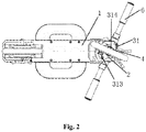
Fig.2 is a bottom view of the internal steering structure of the front wheel hub of the portable two-wheeled vehicle according to the present invention. - The present invention will now be described in further detail with reference to the accompanying drawings in order to enable those skilled in the art to practice with reference to the teachings.
- As shown in
Figs. 1 and2 , the internal steering structure of the front wheel hub of the portable two-wheeled vehicle according to the present invention is applicable to a two-wheeled vehicle having a small wheel type structure. The two-wheeled vehicle includes a front wheel mounted on the front end of thevehicle body 1 of a two-wheeled vehicle,handlebars 6 provided at the front end of thevehicle body 1 of the two-wheeled vehicle, and asteering bearing sleeve 2 vertically fixed to the front end of thevehicle body 1. In the present invention, at least one fixing member may be provided on the outer wall of the steering bearing bushing 2 and fixedly connected to the front end of thevehicle body 1 through the fixing member. In the present embodiment, four through-holes 11 are formed at the front end of thevehicle body 1, and the four through-holes 11 are equally divided on each side of the front end of thevehicle body 1. Correspondingly, themounting screw hole 21 is provided in the outer wall of the steering bearing bushing 2, and thebolt 12 is inserted through the throughhole 11 and screwed into themounting screw hole 21, so that thesteering bearing bushing 2 is fixedly mounted on the front end of thevehicle body 1. - In the present invention, the
steering bearing sleeve 2 is provided with a steering bearingfixing rod 4 which is rotatable within thesteering bearing sleeve 2. The steering bearingfixing rod 4 is fixedly connected to the handlebars and is rotated synchronously with the handlebars. In order to ensure a smoother rotation of the steering bearingfixing rod 4, in the present invention, a steering bearing (The steering bearing may specifically include a steering bearing 22 and a steering bearing 23 provided at the lead-end and rear-end of the steering bearingfixing rod 4, respectively). The steering bearingfixing rod 4 is rotatably mounted in thesteering bearing sleeve 2 through the steering bearing (i.e., the steering bearing 22, and the steering bearing 23). Further, the steering bearing press ring may be provided and the steering bearing press ring is attached to the end of the steering bearing sleeve to withstand the steering bearing. Specifically, in the present embodiment, twosteering bearing presses press ring 411 and the steering bearingpresser 412 are located at both ends of thesteering bearing sleeve 2 and are respectively engaged with both ends of thesteering bearing sleeve 2. When the steering bearing presser 411 and the steering bearingpresser 412 are engaged with thesteering bearing bushings 2, their sides toward the inside of thesteering sleeve 2 are against the steering bearing 22 and the diverter bearing 23, respectively. - In the present invention, a rotatable front wheel is provided on the steering bearing
fixing rod 4. Specifically, as shown inFig. 1 , the front wheel includes a fixed inner hub 3 and an outer wheel rotatable relative to the fixed inner hub 3. Wherein the fixed internal hub 3 is annular. The plane which the fixed internal hub 3 is located coincides with the axis of the steering bearingfixing rod 4. That is, the steering bearingfixing rod 4 is located in an annular region of the fixed internal hub 3 in parallel with the fixed internal hub 3. A fixedmounting seat 31 is provided on the fixed internal hub 3. The fixed internal hub 3 is fixed to the steering bearingfixing rod 4 through the fixedmounting seat 31. Said handlebars are mounted on said fixed mount 3. - In the present invention, the outer ring may specifically include an
outer hub 5 and atire 51 provided on theouter hub 5. A rotary connecting device is further comprised, and theouter hub 5 is rotatably fitted to the outer ring of the fixed internal hub 3 by the rotation coupling device. In the present embodiment, the rotary connecting device specifically includes aroller frame 52 provided between theouter hub 5 and the fixed internal hub 3. A plurality of balls (not shown in drawings) are provided in theball holder 52, and the balls are in rolling contact with theouter hub 5 and the fixed internal hub 3, respectively. By the roller and theball holder 52, theouter hub 5 is rotatable about the fixing hub 3 which is fixed. - In the present invention, the middle portion of the fixed
mounting seat 31 is provided with amounting hole 312, and the fixed internal hub 3 is inserted through themounting hole 312 via abolt 311, so as to be fixedly mounted on thescrew hole 413 of the steering bearingfixing rod 4. For the sake of stability, anothermounting seat 314 may be provided on the opposite side of the fixedmounting seat 31 and connected to the other end of the steering bearingfixing rod 4 with thebolt 24 penetrating themounting seat 314. - A
mounting fixing holes 313 is provided at both ends of the fixedmounting seat 31, respectively. The ends of thehandlebars 6 have a left branch and a right branch (not shown), and the left and right branches are attached to themounting fixing holes 313 at both ends of thefixing mount 31 by fixing bolts, respectively. A space for rotation of the outer wheel is formed between the left branch and the right branch, whereby the fixed internal hub 3 is fixed and the outer wheel is freely rotatable about the fixed internal hub 3. - While the embodiments of the present invention have been disclosed above, it is not limited to the use in the specification and the embodiments, it is entirely applicable to a variety of fields suitable for the present invention and is readily available to those skilled in the art. The present invention is not limited to the specific details and the illustrations shown herein and described herein without departing from the general concept as defined by the claims and the scope of equivalents.
Claims (8)
- An internal steering structure of a front wheel hub of a portable two-wheeled vehicle, comprising:a front wheel mounted on a front end of a vehicle body of the two-wheeled vehicle; andhandlebars provided at a front end of a vehicle body of a two-wheeled vehicle;characterized by further including a steering bearing sleeve that is vertically fixed to the front end of the vehicle body;wherein the steering bearing sleeve is provided with a steering bearing fixing rod which is rotatable within the steering bearing sleeve; wherein a steering bearing fixing rod is fixedly connected to the handlebars and is rotated synchronously with the handlebars; wherein a rotatable front wheel is provided on the steering bearing fixing rod.
- An internal steering structure of a front wheel hub of a portable two-wheeled vehicle according to claim 1, wherein the outer wall of the steering bearing sleeve is provided with at least one fixing member, and the steering bearing sleeve is fixedly connected to the front end of the vehicle body through the fixing member.
- An internal steering structure of a front wheel hub of a portable two-wheeled vehicle according to claim 1, further comprising a steering bearing, and a steering bearing fixing rod is rotatably mounted in the steering bearing sleeve through the steering bearing.
- An internal steering structure of a front wheel hub of a portable two-wheeled vehicle according to claim 1, wherein said front wheel includes a fixed internal hub and an outer wheel rotatable relative to said fixed hub;
wherein the fixed internal hub is annular and the plane which the fixed internal hub is located coincides with the axis of the steering bearing fixing rod;
wherein a fixed mounting seat is provided on the fixed internal hub, and the fixed internal hub is fixedly mounted on the steering bearing fixing rod through the fixed mounting seat, and said handlebars are mounted on said fixed mount. - An internal steering structure of a front wheel hub of a portable two-wheeled vehicle according to claim 4, wherein said outer wheel includes an outer hub and a tire disposed on said outer hub, and further including a rotary connecting device;
wherein the outer hub is rotatably fitted to the outer ring of the fixed internal hub by the rotation coupling device. - An internal steering structure of a front wheel hub of a portable two-wheeled vehicle according to claim 5,
wherein said rotary connecting means comprises:a ball holder provided between the outer hub and the fixed internal hub,a plurality of balls is provided in the frame, and the balls are in rolling contact with the outer hub and the fixed hub, respectively. - An internal steering structure of a front wheel hub of a portable two-wheeled vehicle according to claim 6, wherein a mounting hole is provided in a middle portion of the fixed mounting seat, and said fixed internal hub is perforated through said mounting hole via bolts, so that said fixed hub is fixedly mounted on said steering bearing fixing rod;
wherein the fixed mounting seat is provided with a mounting fixing hole at both ends thereof respectively, the ends of the handlebars have a left branch and a right branch, and the left and right branches are respectively mounted to a mounting fixing hole at both ends of the fixed mount by a fixing bolt;
wherein a space for rotation of the outer wheel is formed between the left branch and the right branch. - An internal steering structure of a front wheel hub of a portable two-wheeled vehicle according to claim 3, further comprising a steering bearing ring which is connected to the end of said steering bearing sleeve and is against the steering bearing.
Applications Claiming Priority (2)
| Application Number | Priority Date | Filing Date | Title |
|---|---|---|---|
| CN201510101084.2A CN104709421B (en) | 2015-03-06 | 2015-03-06 | Steering structure in a kind of front-wheel hub of portable two wheeler |
| PCT/CN2016/071716 WO2016141780A1 (en) | 2015-03-06 | 2016-01-22 | Front wheel hub inner steering structure of portable two-wheel vehicle |
Publications (3)
| Publication Number | Publication Date |
|---|---|
| EP3266691A1 true EP3266691A1 (en) | 2018-01-10 |
| EP3266691A4 EP3266691A4 (en) | 2018-12-19 |
| EP3266691B1 EP3266691B1 (en) | 2020-05-06 |
Family
ID=53409258
Family Applications (1)
| Application Number | Title | Priority Date | Filing Date |
|---|---|---|---|
| EP16761007.0A Not-in-force EP3266691B1 (en) | 2015-03-06 | 2016-01-22 | Front wheel hub inner steering structure of portable two-wheel vehicle |
Country Status (4)
| Country | Link |
|---|---|
| US (1) | US10377437B2 (en) |
| EP (1) | EP3266691B1 (en) |
| CN (1) | CN104709421B (en) |
| WO (1) | WO2016141780A1 (en) |
Families Citing this family (4)
| Publication number | Priority date | Publication date | Assignee | Title |
|---|---|---|---|---|
| CN104709421B (en) * | 2015-03-06 | 2017-07-18 | 周晓菲 | Steering structure in a kind of front-wheel hub of portable two wheeler |
| CN108357603A (en) * | 2018-03-02 | 2018-08-03 | 骅星科技发展有限公司 | A kind of stabilizer and Self-Balancing vehicle |
| CN110406314B (en) * | 2019-08-22 | 2024-02-06 | 永康骑客智能科技有限公司 | A hollow wheel body and a vehicle equipped with the wheel body |
| CN111017098B (en) * | 2019-12-18 | 2021-11-16 | 江西赛骑运动器械制造有限公司 | Bidirectional connection joint bearing steering system |
Family Cites Families (24)
| Publication number | Priority date | Publication date | Assignee | Title |
|---|---|---|---|---|
| JP2691724B2 (en) * | 1988-03-18 | 1997-12-17 | 本田技研工業株式会社 | Vehicle wheel, suspension device and steering device using the wheel |
| EP0393218B1 (en) * | 1989-04-19 | 1994-07-06 | Emco Maier Gesellschaft M.B.H. | Motorcycle frame |
| DE4126761A1 (en) * | 1991-08-13 | 1993-02-18 | Wilhelm Karl Beirlein Fa | MOTORCYCLE WITH A JOURNAL |
| US5201242A (en) * | 1992-04-24 | 1993-04-13 | Chi Yi C | Coupling for supporting a front fork in the head tube of a bicycle |
| JPH07101373A (en) * | 1993-10-05 | 1995-04-18 | Marui:Kk | Fixing structure for handle stem for bicycle |
| US5647684A (en) * | 1995-05-16 | 1997-07-15 | Chen; Chia-Ching | Two-step and toothless bicycle head shaft bowl set |
| US5810380A (en) * | 1996-08-23 | 1998-09-22 | Lin; Wen-Hwa | Bicycle front fork packing structure |
| US5979925A (en) * | 1998-04-02 | 1999-11-09 | Lin; Wen-Hwa | Bicycle head tube packing arrangement |
| WO2002022428A2 (en) * | 2000-09-16 | 2002-03-21 | Michael Prinz | Improved suspension of steered wheels for vehicles, especially scooters guided by weight transfer |
| US6322092B1 (en) * | 2000-12-28 | 2001-11-27 | Melton International, Llc | Structure for a steering spindle securing device |
| US6581492B1 (en) * | 2002-01-28 | 2003-06-24 | Far Great Plastics Industrial Co., Ltd. | Handle folding structure for a foldable bicycle |
| CN2567133Y (en) * | 2002-09-15 | 2003-08-20 | 周游 | Steering device in front axle of motorcycle |
| CN100465055C (en) * | 2005-12-19 | 2009-03-04 | 佳得车业有限公司 | Detachable front fork device for bicycle |
| FR2954266B1 (en) * | 2009-12-21 | 2011-12-23 | Look Cycle Int | CYCLE DIRECTION SET WITH PIN AND CYCLE COMPRISING SUCH A STEERING GAME |
| US7954831B1 (en) * | 2010-03-02 | 2011-06-07 | Ching-Ho Yeh | Scooter having a collapsible structure |
| CN201604774U (en) * | 2010-03-18 | 2010-10-13 | 叶嘉 | Two-wheeled bicycle |
| FR2968266B1 (en) * | 2010-12-02 | 2012-12-21 | Jacques Benarrouch | FOLDING TRIPTYQUE TROTTINETTE WITH REMOVABLE WHEELS |
| US8613457B2 (en) * | 2011-03-11 | 2013-12-24 | Andreas C. Wegener | Scooter assemblies and scooter deck assemblies |
| US8998224B2 (en) * | 2011-10-05 | 2015-04-07 | Rexco Industrial Ltd. | Scooter |
| EP2604497A1 (en) * | 2011-12-14 | 2013-06-19 | Mondo S.p.A. | Scooter |
| CN202764597U (en) * | 2012-09-18 | 2013-03-06 | 安徽安凯福田曙光车桥有限公司 | Wheel hub assembly installed on whole disk type front axle |
| DE102013207517B4 (en) * | 2013-04-25 | 2016-12-29 | Michael Schäfer | TAX SUSPENSION |
| EP3181436B1 (en) * | 2014-06-20 | 2019-09-18 | Yan, Kexue | Leisure sports scooter |
| CN104709421B (en) * | 2015-03-06 | 2017-07-18 | 周晓菲 | Steering structure in a kind of front-wheel hub of portable two wheeler |
-
2015
- 2015-03-06 CN CN201510101084.2A patent/CN104709421B/en not_active Expired - Fee Related
-
2016
- 2016-01-22 WO PCT/CN2016/071716 patent/WO2016141780A1/en not_active Ceased
- 2016-01-22 EP EP16761007.0A patent/EP3266691B1/en not_active Not-in-force
- 2016-01-22 US US15/563,572 patent/US10377437B2/en not_active Expired - Fee Related
Also Published As
| Publication number | Publication date |
|---|---|
| US20180086409A1 (en) | 2018-03-29 |
| EP3266691A4 (en) | 2018-12-19 |
| CN104709421A (en) | 2015-06-17 |
| WO2016141780A1 (en) | 2016-09-15 |
| CN104709421B (en) | 2017-07-18 |
| US10377437B2 (en) | 2019-08-13 |
| EP3266691B1 (en) | 2020-05-06 |
Similar Documents
| Publication | Publication Date | Title |
|---|---|---|
| US9896146B2 (en) | Two-axle vehicle balance scooter | |
| US9493205B2 (en) | Tricycle with foldable double-wheel assembly | |
| US10377437B2 (en) | Internal steering structure of a front wheel hub of a portable two-wheeled vehicle | |
| US10011316B2 (en) | Vehicle with foldable double-wheel assembly | |
| US10583690B2 (en) | Installation structure for wheel axle assembly and wheel fork, frame and vehicle | |
| US20160304149A1 (en) | Tricycle with two riding modes | |
| CN103158811A (en) | Scooter | |
| CN205239800U (en) | Children's money light double round balance car | |
| CN204870372U (en) | Wheel rotating -structure | |
| EP2543579A1 (en) | Head tube assembly for a bicycle with cable access routing in an open steerer configuration | |
| CN202641974U (en) | Three-point wheeled car with steering balancer | |
| CN204587155U (en) | Three-wheel scooter | |
| CN203318590U (en) | Differential right three-wheeled lying cycle with electric auxiliary power | |
| KR100994394B1 (en) | Tricycle | |
| US20120211964A1 (en) | Foldable bicycle with a large wheel and a small wheel | |
| CN207328688U (en) | A kind of modified rear axle for quadricycle | |
| CN203078703U (en) | C-shaped rod rolling friction power three-wheel scooter | |
| CN104058046B (en) | The adapter of conjuncted balance car | |
| CN103057642A (en) | C-bar rolling-friction-powered two-wheel scooter | |
| KR101765953B1 (en) | Knuckle structure | |
| CN203172830U (en) | C-shaped rod rolling friction force two-wheel scooter | |
| KR101648397B1 (en) | Reverse steering bicycle | |
| CN207267501U (en) | A kind of detachable automobile steering yoke | |
| CN201045043Y (en) | Wheel steering device for baby carriage | |
| CN203402341U (en) | Steering bracket of electric folding bicycle |
Legal Events
| Date | Code | Title | Description |
|---|---|---|---|
| STAA | Information on the status of an ep patent application or granted ep patent |
Free format text: STATUS: THE INTERNATIONAL PUBLICATION HAS BEEN MADE |
|
| PUAI | Public reference made under article 153(3) epc to a published international application that has entered the european phase |
Free format text: ORIGINAL CODE: 0009012 |
|
| STAA | Information on the status of an ep patent application or granted ep patent |
Free format text: STATUS: REQUEST FOR EXAMINATION WAS MADE |
|
| 17P | Request for examination filed |
Effective date: 20171005 |
|
| AK | Designated contracting states |
Kind code of ref document: A1 Designated state(s): AL AT BE BG CH CY CZ DE DK EE ES FI FR GB GR HR HU IE IS IT LI LT LU LV MC MK MT NL NO PL PT RO RS SE SI SK SM TR |
|
| AX | Request for extension of the european patent |
Extension state: BA ME |
|
| DAV | Request for validation of the european patent (deleted) | ||
| DAX | Request for extension of the european patent (deleted) | ||
| A4 | Supplementary search report drawn up and despatched |
Effective date: 20181115 |
|
| RIC1 | Information provided on ipc code assigned before grant |
Ipc: B62K 21/00 20060101ALI20181109BHEP Ipc: B62K 21/18 20060101ALI20181109BHEP Ipc: B62K 21/06 20060101AFI20181109BHEP |
|
| RIC1 | Information provided on ipc code assigned before grant |
Ipc: B62K 21/06 20060101AFI20191031BHEP Ipc: B62K 21/18 20060101ALI20191031BHEP Ipc: B62K 21/00 20060101ALI20191031BHEP |
|
| GRAP | Despatch of communication of intention to grant a patent |
Free format text: ORIGINAL CODE: EPIDOSNIGR1 |
|
| STAA | Information on the status of an ep patent application or granted ep patent |
Free format text: STATUS: GRANT OF PATENT IS INTENDED |
|
| INTG | Intention to grant announced |
Effective date: 20200114 |
|
| GRAS | Grant fee paid |
Free format text: ORIGINAL CODE: EPIDOSNIGR3 |
|
| GRAA | (expected) grant |
Free format text: ORIGINAL CODE: 0009210 |
|
| STAA | Information on the status of an ep patent application or granted ep patent |
Free format text: STATUS: THE PATENT HAS BEEN GRANTED |
|
| AK | Designated contracting states |
Kind code of ref document: B1 Designated state(s): AL AT BE BG CH CY CZ DE DK EE ES FI FR GB GR HR HU IE IS IT LI LT LU LV MC MK MT NL NO PL PT RO RS SE SI SK SM TR |
|
| REG | Reference to a national code |
Ref country code: GB Ref legal event code: FG4D |
|
| REG | Reference to a national code |
Ref country code: AT Ref legal event code: REF Ref document number: 1266319 Country of ref document: AT Kind code of ref document: T Effective date: 20200515 Ref country code: CH Ref legal event code: EP |
|
| REG | Reference to a national code |
Ref country code: IE Ref legal event code: FG4D |
|
| REG | Reference to a national code |
Ref country code: DE Ref legal event code: R096 Ref document number: 602016035867 Country of ref document: DE |
|
| REG | Reference to a national code |
Ref country code: LT Ref legal event code: MG4D |
|
| REG | Reference to a national code |
Ref country code: NL Ref legal event code: MP Effective date: 20200506 |
|
| PG25 | Lapsed in a contracting state [announced via postgrant information from national office to epo] |
Ref country code: PT Free format text: LAPSE BECAUSE OF FAILURE TO SUBMIT A TRANSLATION OF THE DESCRIPTION OR TO PAY THE FEE WITHIN THE PRESCRIBED TIME-LIMIT Effective date: 20200907 Ref country code: NO Free format text: LAPSE BECAUSE OF FAILURE TO SUBMIT A TRANSLATION OF THE DESCRIPTION OR TO PAY THE FEE WITHIN THE PRESCRIBED TIME-LIMIT Effective date: 20200806 Ref country code: GR Free format text: LAPSE BECAUSE OF FAILURE TO SUBMIT A TRANSLATION OF THE DESCRIPTION OR TO PAY THE FEE WITHIN THE PRESCRIBED TIME-LIMIT Effective date: 20200807 Ref country code: IS Free format text: LAPSE BECAUSE OF FAILURE TO SUBMIT A TRANSLATION OF THE DESCRIPTION OR TO PAY THE FEE WITHIN THE PRESCRIBED TIME-LIMIT Effective date: 20200906 Ref country code: SE Free format text: LAPSE BECAUSE OF FAILURE TO SUBMIT A TRANSLATION OF THE DESCRIPTION OR TO PAY THE FEE WITHIN THE PRESCRIBED TIME-LIMIT Effective date: 20200506 Ref country code: LT Free format text: LAPSE BECAUSE OF FAILURE TO SUBMIT A TRANSLATION OF THE DESCRIPTION OR TO PAY THE FEE WITHIN THE PRESCRIBED TIME-LIMIT Effective date: 20200506 Ref country code: FI Free format text: LAPSE BECAUSE OF FAILURE TO SUBMIT A TRANSLATION OF THE DESCRIPTION OR TO PAY THE FEE WITHIN THE PRESCRIBED TIME-LIMIT Effective date: 20200506 |
|
| PG25 | Lapsed in a contracting state [announced via postgrant information from national office to epo] |
Ref country code: BG Free format text: LAPSE BECAUSE OF FAILURE TO SUBMIT A TRANSLATION OF THE DESCRIPTION OR TO PAY THE FEE WITHIN THE PRESCRIBED TIME-LIMIT Effective date: 20200806 Ref country code: LV Free format text: LAPSE BECAUSE OF FAILURE TO SUBMIT A TRANSLATION OF THE DESCRIPTION OR TO PAY THE FEE WITHIN THE PRESCRIBED TIME-LIMIT Effective date: 20200506 Ref country code: RS Free format text: LAPSE BECAUSE OF FAILURE TO SUBMIT A TRANSLATION OF THE DESCRIPTION OR TO PAY THE FEE WITHIN THE PRESCRIBED TIME-LIMIT Effective date: 20200506 Ref country code: HR Free format text: LAPSE BECAUSE OF FAILURE TO SUBMIT A TRANSLATION OF THE DESCRIPTION OR TO PAY THE FEE WITHIN THE PRESCRIBED TIME-LIMIT Effective date: 20200506 |
|
| REG | Reference to a national code |
Ref country code: AT Ref legal event code: MK05 Ref document number: 1266319 Country of ref document: AT Kind code of ref document: T Effective date: 20200506 |
|
| PG25 | Lapsed in a contracting state [announced via postgrant information from national office to epo] |
Ref country code: AL Free format text: LAPSE BECAUSE OF FAILURE TO SUBMIT A TRANSLATION OF THE DESCRIPTION OR TO PAY THE FEE WITHIN THE PRESCRIBED TIME-LIMIT Effective date: 20200506 Ref country code: NL Free format text: LAPSE BECAUSE OF FAILURE TO SUBMIT A TRANSLATION OF THE DESCRIPTION OR TO PAY THE FEE WITHIN THE PRESCRIBED TIME-LIMIT Effective date: 20200506 |
|
| PG25 | Lapsed in a contracting state [announced via postgrant information from national office to epo] |
Ref country code: CZ Free format text: LAPSE BECAUSE OF FAILURE TO SUBMIT A TRANSLATION OF THE DESCRIPTION OR TO PAY THE FEE WITHIN THE PRESCRIBED TIME-LIMIT Effective date: 20200506 Ref country code: AT Free format text: LAPSE BECAUSE OF FAILURE TO SUBMIT A TRANSLATION OF THE DESCRIPTION OR TO PAY THE FEE WITHIN THE PRESCRIBED TIME-LIMIT Effective date: 20200506 Ref country code: RO Free format text: LAPSE BECAUSE OF FAILURE TO SUBMIT A TRANSLATION OF THE DESCRIPTION OR TO PAY THE FEE WITHIN THE PRESCRIBED TIME-LIMIT Effective date: 20200506 Ref country code: IT Free format text: LAPSE BECAUSE OF FAILURE TO SUBMIT A TRANSLATION OF THE DESCRIPTION OR TO PAY THE FEE WITHIN THE PRESCRIBED TIME-LIMIT Effective date: 20200506 Ref country code: DK Free format text: LAPSE BECAUSE OF FAILURE TO SUBMIT A TRANSLATION OF THE DESCRIPTION OR TO PAY THE FEE WITHIN THE PRESCRIBED TIME-LIMIT Effective date: 20200506 Ref country code: EE Free format text: LAPSE BECAUSE OF FAILURE TO SUBMIT A TRANSLATION OF THE DESCRIPTION OR TO PAY THE FEE WITHIN THE PRESCRIBED TIME-LIMIT Effective date: 20200506 Ref country code: SM Free format text: LAPSE BECAUSE OF FAILURE TO SUBMIT A TRANSLATION OF THE DESCRIPTION OR TO PAY THE FEE WITHIN THE PRESCRIBED TIME-LIMIT Effective date: 20200506 Ref country code: ES Free format text: LAPSE BECAUSE OF FAILURE TO SUBMIT A TRANSLATION OF THE DESCRIPTION OR TO PAY THE FEE WITHIN THE PRESCRIBED TIME-LIMIT Effective date: 20200506 |
|
| REG | Reference to a national code |
Ref country code: DE Ref legal event code: R097 Ref document number: 602016035867 Country of ref document: DE |
|
| PG25 | Lapsed in a contracting state [announced via postgrant information from national office to epo] |
Ref country code: SK Free format text: LAPSE BECAUSE OF FAILURE TO SUBMIT A TRANSLATION OF THE DESCRIPTION OR TO PAY THE FEE WITHIN THE PRESCRIBED TIME-LIMIT Effective date: 20200506 Ref country code: PL Free format text: LAPSE BECAUSE OF FAILURE TO SUBMIT A TRANSLATION OF THE DESCRIPTION OR TO PAY THE FEE WITHIN THE PRESCRIBED TIME-LIMIT Effective date: 20200506 |
|
| PLBE | No opposition filed within time limit |
Free format text: ORIGINAL CODE: 0009261 |
|
| STAA | Information on the status of an ep patent application or granted ep patent |
Free format text: STATUS: NO OPPOSITION FILED WITHIN TIME LIMIT |
|
| 26N | No opposition filed |
Effective date: 20210209 |
|
| PGFP | Annual fee paid to national office [announced via postgrant information from national office to epo] |
Ref country code: FR Payment date: 20210125 Year of fee payment: 6 |
|
| PG25 | Lapsed in a contracting state [announced via postgrant information from national office to epo] |
Ref country code: SI Free format text: LAPSE BECAUSE OF FAILURE TO SUBMIT A TRANSLATION OF THE DESCRIPTION OR TO PAY THE FEE WITHIN THE PRESCRIBED TIME-LIMIT Effective date: 20200506 |
|
| PGFP | Annual fee paid to national office [announced via postgrant information from national office to epo] |
Ref country code: DE Payment date: 20210128 Year of fee payment: 6 Ref country code: GB Payment date: 20210127 Year of fee payment: 6 |
|
| PG25 | Lapsed in a contracting state [announced via postgrant information from national office to epo] |
Ref country code: MC Free format text: LAPSE BECAUSE OF FAILURE TO SUBMIT A TRANSLATION OF THE DESCRIPTION OR TO PAY THE FEE WITHIN THE PRESCRIBED TIME-LIMIT Effective date: 20200506 |
|
| REG | Reference to a national code |
Ref country code: CH Ref legal event code: PL |
|
| PG25 | Lapsed in a contracting state [announced via postgrant information from national office to epo] |
Ref country code: LU Free format text: LAPSE BECAUSE OF NON-PAYMENT OF DUE FEES Effective date: 20210122 |
|
| REG | Reference to a national code |
Ref country code: BE Ref legal event code: MM Effective date: 20210131 |
|
| PG25 | Lapsed in a contracting state [announced via postgrant information from national office to epo] |
Ref country code: CH Free format text: LAPSE BECAUSE OF NON-PAYMENT OF DUE FEES Effective date: 20210131 Ref country code: LI Free format text: LAPSE BECAUSE OF NON-PAYMENT OF DUE FEES Effective date: 20210131 |
|
| PG25 | Lapsed in a contracting state [announced via postgrant information from national office to epo] |
Ref country code: IE Free format text: LAPSE BECAUSE OF NON-PAYMENT OF DUE FEES Effective date: 20210122 |
|
| PG25 | Lapsed in a contracting state [announced via postgrant information from national office to epo] |
Ref country code: BE Free format text: LAPSE BECAUSE OF NON-PAYMENT OF DUE FEES Effective date: 20210131 |
|
| REG | Reference to a national code |
Ref country code: DE Ref legal event code: R119 Ref document number: 602016035867 Country of ref document: DE |
|
| GBPC | Gb: european patent ceased through non-payment of renewal fee |
Effective date: 20220122 |
|
| PG25 | Lapsed in a contracting state [announced via postgrant information from national office to epo] |
Ref country code: GB Free format text: LAPSE BECAUSE OF NON-PAYMENT OF DUE FEES Effective date: 20220122 Ref country code: DE Free format text: LAPSE BECAUSE OF NON-PAYMENT OF DUE FEES Effective date: 20220802 |
|
| PG25 | Lapsed in a contracting state [announced via postgrant information from national office to epo] |
Ref country code: FR Free format text: LAPSE BECAUSE OF NON-PAYMENT OF DUE FEES Effective date: 20220131 |
|
| PG25 | Lapsed in a contracting state [announced via postgrant information from national office to epo] |
Ref country code: CY Free format text: LAPSE BECAUSE OF FAILURE TO SUBMIT A TRANSLATION OF THE DESCRIPTION OR TO PAY THE FEE WITHIN THE PRESCRIBED TIME-LIMIT Effective date: 20200506 |
|
| PG25 | Lapsed in a contracting state [announced via postgrant information from national office to epo] |
Ref country code: HU Free format text: LAPSE BECAUSE OF FAILURE TO SUBMIT A TRANSLATION OF THE DESCRIPTION OR TO PAY THE FEE WITHIN THE PRESCRIBED TIME-LIMIT; INVALID AB INITIO Effective date: 20160122 |
|
| PG25 | Lapsed in a contracting state [announced via postgrant information from national office to epo] |
Ref country code: MK Free format text: LAPSE BECAUSE OF FAILURE TO SUBMIT A TRANSLATION OF THE DESCRIPTION OR TO PAY THE FEE WITHIN THE PRESCRIBED TIME-LIMIT Effective date: 20200506 |
|
| PG25 | Lapsed in a contracting state [announced via postgrant information from national office to epo] |
Ref country code: MT Free format text: LAPSE BECAUSE OF FAILURE TO SUBMIT A TRANSLATION OF THE DESCRIPTION OR TO PAY THE FEE WITHIN THE PRESCRIBED TIME-LIMIT Effective date: 20200506 |
|
| PG25 | Lapsed in a contracting state [announced via postgrant information from national office to epo] |
Ref country code: TR Free format text: LAPSE BECAUSE OF FAILURE TO SUBMIT A TRANSLATION OF THE DESCRIPTION OR TO PAY THE FEE WITHIN THE PRESCRIBED TIME-LIMIT Effective date: 20200506 |