EP2543579A1 - Head tube assembly for a bicycle with cable access routing in an open steerer configuration - Google Patents
Head tube assembly for a bicycle with cable access routing in an open steerer configuration Download PDFInfo
- Publication number
- EP2543579A1 EP2543579A1 EP12175216A EP12175216A EP2543579A1 EP 2543579 A1 EP2543579 A1 EP 2543579A1 EP 12175216 A EP12175216 A EP 12175216A EP 12175216 A EP12175216 A EP 12175216A EP 2543579 A1 EP2543579 A1 EP 2543579A1
- Authority
- EP
- European Patent Office
- Prior art keywords
- tube
- head tube
- assembly
- head
- steerer
- Prior art date
- Legal status (The legal status is an assumption and is not a legal conclusion. Google has not performed a legal analysis and makes no representation as to the accuracy of the status listed.)
- Granted
Links
Images

Classifications
-
- B—PERFORMING OPERATIONS; TRANSPORTING
- B62—LAND VEHICLES FOR TRAVELLING OTHERWISE THAN ON RAILS
- B62K—CYCLES; CYCLE FRAMES; CYCLE STEERING DEVICES; RIDER-OPERATED TERMINAL CONTROLS SPECIALLY ADAPTED FOR CYCLES; CYCLE AXLE SUSPENSIONS; CYCLE SIDE-CARS, FORECARS, OR THE LIKE
- B62K19/00—Cycle frames
- B62K19/30—Frame parts shaped to receive other cycle parts or accessories
- B62K19/32—Steering heads
-
- B—PERFORMING OPERATIONS; TRANSPORTING
- B62—LAND VEHICLES FOR TRAVELLING OTHERWISE THAN ON RAILS
- B62K—CYCLES; CYCLE FRAMES; CYCLE STEERING DEVICES; RIDER-OPERATED TERMINAL CONTROLS SPECIALLY ADAPTED FOR CYCLES; CYCLE AXLE SUSPENSIONS; CYCLE SIDE-CARS, FORECARS, OR THE LIKE
- B62K19/00—Cycle frames
-
- B—PERFORMING OPERATIONS; TRANSPORTING
- B62—LAND VEHICLES FOR TRAVELLING OTHERWISE THAN ON RAILS
- B62J—CYCLE SADDLES OR SEATS; AUXILIARY DEVICES OR ACCESSORIES SPECIALLY ADAPTED TO CYCLES AND NOT OTHERWISE PROVIDED FOR, e.g. ARTICLE CARRIERS OR CYCLE PROTECTORS
- B62J11/00—Supporting arrangements specially adapted for fastening specific devices to cycles, e.g. supports for attaching maps
- B62J11/10—Supporting arrangements specially adapted for fastening specific devices to cycles, e.g. supports for attaching maps for mechanical cables, hoses, pipes or electric wires, e.g. cable guides
- B62J11/13—Supporting arrangements specially adapted for fastening specific devices to cycles, e.g. supports for attaching maps for mechanical cables, hoses, pipes or electric wires, e.g. cable guides specially adapted for mechanical cables
-
- B—PERFORMING OPERATIONS; TRANSPORTING
- B62—LAND VEHICLES FOR TRAVELLING OTHERWISE THAN ON RAILS
- B62K—CYCLES; CYCLE FRAMES; CYCLE STEERING DEVICES; RIDER-OPERATED TERMINAL CONTROLS SPECIALLY ADAPTED FOR CYCLES; CYCLE AXLE SUSPENSIONS; CYCLE SIDE-CARS, FORECARS, OR THE LIKE
- B62K21/00—Steering devices
- B62K21/06—Bearings specially adapted for steering heads
Definitions
- This invention relates to wheeled vehicles or cycles, and more particularly to a head tube assembly with an open steerer configuration for a bicycle.
- the cables routed through the hole can limit the motion of the steerer tube and can also be damaged by the hole as a result of over rotation.
- the cables will also tend to move inside the steerer tube as the steer tube is rotated, i.e. as the rider turns the bicycle by moving the handlebars. This can cause the derailleur to move.
- the present invention is directed to a head tube assembly with an open steerer configuration for a bicycle.
- the present invention comprises a head tube assembly for use with a bicycle frame, the head tube assembly comprising a head tube configured for adjoining to a top tube and to a down tube in the bicycle frame; the head tube including a lower bearing component and an upper bearing component, the lower and upper bearings being configured for rotatably engaging a fork assembly, the fork assembly comprising an external steerer configured to rotate externally to the head tube; an upper steerer section configured to secure the external steerer; and an internal chamber configured with an aperture for receiving one or more cables, and the internal chamber being coupled to the top tube or to the down tube for routing the one or more cables through the interior section of the top tube or the down tube.
- the present invention comprises a cycle frame comprising: a bottom bracket; a top tube, a head tube, a down tube and a seat tube; one end of the top tube and one end of the down tube being affixed to the head tube, and another end of the top tube being affixed to one end of the seat tube; first and second seat stays, and first and second chain stays, and one end of each of the seat stays being affixed to the seat tube, and another end of each of the seat stays being affixed to respective ends of the chain stays; another end of the down tube and another end of the seat tube and another end of each of the chain stays forming a juncture for connecting or affixing the bottom bracket; the head tube including a lower bearing component and an upper bearing component, the lower and upper bearing components being configured for rotatably engaging a fork assembly, the fork assembly comprising an external steerer configured to rotate externally to the head tube; an upper steerer section configured to secure the external steerer; and the head tube assembly including an internal
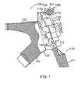
- Fig. 1 shows a head tube assembly and fork for a bicycle with an open steerer configuration according to an embodiment of the present invention.
- Fig. 2 shows a compression adjustment cup which adjusts the location of the upper head tube bearing according to an embodiment of the present invention.
- FIG. 1 shows a front section of a bicycle frame indicated generally by reference 100 with a head tube assembly and fork with an open steerer configuration according to an embodiment of the present invention and indicated generally by reference 120.
- the head tube section and fork assembly are shown in a partial cut-away or sectional view along a line that bisects the head tube assembly and the fork assembly. While embodiments according to the present invention are described in the context of a bicycle, it will be appreciated and understood that the invention may be suitable for other frame geometries or wheeled vehicle configurations with a rotatable head assembly.
- the front section of bicycle frame 100 as depicted in Fig. 1 comprises a top tube 102 and a down tube 104.
- the top tube 102 is connected to the down tube 104 and a head tube 121 in the head tube assembly 120 using known techniques.
- the front section of the bicycle frame 100 includes an external steerer tube indicated generally by reference 106 and an upper steerer section indicated generally by reference 108.
- the bicycle frame 100 also includes a fork assembly indicated generally by reference 110.
- the fork assembly 110 comprises a fork 111 and a fork head or crown 112. According to an embodiment, the fork head 112 is integrated or combined with the external steerer tube 106 wherein the head tube assembly 120 does not include a conventional internal steering tube or axle.
- the external steerer tube 106 can comprise an integrated component with the fork head 112 or a separate component that is connected or otherwise joined to the fork head 112.
- the fork head 112 is adjoined or otherwise affixed to the forks 111 in known manner, which are configured at their respective lower ends to receive the axle of the front wheel.
- the head tube assembly 120 comprises a head tube indicated generally by reference 121, which is affixed or otherwise connected to the respective ends of the top tube 102 and the down tube 104.
- the head tube assembly 120 (i.e. the head tube 121) is configured with a lower bearing 122 and an upper bearing 124.
- the head tube bearings 122, 124 are held in place with respective tabs 123 and 125.
- the head tube bearings 122, 124 can also be held in place using indents, races or other types of guides or holders incorporated into the head tube 120 and/or fork assembly 110.
- the external steerer tube 106 includes a bearing plate or tab indicated generally by reference 107.
- the bearing plate 107 is configured to rotatably couple or engage the external steerer tube 106 to the upper head tube bearing 124, for example, with a matching bearing race or bearing cup, and according to one implementation is further secured by the upper steerer section 108.
- the upper steerer section 108 is connected or clamped to the fork head 112 using a bolt or other type of threaded fastener indicated generally by reference 109 which is screwed into a threaded socket 113 in the fork head 112.
- the upper steerer section 108 is configured to receive a handle bar clamp indicated generally by reference 114.
- the handle bar clamp 114 is clamped or attached to upper steerer section 108 with one or more bolts or threaded fasteners 115a, 115b that are screwed into threaded sockets 117a, 117b in the upper steerer section 108.
- the handle bar clamp 114 securely clamps a handle bar 102.
- the head tube 121 has a curvature on the outside surface indicated generally by reference 123.
- the curvature 123 provides some clearance between the head tube 121 and the fork head or crown 112 when the upper steering section 108 and fork assembly 110 are turned by rotating the handlebars 102.
- the upper steerer section 108 is removable.
- the fork head crown 112 is inserted into the lower end of the head tube 121 and coupled or mated (i.e, with a mating bearing cup, bearing race or other engageable coupler) with the lower bearing 122 in the head tube 121 and then the external steerer tube 106 is coupled to the upper bearing 124, with the bearing plate 107 (and a mating bearing cup or race), and the upper steerer section 108 is attached to secure the assembly.
- Fig. 2 illustrates a method of securing the upper head tube bearing 124 and adjusting the compression on the bearings 122, 124 in order to hold the bearings in place and secure the fork 111 to the frame 100 according to an embodiment of the present invention.
- Fig. 2 shows a split stem 208 including pinch bolts 202 to adjust compression on the split and a threaded hole 203 through the stem above the head tube 121.
- a threaded tube 201 with external threads is provided to mate with the threaded hole 203 through the stem and includes an annular cup or race 204 at the bottom end to mate with the upper head tube bearing 124 in order to hold the bearing in place against a cone 205 moulded to the head tube 121.
- the threaded tube 201 may be rotated within the stem 208 to adjust its height and therefore the distance between the upper and lower bearings 122, 124 and the pressure on them. Once an adjustment is made the pinch bolts 202 may be tightened to prevent further rotation of the threaded tube 201.
- a complete bicycle frame is assembled by connecting the other end of the top tube 102 to a seat tube (not shown).
- the other end of the seat tube is connected or affixed to the other end of the down tube 104 and to a bottom bracket assembly (not shown).
- the bottom bracket assembly is configured to receive a pedal crank assembly (not shown).
- the bicycle frame further comprises a pair of chain stays (not shown) and a pair of seat stays (not shown).
- the tube and frame components for the bicycle frame are affixed or adjoined using known techniques, such as welding or detachable fasteners, etc., to form the complete bicycle frame, as will be familiar to one skilled in the art.
- the bicycle frame is completed with the head tube and fork assembly as described above, front and rear wheels, and a component set (e.g. gears, derailleur's, brakes, etc.).
- the configuration of the head tube assembly 120 provides an internal chamber or cavity inside the head tube assembly 120.
- the internal chamber or cavity inside the head tube assembly 120 is indicated generally by reference 130.
- the steerer tube or axle is eliminated from the head tube assembly 120, and the internal chamber 130 comprises an unobstructed cavity and is unimpeded by any rotating steering mechanism shafts or tubes as found in conventional bicycle designs.
- This configuration substantially eliminates interference between the steering mechanism and internal routing of cables and wires. In this way, cables (e.g. braking cables, gear shifter cables, computer and other sensor cables) are easily routed within the head tube assembly 120 without interference from the steerer tube or axle.
- cables e.g. braking cables, gear shifter cables, computer and other sensor cables
- the upper steerer section 108 includes a hole or aperture indicated generally by reference 132 for routing cables into and out from the internal chamber 130 and the other tubes forming the bicycle frame.
- the upper and lower bearings 124 and 122 have an open bore or void indicated by references 129 and 127, respectively.
- the open bore 129 in the upper bearing 124 allows cables, tubes and/or wires, to be routed from the upper steerer section 108 (i.e. through the hole 132) into the internal chamber 130 and then further down through the down tube 104, for example, to the pedal crank assembly, front and/or rear derailleur's, and/or rear brake components, or to other sections of the frame or bicycle.
- the open bore 127 through the lower bearing 122 allows cable(s), tubes and/or wires, to be routed from/to the upper steerer section 108 and through the fork 111 to components configured with the front wheel, for example, front brake cable(s), computer speed or other sensor cable(s).
- the hole 132 may be located in other sections or portions of the head tube assembly 120 that are adjacent to, or in communication with, the internal chamber 130.
- more than one hole, slot or aperture can be provided for routing cables or wires into and out from the internal chamber 130 and the interior of the tubes forming the bicycle frame.
- a head tube assembly for use with a bicycle frame, said head tube assembly comprising a head tube configured for adjoining to a top tube and to a down tube in the bicycle frame; said head tube including a lower bearing component and an upper bearing component, said lower and upper bearings being configured for rotatably engaging a fork assembly, said fork assembly comprising an external steerer configured to rotate externally to said head tube; an upper steerer section configured to secure said external steerer; and an internal chamber configured with an aperture for receiving one or more cables, and said internal chamber being coupled to said top tube or to said down tube for routing said one or more cables through the interior space of said top tube or said down tube.
- a cycle frame comprising: a bottom bracket; a top tube, a head assembly, a down tube and a seat tube; one end of said top tube and one end of said down tube being affixed to said head tube, and another end of said top tube being affixed to one end of said seat tube; first and second seat stays, and first and second chain stays, and one end of each of said seat stays being affixed to said seat tube, and another end of each of said seat stays being affixed to respective ends of said chain stays; another end of said down tube and another end of said seat tube and another end of each of said chain stays forming a juncture for connecting to said bottom bracket; and said head tube assembly comprising said head tube including a lower bearing component and an upper bearing component, said lower and upper bearings being configured for rotatably engaging a fork assembly, said fork assembly comprising an external steerer configured to rotate externally to said head tube; an upper steerer section configured to secure said external steerer; and said head
Abstract
Description
- This invention relates to wheeled vehicles or cycles, and more particularly to a head tube assembly with an open steerer configuration for a bicycle.
- Bicycle designers continue trying to reduce the aerodynamic drag of bicycles in order to increase riders speed and reduce rider fatigue. In addition to tube shapes, the routing of control cables can be changed to reduce their interaction with air flow against and around the bicycle and thereby reduce the effects of drag.
- Attempts have been made in the art to reduce cable drag by routing one or more cables internally through the bicycle frame. Most known approaches involve providing a hole on the side of steerer tube between the upper and lower bearings and routing the cables through the hole in the steerer tube and into the interior of the bicycle frame and then out respective holes proximate to the components, each brakes, gear derailleur's. Difficulty with the internal routing of cables arises at assemblies or junctions that move or rotate, most notably, the head tube and steerer tube assembly. The known approaches have to deal with the rotation of the internally routed cables as the fork assembly is turned, with the steerer tube rotating relative to the stationary hole on the head tube. The cables routed through the hole can limit the motion of the steerer tube and can also be damaged by the hole as a result of over rotation. The cables will also tend to move inside the steerer tube as the steer tube is rotated, i.e. as the rider turns the bicycle by moving the handlebars. This can cause the derailleur to move.
- Accordingly, there remains a need for improvement in the art.
- The present invention is directed to a head tube assembly with an open steerer configuration for a bicycle.
- According to one embodiment, the present invention comprises a head tube assembly for use with a bicycle frame, the head tube assembly comprising a head tube configured for adjoining to a top tube and to a down tube in the bicycle frame; the head tube including a lower bearing component and an upper bearing component, the lower and upper bearings being configured for rotatably engaging a fork assembly, the fork assembly comprising an external steerer configured to rotate externally to the head tube; an upper steerer section configured to secure the external steerer; and an internal chamber configured with an aperture for receiving one or more cables, and the internal chamber being coupled to the top tube or to the down tube for routing the one or more cables through the interior section of the top tube or the down tube.
- According to another embodiment, the present invention comprises a cycle frame comprising: a bottom bracket; a top tube, a head tube, a down tube and a seat tube; one end of the top tube and one end of the down tube being affixed to the head tube, and another end of the top tube being affixed to one end of the seat tube; first and second seat stays, and first and second chain stays, and one end of each of the seat stays being affixed to the seat tube, and another end of each of the seat stays being affixed to respective ends of the chain stays; another end of the down tube and another end of the seat tube and another end of each of the chain stays forming a juncture for connecting or affixing the bottom bracket; the head tube including a lower bearing component and an upper bearing component, the lower and upper bearing components being configured for rotatably engaging a fork assembly, the fork assembly comprising an external steerer configured to rotate externally to the head tube; an upper steerer section configured to secure the external steerer; and the head tube assembly including an internal chamber configured with an aperture for receiving one or more cables, the said internal chamber being coupled to the top tube or to the down tube for routing said one or more cables through the interior space of the top tube or the down tube.
- Other aspects and features of the present invention will become apparent to those ordinarily skilled in the art upon review of the following exemplary embodiments of the invention in conjunction with the accompanying figures.
- Reference will now be made to the accompanying drawings, which show by way of example, embodiments according to the present invention, and in which:
-
Fig. 1 shows a head tube assembly and fork for a bicycle with an open steerer configuration according to an embodiment of the present invention. -
Fig. 2 shows a compression adjustment cup which adjusts the location of the upper head tube bearing according to an embodiment of the present invention. - Like reference numerals indicate like elements or components in the drawings.
- Reference is first made to
Fig. 1 , which shows a front section of a bicycle frame indicated generally byreference 100 with a head tube assembly and fork with an open steerer configuration according to an embodiment of the present invention and indicated generally byreference 120. InFig. 1 , the head tube section and fork assembly are shown in a partial cut-away or sectional view along a line that bisects the head tube assembly and the fork assembly. While embodiments according to the present invention are described in the context of a bicycle, it will be appreciated and understood that the invention may be suitable for other frame geometries or wheeled vehicle configurations with a rotatable head assembly. - The front section of
bicycle frame 100 as depicted inFig. 1 comprises atop tube 102 and adown tube 104. Thetop tube 102 is connected to thedown tube 104 and ahead tube 121 in thehead tube assembly 120 using known techniques. As shown inFig. 1 , the front section of thebicycle frame 100 includes an external steerer tube indicated generally byreference 106 and an upper steerer section indicated generally byreference 108. Thebicycle frame 100 also includes a fork assembly indicated generally byreference 110. Thefork assembly 110 comprises afork 111 and a fork head orcrown 112. According to an embodiment, thefork head 112 is integrated or combined with theexternal steerer tube 106 wherein thehead tube assembly 120 does not include a conventional internal steering tube or axle. Theexternal steerer tube 106 can comprise an integrated component with thefork head 112 or a separate component that is connected or otherwise joined to thefork head 112. Thefork head 112 is adjoined or otherwise affixed to theforks 111 in known manner, which are configured at their respective lower ends to receive the axle of the front wheel. According to an embodiment, thehead tube assembly 120 comprises a head tube indicated generally byreference 121, which is affixed or otherwise connected to the respective ends of thetop tube 102 and thedown tube 104. - As depicted in
Fig. 1 , the head tube assembly 120 (i.e. the head tube 121) is configured with alower bearing 122 and anupper bearing 124. Thehead tube bearings respective tabs head tube bearings head tube 120 and/orfork assembly 110. According to exemplary implementation, theexternal steerer tube 106 includes a bearing plate or tab indicated generally byreference 107. Thebearing plate 107 is configured to rotatably couple or engage theexternal steerer tube 106 to the upper head tube bearing 124, for example, with a matching bearing race or bearing cup, and according to one implementation is further secured by theupper steerer section 108. - As shown in
Fig. 1 , theupper steerer section 108 is connected or clamped to thefork head 112 using a bolt or other type of threaded fastener indicated generally byreference 109 which is screwed into a threadedsocket 113 in thefork head 112. As also shown inFig. 1 , theupper steerer section 108 is configured to receive a handle bar clamp indicated generally byreference 114. Thehandle bar clamp 114 is clamped or attached toupper steerer section 108 with one or more bolts or threadedfasteners sockets 117a, 117b in theupper steerer section 108. Thehandle bar clamp 114 securely clamps ahandle bar 102. - According to another aspect, the
head tube 121 has a curvature on the outside surface indicated generally byreference 123. Thecurvature 123 provides some clearance between thehead tube 121 and the fork head orcrown 112 when theupper steering section 108 andfork assembly 110 are turned by rotating thehandlebars 102. - As described above, the
upper steerer section 108 is removable. To assemble thehead tube assembly 120 and thefork assembly 110 according to an exemplary implementation, thefork head crown 112 is inserted into the lower end of thehead tube 121 and coupled or mated (i.e, with a mating bearing cup, bearing race or other engageable coupler) with thelower bearing 122 in thehead tube 121 and then theexternal steerer tube 106 is coupled to the upper bearing 124, with the bearing plate 107 (and a mating bearing cup or race), and theupper steerer section 108 is attached to secure the assembly. -
Fig. 2 illustrates a method of securing the upper head tube bearing 124 and adjusting the compression on thebearings fork 111 to theframe 100 according to an embodiment of the present invention.Fig. 2 shows asplit stem 208 includingpinch bolts 202 to adjust compression on the split and a threadedhole 203 through the stem above thehead tube 121. A threadedtube 201 with external threads is provided to mate with the threadedhole 203 through the stem and includes an annular cup orrace 204 at the bottom end to mate with the upper head tube bearing 124 in order to hold the bearing in place against acone 205 moulded to thehead tube 121. The threadedtube 201 may be rotated within thestem 208 to adjust its height and therefore the distance between the upper andlower bearings pinch bolts 202 may be tightened to prevent further rotation of the threadedtube 201. - In known manner, a complete bicycle frame is assembled by connecting the other end of the
top tube 102 to a seat tube (not shown). The other end of the seat tube is connected or affixed to the other end of thedown tube 104 and to a bottom bracket assembly (not shown). The bottom bracket assembly is configured to receive a pedal crank assembly (not shown). The bicycle frame further comprises a pair of chain stays (not shown) and a pair of seat stays (not shown). The tube and frame components for the bicycle frame are affixed or adjoined using known techniques, such as welding or detachable fasteners, etc., to form the complete bicycle frame, as will be familiar to one skilled in the art. The bicycle frame is completed with the head tube and fork assembly as described above, front and rear wheels, and a component set (e.g. gears, derailleur's, brakes, etc.). - Reference is made back to
Fig. 1 . The configuration of thehead tube assembly 120 according to an embodiment of the present invention provides an internal chamber or cavity inside thehead tube assembly 120. The internal chamber or cavity inside thehead tube assembly 120 is indicated generally byreference 130. In accordance with the embodiment, the steerer tube or axle is eliminated from thehead tube assembly 120, and theinternal chamber 130 comprises an unobstructed cavity and is unimpeded by any rotating steering mechanism shafts or tubes as found in conventional bicycle designs. This configuration substantially eliminates interference between the steering mechanism and internal routing of cables and wires. In this way, cables (e.g. braking cables, gear shifter cables, computer and other sensor cables) are easily routed within thehead tube assembly 120 without interference from the steerer tube or axle. As shown inFig. 1 , theupper steerer section 108 includes a hole or aperture indicated generally byreference 132 for routing cables into and out from theinternal chamber 130 and the other tubes forming the bicycle frame. As also shown, the upper andlower bearings references open bore 129 in theupper bearing 124 allows cables, tubes and/or wires, to be routed from the upper steerer section 108 (i.e. through the hole 132) into theinternal chamber 130 and then further down through thedown tube 104, for example, to the pedal crank assembly, front and/or rear derailleur's, and/or rear brake components, or to other sections of the frame or bicycle. Similarly, theopen bore 127 through thelower bearing 122 allows cable(s), tubes and/or wires, to be routed from/to theupper steerer section 108 and through thefork 111 to components configured with the front wheel, for example, front brake cable(s), computer speed or other sensor cable(s). - According to another embodiment, the
hole 132 may be located in other sections or portions of thehead tube assembly 120 that are adjacent to, or in communication with, theinternal chamber 130. According to another aspect, more than one hole, slot or aperture can be provided for routing cables or wires into and out from theinternal chamber 130 and the interior of the tubes forming the bicycle frame. - In summary and according to an embodiment, there is provided a head tube assembly for use with a bicycle frame, said head tube assembly comprising a head tube configured for adjoining to a top tube and to a down tube in the bicycle frame; said head tube including a lower bearing component and an upper bearing component, said lower and upper bearings being configured for rotatably engaging a fork assembly, said fork assembly comprising an external steerer configured to rotate externally to said head tube; an upper steerer section configured to secure said external steerer; and an internal chamber configured with an aperture for receiving one or more cables, and said internal chamber being coupled to said top tube or to said down tube for routing said one or more cables through the interior space of said top tube or said down tube.
- In summary and according to another embodiment, there is provided a cycle frame comprising: a bottom bracket; a top tube, a head assembly, a down tube and a seat tube; one end of said top tube and one end of said down tube being affixed to said head tube, and another end of said top tube being affixed to one end of said seat tube; first and second seat stays, and first and second chain stays, and one end of each of said seat stays being affixed to said seat tube, and another end of each of said seat stays being affixed to respective ends of said chain stays; another end of said down tube and another end of said seat tube and another end of each of said chain stays forming a juncture for connecting to said bottom bracket; and said head tube assembly comprising said head tube including a lower bearing component and an upper bearing component, said lower and upper bearings being configured for rotatably engaging a fork assembly, said fork assembly comprising an external steerer configured to rotate externally to said head tube; an upper steerer section configured to secure said external steerer; and said head tube assembly including an internal chamber configured with an aperture for receiving one or more cables, and said internal chamber being coupled to said top tube or to said down tube for routing said one or more cables through the interior space of said top tube or said down tube.
- The present invention may be embodied in other specific forms without departing from its spirit or essential characteristics. The embodiments described and disclosed are to be considered in all aspects only as illustrative and not restrictive. The scope of the invention is, therefore, indicated by the appended claims rather than by the foregoing description. All changes which come within the meaning and range of equivalency of the claims are to be embraced within their scope.
Claims (12)
- A head tube assembly for use with a bicycle frame, said head tube assembly comprising:a head tube configured for adjoining to a top tube and to a down tube in the bicycle frame;said head tube including a lower bearing component and an upper bearing component, said lower and upper bearings being configured for rotatably engaging a fork assembly, said fork assembly comprising an external steerer configured to rotate externally to said head tube;an upper steerer section configured to secure said external steerer; andan internal chamber configured with an aperture for receiving one or more cables, and said internal chamber being coupled to said top tube or to said down tube for routing said one or more cables through the interior space of said top tube or said down tube.
- The head tube assembly as claimed in claim 1, wherein said internal chamber comprises an internal cavity unobstructed by a steering mechanism.
- The head tube assembly as claimed in claim 1, wherein said lower bearing component is configured to provide a path for routing said one or more cables from said internal chamber through said fork assembly.
- The head tube assembly as claimed in claim 1, wherein said head tube comprises a curved profile, and said curved profile being configured to provide clearance between said head tube and said external steerer.
- The head tube assembly as claimed in claim 1, wherein said aperture is configured in said upper steerer section and said upper bearing component includes a bore for routing said one or more cables from said aperture and through said upper bearing component into said internal chamber.
- The head tube assembly as claimed in claim 5, wherein said one or more cables comprise one of a gear shifter cable, a brake cable and a sensor cable.
- A cycle frame comprising:a bottom bracket;a top tube, a head tube assembly comprising a head tube, a down tube and a seat tube;one end of said top tube and one end of said down tube being affixed to said head tube, and another end of said top tube being affixed to one end of said seat tube;first and second seat stays, and first and second chain stays, and one end of each of said seat stays being affixed to said seat tube, and another end of each of said seat stays being affixed to respective ends of said chain stays;another end of said down tube and another end of said seat tube and another end of each of said chain stays forming a juncture for connecting to said bottom bracket; andsaid head tube including a lower bearing component and an upper bearing component, said lower and upper bearings being configured for rotatably engaging a fork assembly, said fork assembly comprising an external steerer configured to rotate externally to said head tube;an upper steerer section configured to secure said external steerer; andsaid head tube assembly including an internal chamber configured with an aperture for receiving one or more cables, and said internal chamber being coupled to said top tube or to said down tube for routing said one or more cables through the interior space of said top tube or said down tube.
- The cycle frame as claimed in claim 7, wherein said internal chamber comprises an internal cavity unobstructed by a steering mechanism.
- The cycle frame as claimed in claim 7, wherein said lower bearing component is configured to provide a path for routing said one or more cables from said internal chamber through said fork assembly.
- The cycle frame as claimed in claim 7, wherein said head tube comprises a curved exterior profile, and said curved exterior profile being configured to provide clearance between said head tube and said external steerer.
- The cycle frame assembly as claimed in claim 7, wherein said aperture is configured in said upper steerer section and said upper bearing component includes a bore for routing said one or more cables from said aperture and through said upper bearing component into said internal chamber through said top tube or said down tube to other sections of the cycle frame.
- The head tube assembly as claimed in claim 1, wherein said upper bearing is held in place by a race or cup located at a lower end of a threaded tube, said threaded tube including external threads extending upwardly from said upper bearing into a threaded hole in a stem, said threaded hole including internal threads that mate with the external threads of the threaded tube such that the distance between the upper and lower bearings can be adjusted by rotating the threaded tube in the stem.
Applications Claiming Priority (1)
| Application Number | Priority Date | Filing Date | Title |
|---|---|---|---|
| US201161504428P | 2011-07-05 | 2011-07-05 |
Publications (2)
| Publication Number | Publication Date |
|---|---|
| EP2543579A1 true EP2543579A1 (en) | 2013-01-09 |
| EP2543579B1 EP2543579B1 (en) | 2016-04-27 |
Family
ID=46466249
Family Applications (1)
| Application Number | Title | Priority Date | Filing Date |
|---|---|---|---|
| EP12175216.6A Not-in-force EP2543579B1 (en) | 2011-07-05 | 2012-07-05 | Head tube assembly for a bicycle with cable access routing in an open steerer configuration |
Country Status (3)
| Country | Link |
|---|---|
| US (1) | US20130175782A1 (en) |
| EP (1) | EP2543579B1 (en) |
| CA (1) | CA2782234A1 (en) |
Cited By (2)
| Publication number | Priority date | Publication date | Assignee | Title |
|---|---|---|---|---|
| EP2718173A1 (en) * | 2011-06-09 | 2014-04-16 | Wilier Triestina S.p.A. | Bicycle fork |
| US10906605B2 (en) | 2018-07-31 | 2021-02-02 | Trek Bicycle Corporation | Dual crown steering assembly |
Families Citing this family (2)
| Publication number | Priority date | Publication date | Assignee | Title |
|---|---|---|---|---|
| DE102012111204A1 (en) * | 2012-04-20 | 2013-10-24 | Wolfgang Göring | Rotor system for a bicycle |
| FR3020032B1 (en) * | 2014-04-18 | 2016-04-01 | Look Cycle Int | DEVICE FOR GUIDING A FLEXIBLE BONDING MEMBER THROUGH A CYCLE FRAME |
Citations (5)
| Publication number | Priority date | Publication date | Assignee | Title |
|---|---|---|---|---|
| EP1529724A1 (en) * | 2003-11-07 | 2005-05-11 | Shimano Inc. | Bicycle headset structure |
| EP1529725A1 (en) * | 2003-11-04 | 2005-05-11 | Shimano Inc. | Expandable bicycle headset structure |
| FR2864938A1 (en) * | 2004-01-09 | 2005-07-15 | Jerome Cauwet | Front steering system for cycle e.g. motorcycle, has fork fixed at lower end of plunger, where radial position of fork is varied to adjust distance between fork axle and steering axle |
| EP1787899A1 (en) * | 2005-11-16 | 2007-05-23 | Shimano Inc. | Bicycle cable installation aiding device |
| WO2009146552A1 (en) * | 2008-06-06 | 2009-12-10 | Société De Velo En Libre-Service | Fork assembly for a bicycle |
Family Cites Families (1)
| Publication number | Priority date | Publication date | Assignee | Title |
|---|---|---|---|---|
| US7210694B2 (en) * | 2004-09-17 | 2007-05-01 | Rodney J Trenne | Integrated front fork hinge and brake system for bicycles |
-
2012
- 2012-07-05 CA CA2782234A patent/CA2782234A1/en not_active Abandoned
- 2012-07-05 US US13/541,983 patent/US20130175782A1/en not_active Abandoned
- 2012-07-05 EP EP12175216.6A patent/EP2543579B1/en not_active Not-in-force
Patent Citations (5)
| Publication number | Priority date | Publication date | Assignee | Title |
|---|---|---|---|---|
| EP1529725A1 (en) * | 2003-11-04 | 2005-05-11 | Shimano Inc. | Expandable bicycle headset structure |
| EP1529724A1 (en) * | 2003-11-07 | 2005-05-11 | Shimano Inc. | Bicycle headset structure |
| FR2864938A1 (en) * | 2004-01-09 | 2005-07-15 | Jerome Cauwet | Front steering system for cycle e.g. motorcycle, has fork fixed at lower end of plunger, where radial position of fork is varied to adjust distance between fork axle and steering axle |
| EP1787899A1 (en) * | 2005-11-16 | 2007-05-23 | Shimano Inc. | Bicycle cable installation aiding device |
| WO2009146552A1 (en) * | 2008-06-06 | 2009-12-10 | Société De Velo En Libre-Service | Fork assembly for a bicycle |
Cited By (3)
| Publication number | Priority date | Publication date | Assignee | Title |
|---|---|---|---|---|
| EP2718173A1 (en) * | 2011-06-09 | 2014-04-16 | Wilier Triestina S.p.A. | Bicycle fork |
| EP2718173B1 (en) * | 2011-06-09 | 2016-09-21 | Wilier Triestina S.p.A. | Bicycle fork |
| US10906605B2 (en) | 2018-07-31 | 2021-02-02 | Trek Bicycle Corporation | Dual crown steering assembly |
Also Published As
| Publication number | Publication date |
|---|---|
| US20130175782A1 (en) | 2013-07-11 |
| EP2543579B1 (en) | 2016-04-27 |
| CA2782234A1 (en) | 2013-01-05 |
Similar Documents
| Publication | Publication Date | Title |
|---|---|---|
| US9096287B2 (en) | Apparatus and method for routing bicycle control cables | |
| US8684386B2 (en) | Head tube assembly for a bicycle with cable access routing in an open steerer configuration | |
| US7669871B2 (en) | Bicycle wheel securing adapter and bicycle fork using the same | |
| US7527277B2 (en) | Bicycle crank | |
| US7891688B2 (en) | Bicycle frame with articulating linkage mounting arrangement | |
| US7650817B2 (en) | Bicycle crank assembly | |
| US20120167709A1 (en) | Length adjustable bicycle crank | |
| US9855794B1 (en) | Bicycle hub assembly | |
| US7562941B2 (en) | Bicycle disc brake hub | |
| US20060112780A1 (en) | Bicycle crank axle bearing assembly | |
| US20140137698A1 (en) | Bicycle handlebar assembly | |
| US9156524B2 (en) | Derailleur | |
| US10053187B2 (en) | Bicycle rear sprocket assembly and bicycle rear sprocket | |
| US20180134340A1 (en) | Bicycle front sprocket, bicycle crank assembly, and bicycle drive train | |
| EP1659056B1 (en) | Bicycle crank axle assembly | |
| EP2543579B1 (en) | Head tube assembly for a bicycle with cable access routing in an open steerer configuration | |
| US8231135B2 (en) | Device for adjusting the trail of a cycle front wheel assembly, a wheel equipped with such device, and a method of using same | |
| JP5931138B2 (en) | Steering stem assembly for motorcycles | |
| US9388847B1 (en) | Bottom bracket for bicycles | |
| US20080302588A1 (en) | Motorcycle steering using compound leverage | |
| US9821880B2 (en) | Bicycle rim brake | |
| US20230002003A1 (en) | Adjustable axle retaining structure | |
| TWI526359B (en) | Bicycle brake arm | |
| US20110193314A1 (en) | Asymmetrical or off-center bottom bracket |
Legal Events
| Date | Code | Title | Description |
|---|---|---|---|
| PUAI | Public reference made under article 153(3) epc to a published international application that has entered the european phase |
Free format text: ORIGINAL CODE: 0009012 |
|
| AK | Designated contracting states |
Kind code of ref document: A1 Designated state(s): AL AT BE BG CH CY CZ DE DK EE ES FI FR GB GR HR HU IE IS IT LI LT LU LV MC MK MT NL NO PL PT RO RS SE SI SK SM TR |
|
| AX | Request for extension of the european patent |
Extension state: BA ME |
|
| 17P | Request for examination filed |
Effective date: 20130628 |
|
| RBV | Designated contracting states (corrected) |
Designated state(s): AL AT BE BG CH CY CZ DE DK EE ES FI FR GB GR HR HU IE IS IT LI LT LU LV MC MK MT NL NO PL PT RO RS SE SI SK SM TR |
|
| GRAP | Despatch of communication of intention to grant a patent |
Free format text: ORIGINAL CODE: EPIDOSNIGR1 |
|
| INTG | Intention to grant announced |
Effective date: 20151105 |
|
| GRAS | Grant fee paid |
Free format text: ORIGINAL CODE: EPIDOSNIGR3 |
|
| GRAA | (expected) grant |
Free format text: ORIGINAL CODE: 0009210 |
|
| AK | Designated contracting states |
Kind code of ref document: B1 Designated state(s): AL AT BE BG CH CY CZ DE DK EE ES FI FR GB GR HR HU IE IS IT LI LT LU LV MC MK MT NL NO PL PT RO RS SE SI SK SM TR |
|
| REG | Reference to a national code |
Ref country code: GB Ref legal event code: FG4D |
|
| REG | Reference to a national code |
Ref country code: CH Ref legal event code: EP |
|
| REG | Reference to a national code |
Ref country code: AT Ref legal event code: REF Ref document number: 794437 Country of ref document: AT Kind code of ref document: T Effective date: 20160515 |
|
| REG | Reference to a national code |
Ref country code: IE Ref legal event code: FG4D |
|
| REG | Reference to a national code |
Ref country code: DE Ref legal event code: R096 Ref document number: 602012017558 Country of ref document: DE |
|
| REG | Reference to a national code |
Ref country code: FR Ref legal event code: PLFP Year of fee payment: 5 |
|
| REG | Reference to a national code |
Ref country code: NL Ref legal event code: FP |
|
| REG | Reference to a national code |
Ref country code: LT Ref legal event code: MG4D |
|
| REG | Reference to a national code |
Ref country code: AT Ref legal event code: MK05 Ref document number: 794437 Country of ref document: AT Kind code of ref document: T Effective date: 20160427 |
|
| PG25 | Lapsed in a contracting state [announced via postgrant information from national office to epo] |
Ref country code: FI Free format text: LAPSE BECAUSE OF FAILURE TO SUBMIT A TRANSLATION OF THE DESCRIPTION OR TO PAY THE FEE WITHIN THE PRESCRIBED TIME-LIMIT Effective date: 20160427 Ref country code: NO Free format text: LAPSE BECAUSE OF FAILURE TO SUBMIT A TRANSLATION OF THE DESCRIPTION OR TO PAY THE FEE WITHIN THE PRESCRIBED TIME-LIMIT Effective date: 20160727 Ref country code: PL Free format text: LAPSE BECAUSE OF FAILURE TO SUBMIT A TRANSLATION OF THE DESCRIPTION OR TO PAY THE FEE WITHIN THE PRESCRIBED TIME-LIMIT Effective date: 20160427 Ref country code: LT Free format text: LAPSE BECAUSE OF FAILURE TO SUBMIT A TRANSLATION OF THE DESCRIPTION OR TO PAY THE FEE WITHIN THE PRESCRIBED TIME-LIMIT Effective date: 20160427 |
|
| PG25 | Lapsed in a contracting state [announced via postgrant information from national office to epo] |
Ref country code: HR Free format text: LAPSE BECAUSE OF FAILURE TO SUBMIT A TRANSLATION OF THE DESCRIPTION OR TO PAY THE FEE WITHIN THE PRESCRIBED TIME-LIMIT Effective date: 20160427 Ref country code: ES Free format text: LAPSE BECAUSE OF FAILURE TO SUBMIT A TRANSLATION OF THE DESCRIPTION OR TO PAY THE FEE WITHIN THE PRESCRIBED TIME-LIMIT Effective date: 20160427 Ref country code: PT Free format text: LAPSE BECAUSE OF FAILURE TO SUBMIT A TRANSLATION OF THE DESCRIPTION OR TO PAY THE FEE WITHIN THE PRESCRIBED TIME-LIMIT Effective date: 20160829 Ref country code: GR Free format text: LAPSE BECAUSE OF FAILURE TO SUBMIT A TRANSLATION OF THE DESCRIPTION OR TO PAY THE FEE WITHIN THE PRESCRIBED TIME-LIMIT Effective date: 20160728 Ref country code: AT Free format text: LAPSE BECAUSE OF FAILURE TO SUBMIT A TRANSLATION OF THE DESCRIPTION OR TO PAY THE FEE WITHIN THE PRESCRIBED TIME-LIMIT Effective date: 20160427 Ref country code: LV Free format text: LAPSE BECAUSE OF FAILURE TO SUBMIT A TRANSLATION OF THE DESCRIPTION OR TO PAY THE FEE WITHIN THE PRESCRIBED TIME-LIMIT Effective date: 20160427 Ref country code: SE Free format text: LAPSE BECAUSE OF FAILURE TO SUBMIT A TRANSLATION OF THE DESCRIPTION OR TO PAY THE FEE WITHIN THE PRESCRIBED TIME-LIMIT Effective date: 20160427 Ref country code: RS Free format text: LAPSE BECAUSE OF FAILURE TO SUBMIT A TRANSLATION OF THE DESCRIPTION OR TO PAY THE FEE WITHIN THE PRESCRIBED TIME-LIMIT Effective date: 20160427 |
|
| PG25 | Lapsed in a contracting state [announced via postgrant information from national office to epo] |
Ref country code: BE Free format text: LAPSE BECAUSE OF FAILURE TO SUBMIT A TRANSLATION OF THE DESCRIPTION OR TO PAY THE FEE WITHIN THE PRESCRIBED TIME-LIMIT Effective date: 20160427 |
|
| REG | Reference to a national code |
Ref country code: DE Ref legal event code: R097 Ref document number: 602012017558 Country of ref document: DE |
|
| PG25 | Lapsed in a contracting state [announced via postgrant information from national office to epo] |
Ref country code: RO Free format text: LAPSE BECAUSE OF FAILURE TO SUBMIT A TRANSLATION OF THE DESCRIPTION OR TO PAY THE FEE WITHIN THE PRESCRIBED TIME-LIMIT Effective date: 20160427 Ref country code: SK Free format text: LAPSE BECAUSE OF FAILURE TO SUBMIT A TRANSLATION OF THE DESCRIPTION OR TO PAY THE FEE WITHIN THE PRESCRIBED TIME-LIMIT Effective date: 20160427 Ref country code: EE Free format text: LAPSE BECAUSE OF FAILURE TO SUBMIT A TRANSLATION OF THE DESCRIPTION OR TO PAY THE FEE WITHIN THE PRESCRIBED TIME-LIMIT Effective date: 20160427 Ref country code: CZ Free format text: LAPSE BECAUSE OF FAILURE TO SUBMIT A TRANSLATION OF THE DESCRIPTION OR TO PAY THE FEE WITHIN THE PRESCRIBED TIME-LIMIT Effective date: 20160427 Ref country code: DK Free format text: LAPSE BECAUSE OF FAILURE TO SUBMIT A TRANSLATION OF THE DESCRIPTION OR TO PAY THE FEE WITHIN THE PRESCRIBED TIME-LIMIT Effective date: 20160427 |
|
| PG25 | Lapsed in a contracting state [announced via postgrant information from national office to epo] |
Ref country code: SM Free format text: LAPSE BECAUSE OF FAILURE TO SUBMIT A TRANSLATION OF THE DESCRIPTION OR TO PAY THE FEE WITHIN THE PRESCRIBED TIME-LIMIT Effective date: 20160427 |
|
| REG | Reference to a national code |
Ref country code: CH Ref legal event code: PL |
|
| PLBE | No opposition filed within time limit |
Free format text: ORIGINAL CODE: 0009261 |
|
| STAA | Information on the status of an ep patent application or granted ep patent |
Free format text: STATUS: NO OPPOSITION FILED WITHIN TIME LIMIT |
|
| PG25 | Lapsed in a contracting state [announced via postgrant information from national office to epo] |
Ref country code: MC Free format text: LAPSE BECAUSE OF FAILURE TO SUBMIT A TRANSLATION OF THE DESCRIPTION OR TO PAY THE FEE WITHIN THE PRESCRIBED TIME-LIMIT Effective date: 20160427 |
|
| 26N | No opposition filed |
Effective date: 20170130 |
|
| PG25 | Lapsed in a contracting state [announced via postgrant information from national office to epo] |
Ref country code: CH Free format text: LAPSE BECAUSE OF NON-PAYMENT OF DUE FEES Effective date: 20160731 Ref country code: LI Free format text: LAPSE BECAUSE OF NON-PAYMENT OF DUE FEES Effective date: 20160731 |
|
| REG | Reference to a national code |
Ref country code: IE Ref legal event code: MM4A |
|
| PG25 | Lapsed in a contracting state [announced via postgrant information from national office to epo] |
Ref country code: SI Free format text: LAPSE BECAUSE OF FAILURE TO SUBMIT A TRANSLATION OF THE DESCRIPTION OR TO PAY THE FEE WITHIN THE PRESCRIBED TIME-LIMIT Effective date: 20160427 |
|
| REG | Reference to a national code |
Ref country code: FR Ref legal event code: PLFP Year of fee payment: 6 |
|
| PG25 | Lapsed in a contracting state [announced via postgrant information from national office to epo] |
Ref country code: IE Free format text: LAPSE BECAUSE OF NON-PAYMENT OF DUE FEES Effective date: 20160705 |
|
| PG25 | Lapsed in a contracting state [announced via postgrant information from national office to epo] |
Ref country code: LU Free format text: LAPSE BECAUSE OF NON-PAYMENT OF DUE FEES Effective date: 20160705 |
|
| PGFP | Annual fee paid to national office [announced via postgrant information from national office to epo] |
Ref country code: NL Payment date: 20170714 Year of fee payment: 6 |
|
| PGFP | Annual fee paid to national office [announced via postgrant information from national office to epo] |
Ref country code: FR Payment date: 20170718 Year of fee payment: 6 |
|
| PG25 | Lapsed in a contracting state [announced via postgrant information from national office to epo] |
Ref country code: CY Free format text: LAPSE BECAUSE OF FAILURE TO SUBMIT A TRANSLATION OF THE DESCRIPTION OR TO PAY THE FEE WITHIN THE PRESCRIBED TIME-LIMIT Effective date: 20160427 Ref country code: HU Free format text: LAPSE BECAUSE OF FAILURE TO SUBMIT A TRANSLATION OF THE DESCRIPTION OR TO PAY THE FEE WITHIN THE PRESCRIBED TIME-LIMIT; INVALID AB INITIO Effective date: 20120705 |
|
| PG25 | Lapsed in a contracting state [announced via postgrant information from national office to epo] |
Ref country code: MT Free format text: LAPSE BECAUSE OF NON-PAYMENT OF DUE FEES Effective date: 20160731 Ref country code: TR Free format text: LAPSE BECAUSE OF FAILURE TO SUBMIT A TRANSLATION OF THE DESCRIPTION OR TO PAY THE FEE WITHIN THE PRESCRIBED TIME-LIMIT Effective date: 20160427 Ref country code: MK Free format text: LAPSE BECAUSE OF FAILURE TO SUBMIT A TRANSLATION OF THE DESCRIPTION OR TO PAY THE FEE WITHIN THE PRESCRIBED TIME-LIMIT Effective date: 20160427 Ref country code: IS Free format text: LAPSE BECAUSE OF FAILURE TO SUBMIT A TRANSLATION OF THE DESCRIPTION OR TO PAY THE FEE WITHIN THE PRESCRIBED TIME-LIMIT Effective date: 20160427 |
|
| PG25 | Lapsed in a contracting state [announced via postgrant information from national office to epo] |
Ref country code: BG Free format text: LAPSE BECAUSE OF FAILURE TO SUBMIT A TRANSLATION OF THE DESCRIPTION OR TO PAY THE FEE WITHIN THE PRESCRIBED TIME-LIMIT Effective date: 20160427 |
|
| PG25 | Lapsed in a contracting state [announced via postgrant information from national office to epo] |
Ref country code: AL Free format text: LAPSE BECAUSE OF FAILURE TO SUBMIT A TRANSLATION OF THE DESCRIPTION OR TO PAY THE FEE WITHIN THE PRESCRIBED TIME-LIMIT Effective date: 20160427 |
|
| PGFP | Annual fee paid to national office [announced via postgrant information from national office to epo] |
Ref country code: IT Payment date: 20180718 Year of fee payment: 7 Ref country code: DE Payment date: 20180709 Year of fee payment: 7 |
|
| PGFP | Annual fee paid to national office [announced via postgrant information from national office to epo] |
Ref country code: GB Payment date: 20180705 Year of fee payment: 7 |
|
| REG | Reference to a national code |
Ref country code: NL Ref legal event code: MM Effective date: 20180801 |
|
| PG25 | Lapsed in a contracting state [announced via postgrant information from national office to epo] |
Ref country code: FR Free format text: LAPSE BECAUSE OF NON-PAYMENT OF DUE FEES Effective date: 20180731 |
|
| PG25 | Lapsed in a contracting state [announced via postgrant information from national office to epo] |
Ref country code: NL Free format text: LAPSE BECAUSE OF NON-PAYMENT OF DUE FEES Effective date: 20180801 |
|
| REG | Reference to a national code |
Ref country code: DE Ref legal event code: R079 Ref document number: 602012017558 Country of ref document: DE Free format text: PREVIOUS MAIN CLASS: B62J0006180000 Ipc: B62J0011190000 |
|
| REG | Reference to a national code |
Ref country code: DE Ref legal event code: R119 Ref document number: 602012017558 Country of ref document: DE |
|
| GBPC | Gb: european patent ceased through non-payment of renewal fee |
Effective date: 20190705 |
|
| PG25 | Lapsed in a contracting state [announced via postgrant information from national office to epo] |
Ref country code: GB Free format text: LAPSE BECAUSE OF NON-PAYMENT OF DUE FEES Effective date: 20190705 Ref country code: DE Free format text: LAPSE BECAUSE OF NON-PAYMENT OF DUE FEES Effective date: 20200201 |
|
| PG25 | Lapsed in a contracting state [announced via postgrant information from national office to epo] |
Ref country code: IT Free format text: LAPSE BECAUSE OF NON-PAYMENT OF DUE FEES Effective date: 20190705 |