EP3266683B1 - Chassis for self-propelled operating machines - Google Patents
Chassis for self-propelled operating machines Download PDFInfo
- Publication number
- EP3266683B1 EP3266683B1 EP17001128.2A EP17001128A EP3266683B1 EP 3266683 B1 EP3266683 B1 EP 3266683B1 EP 17001128 A EP17001128 A EP 17001128A EP 3266683 B1 EP3266683 B1 EP 3266683B1
- Authority
- EP
- European Patent Office
- Prior art keywords
- ballast member
- chassis
- frame
- rear part
- ballast
- Prior art date
- Legal status (The legal status is an assumption and is not a legal conclusion. Google has not performed a legal analysis and makes no representation as to the accuracy of the status listed.)
- Active
Links
Images

Classifications
-
- B—PERFORMING OPERATIONS; TRANSPORTING
- B62—LAND VEHICLES FOR TRAVELLING OTHERWISE THAN ON RAILS
- B62D—MOTOR VEHICLES; TRAILERS
- B62D21/00—Understructures, i.e. chassis frame on which a vehicle body may be mounted
- B62D21/11—Understructures, i.e. chassis frame on which a vehicle body may be mounted with resilient means for suspension, e.g. of wheels or engine; sub-frames for mounting engine or suspensions
-
- B—PERFORMING OPERATIONS; TRANSPORTING
- B62—LAND VEHICLES FOR TRAVELLING OTHERWISE THAN ON RAILS
- B62D—MOTOR VEHICLES; TRAILERS
- B62D21/00—Understructures, i.e. chassis frame on which a vehicle body may be mounted
- B62D21/18—Understructures, i.e. chassis frame on which a vehicle body may be mounted characterised by the vehicle type and not provided for in groups B62D21/02 - B62D21/17
- B62D21/186—Understructures, i.e. chassis frame on which a vehicle body may be mounted characterised by the vehicle type and not provided for in groups B62D21/02 - B62D21/17 for building site vehicles or multi-purpose tractors
-
- B—PERFORMING OPERATIONS; TRANSPORTING
- B62—LAND VEHICLES FOR TRAVELLING OTHERWISE THAN ON RAILS
- B62D—MOTOR VEHICLES; TRAILERS
- B62D49/00—Tractors
- B62D49/06—Tractors adapted for multi-purpose use
- B62D49/0621—Tractors adapted for multi-purpose use comprising traction increasing arrangements, e.g. all-wheel traction devices, multiple-axle traction arrangements, auxiliary traction increasing devices
Definitions
- the present invention relates to a chassis for self-propelled operating machines.
- the loadbearing structure of self-propelled operating machines like that of other vehicles, is constituted by a chassis that determines its shape and defines the position of the parts required by the machines.
- a chassis is formed by strong metallic profiled members which are mutually connected so as to constitute a single resisting assembly, to which the engine, the body, the axle shafts and any work equipment are fixed.
- WO81/03154 discloses an aircraft tug having an equipment support frame in the form of a heavy base plate carried beneath an operator's station portion of a conventional tractor chassis, and a pair of transversely spaced struts secured to the front portion of the base plate and arranged to extend forwardly thereof.
- the front ends of the struts have attachment means for the support of equipment, such as a towing hitch, at the front of the tractor.
- First and second attachment means are provided for respectively securing the base plate and struts to the chassis.
- GB2120987 discloses a farm tractor having an engine placed above the front axle and a gearbox fitted in the rear part of the tractor; a fuel tank is fitted between the engine and the gearbox over a substantial proportion of the length of the tractor.
- the fuel tank comprises a box-girder shaped carrying component of the tractor frame.
- US2013/292386 discloses a system including a diesel exhaust fluid tank and a fuel tank arranged in a portion of a vehicle to give that portion multiple structural functions.
- the system may be arranged to form a part of a counterweight on a work vehicle.
- chassis may actually assume very different shapes than the one described above: for example, many operating machines are provided with a frame that is constituted by a front part and a rear part, which are mutually articulated by articulation systems.
- the chassis In the case of operating machines designed to support work equipment, the chassis is considerably strengthened and in some cases is also ballasted.
- ballast members When the machines are assigned to lifting loads or are equipped with particularly heavy work tools, removable ballast members, usually constituted by cement blocks, are in fact usually attached to the chassis.
- the aim of the ballast members is obviously to rebalance the weights involved in order to avoid the possible tipping of the machine.
- the aim of the invention is to solve the problems described above, providing a chassis, particularly for self-propelled operating machines, that allows to lower the center of gravity of the operating machine that uses it, so as to increase the stability of the machine even during load lifting.
- a particular object of the invention is to provide a chassis in which the arrangement of the counterweights is not entrusted exclusively to the expertize of the operator.
- Another object of the invention is to provide a chassis that is capable of minimizing the vibrations produced by the engine.
- a further object of the invention is to provide a chassis composed of a reduced number of parts, with consequent savings both in economic terms and in terms of assembly time.
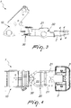
- the chassis particularly for self-propelled operating machines, according to the invention, globally designated by the reference numeral 1, includes a frame which is adapted to support a motorized movement means and a means for the control of an operating machine, which may be of a per se known type and are not shown in the figures.
- the movement means may be constituted by wheels or tracks which are associated with the frame and are actuated by hydraulic motors controlled by a hydraulic pump.
- the hydraulic pump may be actuated by a motor means, such as an internal combustion engine or by an electric motor.
- the movement means interacts with a steering system which, together with the controls for the actuation of the hydraulic motors, constitutes the means for the control of the operating machine.
- the frame has a front part 10, which is designed to support one or more work tools, and a rear part 20; the front part 10 and the rear part 20 are mutually articulated by an articulation means 30.
- the rear part 20 has a pair of longitudinal members 21 which are mutually rigidly connected by means of a reinforcement deck 22 which is arranged transversely.
- the chassis 1 includes a ballast member 2, which becomes an integral part of the frame and is adapted to support mechanical parts of the operating machine.
- the ballast member 2 is composed of a single part which is joined to the rear part 20 of the frame by an adapted fastening means.
- the ballast member 2 is joined directly to the frame and is arranged to the rear at a height from the ground that substantially matches the height of the axle shafts of the operating machine, allowing to lower the center of gravity of the operating machine as close as possible to the ground.
- the ballast member 2 is preferably made of metal and is substantially C-shaped, so that the ends of the C can be joined to the ends of the longitudinal members 21 that are opposite to the ones joined to the articulation means 30.
- a substantially concave seat 3 is provided on the ballast member 2 and is designed to accommodate the motor means.
- the engine or a part thereof is accommodated in the seat 3 and is connected to the ballast member 2 with the interposition of silent blocks, i.e., rubber pads which support the engine and absorb vibrations.
- silent blocks i.e., rubber pads which support the engine and absorb vibrations.
- the inertia of the ballast member 2 allows to effectively contrast the vibration generated by the engine.
- the ballast member 2 is also provided with coupling portions and members which are constituted, in this embodiment, by threaded holes 4 which allow to integrate auxiliary components in the chassis 1, such as for example tow hooks, additional counterweights, or other components already used in chassis with known technology.
- the chassis according to the invention by virtue of the presence of a ballast member which becomes an active and constructive part of the frame, as well as the particular arrangement of the member, is capable of lowering the center of gravity of the operating machine that uses it, thus increasing the stability of the machine even during load lifting.
- the inertia of the ballast member allows to effectively contrast the vibrations generated by the engine.
Landscapes
- Engineering & Computer Science (AREA)
- Chemical & Material Sciences (AREA)
- Combustion & Propulsion (AREA)
- Transportation (AREA)
- Mechanical Engineering (AREA)
- Architecture (AREA)
- Structural Engineering (AREA)
- Body Structure For Vehicles (AREA)
- Platform Screen Doors And Railroad Systems (AREA)
Description
- The present invention relates to a chassis for self-propelled operating machines.
- As is known, the loadbearing structure of self-propelled operating machines, like that of other vehicles, is constituted by a chassis that determines its shape and defines the position of the parts required by the machines.
- In general, a chassis is formed by strong metallic profiled members which are mutually connected so as to constitute a single resisting assembly, to which the engine, the body, the axle shafts and any work equipment are fixed.
-
WO81/03154 -
GB2120987 -
US2013/292386 discloses a system including a diesel exhaust fluid tank and a fuel tank arranged in a portion of a vehicle to give that portion multiple structural functions. The system may be arranged to form a part of a counterweight on a work vehicle. - With particular reference to operating machines, it can be noted that the chassis may actually assume very different shapes than the one described above: for example, many operating machines are provided with a frame that is constituted by a front part and a rear part, which are mutually articulated by articulation systems.
- In the case of operating machines designed to support work equipment, the chassis is considerably strengthened and in some cases is also ballasted.
- When the machines are assigned to lifting loads or are equipped with particularly heavy work tools, removable ballast members, usually constituted by cement blocks, are in fact usually attached to the chassis.
- The aim of the ballast members is obviously to rebalance the weights involved in order to avoid the possible tipping of the machine.
- In this last regard, however, it is important to note that the choice to attach counterweights to the chassis or not, and how many to optionally attach, is often entrusted to the experience and professionalism of the operator, with the less than remote possibility that the choices made might be less than optimum.
- In addition to this, one should consider that in general the coupling points for the ballast members are provided at positions that are significantly higher than the axle shafts and this causes a rise in the center of gravity of the machine.
- The aim of the invention is to solve the problems described above, providing a chassis, particularly for self-propelled operating machines, that allows to lower the center of gravity of the operating machine that uses it, so as to increase the stability of the machine even during load lifting.
- Within the scope of this aim, a particular object of the invention is to provide a chassis in which the arrangement of the counterweights is not entrusted exclusively to the expertize of the operator.
- Another object of the invention is to provide a chassis that is capable of minimizing the vibrations produced by the engine.
- A further object of the invention is to provide a chassis composed of a reduced number of parts, with consequent savings both in economic terms and in terms of assembly time.
- This aim, as well as these and other objects which will become better apparent hereinafter, are achieved by a chassis, for self-propelled operating machines, as claimed in the appended claims.
- Further characteristics and advantages will become better apparent from the description of a preferred but not exclusive embodiment of a chassis according to the invention, illustrated by way of nonlimiting example in the accompanying drawings, wherein:
-
Figure 1 is a perspective view of a chassis according to the inventionFigure 2 is another perspective view of the chassis according to the invention; -
Figure 3 is a side view of the chassis according to the invention; -
Figure 4 is a top view of the chassis according to the invention. - With reference to the cited figures, the chassis, particularly for self-propelled operating machines, according to the invention, globally designated by the
reference numeral 1, includes a frame which is adapted to support a motorized movement means and a means for the control of an operating machine, which may be of a per se known type and are not shown in the figures. - For example, the movement means may be constituted by wheels or tracks which are associated with the frame and are actuated by hydraulic motors controlled by a hydraulic pump.
- The hydraulic pump may be actuated by a motor means, such as an internal combustion engine or by an electric motor.
- The movement means interacts with a steering system which, together with the controls for the actuation of the hydraulic motors, constitutes the means for the control of the operating machine.
- It is evident to the person skilled in the art that the movement means and the control means of the operating machine may also have configurations that are different from the ones described above.
- According to the present invention, the frame has a
front part 10, which is designed to support one or more work tools, and arear part 20; thefront part 10 and therear part 20 are mutually articulated by an articulation means 30. - The
rear part 20 has a pair oflongitudinal members 21 which are mutually rigidly connected by means of areinforcement deck 22 which is arranged transversely. - According to the present invention, the
chassis 1 includes aballast member 2, which becomes an integral part of the frame and is adapted to support mechanical parts of the operating machine. - The
ballast member 2 is composed of a single part which is joined to therear part 20 of the frame by an adapted fastening means. - The
ballast member 2 is joined directly to the frame and is arranged to the rear at a height from the ground that substantially matches the height of the axle shafts of the operating machine, allowing to lower the center of gravity of the operating machine as close as possible to the ground. - This evidently provides considerable benefits, especially if the machine is assigned to lifting loads or equipped with particularly heavy tools.
- The
ballast member 2 is preferably made of metal and is substantially C-shaped, so that the ends of the C can be joined to the ends of thelongitudinal members 21 that are opposite to the ones joined to the articulation means 30. - A substantially
concave seat 3 is provided on theballast member 2 and is designed to accommodate the motor means. - In practice, the engine or a part thereof is accommodated in the
seat 3 and is connected to theballast member 2 with the interposition of silent blocks, i.e., rubber pads which support the engine and absorb vibrations. - The inertia of the
ballast member 2 allows to effectively contrast the vibration generated by the engine. - Advantageously, the
ballast member 2 is also provided with coupling portions and members which are constituted, in this embodiment, by threadedholes 4 which allow to integrate auxiliary components in thechassis 1, such as for example tow hooks, additional counterweights, or other components already used in chassis with known technology. - From what has been described above it is evident that the method of use of a chassis according to the invention substantially follows that of chassis of the known type; however, it should be noted that the integration of the ballast member in the frame entails considerable advantages in terms of reduction of the number of parts, and this leads for example to an acceleration of the manufacturing process of the machine.
- Therefore, in practice it has been found that the invention fully achieves the intended aim and in particular the fact is stressed that the chassis according to the invention, by virtue of the presence of a ballast member which becomes an active and constructive part of the frame, as well as the particular arrangement of the member, is capable of lowering the center of gravity of the operating machine that uses it, thus increasing the stability of the machine even during load lifting.
- It should also be noted that, since the engine of the operating machine is at least partly supported by the ballast member, the inertia of the ballast member allows to effectively contrast the vibrations generated by the engine.
Claims (5)
- A chassis, for self-propelled operating machines, comprising a frame adapted to support a motorized movement means and a control means of an operating machine, at least one ballast member (2) adapted to support mechanical parts of said operating machine; said ballast member (2) being an integral part of said frame; said frame comprising at least one front part (10) and at least one rear part (20); said front part (10) and said rear part (20) being mutually articulated by an articulation means (30); said ballast member (2) being joined to said rear part (20); said rear part (20) comprising at least one pair of longitudinal members (21) which are rigidly connected to each other by means of one or more transverse reinforcement members (22); said ballast member (2) being Joined to the ends of said longitudinal members (21); said chassis (1) being characterized in that said ballast member (2) comprises at least one seat (3) for housing a motor means functionally associated with said movement means; said motor means being at least partially supported by said ballast member (2).
- The chassis according to claim 1, characterized in that said ballast member (2) is provided monolithically; said ballast member (2) being joined to said frame by a fastening means.
- The chassis according to claim 1, characterized in that said ballast member (2) is substantially C-shaped.
- The chassis according to claim 1, characterized in that said ballast member (2) comprises a plurality of portions and coupling members (4) for auxiliary members.
- The chassis according to claim 1, characterized in that said ballast member (2) is arranged at a height above the ground that substantially corresponds to the height of the axle shafts of said operating machine.
Priority Applications (3)
| Application Number | Priority Date | Filing Date | Title |
|---|---|---|---|
| SI201730833T SI3266683T1 (en) | 2016-07-04 | 2017-07-03 | Chassis for self-propelled operating machines |
| PL17001128T PL3266683T3 (en) | 2016-07-04 | 2017-07-03 | Chassis for self-propelled operating machines |
| RS20210899A RS62167B1 (en) | 2016-07-04 | 2017-07-03 | Chassis for self-propelled operating machines |
Applications Claiming Priority (1)
| Application Number | Priority Date | Filing Date | Title |
|---|---|---|---|
| IT102016000068973A IT201600068973A1 (en) | 2016-07-04 | 2016-07-04 | FRAME STRUCTURE, IN PARTICULAR FOR SELF-PROPELLED MACHINES. |
Publications (3)
| Publication Number | Publication Date |
|---|---|
| EP3266683A2 EP3266683A2 (en) | 2018-01-10 |
| EP3266683A3 EP3266683A3 (en) | 2018-02-21 |
| EP3266683B1 true EP3266683B1 (en) | 2021-05-12 |
Family
ID=57609954
Family Applications (1)
| Application Number | Title | Priority Date | Filing Date |
|---|---|---|---|
| EP17001128.2A Active EP3266683B1 (en) | 2016-07-04 | 2017-07-03 | Chassis for self-propelled operating machines |
Country Status (11)
| Country | Link |
|---|---|
| US (1) | US10518810B2 (en) |
| EP (1) | EP3266683B1 (en) |
| CA (1) | CA2972524A1 (en) |
| DK (1) | DK3266683T3 (en) |
| ES (1) | ES2880364T3 (en) |
| HU (1) | HUE055130T2 (en) |
| IT (1) | IT201600068973A1 (en) |
| LT (1) | LT3266683T (en) |
| PL (1) | PL3266683T3 (en) |
| RS (1) | RS62167B1 (en) |
| SI (1) | SI3266683T1 (en) |
Families Citing this family (1)
| Publication number | Priority date | Publication date | Assignee | Title |
|---|---|---|---|---|
| CN111038588B (en) * | 2019-12-27 | 2021-08-20 | 长城汽车股份有限公司 | Rear subframe assembly |
Citations (1)
| Publication number | Priority date | Publication date | Assignee | Title |
|---|---|---|---|---|
| US20130292386A1 (en) * | 2012-05-01 | 2013-11-07 | Aaron S. Klauer | Diesel exhaust fluid and fuel fill system |
Family Cites Families (21)
| Publication number | Priority date | Publication date | Assignee | Title |
|---|---|---|---|---|
| US1169559A (en) * | 1914-04-03 | 1916-01-25 | Fritz Mueller | Press. |
| US2701728A (en) * | 1953-06-10 | 1955-02-08 | Ford Motor Co | Weight selection device for stabilizing tractors |
| US3032352A (en) * | 1958-11-03 | 1962-05-01 | Int Harvester Co | Tractor vehicle weighting means |
| US3595410A (en) * | 1969-08-18 | 1971-07-27 | Deere & Co | Tractor-mounted power assist means for elevating front-end weights |
| US3700256A (en) * | 1970-10-13 | 1972-10-24 | Allis Chalmers | Front end suspension |
| FR2129427A5 (en) * | 1971-03-06 | 1972-10-27 | Miag Muehlenbau & Ind Gmbh | |
| US3822073A (en) * | 1972-11-02 | 1974-07-02 | Allis Chalmers | Front end weight carrier |
| JPS5614102Y2 (en) * | 1976-01-12 | 1981-04-02 | ||
| DE2829455A1 (en) * | 1978-07-05 | 1980-01-17 | Kloeckner Humboldt Deutz Ag | FRONT AXLE BEARING MOUNT |
| US4232883A (en) * | 1979-03-19 | 1980-11-11 | Ford Motor Company | Counterweight assembly for a vehicle |
| EP0056805B1 (en) * | 1980-05-01 | 1985-08-07 | H.Cameron Gardner Limited | Wheeled industrial/agricultural tractors |
| FI65587C (en) * | 1982-05-25 | 1984-06-11 | Valmet Oy | TRACTOR I SYNNERHET JORDBRUKSTRAKTOR |
| SU1169559A1 (en) * | 1982-10-11 | 1985-07-30 | Khaburzaniya Valerian V | Tea leaf cutting mountainous self-propelled chassis |
| US4690183B1 (en) * | 1985-10-28 | 1997-07-15 | Donald M Eilertson | Self-propelled stump cutter |
| US4664404A (en) * | 1986-01-23 | 1987-05-12 | Deere & Company | Tractor rear weight and hitch assembly |
| US4736633A (en) * | 1986-03-25 | 1988-04-12 | Fmc Corporation | Multipurpose lifting and pulling vehicle |
| USD436969S1 (en) * | 1999-07-08 | 2001-01-30 | Case Corporation | Work vehicle ballast |
| US6880854B2 (en) * | 2002-05-30 | 2005-04-19 | Deere & Company | Stabilizing weight assemblies for tractors |
| US8662460B2 (en) * | 2010-12-03 | 2014-03-04 | Deere & Company | Weight adapter bracket |
| DE102011109080A1 (en) | 2011-07-27 | 2013-01-31 | Liebherr-Hydraulikbagger Gmbh | Revolving platform element for a construction machine |
| US10251344B2 (en) * | 2016-12-30 | 2019-04-09 | Cnh Industrial America Llc | Hydraulic damping system and methods of using the same |
-
2016
- 2016-07-04 IT IT102016000068973A patent/IT201600068973A1/en unknown
-
2017
- 2017-06-30 CA CA2972524A patent/CA2972524A1/en not_active Abandoned
- 2017-06-30 US US15/639,746 patent/US10518810B2/en active Active
- 2017-07-03 SI SI201730833T patent/SI3266683T1/en unknown
- 2017-07-03 RS RS20210899A patent/RS62167B1/en unknown
- 2017-07-03 ES ES17001128T patent/ES2880364T3/en active Active
- 2017-07-03 HU HUE17001128A patent/HUE055130T2/en unknown
- 2017-07-03 DK DK17001128.2T patent/DK3266683T3/en active
- 2017-07-03 LT LTEP17001128.2T patent/LT3266683T/en unknown
- 2017-07-03 EP EP17001128.2A patent/EP3266683B1/en active Active
- 2017-07-03 PL PL17001128T patent/PL3266683T3/en unknown
Patent Citations (1)
| Publication number | Priority date | Publication date | Assignee | Title |
|---|---|---|---|---|
| US20130292386A1 (en) * | 2012-05-01 | 2013-11-07 | Aaron S. Klauer | Diesel exhaust fluid and fuel fill system |
Also Published As
| Publication number | Publication date |
|---|---|
| DK3266683T3 (en) | 2021-07-12 |
| EP3266683A2 (en) | 2018-01-10 |
| IT201600068973A1 (en) | 2018-01-04 |
| RS62167B1 (en) | 2021-08-31 |
| PL3266683T3 (en) | 2021-11-15 |
| SI3266683T1 (en) | 2021-10-29 |
| LT3266683T (en) | 2021-09-27 |
| ES2880364T3 (en) | 2021-11-24 |
| US20180001932A1 (en) | 2018-01-04 |
| US10518810B2 (en) | 2019-12-31 |
| HUE055130T2 (en) | 2021-11-29 |
| CA2972524A1 (en) | 2018-01-04 |
| EP3266683A3 (en) | 2018-02-21 |
Similar Documents
| Publication | Publication Date | Title |
|---|---|---|
| US8991538B2 (en) | Cab suspension and repositioning system | |
| US20140292014A1 (en) | Mounting system for cab | |
| JP2017210176A (en) | Work vehicle | |
| KR100598239B1 (en) | Vehicles with lifting buoys that can be used as farm equipment | |
| US6035941A (en) | Tractor with a front loader | |
| US10035394B2 (en) | Roll angle stop arrangement for a suspension system in an off-road vehicle | |
| US10518810B2 (en) | Chassis for self-propelled operating machines | |
| CN110549842A (en) | Working vehicle | |
| KR20160038574A (en) | Agricultural vehicle | |
| FR2697222A1 (en) | Motor vehicle with an elevator frame. | |
| JP2023159517A (en) | work vehicle | |
| JP5658019B2 (en) | Farm tractor | |
| US9550416B2 (en) | Heavy duty truck chassis having rear mounted fuel tank | |
| CN107963131B (en) | Light-weight rear torsion bar suspension bracket of automobile | |
| TWI660874B (en) | Towing tractor | |
| EP2146921B1 (en) | Mounting system for mounting a forklift on a vehicle | |
| CN113978190B (en) | Four-freedom-degree adjustable multifunctional traction device | |
| JP2021049790A (en) | Service car | |
| JPH09221299A (en) | Car body for reach type fork-lift | |
| US7874394B2 (en) | Industrial truck with a preassembled axle assembly | |
| EP1586531B1 (en) | Industrial truck | |
| US9701342B2 (en) | Vehicle suspension system, suspension mount assembly and method of mounting a subframe to a frame | |
| EP3405620B1 (en) | A loader vehicle | |
| JP4614697B2 (en) | Mounting structure of hydraulic equipment in industrial vehicles | |
| US20160237644A1 (en) | Mounting assembly |
Legal Events
| Date | Code | Title | Description |
|---|---|---|---|
| PUAI | Public reference made under article 153(3) epc to a published international application that has entered the european phase |
Free format text: ORIGINAL CODE: 0009012 |
|
| STAA | Information on the status of an ep patent application or granted ep patent |
Free format text: STATUS: THE APPLICATION HAS BEEN PUBLISHED |
|
| AK | Designated contracting states |
Kind code of ref document: A2 Designated state(s): AL AT BE BG CH CY CZ DE DK EE ES FI FR GB GR HR HU IE IS IT LI LT LU LV MC MK MT NL NO PL PT RO RS SE SI SK SM TR |
|
| AX | Request for extension of the european patent |
Extension state: BA ME |
|
| PUAL | Search report despatched |
Free format text: ORIGINAL CODE: 0009013 |
|
| AK | Designated contracting states |
Kind code of ref document: A3 Designated state(s): AL AT BE BG CH CY CZ DE DK EE ES FI FR GB GR HR HU IE IS IT LI LT LU LV MC MK MT NL NO PL PT RO RS SE SI SK SM TR |
|
| AX | Request for extension of the european patent |
Extension state: BA ME |
|
| RIC1 | Information provided on ipc code assigned before grant |
Ipc: B62D 49/06 20060101ALI20180112BHEP Ipc: B62D 21/18 20060101AFI20180112BHEP |
|
| STAA | Information on the status of an ep patent application or granted ep patent |
Free format text: STATUS: REQUEST FOR EXAMINATION WAS MADE |
|
| 17P | Request for examination filed |
Effective date: 20180718 |
|
| RBV | Designated contracting states (corrected) |
Designated state(s): AL AT BE BG CH CY CZ DE DK EE ES FI FR GB GR HR HU IE IS IT LI LT LU LV MC MK MT NL NO PL PT RO RS SE SI SK SM TR |
|
| STAA | Information on the status of an ep patent application or granted ep patent |
Free format text: STATUS: EXAMINATION IS IN PROGRESS |
|
| 17Q | First examination report despatched |
Effective date: 20190417 |
|
| GRAP | Despatch of communication of intention to grant a patent |
Free format text: ORIGINAL CODE: EPIDOSNIGR1 |
|
| STAA | Information on the status of an ep patent application or granted ep patent |
Free format text: STATUS: GRANT OF PATENT IS INTENDED |
|
| INTG | Intention to grant announced |
Effective date: 20201130 |
|
| GRAS | Grant fee paid |
Free format text: ORIGINAL CODE: EPIDOSNIGR3 |
|
| GRAA | (expected) grant |
Free format text: ORIGINAL CODE: 0009210 |
|
| STAA | Information on the status of an ep patent application or granted ep patent |
Free format text: STATUS: THE PATENT HAS BEEN GRANTED |
|
| AK | Designated contracting states |
Kind code of ref document: B1 Designated state(s): AL AT BE BG CH CY CZ DE DK EE ES FI FR GB GR HR HU IE IS IT LI LT LU LV MC MK MT NL NO PL PT RO RS SE SI SK SM TR |
|
| REG | Reference to a national code |
Ref country code: GB Ref legal event code: FG4D |
|
| REG | Reference to a national code |
Ref country code: CH Ref legal event code: EP |
|
| REG | Reference to a national code |
Ref country code: DE Ref legal event code: R096 Ref document number: 602017038400 Country of ref document: DE |
|
| REG | Reference to a national code |
Ref country code: IE Ref legal event code: FG4D |
|
| REG | Reference to a national code |
Ref country code: AT Ref legal event code: REF Ref document number: 1392023 Country of ref document: AT Kind code of ref document: T Effective date: 20210615 |
|
| REG | Reference to a national code |
Ref country code: DK Ref legal event code: T3 Effective date: 20210708 |
|
| REG | Reference to a national code |
Ref country code: RO Ref legal event code: EPE |
|
| REG | Reference to a national code |
Ref country code: NL Ref legal event code: FP |
|
| REG | Reference to a national code |
Ref country code: FI Ref legal event code: FGE |
|
| REG | Reference to a national code |
Ref country code: SE Ref legal event code: TRGR |
|
| REG | Reference to a national code |
Ref country code: NO Ref legal event code: T2 Effective date: 20210512 |
|
| REG | Reference to a national code |
Ref country code: EE Ref legal event code: FG4A Ref document number: E021116 Country of ref document: EE Effective date: 20210721 |
|
| REG | Reference to a national code |
Ref country code: SK Ref legal event code: T3 Ref document number: E 38001 Country of ref document: SK |
|
| PG25 | Lapsed in a contracting state [announced via postgrant information from national office to epo] |
Ref country code: HR Free format text: LAPSE BECAUSE OF FAILURE TO SUBMIT A TRANSLATION OF THE DESCRIPTION OR TO PAY THE FEE WITHIN THE PRESCRIBED TIME-LIMIT Effective date: 20210512 |
|
| REG | Reference to a national code |
Ref country code: ES Ref legal event code: FG2A Ref document number: 2880364 Country of ref document: ES Kind code of ref document: T3 Effective date: 20211124 |
|
| REG | Reference to a national code |
Ref country code: HU Ref legal event code: AG4A Ref document number: E055130 Country of ref document: HU |
|
| PG25 | Lapsed in a contracting state [announced via postgrant information from national office to epo] |
Ref country code: PT Free format text: LAPSE BECAUSE OF FAILURE TO SUBMIT A TRANSLATION OF THE DESCRIPTION OR TO PAY THE FEE WITHIN THE PRESCRIBED TIME-LIMIT Effective date: 20210913 Ref country code: IS Free format text: LAPSE BECAUSE OF FAILURE TO SUBMIT A TRANSLATION OF THE DESCRIPTION OR TO PAY THE FEE WITHIN THE PRESCRIBED TIME-LIMIT Effective date: 20210912 Ref country code: GR Free format text: LAPSE BECAUSE OF FAILURE TO SUBMIT A TRANSLATION OF THE DESCRIPTION OR TO PAY THE FEE WITHIN THE PRESCRIBED TIME-LIMIT Effective date: 20210813 |
|
| PG25 | Lapsed in a contracting state [announced via postgrant information from national office to epo] |
Ref country code: SM Free format text: LAPSE BECAUSE OF FAILURE TO SUBMIT A TRANSLATION OF THE DESCRIPTION OR TO PAY THE FEE WITHIN THE PRESCRIBED TIME-LIMIT Effective date: 20210512 |
|
| REG | Reference to a national code |
Ref country code: DE Ref legal event code: R097 Ref document number: 602017038400 Country of ref document: DE |
|
| PLBE | No opposition filed within time limit |
Free format text: ORIGINAL CODE: 0009261 |
|
| STAA | Information on the status of an ep patent application or granted ep patent |
Free format text: STATUS: NO OPPOSITION FILED WITHIN TIME LIMIT |
|
| PG25 | Lapsed in a contracting state [announced via postgrant information from national office to epo] |
Ref country code: MC Free format text: LAPSE BECAUSE OF FAILURE TO SUBMIT A TRANSLATION OF THE DESCRIPTION OR TO PAY THE FEE WITHIN THE PRESCRIBED TIME-LIMIT Effective date: 20210512 |
|
| 26N | No opposition filed |
Effective date: 20220215 |
|
| PG25 | Lapsed in a contracting state [announced via postgrant information from national office to epo] |
Ref country code: IS Free format text: LAPSE BECAUSE OF FAILURE TO SUBMIT A TRANSLATION OF THE DESCRIPTION OR TO PAY THE FEE WITHIN THE PRESCRIBED TIME-LIMIT Effective date: 20210912 Ref country code: LU Free format text: LAPSE BECAUSE OF NON-PAYMENT OF DUE FEES Effective date: 20210703 Ref country code: AL Free format text: LAPSE BECAUSE OF FAILURE TO SUBMIT A TRANSLATION OF THE DESCRIPTION OR TO PAY THE FEE WITHIN THE PRESCRIBED TIME-LIMIT Effective date: 20210512 |
|
| PG25 | Lapsed in a contracting state [announced via postgrant information from national office to epo] |
Ref country code: IE Free format text: LAPSE BECAUSE OF NON-PAYMENT OF DUE FEES Effective date: 20210703 |
|
| REG | Reference to a national code |
Ref country code: AT Ref legal event code: UEP Ref document number: 1392023 Country of ref document: AT Kind code of ref document: T Effective date: 20210512 |
|
| PG25 | Lapsed in a contracting state [announced via postgrant information from national office to epo] |
Ref country code: CY Free format text: LAPSE BECAUSE OF FAILURE TO SUBMIT A TRANSLATION OF THE DESCRIPTION OR TO PAY THE FEE WITHIN THE PRESCRIBED TIME-LIMIT Effective date: 20210512 |
|
| P01 | Opt-out of the competence of the unified patent court (upc) registered |
Effective date: 20230529 |
|
| PGFP | Annual fee paid to national office [announced via postgrant information from national office to epo] |
Ref country code: RS Payment date: 20230629 Year of fee payment: 7 Ref country code: LT Payment date: 20230629 Year of fee payment: 7 |
|
| PGFP | Annual fee paid to national office [announced via postgrant information from national office to epo] |
Ref country code: CH Payment date: 20230801 Year of fee payment: 7 |
|
| PG25 | Lapsed in a contracting state [announced via postgrant information from national office to epo] |
Ref country code: MK Free format text: LAPSE BECAUSE OF FAILURE TO SUBMIT A TRANSLATION OF THE DESCRIPTION OR TO PAY THE FEE WITHIN THE PRESCRIBED TIME-LIMIT Effective date: 20210512 |
|
| PG25 | Lapsed in a contracting state [announced via postgrant information from national office to epo] |
Ref country code: MT Free format text: LAPSE BECAUSE OF FAILURE TO SUBMIT A TRANSLATION OF THE DESCRIPTION OR TO PAY THE FEE WITHIN THE PRESCRIBED TIME-LIMIT Effective date: 20210512 |
|
| REG | Reference to a national code |
Ref country code: LT Ref legal event code: MM4D Effective date: 20240703 |
|
| REG | Reference to a national code |
Ref country code: CH Ref legal event code: PL |
|
| PG25 | Lapsed in a contracting state [announced via postgrant information from national office to epo] |
Ref country code: LT Free format text: LAPSE BECAUSE OF NON-PAYMENT OF DUE FEES Effective date: 20240703 |
|
| PG25 | Lapsed in a contracting state [announced via postgrant information from national office to epo] |
Ref country code: CH Free format text: LAPSE BECAUSE OF NON-PAYMENT OF DUE FEES Effective date: 20240731 |
|
| PG25 | Lapsed in a contracting state [announced via postgrant information from national office to epo] |
Ref country code: RS Free format text: LAPSE BECAUSE OF NON-PAYMENT OF DUE FEES Effective date: 20240703 |
|
| PGFP | Annual fee paid to national office [announced via postgrant information from national office to epo] |
Ref country code: NL Payment date: 20250523 Year of fee payment: 9 |
|
| PGFP | Annual fee paid to national office [announced via postgrant information from national office to epo] |
Ref country code: FI Payment date: 20250523 Year of fee payment: 9 |
|
| PGFP | Annual fee paid to national office [announced via postgrant information from national office to epo] |
Ref country code: PL Payment date: 20250624 Year of fee payment: 9 |
|
| PGFP | Annual fee paid to national office [announced via postgrant information from national office to epo] |
Ref country code: BE Payment date: 20250523 Year of fee payment: 9 Ref country code: IT Payment date: 20250429 Year of fee payment: 9 |
|
| PGFP | Annual fee paid to national office [announced via postgrant information from national office to epo] |
Ref country code: FR Payment date: 20250417 Year of fee payment: 9 |
|
| PGFP | Annual fee paid to national office [announced via postgrant information from national office to epo] |
Ref country code: RO Payment date: 20250630 Year of fee payment: 9 |
|
| PGFP | Annual fee paid to national office [announced via postgrant information from national office to epo] |
Ref country code: TR Payment date: 20250619 Year of fee payment: 9 Ref country code: SK Payment date: 20250623 Year of fee payment: 9 |
|
| PGFP | Annual fee paid to national office [announced via postgrant information from national office to epo] |
Ref country code: CZ Payment date: 20250626 Year of fee payment: 9 |
|
| PGFP | Annual fee paid to national office [announced via postgrant information from national office to epo] |
Ref country code: SE Payment date: 20250627 Year of fee payment: 9 Ref country code: SI Payment date: 20250620 Year of fee payment: 9 |
|
| PGFP | Annual fee paid to national office [announced via postgrant information from national office to epo] |
Ref country code: HU Payment date: 20250702 Year of fee payment: 9 |
|
| PGFP | Annual fee paid to national office [announced via postgrant information from national office to epo] |
Ref country code: ES Payment date: 20250923 Year of fee payment: 9 |
|
| PGFP | Annual fee paid to national office [announced via postgrant information from national office to epo] |
Ref country code: DK Payment date: 20250725 Year of fee payment: 9 Ref country code: DE Payment date: 20250722 Year of fee payment: 9 |
|
| PGFP | Annual fee paid to national office [announced via postgrant information from national office to epo] |
Ref country code: NO Payment date: 20250718 Year of fee payment: 9 |
|
| PGFP | Annual fee paid to national office [announced via postgrant information from national office to epo] |
Ref country code: BG Payment date: 20250728 Year of fee payment: 9 Ref country code: GB Payment date: 20250703 Year of fee payment: 9 |
|
| PGFP | Annual fee paid to national office [announced via postgrant information from national office to epo] |
Ref country code: AT Payment date: 20250523 Year of fee payment: 9 |
|
| PGFP | Annual fee paid to national office [announced via postgrant information from national office to epo] |
Ref country code: EE Payment date: 20250806 Year of fee payment: 9 |
|
| PGFP | Annual fee paid to national office [announced via postgrant information from national office to epo] |
Ref country code: LV Payment date: 20250725 Year of fee payment: 9 |