EP3266678A1 - Electric power steering device - Google Patents
Electric power steering device Download PDFInfo
- Publication number
- EP3266678A1 EP3266678A1 EP16807545.5A EP16807545A EP3266678A1 EP 3266678 A1 EP3266678 A1 EP 3266678A1 EP 16807545 A EP16807545 A EP 16807545A EP 3266678 A1 EP3266678 A1 EP 3266678A1
- Authority
- EP
- European Patent Office
- Prior art keywords
- command value
- torque
- control
- steering
- electric power
- Prior art date
- Legal status (The legal status is an assumption and is not a legal conclusion. Google has not performed a legal analysis and makes no representation as to the accuracy of the status listed.)
- Granted
Links
Images



Classifications
-
- B—PERFORMING OPERATIONS; TRANSPORTING
- B62—LAND VEHICLES FOR TRAVELLING OTHERWISE THAN ON RAILS
- B62D—MOTOR VEHICLES; TRAILERS
- B62D5/00—Power-assisted or power-driven steering
- B62D5/04—Power-assisted or power-driven steering electrical, e.g. using an electric servo-motor connected to, or forming part of, the steering gear
- B62D5/0457—Power-assisted or power-driven steering electrical, e.g. using an electric servo-motor connected to, or forming part of, the steering gear characterised by control features of the drive means as such
- B62D5/046—Controlling the motor
- B62D5/0463—Controlling the motor calculating assisting torque from the motor based on driver input
-
- B—PERFORMING OPERATIONS; TRANSPORTING
- B62—LAND VEHICLES FOR TRAVELLING OTHERWISE THAN ON RAILS
- B62D—MOTOR VEHICLES; TRAILERS
- B62D1/00—Steering controls, i.e. means for initiating a change of direction of the vehicle
- B62D1/24—Steering controls, i.e. means for initiating a change of direction of the vehicle not vehicle-mounted
- B62D1/28—Steering controls, i.e. means for initiating a change of direction of the vehicle not vehicle-mounted non-mechanical, e.g. following a line or other known markers
- B62D1/286—Systems for interrupting non-mechanical steering due to driver intervention
-
- B—PERFORMING OPERATIONS; TRANSPORTING
- B62—LAND VEHICLES FOR TRAVELLING OTHERWISE THAN ON RAILS
- B62D—MOTOR VEHICLES; TRAILERS
- B62D15/00—Steering not otherwise provided for
- B62D15/02—Steering position indicators ; Steering position determination; Steering aids
- B62D15/021—Determination of steering angle
- B62D15/0235—Determination of steering angle by measuring or deriving directly at the electric power steering motor
-
- B—PERFORMING OPERATIONS; TRANSPORTING
- B62—LAND VEHICLES FOR TRAVELLING OTHERWISE THAN ON RAILS
- B62D—MOTOR VEHICLES; TRAILERS
- B62D15/00—Steering not otherwise provided for
- B62D15/02—Steering position indicators ; Steering position determination; Steering aids
- B62D15/025—Active steering aids, e.g. helping the driver by actively influencing the steering system after environment evaluation
- B62D15/0265—Automatic obstacle avoidance by steering
-
- B—PERFORMING OPERATIONS; TRANSPORTING
- B62—LAND VEHICLES FOR TRAVELLING OTHERWISE THAN ON RAILS
- B62D—MOTOR VEHICLES; TRAILERS
- B62D15/00—Steering not otherwise provided for
- B62D15/02—Steering position indicators ; Steering position determination; Steering aids
- B62D15/027—Parking aids, e.g. instruction means
- B62D15/0285—Parking performed automatically
-
- B—PERFORMING OPERATIONS; TRANSPORTING
- B62—LAND VEHICLES FOR TRAVELLING OTHERWISE THAN ON RAILS
- B62D—MOTOR VEHICLES; TRAILERS
- B62D6/00—Arrangements for automatically controlling steering depending on driving conditions sensed and responded to, e.g. control circuits
- B62D6/002—Arrangements for automatically controlling steering depending on driving conditions sensed and responded to, e.g. control circuits computing target steering angles for front or rear wheels
- B62D6/003—Arrangements for automatically controlling steering depending on driving conditions sensed and responded to, e.g. control circuits computing target steering angles for front or rear wheels in order to control vehicle yaw movement, i.e. around a vertical axis
-
- B—PERFORMING OPERATIONS; TRANSPORTING
- B62—LAND VEHICLES FOR TRAVELLING OTHERWISE THAN ON RAILS
- B62D—MOTOR VEHICLES; TRAILERS
- B62D6/00—Arrangements for automatically controlling steering depending on driving conditions sensed and responded to, e.g. control circuits
- B62D6/007—Arrangements for automatically controlling steering depending on driving conditions sensed and responded to, e.g. control circuits adjustable by the driver, e.g. sport mode
Definitions
- the present invention relates to an electric power steering apparatus that has an automatic steering mode (a parking assist, an obstacle avoidance, a lane keeping and so on) and a manual steering mode (a normal steering), and applies an assist force by a motor to a steering system of a vehicle, and in particular to the electric power steering apparatus that variably sets a gradual-changing time corresponding to a command value difference between an angle control command value and a torque control command value when switching from an angle control system of the automatic steering mode to a torque control system of the manual steering mode by using a gradual-changing.
- an automatic steering mode a parking assist, an obstacle avoidance, a lane keeping and so on
- a manual steering mode a normal steering
- An electric power steering apparatus which has a motor control apparatus, and provides a steering system of a vehicle with a steering assist torque (an assist torque) by means of a rotational torque of a motor, applies the steering assist torque to a steering shaft or a rack shaft by means of a transmission mechanism such as gears or a belt through a reduction mechanism.
- a conventional electric power steering apparatus performs a feedback control of a motor current.
- the feedback control adj usts a voltage supplied to the motor so that a difference between a steering assist command value (a current command value) and a detected motor current value becomes small, and the adjustment of the voltage applied to the motor is generally performed by an adjustment of a duty of a pulse width modulation (PWM) control.
- PWM pulse width modulation
- a column shaft (a steering shaft) 2 connected to a handle (a steering wheel) 1 is connected to steered wheels 8L and 8R through reduction gears 3, universal joints 4a and 4b, a rack-and-pinion mechanism 5, and tie rods 6a and 6b, further via hub units 7a and 7b.
- the column shaft 2 is provided with a torque sensor 10 for detecting a steering torque Ts of the handle 1, and a motor 20 for assisting a steering force of the handle (the steering wheel) 1 is connected to the column shaft 2 through the reduction gears 3.
- the electric power is supplied to a control unit (ECU) 30 for controlling the electric power steering apparatus from a battery 13, and an ignition key signal is inputted into the control unit 30 through an ignition key 11.
- the control unit 30 calculates a steering assist command value of an assist command (a steering assist command) on the basis of the steering torque Ts detected by the torque sensor 10 and a vehicle speed Vs detected by a vehicle speed sensor 12, and controls a current supplied to the motor 20 by means of a voltage control value Vref obtained by performing compensation or the like to the steering assist command value.
- a steering angle sensor 14 is not indispensable and may not be provided. It is possible to obtain the steering angle ⁇ from a rotational position sensor which is connected to the motor 20.
- a controller area network (CAN) 40 to send/receive various information and signals on the vehicle is connected to the control unit 30, and it is also possible to receive the vehicle speed Vs from the CAN. Further, a Non-CAN 41 is also possible to connect to the control unit 30, and the Non-CAN 41 sends and receives a communication, analogue/digital signals, electric wave or the like except for the CAN 40.
- CAN controller area network
- control unit 30 mainly comprises a CPU (Central Processing Unit) (including an MPU (Micro Processor Unit) and an MCU (Micro Controller Unit)), and general functions performed by programs within the CPU are, for example, shown in FIG.2 .
- CPU Central Processing Unit
- MPU Micro Processor Unit
- MCU Micro Controller Unit
- the steering torque Ts from the torque sensor 10 and the vehicle speed Vs from the vehicle speed sensor 12 are inputted into a current command value calculating section 31.
- the current command value calculating section 31 calculates a current command value Iref1 based on the steering torque Ts and the vehicle speed Vs using an assist map or the like.
- the calculated current command value Iref1 is added with a compensation signal CM for improving characteristics from a compensating section 34 at an adding section 32A.
- the current command value Iref2 after addition is limited of the maximum value thereof at a current limiting section 33.
- the current command value Irefm limited of the maximum value is inputted into a subtracting section 32B, whereat a detected motor current value Im is subtracted from the current command value Irefm.
- the voltage control value Vref obtained by the PI-control is inputted into a PWM-control section 36 , whereat a duty thereof is calculated.
- the motor 20 is PWM-driven by an inverter 37 with a PWMsignal calculated the duty.
- the motor current value Im of the motor 20 is detected by a motor current detection means 38 and is inputted into the subtracting section 32B for the feedback.
- the compensating section 34 adds a self-aligning torque (SAT) 34-3 detected or estimated and an inertia compensation value 34-2 at an adding section 34-4.
- SAT self-aligning torque
- the addition result is further added with a convergence control value 34-1 at an adding section 34-5.
- the addition result is inputted into the adding section 32A as the compensation signal CM, thereby to improve the control characteristics.
- an automatic steering control mode such as a parking assist function, an obstacle avoidance function, a lane keeping function and so on, and switch between the automatic steering control mode and a manual steering control mode
- an automatic steering control that a target steering angle is set based on data such as a camera (an image) and a distance sensor, and an actual steering angle is controlled to follow-up the target steering angle, is performed.
- a back-in parking or a parallel parking is automatically performed by controlling an actuator (a motor) based on a relationship between a traveling distance of the vehicle and a turning steering angle, which is pre-stored. That is, a parking assist apparatus recognizes a parking space from a position sensor such an ultrasonic sensor and outputs a steering angle command value (an angle control command value) to the EPS-side. The EPS position-controls the actual steering angle so as to follow-up the steering angle command value, and then the vehicle is guided into the parking space.
- FIG. 3 shows a control system of the electric power steering apparatus having the parking assist mode function.
- Various data from the camera and the position sensor (the ultrasonic sensor or the like) are inputted into a parking-assist-etc.
- automatic steering command apparatus 50 a parking-assist steering angle command value ⁇ t is inputted into a position control section (an angle control section) 51 in the EPS actuator function via the CAN or the like and a parking-assist performing command is inputted into a parking-assist performing judging section 52 in the EPS actuator function via the CAN or the like.
- the actual steering angle ⁇ r which is a steering angle signal from a steering angle sensor or an external is inputted into the position control section 51 and a judging result of the parking-assist performing judging section 52 is inputted into a torque command value gradual-changing switching section 54.
- the steering torque Ts of the EPS sensor is inputted into a torque control section 53 in an EPS power assist function and a steering-assist torque command value Tc from the torque control section 53 is inputted into the torque command value gradual-changing switching section 54.
- a position control torque command value Tp from the position control section 51 is also inputted into the torque command value gradual-changing switching section 54.
- the steering-assist torque command value Tc and the position control torque command value Tp are switched and s switched result is outputted as the motor torque command value, and the motor is driving-controlled via a current control system.
- the position control section 51 also actually performs a speed control and forms aposition/speedcontrol section to input a steering angle speed, the here description is limited to the position control for convenience of the explanation.
- an automatic steering apparatus for a conventional system of switching from the angle control (the automatic steering) to the torque control (the manual control), an automatic steering apparatus is disclosed in, for example Japanese Patent No. 3311277 B2 (Patent Document 1).
- Patent Document 1 In the automatic steering apparatus of the Patent Document 1, as shown in a broken line of FIG.4A , in a case that a control amount of the actuator (the motor) decreases when switching from the automatic steering control (the angle control) to the torque control, a steering reaction force which a driver receives from the steering wheel is not sharply varied by linearly decreasing the control amount from a value of the automatic steering control to a value of the torque control for passing a predetermined time t 0 .
- Patent Document 1 Japanese Patent No. 3311277 B2
- the present invention has been developed in view of the above-described circumstances, and an object of the present invention is to provide the electric power steering apparatus that has safety and a high performance in which the uncomfortable feeling is reduced, by being varied a gradual-changing time based on the command value difference between the angle control command value and the torque control command value when the gradual-changing process, in which a control system is switched from the angle control (the automatic steering mode) to the torque control (the manual steering mode), is performed.
- the present invention relates to an electric power steering apparatus that has a torque sensor which detects a steering torque, and a motor control apparatus to control a motor which applies an assist torque, by which steering is assisted, to a steering system of a vehicle, the above-described object of the present invention is achieved by that comprising: a function that switches a control system of the motor between an angle control system to control an angle corresponding to an angle control command value of an automatic steering mode and a torque control system to control a torque corresponding to a torque control command value of a manual steering mode in accordance with a predetermined switching trigger, wherein the electric power steering apparatus variably sets a gradual-changing time corresponding to a command value difference between the angle control command value and the torque control command value when switching from the angle control system to the torque control system by using a gradual-changing.
- the command value difference is an absolute value of a difference between the angle control command value and the torque control command value; or wherein the predetermined switching trigger is a turning-ON or a turning-OFF of an automatic steering command; or wherein the turning-ON or the turning-OFF of the automatic steering command is a command of a parking assist, a command of an obstacle avoidance or a command of a lane keeping; or wherein the predetermined switching trigger is a turning-ON or a turning-OFF of a switching command which is given by an internal judgment of the steering torque; or wherein the gradual-changing time is linearly or non-linearly varied corresponding to the command value difference, or wherein the gradual-changing is performed linearly or non-linearly.
- the gradual-changing time is varied based on the command value difference between the angle control command value and the torque control command value at a time of the gradual-changing process, in which the control system is switched from the angle control of the automatic steering mode (the obstacle avoidance, the parking assist and so on) to the torque control of the manual steering mode, is performed.
- the command value difference is larger, the gradual-changing time is set to a longer gradual-changing time and the control system is switched more gradually.
- a command value difference which is an absolute value of a difference between an angle control command value of an automatic steering mode and a torque control command value of a manual steering mode, is not considered at all, in a case that the command value difference is large, there are problems that safety is reduced and a driver feels uncomfortable due to a large torque variation which the driver receives.
- a turning-ON or a turning-OFFof a vehicle obstacle avoidance command when, for example, a turning-ON or a turning-OFFof a vehicle obstacle avoidance command, a turning-ON or a turning-OFF of a parking assist command or a turning-ON or a turning-OFF of a switching command which is given by an internal judgment of a steering torque is inputted as a switching trigger of a turning-ON or a turning-OFF of an automatic steering, and a control system is switched from the angle control system of the automatic steering mode to the torque control system of the manual steering mode, steering which has safety and suppresses an uncomfortable feeling is realized by variably setting a gradual-changing time corresponding to the command value difference (when the command value difference is larger, the gradual-changing time is longer).
- the control of the electric power steering apparatus is the torque control in normal, and is the angle control in the obstacle avoidance.
- a gradual-changing time is variably set corresponding to the command value difference.
- the obstacle avoidance is described as an example of the automatic steering mode. Operations of the parking assist, the lane keeping and the like are similar to that of the obstacle avoidance.
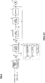
- FIG.5 shows a configuration example of the present invention.
- the steering torque Ts and the vehicle speed Vs are inputted into a torque control section 110, and the torque control section 110 calculates a torque control command value TC based on the steering torque Ts and the vehicle speed Vs.
- a tire-turning steering angle command value At and an actual turning steering angle Ar are inputted into an angle control section 120, and the angle control section 120 calculates an angle control command value AC based on the tire-turning steering angle command value At and the actual turning steering angle Ar.
- the torque control command value TC from the torque control section 110 is inputted into a command value difference calculating section 102 and a switching section 104 in a switching control section 100
- the angle control command value AC from the angle control section 120 is inputted into the command value difference calculating section 102 and the switching section 104 in the switching control section 100.
- a vehicle obstacle avoidance signal Vf as a switching trigger (a logical value is “0” in normal, and a logical value is “1” in avoidance) is inputted into a judging section 101 in the switching control section 100, and the judging section 101 judges whether the vehicle obstacle avoidance signal Vf is varied from “0" to “1", or whether the vehicle obstacle avoidance signal Vf is varied from “1” to “0".
- the judging section 101 judges that the vehicle obstacle avoidance signal Vf is varied from “0” to "1”
- the judging section 101 outputs a judging signal DS2, and the judging signal DS2 is inputted into the switching section 104.
- the judging section 101 judges that the vehicle obstacle avoidance signal Vf is varied from “1” to "0”
- the judging section 101 outputs a judging signal DS1, and the judging signal DS1 is inputted into the command value difference calculating section 102.
- the command value difference calculating section 102 calculates the command value difference CD which is an absolute value of a difference between the torque control command value TC and the angle control command value AC. That is, the command value difference CD is calculated by a following Equation 1.
- command value difference CD
- the command value difference CD is inputted into a gradual-changing time calculating section 103, and the gradual-changing time calculating section 103 calculates a gradual-changing time Tj corresponding to the command value difference CD by using, for example, calculating equations having characteristics A, B or C of Fig.6 .
- gradual ⁇ changing time Tj gradual ⁇ changing time transform coefficient ⁇ command value difference CD
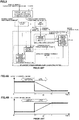
- the characteristic A is an example of linear calculating, and the characteristics B and C are examples of non-linear calculating.
- the gradual-changing time Tj which is calculated at the gradual-changing time calculating section 103, is inputted into the switching section 104, and the switching section 104 switches from the angle control to the torque control by a gradual-changing characteristic (the gradual-changing time Tj) as shown in, for example, FIG.7 . That is, the control mode is the angle control (100%) before a time point t11.
- the switching section 104 switches to the torque control by a linear characteristic until a time point t12 in accordance with the gradual-changing time Tj.
- the control mode is the torque control (100%) after the time point t12.
- An output of the switching section 104 is outputted as a motor command value MC, and the motor command value MC is inputted into a current control system 130.
- a motor 131 for assist is driving-controlled via the current control system 130.
- the judging section 101 judges that the vehicle obstacle avoidance signal Vf is varied from “0" to "1"
- the judging section 101 outputs the judging signal DS2, and the judging signal DS2 is inputted into the switching section 104. Since the switching section 104 has a step characteristic as shown in FIG. 8 , when the judging signal DS2 is inputted at the time point t1, the control mode is instantaneously switched from the torque control (100%) to the angle control (100%).
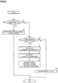
- the judging section 101 judges whether the vehicle obstacle avoidance signal Vf is varied from “0" to “1” or not (Step S1).
- the judging section 101 outputs the judging signal DS2 , and the switching section 104 switches from the torque control to the angle control (Step S2). Thereby, the angle control is performed.
- Step S10 when the judging section 101 does not judge that the vehicle obstacle avoidance signal Vf is varied from “0” to “1”, the judging section 101 judges whether the vehicle obstacle avoidance signal Vf is varied from “1” to “0” or not (Step S10).
- the judging section 101 judges that the vehicle obstacle avoidance signal Vf is varied from “1” to "0”
- the judging section 101 outputs the judging signal DS1, and the judging signal DS1 is inputted into the command value difference calculating section 102.
- the command value difference calculating section 102 calculates the command value difference CD which is the absolute value of the difference between the torque control command value TC and the angle control command value AC (Step S11).
- the calculated command value difference CD is inputted into the gradual-changing time calculating section 103, the gradual-changing time calculating section 103 calculates the gradual-changing time Tj which has a characteristic as shown in FIG. 6 , and is a longer time when the command value difference CD is larger (Step S12).
- the gradual-changing time Tj is inputted into the switching section 104, and the switching section 104 gradually switches from the angle control to the torque control by the gradual-changing process as shown in FIG.7 in accordance with the gradual-changing time Tj (Step S13).
- Step S10 in a case that the vehicle obstacle avoidance signal Vf is not varied from “1" to "0", the present control is maintained (Step S20).
- the vehicle obstacle avoidance signal Vf is used as the logical value "0" in normal and the logical value "1" in avoidance.
- An inverse judging may be used by using the vehicle obstacle avoidance signal Vf as the logical value "1" in normal and the logical value "0" in avoidance.
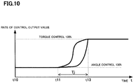
- the characteristic of the gradual-changing process may be a non-linear gradual-changing characteristic as shown in Fig.10 .
Landscapes
- Engineering & Computer Science (AREA)
- Chemical & Material Sciences (AREA)
- Combustion & Propulsion (AREA)
- Transportation (AREA)
- Mechanical Engineering (AREA)
- Physics & Mathematics (AREA)
- Mathematical Physics (AREA)
- Steering Control In Accordance With Driving Conditions (AREA)
- Power Steering Mechanism (AREA)
Abstract
Description
- The present invention relates to an electric power steering apparatus that has an automatic steering mode (a parking assist, an obstacle avoidance, a lane keeping and so on) and a manual steering mode (a normal steering), and applies an assist force by a motor to a steering system of a vehicle, and in particular to the electric power steering apparatus that variably sets a gradual-changing time corresponding to a command value difference between an angle control command value and a torque control command value when switching from an angle control system of the automatic steering mode to a torque control system of the manual steering mode by using a gradual-changing.
- An electric power steering apparatus (EPS) which has a motor control apparatus, and provides a steering system of a vehicle with a steering assist torque (an assist torque) by means of a rotational torque of a motor, applies the steering assist torque to a steering shaft or a rack shaft by means of a transmission mechanism such as gears or a belt through a reduction mechanism. In order to accurately generate the assist torque, such a conventional electric power steering apparatus performs a feedback control of a motor current. The feedback control adj usts a voltage supplied to the motor so that a difference between a steering assist command value (a current command value) and a detected motor current value becomes small, and the adjustment of the voltage applied to the motor is generally performed by an adjustment of a duty of a pulse width modulation (PWM) control.
- A general configuration of the conventional electric power steering apparatus will be described with reference to
FIG.1 . As shown inFig.1 , a column shaft (a steering shaft) 2 connected to a handle (a steering wheel) 1 is connected to steeredwheels reduction gears 3,universal joints pinion mechanism 5, andtie rods hub units column shaft 2 is provided with atorque sensor 10 for detecting a steering torque Ts of thehandle 1, and amotor 20 for assisting a steering force of the handle (the steering wheel) 1 is connected to thecolumn shaft 2 through thereduction gears 3. The electric power is supplied to a control unit (ECU) 30 for controlling the electric power steering apparatus from abattery 13, and an ignition key signal is inputted into thecontrol unit 30 through anignition key 11. Thecontrol unit 30 calculates a steering assist command value of an assist command (a steering assist command) on the basis of the steering torque Ts detected by thetorque sensor 10 and a vehicle speed Vs detected by avehicle speed sensor 12, and controls a current supplied to themotor 20 by means of a voltage control value Vref obtained by performing compensation or the like to the steering assist command value. Asteering angle sensor 14 is not indispensable and may not be provided. It is possible to obtain the steering angle θ from a rotational position sensor which is connected to themotor 20. - A controller area network (CAN) 40 to send/receive various information and signals on the vehicle is connected to the
control unit 30, and it is also possible to receive the vehicle speed Vs from the CAN. Further, a Non-CAN 41 is also possible to connect to thecontrol unit 30, and the Non-CAN 41 sends and receives a communication, analogue/digital signals, electric wave or the like except for the CAN 40. - In such an electric power steering apparatus, the
control unit 30 mainly comprises a CPU (Central Processing Unit) (including an MPU (Micro Processor Unit) and an MCU (Micro Controller Unit)), and general functions performed by programs within the CPU are, for example, shown inFIG.2 . - Functions and operations of the
control unit 30 will be described with reference toFIG.2 . The steering torque Ts from thetorque sensor 10 and the vehicle speed Vs from thevehicle speed sensor 12 are inputted into a current commandvalue calculating section 31. The current commandvalue calculating section 31 calculates a current command value Iref1 based on the steering torque Ts and the vehicle speed Vs using an assist map or the like. The calculated current command value Iref1 is added with a compensation signal CM for improving characteristics from a compensatingsection 34 at an addingsection 32A. The current command value Iref2 after addition is limited of the maximum value thereof at a current limitingsection 33. The current command value Irefm limited of the maximum value is inputted into a subtractingsection 32B, whereat a detected motor current value Im is subtracted from the current command value Irefm. - The subtraction result I (=Irefm-Im) at the subtracting
section 32B is proportional-integral-controlled (PI-controlled) at a PI-control section 35. The voltage control value Vref obtained by the PI-control is inputted into a PWM-control section 36 , whereat a duty thereof is calculated. Themotor 20 is PWM-driven by aninverter 37 with a PWMsignal calculated the duty. The motor current value Im of themotor 20 is detected by a motor current detection means 38 and is inputted into the subtractingsection 32B for the feedback. - The compensating
section 34 adds a self-aligning torque (SAT) 34-3 detected or estimated and an inertia compensation value 34-2 at an adding section 34-4. The addition result is further added with a convergence control value 34-1 at an adding section 34-5. The addition result is inputted into the addingsection 32A as the compensation signal CM, thereby to improve the control characteristics. - In such an electric power steering apparatus, vehicles that are equipped with an automatic steering control mode such as a parking assist function, an obstacle avoidance function, a lane keeping function and so on, and switch between the automatic steering control mode and a manual steering control mode have emerged in recent years. In the vehicles that are equipped with the parking assist function, an automatic steering control that a target steering angle is set based on data such as a camera (an image) and a distance sensor, and an actual steering angle is controlled to follow-up the target steering angle, is performed.
- In the conventional well-known electric power steering apparatus that has a function of the automatic steering mode and the manual steering mode, for example in a parking assist, a back-in parking or a parallel parking is automatically performed by controlling an actuator (a motor) based on a relationship between a traveling distance of the vehicle and a turning steering angle, which is pre-stored. That is, a parking assist apparatus recognizes a parking space from a position sensor such an ultrasonic sensor and outputs a steering angle command value (an angle control command value) to the EPS-side. The EPS position-controls the actual steering angle so as to follow-up the steering angle command value, and then the vehicle is guided into the parking space.
-
FIG. 3 shows a control system of the electric power steering apparatus having the parking assist mode function. Various data from the camera and the position sensor (the ultrasonic sensor or the like) are inputted into a parking-assist-etc. automaticsteering command apparatus 50, a parking-assist steering angle command value θt is inputted into a position control section (an angle control section) 51 in the EPS actuator function via the CAN or the like and a parking-assist performing command is inputted into a parking-assist performingjudging section 52 in the EPS actuator function via the CAN or the like. The actual steering angle θr which is a steering angle signal from a steering angle sensor or an external is inputted into theposition control section 51 and a judging result of the parking-assist performingjudging section 52 is inputted into a torque command value gradual-changingswitching section 54. The steering torque Ts of the EPS sensor is inputted into atorque control section 53 in an EPS power assist function and a steering-assist torque command value Tc from thetorque control section 53 is inputted into the torque command value gradual-changingswitching section 54. A position control torque command value Tp from theposition control section 51 is also inputted into the torque command value gradual-changingswitching section 54. According to a judging result of the parking-assist performingjudging section 52, the steering-assist torque command value Tc and the position control torque command value Tp are switched and s switched result is outputted as the motor torque command value, and the motor is driving-controlled via a current control system. - As well, although the
position control section 51 also actually performs a speed control and forms aposition/speedcontrol section to input a steering angle speed, the here description is limited to the position control for convenience of the explanation. - In this manner, in a case of a normal power assist, a torque control system is used. Meanwhile, in a case of the automatic driving such as the parking assist, the angle control system (the position control system) is used. When switching between the torque control and the angle control, there are problems that switching is not smoothlyperformeddue to a variation of the control torque and that an unintentional assistance torque is occurred due to the torque variation served as a trigger.
- For a conventional system of switching from the angle control (the automatic steering) to the torque control (the manual control), an automatic steering apparatus is disclosed in, for example Japanese Patent No.
3311277 B2 Patent Document 1, as shown in a broken line ofFIG.4A , in a case that a control amount of the actuator (the motor) decreases when switching from the automatic steering control (the angle control) to the torque control, a steering reaction force which a driver receives from the steering wheel is not sharply varied by linearly decreasing the control amount from a value of the automatic steering control to a value of the torque control for passing a predetermined time t0. As shown in the broken line ofFIG.4B , in a case that the control amount increases when switching from the automatic steering control to the torque control, the steering reaction force which the driver receives from the steering wheel is not quickly varied by linearly increasing the control amount from the value of the automatic steering control to the value of the torque control for passing the predetermined time t0. As a result, it is prevented from generating the excessive turning steering angle due to quickly turning the steering wheel and not obtaining the necessary turning steering angle due to slowly turning the steering wheel. - Patent Document 1: Japanese Patent No.
3311277 B2 - However, in the automatic steering apparatus of
Patent Document 1, since a difference between the angle control command value and the torque control command value is not considered at all, in a case that the difference between the angle control command value and the torque control command value is large, there are problems that safety is reduced and the driver feels uncomfortable due to a large torque variation which the driver receives. - The present invention has been developed in view of the above-described circumstances, and an object of the present invention is to provide the electric power steering apparatus that has safety and a high performance in which the uncomfortable feeling is reduced, by being varied a gradual-changing time based on the command value difference between the angle control command value and the torque control command value when the gradual-changing process, in which a control system is switched from the angle control (the automatic steering mode) to the torque control (the manual steering mode), is performed.
- The present invention relates to an electric power steering apparatus that has a torque sensor which detects a steering torque, and a motor control apparatus to control a motor which applies an assist torque, by which steering is assisted, to a steering system of a vehicle, the above-described object of the present invention is achieved by that comprising: a function that switches a control system of the motor between an angle control system to control an angle corresponding to an angle control command value of an automatic steering mode and a torque control system to control a torque corresponding to a torque control command value of a manual steering mode in accordance with a predetermined switching trigger, wherein the electric power steering apparatus variably sets a gradual-changing time corresponding to a command value difference between the angle control command value and the torque control command value when switching from the angle control system to the torque control system by using a gradual-changing.
- The above-described object of the present invention is efficiently achieved by that: wherein the command value difference is an absolute value of a difference between the angle control command value and the torque control command value; or wherein the predetermined switching trigger is a turning-ON or a turning-OFF of an automatic steering command; or wherein the turning-ON or the turning-OFF of the automatic steering command is a command of a parking assist, a command of an obstacle avoidance or a command of a lane keeping; or wherein the predetermined switching trigger is a turning-ON or a turning-OFF of a switching command which is given by an internal judgment of the steering torque; or wherein the gradual-changing time is linearly or non-linearly varied corresponding to the command value difference, or wherein the gradual-changing is performed linearly or non-linearly.
- According to the electric power steering apparatus of the present invention, the gradual-changing time is varied based on the command value difference between the angle control command value and the torque control command value at a time of the gradual-changing process, in which the control system is switched from the angle control of the automatic steering mode (the obstacle avoidance, the parking assist and so on) to the torque control of the manual steering mode, is performed. When the command value difference is larger, the gradual-changing time is set to a longer gradual-changing time and the control system is switched more gradually. Thus, the electric power steering apparatus that has safety and a high performance in which the uncomfortable feeling to the driver is reduced, can be provided.
- In the accompanying drawings:
-
FIG.1 is a configuration diagram illustrating a general outline of an electric power steering apparatus; -
FIG.2 is a block diagram showing a general configuration example of a control system of the electric power steering apparatus; -
FIG.3 is a block diagram showing a configuration example of a control system of the electric power steering apparatus having an automatic steering mode function; -
FIG.4A and FIG.4B are characteristic diagrams showing an operation system of the conventional electric power steering apparatus; -
FIG.5 is a block diagram showing a configuration example (a vehicle obstacle avoidance function) of the present invention; -
FIG. 6 is a characteristic diagram showing a characteristic example of a gradual-changing time calculating section according to the present invention; -
FIG.7 is a timing chart showing an operation example of gradual-changing (linear) according to the present invention; -
FIG.8 is a timing chart showing a switching example from a torque control to an angle control; -
FIG. 9 is a flowchart showing an operation example of the present invention; and -
FIG. 10 is a timing chart showing another operation example of gradual-changing (non-linear) according to the present invention. - In a conventional motor control system according to an electric power steering apparatus, since a command value difference, which is an absolute value of a difference between an angle control command value of an automatic steering mode and a torque control command value of a manual steering mode, is not considered at all, in a case that the command value difference is large, there are problems that safety is reduced and a driver feels uncomfortable due to a large torque variation which the driver receives. In this connection, in the present invention, when, for example, a turning-ON or a turning-OFFof a vehicle obstacle avoidance command, a turning-ON or a turning-OFF of a parking assist command or a turning-ON or a turning-OFF of a switching command which is given by an internal judgment of a steering torque is inputted as a switching trigger of a turning-ON or a turning-OFF of an automatic steering, and a control system is switched from the angle control system of the automatic steering mode to the torque control system of the manual steering mode, steering which has safety and suppresses an uncomfortable feeling is realized by variably setting a gradual-changing time corresponding to the command value difference (when the command value difference is larger, the gradual-changing time is longer).
- For example, in the automatic steering mode for the obstacle avoidance, it is necessary to avoid the obstacle by recognizing the frontward obstacle by means of a camera or a radar, and steering a steering wheel. The control of the electric power steering apparatus is the torque control in normal, and is the angle control in the obstacle avoidance. When the control mode is returned from the obstacle avoidance to the normal control, a gradual-changing time is variably set corresponding to the command value difference.
- Embodiments according to the present invention will be described with reference to the drawings in detail. In the present embodiment, the obstacle avoidance is described as an example of the automatic steering mode. Operations of the parking assist, the lane keeping and the like are similar to that of the obstacle avoidance.
-
FIG.5 shows a configuration example of the present invention. The steering torque Ts and the vehicle speed Vs are inputted into atorque control section 110, and thetorque control section 110 calculates a torque control command value TC based on the steering torque Ts and the vehicle speed Vs. A tire-turning steering angle command value At and an actual turning steering angle Ar are inputted into anangle control section 120, and theangle control section 120 calculates an angle control command value AC based on the tire-turning steering angle command value At and the actual turning steering angle Ar. The torque control command value TC from thetorque control section 110 is inputted into a command valuedifference calculating section 102 and aswitching section 104 in aswitching control section 100, and the angle control command value AC from theangle control section 120 is inputted into the command valuedifference calculating section 102 and theswitching section 104 in the switchingcontrol section 100. - A vehicle obstacle avoidance signal Vf as a switching trigger (a logical value is "0" in normal, and a logical value is "1" in avoidance) is inputted into a
judging section 101 in the switchingcontrol section 100, and thejudging section 101 judges whether the vehicle obstacle avoidance signal Vf is varied from "0" to "1", or whether the vehicle obstacle avoidance signal Vf is varied from "1" to "0". When thejudging section 101 judges that the vehicle obstacle avoidance signal Vf is varied from "0" to "1", the judgingsection 101 outputs a judging signal DS2, and the judging signal DS2 is inputted into theswitching section 104. When thejudging section 101 judges that the vehicle obstacle avoidance signal Vf is varied from "1" to "0", the judgingsection 101 outputs a judging signal DS1, and the judging signal DS1 is inputted into the command valuedifference calculating section 102. - When the judging signal DS1 is inputted into the command value
difference calculating section 102, the command valuedifference calculating section 102 calculates the command value difference CD which is an absolute value of a difference between the torque control command value TC and the angle control command value AC. That is, the command value difference CD is calculated by a followingEquation 1.
time calculating section 103, and the gradual-changingtime calculating section 103 calculates a gradual-changing time Tj corresponding to the command value difference CD by using, for example, calculating equations having characteristics A, B or C ofFig.6 .
- The characteristic A is an example of linear calculating, and the characteristics B and C are examples of non-linear calculating. The gradual-changing time Tj, which is calculated at the gradual-changing
time calculating section 103, is inputted into theswitching section 104, and theswitching section 104 switches from the angle control to the torque control by a gradual-changing characteristic (the gradual-changing time Tj) as shown in, for example,FIG.7 . That is, the control mode is the angle control (100%) before a time point t11. When the vehicle obstacle avoidance signal Vf is varied from "1" to "0" at the time point t11, theswitching section 104 switches to the torque control by a linear characteristic until a time point t12 in accordance with the gradual-changing time Tj. The control mode is the torque control (100%) after the time point t12. - An output of the
switching section 104 is outputted as a motor command value MC, and the motor command value MC is inputted into acurrent control system 130. Amotor 131 for assist is driving-controlled via thecurrent control system 130. - When the
judging section 101 judges that the vehicle obstacle avoidance signal Vf is varied from "0" to "1", the judgingsection 101 outputs the judging signal DS2, and the judging signal DS2 is inputted into theswitching section 104. Since theswitching section 104 has a step characteristic as shown inFIG. 8 , when the judging signal DS2 is inputted at the time point t1, the control mode is instantaneously switched from the torque control (100%) to the angle control (100%). - In such a configuration, an operation example will be described with reference to a flowchart of
FIG.9 . - At first, the judging
section 101 judges whether the vehicle obstacle avoidance signal Vf is varied from "0" to "1" or not (Step S1). When the vehicle obstacle avoidance signal Vf is varied from "0" to "1", the judgingsection 101 outputs the judging signal DS2 , and theswitching section 104 switches from the torque control to the angle control (Step S2). Thereby, the angle control is performed. - In the above Step S1, when the judging
section 101 does not judge that the vehicle obstacle avoidance signal Vf is varied from "0" to "1", the judgingsection 101 judges whether the vehicle obstacle avoidance signal Vf is varied from "1" to "0" or not (Step S10). When thejudging section 101 judges that the vehicle obstacle avoidance signal Vf is varied from "1" to "0", the judgingsection 101 outputs the judging signal DS1, and the judging signal DS1 is inputted into the command valuedifference calculating section 102. Thereby, the command valuedifference calculating section 102 calculates the command value difference CD which is the absolute value of the difference between the torque control command value TC and the angle control command value AC (Step S11). The calculated command value difference CD is inputted into the gradual-changingtime calculating section 103, the gradual-changingtime calculating section 103 calculates the gradual-changing time Tj which has a characteristic as shown inFIG. 6 , and is a longer time when the command value difference CD is larger (Step S12). The gradual-changing time Tj is inputted into theswitching section 104, and theswitching section 104 gradually switches from the angle control to the torque control by the gradual-changing process as shown inFIG.7 in accordance with the gradual-changing time Tj (Step S13). - On the other hand, in the above Step S10, in a case that the vehicle obstacle avoidance signal Vf is not varied from "1" to "0", the present control is maintained (Step S20).
- As described above, the vehicle obstacle avoidance signal Vf is used as the logical value "0" in normal and the logical value "1" in avoidance. An inverse judging may be used by using the vehicle obstacle avoidance signal Vf as the logical value "1" in normal and the logical value "0" in avoidance. The characteristic of the gradual-changing process may be a non-linear gradual-changing characteristic as shown in
Fig.10 . -
- 1
- handle (steering wheel)
- 2
- column shaft (steering shaft, handle shaft)
- 10
- torque sensor
- 12
- vehicle speed sensor
- 13
- battery
- 20
- motor
- 21
- motor driving section
- 30
- control unit (ECU)
- 40
- CAN
- 41
- Non-CAN
- 50
- parking-assist-etc. automatic steering command apparatus
- 51
- position control section
- 52
- parking-assist performing judging section
- 53
- torque control section
- 54
- torque command value gradual-changing switching section
- 100
- switching control section
- 101
- judging section
- 102
- command value difference calculating section
- 103
- gradual-changing time calculating section
- 104
- switching section
- 110
- torque control section
- 120
- angle control section
- 130
- current control system
- 131
- motor
Claims (9)
- An electric power steering apparatus that has a torque sensor which detects a steering torque, and a motor control apparatus to control a motor which applies an assist torque, by which steering is assisted, to a steering system of a vehicle, comprising:a function that switches a control system of said motor between an angle control system to control an angle corresponding to an angle control command value of an automatic steering mode and a torque control system to control a torque corresponding to a torque control command value of a manual steering mode in accordance with a predetermined switching trigger,wherein said electric power steering apparatus variably sets a gradual-changing time corresponding to a command value difference between said angle control command value and said torque control command value when switching from said angle control system to said torque control system by using a gradual-changing.
- The electric power steering apparatus according to Claim 1, wherein said command value difference is an absolute value of a difference between said angle control command value and said torque control command value.
- The electric power steering apparatus according to Claim 1 or 2 , wherein said predetermined switching trigger is a turning-ON or a turning-OFF of an automatic steering command.
- The electric power steering apparatus according to Claim 3, wherein said turning-ON or said turning-OFF of said automatic steering command is a command of a parking assist, a command of an obstacle avoidance or a command of a lane keeping.
- The electric power steering apparatus according to Claim 1 or 2 , wherein saidpredetermined switching trigger is a turning-ON or a turning-OFF of a switching command which is given by an internal judgment of said steering torque.
- The electric power steering apparatus according to any one of Claims 1 to 5, wherein said gradual - changing time is linearly varied corresponding to said command value difference.
- The electric power steering apparatus according to any one of Claims 1 to 5, wherein said gradual-changing time is non-linearly varied corresponding to said command value difference.
- The electric power steering apparatus according to any one of Claims 1 to 7, wherein said gradual-changing is performed linearly.
- The electric power steering apparatus according to any one of Claims 1 to 7, wherein said gradual-changing is performed non-linearly.
Applications Claiming Priority (2)
| Application Number | Priority Date | Filing Date | Title |
|---|---|---|---|
| JP2015119727 | 2015-06-12 | ||
| PCT/JP2016/067179 WO2016199839A1 (en) | 2015-06-12 | 2016-06-09 | Electric power steering device |
Publications (3)
| Publication Number | Publication Date |
|---|---|
| EP3266678A1 true EP3266678A1 (en) | 2018-01-10 |
| EP3266678A4 EP3266678A4 (en) | 2018-10-10 |
| EP3266678B1 EP3266678B1 (en) | 2019-10-23 |
Family
ID=57503623
Family Applications (1)
| Application Number | Title | Priority Date | Filing Date |
|---|---|---|---|
| EP16807545.5A Active EP3266678B1 (en) | 2015-06-12 | 2016-06-09 | Electric power steering device |
Country Status (5)
| Country | Link |
|---|---|
| US (1) | US10059369B2 (en) |
| EP (1) | EP3266678B1 (en) |
| JP (1) | JP6237958B2 (en) |
| CN (1) | CN107848570B (en) |
| WO (1) | WO2016199839A1 (en) |
Cited By (1)
| Publication number | Priority date | Publication date | Assignee | Title |
|---|---|---|---|---|
| EP3495245A1 (en) * | 2017-11-29 | 2019-06-12 | Jtekt Corporation | Vehicle steering system |
Families Citing this family (14)
| Publication number | Priority date | Publication date | Assignee | Title |
|---|---|---|---|---|
| WO2016088704A1 (en) * | 2014-12-02 | 2016-06-09 | 日本精工株式会社 | Electric power steering device |
| KR102335985B1 (en) * | 2017-07-04 | 2021-12-07 | 현대자동차주식회사 | Apparatus for controlling steering angle, lane keeping assist system having the same and method thereof |
| JP7236038B2 (en) * | 2017-11-30 | 2023-03-09 | 株式会社ジェイテクト | vehicle steering system |
| JP7129003B2 (en) * | 2018-09-21 | 2022-09-01 | 株式会社ジェイテクト | motor controller |
| JP2020082915A (en) * | 2018-11-20 | 2020-06-04 | 株式会社ジェイテクト | Steering apparatus and motor control method in steering apparatus |
| JP7175577B2 (en) * | 2018-11-30 | 2022-11-21 | ダイハツ工業株式会社 | vehicle control system |
| CN111547050B (en) * | 2019-01-24 | 2021-07-16 | 北汽福田汽车股份有限公司 | Method, device and system for switching transverse control modes and automobile |
| KR102660394B1 (en) * | 2019-03-11 | 2024-04-24 | 에이치엘만도 주식회사 | Device for controlling overlay in electronic power steering system and method thereof |
| JP2020147213A (en) * | 2019-03-14 | 2020-09-17 | トヨタ自動車株式会社 | Control device of automatic driving system and control method by the device |
| US11066025B2 (en) * | 2019-03-27 | 2021-07-20 | Jack Chen | Electric vehicle drive system and operation method of the same |
| JP7205373B2 (en) * | 2019-05-07 | 2023-01-17 | 株式会社デンソー | Rotating electric machine controller |
| KR102718298B1 (en) * | 2020-04-17 | 2024-10-17 | 현대모비스 주식회사 | Apparatus and method for controlling motor driven power steering system of vehicle |
| KR102341112B1 (en) * | 2020-04-23 | 2021-12-21 | 현대모비스 주식회사 | Apparatus for controlling motor driven power steering system and method thereof |
| CN118317901A (en) * | 2021-12-14 | 2024-07-09 | 三菱电机株式会社 | Electric power steering |
Family Cites Families (8)
| Publication number | Priority date | Publication date | Assignee | Title |
|---|---|---|---|---|
| JP2998864B2 (en) * | 1991-12-25 | 2000-01-17 | アイシン精機株式会社 | Automatic vehicle steering control device |
| JPH10309961A (en) * | 1997-05-12 | 1998-11-24 | Toyota Motor Corp | Automatic driving vehicle control device |
| JP3311277B2 (en) * | 1997-09-05 | 2002-08-05 | 本田技研工業株式会社 | Automatic vehicle steering system |
| JPH11286280A (en) * | 1998-04-03 | 1999-10-19 | Mitsubishi Electric Corp | Automatic driving control device for vehicles |
| JP4057955B2 (en) | 2003-05-28 | 2008-03-05 | 本田技研工業株式会社 | Automatic vehicle steering system |
| JP4816248B2 (en) * | 2006-05-23 | 2011-11-16 | 日産自動車株式会社 | Driving assistance device for vehicle |
| JP4287452B2 (en) * | 2006-09-12 | 2009-07-01 | 本田技研工業株式会社 | Automatic vehicle steering system |
| US9623899B2 (en) * | 2013-02-07 | 2017-04-18 | Nsk Ltd. | Electric power steering apparatus |
-
2016
- 2016-06-09 JP JP2017523687A patent/JP6237958B2/en not_active Expired - Fee Related
- 2016-06-09 WO PCT/JP2016/067179 patent/WO2016199839A1/en not_active Ceased
- 2016-06-09 EP EP16807545.5A patent/EP3266678B1/en active Active
- 2016-06-09 US US15/571,578 patent/US10059369B2/en not_active Expired - Fee Related
- 2016-06-09 CN CN201680032746.8A patent/CN107848570B/en active Active
Cited By (1)
| Publication number | Priority date | Publication date | Assignee | Title |
|---|---|---|---|---|
| EP3495245A1 (en) * | 2017-11-29 | 2019-06-12 | Jtekt Corporation | Vehicle steering system |
Also Published As
| Publication number | Publication date |
|---|---|
| US20180154929A1 (en) | 2018-06-07 |
| JP6237958B2 (en) | 2017-11-29 |
| CN107848570A (en) | 2018-03-27 |
| WO2016199839A1 (en) | 2016-12-15 |
| US10059369B2 (en) | 2018-08-28 |
| JPWO2016199839A1 (en) | 2017-12-14 |
| EP3266678B1 (en) | 2019-10-23 |
| CN107848570B (en) | 2019-03-26 |
| EP3266678A4 (en) | 2018-10-10 |
Similar Documents
| Publication | Publication Date | Title |
|---|---|---|
| EP3266678B1 (en) | Electric power steering device | |
| JP6519695B2 (en) | Electric power steering device | |
| US11097770B2 (en) | Electric power steering apparatus | |
| EP3459825B1 (en) | Electric power steering device | |
| EP3210855B1 (en) | Electric power steering device | |
| EP3434559A1 (en) | Electrical power steering device | |
| EP3254933B1 (en) | Electric power steering device | |
| EP3162662B1 (en) | Electric power-steering device | |
| US10214232B2 (en) | Electric power steering apparatus | |
| CN112805203A (en) | Electric power steering control device |
Legal Events
| Date | Code | Title | Description |
|---|---|---|---|
| STAA | Information on the status of an ep patent application or granted ep patent |
Free format text: STATUS: THE INTERNATIONAL PUBLICATION HAS BEEN MADE |
|
| PUAI | Public reference made under article 153(3) epc to a published international application that has entered the european phase |
Free format text: ORIGINAL CODE: 0009012 |
|
| STAA | Information on the status of an ep patent application or granted ep patent |
Free format text: STATUS: REQUEST FOR EXAMINATION WAS MADE |
|
| 17P | Request for examination filed |
Effective date: 20171005 |
|
| AK | Designated contracting states |
Kind code of ref document: A1 Designated state(s): AL AT BE BG CH CY CZ DE DK EE ES FI FR GB GR HR HU IE IS IT LI LT LU LV MC MK MT NL NO PL PT RO RS SE SI SK SM TR |
|
| AX | Request for extension of the european patent |
Extension state: BA ME |
|
| DAV | Request for validation of the european patent (deleted) | ||
| DAX | Request for extension of the european patent (deleted) | ||
| A4 | Supplementary search report drawn up and despatched |
Effective date: 20180906 |
|
| RIC1 | Information provided on ipc code assigned before grant |
Ipc: B62D 101/00 20060101ALI20180901BHEP Ipc: B62D 137/00 20060101ALI20180901BHEP Ipc: B62D 119/00 20060101ALI20180901BHEP Ipc: B62D 6/00 20060101AFI20180901BHEP Ipc: B62D 113/00 20060101ALI20180901BHEP |
|
| GRAP | Despatch of communication of intention to grant a patent |
Free format text: ORIGINAL CODE: EPIDOSNIGR1 |
|
| STAA | Information on the status of an ep patent application or granted ep patent |
Free format text: STATUS: GRANT OF PATENT IS INTENDED |
|
| INTG | Intention to grant announced |
Effective date: 20190712 |
|
| GRAS | Grant fee paid |
Free format text: ORIGINAL CODE: EPIDOSNIGR3 |
|
| GRAA | (expected) grant |
Free format text: ORIGINAL CODE: 0009210 |
|
| STAA | Information on the status of an ep patent application or granted ep patent |
Free format text: STATUS: THE PATENT HAS BEEN GRANTED |
|
| AK | Designated contracting states |
Kind code of ref document: B1 Designated state(s): AL AT BE BG CH CY CZ DE DK EE ES FI FR GB GR HR HU IE IS IT LI LT LU LV MC MK MT NL NO PL PT RO RS SE SI SK SM TR |
|
| REG | Reference to a national code |
Ref country code: GB Ref legal event code: FG4D |
|
| REG | Reference to a national code |
Ref country code: CH Ref legal event code: EP |
|
| REG | Reference to a national code |
Ref country code: IE Ref legal event code: FG4D |
|
| REG | Reference to a national code |
Ref country code: DE Ref legal event code: R096 Ref document number: 602016023065 Country of ref document: DE |
|
| REG | Reference to a national code |
Ref country code: AT Ref legal event code: REF Ref document number: 1193332 Country of ref document: AT Kind code of ref document: T Effective date: 20191115 |
|
| REG | Reference to a national code |
Ref country code: NL Ref legal event code: MP Effective date: 20191023 |
|
| REG | Reference to a national code |
Ref country code: LT Ref legal event code: MG4D |
|
| PG25 | Lapsed in a contracting state [announced via postgrant information from national office to epo] |
Ref country code: FI Free format text: LAPSE BECAUSE OF FAILURE TO SUBMIT A TRANSLATION OF THE DESCRIPTION OR TO PAY THE FEE WITHIN THE PRESCRIBED TIME-LIMIT Effective date: 20191023 Ref country code: GR Free format text: LAPSE BECAUSE OF FAILURE TO SUBMIT A TRANSLATION OF THE DESCRIPTION OR TO PAY THE FEE WITHIN THE PRESCRIBED TIME-LIMIT Effective date: 20200124 Ref country code: NO Free format text: LAPSE BECAUSE OF FAILURE TO SUBMIT A TRANSLATION OF THE DESCRIPTION OR TO PAY THE FEE WITHIN THE PRESCRIBED TIME-LIMIT Effective date: 20200123 Ref country code: PL Free format text: LAPSE BECAUSE OF FAILURE TO SUBMIT A TRANSLATION OF THE DESCRIPTION OR TO PAY THE FEE WITHIN THE PRESCRIBED TIME-LIMIT Effective date: 20191023 Ref country code: NL Free format text: LAPSE BECAUSE OF FAILURE TO SUBMIT A TRANSLATION OF THE DESCRIPTION OR TO PAY THE FEE WITHIN THE PRESCRIBED TIME-LIMIT Effective date: 20191023 Ref country code: LT Free format text: LAPSE BECAUSE OF FAILURE TO SUBMIT A TRANSLATION OF THE DESCRIPTION OR TO PAY THE FEE WITHIN THE PRESCRIBED TIME-LIMIT Effective date: 20191023 Ref country code: LV Free format text: LAPSE BECAUSE OF FAILURE TO SUBMIT A TRANSLATION OF THE DESCRIPTION OR TO PAY THE FEE WITHIN THE PRESCRIBED TIME-LIMIT Effective date: 20191023 Ref country code: SE Free format text: LAPSE BECAUSE OF FAILURE TO SUBMIT A TRANSLATION OF THE DESCRIPTION OR TO PAY THE FEE WITHIN THE PRESCRIBED TIME-LIMIT Effective date: 20191023 Ref country code: PT Free format text: LAPSE BECAUSE OF FAILURE TO SUBMIT A TRANSLATION OF THE DESCRIPTION OR TO PAY THE FEE WITHIN THE PRESCRIBED TIME-LIMIT Effective date: 20200224 Ref country code: BG Free format text: LAPSE BECAUSE OF FAILURE TO SUBMIT A TRANSLATION OF THE DESCRIPTION OR TO PAY THE FEE WITHIN THE PRESCRIBED TIME-LIMIT Effective date: 20200123 |
|
| PG25 | Lapsed in a contracting state [announced via postgrant information from national office to epo] |
Ref country code: IS Free format text: LAPSE BECAUSE OF FAILURE TO SUBMIT A TRANSLATION OF THE DESCRIPTION OR TO PAY THE FEE WITHIN THE PRESCRIBED TIME-LIMIT Effective date: 20200224 Ref country code: RS Free format text: LAPSE BECAUSE OF FAILURE TO SUBMIT A TRANSLATION OF THE DESCRIPTION OR TO PAY THE FEE WITHIN THE PRESCRIBED TIME-LIMIT Effective date: 20191023 Ref country code: HR Free format text: LAPSE BECAUSE OF FAILURE TO SUBMIT A TRANSLATION OF THE DESCRIPTION OR TO PAY THE FEE WITHIN THE PRESCRIBED TIME-LIMIT Effective date: 20191023 |
|
| PG25 | Lapsed in a contracting state [announced via postgrant information from national office to epo] |
Ref country code: AL Free format text: LAPSE BECAUSE OF FAILURE TO SUBMIT A TRANSLATION OF THE DESCRIPTION OR TO PAY THE FEE WITHIN THE PRESCRIBED TIME-LIMIT Effective date: 20191023 |
|
| REG | Reference to a national code |
Ref country code: DE Ref legal event code: R097 Ref document number: 602016023065 Country of ref document: DE |
|
| PG2D | Information on lapse in contracting state deleted |
Ref country code: IS |
|
| PG25 | Lapsed in a contracting state [announced via postgrant information from national office to epo] |
Ref country code: ES Free format text: LAPSE BECAUSE OF FAILURE TO SUBMIT A TRANSLATION OF THE DESCRIPTION OR TO PAY THE FEE WITHIN THE PRESCRIBED TIME-LIMIT Effective date: 20191023 Ref country code: DK Free format text: LAPSE BECAUSE OF FAILURE TO SUBMIT A TRANSLATION OF THE DESCRIPTION OR TO PAY THE FEE WITHIN THE PRESCRIBED TIME-LIMIT Effective date: 20191023 Ref country code: EE Free format text: LAPSE BECAUSE OF FAILURE TO SUBMIT A TRANSLATION OF THE DESCRIPTION OR TO PAY THE FEE WITHIN THE PRESCRIBED TIME-LIMIT Effective date: 20191023 Ref country code: CZ Free format text: LAPSE BECAUSE OF FAILURE TO SUBMIT A TRANSLATION OF THE DESCRIPTION OR TO PAY THE FEE WITHIN THE PRESCRIBED TIME-LIMIT Effective date: 20191023 Ref country code: RO Free format text: LAPSE BECAUSE OF FAILURE TO SUBMIT A TRANSLATION OF THE DESCRIPTION OR TO PAY THE FEE WITHIN THE PRESCRIBED TIME-LIMIT Effective date: 20191023 Ref country code: IS Free format text: LAPSE BECAUSE OF FAILURE TO SUBMIT A TRANSLATION OF THE DESCRIPTION OR TO PAY THE FEE WITHIN THE PRESCRIBED TIME-LIMIT Effective date: 20200223 |
|
| REG | Reference to a national code |
Ref country code: AT Ref legal event code: MK05 Ref document number: 1193332 Country of ref document: AT Kind code of ref document: T Effective date: 20191023 |
|
| PLBE | No opposition filed within time limit |
Free format text: ORIGINAL CODE: 0009261 |
|
| STAA | Information on the status of an ep patent application or granted ep patent |
Free format text: STATUS: NO OPPOSITION FILED WITHIN TIME LIMIT |
|
| PG25 | Lapsed in a contracting state [announced via postgrant information from national office to epo] |
Ref country code: SK Free format text: LAPSE BECAUSE OF FAILURE TO SUBMIT A TRANSLATION OF THE DESCRIPTION OR TO PAY THE FEE WITHIN THE PRESCRIBED TIME-LIMIT Effective date: 20191023 Ref country code: IT Free format text: LAPSE BECAUSE OF FAILURE TO SUBMIT A TRANSLATION OF THE DESCRIPTION OR TO PAY THE FEE WITHIN THE PRESCRIBED TIME-LIMIT Effective date: 20191023 Ref country code: SM Free format text: LAPSE BECAUSE OF FAILURE TO SUBMIT A TRANSLATION OF THE DESCRIPTION OR TO PAY THE FEE WITHIN THE PRESCRIBED TIME-LIMIT Effective date: 20191023 |
|
| 26N | No opposition filed |
Effective date: 20200724 |
|
| PG25 | Lapsed in a contracting state [announced via postgrant information from national office to epo] |
Ref country code: SI Free format text: LAPSE BECAUSE OF FAILURE TO SUBMIT A TRANSLATION OF THE DESCRIPTION OR TO PAY THE FEE WITHIN THE PRESCRIBED TIME-LIMIT Effective date: 20191023 Ref country code: AT Free format text: LAPSE BECAUSE OF FAILURE TO SUBMIT A TRANSLATION OF THE DESCRIPTION OR TO PAY THE FEE WITHIN THE PRESCRIBED TIME-LIMIT Effective date: 20191023 |
|
| REG | Reference to a national code |
Ref country code: DE Ref legal event code: R119 Ref document number: 602016023065 Country of ref document: DE |
|
| PG25 | Lapsed in a contracting state [announced via postgrant information from national office to epo] |
Ref country code: MC Free format text: LAPSE BECAUSE OF FAILURE TO SUBMIT A TRANSLATION OF THE DESCRIPTION OR TO PAY THE FEE WITHIN THE PRESCRIBED TIME-LIMIT Effective date: 20191023 |
|
| REG | Reference to a national code |
Ref country code: CH Ref legal event code: PL |
|
| GBPC | Gb: european patent ceased through non-payment of renewal fee |
Effective date: 20200609 |
|
| PG25 | Lapsed in a contracting state [announced via postgrant information from national office to epo] |
Ref country code: LU Free format text: LAPSE BECAUSE OF NON-PAYMENT OF DUE FEES Effective date: 20200609 |
|
| REG | Reference to a national code |
Ref country code: BE Ref legal event code: MM Effective date: 20200630 |
|
| PG25 | Lapsed in a contracting state [announced via postgrant information from national office to epo] |
Ref country code: LI Free format text: LAPSE BECAUSE OF NON-PAYMENT OF DUE FEES Effective date: 20200630 Ref country code: CH Free format text: LAPSE BECAUSE OF NON-PAYMENT OF DUE FEES Effective date: 20200630 Ref country code: IE Free format text: LAPSE BECAUSE OF NON-PAYMENT OF DUE FEES Effective date: 20200609 Ref country code: GB Free format text: LAPSE BECAUSE OF NON-PAYMENT OF DUE FEES Effective date: 20200609 Ref country code: FR Free format text: LAPSE BECAUSE OF NON-PAYMENT OF DUE FEES Effective date: 20200630 |
|
| PG25 | Lapsed in a contracting state [announced via postgrant information from national office to epo] |
Ref country code: BE Free format text: LAPSE BECAUSE OF NON-PAYMENT OF DUE FEES Effective date: 20200630 Ref country code: DE Free format text: LAPSE BECAUSE OF NON-PAYMENT OF DUE FEES Effective date: 20210101 |
|
| PG25 | Lapsed in a contracting state [announced via postgrant information from national office to epo] |
Ref country code: TR Free format text: LAPSE BECAUSE OF FAILURE TO SUBMIT A TRANSLATION OF THE DESCRIPTION OR TO PAY THE FEE WITHIN THE PRESCRIBED TIME-LIMIT Effective date: 20191023 Ref country code: MT Free format text: LAPSE BECAUSE OF FAILURE TO SUBMIT A TRANSLATION OF THE DESCRIPTION OR TO PAY THE FEE WITHIN THE PRESCRIBED TIME-LIMIT Effective date: 20191023 Ref country code: CY Free format text: LAPSE BECAUSE OF FAILURE TO SUBMIT A TRANSLATION OF THE DESCRIPTION OR TO PAY THE FEE WITHIN THE PRESCRIBED TIME-LIMIT Effective date: 20191023 |
|
| PG25 | Lapsed in a contracting state [announced via postgrant information from national office to epo] |
Ref country code: MK Free format text: LAPSE BECAUSE OF FAILURE TO SUBMIT A TRANSLATION OF THE DESCRIPTION OR TO PAY THE FEE WITHIN THE PRESCRIBED TIME-LIMIT Effective date: 20191023 |