EP3266617A1 - Sheet detection device and printer - Google Patents
Sheet detection device and printer Download PDFInfo
- Publication number
- EP3266617A1 EP3266617A1 EP17178968.8A EP17178968A EP3266617A1 EP 3266617 A1 EP3266617 A1 EP 3266617A1 EP 17178968 A EP17178968 A EP 17178968A EP 3266617 A1 EP3266617 A1 EP 3266617A1
- Authority
- EP
- European Patent Office
- Prior art keywords
- sheet
- guide
- opening
- transport direction
- cover
- Prior art date
- Legal status (The legal status is an assumption and is not a legal conclusion. Google has not performed a legal analysis and makes no representation as to the accuracy of the status listed.)
- Withdrawn
Links
Images




Classifications
-
- B—PERFORMING OPERATIONS; TRANSPORTING
- B41—PRINTING; LINING MACHINES; TYPEWRITERS; STAMPS
- B41J—TYPEWRITERS; SELECTIVE PRINTING MECHANISMS, i.e. MECHANISMS PRINTING OTHERWISE THAN FROM A FORME; CORRECTION OF TYPOGRAPHICAL ERRORS
- B41J13/00—Devices or arrangements of selective printing mechanisms, e.g. ink-jet printers or thermal printers, specially adapted for supporting or handling copy material in short lengths, e.g. sheets
- B41J13/0009—Devices or arrangements of selective printing mechanisms, e.g. ink-jet printers or thermal printers, specially adapted for supporting or handling copy material in short lengths, e.g. sheets control of the transport of the copy material
-
- B—PERFORMING OPERATIONS; TRANSPORTING
- B41—PRINTING; LINING MACHINES; TYPEWRITERS; STAMPS
- B41J—TYPEWRITERS; SELECTIVE PRINTING MECHANISMS, i.e. MECHANISMS PRINTING OTHERWISE THAN FROM A FORME; CORRECTION OF TYPOGRAPHICAL ERRORS
- B41J11/00—Devices or arrangements of selective printing mechanisms, e.g. ink-jet printers or thermal printers, for supporting or handling copy material in sheet or web form
- B41J11/0095—Detecting means for copy material, e.g. for detecting or sensing presence of copy material or its leading or trailing end
-
- B—PERFORMING OPERATIONS; TRANSPORTING
- B41—PRINTING; LINING MACHINES; TYPEWRITERS; STAMPS
- B41J—TYPEWRITERS; SELECTIVE PRINTING MECHANISMS, i.e. MECHANISMS PRINTING OTHERWISE THAN FROM A FORME; CORRECTION OF TYPOGRAPHICAL ERRORS
- B41J11/00—Devices or arrangements of selective printing mechanisms, e.g. ink-jet printers or thermal printers, for supporting or handling copy material in sheet or web form
- B41J11/36—Blanking or long feeds; Feeding to a particular line, e.g. by rotation of platen or feed roller
- B41J11/42—Controlling printing material conveyance for accurate alignment of the printing material with the printhead; Print registering
- B41J11/46—Controlling printing material conveyance for accurate alignment of the printing material with the printhead; Print registering by marks or formations on the paper being fed
-
- B—PERFORMING OPERATIONS; TRANSPORTING
- B41—PRINTING; LINING MACHINES; TYPEWRITERS; STAMPS
- B41J—TYPEWRITERS; SELECTIVE PRINTING MECHANISMS, i.e. MECHANISMS PRINTING OTHERWISE THAN FROM A FORME; CORRECTION OF TYPOGRAPHICAL ERRORS
- B41J13/00—Devices or arrangements of selective printing mechanisms, e.g. ink-jet printers or thermal printers, specially adapted for supporting or handling copy material in short lengths, e.g. sheets
- B41J13/10—Sheet holders, retainers, movable guides, or stationary guides
-
- B—PERFORMING OPERATIONS; TRANSPORTING
- B41—PRINTING; LINING MACHINES; TYPEWRITERS; STAMPS
- B41J—TYPEWRITERS; SELECTIVE PRINTING MECHANISMS, i.e. MECHANISMS PRINTING OTHERWISE THAN FROM A FORME; CORRECTION OF TYPOGRAPHICAL ERRORS
- B41J15/00—Devices or arrangements of selective printing mechanisms, e.g. ink-jet printers or thermal printers, specially adapted for supporting or handling copy material in continuous form, e.g. webs
- B41J15/04—Supporting, feeding, or guiding devices; Mountings for web rolls or spindles
- B41J15/046—Supporting, feeding, or guiding devices; Mountings for web rolls or spindles for the guidance of continuous copy material, e.g. for preventing skewed conveyance of the continuous copy material
-
- B—PERFORMING OPERATIONS; TRANSPORTING
- B41—PRINTING; LINING MACHINES; TYPEWRITERS; STAMPS
- B41J—TYPEWRITERS; SELECTIVE PRINTING MECHANISMS, i.e. MECHANISMS PRINTING OTHERWISE THAN FROM A FORME; CORRECTION OF TYPOGRAPHICAL ERRORS
- B41J3/00—Typewriters or selective printing or marking mechanisms characterised by the purpose for which they are constructed
- B41J3/407—Typewriters or selective printing or marking mechanisms characterised by the purpose for which they are constructed for marking on special material
- B41J3/4075—Tape printers; Label printers
Definitions
- the present invention relates to a sheet detection device and a printer including the sheet detection device.
- the sheet detection device includes a sheet guide having a guide surface through which a sheet passes.
- the guide surface is provided with an opening through which an optical sensor as a sheet detector is exposed.
- printers that print on label paper in which labels are stuck on roll long mount paper at predetermined intervals or on tag paper in which tags are continuously formed on accordion-fold long paper has been known.
- a sheet detection device that detects a predetermined position of paper is installed in the printers.
- a sheet detection device including a sheet guide disposed between a sheet feeding opening into which a sheet is inserted and a printing mechanism that prints on a sheet has been taught by JP2012-148884A , JP2003-146482A , JP H03-102547U1 , and JP S63-063452U1 .
- This sheet guide includes a guide surface provided with an opening through which an optical sensor as a sheet detector is exposed.
- the guide surface of the sheet guide is covered by an openable and closable cover.
- the sheet When a sheet is inserted from the sheet feeding opening toward the printing mechanism with the cover being closed, the sheet may be caught by an end portion of the opening provided in the guide surface or by the sheet detector.
- An object of the present invention is to provide a sheet detection device and a printer in which a sheet inserted from a sheet feeding opening smoothly reaches a printing mechanism without being caught on the way to the printing mechanism with the cover being closed.
- an aspect of the present invention provides a sheet detection device including a sheet guide disposed between a sheet feeding opening into which a sheet is inserted and a printing mechanism of printing on the sheet, the sheet guide including a guide surface through which the sheet passes, a sheet detector including an optical sensor that detects a predetermined position of the sheet, an opening formed in the guide surface, the sheet detector being disposed inside the opening and the optical sensor being exposed through the opening, and a transparent guide cover provided in the guide surface to cover at least a first border position between the sheet detector and the opening on an upstream side in a sheet transport direction.
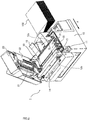
- Figs. 1 to 3 are perspective views of a printer according to the Embodiment.
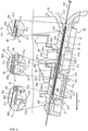
- Fig. 4 is a sectional view along an A-A line in Fig. 1 . The entire configurations of the printer according to the Embodiment are described with reference to Figs. 1 to 4 .
- a printer 1 according to the Embodiment is a thermal printer that prints with a printing method (thermal method) of inducing chemical reaction by heating a sheet 100 in which special drug is applied on a printing surface with a thermal head 21 for coloring.
- This printer 1 includes a main body 10 and a cover 20 that covers a top portion of the main body 10. The cover 20 laterally rotates as illustrated in Figs. 2 and 3 by pressing an opening and closing button 11 provided in the main body 10.
- This printer 1 is used with the cover 20 being closed. As illustrated in Fig. 4 , the sheet 100 is fed from a sheet feeding opening 12a formed in the border between the main body 10 and the cover 20. After the sheet 100 is printed in a region covered by the cover 20, the printed sheet 100 is discharged from a sheet discharging opening 12b formed in the border between the main body 10 and the cover 20.
- a direction from the sheet feeding opening 12a to the sheet discharging opening 12b is defined as a sheet transport direction X.
- "Upstream side in sheet transport direction X" is defined as a side closer to the sheet feeding opening 12a and "downstream side in sheet transport direction X" is defined as a side closer to the sheet discharging opening 12b.
- the maintenance of the printer 1 such as checking or exchanging of components disposed in the main body 10 and the cover 20 is performed with the cover 20 being open.
- the sheet 100 is accordion-fold long tag paper on which a plurality of marks (black marks) for positioning is previously printed at regular intervals.
- the main body 10 is provided with a platen roller 13, an automatic cutter unit 14, and a sheet insertion guide 15.
- the platen roller 13 is rotatably held in the main body 10.
- the platen roller 13 faces the thermal head 21 to press the sheet 100 from the underneath relative to the thermal head 21.
- the sheet 100 is thereby sandwiched by the thermal head 21 and the platen roller 13 when printing.
- the platen roller 13 rotates with the sheet 100 being sandwiched between the thermal head 21 and the platen roller 13, the sheet 100 is transported.
- the automatic cutter unit 14 is disposed between the platen roller 13 and the sheet discharging opening 12b, and cuts the sheet 100 transported from the platen roller 13 in a predetermined position.
- the sheet insertion guide 15 is a tapered frame, and regulates the feeding position of the sheet 100 by inserting the tapered end into the sheet feeding opening 12a.
- the thermal head 21 is provided inside the cover 20 to face the platen roller 13 in the main body 10.
- An operation unit 22 including a plurality of operation buttons 22a and a liquid crystal display screen 22b is provided in a front surface of the cover 20 (see Fig. 1 ).
- the thermal head 21 is a printing head including small heating elements arranged in a line, and prints characters or pictures on the sheet 100 by heating the heating elements according to data.
- the sheet 100 reacts by heat.
- the thermal head 21 and the platen roller 13 configure a printing mechanism of printing on the sheet 100.
- the printing mechanism of the Embodiment includes a transport operation as the sheet 100 is transported by the rotation of the platen roller 13.
- a sheet detection device 30 that detects a predetermined position of the sheet 100 is installed in the printer 1. Note that "predetermined position of sheet 100" is a position of a positioning mark which is previously printed on the sheet 100.
- the sheet detection device 30 is disposed between the sheet feeding opening 12a and the printing mechanism configured by the platen roller 13 and the thermal head 21.
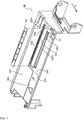
- Figs. 5 , 6 illustrate a lower sheet guide of the sheet detection device according to the Embodiment.
- Figs. 7 , 8 illustrate an upper sheet guide of the sheet detection device according to the Embodiment.
- Fig. 9 is an enlarged view of a main portion of Fig. 4 including the lower sheet guide and the upper sheet guide of the sheet detection device according to the Embodiment.
- the detailed configurations of the sheet detection device according to the Embodiment are described with reference to Figs. 5 to 9 .
- the sheet detection device 30 includes a lower sheet guide 31 (sheet guide), an upper sheet guide 32 (sheet guide), a lower sheet detection unit 33 (sheet detector), an upper sheet detection unit 34 (sheet detector), and a guide cover 35.
- the lower sheet guide 31 is disposed in an upper portion of the main body 10, and has a lower guide surface 31a facing a rear surface of the sheet 100.
- the sheet 100 passes above the lower guide surface 31a (see Fig. 9 ).
- a lower recess 31b (recess), a slot 31c, a dent 31d for a scale, and a hole 31x for a set screw are formed in the lower guide surface 31a of the lower sheet guide 31.
- the lower recess 31 b is zoned by a step 31e formed in the lower guide surface 31a, and is a region lower than the lower guide surface 31a on an upstream side of the step 31e in the sheet transport direction X.
- the step 31e has a height H1 greater than a thickness of the guide cover 35 (in this case, the total thickness W1 of the thickness of the guide cover 35 and the thickness of a double-faced tape 37).
- the depth of the lower recess 31b which is determined by the height H1 of the step 31e is greater than the thickness of the guide cover 35.
- the lower recess 31b includes a recess surface 31f with the step 31e as a border.
- the slot 31c penetrates through the lower recess 31b, and linearly extends along a direction orthogonal to the sheet transport direction X.
- An opening of the slot 31c on the lower guide surface 31a is defined as an opening 31 g (lower opening) through which the after-described first optical sensor 33b of the lower sheet detection unit 33 is exposed.
- a wave portion 31h having an irregularity along the extending direction of the slot 31c is formed in both inner surfaces of the slot 31c extending in the direction orthogonal to the sheet transport direction X.
- the wave portion 31h includes convex portions each projecting in the sheet transport direction X and concave portions. The convex portions and the concave portions are alternately arranged (see Fig. 6 ).
- the dent 31d for a scale is formed in the lower recess 31b by further denting the recess surface 31f.
- the dent 31d for a scale is positioned between the step 31e and the slot 31c, and is adjacent to an end portion 36A of the opening 31g on the upstream side in the sheet transport direction X in the Embodiment.
- the dent 31d for a scale linearly extends along the direction orthogonal to the sheet transport direction X.
- a scale sheet 31j (scale display) is stuck inside the dent 31d for a scale.
- the hole 31x for a set screw is a hole through which a not-shown set screw for fixing the lower sheet guide 31 to the main body 10 penetrates.
- the hole 31x for a set screw is formed in an appropriate position of the lower guide surface 31a.
- the upper sheet guide 32 is provided inside the cover 20, and includes an upper guide surface 32a facing the top surface of the sheet 100.
- the sheet 100 passes under the upper guide surface 32a (see Fig. 9 ).
- an upper recess 32b, a first slot 321c, a second slot 322c (upper opening), and a dent 32d for a scale are formed in the upper guide surface 32a of the upper sheet guide 32.
- the upper recess 32b is zoned by a step 32e formed in the upper guide surface 32a, and is a region lower than the upper guide surface 32a on the upstream side of the step 32e in the sheet transport direction X.
- the upper recess 32b includes a recess surface 32f with the step 32e as a border.
- the first slot 321c penetrates through the upper recess 32b, and linearly extends along the direction orthogonal to the sheet transport direction X.
- An end portion of the first slot 321c on the upstream side in the sheet transport direction X is configured by a part of the step 32e.
- a pair of wave wall surfaces 32g, 32g is formed in the rear surface of the upper sheet guide 32 (the surface opposite to the upper guide surface 32a).
- a pair of wave wall surfaces 32g, 32g faces each other across the first slot 321c.
- a pair of wave wall surfaces 32g, 32g includes on the facing surfaces concave portions and convex portions alternately arranged along the extending direction of the first slot 321c (see Fig. 7 ).
- the second slot 322c penetrates through the upper recess 32b, and linearly extends along the direction orthogonal to the sheet transport direction X.
- the second slot 322c is positioned on the downstream side of the first slot 321c in the sheet transport direction X.
- the dent 32d for a scale is formed in the upper recess 32b by further denting the recess surface 32f.
- the dent 32d for a scale is positioned between the first slot 321c and the second slot 322c.
- the dent 32d for a scale linearly extends along the direction orthogonal to the sheet transport direction X, and a scale sheet 32j is stuck inside the dent 32d for a scale.
- the lower sheet detection unit 33 is disposed inside the slot 31c formed in the lower guide surface 31a of the lower sheet guide 31, and includes a base 33a and the first optical sensor 33b (lower sensor).
- the base 33a is a hollow casing having an open bottom, and includes a plurality of claws 33c each projecting downwardly. Each of the claws 33c penetrates through the slot 31c. The leading ends of the claws 33c engage with the rear surface of the lower sheet guide 31 (the surface opposite to the lower guide surface 31a) (see Fig. 9 ).
- the width of the base 33a in the direction along the sheet transport direction X is set slightly smaller than the width of the slot 31c.
- the base 33a is movable along the extending direction of the slot 31c.
- a window 33d is formed in the top surface of the base 33a.
- the first optical sensor 33b is fixed inside the window 33d to be exposed from the window 33d.
- a dent 33e for movement, a projection 33f, and a cutout 33g are formed in both sides of the base 33a facing the wave portions 31 h.
- the end portion 36A of the opening 31g of the slot 31c on the upstream side in the sheet transport direction X is set to a height such that the top surface of the base 33a disposed inside the slot 31c does not project from the end portion 36A.
- the projections 33f of the base 33a engage with the concave portions of the wave portions 31h, so that the base 33a is positioned in the movement direction (the direction orthogonal to the sheet transport direction X).
- the sides of the base 33a having stiffness lowered by the cutouts 33g elastically deform inwardly, and the projections 33f move over the convex portions of the wave portions 31h.
- the base 33a therefore becomes movable along the extending direction of the slot 31c.
- the first optical sensor 33b includes a light emitting element, a first light receiving element, and an optical sensor circuit.
- the first optical sensor 33b is fixed inside the base 33a with the light emitting element and the first light receiving element facing the upper sheet detection unit 34.
- the light emitting element and the first light receiving element face the window 33d.
- the upper sheet detection unit 34 is disposed on the rear surface of the upper sheet guide 32, and is movable along the first and second slots 321c, 322c.
- the upper sheet detection unit 34 includes an adjustor 34a facing the first slot 321c and a sensor 34b facing the second slot 322c.
- the adjustor 34a is disposed between a pair of wave wall surfaces 32g, 32g of the upper sheet guide 32.
- a projection engaging with the concave portion of the wave wall surface 32g is formed in the adjustor 34a.
- the adjustor 34a includes an irregular surface facing the first slot 321c. When force in the direction orthogonal to the sheet transport direction X is applied to the irregular surface, the projection formed in the adjustor 34a moves over the convex portion of the wave wall surface 32g.
- the upper sheet detection unit 34 therefore moves along the first slot 321c.
- a second optical sensor 34c (upper sensor) configured by a second light receiving element is attached on the sensor 34b. The second optical sensor 34c moves along the extending direction of the second slot 322c along the movement of the adjustor 34a.
- the second slot 322c faces the movement region of the first optical sensor 33b of the lower sheet detection unit 33.
- the position of the second optical sensor 34c in the movement direction is appropriately adjusted relative to the position of the first optical sensor 33b in the movement direction to face the first optical sensor 33b and the second optical sensor 34c to each other.
- the guide cover 35 is made of a colorless and transparent acrylic flat plate.
- the guide cover 35 is stuck inside the lower recess 31b formed in the lower guide surface 31a of the lower sheet guide 31 by the double-faced tape 37 (see Fig. 9 ).
- the adhesion region with the double-faced tape 37 is a region illustrated by dots in Fig. 6 , and does not interfere with, for example, the opening 31 g, the dent 31d for a scale, and the hole 31x for a set screw. In this case, an opening 35x through which the hole 31x for a set screw is exposed is formed in the guide cover 35.
- the guide cover 35 covers a part of the lower guide surface 31a from the step 31e to the position just in front of a second border position ⁇ between the lower sheet detection unit 33 and the opening 31g on the downstream side in the sheet transport direction X.
- an end portion 35a of the guide cover 35 on the upstream side in the sheet transport direction X abuts on the step 31e and an end portion 35b of the guide cover 35 on the downstream side in the sheet transport direction X is positioned above the slot 31 c.
- the scale sheet 31j stuck inside the dent 31d for a scale and a first border position ⁇ between the lower sheet detection unit 33 and the opening 31 g on the upstream side in the sheet transport direction X are thereby covered by the guide cover 35.
- the first border position ⁇ between the lower sheet detection unit 33 and the opening 31 g on the upstream side in the sheet transport direction X is a portion between the end portion 36A of the opening 31g on the upstream side in the sheet transport direction X and the region in which the end 36B of the base 33a of the lower sheet detection unit 33 on the upstream side in the sheet transport direction X moves.
- the end portion 36A of the opening 31 g on the upstream side in the sheet transport direction X is completely covered by the guide cover 35 by covering the first border position ⁇ with the guide cover 35.
- the region in which the end 36B of the base 33a of the lower sheet detection unit 33 on the upstream side in the sheet transport direction X moves is completely covered by the guide cover 35.
- the second border position ⁇ between the lower sheet detection unit 33 and the opening 31 g on the downstream side in the sheet transport direction X is a portion between the end portion 36C of the opening 31g on the downstream side in the sheet transport direction X and the region in which the end 36D of the base 33a of the lower sheet detection unit 33 on the downstream side in the sheet transport direction X moves.
- the guide cover 35 covers a part of the lower guide surface 31a on the upstream side of the second border position ⁇ , so that the end 36D of the base 33a on the downstream side in the sheet transport direction X is exposed between the guide cover 35 and the opening 31g, and it becomes possible to press the dent 33e for movement formed in the base 33a.
- the opening 31 g of the slot 31c has the end portion 36C on the downstream side in the sheet transport direction X lower than the end portion 35b of the guide cover 35 on the downstream side in the sheet transport direction X.
- the sheet 100 is set.
- the sheet 100 is set with so-called autoloading. Namely, the leading end of the long sheet 100 is manually inserted into the sheet feeding opening 12a with the cover 20 being closed (as illustrated Fig. 1 ).
- the sheet 100 is manually fed until the leading end of the sheet 100 reaches a position between the platen roller 13 and the thermal head 21.
- the platen roller 13 rotates, and the sheet 100 is transported to a printable position by the transport force with the platen roller 13 and the thermal head 21.
- the sheet 100 is completely set by the autoloading of the sheet 100.
- the leading end of the sheet 100 When the sheet 100 is fed until the leading end of the sheet 100 reaches the position between the platen roller 13 and the thermal head 21, it is necessary for the leading end of the sheet 100 to pass through the space between the lower sheet guide 31 and the upper sheet guide 32 of the sheet detection device 30 installed in the printer 1.
- the leading end of the sheet 100 is pulled downwardly by its own weight, and is fed while abutting on the lower sheet guide 31.
- the guide cover 35 is stuck on the lower guide surface 31a of the lower sheet guide 31 by the double-faced tape 37.
- the guide cover 35 covers a part of the lower guide surface 31a from the step 31e formed in the lower guide surface 31a to the position just in front of the second boundary position ⁇ between the lower sheet detection unit 33 and the opening 31 g on the downstream side in the sheet transport direction X.
- the guide cover 35 is made of a flat acrylic plate although the opening 35x through which the hole 31x for a set screw is exposed is formed in the guide cover 35. Namely, the dent 31d for a scale formed in the lower guide surface 31a and the first border position ⁇ between the lower sheet detection unit 33 and the opening 31g on the upstream side in the sheet transport direction X are covered by the flat surface to form the flat surface above the first border position ⁇ , for example.
- the sheet 100 can be smoothly fed without being caught on the way to the position between the platen roller 13 and the thermal head 21 even if the sheet 100 abuts on the lower sheet guide 31.
- the guide cover 35 is transparent, the first optical sensor 33b of the lower sheet detection unit 33 disposed inside the slot 31c is not disturbed.
- the sheet detection device 30 it is necessary to expose the first optical sensor 33b of the lower sheet detection unit 33 provided in the lower guide surface 31a so as to satisfy the operation (an operation of detecting a predetermined position of the sheet 100) as the sheet detection device 30.
- the first optical sensor 33b it is necessary to have the opening 31 g of the slot 31c formed in the lower sheet guide 31. Namely, the generation of the irregularity due to the formation of the opening 31 g of the slot 31c in the lower guide surface 31a is unavoidable in the sheet detection device 30.
- the flat surface is formed above the first border position ⁇ without disturbing the operation of the lower sheet detection unit 33.
- the sheet 100 inserted from the sheet feeding opening 12a with the cover 20 being closed smoothly reaches the printing mechanism (the position between the platen roller 13 and the thermal head 21) without being caught on the way to the printing mechanism.
- the lower recess 31b having the depth H1 greater than the thickness W1 of the guide cover 35 is formed in the lower guide surface 31a, and the guide cover 35 is provided inside the lower recess 31b. Therefore, the lower guide surface 31a on the upstream side in the sheet transport direction X has a height higher than that of the guide cover 35, so that the end portion 35a of the guide cover 35 on the upstream side in the sheet transport direction X does not project from the step 31e.
- the end portion 35a of the guide cover 35 on the upstream side in the sheet transport direction X abuts on the step 31 e. Therefore, no space is formed between the step 31e and the end portion 35a. The leading end of the sheet 100 is thus prevented from being caught in the space between the step 31e and the end portion 35a.
- the opening 31g of the slot 31c extends in the direction orthogonal to the sheet transport direction X, and the lower sheet detection unit 33 disposed inside the slot 31c is provided to be movable along the extending direction of the opening 31 g.
- the guide cover 35 covers a part of the lower guide surface 31a on the upstream side of the second border position ⁇ between the lower sheet detection unit 33 and the opening 31g on the downstream side in the sheet transport direction X. Namely, the second border position ⁇ is exposed without being covered by the guide cover 35 (see in Fig. 9 ).
- the end 36D of the base 33a of the lower sheet detection unit 33 on the downstream side in the sheet transport direction X is exposed between the guide cover 35 and the end portion 36C of the opening 31g on the downstream side in the sheet transport direction X. Therefore, for example, a thin stick is inserted between the guide cover 35 and the end portion 36C, and the dent 33e for movement formed in the base 33a can be pressed by the thin stick.
- the lower sheet detection unit 33 can be thus moved along the extending direction of the opening 31g.
- the opening 31g has the end portion 36C on the downstream side in the sheet transport direction X lower than the end portion 35b of the guide cover 35 on the downstream side in the sheet transport direction X. Namely, the irregularity on the lower guide surface 31a is lowered from the upstream to the downstream in the sheet transport direction X. With this, the sheet 100 is hardly caught by the end portion 36C of the opening 31 g on the downstream side in the sheet transport direction X even if the leading end of the sheet 100 is pulled downwardly by its own weight when the sheet 100 is fed inside the printer 1. Thus, the sheet 100 can be smoothly transported.
- the dent 31d for a scale is formed in the lower guide surface 31 a and the scale sheet 31j is stuck inside the dent 31d for a scale.
- the position of the lower sheet detection unit 33 in the movement direction can be obtained by the scale in the scale sheet 31j, and the positional relationship with the upper sheet detection unit 34 can be appropriately adjusted.
- the scale sheet 31j is covered by the guide cover 35, as illustrated in Fig. 9 , and the flat surface is formed above the scale sheet 31j. Therefore, the sheet 100 can be prevented from being caught when the sheet 100 is fed inside the printer 1 while the position of the lower sheet detection unit 33 in the movable direction is obtained.
- the guide cover 35 is provided in the lower sheet guide 31 to form the flat lower guide surface.
- the sheet 100 can be prevented from being caught and can be smoothly transported even if the leading end of the sheet 100 is pulled downwardly by its own weight and the sheet 100 is fed while abutting on the lower sheet guide 31.
- the sheet 100 inserted from the sheet feeding opening with the cover being closed can smoothly reaches the printing mechanism.
- the Embodiment shows an example in which the guide cover 35 is provided in the lower guide surface 31a of the lower sheet guide 31 in the sheet detection device 30.
- the guide cover may be provided in the upper guide surface 32a of the upper sheet guide 32, and the border position between the opening of the second slot 322c and the second optical sensor 34c on the upstream side in the sheet transport direction may be covered by the guide cover.
- the first slot 321c to which the adjustor 34a of the upper sheet detection unit 34 faces is disposed on the downstream side of the second slot 322c in the sheet transport direction, so that the upper sheet detection unit 34 can be moved.
- the guide cover may be provided only in the lower guide surface 31a as the Embodiment, the guide cover may be provided in both the lower guide surface 31a and the upper guide surface 32a, or the guide cover may be provided only in the upper guide surface 32a.
- Such a configuration can be appropriately selected based on the shape of the sheet 100, the direction of the curl when the sheet 100 is roll paper, and the level and the condition of the caught sheet 100 which varies according to, for example, the weight, the thickness, and the hardness of the sheet 100, so as to prevent the sheet 100 from being caught.
- the Embodiment shows an example in which the guide cover 35 is fixed by the double-faced tape 37.
- a claw that holds the guide cover 35 may be provided in the lower guide surface 31a, and the guide cover 35 is fixed by this claw.
- the Embodiment shows an example in which the guide cover 35 is made of the colorless and transparent acrylic plate.
- the guide cover 35 may be made of a color plate as long as it has translucency and does not disturb the operation of the first optical sensor 33b and the second optical sensor 34c.
- the Embodiment shows an example in which the printer 1 according to the present invention is a thermal printer.
- the printer according to the present invention is not limited to the thermal printer.
- Various types of printers such as an ink jet printer or a dot printer may be applied to the printer according to the present invention.
Landscapes
- Controlling Sheets Or Webs (AREA)
- Registering, Tensioning, Guiding Webs, And Rollers Therefor (AREA)
- Handling Of Continuous Sheets Of Paper (AREA)
Abstract
Description
- The present invention relates to a sheet detection device and a printer including the sheet detection device. The sheet detection device includes a sheet guide having a guide surface through which a sheet passes. The guide surface is provided with an opening through which an optical sensor as a sheet detector is exposed.
- Conventionally, printers that print on label paper in which labels are stuck on roll long mount paper at predetermined intervals or on tag paper in which tags are continuously formed on accordion-fold long paper has been known. As these printers are required to print on paper such as label paper or tag paper in a predetermined position, a sheet detection device that detects a predetermined position of paper is installed in the printers. A sheet detection device including a sheet guide disposed between a sheet feeding opening into which a sheet is inserted and a printing mechanism that prints on a sheet has been taught by
JP2012-148884A JP2003-146482A JP H03-102547U1 JP S63-063452U1 - In the conventional sheet detection device, the guide surface of the sheet guide is covered by an openable and closable cover. When a sheet is inserted from the sheet feeding opening toward the printing mechanism with the cover being closed, the sheet may be caught by an end portion of the opening provided in the guide surface or by the sheet detector.
- The present invention has been made in view of the above problem. An object of the present invention is to provide a sheet detection device and a printer in which a sheet inserted from a sheet feeding opening smoothly reaches a printing mechanism without being caught on the way to the printing mechanism with the cover being closed.
- To achieve the above object, an aspect of the present invention provides a sheet detection device including a sheet guide disposed between a sheet feeding opening into which a sheet is inserted and a printing mechanism of printing on the sheet, the sheet guide including a guide surface through which the sheet passes, a sheet detector including an optical sensor that detects a predetermined position of the sheet, an opening formed in the guide surface, the sheet detector being disposed inside the opening and the optical sensor being exposed through the opening, and a transparent guide cover provided in the guide surface to cover at least a first border position between the sheet detector and the opening on an upstream side in a sheet transport direction.
-
-
Fig. 1 is a perspective view of a usage state of a printer with a cover being closed according to an Embodiment. -
Fig. 2 is a perspective view of the printer with the cover being open according to the Embodiment. -
Fig. 3 is a perspective view of the printer with the cover being open according to the Embodiment as seen the printer at an angle different from that inFig. 2 . -
Fig. 4 is a sectional view along an A-A line inFig. 1 of the printer according to the Embodiment. -
Fig. 5 is an exploded perspective view of a lower sheet guide of a sheet detection device according to the Embodiment. -
Fig. 6 is a plan view of the lower sheet guide of the sheet detection device according to the Embodiment. -
Fig. 7 is a perspective view of an upper sheet guide of the sheet detection device according to the Embodiment. -
Fig. 8 is a plan view of the upper sheet guide of the sheet detection device according to the Embodiment. -
Fig. 9 is an enlarged view of a main portion ofFig. 4 including the lower sheet guide and the upper sheet guide of the sheet detection device according to the Embodiment. - Hereinafter, a sheet detection device and a printer according to a preferred embodiment of the present invention are described with reference to an Embodiment and the drawings.
- The configurations of the sheet detection device and the printer according to the Embodiment are separately described under the headings of "Entire Configuration of Printer" and "Detailed Configuration of Sheet Detection Device".
-
Figs. 1 to 3 are perspective views of a printer according to the Embodiment.Fig. 4 is a sectional view along an A-A line inFig. 1 . The entire configurations of the printer according to the Embodiment are described with reference toFigs. 1 to 4 . - A
printer 1 according to the Embodiment is a thermal printer that prints with a printing method (thermal method) of inducing chemical reaction by heating asheet 100 in which special drug is applied on a printing surface with athermal head 21 for coloring. Thisprinter 1 includes amain body 10 and acover 20 that covers a top portion of themain body 10. Thecover 20 laterally rotates as illustrated inFigs. 2 and3 by pressing an opening andclosing button 11 provided in themain body 10. - This
printer 1 is used with thecover 20 being closed. As illustrated inFig. 4 , thesheet 100 is fed from a sheet feeding opening 12a formed in the border between themain body 10 and thecover 20. After thesheet 100 is printed in a region covered by thecover 20, the printedsheet 100 is discharged from a sheet discharging opening 12b formed in the border between themain body 10 and thecover 20. A direction from the sheet feeding opening 12a to the sheet discharging opening 12b is defined as a sheet transport direction X. "Upstream side in sheet transport direction X" is defined as a side closer to the sheet feeding opening 12a and "downstream side in sheet transport direction X" is defined as a side closer to the sheet discharging opening 12b. In addition, the maintenance of theprinter 1 such as checking or exchanging of components disposed in themain body 10 and thecover 20 is performed with thecover 20 being open. In this case, thesheet 100 is accordion-fold long tag paper on which a plurality of marks (black marks) for positioning is previously printed at regular intervals. - As illustrated in
Figs. 2 and3 , themain body 10 is provided with aplaten roller 13, anautomatic cutter unit 14, and asheet insertion guide 15. - The
platen roller 13 is rotatably held in themain body 10. Theplaten roller 13 faces thethermal head 21 to press thesheet 100 from the underneath relative to thethermal head 21. Thesheet 100 is thereby sandwiched by thethermal head 21 and theplaten roller 13 when printing. When theplaten roller 13 rotates with thesheet 100 being sandwiched between thethermal head 21 and theplaten roller 13, thesheet 100 is transported. - The
automatic cutter unit 14 is disposed between theplaten roller 13 and the sheet discharging opening 12b, and cuts thesheet 100 transported from theplaten roller 13 in a predetermined position. - The
sheet insertion guide 15 is a tapered frame, and regulates the feeding position of thesheet 100 by inserting the tapered end into the sheet feeding opening 12a. - As illustrated in
Fig. 3 , thethermal head 21 is provided inside thecover 20 to face theplaten roller 13 in themain body 10. Anoperation unit 22 including a plurality ofoperation buttons 22a and a liquidcrystal display screen 22b is provided in a front surface of the cover 20 (seeFig. 1 ). Thethermal head 21 is a printing head including small heating elements arranged in a line, and prints characters or pictures on thesheet 100 by heating the heating elements according to data. Thesheet 100 reacts by heat. Thethermal head 21 and theplaten roller 13 configure a printing mechanism of printing on thesheet 100. Note that the printing mechanism of the Embodiment includes a transport operation as thesheet 100 is transported by the rotation of theplaten roller 13. - A
sheet detection device 30 that detects a predetermined position of thesheet 100 is installed in theprinter 1. Note that "predetermined position ofsheet 100" is a position of a positioning mark which is previously printed on thesheet 100. Thesheet detection device 30 is disposed between thesheet feeding opening 12a and the printing mechanism configured by theplaten roller 13 and thethermal head 21. -
Figs. 5 ,6 illustrate a lower sheet guide of the sheet detection device according to the Embodiment.Figs. 7 ,8 illustrate an upper sheet guide of the sheet detection device according to the Embodiment.Fig. 9 is an enlarged view of a main portion ofFig. 4 including the lower sheet guide and the upper sheet guide of the sheet detection device according to the Embodiment. Hereinafter, the detailed configurations of the sheet detection device according to the Embodiment are described with reference toFigs. 5 to 9 . - The
sheet detection device 30 includes a lower sheet guide 31 (sheet guide), an upper sheet guide 32 (sheet guide), a lower sheet detection unit 33 (sheet detector), an upper sheet detection unit 34 (sheet detector), and aguide cover 35. - The
lower sheet guide 31 is disposed in an upper portion of themain body 10, and has alower guide surface 31a facing a rear surface of thesheet 100. Thesheet 100 passes above thelower guide surface 31a (seeFig. 9 ). As illustrated inFig. 5 , alower recess 31b (recess), aslot 31c, adent 31d for a scale, and ahole 31x for a set screw are formed in thelower guide surface 31a of thelower sheet guide 31. - The
lower recess 31 b is zoned by astep 31e formed in thelower guide surface 31a, and is a region lower than thelower guide surface 31a on an upstream side of thestep 31e in the sheet transport direction X. As enlarged inFig. 9 , thestep 31e has a height H1 greater than a thickness of the guide cover 35 (in this case, the total thickness W1 of the thickness of theguide cover 35 and the thickness of a double-faced tape 37). Namely, the depth of thelower recess 31b which is determined by the height H1 of thestep 31e is greater than the thickness of theguide cover 35. Thelower recess 31b includes arecess surface 31f with thestep 31e as a border. - The
slot 31c penetrates through thelower recess 31b, and linearly extends along a direction orthogonal to the sheet transport direction X. An opening of theslot 31c on thelower guide surface 31a is defined as an opening 31 g (lower opening) through which the after-described firstoptical sensor 33b of the lowersheet detection unit 33 is exposed. Awave portion 31h having an irregularity along the extending direction of theslot 31c is formed in both inner surfaces of theslot 31c extending in the direction orthogonal to the sheet transport direction X. Thewave portion 31h includes convex portions each projecting in the sheet transport direction X and concave portions. The convex portions and the concave portions are alternately arranged (seeFig. 6 ). - The
dent 31d for a scale is formed in thelower recess 31b by further denting therecess surface 31f. Thedent 31d for a scale is positioned between thestep 31e and theslot 31c, and is adjacent to anend portion 36A of theopening 31g on the upstream side in the sheet transport direction X in the Embodiment. Thedent 31d for a scale linearly extends along the direction orthogonal to the sheet transport direction X. Ascale sheet 31j (scale display) is stuck inside thedent 31d for a scale. - The
hole 31x for a set screw is a hole through which a not-shown set screw for fixing thelower sheet guide 31 to themain body 10 penetrates. Thehole 31x for a set screw is formed in an appropriate position of thelower guide surface 31a. - The
upper sheet guide 32 is provided inside thecover 20, and includes anupper guide surface 32a facing the top surface of thesheet 100. Thesheet 100 passes under theupper guide surface 32a (seeFig. 9 ). As illustrated inFig. 7 , anupper recess 32b, afirst slot 321c, asecond slot 322c (upper opening), and adent 32d for a scale are formed in theupper guide surface 32a of theupper sheet guide 32. - The
upper recess 32b is zoned by astep 32e formed in theupper guide surface 32a, and is a region lower than theupper guide surface 32a on the upstream side of thestep 32e in the sheet transport direction X. Theupper recess 32b includes arecess surface 32f with thestep 32e as a border. - The
first slot 321c penetrates through theupper recess 32b, and linearly extends along the direction orthogonal to the sheet transport direction X. An end portion of thefirst slot 321c on the upstream side in the sheet transport direction X is configured by a part of thestep 32e. As illustrated inFig. 9 , a pair ofwave wall surfaces upper guide surface 32a). A pair ofwave wall surfaces first slot 321c. A pair ofwave wall surfaces first slot 321c (seeFig. 7 ). - The
second slot 322c penetrates through theupper recess 32b, and linearly extends along the direction orthogonal to the sheet transport direction X. Thesecond slot 322c is positioned on the downstream side of thefirst slot 321c in the sheet transport direction X. - The
dent 32d for a scale is formed in theupper recess 32b by further denting therecess surface 32f. Thedent 32d for a scale is positioned between thefirst slot 321c and thesecond slot 322c. Thedent 32d for a scale linearly extends along the direction orthogonal to the sheet transport direction X, and ascale sheet 32j is stuck inside thedent 32d for a scale. - The lower
sheet detection unit 33 is disposed inside theslot 31c formed in thelower guide surface 31a of thelower sheet guide 31, and includes abase 33a and the firstoptical sensor 33b (lower sensor). - The
base 33a is a hollow casing having an open bottom, and includes a plurality ofclaws 33c each projecting downwardly. Each of theclaws 33c penetrates through theslot 31c. The leading ends of theclaws 33c engage with the rear surface of the lower sheet guide 31 (the surface opposite to thelower guide surface 31a) (seeFig. 9 ). The width of thebase 33a in the direction along the sheet transport direction X is set slightly smaller than the width of theslot 31c. Thebase 33a is movable along the extending direction of theslot 31c. Awindow 33d is formed in the top surface of thebase 33a. The firstoptical sensor 33b is fixed inside thewindow 33d to be exposed from thewindow 33d. Adent 33e for movement, aprojection 33f, and acutout 33g are formed in both sides of thebase 33a facing thewave portions 31 h. Note that theend portion 36A of theopening 31g of theslot 31c on the upstream side in the sheet transport direction X is set to a height such that the top surface of thebase 33a disposed inside theslot 31c does not project from theend portion 36A. - As illustrated in
Fig. 6 , theprojections 33f of thebase 33a engage with the concave portions of thewave portions 31h, so that thebase 33a is positioned in the movement direction (the direction orthogonal to the sheet transport direction X). When the force in the direction orthogonal to the sheet transport direction X is applied to thedent 33e for movement, the sides of thebase 33a having stiffness lowered by thecutouts 33g elastically deform inwardly, and theprojections 33f move over the convex portions of thewave portions 31h. Thebase 33a therefore becomes movable along the extending direction of theslot 31c. - The first
optical sensor 33b includes a light emitting element, a first light receiving element, and an optical sensor circuit. The firstoptical sensor 33b is fixed inside thebase 33a with the light emitting element and the first light receiving element facing the uppersheet detection unit 34. The light emitting element and the first light receiving element face thewindow 33d. - The upper
sheet detection unit 34 is disposed on the rear surface of theupper sheet guide 32, and is movable along the first andsecond slots sheet detection unit 34 includes an adjustor 34a facing thefirst slot 321c and asensor 34b facing thesecond slot 322c. - The adjustor 34a is disposed between a pair of
wave wall surfaces upper sheet guide 32. A projection engaging with the concave portion of thewave wall surface 32g is formed in theadjustor 34a. The adjustor 34a includes an irregular surface facing thefirst slot 321c. When force in the direction orthogonal to the sheet transport direction X is applied to the irregular surface, the projection formed in the adjustor 34a moves over the convex portion of thewave wall surface 32g. The uppersheet detection unit 34 therefore moves along thefirst slot 321c. A secondoptical sensor 34c (upper sensor) configured by a second light receiving element is attached on thesensor 34b. The secondoptical sensor 34c moves along the extending direction of thesecond slot 322c along the movement of the adjustor 34a. Thesecond slot 322c faces the movement region of the firstoptical sensor 33b of the lowersheet detection unit 33. The position of the secondoptical sensor 34c in the movement direction is appropriately adjusted relative to the position of the firstoptical sensor 33b in the movement direction to face the firstoptical sensor 33b and the secondoptical sensor 34c to each other. - The
guide cover 35 is made of a colorless and transparent acrylic flat plate. Theguide cover 35 is stuck inside thelower recess 31b formed in thelower guide surface 31a of thelower sheet guide 31 by the double-faced tape 37 (seeFig. 9 ). The adhesion region with the double-faced tape 37 is a region illustrated by dots inFig. 6 , and does not interfere with, for example, the opening 31 g, thedent 31d for a scale, and thehole 31x for a set screw. In this case, an opening 35x through which thehole 31x for a set screw is exposed is formed in theguide cover 35. - As illustrated in
Fig. 6 , theguide cover 35 covers a part of thelower guide surface 31a from thestep 31e to the position just in front of a second border position β between the lowersheet detection unit 33 and theopening 31g on the downstream side in the sheet transport direction X. Namely, anend portion 35a of theguide cover 35 on the upstream side in the sheet transport direction X abuts on thestep 31e and anend portion 35b of theguide cover 35 on the downstream side in the sheet transport direction X is positioned above theslot 31 c. Thescale sheet 31j stuck inside thedent 31d for a scale and a first border position α between the lowersheet detection unit 33 and the opening 31 g on the upstream side in the sheet transport direction X are thereby covered by theguide cover 35. - In this case, as enlarged in
Fig. 9 , "the first border position α between the lowersheet detection unit 33 and the opening 31 g on the upstream side in the sheet transport direction X" is a portion between theend portion 36A of theopening 31g on the upstream side in the sheet transport direction X and the region in which theend 36B of thebase 33a of the lowersheet detection unit 33 on the upstream side in the sheet transport direction X moves. Theend portion 36A of the opening 31 g on the upstream side in the sheet transport direction X is completely covered by theguide cover 35 by covering the first border position α with theguide cover 35. The region in which theend 36B of thebase 33a of the lowersheet detection unit 33 on the upstream side in the sheet transport direction X moves is completely covered by theguide cover 35. - As enlarged in
Fig. 9 , "the second border position β between the lowersheet detection unit 33 and the opening 31 g on the downstream side in the sheet transport direction X" is a portion between theend portion 36C of theopening 31g on the downstream side in the sheet transport direction X and the region in which theend 36D of thebase 33a of the lowersheet detection unit 33 on the downstream side in the sheet transport direction X moves. The guide cover 35 covers a part of thelower guide surface 31a on the upstream side of the second border position β, so that theend 36D of thebase 33a on the downstream side in the sheet transport direction X is exposed between theguide cover 35 and theopening 31g, and it becomes possible to press thedent 33e for movement formed in thebase 33a. - As illustrated in
Fig. 9 , in the Embodiment, the opening 31 g of theslot 31c has theend portion 36C on the downstream side in the sheet transport direction X lower than theend portion 35b of theguide cover 35 on the downstream side in the sheet transport direction X. - Next, the operations of the
sheet detection device 30 and theprinter 1 according to the Embodiment are described. - When the
printer 1 according to the Embodiment is used, thesheet 100 is set. Thesheet 100 is set with so-called autoloading. Namely, the leading end of thelong sheet 100 is manually inserted into thesheet feeding opening 12a with thecover 20 being closed (as illustratedFig. 1 ). Thesheet 100 is manually fed until the leading end of thesheet 100 reaches a position between theplaten roller 13 and thethermal head 21. When the leading end of thesheet 100 reaches the position between theplaten roller 13 and thethermal head 21, theplaten roller 13 rotates, and thesheet 100 is transported to a printable position by the transport force with theplaten roller 13 and thethermal head 21. Thesheet 100 is completely set by the autoloading of thesheet 100. - When the
sheet 100 is fed until the leading end of thesheet 100 reaches the position between theplaten roller 13 and thethermal head 21, it is necessary for the leading end of thesheet 100 to pass through the space between thelower sheet guide 31 and theupper sheet guide 32 of thesheet detection device 30 installed in theprinter 1. The leading end of thesheet 100 is pulled downwardly by its own weight, and is fed while abutting on thelower sheet guide 31. - On the other hand, in the
sheet detection device 30 according to the Embodiment, theguide cover 35 is stuck on thelower guide surface 31a of thelower sheet guide 31 by the double-faced tape 37. The guide cover 35 covers a part of thelower guide surface 31a from thestep 31e formed in thelower guide surface 31a to the position just in front of the second boundary position β between the lowersheet detection unit 33 and the opening 31 g on the downstream side in the sheet transport direction X. - The
guide cover 35 is made of a flat acrylic plate although theopening 35x through which thehole 31x for a set screw is exposed is formed in theguide cover 35. Namely, thedent 31d for a scale formed in thelower guide surface 31a and the first border position α between the lowersheet detection unit 33 and theopening 31g on the upstream side in the sheet transport direction X are covered by the flat surface to form the flat surface above the first border position α, for example. - With this, when the leading end of the
sheet 100 is fed inside theprinter 1, thesheet 100 can be smoothly fed without being caught on the way to the position between theplaten roller 13 and thethermal head 21 even if thesheet 100 abuts on thelower sheet guide 31. Moreover, as theguide cover 35 is transparent, the firstoptical sensor 33b of the lowersheet detection unit 33 disposed inside theslot 31c is not disturbed. - More specifically, in the
sheet detection device 30, it is necessary to expose the firstoptical sensor 33b of the lowersheet detection unit 33 provided in thelower guide surface 31a so as to satisfy the operation (an operation of detecting a predetermined position of the sheet 100) as thesheet detection device 30. In order to expose the firstoptical sensor 33b, it is necessary to have the opening 31 g of theslot 31c formed in thelower sheet guide 31. Namely, the generation of the irregularity due to the formation of the opening 31 g of theslot 31c in thelower guide surface 31a is unavoidable in thesheet detection device 30. - However, by covering the first border position α between the lower
sheet detection unit 33 and the opening 31 g on the upstream side in the sheet transport direction X with thetransparent guide cover 35 as the Embodiment, the flat surface is formed above the first border position α without disturbing the operation of the lowersheet detection unit 33. As a result, thesheet 100 inserted from thesheet feeding opening 12a with thecover 20 being closed smoothly reaches the printing mechanism (the position between theplaten roller 13 and the thermal head 21) without being caught on the way to the printing mechanism. - In the Embodiment, the
lower recess 31b having the depth H1 greater than the thickness W1 of theguide cover 35 is formed in thelower guide surface 31a, and theguide cover 35 is provided inside thelower recess 31b. Therefore, thelower guide surface 31a on the upstream side in the sheet transport direction X has a height higher than that of theguide cover 35, so that theend portion 35a of theguide cover 35 on the upstream side in the sheet transport direction X does not project from thestep 31e. When thesheet 100 is fed inside theprinter 1, thesheet 100 can be smoothly fed without being caught by theguide cover 35 even if the leading end of thesheet 100 is pulled downwardly by its own weight. - In the Embodiment, the
end portion 35a of theguide cover 35 on the upstream side in the sheet transport direction X abuts on thestep 31 e. Therefore, no space is formed between thestep 31e and theend portion 35a. The leading end of thesheet 100 is thus prevented from being caught in the space between thestep 31e and theend portion 35a. - In the Embodiment, the
opening 31g of theslot 31c extends in the direction orthogonal to the sheet transport direction X, and the lowersheet detection unit 33 disposed inside theslot 31c is provided to be movable along the extending direction of the opening 31 g. The guide cover 35 covers a part of thelower guide surface 31a on the upstream side of the second border position β between the lowersheet detection unit 33 and theopening 31g on the downstream side in the sheet transport direction X. Namely, the second border position β is exposed without being covered by the guide cover 35 (see inFig. 9 ). - The
end 36D of thebase 33a of the lowersheet detection unit 33 on the downstream side in the sheet transport direction X is exposed between theguide cover 35 and theend portion 36C of theopening 31g on the downstream side in the sheet transport direction X. Therefore, for example, a thin stick is inserted between theguide cover 35 and theend portion 36C, and thedent 33e for movement formed in thebase 33a can be pressed by the thin stick. The lowersheet detection unit 33 can be thus moved along the extending direction of theopening 31g. - On the other hand, the
opening 31g has theend portion 36C on the downstream side in the sheet transport direction X lower than theend portion 35b of theguide cover 35 on the downstream side in the sheet transport direction X. Namely, the irregularity on thelower guide surface 31a is lowered from the upstream to the downstream in the sheet transport direction X. With this, thesheet 100 is hardly caught by theend portion 36C of the opening 31 g on the downstream side in the sheet transport direction X even if the leading end of thesheet 100 is pulled downwardly by its own weight when thesheet 100 is fed inside theprinter 1. Thus, thesheet 100 can be smoothly transported. - In the Embodiment, the
dent 31d for a scale is formed in thelower guide surface 31 a and thescale sheet 31j is stuck inside thedent 31d for a scale. The position of the lowersheet detection unit 33 in the movement direction can be obtained by the scale in thescale sheet 31j, and the positional relationship with the uppersheet detection unit 34 can be appropriately adjusted. - In the Embodiment, the
scale sheet 31j is covered by theguide cover 35, as illustrated inFig. 9 , and the flat surface is formed above thescale sheet 31j. Therefore, thesheet 100 can be prevented from being caught when thesheet 100 is fed inside theprinter 1 while the position of the lowersheet detection unit 33 in the movable direction is obtained. - In the Embodiment, the
guide cover 35 is provided in thelower sheet guide 31 to form the flat lower guide surface. With this, thesheet 100 can be prevented from being caught and can be smoothly transported even if the leading end of thesheet 100 is pulled downwardly by its own weight and thesheet 100 is fed while abutting on thelower sheet guide 31. According to the Embodiment, thesheet 100 inserted from the sheet feeding opening with the cover being closed can smoothly reaches the printing mechanism. - The Embodiment shows an example in which the
guide cover 35 is provided in thelower guide surface 31a of thelower sheet guide 31 in thesheet detection device 30. However, it is not limited thereto. The guide cover may be provided in theupper guide surface 32a of theupper sheet guide 32, and the border position between the opening of thesecond slot 322c and the secondoptical sensor 34c on the upstream side in the sheet transport direction may be covered by the guide cover. In this case, thefirst slot 321c to which the adjustor 34a of the uppersheet detection unit 34 faces is disposed on the downstream side of thesecond slot 322c in the sheet transport direction, so that the uppersheet detection unit 34 can be moved. - The guide cover may be provided only in the
lower guide surface 31a as the Embodiment, the guide cover may be provided in both thelower guide surface 31a and theupper guide surface 32a, or the guide cover may be provided only in theupper guide surface 32a. Such a configuration can be appropriately selected based on the shape of thesheet 100, the direction of the curl when thesheet 100 is roll paper, and the level and the condition of the caughtsheet 100 which varies according to, for example, the weight, the thickness, and the hardness of thesheet 100, so as to prevent thesheet 100 from being caught. - The Embodiment shows an example in which the
guide cover 35 is fixed by the double-faced tape 37. However, it is not limited thereto. For example, a claw that holds theguide cover 35 may be provided in thelower guide surface 31a, and theguide cover 35 is fixed by this claw. - The Embodiment shows an example in which the
guide cover 35 is made of the colorless and transparent acrylic plate. However, theguide cover 35 may be made of a color plate as long as it has translucency and does not disturb the operation of the firstoptical sensor 33b and the secondoptical sensor 34c. - The Embodiment shows an example in which the
printer 1 according to the present invention is a thermal printer. However, the printer according to the present invention is not limited to the thermal printer. Various types of printers such as an ink jet printer or a dot printer may be applied to the printer according to the present invention. - As described above, although the paper detection device and the printer according to the present invention are described based on the Embodiment, the specific configurations are not limited to the Embodiment. It should be appreciated that, for example, variations in design and addition may be included in the present invention without departing from the scope of the present invention according to each claim.
Claims (6)
- A sheet detection device (30) comprising:a sheet guide (31) disposed between a sheet feeding opening (12a) into which a sheet (100) is inserted and a printing mechanism (13) of printing on the sheet, the sheet guide including a guide surface (31a) through which the sheet (100) passes;a sheet detector (33) including an optical sensor (33b) that detects a predetermined position of the sheet (100);an opening (31g) formed in the guide surface (31a), the sheet detector (33) being disposed inside the opening (31g) and the optical sensor (33b) being exposed through the opening (31g); anda transparent guide cover (35) provided in the guide surface (31a) to cover at least a first border position (α) between the sheet detector and the opening on an upstream side in a sheet transport direction (X).
- The sheet detection device according to claim 1, wherein
a recess (31b) having a depth greater than a thickness of the guide cover (35) is formed in the guide surface (31a), and
the guide cover (35) is provided inside the recess (31b). - The sheet detection device according to claim 1 or claim 2, wherein
the opening (31g) extends in a direction orthogonal to the sheet transport direction (X),
the sheet detector (33) is provided to be movable along an extending direction of the opening (31g),
the guide cover (35) covers a part of the guide surface (31a) on an upstream side of a second border position (β) between the sheet detector (33) and the opening (31g) on a downstream side in the sheet transport direction (X), and
the opening (31g) has an end portion (36A) on the downstream side in the sheet transport direction (X), the end portion (36A) being lower than an end portion (35b) of the guide cover (35) on the downstream side in the sheet transport direction. - The sheet detection device according to any one of claims 1 to 3, wherein
the opening (31g) extends in a direction orthogonal to the sheet transport direction (X),
the sheet detector (33) is provided to be movable along an extending direction of the opening (31g),
the guide surface (31a) is provided with a scale display (31j) on an upstream side of the first border position (α) in the sheet transport direction (X), the scale display (31j) indicating a position of the optical sensor in a movement direction, and
the scale display (31j) is covered by the guide cover (35). - The sheet detection device according to any one of claims 1 to 4, wherein
the sheet guide includes a lower sheet guide (31) facing a rear surface of the sheet and an upper sheet guide (32) facing a top surface of the sheet,
the optical sensor includes a lower sensor (33b) exposed by a lower opening formed in the lower sheet guide and an upper sensor (34c) exposed by an upper opening (322c) formed in the upper sheet guide, and
the guide cover (35) is provided in at least one of the lower sheet guide (31) and the upper sheet guide (32). - A printer (1) comprising the sheet detection device (30) according to any one of claims 1 to 5.
Applications Claiming Priority (1)
| Application Number | Priority Date | Filing Date | Title |
|---|---|---|---|
| JP2016132474A JP6735618B2 (en) | 2016-07-04 | 2016-07-04 | Paper detector |
Publications (1)
| Publication Number | Publication Date |
|---|---|
| EP3266617A1 true EP3266617A1 (en) | 2018-01-10 |
Family
ID=59269879
Family Applications (1)
| Application Number | Title | Priority Date | Filing Date |
|---|---|---|---|
| EP17178968.8A Withdrawn EP3266617A1 (en) | 2016-07-04 | 2017-06-30 | Sheet detection device and printer |
Country Status (3)
| Country | Link |
|---|---|
| US (1) | US10118419B2 (en) |
| EP (1) | EP3266617A1 (en) |
| JP (1) | JP6735618B2 (en) |
Families Citing this family (1)
| Publication number | Priority date | Publication date | Assignee | Title |
|---|---|---|---|---|
| KR20230050050A (en) * | 2021-10-07 | 2023-04-14 | 휴렛-팩커드 디벨롭먼트 컴퍼니, 엘.피. | image forming apparatus with structure to selectively guide print medium to reading member for scanning image thereon |
Citations (6)
| Publication number | Priority date | Publication date | Assignee | Title |
|---|---|---|---|---|
| JPS6363452U (en) | 1986-10-17 | 1988-04-26 | ||
| JPH01299490A (en) * | 1988-05-27 | 1989-12-04 | Oki Electric Ind Co Ltd | Detecting apparatus |
| JPH03102547U (en) | 1990-02-05 | 1991-10-24 | ||
| JP2003146482A (en) | 2001-11-05 | 2003-05-21 | Citizen Watch Co Ltd | Sheet position detection device and printer using the same |
| US20120188547A1 (en) * | 2011-01-21 | 2012-07-26 | Gen Matsushima | Paper detecting device and printer including the same |
| US20130141487A1 (en) * | 2011-12-06 | 2013-06-06 | Seiko Epson Corporation | Medium transportation device and recording apparatus |
Family Cites Families (6)
| Publication number | Priority date | Publication date | Assignee | Title |
|---|---|---|---|---|
| JPS617155A (en) * | 1984-06-20 | 1986-01-13 | Hitachi Ltd | Paper carrier |
| JPS6363452A (en) | 1986-09-02 | 1988-03-19 | オリンパス光学工業株式会社 | Laser beam distributor for operation |
| JPH03102547A (en) | 1989-09-18 | 1991-04-26 | Nec Corp | Page absence interruption control system for virtual memory system |
| JP4766520B2 (en) * | 2006-05-15 | 2011-09-07 | 株式会社リコー | Image forming device, paper type detection device |
| JP2008273655A (en) * | 2007-04-26 | 2008-11-13 | Oki Joho Systems:Kk | Device and method for feeding paper roll |
| JP6113547B2 (en) * | 2013-03-28 | 2017-04-12 | シャープ株式会社 | Image forming apparatus |
-
2016
- 2016-07-04 JP JP2016132474A patent/JP6735618B2/en active Active
-
2017
- 2017-06-30 EP EP17178968.8A patent/EP3266617A1/en not_active Withdrawn
- 2017-07-03 US US15/640,857 patent/US10118419B2/en active Active
Patent Citations (7)
| Publication number | Priority date | Publication date | Assignee | Title |
|---|---|---|---|---|
| JPS6363452U (en) | 1986-10-17 | 1988-04-26 | ||
| JPH01299490A (en) * | 1988-05-27 | 1989-12-04 | Oki Electric Ind Co Ltd | Detecting apparatus |
| JPH03102547U (en) | 1990-02-05 | 1991-10-24 | ||
| JP2003146482A (en) | 2001-11-05 | 2003-05-21 | Citizen Watch Co Ltd | Sheet position detection device and printer using the same |
| US20120188547A1 (en) * | 2011-01-21 | 2012-07-26 | Gen Matsushima | Paper detecting device and printer including the same |
| JP2012148884A (en) | 2011-01-21 | 2012-08-09 | Citizen Holdings Co Ltd | Paper detection device, and printer |
| US20130141487A1 (en) * | 2011-12-06 | 2013-06-06 | Seiko Epson Corporation | Medium transportation device and recording apparatus |
Also Published As
| Publication number | Publication date |
|---|---|
| JP6735618B2 (en) | 2020-08-05 |
| US10118419B2 (en) | 2018-11-06 |
| US20180001677A1 (en) | 2018-01-04 |
| JP2018002406A (en) | 2018-01-11 |
Similar Documents
| Publication | Publication Date | Title |
|---|---|---|
| US9718285B2 (en) | Printer | |
| US8029083B2 (en) | Recording medium detection method and label printer | |
| US5620268A (en) | Composite cassette including a tape cassette and a ribbon cassette | |
| JP5850322B2 (en) | Tape cassette and printing label production system | |
| JP3335433B2 (en) | Tape cassette | |
| CN102481794B (en) | with box | |
| KR20120024537A (en) | Tape cassette and tape printer | |
| EP1767459B1 (en) | Tape for tape printer | |
| US8829481B2 (en) | Top of form sensor | |
| US10118419B2 (en) | Sheet detection device and printer | |
| US7999836B2 (en) | System and method of print media back-feed control for a printer | |
| CN106255600B (en) | Printer | |
| KR20040102055A (en) | Cassette | |
| EP3006217B1 (en) | Printer | |
| JPH11227953A (en) | Printing device, sheet storage magazine, and device for mounting sheet storage magazine on printing device | |
| CN100395116C (en) | strap for printer | |
| JP2005288858A (en) | Tape cassette | |
| EP3278996A1 (en) | Printer | |
| CN110171212B (en) | printing device | |
| JP4725567B2 (en) | Roll sheet holder | |
| JP2009131985A (en) | Printing device | |
| JP6708774B2 (en) | Printer | |
| JP3511985B2 (en) | Tape unit | |
| JP4923895B2 (en) | Tape printer | |
| JP2025153964A (en) | print media |
Legal Events
| Date | Code | Title | Description |
|---|---|---|---|
| PUAI | Public reference made under article 153(3) epc to a published international application that has entered the european phase |
Free format text: ORIGINAL CODE: 0009012 |
|
| STAA | Information on the status of an ep patent application or granted ep patent |
Free format text: STATUS: REQUEST FOR EXAMINATION WAS MADE |
|
| 17P | Request for examination filed |
Effective date: 20170630 |
|
| AK | Designated contracting states |
Kind code of ref document: A1 Designated state(s): AL AT BE BG CH CY CZ DE DK EE ES FI FR GB GR HR HU IE IS IT LI LT LU LV MC MK MT NL NO PL PT RO RS SE SI SK SM TR |
|
| AX | Request for extension of the european patent |
Extension state: BA ME |
|
| STAA | Information on the status of an ep patent application or granted ep patent |
Free format text: STATUS: EXAMINATION IS IN PROGRESS |
|
| 17Q | First examination report despatched |
Effective date: 20200429 |
|
| STAA | Information on the status of an ep patent application or granted ep patent |
Free format text: STATUS: THE APPLICATION IS DEEMED TO BE WITHDRAWN |
|
| 18D | Application deemed to be withdrawn |
Effective date: 20220104 |