EP3266600A1 - Bead core forming former - Google Patents
Bead core forming former Download PDFInfo
- Publication number
- EP3266600A1 EP3266600A1 EP17177280.9A EP17177280A EP3266600A1 EP 3266600 A1 EP3266600 A1 EP 3266600A1 EP 17177280 A EP17177280 A EP 17177280A EP 3266600 A1 EP3266600 A1 EP 3266600A1
- Authority
- EP
- European Patent Office
- Prior art keywords
- bead core
- bead
- width
- former
- core forming
- Prior art date
- Legal status (The legal status is an assumption and is not a legal conclusion. Google has not performed a legal analysis and makes no representation as to the accuracy of the status listed.)
- Granted
Links
Images


Classifications
-
- B—PERFORMING OPERATIONS; TRANSPORTING
- B29—WORKING OF PLASTICS; WORKING OF SUBSTANCES IN A PLASTIC STATE IN GENERAL
- B29D—PRODUCING PARTICULAR ARTICLES FROM PLASTICS OR FROM SUBSTANCES IN A PLASTIC STATE
- B29D30/00—Producing pneumatic or solid tyres or parts thereof
- B29D30/06—Pneumatic tyres or parts thereof (e.g. produced by casting, moulding, compression moulding, injection moulding, centrifugal casting)
- B29D30/48—Bead-rings or bead-cores; Treatment thereof prior to building the tyre
-
- D—TEXTILES; PAPER
- D07—ROPES; CABLES OTHER THAN ELECTRIC
- D07B—ROPES OR CABLES IN GENERAL
- D07B7/00—Details of, or auxiliary devices incorporated in, rope- or cable-making machines; Auxiliary apparatus associated with such machines
- D07B7/16—Auxiliary apparatus
- D07B7/165—Auxiliary apparatus for making slings
-
- B—PERFORMING OPERATIONS; TRANSPORTING
- B29—WORKING OF PLASTICS; WORKING OF SUBSTANCES IN A PLASTIC STATE IN GENERAL
- B29D—PRODUCING PARTICULAR ARTICLES FROM PLASTICS OR FROM SUBSTANCES IN A PLASTIC STATE
- B29D30/00—Producing pneumatic or solid tyres or parts thereof
- B29D30/06—Pneumatic tyres or parts thereof (e.g. produced by casting, moulding, compression moulding, injection moulding, centrifugal casting)
- B29D30/48—Bead-rings or bead-cores; Treatment thereof prior to building the tyre
- B29D2030/487—Forming devices for manufacturing the beads
-
- D—TEXTILES; PAPER
- D07—ROPES; CABLES OTHER THAN ELECTRIC
- D07B—ROPES OR CABLES IN GENERAL
- D07B2501/00—Application field
- D07B2501/20—Application field related to ropes or cables
- D07B2501/2046—Tyre cords
- D07B2501/2053—Tyre cords for wheel rim attachment
-
- D—TEXTILES; PAPER
- D07—ROPES; CABLES OTHER THAN ELECTRIC
- D07B—ROPES OR CABLES IN GENERAL
- D07B7/00—Details of, or auxiliary devices incorporated in, rope- or cable-making machines; Auxiliary apparatus associated with such machines
- D07B7/02—Machine details; Auxiliary devices
Definitions
- the present invention relates to a former for forming bead cores capable of manufacturing bead cores having different widths.
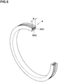
- a former having a ring shape with a circumferential groove (b) extending in the circumferential direction, as shown in Fig. 6 , for manufacturing a bead core (e) which is a component of a tire (not shown in the figures).
- the bead core (e) is formed by placing a bead wire (c) on a groove bottom face (h) of the circumferential groove (b) and helically winding the bead wire (c) on an outside thereof in a radial direction of the bead core.
- the present invention was made in view of the above, and a primary object thereof is to provide a bead core forming former capable of manufacturing bead cores having different widths by providing a width adjusting portion for changing the width of the circumferential groove.
- an annular bead core forming former for manufacturing a bead core including a wire array in which a bead wire is helically wound in a width direction of the bead core, comprises a main body portion having an outer circumferential surface with a circumferential groove extending in a circumferential direction for winding the bead wire and at least one width adjusting portion which moves relatively to the main body portion to changes a width of the circumferential groove.
- the circumferential groove has a groove bottom surface on which the bead wire is placed and at least one recessed portion extending inwardly in a radial direction of the bead core from the groove bottom surface, and the width adjusting portion has a protruding portion for positioning to be fitted with the at least one recessed portion.
- a plurality of the recessed portions is arranged in the width direction of the bead core.
- the at least one width adjusting portion is fixed to the main body portion with a screw member.
- a plurality of the width adjusting portions is provided at intervals in the circumferential direction.
- Fig. 1 is a perspective view of a bead core forming former (hereinafter may be simply referred to as "former") 1 in first embodiment.
- the former 1 is for manufacturing a bead core 20 (shown in Fig. 2 ) which is a component of a tire (not shown in the figures).
- the former 1 in this embodiment can manufacture the bead cores 20 used for various tires such as for passenger cars and motorcycles, for example.
- Fig. 2 is a cross-sectional view of the former 1 in this embodiment, taken orthogonal to a circumferential direction thereof, in which the bead core 20 is formed.
- the bead core 20 in this embodiment includes a wire array 22 formed with one or a plurality of parallel bead wires 21 helically wound by shifting in a width direction of the bead core 20 (hereinafter may be simply referred to as "width direction").
- the wire array 22 is stacked in multiple stages in a radial direction of the bead core 20 (hereinafter may be simply referred to as "radial direction").
- the width direction is indicated by x and the radial direction is indicated by Y.
- bead wire 21 is not particularly limited as long as it is non-stretchable, it is preferred that a steel wire coated with rubber is used as the bead wire 21, for example, from the point of view of securing rigidity and formability of a bead portion (not shown in the figures) of the tire.
- the former 1 in this embodiment is formed in an annular shape extending in the circumferential direction.
- the former 1 in this embodiment includes a main body portion 2 having a circumferential groove 4 concave from an outer circumferential surface 2a and extending in the circumferential direction for winding the bead wires 21 (shown in Fig. 2 ), and at least one width adjusting portion 3 for changing a width (w) of the circumferential groove 4 by moving relatively to the main body portion 2.
- the width (w) of the circumferential groove 4 means a width of a region around which the bead wires 21 are wound.
- the main body portion 2 is configured to include, for example, a plurality of segments 2A expandable and reducible in the radial direction. Thereby, after the bead wires 21 are wound, the bead core 20 can be easily removed from the circumferential groove 4 of the main body portion 2 by reducing a diameter of the segments 2A.
- a means for expanding and reducing the segments 2A one having a well-known structure (not shown in the figures) is used.
- the circumferential groove 4 in this embodiment has a groove bottom surface 5 on which the bead wires 21 are placed, a pair of inner side surfaces 6 connecting the groove bottom surface 5 and the outer circumferential surface 2a, and at least one recessed portion 7 extending radially inwardly from the groove bottom surface 5.
- the circumferential groove 4 in this embodiment is formed in a rectangular shape in a cross-sectional view orthogonal to the circumferential direction.
- the circumferential groove 4 is not limited to such a configuration, and for example, the circumferential groove 4 may have a trapezoidal shape (not shown in the figures) with the groove bottom surface 5 continuously inclined to the radial direction from one end 5e to the other end 5i in the width direction.
- the groove bottom surface 5 in this embodiment extends substantially continuously in the circumferential direction.
- substantially continuously includes, for example, a case in which a gap (not shown in the figures) or the like is provided between the segments 2A adjacent to each other in the circumferential direction in order to secure a length in the circumferential direction of the bead core 20.
- the main body portion 2 in this embodiment includes a concave portion 8 that is recessed from at least one of the inner side surfaces 6 (an inner side surface 6A on the right side in Fig. 2 ) in a direction away from the circumferential groove 4. Note that the other one of the inner side surfaces 6 in this embodiment (an inner side surface 6B) extends straight in the radial direction without having the concave portion 8 formed thereon.
- the concave portion 8 in this embodiment is formed in a rectangular shape in the cross-sectional view.
- the groove bottom surface 5 in this embodiment is provided with a plurality of the recessed portions 7 spaced from each other in the width direction. It is preferred that a pitch (p) of the recessed portions 7 in the width direction is set to be the same length as a diameter (d) of the bead wires 21.
- the at least one recessed portion 7 has a tapered surface 7a so that a width of the at least one recessed portion 7 increases toward the outside in the radial direction in the cross-sectional view orthogonal to the circumferential direction.
- a sectional shape of the at least one recessed portion 7 is not limited to such a shape, but may be, for example, a rectangular shape or a semicircular shape.
- the at least one width adjusting portion 3 in this embodiment includes a holding portion 10 for holding the bead wires 21 stacked in multiple stages within the circumferential groove 4, and a slide portion 11 connected to the holding portion 10 and having a height smaller than that of the holding portion 10 in the radial direction.
- the holding portion 10 in this embodiment is formed so as to have a substantially rectangular shape in the cross-sectional view including a radial direction surface 10a in contact with end surfaces 20A of the bead cores 20 in the width direction and extending in the radial direction, and a width direction surface 10b extending along the groove bottom surface 5.
- the radial direction surface 10a it is sufficient for the radial direction surface 10a to have a height enough to be at least in contact with the end surfaces 20A of the wire array 22a arranged outermost in the radial direction.
- the width direction surface 10b in this embodiment has an abutting surface 12 in contact with the groove bottom surface 5 and a protruding portion 13 to be fitted with any one of the recessed portions 7 in this embodiment.
- the protruding portion 13 has a tapered surface 13a so that a width of the protruding portion 13 decreases toward the inside of the radial direction. It is preferred that a length w1 of the width direction surface 10b in the width direction is not less than a diameter (d) of the bead wires 21.
- the length w1 in this embodiment is the same as the diameter (d) of the bead wires 21.
- the slide portion 11 in this embodiment is disposed in the concave portion 8.
- the slide portion 11 is fixed to the main body portion 2 by screw members 14.
- the screw members 14 are screwed into holes 15 provided in the outer circumferential surface 2a located outside the concave portion 8 in the radial direction, therefore, it is possible that the slide portion 11 is fixed to the concave portion 8 by pressure contact.
- the screw members 14 various kinds of screws, bolts and the like can be used.
- At least one screw member 14 is provided in each of the segments 2A, and it is preferred that not less than two screw members 14 are provided in each of the segments 2A in consideration of secure fixing of the at least one width adjusting portion 3.
- a plurality of the width adjusting portions 3 is provided at intervals in the circumferential direction in this embodiment.
- the width adjusting portions 3 in this embodiment are each provided in each of the segments 2A of the main body portion 2.
- the width adjusting portion 3 is not limited to such a configuration, and any number of the width adjusting portion 3 can be provided in each of the segments 2A as long as the bead wires 21 can be wound accurately.
- the bead cores 20 having different widths can be manufactured by moving the holding portion 10 in the width direction in the circumferential groove 4.
- the protruding portion 13 of the holding portion 10 and the at least one recessed portion 7 of the circumferential groove 4 are fitted to each other, it is possible that a position of the width adjusting portion 3 is determined accurately and easily. Furthermore, by providing a plurality of the recessed portions 7 in the width direction, the bead cores 20 having different widths can be manufactured accurately and easily. Further, the slide portion 11 is fixed by the screw member, therefore, it is possible that shape loss of the bead wires 21 while being wound is suppressed securely. Thereby, by using the former 1 in this embodiment, it is possible that the bead cores 20 with different widths are manufactured accurately and easily.
- Fig. 3A and Fig. 3B show a former 1a according to second embodiment.
- the same reference numbers are assigned to components having the same configuration as those of the former 1 of the first embodiment, and the description thereof is omitted.
- the at least one width adjusting portion 3 is formed by at least one screw member 16.
- the at least one width adjusting portion 3 includes a disk-shaped holding portion 17 disposed in the circumferential groove 4, and a threaded portion 18 connected to the holding portion 17 and screwed to the concave portion 8 of the main body portion 2.
- the holding portion 17 has the radial direction surface 10a extending in the radial direction and in contact with the end surfaces 20A of the bead cores 20 in the width direction.
- the width (w) of the circumferential groove 4 can be changed and fixed easily by rotating the holding portion 17 of the width adjusting portion 3 around its axis.
- the recessed portion 7 described above is omitted.
- the screw member 16 is not limited to such a configuration and may have a structure capable of moving all the holding portions 17 of the former 1a in the axial direction at once, for example.
- Fig. 4 shows a former 1b according to third embodiment.
- the at least one width adjusting portion 3 is formed by at least one screw member 16.
- the at least one width adjusting portion 3 has the disk-shaped holding portion 17 disposed in the circumferential groove 4, the threaded portion 18 connected to the holding portion 17 and screwed to the concave portion 8 of the main body portion 2, and a positioning portion 25 connected to the threaded portion 18 and located outside the main body portion 2.
- the positioning portion 25 provided outside the main body portion 2 around an axis of the threaded portion 18, the position of the holding portion 17 in the width direction is determined and fixed.
- Fig. 5 is a cross-sectional view of a former 1c according to fourth embodiment.
- the same reference numbers are assigned to components having the same configuration as those of the former 1 of the first embodiment, and the description thereof is omitted.
- the groove bottom surface 5 on which the bead wires 21 are placed is formed to have at least one small groove portion 19, preferably a plurality of them, having a substantially semicircular shape and a radius of curvature substantially equal to the radius of the bead wires 21. with the at least one small groove portion 19 configured as such, it is possible that the bead wires 21 are easily positioned.
- the protruding portion 13 of the holding portion 10 in this embodiment is formed in a semicircular arc shape convex toward the inside in the radial direction so as to fit into the at least one small groove portion 19. Thereby, it is possible that movement of the holding portion 10 in the width direction is effectively constrained.
Landscapes
- Engineering & Computer Science (AREA)
- Mechanical Engineering (AREA)
- Tyre Moulding (AREA)
- Tires In General (AREA)
Abstract
Description
- The present invention relates to a former for forming bead cores capable of manufacturing bead cores having different widths.
- There has been known a former (a) having a ring shape with a circumferential groove (b) extending in the circumferential direction, as shown in
Fig. 6 , for manufacturing a bead core (e) which is a component of a tire (not shown in the figures). The bead core (e) is formed by placing a bead wire (c) on a groove bottom face (h) of the circumferential groove (b) and helically winding the bead wire (c) on an outside thereof in a radial direction of the bead core. - Unfortunately, with the former (a) configured as such, only the bead cores having the same width as a width (k) of the circumferential groove (b) can be manufactured. Therefore, there has been a problem that a plurality of formers (a) having circumferential grooves (b) with different widths (k) is necessary in order to manufacture bead cores (e) having different widths.
- The present invention was made in view of the above, and a primary object thereof is to provide a bead core forming former capable of manufacturing bead cores having different widths by providing a width adjusting portion for changing the width of the circumferential groove.
- In one aspect of the present invention, an annular bead core forming former, for manufacturing a bead core including a wire array in which a bead wire is helically wound in a width direction of the bead core, comprises a main body portion having an outer circumferential surface with a circumferential groove extending in a circumferential direction for winding the bead wire and at least one width adjusting portion which moves relatively to the main body portion to changes a width of the circumferential groove.
- In another aspect of the invention, it is preferred that the circumferential groove has a groove bottom surface on which the bead wire is placed and at least one recessed portion extending inwardly in a radial direction of the bead core from the groove bottom surface, and the width adjusting portion has a protruding portion for positioning to be fitted with the at least one recessed portion.
- In another aspect of the invention, it is preferred that a plurality of the recessed portions is arranged in the width direction of the bead core.
- In another aspect of the invention, it is preferred that the at least one width adjusting portion is fixed to the main body portion with a screw member.
- In another aspect of the invention, it is preferred that a plurality of the width adjusting portions is provided at intervals in the circumferential direction.
-
-
Fig. 1 is a perspective view of the bead core forming former of first embodiment of the present invention. -
Fig. 2 is a cross-sectional view of the bead core forming former ofFig. 1 in a state where the bead wire is wound. -
Fig. 3A is a perspective view of the bead core forming former of second embodiment of the present invention. -
Fig. 3B is a cross-sectional view of the bead core forming former ofFig. 3A . -
Fig. 4 is a cross-sectional view of the bead core forming former of third embodiment of the present invention. -
Fig. 5 is a cross-sectional view of the bead core forming former of fourth embodiment of the present invention. -
Fig. 6 is a perspective view illustrating a conventional bead core forming former. - Embodiments of the present invention will now be described in conjunction with accompanying drawings.
-
Fig. 1 is a perspective view of a bead core forming former (hereinafter may be simply referred to as "former") 1 in first embodiment. The former 1 is for manufacturing a bead core 20 (shown inFig. 2 ) which is a component of a tire (not shown in the figures). The former 1 in this embodiment can manufacture thebead cores 20 used for various tires such as for passenger cars and motorcycles, for example. -
Fig. 2 is a cross-sectional view of the former 1 in this embodiment, taken orthogonal to a circumferential direction thereof, in which thebead core 20 is formed. As shown inFig. 2 , thebead core 20 in this embodiment includes awire array 22 formed with one or a plurality ofparallel bead wires 21 helically wound by shifting in a width direction of the bead core 20 (hereinafter may be simply referred to as "width direction"). In thebead core 20 in this embodiment, thewire array 22 is stacked in multiple stages in a radial direction of the bead core 20 (hereinafter may be simply referred to as "radial direction"). In each figure, the width direction is indicated by x and the radial direction is indicated by Y. - Although the
bead wire 21 is not particularly limited as long as it is non-stretchable, it is preferred that a steel wire coated with rubber is used as thebead wire 21, for example, from the point of view of securing rigidity and formability of a bead portion (not shown in the figures) of the tire. - As shown in
Fig. 1 , the former 1 in this embodiment is formed in an annular shape extending in the circumferential direction. The former 1 in this embodiment includes amain body portion 2 having acircumferential groove 4 concave from an outercircumferential surface 2a and extending in the circumferential direction for winding the bead wires 21 (shown inFig. 2 ), and at least onewidth adjusting portion 3 for changing a width (w) of thecircumferential groove 4 by moving relatively to themain body portion 2. In this specification, the width (w) of thecircumferential groove 4 means a width of a region around which thebead wires 21 are wound. - The
main body portion 2 is configured to include, for example, a plurality ofsegments 2A expandable and reducible in the radial direction. Thereby, after thebead wires 21 are wound, thebead core 20 can be easily removed from thecircumferential groove 4 of themain body portion 2 by reducing a diameter of thesegments 2A. As a means for expanding and reducing thesegments 2A, one having a well-known structure (not shown in the figures) is used. - As shown in
Fig. 2 , thecircumferential groove 4 in this embodiment has agroove bottom surface 5 on which thebead wires 21 are placed, a pair ofinner side surfaces 6 connecting thegroove bottom surface 5 and the outercircumferential surface 2a, and at least onerecessed portion 7 extending radially inwardly from thegroove bottom surface 5. - The
circumferential groove 4 in this embodiment is formed in a rectangular shape in a cross-sectional view orthogonal to the circumferential direction. Note that thecircumferential groove 4 is not limited to such a configuration, and for example, thecircumferential groove 4 may have a trapezoidal shape (not shown in the figures) with thegroove bottom surface 5 continuously inclined to the radial direction from oneend 5e to theother end 5i in the width direction. - The
groove bottom surface 5 in this embodiment extends substantially continuously in the circumferential direction. The terms "substantially continuously" includes, for example, a case in which a gap (not shown in the figures) or the like is provided between thesegments 2A adjacent to each other in the circumferential direction in order to secure a length in the circumferential direction of thebead core 20. - The
main body portion 2 in this embodiment includes aconcave portion 8 that is recessed from at least one of the inner side surfaces 6 (aninner side surface 6A on the right side inFig. 2 ) in a direction away from thecircumferential groove 4. Note that the other one of theinner side surfaces 6 in this embodiment (aninner side surface 6B) extends straight in the radial direction without having theconcave portion 8 formed thereon. - The
concave portion 8 in this embodiment is formed in a rectangular shape in the cross-sectional view. - The
groove bottom surface 5 in this embodiment is provided with a plurality of therecessed portions 7 spaced from each other in the width direction. It is preferred that a pitch (p) of therecessed portions 7 in the width direction is set to be the same length as a diameter (d) of thebead wires 21. - The at least one
recessed portion 7 has atapered surface 7a so that a width of the at least onerecessed portion 7 increases toward the outside in the radial direction in the cross-sectional view orthogonal to the circumferential direction. Note that a sectional shape of the at least onerecessed portion 7 is not limited to such a shape, but may be, for example, a rectangular shape or a semicircular shape. - The at least one
width adjusting portion 3 in this embodiment includes aholding portion 10 for holding thebead wires 21 stacked in multiple stages within thecircumferential groove 4, and aslide portion 11 connected to theholding portion 10 and having a height smaller than that of theholding portion 10 in the radial direction. - The
holding portion 10 in this embodiment is formed so as to have a substantially rectangular shape in the cross-sectional view including aradial direction surface 10a in contact withend surfaces 20A of thebead cores 20 in the width direction and extending in the radial direction, and awidth direction surface 10b extending along thegroove bottom surface 5. - It is sufficient for the
radial direction surface 10a to have a height enough to be at least in contact with theend surfaces 20A of thewire array 22a arranged outermost in the radial direction. - The
width direction surface 10b in this embodiment has anabutting surface 12 in contact with thegroove bottom surface 5 and a protrudingportion 13 to be fitted with any one of the recessedportions 7 in this embodiment. The protrudingportion 13 has atapered surface 13a so that a width of the protrudingportion 13 decreases toward the inside of the radial direction. It is preferred that a length w1 of thewidth direction surface 10b in the width direction is not less than a diameter (d) of thebead wires 21. The length w1 in this embodiment is the same as the diameter (d) of thebead wires 21. - The
slide portion 11 in this embodiment is disposed in theconcave portion 8. Theslide portion 11 is fixed to themain body portion 2 byscrew members 14. Specifically, thescrew members 14 are screwed intoholes 15 provided in the outercircumferential surface 2a located outside theconcave portion 8 in the radial direction, therefore, it is possible that theslide portion 11 is fixed to theconcave portion 8 by pressure contact. As thescrew members 14, various kinds of screws, bolts and the like can be used. At least onescrew member 14 is provided in each of thesegments 2A, and it is preferred that not less than twoscrew members 14 are provided in each of thesegments 2A in consideration of secure fixing of the at least onewidth adjusting portion 3. - As shown in
Fig. 1 , a plurality of thewidth adjusting portions 3 is provided at intervals in the circumferential direction in this embodiment. Thewidth adjusting portions 3 in this embodiment are each provided in each of thesegments 2A of themain body portion 2. Note that thewidth adjusting portion 3 is not limited to such a configuration, and any number of thewidth adjusting portion 3 can be provided in each of thesegments 2A as long as thebead wires 21 can be wound accurately. - with the former 1 configured as such, the
bead cores 20 having different widths can be manufactured by moving the holdingportion 10 in the width direction in thecircumferential groove 4. - Further, the protruding
portion 13 of the holdingportion 10 and the at least one recessedportion 7 of thecircumferential groove 4 are fitted to each other, it is possible that a position of thewidth adjusting portion 3 is determined accurately and easily. Furthermore, by providing a plurality of the recessedportions 7 in the width direction, thebead cores 20 having different widths can be manufactured accurately and easily. Further, theslide portion 11 is fixed by the screw member, therefore, it is possible that shape loss of thebead wires 21 while being wound is suppressed securely. Thereby, by using the former 1 in this embodiment, it is possible that thebead cores 20 with different widths are manufactured accurately and easily. -
Fig. 3A and Fig. 3B show a former 1a according to second embodiment. The same reference numbers are assigned to components having the same configuration as those of the former 1 of the first embodiment, and the description thereof is omitted. - In the former 1a in this embodiment, the at least one
width adjusting portion 3 is formed by at least onescrew member 16. Specifically, the at least onewidth adjusting portion 3 includes a disk-shaped holdingportion 17 disposed in thecircumferential groove 4, and a threadedportion 18 connected to the holdingportion 17 and screwed to theconcave portion 8 of themain body portion 2. The holdingportion 17 has theradial direction surface 10a extending in the radial direction and in contact with the end surfaces 20A of thebead cores 20 in the width direction. In the former 1a configured as such, the width (w) of thecircumferential groove 4 can be changed and fixed easily by rotating the holdingportion 17 of thewidth adjusting portion 3 around its axis. In the case of this embodiment, the recessedportion 7 described above is omitted. Note that thescrew member 16 is not limited to such a configuration and may have a structure capable of moving all the holdingportions 17 of the former 1a in the axial direction at once, for example. -
Fig. 4 shows a former 1b according to third embodiment. The same reference numbers are assigned to components having the same configuration as those of the former 1a of the second embodiment shown inFig. 3 , and the description thereof is omitted. In the former 1b in this embodiment, the at least onewidth adjusting portion 3 is formed by at least onescrew member 16. Specifically, the at least onewidth adjusting portion 3 has the disk-shaped holdingportion 17 disposed in thecircumferential groove 4, the threadedportion 18 connected to the holdingportion 17 and screwed to theconcave portion 8 of themain body portion 2, and apositioning portion 25 connected to the threadedportion 18 and located outside themain body portion 2. In the former 1b of this embodiment, by rotating thepositioning portion 25 provided outside themain body portion 2 around an axis of the threadedportion 18, the position of the holdingportion 17 in the width direction is determined and fixed. -
Fig. 5 is a cross-sectional view of a former 1c according to fourth embodiment. The same reference numbers are assigned to components having the same configuration as those of the former 1 of the first embodiment, and the description thereof is omitted. In thecircumferential groove 4 of the former 1c of this embodiment, thegroove bottom surface 5 on which thebead wires 21 are placed is formed to have at least onesmall groove portion 19, preferably a plurality of them, having a substantially semicircular shape and a radius of curvature substantially equal to the radius of thebead wires 21. with the at least onesmall groove portion 19 configured as such, it is possible that thebead wires 21 are easily positioned. - The protruding
portion 13 of the holdingportion 10 in this embodiment is formed in a semicircular arc shape convex toward the inside in the radial direction so as to fit into the at least onesmall groove portion 19. Thereby, it is possible that movement of the holdingportion 10 in the width direction is effectively constrained. - while detailed description has been made of especially preferred embodiments of the present invention, the present invention can be embodied in various forms without being limited to the illustrated embodiments.
Claims (5)
- An annular bead core forming former for manufacturing a bead core including a wire array in which a bead wire is helically wound in a width direction of the bead core, the bead core forming former comprising:a main body portion having an outer circumferential surface with a circumferential groove extending in a circumferential direction for winding the bead wire; andat least one width adjusting portion which moves relatively to the main body portion to changes a width of the circumferential groove.
- The bead core forming former according to claim 1, wherein,
the circumferential groove has a groove bottom surface on which the bead wire is placed and at least one recessed portion extending inwardly in a radial direction of the bead core from the groove bottom surface, and
the width adjusting portion has a protruding portion for positioning to be fitted with the at least one recessed portion. - The bead core forming former according to claim 2, wherein a plurality of the recessed portions is arranged in the width direction of the bead core.
- The bead core forming former according to any one of claims 1 to 3, wherein the at least one width adjusting portion is fixed to the main body portion with a screw member.
- The bead core forming former according to any one of claims 1 to 4, wherein a plurality of the width adjusting portions is provided at intervals in the circumferential direction.
Applications Claiming Priority (1)
| Application Number | Priority Date | Filing Date | Title |
|---|---|---|---|
| JP2016136140A JP6855694B2 (en) | 2016-07-08 | 2016-07-08 | Former for bead core formation |
Publications (2)
| Publication Number | Publication Date |
|---|---|
| EP3266600A1 true EP3266600A1 (en) | 2018-01-10 |
| EP3266600B1 EP3266600B1 (en) | 2019-10-02 |
Family
ID=59152680
Family Applications (1)
| Application Number | Title | Priority Date | Filing Date |
|---|---|---|---|
| EP17177280.9A Active EP3266600B1 (en) | 2016-07-08 | 2017-06-22 | Bead core forming former |
Country Status (4)
| Country | Link |
|---|---|
| US (1) | US10946603B2 (en) |
| EP (1) | EP3266600B1 (en) |
| JP (1) | JP6855694B2 (en) |
| CN (1) | CN107584787B (en) |
Families Citing this family (2)
| Publication number | Priority date | Publication date | Assignee | Title |
|---|---|---|---|---|
| CN108215262B (en) * | 2018-03-21 | 2020-06-16 | 山东胜通钢帘线有限公司 | Cable type bead winding machine |
| CN113199911A (en) * | 2021-05-24 | 2021-08-03 | 湖北奥莱斯轮胎股份有限公司 | Load radial tire with full contact steel wire ring and winding disc thereof |
Citations (5)
| Publication number | Priority date | Publication date | Assignee | Title |
|---|---|---|---|---|
| US5820717A (en) * | 1996-10-04 | 1998-10-13 | Bridgestone Corporation | Metal tire bead manufacturing method |
| US20080066851A1 (en) * | 2004-05-28 | 2008-03-20 | Bridgestone Corporation | Bead Member Forming Method and Apparatus |
| KR101425538B1 (en) * | 2012-09-27 | 2014-07-31 | 한국타이어 주식회사 | Former of bead for tire |
| US20150083270A1 (en) * | 2012-04-11 | 2015-03-26 | Fuji Seiko Co., Ltd. | Winder |
| US20150174841A1 (en) * | 2012-06-22 | 2015-06-25 | Kihachiro Nishida | Winding device |
Family Cites Families (7)
| Publication number | Priority date | Publication date | Assignee | Title |
|---|---|---|---|---|
| US3051221A (en) * | 1958-11-24 | 1962-08-28 | Nat Standard Co | Former for bead building machines or the like |
| JPH0857980A (en) * | 1994-08-26 | 1996-03-05 | Sumitomo Rubber Ind Ltd | Bead molding equipment |
| JPH09267410A (en) * | 1996-04-02 | 1997-10-14 | Tokyo Seiko Co Ltd | Bead forming machine and linear body winding device |
| JP2007160830A (en) * | 2005-12-16 | 2007-06-28 | Bridgestone Corp | Forming apparatus for polygonal bead core for pneumatic tire |
| JP2013078902A (en) * | 2011-10-04 | 2013-05-02 | Sumitomo Rubber Ind Ltd | Method of manufacturing bead core and method of manufacturing pneumatic tire |
| CN202830636U (en) * | 2012-10-25 | 2013-03-27 | 苏州联科合成材料有限公司 | Limiting device for coating machine |
| CN203536873U (en) * | 2013-10-11 | 2014-04-09 | 国家电网公司 | Handle-type cable stripper |
-
2016
- 2016-07-08 JP JP2016136140A patent/JP6855694B2/en active Active
-
2017
- 2017-06-02 CN CN201710407381.9A patent/CN107584787B/en active Active
- 2017-06-16 US US15/625,121 patent/US10946603B2/en active Active
- 2017-06-22 EP EP17177280.9A patent/EP3266600B1/en active Active
Patent Citations (5)
| Publication number | Priority date | Publication date | Assignee | Title |
|---|---|---|---|---|
| US5820717A (en) * | 1996-10-04 | 1998-10-13 | Bridgestone Corporation | Metal tire bead manufacturing method |
| US20080066851A1 (en) * | 2004-05-28 | 2008-03-20 | Bridgestone Corporation | Bead Member Forming Method and Apparatus |
| US20150083270A1 (en) * | 2012-04-11 | 2015-03-26 | Fuji Seiko Co., Ltd. | Winder |
| US20150174841A1 (en) * | 2012-06-22 | 2015-06-25 | Kihachiro Nishida | Winding device |
| KR101425538B1 (en) * | 2012-09-27 | 2014-07-31 | 한국타이어 주식회사 | Former of bead for tire |
Also Published As
| Publication number | Publication date |
|---|---|
| JP6855694B2 (en) | 2021-04-07 |
| JP2018001733A (en) | 2018-01-11 |
| US10946603B2 (en) | 2021-03-16 |
| CN107584787A (en) | 2018-01-16 |
| US20180009185A1 (en) | 2018-01-11 |
| EP3266600B1 (en) | 2019-10-02 |
| CN107584787B (en) | 2021-03-19 |
Similar Documents
| Publication | Publication Date | Title |
|---|---|---|
| US9253576B2 (en) | Suspension for acoustic device | |
| US10505408B2 (en) | Stator, stator manufacturing method and motor | |
| ES2865277T3 (en) | Bearing with shoulder segments | |
| JP6267315B2 (en) | Bearing assembly for steering column | |
| EP3266600B1 (en) | Bead core forming former | |
| EP2860022A1 (en) | Tire shaping drum | |
| US20190068009A1 (en) | Stator, stator manufacturing method and motor | |
| US11316414B2 (en) | Method of manufacturing coil and method of manufacturing motor | |
| US20200191223A1 (en) | Spring package with stamped and bent supporting ring | |
| EP3789210A1 (en) | Non-pneumatic tire | |
| KR20120073624A (en) | Sleeve for mandrel advanced durable | |
| JP6801285B2 (en) | Bead core manufacturing equipment | |
| EP3378636B1 (en) | Belt drum | |
| US20190190357A1 (en) | Stator, stator manufacturing method and motor | |
| KR101605525B1 (en) | Roll brush of vehicle wheel polishing apparatus | |
| JP2005163939A (en) | Radial foil bearing | |
| JP2013078902A (en) | Method of manufacturing bead core and method of manufacturing pneumatic tire | |
| JP2009196191A (en) | Method and mechanism of locking bead core | |
| US20190207433A1 (en) | Contactless power supply coil unit | |
| WO2018062117A1 (en) | Contactless power feeding coil unit | |
| US20190190356A1 (en) | Stator, stator manufacturing method and motor | |
| JP2009190552A (en) | Bead core | |
| WO2018199232A1 (en) | Spherical sliding bearing and method for manufacturing same | |
| CN116583415A (en) | Steel wire core of bead ring assembly in pneumatic tire for vehicle and manufacturing equipment thereof | |
| JP7189752B2 (en) | Bead transfer device |
Legal Events
| Date | Code | Title | Description |
|---|---|---|---|
| PUAI | Public reference made under article 153(3) epc to a published international application that has entered the european phase |
Free format text: ORIGINAL CODE: 0009012 |
|
| STAA | Information on the status of an ep patent application or granted ep patent |
Free format text: STATUS: THE APPLICATION HAS BEEN PUBLISHED |
|
| AK | Designated contracting states |
Kind code of ref document: A1 Designated state(s): AL AT BE BG CH CY CZ DE DK EE ES FI FR GB GR HR HU IE IS IT LI LT LU LV MC MK MT NL NO PL PT RO RS SE SI SK SM TR |
|
| AX | Request for extension of the european patent |
Extension state: BA ME |
|
| STAA | Information on the status of an ep patent application or granted ep patent |
Free format text: STATUS: REQUEST FOR EXAMINATION WAS MADE |
|
| 17P | Request for examination filed |
Effective date: 20180628 |
|
| RBV | Designated contracting states (corrected) |
Designated state(s): AL AT BE BG CH CY CZ DE DK EE ES FI FR GB GR HR HU IE IS IT LI LT LU LV MC MK MT NL NO PL PT RO RS SE SI SK SM TR |
|
| GRAP | Despatch of communication of intention to grant a patent |
Free format text: ORIGINAL CODE: EPIDOSNIGR1 |
|
| STAA | Information on the status of an ep patent application or granted ep patent |
Free format text: STATUS: GRANT OF PATENT IS INTENDED |
|
| RIC1 | Information provided on ipc code assigned before grant |
Ipc: B29D 30/48 20060101AFI20190404BHEP Ipc: D07B 7/02 20060101ALN20190404BHEP Ipc: D07B 7/16 20060101ALI20190404BHEP |
|
| INTG | Intention to grant announced |
Effective date: 20190418 |
|
| GRAS | Grant fee paid |
Free format text: ORIGINAL CODE: EPIDOSNIGR3 |
|
| GRAA | (expected) grant |
Free format text: ORIGINAL CODE: 0009210 |
|
| STAA | Information on the status of an ep patent application or granted ep patent |
Free format text: STATUS: THE PATENT HAS BEEN GRANTED |
|
| AK | Designated contracting states |
Kind code of ref document: B1 Designated state(s): AL AT BE BG CH CY CZ DE DK EE ES FI FR GB GR HR HU IE IS IT LI LT LU LV MC MK MT NL NO PL PT RO RS SE SI SK SM TR |
|
| REG | Reference to a national code |
Ref country code: GB Ref legal event code: FG4D |
|
| REG | Reference to a national code |
Ref country code: CH Ref legal event code: EP Ref country code: AT Ref legal event code: REF Ref document number: 1185719 Country of ref document: AT Kind code of ref document: T Effective date: 20191015 |
|
| REG | Reference to a national code |
Ref country code: DE Ref legal event code: R096 Ref document number: 602017007399 Country of ref document: DE |
|
| REG | Reference to a national code |
Ref country code: IE Ref legal event code: FG4D |
|
| REG | Reference to a national code |
Ref country code: NL Ref legal event code: MP Effective date: 20191002 |
|
| REG | Reference to a national code |
Ref country code: LT Ref legal event code: MG4D |
|
| REG | Reference to a national code |
Ref country code: AT Ref legal event code: MK05 Ref document number: 1185719 Country of ref document: AT Kind code of ref document: T Effective date: 20191002 |
|
| PG25 | Lapsed in a contracting state [announced via postgrant information from national office to epo] |
Ref country code: NO Free format text: LAPSE BECAUSE OF FAILURE TO SUBMIT A TRANSLATION OF THE DESCRIPTION OR TO PAY THE FEE WITHIN THE PRESCRIBED TIME-LIMIT Effective date: 20200102 Ref country code: GR Free format text: LAPSE BECAUSE OF FAILURE TO SUBMIT A TRANSLATION OF THE DESCRIPTION OR TO PAY THE FEE WITHIN THE PRESCRIBED TIME-LIMIT Effective date: 20200103 Ref country code: PL Free format text: LAPSE BECAUSE OF FAILURE TO SUBMIT A TRANSLATION OF THE DESCRIPTION OR TO PAY THE FEE WITHIN THE PRESCRIBED TIME-LIMIT Effective date: 20191002 Ref country code: AT Free format text: LAPSE BECAUSE OF FAILURE TO SUBMIT A TRANSLATION OF THE DESCRIPTION OR TO PAY THE FEE WITHIN THE PRESCRIBED TIME-LIMIT Effective date: 20191002 Ref country code: SE Free format text: LAPSE BECAUSE OF FAILURE TO SUBMIT A TRANSLATION OF THE DESCRIPTION OR TO PAY THE FEE WITHIN THE PRESCRIBED TIME-LIMIT Effective date: 20191002 Ref country code: LV Free format text: LAPSE BECAUSE OF FAILURE TO SUBMIT A TRANSLATION OF THE DESCRIPTION OR TO PAY THE FEE WITHIN THE PRESCRIBED TIME-LIMIT Effective date: 20191002 Ref country code: BG Free format text: LAPSE BECAUSE OF FAILURE TO SUBMIT A TRANSLATION OF THE DESCRIPTION OR TO PAY THE FEE WITHIN THE PRESCRIBED TIME-LIMIT Effective date: 20200102 Ref country code: FI Free format text: LAPSE BECAUSE OF FAILURE TO SUBMIT A TRANSLATION OF THE DESCRIPTION OR TO PAY THE FEE WITHIN THE PRESCRIBED TIME-LIMIT Effective date: 20191002 Ref country code: PT Free format text: LAPSE BECAUSE OF FAILURE TO SUBMIT A TRANSLATION OF THE DESCRIPTION OR TO PAY THE FEE WITHIN THE PRESCRIBED TIME-LIMIT Effective date: 20200203 Ref country code: NL Free format text: LAPSE BECAUSE OF FAILURE TO SUBMIT A TRANSLATION OF THE DESCRIPTION OR TO PAY THE FEE WITHIN THE PRESCRIBED TIME-LIMIT Effective date: 20191002 Ref country code: ES Free format text: LAPSE BECAUSE OF FAILURE TO SUBMIT A TRANSLATION OF THE DESCRIPTION OR TO PAY THE FEE WITHIN THE PRESCRIBED TIME-LIMIT Effective date: 20191002 Ref country code: LT Free format text: LAPSE BECAUSE OF FAILURE TO SUBMIT A TRANSLATION OF THE DESCRIPTION OR TO PAY THE FEE WITHIN THE PRESCRIBED TIME-LIMIT Effective date: 20191002 |
|
| PG25 | Lapsed in a contracting state [announced via postgrant information from national office to epo] |
Ref country code: CZ Free format text: LAPSE BECAUSE OF FAILURE TO SUBMIT A TRANSLATION OF THE DESCRIPTION OR TO PAY THE FEE WITHIN THE PRESCRIBED TIME-LIMIT Effective date: 20191002 Ref country code: IS Free format text: LAPSE BECAUSE OF FAILURE TO SUBMIT A TRANSLATION OF THE DESCRIPTION OR TO PAY THE FEE WITHIN THE PRESCRIBED TIME-LIMIT Effective date: 20200224 Ref country code: HR Free format text: LAPSE BECAUSE OF FAILURE TO SUBMIT A TRANSLATION OF THE DESCRIPTION OR TO PAY THE FEE WITHIN THE PRESCRIBED TIME-LIMIT Effective date: 20191002 Ref country code: RS Free format text: LAPSE BECAUSE OF FAILURE TO SUBMIT A TRANSLATION OF THE DESCRIPTION OR TO PAY THE FEE WITHIN THE PRESCRIBED TIME-LIMIT Effective date: 20191002 |
|
| PG25 | Lapsed in a contracting state [announced via postgrant information from national office to epo] |
Ref country code: AL Free format text: LAPSE BECAUSE OF FAILURE TO SUBMIT A TRANSLATION OF THE DESCRIPTION OR TO PAY THE FEE WITHIN THE PRESCRIBED TIME-LIMIT Effective date: 20191002 |
|
| REG | Reference to a national code |
Ref country code: DE Ref legal event code: R097 Ref document number: 602017007399 Country of ref document: DE |
|
| PG2D | Information on lapse in contracting state deleted |
Ref country code: IS |
|
| PG25 | Lapsed in a contracting state [announced via postgrant information from national office to epo] |
Ref country code: RO Free format text: LAPSE BECAUSE OF FAILURE TO SUBMIT A TRANSLATION OF THE DESCRIPTION OR TO PAY THE FEE WITHIN THE PRESCRIBED TIME-LIMIT Effective date: 20191002 Ref country code: EE Free format text: LAPSE BECAUSE OF FAILURE TO SUBMIT A TRANSLATION OF THE DESCRIPTION OR TO PAY THE FEE WITHIN THE PRESCRIBED TIME-LIMIT Effective date: 20191002 Ref country code: DK Free format text: LAPSE BECAUSE OF FAILURE TO SUBMIT A TRANSLATION OF THE DESCRIPTION OR TO PAY THE FEE WITHIN THE PRESCRIBED TIME-LIMIT Effective date: 20191002 Ref country code: IS Free format text: LAPSE BECAUSE OF FAILURE TO SUBMIT A TRANSLATION OF THE DESCRIPTION OR TO PAY THE FEE WITHIN THE PRESCRIBED TIME-LIMIT Effective date: 20200202 |
|
| PLBE | No opposition filed within time limit |
Free format text: ORIGINAL CODE: 0009261 |
|
| STAA | Information on the status of an ep patent application or granted ep patent |
Free format text: STATUS: NO OPPOSITION FILED WITHIN TIME LIMIT |
|
| PG25 | Lapsed in a contracting state [announced via postgrant information from national office to epo] |
Ref country code: IT Free format text: LAPSE BECAUSE OF FAILURE TO SUBMIT A TRANSLATION OF THE DESCRIPTION OR TO PAY THE FEE WITHIN THE PRESCRIBED TIME-LIMIT Effective date: 20191002 Ref country code: SM Free format text: LAPSE BECAUSE OF FAILURE TO SUBMIT A TRANSLATION OF THE DESCRIPTION OR TO PAY THE FEE WITHIN THE PRESCRIBED TIME-LIMIT Effective date: 20191002 Ref country code: SK Free format text: LAPSE BECAUSE OF FAILURE TO SUBMIT A TRANSLATION OF THE DESCRIPTION OR TO PAY THE FEE WITHIN THE PRESCRIBED TIME-LIMIT Effective date: 20191002 |
|
| 26N | No opposition filed |
Effective date: 20200703 |
|
| PG25 | Lapsed in a contracting state [announced via postgrant information from national office to epo] |
Ref country code: SI Free format text: LAPSE BECAUSE OF FAILURE TO SUBMIT A TRANSLATION OF THE DESCRIPTION OR TO PAY THE FEE WITHIN THE PRESCRIBED TIME-LIMIT Effective date: 20191002 |
|
| PG25 | Lapsed in a contracting state [announced via postgrant information from national office to epo] |
Ref country code: MC Free format text: LAPSE BECAUSE OF FAILURE TO SUBMIT A TRANSLATION OF THE DESCRIPTION OR TO PAY THE FEE WITHIN THE PRESCRIBED TIME-LIMIT Effective date: 20191002 |
|
| REG | Reference to a national code |
Ref country code: CH Ref legal event code: PL |
|
| PG25 | Lapsed in a contracting state [announced via postgrant information from national office to epo] |
Ref country code: LU Free format text: LAPSE BECAUSE OF NON-PAYMENT OF DUE FEES Effective date: 20200622 |
|
| REG | Reference to a national code |
Ref country code: BE Ref legal event code: MM Effective date: 20200630 |
|
| PG25 | Lapsed in a contracting state [announced via postgrant information from national office to epo] |
Ref country code: CH Free format text: LAPSE BECAUSE OF NON-PAYMENT OF DUE FEES Effective date: 20200630 Ref country code: LI Free format text: LAPSE BECAUSE OF NON-PAYMENT OF DUE FEES Effective date: 20200630 Ref country code: IE Free format text: LAPSE BECAUSE OF NON-PAYMENT OF DUE FEES Effective date: 20200622 |
|
| PG25 | Lapsed in a contracting state [announced via postgrant information from national office to epo] |
Ref country code: BE Free format text: LAPSE BECAUSE OF NON-PAYMENT OF DUE FEES Effective date: 20200630 |
|
| GBPC | Gb: european patent ceased through non-payment of renewal fee |
Effective date: 20210622 |
|
| PG25 | Lapsed in a contracting state [announced via postgrant information from national office to epo] |
Ref country code: GB Free format text: LAPSE BECAUSE OF NON-PAYMENT OF DUE FEES Effective date: 20210622 |
|
| PG25 | Lapsed in a contracting state [announced via postgrant information from national office to epo] |
Ref country code: TR Free format text: LAPSE BECAUSE OF FAILURE TO SUBMIT A TRANSLATION OF THE DESCRIPTION OR TO PAY THE FEE WITHIN THE PRESCRIBED TIME-LIMIT Effective date: 20191002 Ref country code: MT Free format text: LAPSE BECAUSE OF FAILURE TO SUBMIT A TRANSLATION OF THE DESCRIPTION OR TO PAY THE FEE WITHIN THE PRESCRIBED TIME-LIMIT Effective date: 20191002 Ref country code: CY Free format text: LAPSE BECAUSE OF FAILURE TO SUBMIT A TRANSLATION OF THE DESCRIPTION OR TO PAY THE FEE WITHIN THE PRESCRIBED TIME-LIMIT Effective date: 20191002 |
|
| PG25 | Lapsed in a contracting state [announced via postgrant information from national office to epo] |
Ref country code: MK Free format text: LAPSE BECAUSE OF FAILURE TO SUBMIT A TRANSLATION OF THE DESCRIPTION OR TO PAY THE FEE WITHIN THE PRESCRIBED TIME-LIMIT Effective date: 20191002 |
|
| P01 | Opt-out of the competence of the unified patent court (upc) registered |
Free format text: CASE NUMBER: UPC_APP_110617/2023 Effective date: 20230510 |
|
| PGFP | Annual fee paid to national office [announced via postgrant information from national office to epo] |
Ref country code: DE Payment date: 20250429 Year of fee payment: 9 |
|
| PGFP | Annual fee paid to national office [announced via postgrant information from national office to epo] |
Ref country code: FR Payment date: 20250508 Year of fee payment: 9 |