EP3266573A1 - Enrouleur de gant ou de sac destine a equiper une boite a gant d'enceinte fermee - Google Patents
Enrouleur de gant ou de sac destine a equiper une boite a gant d'enceinte fermee Download PDFInfo
- Publication number
- EP3266573A1 EP3266573A1 EP17178802.9A EP17178802A EP3266573A1 EP 3266573 A1 EP3266573 A1 EP 3266573A1 EP 17178802 A EP17178802 A EP 17178802A EP 3266573 A1 EP3266573 A1 EP 3266573A1
- Authority
- EP
- European Patent Office
- Prior art keywords
- glove
- roller
- round
- bag
- axis
- Prior art date
- Legal status (The legal status is an assumption and is not a legal conclusion. Google has not performed a legal analysis and makes no representation as to the accuracy of the status listed.)
- Granted
Links
Images


Classifications
-
- B—PERFORMING OPERATIONS; TRANSPORTING
- B25—HAND TOOLS; PORTABLE POWER-DRIVEN TOOLS; MANIPULATORS
- B25J—MANIPULATORS; CHAMBERS PROVIDED WITH MANIPULATION DEVICES
- B25J21/00—Chambers provided with manipulation devices
- B25J21/02—Glove-boxes, i.e. chambers in which manipulations are performed by the human hands in gloves built into the chamber walls; Gloves therefor
-
- G—PHYSICS
- G21—NUCLEAR PHYSICS; NUCLEAR ENGINEERING
- G21F—PROTECTION AGAINST X-RADIATION, GAMMA RADIATION, CORPUSCULAR RADIATION OR PARTICLE BOMBARDMENT; TREATING RADIOACTIVELY CONTAMINATED MATERIAL; DECONTAMINATION ARRANGEMENTS THEREFOR
- G21F7/00—Shielded cells or rooms
- G21F7/04—Shielded glove-boxes
-
- G—PHYSICS
- G21—NUCLEAR PHYSICS; NUCLEAR ENGINEERING
- G21F—PROTECTION AGAINST X-RADIATION, GAMMA RADIATION, CORPUSCULAR RADIATION OR PARTICLE BOMBARDMENT; TREATING RADIOACTIVELY CONTAMINATED MATERIAL; DECONTAMINATION ARRANGEMENTS THEREFOR
- G21F7/00—Shielded cells or rooms
- G21F7/04—Shielded glove-boxes
- G21F7/047—Shielded passages; Closing or transferring means between glove-boxes
-
- G—PHYSICS
- G21—NUCLEAR PHYSICS; NUCLEAR ENGINEERING
- G21F—PROTECTION AGAINST X-RADIATION, GAMMA RADIATION, CORPUSCULAR RADIATION OR PARTICLE BOMBARDMENT; TREATING RADIOACTIVELY CONTAMINATED MATERIAL; DECONTAMINATION ARRANGEMENTS THEREFOR
- G21F7/00—Shielded cells or rooms
- G21F7/04—Shielded glove-boxes
- G21F7/053—Glove mounting means
Definitions
- the invention relates to rounds of gloves equipping a chamber of the glove box used in particular for the handling of radioactive material.
- a box comprises a body carrying transparent panels provided with openings receiving rounds of gloves to which gloves are attached. It is a closed chamber that is depressurized, and allows an operator to manipulate, through the gloves, the elements present in the box while being located outside this box.
- such a round of glove 1 comprises a body of revolution 2 engaged in a corresponding hole formed in a panel 3 of the box while being attached to this hole, and which has a central opening.
- the body of revolution 2 is a kind of socket having an inner portion located in the enclosure defined by the box, and an outer portion which protrudes from the panel 3 to extend out of the box.
- a glove 4 of elastomeric material or the like is fixed by its base to the external portion of the body 2, and it passes through this round of glove to extend mainly in the chamber in which it is naturally sucked because it is in depression.
- the round of glove 1 comprises a shutter 6 to close its central opening.
- the operator grasps with the glove the shutter left in the box and puts it in place in the central opening to close it tightly.
- the glove is located entirely out of the box and hangs vertically from its base attached to the outer portion of the glove ring.
- the operator puts his hand into the end of the glove, removes the shutter to deposit it in the box by engaging the glove through the opening so as to be able to perform its operations.
- such a round of glove can carry a vinyl bag 7 instead of a glove, as shown in figures 5 and 6 this bag being then used in a similar manner to extract one or more elements from the box.
- the element is then placed in the bag out of the box, before cutting and crimping the bag to be able to dispose of the element in question, without having put in communication the inside of the box with its environment.
- the subject of the invention is a reel comprising a roller and means for fastening to an outer portion of a round of glove equipping a closed vacuum enclosure or a panel carrying this round of glove, for winding out of this enclosure a glove or a bag carried by this round of glove.
- the invention thus makes it possible to wind a glove or a bag protruding out of the glove ring which carries it and to fix the retractor to this round of glove for the entire period during which the bag or the glove is unused.
- the invention also relates to a reel thus defined, comprising a roller carried by an axis and wherein the fixing means are formed by two fixing lugs by clasping the outer portion of the round of glove, each leg being traversed by one end of the axis and pressed against one end of the roller by a nut screwed at the end of the axis.
- the invention also relates to a reel thus defined, wherein one of the tabs is rigidly secured to one end of the axis.
- the invention also relates to a winder thus defined, wherein one of the nuts is a wing nut.
- the invention also relates to a reel thus defined, wherein the rotating roller comprises a locking slot for receiving an end of a glove or a bag before winding.
- the invention also relates to a reel thus defined, comprising a folding arm along the roller to grip against this roller an end of a glove or a bag to block it before winding.
- the invention also relates to a winder thus defined, wherein the fastening means are provided with snatch roller receiving members.
- the invention also relates to a winder thus defined, wherein the fixing means are arranged to be permanently fixed to the glove ring or to a panel carrying this round of glove.
- the invention also relates to a round of glove equipped with a winder thus defined.
- the idea underlying the invention is to avoid the suction of a bag or a glove under the effect of depression when the bag or glove is unused while the round of gloves to which it is fixed is without shutter.
- the round of glove 8 of the figure 6 comprises a body 9 having a shape of revolution corresponding to that of a sleeve delimiting a circular central opening 11.
- This body 9 comprises an inner portion 13 and an outer portion 12 provided with a plurality of outer circumferential grooves 14, this body 9 being engaged in a circular opening of a panel not shown.
- the body 9 is held on the panel by a ring 16 which surrounds its outer portion 12 to grip this panel between this ring 16 and the inner portion 13 of the body 9.
- the retractor according to the invention which is marked by 17 on the figure 6 comprises an axis 18 carrying a roller 19 extending over the majority of the length of this axis 18, as well as two fixing lugs 21, 22 each fixed at one end of this axis 18.
- the tab 21 has a general shape corresponding to that of a folded plate generally at right angles. It has a pierced end 23 through which it is fixed to a first end 24 of the assembly formed by the axis 18 carrying the roller 19, and a clamping end 26 bears against a groove 14 of the outer portion of the body 9 when the retractor is installed.
- the pierced end 23 of the lug 21 is clamped between a nut 27 screwed to a first end 28 of the shaft 18 and a first end 29 of the roller 19.
- the axis 18 and the roller 19 extend in a direction AX and the pierced end 23 extends in a plane normal to this direction AX when the winder is tightened.
- the clamping end 26 extends in parallel with the axis AX, that is to say perpendicular to the pierced end 23.
- This clamping end 26 ends with two keys, one of which is visible on the figure 6 where it is marked by 31, which are spaced from one another, and separated by a recess 32 allowing them to be one and the other resting in one of the grooves 14 when the reel is mounted.
- the second tab 22 is identical to the first tab 21, it also has a pierced end, marked by 33, and a clamping end, marked by 34 and extending at right angles to the pierced end 33.
- the second tab 22 is fixed to the second end 36 of the assembly formed by the roller 19 and its axis 18 being traversed by the opposite end of the axis 18, being pressed against the second end of the roller 19 by a wing nut 37 screwed to the second end of the shaft 18.
- the clamping ends 26 and 34 of the two tabs 21 and 22 jointly form the jaws of a clamp or a clamping clamping on the groove around the outer portion 12. Their clamping and loosening is obtained by manually tightening or loosening the wing nut 37.
- each tab is formed of two elements which are secured to one another, one corresponding to the clamping end, and the other corresponding to the pierced end, but each tab can also be formed of a single sheet metal cut, stamped and / or folded.
- lugs 21 and 22 may also be provided to carry additional equipment such as biological radiation protection means and / or a protective cover of the bag wound vis-à-vis mechanical aggression.
- the faces of the ends of the roller 19 extend parallel to each other perpendicularly to the axis of the roller 19. Tightening the wing nut 37 thus allows to simultaneously press the pierced ends 23 and 33 of the legs 21 and 22 respectively against the two ends of the roller 19 to bring the clamping ends 26, 34 of these tabs towards each other, and also to rotate the roller lock 19. Loosen the wing nut 37 allows a similar way to loosen these legs.
- the pierced end 23 comprises a thread
- the nut 27 is of the self-locking type, so that the first leg 21 is rigidly secured to the first end 28 of the axis 18, to simplify the handling of the winder. by an operator.
- the operator thus winds the bag 38 to the vicinity of its base which is fixed to the body 9 of the round of glove 8, which corresponds to the situation of the figure 9 in which the roller 19 is situated almost against the outer portion 12 of the body 9 of the round of glove 8.
- the operator engages the first lug 21 around the axis 18, bearing on the self-locking nut 27, and engages the rest of the axis 18 in the roller 19, and then engage around the second end of this axis 18 which protrudes from the second end of the roller 19, the second leg 22, and the wing nut 37.
- the roller 19 has a longitudinal slot in which the end of the bag or glove engages to block it.
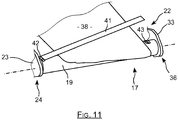
- the roller 19 carries a folding arm 41 which allows to grip the end of the glove or bag 38 against the roller to block it.
- this arm 41 has a generally rectilinear shape of a length substantially less than that of the roller 19.
- One end of this arm 41 is secured to one end 24 of the roller 19 by a hinge 42 of axis normal to the roll axis, and a fastener 43 is provided at the opposite end of this arm 41, to fix the arm 41 pressed against the roller 19 and along it so that it encloses the end of the bag 38.
- the winder according to the invention comprises a roller which is secured to the fixing lugs before fixing the assembly to the glove ring.
- the fixing paste can also be fixed permanently to the glove ring, or to the panel carrying this round of glove, on either side of it, for example by gluing.
- the roll is removable relative to the legs, and the user wraps the glove or the bag around the roll, before positioning the roll between the tabs to fix them for example by snapping to ensure its maintenance .
- the invention makes it possible to wind up an unused bag or glove to prevent it from being sucked into the enclosure, or to hang out of the enclosure when the round of glove to which it is fixed includes a shutter.
- the invention is easily adapted to different diameters of rounds of gloves, these being usually between one hundred and fifty-five hundred millimeters, and it has the advantage of adapting to the models of round gloves standardized.
- the invention applies to different types of vacuum chambers, which are generally used in the nuclear, chemical and also biological, and also hospitable.
Landscapes
- Engineering & Computer Science (AREA)
- Physics & Mathematics (AREA)
- General Engineering & Computer Science (AREA)
- High Energy & Nuclear Physics (AREA)
- Mechanical Engineering (AREA)
- Robotics (AREA)
- Gloves (AREA)
- Textile Engineering (AREA)
Abstract
Description
- L'invention se rapporte à des ronds de gants équipant une enceinte de type boîte à gants utilisée notamment pour la manipulation de matière radioactive. Une telle boîte comprend un corps portant des panneaux transparents pourvus d'ouvertures recevant des ronds de gants auxquels sont fixés des gants. Elle constitue une enceinte fermée qui est dépressurisée, et qui permet à un opérateur de manipuler, grâce aux gants, des éléments présents dans la boîte tout en étant situé hors de cette boîte.
- Comme représenté sur les
figures 1 et 2 , un tel rond de gant 1 comprend un corps de révolution 2 engagé dans un trou correspondant formé dans un panneau 3 de la boîte tout en étant fixé à ce trou, et qui comporte une ouverture centrale. - Le corps de révolution 2 constitue une sorte de douille présentant une portion interne située dans l'enceinte que délimite la boîte, et une portion externe qui dépasse du panneau 3 pour s'étendre hors de la boîte.
- Comme représenté sur la
figure 3 , un gant 4 en matière élastomère ou analogue est fixé par sa base à la portion externe du corps 2, et il traverse ce rond de gant pour s'étendre majoritairement dans l'enceinte dans laquelle il est naturellement aspiré du fait que celle-ci est en dépression. - En pratique, le rond de gant 1 comporte un obturateur 6 permettant de fermer son ouverture centrale. Lorsque l'opérateur a terminé sa manipulation, il saisit avec le gant l'obturateur laissé dans la boîte et le met en place dans l'ouverture centrale pour la fermer hermétiquement. A ce stade, le gant est situé entièrement hors de la boîte et pend verticalement depuis sa base fixée à la portion externe du rond de gant. Pour réaliser une nouvelle manipulation, l'opérateur enfile sa main dans l'extrémité du gant, retire l'obturateur pour le déposer dans la boîte en engageant le gant à travers l'ouverture de façon à être en mesure de réaliser ses opérations.
- Lorsque le rond de gant est dépourvu d'obturateur, l'opérateur sort les gants qu'il utilise et il les noue l'un à l'autre hors de la boîte pour éviter qu'ils ne soient aspirés par la dépression régnant dans cette boîte.
- D'une manière analogue, un tel rond de gant peut porter un sac 7 en vinyle au lieu d'un gant, comme représenté sur les
figures 5 et6 , ce sac étant alors utilisé d'une manière analogue pour extraire de la boîte un ou des éléments qu'elle contient. Comme visible sur lafigure 4 , l'élément est alors placé dans le sac hors de la boîte, avant de couper et sertir ce sac pour pouvoir disposer de l'élément en question, sans avoir mis en communication l'intérieur de la boîte avec son environnement. - Lorsque le rond de gant est équipé d'un sac en vinyle 7, il n'est généralement pas possible de nouer ce sac à l'extérieur, de sorte qu'il reste alors en étant aspiré vers l'intérieur comme illustré sur la
figure 5 . Ceci induit notamment que le sac est continuellement sollicité en tension, ce qui accélère sa dégradation, impliquant par là-même son remplacement anticipé et la production d'un déchet non souhaitée. - A cet effet, l'invention a pour objet un enrouleur comprenant un rouleau et des moyens de fixation à une portion externe d'un rond de gant équipant une enceinte fermée à dépression ou à un panneau portant ce rond de gant, pour enrouler hors de cette enceinte un gant ou un sac porté par ce rond de gant.
- L'invention permet ainsi d'enrouler un gant ou un sac dépassant hors du rond de gant qui le porte et de fixer l'enrouleur à ce rond de gant pour toute la période durant laquelle le sac ou le gant est inutilisé.
- L'invention concerne également un enrouleur ainsi défini, comprenant un rouleau porté par un axe et dans lequel les moyens de fixation sont formés par deux pattes de fixation par enserrement de la portion externe du rond de gant, chaque patte étant traversée par une extrémité de l'axe et pressée contre une extrémité du rouleau par un écrou vissé en extrémité d'axe.
- L'invention concerne également un enrouleur ainsi défini, dans lequel l'une des pattes est rigidement solidarisée à une extrémité de l'axe.
- L'invention concerne également un enrouleur ainsi défini, dans lequel l'un des écrous est un écrou papillon.
- L'invention concerne également un enrouleur ainsi défini, dans lequel le rouleau rotatif comporte une fente de blocage pour recevoir une extrémité d'un gant ou d'un sac avant enroulement.
- L'invention concerne également un enrouleur ainsi défini, comportant un bras rabattable le long du rouleau pour enserrer contre ce rouleau une extrémité d'un gant ou d'un sac afin de la bloquer avant enroulement.
- L'invention concerne également un enrouleur ainsi défini, dans lequel les moyens de fixation sont pourvus d'organes de réception du rouleau par encliquetage.
- L'invention concerne également un enrouleur ainsi défini, dans lequel les moyens de fixation sont agencés pour être fixés à demeure au rond de gant ou à un panneau portant ce rond de gant.
- L'invention concerne également un rond de gant équipé d'un enrouleur ainsi défini.
-
- La
figure 1 déjà décrite est une vue externe d'un rond de gant à obturateur ; - La
figure 2 déjà décrite est une vue interne d'un rond de gant à obturateur ; - La
figure 3 déjà décrite est une vue latérale d'un gant qui est aspiré à l'intérieur d'une boîte à gants ; - La
figure 4 déjà décrite est une vue latérale d'un sac porté par un rond de gant et aspiré à l'intérieur d'une boîte à gants ; - La
figure 5 déjà décrite est une vue latérale d'un sac situé hors de la boîte et renfermant un élément à extraire de cette boîte ; - La
figure 6 est une vue en perspective d'un rond de gant équipé d'un enrouleur selon l'invention ; - La
figure 7 est une vue latérale d'un sac extrait hors d'un rond de gant ; - La
figure 8 est une vue latérale montrant l'enroulement d'un sac autour de l'enrouleur selon l'invention ; - La
figure 9 est une vue en latérale d'un sac entièrement enroulé autour de l'enrouleur selon l'invention ; - La
figure 10 est une vue latérale d'un sac enroulé autour de l'enrouleur selon l'invention qui est fixé au rond de gant ; - La
figure 11 est une vue en perspective montrant partiellement une variante de réalisation du dispositif selon l'invention. - L'idée à la base de l'invention est d'éviter l'aspiration d'un sac ou d'un gant sous l'effet de la dépression lorsque ce sac ou ce gant est inutilisé alors que le rond de gant auquel il est fixé est dépourvu d'obturateur.
- Le rond de gant 8 de la
figure 6 comprend un corps 9 ayant une forme de révolution correspondant à celui d'une douille délimitant une ouverture centrale circulaire 11. Ce corps 9 comprend une portion interne 13 et une portion externe 12 pourvue de plusieurs gorges circonférentielles externes 14, ce corps 9 étant engagé dans une ouverture circulaire d'un panneau non représenté. - Le corps 9 est maintenu au panneau par une bague 16 qui entoure sa portion externe 12 pour enserrer ce panneau entre cette bague 16 et la portion interne 13 du corps 9.
- L'enrouleur selon l'invention qui est repéré par 17 sur la
figure 6 comporte un axe 18 portant un rouleau 19 s'étendant sur la majorité de la longueur de cet axe 18, ainsi que deux pattes de fixation 21, 22 fixées chacune à une extrémité de cet axe 18. - Comme visible sur la
figure 6 , la patte 21 a une forme générale correspondant à celle d'une plaque repliée globalement à angle droit. Elle comporte une extrémité percée 23 par laquelle elle est fixée à une première extrémité 24 de l'ensemble formé par l'axe 18 portant le rouleau 19, et une extrémité de serrage 26 en appui contre une gorge 14 de la portion externe du corps 9 lorsque l'enrouleur est installé. - L'extrémité percée 23 de la patte 21 est enserrée entre un écrou 27 vissé à une première extrémité 28 de l'axe 18 et une première extrémité 29 du rouleau 19. L'axe 18 et le rouleau 19 s'étendent selon une direction AX, et l'extrémité percée 23 s'étend selon un plan normal à cette direction AX lorsque l'enrouleur est serré.
- L'extrémité de serrage 26 s'étend quant à elle parallèlement à l'axe AX, c'est-à-dire perpendiculairement à l'extrémité percée 23. Cette extrémité de serrage 26 se termine par deux touches dont une, est visible sur la
figure 6 où elle est repérée par 31, qui sont espacées l'une de l'autre, et séparées par un évidement 32 leur permettant d'être l'une et l'autre en appui dans l'une des gorges 14 lorsque l'enrouleur est monté. - La seconde patte 22 est identique à la première patte 21, elle comporte elle aussi une extrémité percée, repérée par 33, et une extrémité de serrage, repérée par 34 et s'étendant à angle droit par rapport à l'extrémité percée 33.
- La seconde patte 22 est fixée à la seconde extrémité 36 de l'ensemble formé par le rouleau 19 et son axe 18 en étant traversée par l'extrémité opposée de l'axe 18, en étant pressée contre la seconde extrémité du rouleau 19 par un écrou papillon 37 vissé à la seconde extrémité de l'axe 18.
- D'une manière générale, les extrémités de serrage 26 et 34 des deux pattes 21 et 22 forment conjointement les mâchoires d'une pince ou d'un bridage se serrant sur la gorge du pourtour de la portion externe 12. Leur serrage et leur desserrage est obtenu en serrant ou en desserrant manuellement l'écrou papillon 37.
- Dans l'exemple des figures, chaque patte est formée de deux éléments qui sont solidarisés l'un à l'autre, l'un correspondant à l'extrémité de serrage, et l'autre correspondant à l'extrémité percée, mais chaque patte peut aussi être formée d'un seul tenant de tôle découpée, emboutie et/ou pliée.
- Ces pattes 21 et 22 peuvent en outre être prévues pour porter des équipements complémentaires tels que des moyens de protection biologique contre les rayonnements et/ou un capot de protection du sac enroulé vis-à-vis des agressions mécaniques.
- En pratique, les faces des extrémités du rouleau 19 s'étendent parallèlement l'une à l'autre perpendiculairement à l'axe de ce rouleau 19. Serrer l'écrou papillon 37 permet ainsi de plaquer simultanément les extrémités percées 23 et 33 des pattes 21 et 22 respectivement contre les deux extrémités du rouleau 19 pour rapprocher les extrémités de serrage 26, 34 de ces pattes l'une vers l'autre, et également bloquer en rotation le rouleau 19. Desserrer l'écrou papillon 37 permet de manière analogue de desserrer ces pattes.
- Avantageusement, l'extrémité percée 23 comporte un filetage, et l'écrou 27 est du type autobloquant, de sorte que la première patte 21 est rigidement solidarisée à la première extrémité 28 de l'axe 18, pour simplifier la manipulation de l'enrouleur par un opérateur.
- En pratique, une fois que l'opérateur a terminé d'utiliser le sac vinyle porté par un tel rond de gant 8, il extrait d'abord ce sac 38 hors de l'enceinte à travers le rond de gant 8, et à l'encontre de la dépression régnant dans l'enceinte, ce qui correspond à la situation de la
figure 7 . - II engage ensuite l'extrémité libre du sac 38 dans une fente longitudinale 39 du rouleau 19, pour ensuite faire tourner ce rouleau de manière à enrouler le sac depuis son extrémité libre, ce qui correspond à la
figure 8 . Cette fente qui s'étend le long du rouleau peut être fermée ou bien traversante, et s'étendre sur tout ou partie de la longueur du rouleau 19. - L'opérateur enroule ainsi le sac 38 jusqu'au voisinage de sa base qui est fixée au corps 9 du rond de gant 8, ce qui correspond à la situation de la
figure 9 dans laquelle le rouleau 19 est situé quasiment contre la portion externe 12 du corps 9 du rond de gant 8. - A ce stade, l'opérateur engage la première patte 21 autour de l'axe 18, en appui sur l'écrou autobloquant 27, et il engage le reste de l'axe 18 dans le rouleau 19, pour ensuite engager autour de la seconde extrémité de cet axe 18 qui dépasse de la deuxième extrémité du rouleau 19, la seconde patte 22, et l'écrou papillon 37.
- L'opérateur place alors les extrémités de serrage 26 et 34 des pattes autour de la portion externe 12 et en vis-à-vis de l'une des gorges circonférentielles 14, pour serrer l'écrou papillon 37 de manière à resserrer ces pattes 21 et 22 pour qu'elles enserrent la portion externe 12 du corps 9 de manière à s'y fixer.
- Au fur et à mesure que l'opérateur serre l'écrou papillon 37, d'une part il resserre les extrémités de serrage des pattes 21 et 22 pour fixer l'enrouleur au rond de gant 8, et d'autre part, il bloque le rouleau 19 en rotation, celui-ci se trouvant pressé entre les pattes 21 et 22 qui sont en appui sur ses extrémités.
- II est également possible d'enrouler le sac 38 autour du rouleau 19 équipé d'entrée de jeu de l'axe 18 et des pattes 21 et 22, l'écrou papillon 37 étant alors desserré, pour ensuite placer les pattes sur la gorge 14 avant de serrer l'écrou papillon pour conjointement fixer l'enrouleur et bloquer son rouleau.
- Comme on l'aura compris, l'exemple des
figures 7 à 10 est donné pour le cas d'un sac vinyle 38 enroulé autour du rouleau 19, mais la procédure est identique lorsqu'il s'agit d'un gant. - Par ailleurs, dans l'exemple de la
figure 6 , le rouleau 19 comporte une fente longitudinale dans laquelle s'engage l'extrémité du sac ou du gant pour la bloquer. Mais d'autres systèmes de blocages peuvent être envisagés, comme illustré sur l'exemple de lafigure 11 . Dans cet autre exemple de réalisation de l'invention, le rouleau 19 porte un bras rabattable 41 qui permet d'enserrer l'extrémité du gant ou sac 38 contre le rouleau pour la bloquer. - Dans l'exemple de la
figure 11 , ce bras 41 a une forme générale rectiligne d'une longueur sensiblement inférieure à celle du rouleau 19. L'une des extrémités de ce bras 41 est solidarisée à une extrémité 24 du rouleau 19 par une articulation 42 d'axe normal à l'axe du rouleau, et une attache de fixation 43 est prévue à l'extrémité opposée de ce bras 41, pour fixer le bras 41 plaqué contre le rouleau 19 et le long de celui-ci de manière à ce qu'il enserre l'extrémité du sac 38. - Ainsi, une fois que l'extrémité du sac 38 est bloquée en étant enserrée entre le bras 41 et le rouleau 19, l'opérateur enroule ce sac autour du rouleau 19 pour procéder ensuite comme détaillé plus haut.
- Dans l'exemple des figures, l'enrouleur selon l'invention comporte un rouleau qui est solidarisé aux pattes de fixation avant de fixer l'ensemble au rond de gant. Les pates de fixation peuvent également être fixées à demeure au rond de gant, ou bien au panneau portant ce rond de gant, de part et d'autre de celui-ci, par exemple par collage. Dans ce cas, le rouleau est amovible par rapport aux pattes, et l'utilisateur enroule le gant ou le sac autour du rouleau, avant de positionner le rouleau entre les pattes pour les y fixer par exemple par encliquetage afin qu'elles assurent son maintien.
- D'une manière générale, l'invention permet d'enrouler un sac ou un gant non utilisé pour éviter qu'il soit aspiré dans l'enceinte, ou bien qu'il pende hors de l'enceinte lorsque le rond de gant auquel il est fixé comporte un obturateur.
- L'invention s'adapte aisément à différents diamètres de ronds de gants, ceux-ci étant usuellement compris entre cent-cinquante et cinq-cents millimètres, et elle présente l'intérêt de s'adapter aux modèles de ronds de gants standardisés.
- L'invention s'applique à différents types d'enceintes sous dépression, qui sont généralement mises en oeuvre dans le domaine nucléaire, chimique et également biologique, et également hospitalier.
Claims (9)
- Enrouleur (17) comprenant un rouleau (19) et des moyens de fixation (21, 22) à une portion externe (12) d'un rond de gant (8) équipant une enceinte fermée à dépression ou à un panneau portant ce rond de gant (8), pour enrouler hors de cette enceinte un gant ou un sac porté par ce rond de gant (8).
- Enrouleur (17) selon la revendication 1, comprenant un rouleau (19) porté par un axe (18) et dans lequel les moyens de fixation sont formés par deux pattes (21, 22) de fixation par enserrement de la portion externe (12) du rond de gant (8), chaque patte (21, 22) étant traversée par une extrémité de l'axe (18) et pressée contre une extrémité du rouleau (19) par un écrou (27, 37) vissé en extrémité d'axe.
- Enrouleur (17) selon la revendication 2, dans lequel l'une des pattes (21, 22) est rigidement solidarisée à une extrémité de l'axe (18).
- Enrouleur (17) selon la revendication 2 ou 3, dans lequel l'un des écrous (37) est un écrou papillon.
- Enrouleur selon l'une des revendications 2 à 4, dans lequel le rouleau (19) comporte une fente de blocage (39) pour recevoir une extrémité d'un gant (38) ou d'un sac avant enroulement.
- Enrouleur selon l'une des revendications 2 à 4, comportant un bras rabattable le long du rouleau (19) pour enserrer contre ce rouleau (19) une extrémité d'un gant (38) ou d'un sac afin de la bloquer avant enroulement.
- Enrouleur selon la revendication 1, dans lequel les moyens de fixation sont pourvus d'organes de réception du rouleau par encliquetage.
- Enrouleur selon la revendication 7, dans lequel les moyens de fixation sont agencés pour être fixés à demeure au rond de gant ou à un panneau portant ce rond de gant.
- Rond de gant (8) destiné à équiper un panneau de boîte à gants délimitant une enceinte fermée, pour porter un gant de manipulation d'éléments dans l'enceinte ou bien un sac pour extraire des éléments de cette enceinte, ce rond de gant (8) étant équipé d'un enrouleur (17) selon l'une des revendications précédentes.
Applications Claiming Priority (1)
| Application Number | Priority Date | Filing Date | Title |
|---|---|---|---|
| FR1656398A FR3053619B1 (fr) | 2016-07-05 | 2016-07-05 | Enrouleur de gant ou de sac destine a equiper une boite a gant d'enceinte fermee |
Publications (2)
| Publication Number | Publication Date |
|---|---|
| EP3266573A1 true EP3266573A1 (fr) | 2018-01-10 |
| EP3266573B1 EP3266573B1 (fr) | 2018-12-12 |
Family
ID=57583165
Family Applications (1)
| Application Number | Title | Priority Date | Filing Date |
|---|---|---|---|
| EP17178802.9A Active EP3266573B1 (fr) | 2016-07-05 | 2017-06-29 | Enrouleur de gant ou de sac destine a equiper une boite a gant d'enceinte fermee |
Country Status (3)
| Country | Link |
|---|---|
| US (1) | US10766152B2 (fr) |
| EP (1) | EP3266573B1 (fr) |
| FR (1) | FR3053619B1 (fr) |
Families Citing this family (1)
| Publication number | Priority date | Publication date | Assignee | Title |
|---|---|---|---|---|
| US11244769B2 (en) * | 2019-07-24 | 2022-02-08 | Brandi Tsama MARSH | Interactive interventional shield |
Citations (2)
| Publication number | Priority date | Publication date | Assignee | Title |
|---|---|---|---|---|
| WO2008040775A1 (fr) * | 2006-10-05 | 2008-04-10 | Areva Nc | Support de gant souple utilisable dans une ouverture d'une boite a gant |
| WO2016190877A1 (fr) * | 2015-05-28 | 2016-12-01 | Honeywell International Inc. | Gant de boîte à gants à multiples tailles de main |
Family Cites Families (1)
| Publication number | Priority date | Publication date | Assignee | Title |
|---|---|---|---|---|
| US3237821A (en) * | 1964-03-25 | 1966-03-01 | Hayne Ralph Everett | Glove changing apparatus and method |
-
2016
- 2016-07-05 FR FR1656398A patent/FR3053619B1/fr not_active Expired - Fee Related
-
2017
- 2017-06-27 US US15/634,564 patent/US10766152B2/en not_active Expired - Fee Related
- 2017-06-29 EP EP17178802.9A patent/EP3266573B1/fr active Active
Patent Citations (2)
| Publication number | Priority date | Publication date | Assignee | Title |
|---|---|---|---|---|
| WO2008040775A1 (fr) * | 2006-10-05 | 2008-04-10 | Areva Nc | Support de gant souple utilisable dans une ouverture d'une boite a gant |
| WO2016190877A1 (fr) * | 2015-05-28 | 2016-12-01 | Honeywell International Inc. | Gant de boîte à gants à multiples tailles de main |
Also Published As
| Publication number | Publication date |
|---|---|
| FR3053619A1 (fr) | 2018-01-12 |
| US20180009119A1 (en) | 2018-01-11 |
| EP3266573B1 (fr) | 2018-12-12 |
| US10766152B2 (en) | 2020-09-08 |
| FR3053619B1 (fr) | 2018-08-24 |
Similar Documents
| Publication | Publication Date | Title |
|---|---|---|
| CA2679079C (fr) | Dispositif de serrage a bras de manoeuvre escamotable et appareil comportant un tel dispositif | |
| EP1186227B1 (fr) | Sécateur | |
| EP2999571B1 (fr) | Dispositif de pose de fixations temporaires | |
| EP3277072B1 (fr) | Dispositif de maintien d'une lame de coupe pivotante | |
| US8720070B2 (en) | Pipe peeler | |
| FR2740842A1 (fr) | Organe de fixation imperdable | |
| FR2625538A1 (fr) | Dispositif d'accouplement et son application notamment a une direction d'automobile | |
| EP0496702B1 (fr) | Dispositif antidérapant pour roue de véhicule | |
| EP3266573B1 (fr) | Enrouleur de gant ou de sac destine a equiper une boite a gant d'enceinte fermee | |
| EP2509738A1 (fr) | Dispositif de changement d'electrode a securite amelioree | |
| EP3710309B1 (fr) | Dispositif pour securiser un arrimage. | |
| EP2860094A1 (fr) | Dispositif de fixation d'un élément de cycle détachable sur un cycle, et utilisation d'un tel dispositif | |
| EP3721742A1 (fr) | Parasol a deploiement automatique | |
| EP0096137A1 (fr) | Enrouleur sous carter | |
| FR3091960A1 (fr) | Système de fixation d’un câble à un élément de structure | |
| EP1108902A1 (fr) | Système d'écrou rapide | |
| EP3861296B1 (fr) | Dispositif de fixation pour la tenue d'un capteur, comprenant une came | |
| FR2614950A1 (fr) | Perfectionnement au montage des molettes, notamment sur les pinces a denuder les cables electriques | |
| FR2617819A1 (fr) | Dispositif derouleur de bobines de films en matiere plastique etirable et auto-adhesive pour fardelage de produits divers | |
| FR3149357A1 (fr) | Dispositif d’attache rapide d’au moins un accessoire sur un support, systeme et aeronef correspondants | |
| FR3092781A1 (fr) | Pince de serrage/desserrage a deux inserts lateraux | |
| CH716869B1 (fr) | Dispositif de fixation à rotule. | |
| FR3022229A1 (fr) | Manivelle amovible pour devidoir rotatif et methode d'utilisation associee | |
| FR2620495A1 (fr) | Vis a tete ronde percee et taraudee au centre avec son tournevis | |
| CH714921A2 (fr) | Support pour la fixation amovible d'un élément pendant sa fabrication ou son traitement de surface. |
Legal Events
| Date | Code | Title | Description |
|---|---|---|---|
| PUAI | Public reference made under article 153(3) epc to a published international application that has entered the european phase |
Free format text: ORIGINAL CODE: 0009012 |
|
| STAA | Information on the status of an ep patent application or granted ep patent |
Free format text: STATUS: REQUEST FOR EXAMINATION WAS MADE |
|
| 17P | Request for examination filed |
Effective date: 20170629 |
|
| AK | Designated contracting states |
Kind code of ref document: A1 Designated state(s): AL AT BE BG CH CY CZ DE DK EE ES FI FR GB GR HR HU IE IS IT LI LT LU LV MC MK MT NL NO PL PT RO RS SE SI SK SM TR |
|
| AX | Request for extension of the european patent |
Extension state: BA ME |
|
| GRAP | Despatch of communication of intention to grant a patent |
Free format text: ORIGINAL CODE: EPIDOSNIGR1 |
|
| STAA | Information on the status of an ep patent application or granted ep patent |
Free format text: STATUS: GRANT OF PATENT IS INTENDED |
|
| RIC1 | Information provided on ipc code assigned before grant |
Ipc: G21F 7/053 20060101ALI20180615BHEP Ipc: G21F 7/047 20060101ALI20180615BHEP Ipc: B25J 21/02 20060101AFI20180615BHEP Ipc: G21F 7/04 20060101ALI20180615BHEP |
|
| INTG | Intention to grant announced |
Effective date: 20180704 |
|
| GRAS | Grant fee paid |
Free format text: ORIGINAL CODE: EPIDOSNIGR3 |
|
| GRAA | (expected) grant |
Free format text: ORIGINAL CODE: 0009210 |
|
| STAA | Information on the status of an ep patent application or granted ep patent |
Free format text: STATUS: THE PATENT HAS BEEN GRANTED |
|
| AK | Designated contracting states |
Kind code of ref document: B1 Designated state(s): AL AT BE BG CH CY CZ DE DK EE ES FI FR GB GR HR HU IE IS IT LI LT LU LV MC MK MT NL NO PL PT RO RS SE SI SK SM TR |
|
| REG | Reference to a national code |
Ref country code: GB Ref legal event code: FG4D Free format text: NOT ENGLISH |
|
| REG | Reference to a national code |
Ref country code: CH Ref legal event code: EP |
|
| REG | Reference to a national code |
Ref country code: AT Ref legal event code: REF Ref document number: 1075331 Country of ref document: AT Kind code of ref document: T Effective date: 20181215 |
|
| REG | Reference to a national code |
Ref country code: DE Ref legal event code: R096 Ref document number: 602017001357 Country of ref document: DE |
|
| REG | Reference to a national code |
Ref country code: IE Ref legal event code: FG4D Free format text: LANGUAGE OF EP DOCUMENT: FRENCH |
|
| REG | Reference to a national code |
Ref country code: NL Ref legal event code: MP Effective date: 20181212 |
|
| REG | Reference to a national code |
Ref country code: LT Ref legal event code: MG4D |
|
| PG25 | Lapsed in a contracting state [announced via postgrant information from national office to epo] |
Ref country code: LT Free format text: LAPSE BECAUSE OF FAILURE TO SUBMIT A TRANSLATION OF THE DESCRIPTION OR TO PAY THE FEE WITHIN THE PRESCRIBED TIME-LIMIT Effective date: 20181212 Ref country code: HR Free format text: LAPSE BECAUSE OF FAILURE TO SUBMIT A TRANSLATION OF THE DESCRIPTION OR TO PAY THE FEE WITHIN THE PRESCRIBED TIME-LIMIT Effective date: 20181212 Ref country code: NO Free format text: LAPSE BECAUSE OF FAILURE TO SUBMIT A TRANSLATION OF THE DESCRIPTION OR TO PAY THE FEE WITHIN THE PRESCRIBED TIME-LIMIT Effective date: 20190312 Ref country code: LV Free format text: LAPSE BECAUSE OF FAILURE TO SUBMIT A TRANSLATION OF THE DESCRIPTION OR TO PAY THE FEE WITHIN THE PRESCRIBED TIME-LIMIT Effective date: 20181212 Ref country code: ES Free format text: LAPSE BECAUSE OF FAILURE TO SUBMIT A TRANSLATION OF THE DESCRIPTION OR TO PAY THE FEE WITHIN THE PRESCRIBED TIME-LIMIT Effective date: 20181212 Ref country code: BG Free format text: LAPSE BECAUSE OF FAILURE TO SUBMIT A TRANSLATION OF THE DESCRIPTION OR TO PAY THE FEE WITHIN THE PRESCRIBED TIME-LIMIT Effective date: 20190312 Ref country code: FI Free format text: LAPSE BECAUSE OF FAILURE TO SUBMIT A TRANSLATION OF THE DESCRIPTION OR TO PAY THE FEE WITHIN THE PRESCRIBED TIME-LIMIT Effective date: 20181212 |
|
| REG | Reference to a national code |
Ref country code: AT Ref legal event code: MK05 Ref document number: 1075331 Country of ref document: AT Kind code of ref document: T Effective date: 20181212 |
|
| PG25 | Lapsed in a contracting state [announced via postgrant information from national office to epo] |
Ref country code: GR Free format text: LAPSE BECAUSE OF FAILURE TO SUBMIT A TRANSLATION OF THE DESCRIPTION OR TO PAY THE FEE WITHIN THE PRESCRIBED TIME-LIMIT Effective date: 20190313 Ref country code: RS Free format text: LAPSE BECAUSE OF FAILURE TO SUBMIT A TRANSLATION OF THE DESCRIPTION OR TO PAY THE FEE WITHIN THE PRESCRIBED TIME-LIMIT Effective date: 20181212 Ref country code: AL Free format text: LAPSE BECAUSE OF FAILURE TO SUBMIT A TRANSLATION OF THE DESCRIPTION OR TO PAY THE FEE WITHIN THE PRESCRIBED TIME-LIMIT Effective date: 20181212 Ref country code: SE Free format text: LAPSE BECAUSE OF FAILURE TO SUBMIT A TRANSLATION OF THE DESCRIPTION OR TO PAY THE FEE WITHIN THE PRESCRIBED TIME-LIMIT Effective date: 20181212 |
|
| PG25 | Lapsed in a contracting state [announced via postgrant information from national office to epo] |
Ref country code: NL Free format text: LAPSE BECAUSE OF FAILURE TO SUBMIT A TRANSLATION OF THE DESCRIPTION OR TO PAY THE FEE WITHIN THE PRESCRIBED TIME-LIMIT Effective date: 20181212 |
|
| PG25 | Lapsed in a contracting state [announced via postgrant information from national office to epo] |
Ref country code: PL Free format text: LAPSE BECAUSE OF FAILURE TO SUBMIT A TRANSLATION OF THE DESCRIPTION OR TO PAY THE FEE WITHIN THE PRESCRIBED TIME-LIMIT Effective date: 20181212 Ref country code: CZ Free format text: LAPSE BECAUSE OF FAILURE TO SUBMIT A TRANSLATION OF THE DESCRIPTION OR TO PAY THE FEE WITHIN THE PRESCRIBED TIME-LIMIT Effective date: 20181212 Ref country code: PT Free format text: LAPSE BECAUSE OF FAILURE TO SUBMIT A TRANSLATION OF THE DESCRIPTION OR TO PAY THE FEE WITHIN THE PRESCRIBED TIME-LIMIT Effective date: 20190412 |
|
| PG25 | Lapsed in a contracting state [announced via postgrant information from national office to epo] |
Ref country code: RO Free format text: LAPSE BECAUSE OF FAILURE TO SUBMIT A TRANSLATION OF THE DESCRIPTION OR TO PAY THE FEE WITHIN THE PRESCRIBED TIME-LIMIT Effective date: 20181212 Ref country code: SK Free format text: LAPSE BECAUSE OF FAILURE TO SUBMIT A TRANSLATION OF THE DESCRIPTION OR TO PAY THE FEE WITHIN THE PRESCRIBED TIME-LIMIT Effective date: 20181212 Ref country code: SM Free format text: LAPSE BECAUSE OF FAILURE TO SUBMIT A TRANSLATION OF THE DESCRIPTION OR TO PAY THE FEE WITHIN THE PRESCRIBED TIME-LIMIT Effective date: 20181212 Ref country code: EE Free format text: LAPSE BECAUSE OF FAILURE TO SUBMIT A TRANSLATION OF THE DESCRIPTION OR TO PAY THE FEE WITHIN THE PRESCRIBED TIME-LIMIT Effective date: 20181212 Ref country code: IS Free format text: LAPSE BECAUSE OF FAILURE TO SUBMIT A TRANSLATION OF THE DESCRIPTION OR TO PAY THE FEE WITHIN THE PRESCRIBED TIME-LIMIT Effective date: 20190412 |
|
| REG | Reference to a national code |
Ref country code: DE Ref legal event code: R097 Ref document number: 602017001357 Country of ref document: DE |
|
| PLBE | No opposition filed within time limit |
Free format text: ORIGINAL CODE: 0009261 |
|
| STAA | Information on the status of an ep patent application or granted ep patent |
Free format text: STATUS: NO OPPOSITION FILED WITHIN TIME LIMIT |
|
| PG25 | Lapsed in a contracting state [announced via postgrant information from national office to epo] |
Ref country code: AT Free format text: LAPSE BECAUSE OF FAILURE TO SUBMIT A TRANSLATION OF THE DESCRIPTION OR TO PAY THE FEE WITHIN THE PRESCRIBED TIME-LIMIT Effective date: 20181212 Ref country code: DK Free format text: LAPSE BECAUSE OF FAILURE TO SUBMIT A TRANSLATION OF THE DESCRIPTION OR TO PAY THE FEE WITHIN THE PRESCRIBED TIME-LIMIT Effective date: 20181212 |
|
| 26N | No opposition filed |
Effective date: 20190913 |
|
| REG | Reference to a national code |
Ref country code: DE Ref legal event code: R119 Ref document number: 602017001357 Country of ref document: DE |
|
| PG25 | Lapsed in a contracting state [announced via postgrant information from national office to epo] |
Ref country code: MC Free format text: LAPSE BECAUSE OF FAILURE TO SUBMIT A TRANSLATION OF THE DESCRIPTION OR TO PAY THE FEE WITHIN THE PRESCRIBED TIME-LIMIT Effective date: 20181212 |
|
| PG25 | Lapsed in a contracting state [announced via postgrant information from national office to epo] |
Ref country code: TR Free format text: LAPSE BECAUSE OF FAILURE TO SUBMIT A TRANSLATION OF THE DESCRIPTION OR TO PAY THE FEE WITHIN THE PRESCRIBED TIME-LIMIT Effective date: 20181212 |
|
| PG25 | Lapsed in a contracting state [announced via postgrant information from national office to epo] |
Ref country code: IE Free format text: LAPSE BECAUSE OF NON-PAYMENT OF DUE FEES Effective date: 20190629 Ref country code: DE Free format text: LAPSE BECAUSE OF NON-PAYMENT OF DUE FEES Effective date: 20200101 |
|
| PG25 | Lapsed in a contracting state [announced via postgrant information from national office to epo] |
Ref country code: LU Free format text: LAPSE BECAUSE OF NON-PAYMENT OF DUE FEES Effective date: 20190629 |
|
| REG | Reference to a national code |
Ref country code: CH Ref legal event code: PL |
|
| PG25 | Lapsed in a contracting state [announced via postgrant information from national office to epo] |
Ref country code: LI Free format text: LAPSE BECAUSE OF NON-PAYMENT OF DUE FEES Effective date: 20200630 Ref country code: CH Free format text: LAPSE BECAUSE OF NON-PAYMENT OF DUE FEES Effective date: 20200630 |
|
| PG25 | Lapsed in a contracting state [announced via postgrant information from national office to epo] |
Ref country code: CY Free format text: LAPSE BECAUSE OF FAILURE TO SUBMIT A TRANSLATION OF THE DESCRIPTION OR TO PAY THE FEE WITHIN THE PRESCRIBED TIME-LIMIT Effective date: 20181212 |
|
| PG25 | Lapsed in a contracting state [announced via postgrant information from national office to epo] |
Ref country code: MT Free format text: LAPSE BECAUSE OF FAILURE TO SUBMIT A TRANSLATION OF THE DESCRIPTION OR TO PAY THE FEE WITHIN THE PRESCRIBED TIME-LIMIT Effective date: 20181212 Ref country code: HU Free format text: LAPSE BECAUSE OF FAILURE TO SUBMIT A TRANSLATION OF THE DESCRIPTION OR TO PAY THE FEE WITHIN THE PRESCRIBED TIME-LIMIT; INVALID AB INITIO Effective date: 20170629 |
|
| PG25 | Lapsed in a contracting state [announced via postgrant information from national office to epo] |
Ref country code: SI Free format text: LAPSE BECAUSE OF FAILURE TO SUBMIT A TRANSLATION OF THE DESCRIPTION OR TO PAY THE FEE WITHIN THE PRESCRIBED TIME-LIMIT Effective date: 20181212 |
|
| PG25 | Lapsed in a contracting state [announced via postgrant information from national office to epo] |
Ref country code: MK Free format text: LAPSE BECAUSE OF FAILURE TO SUBMIT A TRANSLATION OF THE DESCRIPTION OR TO PAY THE FEE WITHIN THE PRESCRIBED TIME-LIMIT Effective date: 20181212 |
|
| PGFP | Annual fee paid to national office [announced via postgrant information from national office to epo] |
Ref country code: GB Payment date: 20220624 Year of fee payment: 6 |
|
| PGFP | Annual fee paid to national office [announced via postgrant information from national office to epo] |
Ref country code: BE Payment date: 20220623 Year of fee payment: 6 |
|
| PGFP | Annual fee paid to national office [announced via postgrant information from national office to epo] |
Ref country code: IT Payment date: 20220630 Year of fee payment: 6 |
|
| REG | Reference to a national code |
Ref country code: BE Ref legal event code: MM Effective date: 20230630 |
|
| GBPC | Gb: european patent ceased through non-payment of renewal fee |
Effective date: 20230629 |
|
| PG25 | Lapsed in a contracting state [announced via postgrant information from national office to epo] |
Ref country code: GB Free format text: LAPSE BECAUSE OF NON-PAYMENT OF DUE FEES Effective date: 20230629 |
|
| PG25 | Lapsed in a contracting state [announced via postgrant information from national office to epo] |
Ref country code: BE Free format text: LAPSE BECAUSE OF NON-PAYMENT OF DUE FEES Effective date: 20230630 |
|
| PG25 | Lapsed in a contracting state [announced via postgrant information from national office to epo] |
Ref country code: IT Free format text: LAPSE BECAUSE OF NON-PAYMENT OF DUE FEES Effective date: 20230629 |
|
| PGFP | Annual fee paid to national office [announced via postgrant information from national office to epo] |
Ref country code: FR Payment date: 20250623 Year of fee payment: 9 |