EP3266513A1 - Ozone converter with altitude activated actuator - Google Patents
Ozone converter with altitude activated actuator Download PDFInfo
- Publication number
- EP3266513A1 EP3266513A1 EP17179563.6A EP17179563A EP3266513A1 EP 3266513 A1 EP3266513 A1 EP 3266513A1 EP 17179563 A EP17179563 A EP 17179563A EP 3266513 A1 EP3266513 A1 EP 3266513A1
- Authority
- EP
- European Patent Office
- Prior art keywords
- piston
- inlet
- air
- ozone converter
- channel
- Prior art date
- Legal status (The legal status is an assumption and is not a legal conclusion. Google has not performed a legal analysis and makes no representation as to the accuracy of the status listed.)
- Granted
Links
Images


Classifications
-
- B—PERFORMING OPERATIONS; TRANSPORTING
- B64—AIRCRAFT; AVIATION; COSMONAUTICS
- B64D—EQUIPMENT FOR FITTING IN OR TO AIRCRAFT; FLIGHT SUITS; PARACHUTES; ARRANGEMENT OR MOUNTING OF POWER PLANTS OR PROPULSION TRANSMISSIONS IN AIRCRAFT
- B64D13/00—Arrangements or adaptations of air-treatment apparatus for aircraft crew or passengers, or freight space
- B64D13/06—Arrangements or adaptations of air-treatment apparatus for aircraft crew or passengers, or freight space the air being conditioned
- B64D13/08—Arrangements or adaptations of air-treatment apparatus for aircraft crew or passengers, or freight space the air being conditioned the air being heated or cooled
-
- B—PERFORMING OPERATIONS; TRANSPORTING
- B01—PHYSICAL OR CHEMICAL PROCESSES OR APPARATUS IN GENERAL
- B01D—SEPARATION
- B01D53/00—Separation of gases or vapours; Recovering vapours of volatile solvents from gases; Chemical or biological purification of waste gases, e.g. engine exhaust gases, smoke, fumes, flue gases, aerosols
- B01D53/34—Chemical or biological purification of waste gases
- B01D53/74—General processes for purification of waste gases; Apparatus or devices specially adapted therefor
- B01D53/86—Catalytic processes
- B01D53/8671—Removing components of defined structure not provided for in B01D53/8603 - B01D53/8668
- B01D53/8675—Ozone
-
- B—PERFORMING OPERATIONS; TRANSPORTING
- B01—PHYSICAL OR CHEMICAL PROCESSES OR APPARATUS IN GENERAL
- B01D—SEPARATION
- B01D53/00—Separation of gases or vapours; Recovering vapours of volatile solvents from gases; Chemical or biological purification of waste gases, e.g. engine exhaust gases, smoke, fumes, flue gases, aerosols
- B01D53/34—Chemical or biological purification of waste gases
- B01D53/74—General processes for purification of waste gases; Apparatus or devices specially adapted therefor
- B01D53/86—Catalytic processes
- B01D53/8696—Controlling the catalytic process
-
- B—PERFORMING OPERATIONS; TRANSPORTING
- B64—AIRCRAFT; AVIATION; COSMONAUTICS
- B64D—EQUIPMENT FOR FITTING IN OR TO AIRCRAFT; FLIGHT SUITS; PARACHUTES; ARRANGEMENT OR MOUNTING OF POWER PLANTS OR PROPULSION TRANSMISSIONS IN AIRCRAFT
- B64D13/00—Arrangements or adaptations of air-treatment apparatus for aircraft crew or passengers, or freight space
- B64D13/02—Arrangements or adaptations of air-treatment apparatus for aircraft crew or passengers, or freight space the air being pressurised
-
- B—PERFORMING OPERATIONS; TRANSPORTING
- B01—PHYSICAL OR CHEMICAL PROCESSES OR APPARATUS IN GENERAL
- B01D—SEPARATION
- B01D2255/00—Catalysts
- B01D2255/10—Noble metals or compounds thereof
- B01D2255/102—Platinum group metals
- B01D2255/1023—Palladium
-
- B—PERFORMING OPERATIONS; TRANSPORTING
- B01—PHYSICAL OR CHEMICAL PROCESSES OR APPARATUS IN GENERAL
- B01D—SEPARATION
- B01D2257/00—Components to be removed
- B01D2257/10—Single element gases other than halogens
- B01D2257/106—Ozone
-
- B—PERFORMING OPERATIONS; TRANSPORTING
- B01—PHYSICAL OR CHEMICAL PROCESSES OR APPARATUS IN GENERAL
- B01D—SEPARATION
- B01D2258/00—Sources of waste gases
- B01D2258/06—Polluted air
-
- B—PERFORMING OPERATIONS; TRANSPORTING
- B01—PHYSICAL OR CHEMICAL PROCESSES OR APPARATUS IN GENERAL
- B01D—SEPARATION
- B01D2259/00—Type of treatment
- B01D2259/45—Gas separation or purification devices adapted for specific applications
- B01D2259/4566—Gas separation or purification devices adapted for specific applications for use in transportation means
- B01D2259/4575—Gas separation or purification devices adapted for specific applications for use in transportation means in aeroplanes or space ships
-
- B—PERFORMING OPERATIONS; TRANSPORTING
- B64—AIRCRAFT; AVIATION; COSMONAUTICS
- B64D—EQUIPMENT FOR FITTING IN OR TO AIRCRAFT; FLIGHT SUITS; PARACHUTES; ARRANGEMENT OR MOUNTING OF POWER PLANTS OR PROPULSION TRANSMISSIONS IN AIRCRAFT
- B64D13/00—Arrangements or adaptations of air-treatment apparatus for aircraft crew or passengers, or freight space
- B64D13/06—Arrangements or adaptations of air-treatment apparatus for aircraft crew or passengers, or freight space the air being conditioned
- B64D2013/0603—Environmental Control Systems
- B64D2013/0685—Environmental Control Systems with ozone control
Definitions
- an ozone converter includes an outer housing having an inlet and an outlet, a first channel disposed between the inlet and the outlet, and a bypass channel disposed between the inlet and the outlet and separated from first channel.
- the converter also includes a core disposed within the first channel and a bypass control mechanism that includes one more blocking elements that causes inlet air to pass through the first channel or the bypass channel based on an altitude of the ozone converter.
- the control mechanism includes a piston that moves between at least a first position and a second position and a bellows that controls a flow a pressurized air to the piston.
- FIG. 1 illustrates a system 100 in which embodiments of the present invention may be implemented.
- the system 100 can be part of an aircraft or any other type of apparatus that can cause the system 100 to be moved in a forward direction.
- the following description will assume that the system 100 is part of an aircraft but it is not so limited.
- the ECS 102 includes an air parameter adjusting unit 106.
- the air parameter adjusting unit 106 generally, converts the pressure and/or temperature of the input air 104 to a desired level.
- the input air 104 is bleed air from a compressor section of an engine.
- the input air 104 is ram air received directly from the atmosphere.
- the air parameter adjusting unit 106 may include a parameter adjustment device 108 that can be operated to adjust the temperature/pressure of the input air 104.
- the parameter adjustment device 108 includes a turbine and/or a compressor.
- the parameter adjustment device 108 is an electric compressor that compresses ram air.
- an evacuated bellows is used to sense altitude. Expansion and contraction of the bellows will position a variable orifice which is used to modulate the servo pressure to for bypass device's pneumatic piston.
- the source for servo pressure is either the ozone converter inlet or outlet in one embodiment.
- the bellows with variable orifice controls servo pressure to ambient and the delta pressure across the piston is zero.
- the piston spring drives the piston to open the bypass and close the ozone converter flow path. From time to time herein, the ozone converter path may be referred to as the first or other path.
- the bellows with variable orifice controls servo pressure to greater than ambient (>10 psig) and the delta pressure across the piston is sufficient to fully compress the piston spring and drive the piston to close the bypass and open the ozone converter flow path.
- a manual wrenching feature and a lock pin are provided that can be used to lock the bypass open or closed.
- the bellows driven control orifice is shown as a poppet configuration.
- the orifice can also be a shear configuration (i.e. fork and post).
- the ozone converter and bypass is completely self-contained with no external connections or control and/or no change to a main control unit (mechanical or software) is needed.
- the piston 195 has been shifted away from the outer housing 192 in the direction generally shown by arrow A. As discussed above, this occurs when the pressure in the input side 192 exceeds the force exerted in direction B by biasing mechanism 193.
- the piston 195 is physically connected either directly or through a linkage to the shaft 162.
- the shaft 162 is rotated or otherwise altered such that blocking element 164 closes off path 154 and blocking element 166 is arranged such that input flow 150 is allowed to pass through flow path 156 and, consequently, through core 160.
- Such a case may occur, for example, when the pressure of the input flow is at or above about 10 psig.
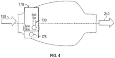
- FIG. 4 shows top view of the converter 210 shown in FIG. 3 .
- the altitude activated controller 170 includes a locking mechanism 130 that can include portions such as elements 132 and 134 ( FIG. 2 ) described above. Also illustrated is the ambient outlet 176.
Landscapes
- Engineering & Computer Science (AREA)
- Chemical & Material Sciences (AREA)
- Environmental & Geological Engineering (AREA)
- Health & Medical Sciences (AREA)
- General Chemical & Material Sciences (AREA)
- Analytical Chemistry (AREA)
- Biomedical Technology (AREA)
- Oil, Petroleum & Natural Gas (AREA)
- Chemical Kinetics & Catalysis (AREA)
- General Health & Medical Sciences (AREA)
- Pulmonology (AREA)
- Aviation & Aerospace Engineering (AREA)
- Oxygen, Ozone, And Oxides In General (AREA)
Abstract
Description
- The subject matter disclosed herein relates to an ozone converter and in particular to an ozone converter for use with an aircraft environmental control system.
- Aircraft have power systems that are comprised of several components, such as an engine, an environmental control system and a thermal management system. These systems are designed relatively independently from each other with power being transferred from one system to another.
- The environmental control system supplies pressurized air to the cabin and flight deck of an aircraft. The ambient air is drawn either from the compressor stage of an engine (a bleed air system) or a dedicated compressor. At high altitude (e.g., greater than 20,000ft (6096m)), the ambient air contains unacceptable levels of ozone (O3), Passenger comfort and/or compliance with regulations or agreements can limit the amount of ozone provided to the cabin and flight deck. As such, commercial aircraft generally include an ozone converter that converts ozone to oxygen (O2),
- Ozone converters typically include an ozone-converting core (core) that includes a catalyst which causes the ozone to decompose to oxygen. To minimize the core's exposure to contamination and extend the life of the converter, one approach is to externally bypass air around the converter when the aircraft is at low altitude.
- According to one embodiment, an ozone converter is disclosed. The converter includes an outer housing having an inlet and an outlet, a first channel disposed between the inlet and the outlet, and a bypass channel disposed between the inlet and the outlet and separated from first channel. The converter also includes a core disposed within the first channel and a bypass control mechanism that includes one more blocking elements that causes inlet air to pass through the first channel or the bypass channel based on an altitude of the ozone converter. The control mechanism includes a piston that moves between at least a first position and a second position and a bellows that controls a flow a pressurized air to the piston.
- According to another embodiment, a system that includes one or more air parameter adjusting devices that change one or both of the temperature and pressure of the input air to produce conditioned air and an ozone converter in fluid communication with the one or more air parameter adjusting devices is disclosed. The converter includes an outer housing having an inlet and an outlet, a first channel disposed between the inlet and the outlet, and a bypass channel disposed between the inlet and the outlet and separated from first channel. The converter also includes a core disposed within the first channel and a bypass control mechanism that includes one more blocking elements that causes inlet air to pass through the first channel or the bypass channel based on an altitude of the ozone converter. The control mechanism includes a piston that moves between at least a first position and a second position and a bellows that controls a flow a pressurized air to the piston.
- The subject matter which is regarded as the invention is particularly pointed out and distinctly claimed in the claims included at the conclusion of the specification. The foregoing and other features, and advantages of the invention are apparent from the following detailed description taken in conjunction with the accompanying drawings in which:
-
FIG. 1 is a block diagram illustrating a system in which embodiments of the present invention can be implemented; -
FIG. 2 shows a block diagram of one example of an altitude controlled bypass system: -
FIG. 3 shows a block diagram of another example of an altitude controlled bypass system: and -
FIG. 4 shows a perspective view of the system ofFIG. 3 . -
FIG. 1 illustrates asystem 100 in which embodiments of the present invention may be implemented. Thesystem 100 can be part of an aircraft or any other type of apparatus that can cause thesystem 100 to be moved in a forward direction. For clarity, the following description will assume that thesystem 100 is part of an aircraft but it is not so limited. - The
system 100 illustrated inFIG. 1 includes an environmental control system (ECS) 102. The ECS 102 receivesinput air 104 and providesoutput air 120 to alocation 112 within an apparatus. For example, thelocation 112 could be the flight deck or passenger compartment of an aircraft. It shall be understood that theECS 102 shown inFIG. 1 is extremely simplified and could include many other or different elements. - As illustrated, the ECS 102 includes an air
parameter adjusting unit 106. The airparameter adjusting unit 106, generally, converts the pressure and/or temperature of theinput air 104 to a desired level. In one embodiment, theinput air 104 is bleed air from a compressor section of an engine. In another embodiment, theinput air 104 is ram air received directly from the atmosphere. Regardless of the source of theinput air 104, the airparameter adjusting unit 106 may include aparameter adjustment device 108 that can be operated to adjust the temperature/pressure of theinput air 104. Theparameter adjustment device 108 includes a turbine and/or a compressor. In one embodiment, theparameter adjustment device 108 is an electric compressor that compresses ram air. - If the
input air 104 is received while the aircraft is at high altitude, there may a requirement (e.g., contractual or regulatory) that ozone be removed from theinput air 104 before being provided tolocation 112 asoutput air 120. To that end, the ECS 102 also includes anozone converter 110 coupled between the airparameter adjusting unit 106 and thelocation 112. The exact location of theozone converter 110 can be varied from that shown inFIG. 1 in different embodiments of the present invention. - As discussed above, in some cases it may be desirable to bypass the
ozone converter 110 when the ECS 102 receivesinput air 104 from a low altitude source. To accomplish this, one prior art approach was to includebypass line 116 and diverter 114 that caused theinput air 104 to be bypassed around theozone converter 110. InFIG. 1 ,bypass line 116 anddiverter 114 are shown in dashed line to indicate that they are not required (or even desired) components of theECS 102 according to one embodiment. - Embodiments of the present invention are directed to an
ozone converter 110 that can be used in thesystem 100. According to one embodiment, theozone converter 110 includes an internal bypass that allows air to bypass the ozone converter's core without requiring a separate external bypass (e.g., without requiring either diverter 114 or bypass line 116). Embodiments herein include an altitude controlled bypass system that allows the core to be bypassed at low altitude while causing air to pass through the core when the aircraft is at high altitude. That is, at high altitude, the core is not bypassed. Herein, the pressure of the air output by theparameter adjustment device 108 is above a threshold altitude that causes the bypass system to force air through the core when the aircraft is at or above 10,000 feet. This may occur when the output pressure of theparameter adjustment device 108 is above 10 psig. - In one embodiment, an evacuated bellows is used to sense altitude. Expansion and contraction of the bellows will position a variable orifice which is used to modulate the servo pressure to for bypass device's pneumatic piston. The source for servo pressure is either the ozone converter inlet or outlet in one embodiment. At low altitudes, the bellows with variable orifice controls servo pressure to ambient and the delta pressure across the piston is zero. The piston spring drives the piston to open the bypass and close the ozone converter flow path. From time to time herein, the ozone converter path may be referred to as the first or other path.
- At high altitudes, the bellows with variable orifice controls servo pressure to greater than ambient (>10 psig) and the delta pressure across the piston is sufficient to fully compress the piston spring and drive the piston to close the bypass and open the ozone converter flow path. In one embodiment, a manual wrenching feature and a lock pin are provided that can be used to lock the bypass open or closed. In the below description, the bellows driven control orifice is shown as a poppet configuration. The orifice can also be a shear configuration (i.e. fork and post). Among possible advantages, the ozone converter and bypass is completely self-contained with no external connections or control and/or no change to a main control unit (mechanical or software) is needed.
-
FIG. 2 shows an example ofozone converter 110 that includes an internal bypass system. Theozone converter 110 includes anouter housing 111 that defines at least twodifferent flow paths separator 157. Flowpath 154 passes through abypass channel 155 and flowpath 156 passes through a first orother channel 159.Inlet flow 150 is received from an external source and is provided into theozone converter 110. Theinlet flow 150 may be air received from a portion of an ECS such as a cabin air compressor (CAC). The input air may be at a pressure of anywhere from 2.5 psig at ground and about 10 psig when at or above 20,000 feet. As illustrated,ozone converter 110 includes a bypass control system that includes twoflow blocking elements control shaft 162. Rotation of theshaft 162 will cause the relative positions of the blockingelements flow paths bypass 155 orother channel 159. The exact formation of theseparator 157 that separates the bybypass channel 155 from the first orother channel 159 may be varied from that shown and may actually surround one of the channels (e.g.,FIG. 3 ). - As illustrated, the
flow path 156 is open andpath 154 is closed. In this configuration,input flow 150 is directed throughpath 156 where it is forced to pass throughozone converting core 160 disposed in thefirst channel 159. The core 160 (or any other core described herein) can be formed of any type of material that causes or otherwise aids in the conversion of ozone into oxygen. For instance, in one embodiment, thecore 160 is formed at least partially of palladium. The air inflow path 156 then leaves the converter asoutlet flow 152 with a lower ozone content that it entered (e.g., lower than contained in flow 150). - As discussed above, in some cases, it may be desirable (e.g., when on the ground) to have the air bypass the
core 160. To that end, an altitude activatedcontroller 170 includes apiston housing 192 and apiston input system 174. Thepiston input system 174 controls the pressure of the air provided to thepiston housing 192. When that air exceeds a certain value, thepiston 195 moves to an open position within thehousing 192. The "pressure" that is provided to the piston housing is provided to theinput side 192 of the piston. The other side of thepiston 195 may be referred as a compression side and be denoted byreference numeral 194.Biasing mechanisms 193 are provided that can be compressed when the pressure in theinput side 192 exceeds the force provided by the biasing mechanisms. An example of biasingmechanism 192 is a spring but any mechanism may be employed. - As illustrated in
FIG. 2 , thepiston 195 has been shifted away from theouter housing 192 in the direction generally shown by arrow A. As discussed above, this occurs when the pressure in theinput side 192 exceeds the force exerted in direction B by biasingmechanism 193. Thepiston 195 is physically connected either directly or through a linkage to theshaft 162. When thepiston 195 moves in direction A, theshaft 162 is rotated or otherwise altered such that blockingelement 164 closes offpath 154 and blockingelement 166 is arranged such thatinput flow 150 is allowed to pass throughflow path 156 and, consequently, throughcore 160. Such a case may occur, for example, when the pressure of the input flow is at or above about 10 psig. In contrast, when the pressure on theinput side 192 is less than the force provided in direction B by thebiasing mechanism 193, the piston will move in direction B. When thepiston 195 moves in direction B, theshaft 162 is rotated or otherwise altered such that blockingelement 166 closes offpath 156 and blockingelement 166 is arranged such thatinput flow 150 is allowed to pass throughflow path 154 and, consequently, through bypassingcore 160. Such may occur when the aircraft is on the ground our below a certain altitude such as 10,000 or 15,000 feet. - It shall be understood that the pressure on the input side is received from the
input flow 150. As illustrated, this can be achieved by providing a path through an inletflow diverter passage 172. Thediverter passage 172 provides a portion of theinput flow 150 to a variable orifice flow control element shown aselement 174. Theflow control element 174 includes adivider 178 that includes anorifice 180 or hole formed therein. The portion of the orifice through which air may pass is controlled by the position of astopper element 184. The combination of thestopper element 184 and theorifice 180 may form a so-called "poppet valve." Asstopper element 184 is moved to increase the portion of theorifice 180 through which air may pass, the pressure on theinput side 192 will approximate the pressure offlow 150. The pressure offlow 150 may be controlled by the air parameter adjusting unit 106 (FIG. 1 ) that may be a part of the ECS such as a CAC. As illustrated, the air provided to the input side is received from the input flow. In another embodiment, the air could be received from theoutput flow 152. In such a case, the location where the inletflow diverter passage 172 is connected can be moved such that it receives the output flow. - The
flow control element 174 includes apiston connection 199 that fluidly connects it to inputside 192. Theflow control element 174 may also include anambient outlet 176 configured to allow air to vent to ambient viaambient outlet 176. The sizing of theambient outlet 176 can be such that most of the air pressure is directed towards theinput side 192 when the aircraft is over a certain height and the pressure of theinput air 150 is greater than the ambient air pressure. In one embodiment, after the aircraft lands or falls below a certain altitude, and the poppet valve (e.g., the stopper element andorifice 180 combination) has closed, the pressure in theinput side 192 is allowed to vent throughoutlet 176 to ambient overtime. As this happens, thebiasing mechanism 193 will return to a "base" position by moving in direction B and causing the bypass path (path 154) to be opened in the manner as described above. - As described above, the location of
piston 195 controls whether theinput flow 150 that is not passing intodiverter passage 172 passes throughpath 154 orpath 156. Further, as described above, the location of the piston is determined by whether or not the poppet valve is open. The poppet valve is open whenstopper 184 is in an extended position and is closed when it is in the retracted position. The location of thestopper 184 is determined by the state of a bellows 183. The bellows 183 is connected is connected to and controls the positon of acontrol rod 182 or other connector fixed to the stopper. The bellows 183 expands when ambient air pressure reduces. Such expansion will cause the stopper 184 (via rod 182) to open theorifice 180 and cause thepiston 195 to move in direction A. As described above, this will cause theflow 150 to followpath 156 and pass throughcore 160 to remove ozone from it. In one embodiment, thebellows 183 may be sized or otherwise configured such that it causes theorifice 180 to open at or above 10,000 feet. - An optional manual locking element comprised of a
pin 132 and alock 134 may also be provide to lock theconverter 110 into a bypass mode in the event that the core is fouled. It shall be understood that the above elements could lock the converter into another mode as well and other combinations of elements may be utilized to provide a locking element to lock the converter into a particular mode. -
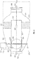
FIG. 3 illustrates an embodiment of another type of internalbypass ozone converter 210 in the "open" or "bypass" state. Theozone converter 210 includes two separate air passages though which air can pass through it. In particular, theozone converter 210 includes anouter passage 202 and aninternal bypass 204. In this embodiment, theouter passage 202 surrounds at least a portion of theinternal bypass 204. Theozone converter 210 includes an altitude activatedcontroller 170 connected thereto. The altitude activatedcontroller 170 may work in the same manner as described above. Whileconnection 172 is shown as being connectedouter passage 202 it shall be understood that it can located at any location where it receives an inlet flow such asflow 150. - The
ozone converter 210 includes aninlet 206 and anoutlet 208. Regardless of the state of theozone converter 210, air enters atinlet 206 and exits atoutlet 208. In the illustrated embodiment, theinlet 206 andoutlet 208 are connected to one another by anexterior shell 210, which is also referred to as outer shell orouter housing 210. The term "downstream" as used herein related to components or locations shall refer to the order in which a substance (e.g. air) traverses the components. In particular, a component or location is downstream of another if air passes through the component or location after passing through the other component or location. For example, assuming air is flowing from left to right inFIG. 3 ,outlet 208 is downstream ofinlet 206. Conversely, and in the same vein,inlet 206 is upstream ofoutlet 208. - Enclosed within the outer shell is a
core 212. Thecore 212 can be formed of any type of material that causes or otherwise aids in the conversion of ozone into oxygen. For instance, in one embodiment, thecore 212 is formed at least partially of palladium. In one embodiment, theinternal bypass 204 passes through thecore 212. That is, air that enters theinternal bypass 204 can traverse from theinlet 206 to theoutlet 208 without contacting thecore 212. In one embodiment, theinternal bypass 204 is arranged along acentral axis 214 of theozone converter 210 and has a generally cylindrical shape. Abypass cylinder 205 defines theinternal bypass 204 in one embodiment. - The
bypass cylinder 205 includes a blockingelement 220 disposed therein. In one embodiment, the blockingelement 220 is circular disc. The blockingelement 220 can be translated from an open position where air can travel through theinternal bypass 204 to a closed position where it blocks air from passing throughinternal bypass 204. As such, the blockingelement 220 has area that is the same or nearly the same as an area of an inner diameter of thebypass cylinder 205 so that it can effectively block air from traveling through thebypass cylinder 205 when theozone converter 210 is in the bypass state. In one embodiment, the translation from the open to closed position (and vice-versa) can be effected by rotation of arod 221 to which theblocking element 220 is coupled. In combination, therod 221 and the blockingelement 220 form a butterfly valve. As illustrated, therod 221 passes through the walls of thebypasses cylinder 205 at two locations. The altitude activatedcontroller 170 controls the positioning of therod 221 and, thus, controls, whether theconverter 210 is in the open or closed position. - In the illustrated embodiment, air is prevented from entering the
outer passage 202 by a blockingsleeve 222 that surrounds a portion of thebypass cylinder 205 proximal theinlet 206. The blockingsleeve 222 is arranged such that when the blockingelement 220 is in the open position (e.g., theozone converter 210 is in the bypass state), the blockingsleeve 222 blocks air from entering an outer passage opening 224 that exists between theinlet 206 and anend 230 of thebypass cylinder 205. As generally described above, in one embodiment, theother end 232 of thebypass cylinder 205 extends to a location downstream of thecore 212. It shall be understood, however, that the blockingsleeve 222 could be disposed within thebypass cylinder 205 in one embodiment. InFIG. 3 , the path offlow 150 through theozone converter 210 is shown byarrows 240. -
FIG. 4 shows top view of theconverter 210 shown inFIG. 3 . The altitude activatedcontroller 170 includes alocking mechanism 130 that can include portions such aselements 132 and 134 (FIG. 2 ) described above. Also illustrated is theambient outlet 176. - While the invention has been described in detail in connection with only a limited number of embodiments, it should be readily understood that the invention is not limited to such disclosed embodiments. Rather, the invention can be modified to incorporate any number of variations, alterations, substitutions or equivalent arrangements not heretofore described, but which are commensurate with the spirit and scope of the invention. Additionally, while various embodiments of the invention have been described, it is to be understood that aspects of the invention may include only some of the described embodiments. Accordingly, the invention is not to be seen as limited by the foregoing description, but is only limited by the scope of the appended claims.
Claims (15)
- An ozone converter (110, 210) comprising:an outer housing (111) having an inlet (206) and an outlet (208);a first channel (159) disposed between the inlet and the outlet;a bypass channel disposed between the inlet and the outlet and separated from first channel;a core (160, 212) disposed within the first channel; anda bypass control mechanism that includes one more blocking elements that causes inlet air to pass through the first channel or the bypass channel based on an altitude of the ozone converter, the control mechanism including:a piston (195) that moves between at least a first position and a second position; anda bellows (183) that controls a flow a pressurized air to the piston.
- The ozone converter of claim 1, wherein when the bellows (183) is in a compressed state, the pressurized air is blocked from contacting the piston.
- The ozone converter of claim 1 or 2, wherein the bellows (183) is connected to and controls the operation of a poppet valve that blocks the pressurized air from reaching the piston when the ozone converter is below a threshold altitude.
- The ozone converter of any preceding claim, wherein the bypass control mechanism further includes a flow control element including:an inlet;a piston connection;an ambient outlet; anda separator wall disposed between the inlet and one or both of the piston connection and the ambient outlet;wherein the bellows is connected to a blocking element that is arranged to control a flow of air received at the inlet through the orifice based on movement of the bellows.
- The ozone converter of claim 4, wherein the piston is contained in a piston housing and separates the housing into an input side and a compression side, and
wherein, the piston connection fluidly connects the flow control element to the input side. - The ozone converter of claim 5, wherein the piston is connected to a biasing mechanism that urges the piston to compress the inlet side.
- The ozone converter of claim 6, further comprising:a blocking sleeve that surrounds a portion of the bypass channel and that is moveable from a first position to a second position, wherein in the first position air that enters in the inlet is directed by the blocking sleeve into the bypass channel and in the second position air that enters the inlet is allowed to enter the first channel;wherein the first channel surrounds the bypass channel.
- The ozone converter of claim 6, wherein the piston is connected to a rod that, when moved, causes the one or more blocking elements to move.
- A system comprising:one or more air parameter adjusting devices that change one or both of the temperature and pressure of the input air to produce conditioned air; andthe ozone converter of any preceding claim in fluid communication with the one or more air parameter adjusting devices.
- The system of claim 9, wherein the pressurized air is received from the one or more air parameter adjusting devices.
- The system of claim 9 or 10, wherein when the bellows is in a compressed state, the pressurized air is blocked from contacting the piston.
- The system of claim 9, 10 or 11, wherein the bellows is connected to and controls the operation of a poppet valve that blocks the pressurized air from reaching the piston when the ozone converter is below a threshold altitude.
- The system of claim 9, 10, 11 or 12, wherein the bypass control mechanism further includes a flow control element including:an inlet fluidly connected to the inlet;a piston connection;an ambient outlet; anda separator wall disposed between the inlet and one or both of the piston connection and the ambient outlet;wherein the bellows is connected to a blocking element that is arranged to control a flow of air received at the inlet through the orifice based on movement of the bellows.
- The system of claim 13, wherein the piston is contained in a piston housing and separates the housing into an input side and a compression side, and
wherein, the piston connection fluidly connects the flow control element to the input side. - The system of claim 14, wherein the piston is connected to a biasing mechanism that urges the piston to compress the inlet side.
Applications Claiming Priority (1)
| Application Number | Priority Date | Filing Date | Title |
|---|---|---|---|
| US15/205,063 US10239625B2 (en) | 2016-07-08 | 2016-07-08 | Ozone converter with altitude activated actuator |
Publications (2)
| Publication Number | Publication Date |
|---|---|
| EP3266513A1 true EP3266513A1 (en) | 2018-01-10 |
| EP3266513B1 EP3266513B1 (en) | 2020-04-01 |
Family
ID=59294959
Family Applications (1)
| Application Number | Title | Priority Date | Filing Date |
|---|---|---|---|
| EP17179563.6A Active EP3266513B1 (en) | 2016-07-08 | 2017-07-04 | Ozone converter with altitude activated actuator |
Country Status (2)
| Country | Link |
|---|---|
| US (1) | US10239625B2 (en) |
| EP (1) | EP3266513B1 (en) |
Citations (8)
| Publication number | Priority date | Publication date | Assignee | Title |
|---|---|---|---|---|
| US2620719A (en) * | 1938-06-27 | 1952-12-09 | Boeing Co | Rate-of-pressure change controls for pressure cabins |
| US2867989A (en) * | 1955-02-17 | 1959-01-13 | United Aircraft Corp | Water separator de-icing control |
| US3035408A (en) * | 1960-01-04 | 1962-05-22 | Garrett Corp | Waste gate control for supercharger turbines |
| GB2106635A (en) * | 1981-07-20 | 1983-04-13 | United Technologies Corp | Temperature and pressure control for environmental control system for aircraft |
| US5429663A (en) * | 1992-06-01 | 1995-07-04 | Pall Corporation | Removal in aircraft of components from fluid mixtures |
| JPH0999047A (en) * | 1995-10-09 | 1997-04-15 | Zexel Corp | Ozonic fumigatory sterilizer |
| EP2583743A1 (en) * | 2011-10-17 | 2013-04-24 | Hamilton Sundstrand Corporation | Ozone converter with internal bypass |
| WO2015055672A1 (en) * | 2013-10-14 | 2015-04-23 | Liebherr-Aerospace Toulouse Sas | System for treating air, in particular at a low temperature, for an aircraft |
Family Cites Families (3)
| Publication number | Priority date | Publication date | Assignee | Title |
|---|---|---|---|---|
| US4391290A (en) | 1980-10-23 | 1983-07-05 | General Electric Company | Altitude sensing control apparatus for a gas turbine engine |
| US9133028B2 (en) | 2013-04-15 | 2015-09-15 | Hamilton Sundstrand Corporation | Ozone converter with replaceable core |
| US10059430B2 (en) | 2014-06-25 | 2018-08-28 | Gulfstream Aerospace Corporation | Aircraft air scoop systems with passive pneumatic actuators |
-
2016
- 2016-07-08 US US15/205,063 patent/US10239625B2/en active Active
-
2017
- 2017-07-04 EP EP17179563.6A patent/EP3266513B1/en active Active
Patent Citations (8)
| Publication number | Priority date | Publication date | Assignee | Title |
|---|---|---|---|---|
| US2620719A (en) * | 1938-06-27 | 1952-12-09 | Boeing Co | Rate-of-pressure change controls for pressure cabins |
| US2867989A (en) * | 1955-02-17 | 1959-01-13 | United Aircraft Corp | Water separator de-icing control |
| US3035408A (en) * | 1960-01-04 | 1962-05-22 | Garrett Corp | Waste gate control for supercharger turbines |
| GB2106635A (en) * | 1981-07-20 | 1983-04-13 | United Technologies Corp | Temperature and pressure control for environmental control system for aircraft |
| US5429663A (en) * | 1992-06-01 | 1995-07-04 | Pall Corporation | Removal in aircraft of components from fluid mixtures |
| JPH0999047A (en) * | 1995-10-09 | 1997-04-15 | Zexel Corp | Ozonic fumigatory sterilizer |
| EP2583743A1 (en) * | 2011-10-17 | 2013-04-24 | Hamilton Sundstrand Corporation | Ozone converter with internal bypass |
| WO2015055672A1 (en) * | 2013-10-14 | 2015-04-23 | Liebherr-Aerospace Toulouse Sas | System for treating air, in particular at a low temperature, for an aircraft |
Also Published As
| Publication number | Publication date |
|---|---|
| EP3266513B1 (en) | 2020-04-01 |
| US10239625B2 (en) | 2019-03-26 |
| US20180009537A1 (en) | 2018-01-11 |
Similar Documents
| Publication | Publication Date | Title |
|---|---|---|
| EP1695910B1 (en) | On-board inert gas generation system and method | |
| EP1536958B1 (en) | Pneumatic suspension system for a vehicle | |
| EP2583743B1 (en) | Ozone converter with internal bypass | |
| EP2792400B1 (en) | Ozone converter with replaceable core | |
| US4506594A (en) | Fluid flow control apparatus and method | |
| DE69714300T2 (en) | INTEGRATED VALVES AND AIR CIRCUIT MACHINE | |
| US20170218853A1 (en) | Methods and apparatus to adjust bleed ports on an aircraft engine | |
| US20170335775A1 (en) | Solenoids for gas turbine engine bleed valves | |
| US7066808B2 (en) | Aircraft cabin multi-differential pressure control system | |
| US20140137540A1 (en) | Engine and thrust reverser actuation system | |
| EP3266513B1 (en) | Ozone converter with altitude activated actuator | |
| DE10240359A1 (en) | Pneumatic shock absorption facility partly closed for a motor vehicle sucks air in from the atmosphere while also evacuating air into the atmosphere | |
| US20050135930A1 (en) | Device for providing assistance to the pilot of a rotorcraft in the event of engine failure | |
| GB2119862A (en) | Variable stator vane (VSV) closed loop control system of a compressor | |
| EP3315189B1 (en) | Ozone converter bypass | |
| EP3628898B1 (en) | Three-position poppet valve | |
| CN108661972B (en) | Control valve assembly and cylinder of integrated control valve | |
| EP4350128A1 (en) | Pressure regulating shut-off valve | |
| DE102005013658B4 (en) | Pulse regulator | |
| EP3986765B1 (en) | System for cooling technical units in a rail vehicle | |
| DE69024828T2 (en) | Auxiliary oxygen bottle for aircraft personnel | |
| US10710728B2 (en) | Device for determining at least one of a degree of opening of an air opening and a cross section of an air duct connected to the opening | |
| KR101775244B1 (en) | Combination manifold valve | |
| WO2026082359A1 (en) | Pneumatic wheel valve | |
| DE1530251B (en) | Pressure regulator for vacuum rail vehicle brakes |
Legal Events
| Date | Code | Title | Description |
|---|---|---|---|
| PUAI | Public reference made under article 153(3) epc to a published international application that has entered the european phase |
Free format text: ORIGINAL CODE: 0009012 |
|
| STAA | Information on the status of an ep patent application or granted ep patent |
Free format text: STATUS: THE APPLICATION HAS BEEN PUBLISHED |
|
| AK | Designated contracting states |
Kind code of ref document: A1 Designated state(s): AL AT BE BG CH CY CZ DE DK EE ES FI FR GB GR HR HU IE IS IT LI LT LU LV MC MK MT NL NO PL PT RO RS SE SI SK SM TR |
|
| AX | Request for extension of the european patent |
Extension state: BA ME |
|
| STAA | Information on the status of an ep patent application or granted ep patent |
Free format text: STATUS: REQUEST FOR EXAMINATION WAS MADE |
|
| 17P | Request for examination filed |
Effective date: 20180710 |
|
| RBV | Designated contracting states (corrected) |
Designated state(s): AL AT BE BG CH CY CZ DE DK EE ES FI FR GB GR HR HU IE IS IT LI LT LU LV MC MK MT NL NO PL PT RO RS SE SI SK SM TR |
|
| STAA | Information on the status of an ep patent application or granted ep patent |
Free format text: STATUS: EXAMINATION IS IN PROGRESS |
|
| 17Q | First examination report despatched |
Effective date: 20181212 |
|
| GRAP | Despatch of communication of intention to grant a patent |
Free format text: ORIGINAL CODE: EPIDOSNIGR1 |
|
| STAA | Information on the status of an ep patent application or granted ep patent |
Free format text: STATUS: GRANT OF PATENT IS INTENDED |
|
| RIC1 | Information provided on ipc code assigned before grant |
Ipc: B64D 13/06 20060101ALN20190918BHEP Ipc: B01D 53/86 20060101AFI20190918BHEP |
|
| INTG | Intention to grant announced |
Effective date: 20191022 |
|
| RAP1 | Party data changed (applicant data changed or rights of an application transferred) |
Owner name: HAMILTON SUNDSTRAND CORPORATION |
|
| GRAS | Grant fee paid |
Free format text: ORIGINAL CODE: EPIDOSNIGR3 |
|
| GRAA | (expected) grant |
Free format text: ORIGINAL CODE: 0009210 |
|
| STAA | Information on the status of an ep patent application or granted ep patent |
Free format text: STATUS: THE PATENT HAS BEEN GRANTED |
|
| AK | Designated contracting states |
Kind code of ref document: B1 Designated state(s): AL AT BE BG CH CY CZ DE DK EE ES FI FR GB GR HR HU IE IS IT LI LT LU LV MC MK MT NL NO PL PT RO RS SE SI SK SM TR |
|
| REG | Reference to a national code |
Ref country code: GB Ref legal event code: FG4D |
|
| REG | Reference to a national code |
Ref country code: CH Ref legal event code: EP Ref country code: AT Ref legal event code: REF Ref document number: 1250636 Country of ref document: AT Kind code of ref document: T Effective date: 20200415 |
|
| REG | Reference to a national code |
Ref country code: DE Ref legal event code: R096 Ref document number: 602017013854 Country of ref document: DE |
|
| REG | Reference to a national code |
Ref country code: IE Ref legal event code: FG4D |
|
| PG25 | Lapsed in a contracting state [announced via postgrant information from national office to epo] |
Ref country code: BG Free format text: LAPSE BECAUSE OF FAILURE TO SUBMIT A TRANSLATION OF THE DESCRIPTION OR TO PAY THE FEE WITHIN THE PRESCRIBED TIME-LIMIT Effective date: 20200701 |
|
| REG | Reference to a national code |
Ref country code: NL Ref legal event code: MP Effective date: 20200401 |
|
| REG | Reference to a national code |
Ref country code: LT Ref legal event code: MG4D |
|
| PG25 | Lapsed in a contracting state [announced via postgrant information from national office to epo] |
Ref country code: IS Free format text: LAPSE BECAUSE OF FAILURE TO SUBMIT A TRANSLATION OF THE DESCRIPTION OR TO PAY THE FEE WITHIN THE PRESCRIBED TIME-LIMIT Effective date: 20200801 Ref country code: CZ Free format text: LAPSE BECAUSE OF FAILURE TO SUBMIT A TRANSLATION OF THE DESCRIPTION OR TO PAY THE FEE WITHIN THE PRESCRIBED TIME-LIMIT Effective date: 20200401 Ref country code: FI Free format text: LAPSE BECAUSE OF FAILURE TO SUBMIT A TRANSLATION OF THE DESCRIPTION OR TO PAY THE FEE WITHIN THE PRESCRIBED TIME-LIMIT Effective date: 20200401 Ref country code: GR Free format text: LAPSE BECAUSE OF FAILURE TO SUBMIT A TRANSLATION OF THE DESCRIPTION OR TO PAY THE FEE WITHIN THE PRESCRIBED TIME-LIMIT Effective date: 20200702 Ref country code: NO Free format text: LAPSE BECAUSE OF FAILURE TO SUBMIT A TRANSLATION OF THE DESCRIPTION OR TO PAY THE FEE WITHIN THE PRESCRIBED TIME-LIMIT Effective date: 20200701 Ref country code: SE Free format text: LAPSE BECAUSE OF FAILURE TO SUBMIT A TRANSLATION OF THE DESCRIPTION OR TO PAY THE FEE WITHIN THE PRESCRIBED TIME-LIMIT Effective date: 20200401 Ref country code: NL Free format text: LAPSE BECAUSE OF FAILURE TO SUBMIT A TRANSLATION OF THE DESCRIPTION OR TO PAY THE FEE WITHIN THE PRESCRIBED TIME-LIMIT Effective date: 20200401 Ref country code: LT Free format text: LAPSE BECAUSE OF FAILURE TO SUBMIT A TRANSLATION OF THE DESCRIPTION OR TO PAY THE FEE WITHIN THE PRESCRIBED TIME-LIMIT Effective date: 20200401 Ref country code: PT Free format text: LAPSE BECAUSE OF FAILURE TO SUBMIT A TRANSLATION OF THE DESCRIPTION OR TO PAY THE FEE WITHIN THE PRESCRIBED TIME-LIMIT Effective date: 20200817 |
|
| REG | Reference to a national code |
Ref country code: AT Ref legal event code: MK05 Ref document number: 1250636 Country of ref document: AT Kind code of ref document: T Effective date: 20200401 |
|
| PG25 | Lapsed in a contracting state [announced via postgrant information from national office to epo] |
Ref country code: HR Free format text: LAPSE BECAUSE OF FAILURE TO SUBMIT A TRANSLATION OF THE DESCRIPTION OR TO PAY THE FEE WITHIN THE PRESCRIBED TIME-LIMIT Effective date: 20200401 Ref country code: RS Free format text: LAPSE BECAUSE OF FAILURE TO SUBMIT A TRANSLATION OF THE DESCRIPTION OR TO PAY THE FEE WITHIN THE PRESCRIBED TIME-LIMIT Effective date: 20200401 Ref country code: LV Free format text: LAPSE BECAUSE OF FAILURE TO SUBMIT A TRANSLATION OF THE DESCRIPTION OR TO PAY THE FEE WITHIN THE PRESCRIBED TIME-LIMIT Effective date: 20200401 |
|
| PG25 | Lapsed in a contracting state [announced via postgrant information from national office to epo] |
Ref country code: AL Free format text: LAPSE BECAUSE OF FAILURE TO SUBMIT A TRANSLATION OF THE DESCRIPTION OR TO PAY THE FEE WITHIN THE PRESCRIBED TIME-LIMIT Effective date: 20200401 |
|
| REG | Reference to a national code |
Ref country code: DE Ref legal event code: R097 Ref document number: 602017013854 Country of ref document: DE |
|
| PG25 | Lapsed in a contracting state [announced via postgrant information from national office to epo] |
Ref country code: AT Free format text: LAPSE BECAUSE OF FAILURE TO SUBMIT A TRANSLATION OF THE DESCRIPTION OR TO PAY THE FEE WITHIN THE PRESCRIBED TIME-LIMIT Effective date: 20200401 Ref country code: DK Free format text: LAPSE BECAUSE OF FAILURE TO SUBMIT A TRANSLATION OF THE DESCRIPTION OR TO PAY THE FEE WITHIN THE PRESCRIBED TIME-LIMIT Effective date: 20200401 Ref country code: EE Free format text: LAPSE BECAUSE OF FAILURE TO SUBMIT A TRANSLATION OF THE DESCRIPTION OR TO PAY THE FEE WITHIN THE PRESCRIBED TIME-LIMIT Effective date: 20200401 Ref country code: SM Free format text: LAPSE BECAUSE OF FAILURE TO SUBMIT A TRANSLATION OF THE DESCRIPTION OR TO PAY THE FEE WITHIN THE PRESCRIBED TIME-LIMIT Effective date: 20200401 Ref country code: RO Free format text: LAPSE BECAUSE OF FAILURE TO SUBMIT A TRANSLATION OF THE DESCRIPTION OR TO PAY THE FEE WITHIN THE PRESCRIBED TIME-LIMIT Effective date: 20200401 Ref country code: IT Free format text: LAPSE BECAUSE OF FAILURE TO SUBMIT A TRANSLATION OF THE DESCRIPTION OR TO PAY THE FEE WITHIN THE PRESCRIBED TIME-LIMIT Effective date: 20200401 Ref country code: ES Free format text: LAPSE BECAUSE OF FAILURE TO SUBMIT A TRANSLATION OF THE DESCRIPTION OR TO PAY THE FEE WITHIN THE PRESCRIBED TIME-LIMIT Effective date: 20200401 |
|
| REG | Reference to a national code |
Ref country code: DE Ref legal event code: R119 Ref document number: 602017013854 Country of ref document: DE |
|
| PLBE | No opposition filed within time limit |
Free format text: ORIGINAL CODE: 0009261 |
|
| STAA | Information on the status of an ep patent application or granted ep patent |
Free format text: STATUS: NO OPPOSITION FILED WITHIN TIME LIMIT |
|
| PG25 | Lapsed in a contracting state [announced via postgrant information from national office to epo] |
Ref country code: MC Free format text: LAPSE BECAUSE OF FAILURE TO SUBMIT A TRANSLATION OF THE DESCRIPTION OR TO PAY THE FEE WITHIN THE PRESCRIBED TIME-LIMIT Effective date: 20200401 Ref country code: PL Free format text: LAPSE BECAUSE OF FAILURE TO SUBMIT A TRANSLATION OF THE DESCRIPTION OR TO PAY THE FEE WITHIN THE PRESCRIBED TIME-LIMIT Effective date: 20200401 Ref country code: SK Free format text: LAPSE BECAUSE OF FAILURE TO SUBMIT A TRANSLATION OF THE DESCRIPTION OR TO PAY THE FEE WITHIN THE PRESCRIBED TIME-LIMIT Effective date: 20200401 |
|
| REG | Reference to a national code |
Ref country code: CH Ref legal event code: PL |
|
| 26N | No opposition filed |
Effective date: 20210112 |
|
| REG | Reference to a national code |
Ref country code: BE Ref legal event code: MM Effective date: 20200731 |
|
| PG25 | Lapsed in a contracting state [announced via postgrant information from national office to epo] |
Ref country code: LI Free format text: LAPSE BECAUSE OF NON-PAYMENT OF DUE FEES Effective date: 20200731 Ref country code: LU Free format text: LAPSE BECAUSE OF NON-PAYMENT OF DUE FEES Effective date: 20200704 Ref country code: CH Free format text: LAPSE BECAUSE OF NON-PAYMENT OF DUE FEES Effective date: 20200731 Ref country code: IE Free format text: LAPSE BECAUSE OF NON-PAYMENT OF DUE FEES Effective date: 20200704 |
|
| PG25 | Lapsed in a contracting state [announced via postgrant information from national office to epo] |
Ref country code: SI Free format text: LAPSE BECAUSE OF FAILURE TO SUBMIT A TRANSLATION OF THE DESCRIPTION OR TO PAY THE FEE WITHIN THE PRESCRIBED TIME-LIMIT Effective date: 20200401 Ref country code: DE Free format text: LAPSE BECAUSE OF NON-PAYMENT OF DUE FEES Effective date: 20210202 Ref country code: BE Free format text: LAPSE BECAUSE OF NON-PAYMENT OF DUE FEES Effective date: 20200731 |
|
| PG25 | Lapsed in a contracting state [announced via postgrant information from national office to epo] |
Ref country code: TR Free format text: LAPSE BECAUSE OF FAILURE TO SUBMIT A TRANSLATION OF THE DESCRIPTION OR TO PAY THE FEE WITHIN THE PRESCRIBED TIME-LIMIT Effective date: 20200401 Ref country code: MT Free format text: LAPSE BECAUSE OF FAILURE TO SUBMIT A TRANSLATION OF THE DESCRIPTION OR TO PAY THE FEE WITHIN THE PRESCRIBED TIME-LIMIT Effective date: 20200401 Ref country code: CY Free format text: LAPSE BECAUSE OF FAILURE TO SUBMIT A TRANSLATION OF THE DESCRIPTION OR TO PAY THE FEE WITHIN THE PRESCRIBED TIME-LIMIT Effective date: 20200401 |
|
| PG25 | Lapsed in a contracting state [announced via postgrant information from national office to epo] |
Ref country code: MK Free format text: LAPSE BECAUSE OF FAILURE TO SUBMIT A TRANSLATION OF THE DESCRIPTION OR TO PAY THE FEE WITHIN THE PRESCRIBED TIME-LIMIT Effective date: 20200401 |
|
| P01 | Opt-out of the competence of the unified patent court (upc) registered |
Effective date: 20230522 |
|
| PGFP | Annual fee paid to national office [announced via postgrant information from national office to epo] |
Ref country code: GB Payment date: 20250619 Year of fee payment: 9 |
|
| PGFP | Annual fee paid to national office [announced via postgrant information from national office to epo] |
Ref country code: FR Payment date: 20250620 Year of fee payment: 9 |